ipmi intelligent chassis management bus bridge ... chassis management bus bridge specification intel...
TRANSCRIPT

- IPMI -
Intelligent Chassis Management Bus Bridge Specification
v1.0
Document Revision 1.3
April 2, 2003
Intel Hewlett-Packard NEC Dell

Intelligent Chassis Management Bus Bridge Specification
ii Intel / HP / NEC / Dell
Copyright © 1999, 2000, 2001, 2002, 2003 Intel Corporation, Hewlett-Packard Company, NEC Corporation, Dell Computer Corporation, All rights reserved.
INTELLECTUAL PROPERTY DISCLAIMER
THIS SPECIFICATION IS PROVIDED “AS IS” WITH NO WARRANTIES WHATSOEVER INCLUDING ANY WARRANTY OF MERCHANTABILITY, FITNESS FOR ANY PARTICULAR PURPOSE, OR ANY WARRANTY OTHERWISE ARISING OUT OF ANY PROPOSAL, SPECIFICATION, OR SAMPLE.
NO LICENSE, EXPRESS OR IMPLIED, BY ESTOPPEL OR OTHERWISE, TO ANY INTELLECTUAL PROPERTY RIGHTS IS GRANTED OR INTENDED HEREBY.
INTEL, HEWLETT-PACKARD, NEC, AND DELL DISCLAIM ALL LIABILITY, INCLUDING LIABILITY FOR INFRINGEMENT OF PROPRIETARY RIGHTS, RELATING TO IMPLEMENTATION OF INFORMATION IN THIS SPECIFICATION. INTEL, HEWLETT-PACKARD, NEC, AND DELL, DO NOT WARRANT OR REPRESENT THAT SUCH IMPLEMENTATION(S) WILL NOT INFRINGE SUCH RIGHTS.
I2C is a trademark of Philips Semiconductors. All other product names are trademarks, registered trademarks, or servicemarks of their respective owners.
I2C is a two-wire communications bus/protocol developed by Philips. IPMB is a subset of the I2C bus/protocol and was developed by Intel. Implementations of the I2C bus/protocol or the IPMB bus/protocol may require licenses from various entities, including Philips Electronics N.V. and North American Philips Corporation.
Intel, Hewlett-Packard, NEC, and Dell retain the right to make changes to this document at any time, without notice. Intel, Hewlett-Packard, NEC, and Dell make no warranty for the use of this document and assumes no responsibility for any error which may appear in the document nor does it make a commitment to update the information contained herein.

Intelligent Chassis Management Bus Bridge Specification
Intel / HP / NEC / Dell iii
IPMI NON-DISCLOSURE AGREEMENT DO NOT download these files (collectively, the “Confidential Information”) until you have carefully read the following terms and conditions. By downloading the Confidential Information you agree to the terms of this Agreement. If you do not wish to so agree, do not download the Confidential Information. 1. Confidential Information. The confidential, proprietary and trade secret information being disclosed ("Confidential
Information"), is that information marked with a "confidential", "proprietary", or similar legend, and is described as: Confidential Information: Intelligent Platform Management Interface Specification (v1.5), Intelligent Platform
Management Bus Bridge Specification (v1.0), Intelligent Chassis Management Bus Bridge Specification (v1.3) CONFIDENTIAL INFORMATION IS PROVIDED SOLELY FOR YOUR INTERNAL EVALUATION AND REVIEW TO DETERMINE WHETHER TO ADOPT THE SPECIFICATIONS BY SIGNING A SEPARATE ADOPTER’S AGREEMENT. THE RECEIVING PARTY IS NOT LICENSED TO IMPLEMENT THE SPECIFICATIONS UNLESS OR UNTIL AN ADOPTER’S AGREEMENT IS EXECUTED.
Disclosing party’s representatives for disclosing Confidential Information is: Fadi Zuhayri ([email protected]) 2. Obligations of Receiving Party. The receiving party will maintain the confidentiality of the Confidential Information of
the disclosing party with at least the same degree of care that it uses to protect its own confidential and proprietary information, but no less than a reasonable degree of care under the circumstances. The receiving party will not disclose any of the disclosing party’s Confidential Information to employees or to any third parties except to the receiving party’s employees, parent company and majority-owned subsidiaries who have a need to know and who agree to abide by nondisclosure terms at least as comprehensive as those set forth herein; provided that the receiving party will be liable for breach by any such entity. The receiving party will not make any copies of Confidential Information received from the disclosing party except as necessary for its employees, parent company and majority-owned subsidiaries with a need to know. Any copies which are made will be identified as belonging to the disclosing party and marked "confidential", "proprietary" or with a similar legend.
3. Period of Non-Assertion. Unless a shorter period is indicated below, the disclosing party will not assert any claims
for breach of this Agreement or misappropriation of trade secrets against the receiving party arising out of the receiving party’s disclosure of disclosing party’s Confidential Information made more than five (5) years from the date of receipt of the Confidential Information by the receiving party. However, unless at least one of the exceptions set forth in Section 4 below has occurred, the receiving party will continue to treat such Confidential Information as the confidential information of the disclosing party and only disclose any such Confidential Information to third parties under the terms of a non-disclosure agreement.
4. Termination of Obligation of Confidentiality. The receiving party will not be liable for the disclosure of any Confidential
Information which is: (a) rightfully in the public domain other than by a breach of this Agreement of a duty to the disclosing party; (b) rightfully received from a third party without any obligation of confidentiality; (c) rightfully known to the receiving party without any limitation on use or disclosure prior to its receipt from the disclosing party; (d) independently developed by employees of the receiving party; or (e) generally made available to third parties by the disclosing party without restriction on disclosure.
5. Title. Title or the right to possess Confidential Information as between the parties will remain in the disclosing party. 6. No Obligation of Disclosure; Termination The disclosing party may terminate this Agreement at any time without
cause upon written notice to the other party; provided that the receiving party’s obligations with respect to information disclosed during the term of this Agreement will survive any such termination. The disclosing party may, at any time: (a) cease giving Confidential Information to the other party without any liability, and/or (b) request in writing the return or destruction of all or part of its Confidential Information previously disclosed, and all copies thereof, and the receiving party will promptly comply with such request, and certify in writing its compliance.
7. General.
(a) This Agreement is neither intended to nor will it be construed as creating a joint venture, partnership or other form of business association between the parties, nor an obligation to buy or sell products using or incorporating the Confidential Information.
(b) No license under any patent, copyright, trade secret or other intellectual property right is granted to or conferred upon either party in this Agreement or by the transfer of any information by one party to the other party as contemplated hereunder, either expressly, by implication, inducement, estoppel or otherwise, and that any license under any such intellectual property rights must be express and in writing.
(c) The failure of either party to enforce any right resulting from breach of any provision of this Agreement will not be deemed a waiver of any right relating to a subsequent breach of such provision or of any other right hereunder.
(d) This Agreement will be governed by the laws of the State of Delaware without reference to conflict of laws principles.
(e) This Agreement constitutes the entire agreement between the parties with respect to the disclosure(s) of Confidential Information described herein, and may not be amended except in a writing signed by a duly authorized representative of the respective parties. Any other agreements between the parties, including non-disclosure agreements, will not be affected by this Agreement.
Intelligent Chassis Management Bus Bridge Specification
iv Intel / HP / NEC / Dell
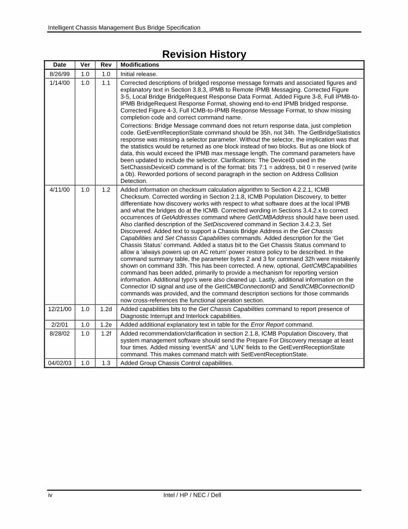
Revision History Date Ver Rev Modifications
8/26/99 1.0 1.0 Initial release. 1/14/00 1.0 1.1 Corrected descriptions of bridged response message formats and associated figures and
explanatory text in Section 3.8.3, IPMB to Remote IPMB Messaging. Corrected Figure 3-5, Local Bridge BridgeRequest Response Data Format. Added Figure 3-8, Full IPMB-to-IPMB BridgeRequest Response Format, showing end-to-end IPMB bridged response. Corrected Figure 4-3, Full ICMB-to-IPMB Response Message Format, to show missing completion code and correct command name. Corrections: Bridge Message command does not return response data, just completion code. GetEventReceptionState command should be 35h, not 34h. The GetBridgeStatistics response was missing a selector parameter. Without the selector, the implication was that the statistics would be returned as one block instead of two blocks. But as one block of data, this would exceed the IPMB max message length. The command parameters have been updated to include the selector. Clarifications: The DeviceID used in the SetChassisDeviceID command is of the format: bits 7:1 = address, bit 0 = reserved (write a 0b). Reworded portions of second paragraph in the section on Address Collision Detection.
4/11/00 1.0 1.2 Added information on checksum calculation algorithm to Section 4.2.2.1, ICMB Checksum. Corrected wording in Section 2.1.8, ICMB Population Discovery, to better differentiate how discovery works with respect to what software does at the local IPMB and what the bridges do at the ICMB. Corrected wording in Sections 3.4.2.x to correct occurrences of GetAddresses command where GetICMBAddress should have been used. Also clarified description of the SetDiscovered command in Section 3.4.2.3, Set Discovered. Added text to support a Chassis Bridge Address in the Get Chassis Capabilities and Set Chassis Capabilities commands. Added description for the ‘Get Chassis Status’ command. Added a status bit to the Get Chassis Status command to allow a ‘always powers up on AC return’ power restore policy to be described. In the command summary table, the parameter bytes 2 and 3 for command 32h were mistakenly shown on command 33h. This has been corrected. A new, optional, GetICMBCapabilities command has been added, primarily to provide a mechanism for reporting version information. Additional typo’s were also cleaned up. Lastly, additional information on the Connector ID signal and use of the GetICMBConnectionID and SendICMBConnectionID commands was provided, and the command description sections for those commands now cross-references the functional operation section.
12/21/00 1.0 1.2d Added capabilities bits to the Get Chassis Capabilities command to report presence of Diagnostic Interrupt and Interlock capabilities.
2/2/01 1.0 1.2e Added additional explanatory text in table for the Error Report command. 8/28/02 1.0 1.2f Added recommendation/clarification in section 2.1.8, ICMB Population Discovery, that
system management software should send the Prepare For Discovery message at least four times. Added missing ‘eventSA’ and ‘LUN’ fields to the GetEventReceptionState command. This makes command match with SetEventReceptionState.
04/02/03 1.0 1.3 Added Group Chassis Control capabilities.
Intelligent Chassis Management Bus Bridge Specification
Intel / HP / NEC / Dell v
Table of Contents 1. Introduction ............................................................................................................. 1
1.1 Audience ........................................................................................................................................... 2 1.2 Reference Documents ....................................................................................................................... 2 1.3 Conventions, Terminology, and Notation......................................................................................... 3 1.4 Scope................................................................................................................................................. 5 1.5 Background....................................................................................................................................... 5 1.6 Security ............................................................................................................................................. 6 1.7 Relationship to IPMI......................................................................................................................... 6 1.8 New Group Chassis Control Capabilities ......................................................................................... 6
2. ICMB Overview ........................................................................................................ 7 2.1 Usage Model ..................................................................................................................................... 7
2.1.1 Configurations........................................................................................................................... 7 2.1.2 ICMB Logical Devices.............................................................................................................. 8 2.1.3 Management Control Model.................................................................................................... 11 2.1.4 Software stack ......................................................................................................................... 11 2.1.5 ICMB Addresses ..................................................................................................................... 13 2.1.6 Address Assignment & Resolution ......................................................................................... 13 2.1.7 Address Collision Detection....................................................................................................14 2.1.8 ICMB Population Discovery ................................................................................................... 14 2.1.9 Events ...................................................................................................................................... 15 2.1.10 Cable Connection Determination ............................................................................................ 15 2.1.11 Chassis Function Requirements .............................................................................................. 16
2.2 Design Objectives ........................................................................................................................... 19 2.3 Design ............................................................................................................................................. 19
2.3.1 Scale ........................................................................................................................................ 21
3. Bridge Functional Specification........................................................................... 22 3.1 Bridge Classes................................................................................................................................. 22
3.1.1 Management Chassis Bridges.................................................................................................. 22 3.1.2 Peripheral Chassis Bridges...................................................................................................... 22
3.2 Bridge Addressing .......................................................................................................................... 22 3.2.1 IPMB Address ......................................................................................................................... 22
3.2.1.1 ICMB Bridge Proxy........................................................................................................... 23 3.2.2 ICMB Address......................................................................................................................... 23
3.3 Bridge State..................................................................................................................................... 23 3.4 Bridge Commands .......................................................................................................................... 24
3.4.1 Bridge Management Commands ............................................................................................. 24 3.4.1.1 Get Bridge State................................................................................................................. 24 3.4.1.2 Set Bridge State ................................................................................................................. 24
Intelligent Chassis Management Bus Bridge Specification
vi Intel / HP / NEC / Dell
3.4.1.3 Get ICMB Address ............................................................................................................ 24 3.4.1.4 Set ICMB Address............................................................................................................. 25 3.4.1.5 Get Bridge Statistics .......................................................................................................... 25 3.4.1.6 Clear Bridge Statistics ....................................................................................................... 26 3.4.1.7 Get ICMB Capabilities ...................................................................................................... 26 3.4.1.8 Set Bridge Proxy Address.................................................................................................. 26 3.4.1.9 Get Bridge Proxy Address................................................................................................. 27 3.4.1.10 Get ICMB Connector Info................................................................................................. 27 3.4.1.11 Get ICMB Connection ID.................................................................................................. 28 3.4.1.12 Send ICMB Connection ID ............................................................................................... 29
3.4.2 Bridge Chassis Commands...................................................................................................... 29 3.4.2.1 Prepare For Discovery ....................................................................................................... 30 3.4.2.2 Get Addresses .................................................................................................................... 30 3.4.2.3 Set Discovered................................................................................................................... 31 3.4.2.4 Get Chassis Device ID....................................................................................................... 31 3.4.2.5 Set Chassis Device ID ....................................................................................................... 31
3.4.3 Bridging Commands................................................................................................................ 32 3.4.3.1 Bridge Request .................................................................................................................. 32 3.4.3.2 Bridge Message ................................................................................................................. 32 3.4.3.3 Device Bridge Request ...................................................................................................... 33
3.4.4 Event Commands .................................................................................................................... 33 3.4.4.1 Send ICMB Event Message............................................................................................... 34 3.4.4.2 Set Event Destination ........................................................................................................ 35 3.4.4.3 Set Event Reception State.................................................................................................. 35 3.4.4.4 Get Bridge Event Count .................................................................................................... 35
3.5 Chassis Device Commands............................................................................................................. 36 3.5.1 Get Chassis Capabilities.......................................................................................................... 36 3.5.2 Get Chassis Status ................................................................................................................... 37 3.5.3 Chassis Control........................................................................................................................ 38 3.5.4 Chassis Reset........................................................................................................................... 38 3.5.5 Chassis Identify ....................................................................................................................... 39 3.5.6 Group Chassis Control ............................................................................................................ 39 3.5.7 Set Group Control Enables......................................................................................................42 3.5.8 Get Group Control Enables ..................................................................................................... 44 3.5.9 Get Control Group Settings.....................................................................................................45 3.5.10 Get Group Control Status ........................................................................................................ 47 3.5.11 Set Chassis Capabilities........................................................................................................... 49 3.5.12 Get POH Counter .................................................................................................................... 50
3.6 Group Chassis Control Operation................................................................................................... 50 3.6.1 DeviceBridgeRequest command ............................................................................................. 51 3.6.2 Group Chassis Control and PEF.............................................................................................. 51

Intelligent Chassis Management Bus Bridge Specification
Intel / HP / NEC / Dell vii
3.7 Bridge Events.................................................................................................................................. 51 3.7.1 ICMB Error ............................................................................................................................. 52 3.7.2 Receipt of ICMB Event ........................................................................................................... 52
3.8 Message Delivery............................................................................................................................ 53 3.8.1 IPMB to Local Bridge Messaging........................................................................................... 53 3.8.2 IPMB to Remote Bridge Messaging........................................................................................ 54 3.8.3 IPMB to Remote IPMB Messaging......................................................................................... 55 3.8.4 IPMI to Remote Device Messaging using DeviceBridgeRequest........................................... 57 3.8.5 ICMB Message Format ........................................................................................................... 58 3.8.6 Managing Remote Bridges...................................................................................................... 58
3.9 Address Assignment ....................................................................................................................... 58 3.9.1 Dynamic Assignment .............................................................................................................. 59 3.9.2 Address Collision Detection....................................................................................................59
3.10 Bridge API ...................................................................................................................................... 59 3.11 Bridge Performance and Capacity .................................................................................................. 60
3.11.1 Latency .................................................................................................................................... 60 3.11.2 Resource Utilization ................................................................................................................ 61
4. ICMB Datalink Protocol......................................................................................... 62 4.1 Bus States........................................................................................................................................ 62 4.2 Packet Framing and Packet Format ................................................................................................ 62
4.2.1 Framing ................................................................................................................................... 63 4.2.2 Packet Format.......................................................................................................................... 63
4.2.2.1 ICMB Checksum ............................................................................................................... 64 4.2.3 Bridged ICMB-to-IPMB Request Message............................................................................. 64 4.2.4 ICMB-to-IPMB Response Message ........................................................................................ 64 4.2.5 ICMB Event Message Format ................................................................................................. 65 4.2.6 IPMB Event Message for SMS ............................................................................................... 65
4.3 Arbitration and Collisions............................................................................................................... 66 4.3.1 Arbitration Protocol................................................................................................................. 66 4.3.2 Collision Behavior................................................................................................................... 69 4.3.3 Arbitration Pulse Generation...................................................................................................69
4.4 Connector ID Signal Generation..................................................................................................... 70 4.5 Performance .................................................................................................................................... 71 4.6 Interconnect Topologies.................................................................................................................. 71 4.7 ICMB Cabling Topology Determination ........................................................................................ 73
5. Bridge Command Summary ................................................................................. 76
6. Chassis Device Command Summary .................................................................. 79
7. Timing and Retry Specifications.......................................................................... 87

Intelligent Chassis Management Bus Bridge Specification
viii Intel / HP / NEC / Dell
8. Electrical Specifications ....................................................................................... 89 8.1 Optional Current Limit ................................................................................................................... 89 8.2 Failsafe Level.................................................................................................................................. 89 8.3 Common Mode Choke.................................................................................................................... 89 8.4 Series Termination .......................................................................................................................... 89 8.5 ICMB Transceiver Connections...................................................................................................... 89 8.6 Connector ID Interconnect Example............................................................................................... 90 8.7 Cable ............................................................................................................................................... 91 8.8 Connectors ...................................................................................................................................... 92
8.8.1 Type A Connector ................................................................................................................... 92 8.8.2 Type B Connector ................................................................................................................... 92
Appendix A. Bridging Operation - A ‘Memo’ Analogy............................................. 94
LAST PAGE.................................................................................................................. 96
List of Figures Figure 2-1, Simple ICMB Configuration...................................................................................................... 7 Figure 2-2, ICMB Logical Devices............................................................................................................... 8 Figure 2-3, Example Host System Management Bridge Implementation .................................................. 10 Figure 2-4, Example Peripheral Chassis Implementation........................................................................... 11 Figure 2-5, Typical Management Software Stack with ICMB ................................................................... 12 Figure 2-6, Sample ICMB Configuration Initialization.............................................................................. 13 Figure 2-7, ICMB/IPMB Network Topology ............................................................................................. 20 Figure 3-2, Internal IPMB Node to Bridge Request Message Format........................................................ 53 Figure 3-3, Bridge to Internal IPMB Node Response Message Format ..................................................... 53 Figure 3-4, IPMB-Remote Bridge BridgeRequest Command Data Format ............................................... 54 Figure 3-5, Local Bridge BridgeRequest Response Data Format............................................................... 55 Figure 3-6, IPMB-IPMB BridgeRequest Request Data Format ................................................................. 56 Figure 3-7, Full IPMB-to-IPMB BridgeRequest Request Format .............................................................. 56 Figure 3-8, Full IPMB-to-IPMB BridgeRequest Response Format............................................................ 57 Figure 3-8, IPMB to Remote Device Request Format................................................................................ 58 Figure 3-9, ICMB Bridge to Bridge Message Format ................................................................................ 58 Figure 4-1, ICMB Datalink Packet Format................................................................................................. 63 Figure 4-2, Full ICMB-to-IPMB Request Message Format ....................................................................... 64

Intelligent Chassis Management Bus Bridge Specification
Intel / HP / NEC / Dell ix
Figure 4-3, Full ICMB-to-IPMB Response Message Format..................................................................... 65 Figure 4-4, Full ICMB Event Message Format .......................................................................................... 65 Figure 4-5, IPMB Message to System Mgmt. Software for ICMB Events ................................................ 66 Figure 4-6, Arbitration Timing & Example ................................................................................................ 68 Figure 4-7, Connector ID Signal Timing.................................................................................................... 71 Figure 4-8, Passive Star Interconnect ......................................................................................................... 72 Figure 4-9, Daisy-chain Interconnect.......................................................................................................... 72 Figure 4-10, T-drop Interconnect................................................................................................................ 73 Figure 4-11, Get ICMB Connection ID, Send ICMB Connection ID example .......................................... 74 Figure 4-12, Identifiable Cabling Topologies............................................................................................. 75 Figure 8-1, Example ICMB Transceiver Circuit......................................................................................... 90 Figure 8-2, Example Connector ID Signal Connections............................................................................. 91
List of Tables
Table 1-1, Glossary....................................................................................................................................... 3 Table 1-2, Notation ....................................................................................................................................... 4 Table 2-1, Get Chassis Capabilities Command Fields Support Requirement............................................. 16 Table 2-2, Write-able FRU / SDR Support................................................................................................. 17 Table 3-1, ICMB Address Assignments ..................................................................................................... 23 Table 3-2, Device Selector Values.............................................................................................................. 33 Table 3-3, ICMB Event Codes.................................................................................................................... 34 Table 4-1, Framing Characters.................................................................................................................... 63 Table 5-1, ICMB Bridge Commands.......................................................................................................... 76 Table 6-1, Chassis Device Command Summary......................................................................................... 79 Table 7-1, General Timing Specicifications ............................................................................................... 87 Table 7-2, Arbitration Timing Specifications ............................................................................................. 88 Table 8-1, Type A Connector Pinout .......................................................................................................... 92 Table 8-2, Type B Connector Pinout .......................................................................................................... 93

Intelligent Chassis Management Bus Bridge Specification
x Intel / HP / NEC / Dell
Intelligent Chassis Management Bus Bridge Specification
Intel / HP / NEC / Dell 1
1. Introduction The Intelligent Chassis Management Bus (ICMB) defines a character-level transport for inter-chassis communications between intelligent chassis. This document defines the protocol and interface that is used to communicate with intelligent devices that manage those chassis. This includes the ability to use the ICMB to bridge messages from the Intelligent Platform Management Bus (IPMB) in one chassis to the IPMB in another.
Physically, the ICMB is a multi-drop, multi-master, 2-wire, half-duplex, differential drive bus, utilizing RS-485 transceivers. The intelligent devices using the IPMB and ICMB are typically microcontrollers that perform platform and chassis management functions such as servicing the front panel interface, monitoring system temperatures and voltages, controlling system power, etc. Intelligent devices may also be referred to in this document as ‘management controllers’ or just ‘controllers.’
The information contained within is organized as follows:
Chapter 1: Introduction This chapter describes the structure of this document, and provides motivation and background information on its creation.
Chapter 2: ICMB Overview This chapter gives an overview of ICMB architecture and usage model.
Chapter 2: Bridge Functional Specification This chapter describes bridge types, addressing and commands. It also discusses the encapsulation of bridge and IPMB messages.
Chapter 3: ICMB Datalink Protocol This chapter describes the packet format and bus protocol for the ICMB datalink protocol layer.
Chapter 5: Bridge Command Summary This chapter provides a summary of the bridge commands and their formats.
Chapter 6: Chassis Device Command Summary This chapter provides a summary of chassis device commands and their formats.
Chapter 7: Timing Specifications This chapter describes the specific timing requirements for the ICMB bridge; both at the bridging level as well as at the datalink level.
Chapter 8: Electrical Specifications This chapter describes the physical interface and provides the connector and electrical specifications for the ICMB.
Appendix A: Bridging Operation - A ‘Memo’ Analogy Presents an analogy targeted to assist the reader in understanding how message bridging works.

Intelligent Chassis Management Bus Bridge Specification
2 Intel / HP / NEC / Dell
1.1 Audience This document is written for engineers and system integrators involved in the design and programming of systems and software who use the Intelligent Platform Management Bus to communicate with remote management controllers or chassis that would be managed via the Intelligent Chassis Management Bus. It is assumed that the reader is familiar with PC and Intel server architecture and microcontroller devices. For basic and/or supplemental information, refer to the appropriate reference documents.
1.2 Reference Documents The following documents should be nearby when using this specification:
[1] IPMB v1.0 Address Allocation, ©1998, 1999 Intel Corporation, Hewlett-Packard Company, NEC Corporation, and Dell Computer Corporation. This document specifies the allocation of device addresses on the IPMB.
[2] Intelligent Platform Management Bus Communications Protocol Specification v1.0, ©1998 Intel Corporation, Hewlett-Packard Company, NEC Corporation, and Dell Computer Corporation. This document provides the electrical, transport protocol, and specific command specifications for the IPMB. The IPMB is used to communicate with and through an ICMB bridge.
[3] Intelligent Platform Management Interface Specification v1.5, © 1999, 2000, 2001, 2002 Intel Corporation, Hewlett-Packard Company, NEC Corporation, and Dell Computer Corporation. Describes the IPMB commands used to query the platform System Event Log (SEL), Sensor Data Record (SDR) repository, and FRU inventory devices.
[4] Platform Management FRU Information Storage Definition v1.0, ©1998, 1999 Intel Corporation, Hewlett-Packard Company, NEC Corporation, and Dell Computer Corporation. Provides the field definitions and format of Field Replaceable Unit (FRU) information.
Intelligent Chassis Management Bus Bridge Specification
Intel / HP / NEC / Dell 3
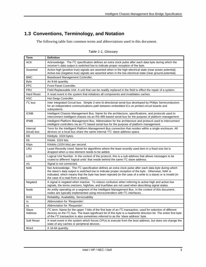
1.3 Conventions, Terminology, and Notation The following table lists common terms and abbreviations used in this document.
Table 1-1, Glossary
Term Definition ACK Acknowledge. The I2C specification defines an extra clock pulse after each data byte during which the
receiver’s data output is switched low to indicate proper reception of the byte. Asserted Active-high (positive true) signals are asserted when in the high electrical state (near power potential).
Active-low (negative true) signals are asserted when in the low electrical state (near ground potential). BMC Baseboard Management Controller. Byte An 8-bit quantity. FPC Front Panel Controller. FRU Field Replaceable Unit. A unit that can be readily replaced in the field to effect the repair of a system. Hard Reset A reset event in the system that initializes all components and invalidates caches. HSC Hot-Swap Controller. I2C bus Inter Integrated Circuit bus. Simple 2-wire bi-directional serial bus developed by Philips Semiconductors
for an independent communications path between embedded ICs on printed circuit boards and subsystems.
ICMB Intelligent Chassis Management Bus. Name for the architecture, specifications, and protocols used to interconnect intelligent chassis via an RS-485-based serial bus for the purpose of platform management.
IPMB Intelligent Platform Management Bus. Abbreviation for the architecture and protocol used to interconnect intelligent controllers via an I2C based serial bus for the purpose of platform management.
Internal (local) bus
Term for the Intelligent Platform Management Bus connection that resides within a single enclosure. All devices on a local bus share the same internal ‘I2C’ slave address space.
KB Kilobyte. 1024 bytes. Kb Kilobit. 1024 bits. Kbps Kilobits (1024 bits) per second. LRU Least Recently Used. Name for algorithms where the least recently used item in a fixed size list is
dropped when a new element needs to be added. LUN Logical Unit Number. In the context of the protocol, this is a sub-address that allows messages to be
routed to different ‘logical units’ that reside behind the same I2C slave address. n/c Signal is not connected. NAK Not Acknowledge. The I2C specification defines an extra clock pulse after each data byte during which
the slave’s data output is switched low to indicate proper reception of the byte. Otherwise, NAK is indicated, which means that the byte has been rejected (in the case of a write to a slave) or is invalid (in the case of a read from a slave).
Negated A signal is negated when inactive. To reduce confusion when referring to active-high and active-low signals, the terms one/zero, high/low, and true/false are not used when describing signal states.
Node An entity operating on a segment of the Intelligent Management Bus. In the context of this document, nodes are typically implemented using microcontrollers with I2C interfaces. .
RAS Reliability, Availability, Serviceability rs Abbreviation for ‘Responder’. rq Abbreviation for ‘Requester’. Slave Address
I2C term. Name for the upper 7-bits of the first byte of an I2C transaction, used for selection of different devices on the I2C bus. The least-significant bit of this byte is a read/write direction bit. The entire first byte of the I2C transaction is also sometimes referred to as the ‘slave address’ byte.
Soft Reset A reset event in the system which forces CPUs to execute from the boot address, but does not change the state of any caches or peripheral devices.
Word A 16-bit quantity.

Intelligent Chassis Management Bus Bridge Specification
4 Intel / HP / NEC / Dell
Table 1-2, Notation
Notation Definition brA XNA External Node Address for bridge ‘A’. A two-byte number that uniquely identifies the chassis (bridge
node) on the inter-chassis bus. brA LUN LUN for bridge node ‘A’ on the internal bus. brA SA Slave address of bridge node ‘A’ on the internal bus. brA seq The seq field for bridge node ‘A’. The bridge node sets this field when it generates a request. chk, checksum
16-bit checksum of all other bytes, except start and end characters, in an ICMB datalink packet. The ICMB checksum is the ones-complement of the sum of the packet bytes plus the overall packet length.
cmd, command
Command Byte(s) - one or more command bytes - as required by the network function.
data As required by the particular request or response. LUN The lower two bits of the netFn byte identify the logical unit number, which provides further sub-
addressing within the target node. netFn 6-bit value that defines the function within a target node to be accessed. The value is even if a
request, odd if a response. For example a value of 02h means a bridge request, 03h a bridge response. Refer to “Network Functions” below for more information.
seq Sequence field. This field is used to verify that a response is for a particular instance of a request. rq Abbreviation for ‘Requester’. rqBr SA Requester's Bridge Node's Slave Address. 1 byte. LS bit always 0. rq XNA Requester's External Node Address. 3 bytes. rqLUN Requester’s LUN. rqSA Requester's Slave Address. 1 byte. LS bit always 0. rs Abbreviation for ‘Responder’. rsBr SA Responder's Bridge Node’s Slave Address. 1 byte. LS bit always 0. rs XNA Responder's External Node Address. rsLUN Responder’s LUN. rsSA Responder's Slave Address. 1 byte. LS bit always 0. XX.YY Denotes the combination of netFn and CMD that is ultimately received at the node once any bridging
headers and LUN have been stripped off.

Intelligent Chassis Management Bus Bridge Specification
Intel / HP / NEC / Dell 5
1.4 Scope The bus and bridge subsystem defined in this document is the means by which an intelligent chassis management device communicates with another in a different chassis via a message-based inter-chassis bus called the ICMB (Intelligent Chassis Management Bus). The specification does not allow an intelligent device to directly access remote devices that do not implement the messaging protocol, such as a non-intelligent slave device that resides in a remote chassis.
1.5 Background The Intelligent Chassis Management Bus is a communication bus that is incorporated primarily into server platforms and peripheral chassis for the main purpose of ‘Inter-chassis Management’. Servers and other platforms incorporating this bus (collectively referred to in this document as ‘chassis’) can communicate with each other to provide access to monitoring and platform management features. This includes communicating information such as on board voltages, temperatures, fan rotation speed, processor and bus failures, FRU part numbers and serial numbers, etc., that can be used to improve the RAS characteristics of the systems.
The ICMB uses intelligent controllers (typically microcontrollers) that function independently of the system’s main processors. In addition, the controller and ICMB interface in each system is specified to stay powered while the main system is powered down. This allows status, control, and inter-chassis communications to remain functional under circumstances when the main processors are unavailable and when the system is powered down.
The Intelligent Chassis Management Bus architecture and protocol addresses several goals:
• Support a Distributed Management Architecture: A set of resources on an ICMB can be remotely discovered and managed. This allows for out-of-band management, or can be used to provide remote management functions even when the target is powered down.
• Support Remote Asynchronous Event Notification: A chassis can, depending on configuration, asynchronously notify system management agents of a condition warranting immediate attention.
• Provide an Extensible Platform Management Infrastructure: New resource (chassis) types can be added to or removed from an existing multi-chassis configuration. ICMB bridges do not interpret IPMB message traffic between nodes, they just handle the job of passing IPMB messages between intelligent controllers in the local and remote chassis. This de-couples ICMB-based access from the message semantics. This allows IPMB messages to be extended without requiring changes to the ICMB inter-chassis communication mechanism.
• Provide Multi-Master Operation: The Intelligent Chassis Management Bus implements multi-master operation, providing asynchronous messaging capabilities. This allows more than one system to access the bus without requiring coordination by a bus master function. Parties can interchange messages in an interleaved manner with other ICMB message interchanges. Broadcast is supported for event notification and chassis discovery support.
• Support ‘Out-of-Band’ Access to Platform Management Information: It is possible for the remote platform’s IPMB resources to be accessed by an autonomous system management card that allows the management data to be delivered to a remote console via a phone line or LAN connection. The ICMB extends the potential usefulness of such a management card by providing an inter-chassis communication path from the IPMB.
Intelligent Chassis Management Bus Bridge Specification
6 Intel / HP / NEC / Dell
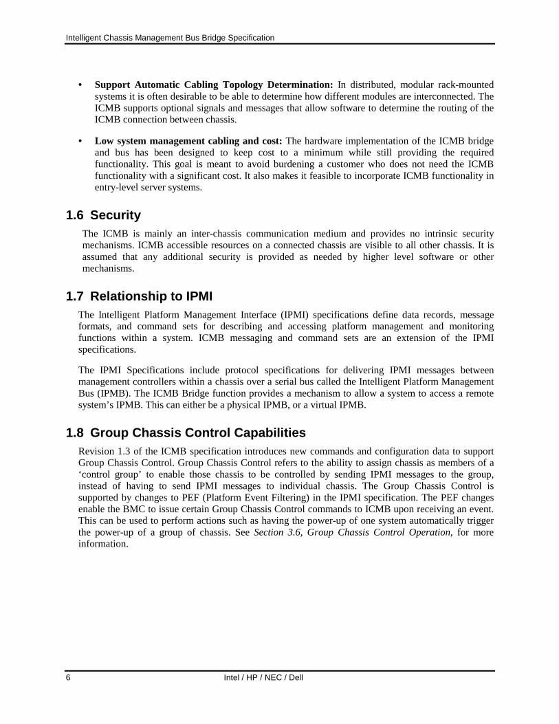
• Support Automatic Cabling Topology Determination: In distributed, modular rack-mounted systems it is often desirable to be able to determine how different modules are interconnected. The ICMB supports optional signals and messages that allow software to determine the routing of the ICMB connection between chassis.
• Low system management cabling and cost: The hardware implementation of the ICMB bridge and bus has been designed to keep cost to a minimum while still providing the required functionality. This goal is meant to avoid burdening a customer who does not need the ICMB functionality with a significant cost. It also makes it feasible to incorporate ICMB functionality in entry-level server systems.
1.6 Security The ICMB is mainly an inter-chassis communication medium and provides no intrinsic security mechanisms. ICMB accessible resources on a connected chassis are visible to all other chassis. It is assumed that any additional security is provided as needed by higher level software or other mechanisms.
1.7 Relationship to IPMI The Intelligent Platform Management Interface (IPMI) specifications define data records, message formats, and command sets for describing and accessing platform management and monitoring functions within a system. ICMB messaging and command sets are an extension of the IPMI specifications.
The IPMI Specifications include protocol specifications for delivering IPMI messages between management controllers within a chassis over a serial bus called the Intelligent Platform Management Bus (IPMB). The ICMB Bridge function provides a mechanism to allow a system to access a remote system’s IPMB. This can either be a physical IPMB, or a virtual IPMB.
1.8 Group Chassis Control Capabilities Revision 1.3 of the ICMB specification introduces new commands and configuration data to support Group Chassis Control. Group Chassis Control refers to the ability to assign chassis as members of a ‘control group’ to enable those chassis to be controlled by sending IPMI messages to the group, instead of having to send IPMI messages to individual chassis. The Group Chassis Control is supported by changes to PEF (Platform Event Filtering) in the IPMI specification. The PEF changes enable the BMC to issue certain Group Chassis Control commands to ICMB upon receiving an event. This can be used to perform actions such as having the power-up of one system automatically trigger the power-up of a group of chassis. See Section 3.6, Group Chassis Control Operation, for more information.
Intelligent Chassis Management Bus Bridge Specification
Intel / HP / NEC / Dell 7
2. ICMB Overview 2.1 Usage Model
The ICMB is designed for providing access to common chassis inventory, remote control, and status functions under conditions where that information may not be able to be obtained through in-band channels (e.g., a LAN). This could be either because the information is not provided through those channels or because the in-band channels are not available, e.g., when the chassis powered down. Thus, ICMB is a complementary technology to in-band system management standards, such as DMI, SNMP, and CIM, and peripheral management standards, such as SAF-TE and SES.
ICMB provides a means to do emergency management and diagnosis of servers and peripheral chassis. It also provides a mechanism for doing an inventory of systems and chassis. The ICMB bridge and “Front Panel” functionality are meant to be connected to the power subsystem standby power, allowing access to the chassis information, emergency management status, and power control, even if the server or peripheral chassis is powered down. ICMB functionality is not required to be available for servers without AC power. I.e. there is no mandatory requirement for battery backup.
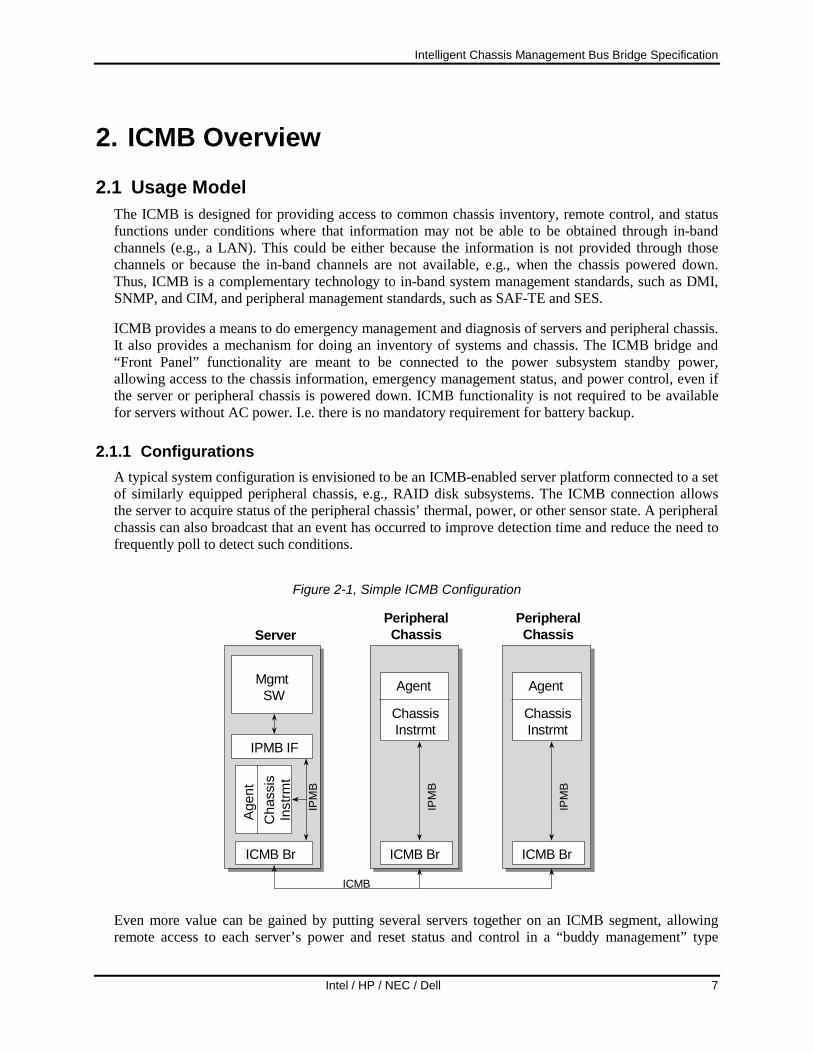
2.1.1 Configurations A typical system configuration is envisioned to be an ICMB-enabled server platform connected to a set of similarly equipped peripheral chassis, e.g., RAID disk subsystems. The ICMB connection allows the server to acquire status of the peripheral chassis’ thermal, power, or other sensor state. A peripheral chassis can also broadcast that an event has occurred to improve detection time and reduce the need to frequently poll to detect such conditions.
Figure 2-1, Simple ICMB Configuration
Mgmt SW
IPMB IF
ICMB Br
Server
IPM
B
ICMB
Cha
ssis
Inst
rmt
Agen
t
ICMB Br
ChassisInstrmt
PeripheralChassis
IPM
B
Agent
ICMB Br
ChassisInstrmt
PeripheralChassis
IPM
B
Agent
Even more value can be gained by putting several servers together on an ICMB segment, allowing remote access to each server’s power and reset status and control in a “buddy management” type

Intelligent Chassis Management Bus Bridge Specification
8 Intel / HP / NEC / Dell
configuration. Unless power is lost to all connected servers, the ICMB-based access should always be available and diagnosis and recovery from many kinds of failures are possible.
A more complex system (a cluster) might include multiple servers and a set of peripheral chassis in a shared resource configuration. The ICMB can be used to increase overall system availability by allowing the servers in the cluster to have access to more powerful recovery mechanisms (remote power and reset control) than normally available.
2.1.2 ICMB Logical Devices An ICMB-managed chassis can be viewed as a number of logical devices that encapsulate specific functions. These logical devices may be physically implemented using separate management controllers, or may be aggregated into a single, central controller. These logical devices are illustrated in Figure 2-2, below.
Figure 2-2, ICMB Logical Devices
IPMB
SEL(system event
log)
SDRRepository
Status &Control
ICMB
Sensors
ICMB BridgeDevice
ChassisDevice
SELDevice
Mgmt.Controller
SDRRepository
Device
ChassisFRU
Device
The following is a description of the different types of logical devices and other elements shown in Figure 2-2.
• ICMB Bridge Device: Typically referred to as the ‘ICMB bridge’ or just ‘bridge’, this device provides the mechanism for transferring messages between the ICMB and devices on the IPMB. The bridge functionality includes commands that support chassis discovery and address resolution on the ICMB. The ICMB Bridge also holds information that allows a remote system to get the IPMB address of the Chassis Device.
• Chassis Device: This device is the starting point for accessing the management functions in the chassis. The chassis device includes a set of base management functions, such as power control and overall health status. The chassis device also provides commands that allow a remote system to get the addresses of other logical devices, such as the SDR Repository, SEL, and Chassis FRU devices.
• SDR Repository Device: This device holds IPMI Sensor Data Records (SDRs). Sensor Data Records hold information that describes the population of monitoring sensors and management controllers that are accessible via the IPMB.

Intelligent Chassis Management Bus Bridge Specification
Intel / HP / NEC / Dell 9
• Management Controller: A managed chassis will typically include sensors for monitoring chassis conditions such as internal temperatures, supply voltages, etc. Access to sensors is obtained by sending commands to a management controller. Multiple management controllers can reside on an IPMB. A remote application reads the SDRs to find out what management controllers and sensors are present. A special management controller, referred to as the SM (System Management) Device in this document, provides a gateway between the IPMB and system management software. This device is the BMC in IPMI-based host systems.
• SEL Device: This device provides access to a non-volatile log that holds platform event records.
• Chassis FRU Device: This device holds information about the chassis as a FRU (Field Replaceable Unit). This can include serial number, part number, model name, asset tag, and other information.
The various logical device functions are shown as being connected to an IPMB. This may be a physical IPMB or a virtual IPMB. A physical IPMB is two-wire serial bus that includes a particular set of protocols governing how devices are addressed on the bus and how request and response messages are formatted. The IPMB includes data integrity checking in the form of message checksums, and a retry mechanism for data error recovery.
The ICMB was designed to support one Bridge, Chassis, SEL, SDR, Chassis FRU, and System Management Device per chassis. The design of systems with additional or redundant devices is beyond the scope of this specification.
The ICMB bridge provides a way for a system to generate requests to and receive responses from devices on a remote IPMB. To the devices on the remote IPMB, these messages appear just as if the bridge directly generated them locally.
In order to accomplish this, ICMB messages for accessing devices on a remote IPMB include data that allows the bridge to create a message that can be routed to a particular device on the IPMB.
A physical implementation of an IPMB is not required for an ICMB managed system. A system that generates messages to a remote system via the ICMB only cares that the remote system responds to as if there were an IPMB in the system. From the ICMB view, it doesn’t matter whether the logical devices are implemented on a physical incarnation of an IPMB or not.
Figure 2-3 shows one possible implementation of the ICMB in a host system. In this example, the ICMB interface is implemented as an option card for a system that has an IPMI-based platform management subsystem that contains an IPMB, a BMC, and a Satellite Management Controller. The BMC (baseboard management controller) provides the SEL Device and SDR Repository Device functions, while the ICMB Controller provides the bridge and chassis device functions. Management controller functions (sensor monitoring) are made available from both the BMC and Satellite controllers.
The term Management Bridge is used to refer to an ICMB bridge in a host system that supports system management software access to the ICMB via an IPMI BMC. The term Peripheral Bridge is used to refer to a bridge in a peripheral chassis that provides ICMB, chassis status/control, and bridging functions. Management Bridge functionality is a superset of the Peripheral Bridge functionality.

Intelligent Chassis Management Bus Bridge Specification
10 Intel / HP / NEC / Dell
The BMC also provides the path for messages between system software and the IPMB. Since the bridge allows messages to be transferred between the IPMB and ICMB, the BMC and bridge together form a path for messages between system software and the ICMB.
Figure 2-4 shows a possible implementation of the ICMB in a peripheral chassis. In this example, all management functions, including the ICMB interface, are integrated into a single microcontroller. The example shows that this microcontroller is also used for providing in-band management functions via the SCSI interface to the chassis.
Figure 2-3, Example Host System Management Bridge Implementation
System Chassis
Drive BackplaneBaseboard
BMC
SatelliteMgmt.
ControllerSensorsSELSDR RepositoryBaseboard FRU
Non-volatile Storage
Sensors
ICMB Card
System Bus
IPMB
ICMB
ICMBController
FRUSEEPROM
Chassis FRU

Intelligent Chassis Management Bus Bridge Specification
Intel / HP / NEC / Dell 11
Figure 2-4, Example Peripheral Chassis Implementation
Peripheral Chassis
Management Board
Chassis ManagementController ICMB
Bridge
SELDevice
SDRRepository
Device
ChassisFRU
Device
ChassisDevice
Mgmt.Controller
SCSIInterface
NV Storage Interface
SCSI
ICMB
! SEL! SDR Repository! Chassis FRU Info.! OEM Parameters
Non-volatile Storage
Sensors
Virtual IPMB
2.1.3 Management Control Model The expected bus management model is for only one ICMB connected server to be managing a bus segment for control, such as power control, at any particular time. For example, although other servers may be attached to the segment, only one will have the responsibility of responding to ICMB-based events and providing them to any higher-level system or enterprise-level management software. It is beyond the scope of this document to specify how the managing server is chosen or what occurs if that server fails, i.e. system fail-over behavior.
2.1.4 Software stack At the top of the software management stack of which ICMB is a part, is a management console application that provides the system administrator/operator views of system state and notification of various types of system events that might affect system operation or reliability. This console may be providing such information and services for several systems simultaneously.

Intelligent Chassis Management Bus Bridge Specification
12 Intel / HP / NEC / Dell
Figure 2-5, Typical Management Software Stack with ICMB
Management Application(e.g. Management Console)
Platform Instrumentation
Embedded PlatformInstrumentation(e.g. IPMI BMC)
OS-residentsoftware
Platform-resident
firmware/hardware
ICMB BridgeRemote access to platfor mmanagement via ICM B
Local or r emote access to platfor m managemevia OS-supported c omm unication paths
At the next level down is the per-system instrumentation software that interprets the system platform state (e.g., temperature, critical events) and provides a view of it to the console above. The instrumentation software accepts queries and commands from the console related to that state. The console application may be resident on the same system as the instrumentation software, but more typically is communicates with the instrumentation software on a remote system via the system’s normal networking paths.
The next level is the embedded platform instrumentation. This instrumentation operates independently of the platform’s main processors and is usually responsible for low-level aspects of booting, power management, and fault detection. On high-availability server platforms, some subset of this functionality (including the ICMB and power management) is available even when system power is off. The embedded platform instrumentation is commonly implemented with custom logic and/or a microcontroller.
In present IPMI-based systems, one or more management controllers form the heart of the embedded instrumentation functions. For these systems, the embedded instrumentation can be thought of as the combination of the platform management hardware, the management controllers, and the management controller firmware.
The ICMB fits into the system management software stack as a transport to access the embedded instrumentation on remote chassis. An ICMB segment’s managing server(s) hosts proxy component instrumentation, at the per-system instrumentation level, for the remotely accessed instrumentation.
An ICMB bridge is a passive device. It responds to activity directed to it on either of its two ports (IPMB, ICMB). Information about the chassis of which it is a part (such as the chassis capabilities) is provided by a chassis based agent outside of the bridge proper.
Intelligent Chassis Management Bus Bridge Specification
Intel / HP / NEC / Dell 13
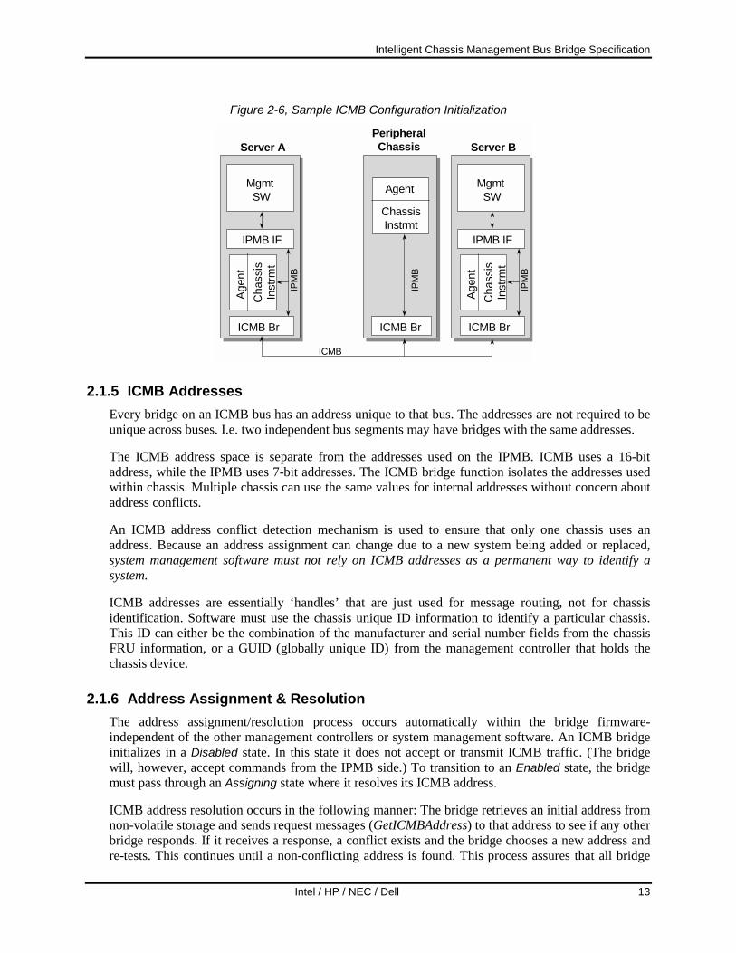
Figure 2-6, Sample ICMB Configuration Initialization
Mgmt SW
IPMB IF
ICMB Br
Server A
ICMB Br
ChassisInstrmt
PeripheralChassis
Mgmt SW
IPMB IF
ICMB Br
Server B
IPM
B
IPM
B
ICMB
Cha
ssis
Inst
rmt
Agen
t
IPM
B
Agent
Cha
ssis
Inst
rmt
Agen
t
2.1.5 ICMB Addresses Every bridge on an ICMB bus has an address unique to that bus. The addresses are not required to be unique across buses. I.e. two independent bus segments may have bridges with the same addresses.
The ICMB address space is separate from the addresses used on the IPMB. ICMB uses a 16-bit address, while the IPMB uses 7-bit addresses. The ICMB bridge function isolates the addresses used within chassis. Multiple chassis can use the same values for internal addresses without concern about address conflicts.
An ICMB address conflict detection mechanism is used to ensure that only one chassis uses an address. Because an address assignment can change due to a new system being added or replaced, system management software must not rely on ICMB addresses as a permanent way to identify a system.
ICMB addresses are essentially ‘handles’ that are just used for message routing, not for chassis identification. Software must use the chassis unique ID information to identify a particular chassis. This ID can either be the combination of the manufacturer and serial number fields from the chassis FRU information, or a GUID (globally unique ID) from the management controller that holds the chassis device.
2.1.6 Address Assignment & Resolution The address assignment/resolution process occurs automatically within the bridge firmware-independent of the other management controllers or system management software. An ICMB bridge initializes in a Disabled state. In this state it does not accept or transmit ICMB traffic. (The bridge will, however, accept commands from the IPMB side.) To transition to an Enabled state, the bridge must pass through an Assigning state where it resolves its ICMB address.
ICMB address resolution occurs in the following manner: The bridge retrieves an initial address from non-volatile storage and sends request messages (GetICMBAddress) to that address to see if any other bridge responds. If it receives a response, a conflict exists and the bridge chooses a new address and re-tests. This continues until a non-conflicting address is found. This process assures that all bridge

Intelligent Chassis Management Bus Bridge Specification
14 Intel / HP / NEC / Dell
addresses on an ICMB segment are unique. Additional information on the address resolution process is provided in the command specifications given in later sections.
Once a bridge has an address, it becomes passive with respect to the ICMB-with the exception that it will periodically broadcast Chassis Online ICMB events. (This mechanism helps to expedite chassis discovery by proactively announcing the chassis existence.) Otherwise, the bridge will not autonomously generate requests.
A bridge will not accept bridging commands (commands to bridge messages between the ICMB and IPMB) until it has been discovered (see following section). This is to further reduce the possibility of confusion or wrong behavior due to ICMB address collisions.
2.1.7 Address Collision Detection It is possible, though unlikely, that two bridges on the same bus segment could wind up with the same address. For example, this could occur when a new chassis is connected to the bus. This can cause confusion if commands to one chassis are intercepted and acted on by another. To help avoid this, bridges continuously check for address collisions during operation.
Each bridge watches incoming packets and checks to see if the source address is the same as its own. If a bridge receives a Get ICMB Address command and both the source and destination addresses are its own; the bridge will process the command normally and send a response back to its own address. This is the way a bridge must respond when another bridge probes to see if its address is already in use. Otherwise, if the source address is its own, it will immediately stop accepting command packets and re-initialize itself, going through the address assignment phase again. If its address changes due to this process, the new address will be discovered by system management software during the next discovery cycle. (This is another reason why system management software should not use the ICMB address as the unique ID for a given system.)
2.1.8 ICMB Population Discovery The ICMB protocol is designed to allow for dynamic discovery of a bus segment’s population. No manual identification or manual configuration is necessary. The ICMB discovery process is driven from the system management software level. The ICMB bridge just provides the basic mechanisms to support discovery of a bus segment’s chassis population.
1. The management software first sends a PrepareForDiscovery to its local bridge. This causes the broadcast of a PrepareForDiscovery message over the ICMB to prepare the bus’ population for a discovery cycle. This command places the bridges into an ‘undiscovered’ state (with respect to the sending bridge1) where they will respond to the GetICMBAddress message. (The management software should send the Prepare for Discovery message at least four times to ensure that all bridges get the message.)
1 In order to better handle more than one system simultaneously performing a discovery, it is recommended, but not required, that the bridge maintains separate discovered/undiscovered state for at least four different sources. That is, the bridge tracks the source address of the requester for the PrepareForDiscovery command, and handles subsequent SetDiscovered and GetICMBAddress commands based on that address. The implementation must allow for an indefinite number of different sources of the PrepareForDiscovery command over time. One approach to meeting this requirement would be to maintain a list that tracks the requesters that have issued the SetDiscovered message and use a round-robin or LRU algorithm to replace entries in the list if it gets full.

Intelligent Chassis Management Bus Bridge Specification
Intel / HP / NEC / Dell 15
2. The management software then sends a GetAddresses command to its local bridge which causes a GetICMBAddress message to be broadcast, requesting all the chassis on the bus to identify themselves. Multiple chassis will try to simultaneously respond, but arbitration mechanisms ensure that this will turn into a stream of responses from different chassis on the bus. (Individual bridges try until they successfully arbitrate and transmit their GetICMBAddress response on the bus once.)
3. The sending bridge collects a number of the responses from other chassis on the bus and forwards them to the management software in its response. As the chassis bridges are identified, they are individually sent a SetDiscovered message by the management software. This causes them to ignore further GetICMBAddress messages from that source, and to stop sending ChassisOnline events. A bridge will not accept any bridging commands until it has received at least one Set Discovered command after entering the Enabled state.
4. This process iterates (steps 2 and 3), the management software sending GetAddresses messages to its local bridge and “you’ve been discovered” request messages (SetDiscovered message) until no more chassis respond to the GetICMBAddress commands. (The GetICMBAddress command is retried a number of times to ensure that all chassis get the message.)
At this point, the management software has discovered all the chassis on the ICMB as identified by their ICMB chassis addresses.
This process is repeated periodically by management software in order to maintain an up-to-date inventory of the bus’ population. For example, to detect chassis that have gone off-line.
Discovering the existence of a chassis is only one aspect of the total discovery process. In order to be able to manage a chassis, the management software needs to know what kind of chassis it is. The ICMB bridge protocol provides a mechanism for a chassis to export its FRU and other information for this purpose. See Section 2.1.11, Chassis Function Requirements, for more details.
2.1.9 Events A chassis can request service from the managing server by sending ICMB events. These are unacknowledged messages that are, by default, broadcast on the ICMB. Only recipients that care about such messages (typically only the managing server) will process them. All others will ignore them. Since the event messages are unacknowledged, to guarantee service, a chassis may periodically re-send them until the managing server has cleared or otherwise acknowledged the triggering condition. The ICMB management software should periodically poll chassis to determine if an event has occurred.
2.1.10 Cable Connection Determination ICMB includes the specification of optional point-to-point Connector ID signals and associated commands that can be used to determine which connectors are being used to interconnect systems and chassis. Details on the operation and use of these commands is given in Section 4.7, ICMB Cabling Topology Determination. The commands themselves and the signals are specified in Section 3.4.1, Bridge Management Commands, and Section 4.4, Connector ID Signal Generation, respectively.

Intelligent Chassis Management Bus Bridge Specification
16 Intel / HP / NEC / Dell
2.1.11 Chassis Function Requirements Once a chassis has been discovered by management software, that software needs to further discover the type and state of that chassis. It does this by getting the chassis FRU inventory information and power and event state. In order to allow this to be done in a uniform way, every chassis must implement a Chassis Device that responds to a small set of generic chassis functions targeted to the IPMB Chassis network function.
An ICMB bridge provides a mechanism to discover the IPMB address of the Chassis Device via its GetChassisDevice command. Once the Chassis Device has been identified, the GetChassisCapabilities command can be used to obtain the IPMB addresses of other devices, such as the FRU Inventory Device.
The Chassis Device in an ICMB managed chassis must meet the following requirements to fully participate in the ICMB architecture. The following list presents an overview of the required functions, but is not intended to be a complete specification of required commands, please refer to the command descriptions and command tables later in this document. In particular, refer to Section 3.5, Chassis Device Commands, for additional information.
• Get Chassis Capabilities command. It must implement a GetChassisCapabilities command in order to provide for discovery of the chassis FRU Inventory Device, SDR Device, and other devices. The capabilities represent a handle to acquire more information about the type and internal state of the chassis. The capabilities are a set of fields that describe how to further determine the chassis type and identity. Currently there are four fields defined, only one value is required for every chassis and the others are optional:
Table 2-1, Get Chassis Capabilities Command Fields Support Requirement
Field Value Req’d/Opt Capabilities Flags Bit field indicating which chassis status are provided Required Chassis FRU Inventory Device Address
The IPMB address of the node providing this service. Required
Sensor Data Record Repository Device Address
The IPMB address of the node providing this service. Required[1]
System Event Log Device Address
The IPMB address of the node providing this service. Required
System Management Device Address
The IPMB address of the node providing this service. Required[2]
Chassis Bridge Device The IPMB address of the node providing the Chassis Bridge
Optional[3]
1. Required if chassis implements IPMI sensor commands or FRU devices at other than FRU device identified by the Chassis FRU Inventory Device Address. (see detailed description, below)
2. Required if chassis supports a device that forwards messages from IPMB to system software via it’s LUN 10b. In most cases, this means a chassis that incorporates a BMC.
3. Implementing this field is required when the Get Chassis Capabilities command is implemented by a BMC, and whenever the Chassis Bridge function is implemented at an address other than 20h. If this field is not provided, the BMC address, 20h, is assumed.
• Chassis FRU Inventory Device. It must implement a FRU Inventory Device for the chassis and respond to IPMB Read FRU Inventory Device and Get FRU Inventory Area info commands over the ICMB. It must advertise the address of this device via the Chassis GetChassisCapabilities command. This device must be implemented as FRU Device ID 0 at LUN 00b at the specified

Intelligent Chassis Management Bus Bridge Specification
Intel / HP / NEC / Dell 17
address. This device must include a Chassis Info Area per the IPMI Platform Management FRU Storage The FRU Inventory Area contains the product and chassis serial number, model, type and other data by providing a Chassis Info Area and Product Info Area as specified in the IPMI Platform Management FRU Information Storage Definition specification.
• Sensor Data Record Repository Device. It should implement a Sensor Data Record (SDR) Device and respond to the IPMB SDR access commands over the ICMB. The Sensor Data Record Repository provides a discovery mechanism for internal sensors for parameters such as temperature and voltage. Implementing an SDR Device is mandatory if the chassis implements IPMI commands for retrieving sensor readings or event status. The SDR Device is also required if there are IPMI-accessed FRU Devices present other than the device located by the Chassis FRU Inventory Address from the GetChassisCapabilities command. If an SDR Device is present, it’s IPMB address must be advertised via the ChassisGetChassisCapabilities command.
• Writable FRU and SDR Repository Device Support. Support for writing to the FRU devices and writing and clearing SDRs is mandatory for BMCs, but optional for peripheral chassis and power bays. This provision is to reduce the non-volatile storage required for implementing peripheral chassis and power bays. It is highly recommended that chassis Asset Tag field in the Product Info Area of the FRU is write-able in order to allow the asset tag field to be updated via ICMB.
Note that the IPMI specification may call out that support for SDR Write and FRU Write are mandatory. This specification supercedes that requirement for FRU and SDR Repository devices used in Peripheral Chassis Controller applications. This specification does not supercede any IPMI specification requirements for BMCs.
Table 2-2, Write-able FRU / SDR Support
Peripheral Chassis
Controller
BMC
SDR write optional Mandatory FRU write optional Mandatory
• System Event Log Device. It must implement a 16-entry (minimum) System Event Log Device and respond to the mandatory IPMB SEL Device commands over the ICMB with the exception that peripheral chassis are not required to implement the Add and Partial Add SEL commands. (Note, support for these commands is recommended to enable testing of the event log via ICMB.) A peripheral chassis controller is also not required to be an IPMB Event Receiver. This means that the controller is not required to accept the IPMI Platform Event request message (a.k.a. “Event Message”) either internally or bridged in via ICMB. The System Event Log provides a history of critical events experienced by the chassis and can be of great use in diagnosing chassis problems. It should advertise its SEL Device IPMB address via the Chassis GetChassisCapabilities command.
• System Management Device. Host systems should implement a System Management Device (typically a BMC). This device provides access to the chassis System Management software, allowing peer-to-peer management communication over the ICMB. This is the BMC for IPMI-based host systems. It should advertise its SM Device IPMB address via the Chassis

Intelligent Chassis Management Bus Bridge Specification
18 Intel / HP / NEC / Dell
GetChassisCapabilities command. A System Management Device must accept IPMB messages to LUN 10b and forward those messages to system software.
• Chassis Control command. A peripheral controller chassis device must provide a ChassisControl command that can be used to turn on, off, or cycle chassis DC power. This is optional for a management bridge.
• Chassis Reset command. A chassis device may also provide a ChassisReset command to allow chassis logic (excluding the chassis device itself) to be reset. For host systems, this corresponds to a system hard reset.
• Chassis Identify command. A chassis device should provide a ChassisIdentify command that will cause the chassis to physically identify itself by blinking user-visible lights or emitting beeps via a speaker, etc.
• Get Chassis Status command. It must implement a Chassis GetChassisStatus command, providing information on the chassis power and security state. The main goal being to present any status relating to any condition that would prevent the chassis from being powered up, or to indicate a condition where caution may be advised. This status command provides the following chassis status:
Current Power State This describes the current state of chassis DC power.
- DC power is ON - DC power is OFF, because one of the following:
♦ Power Fault Failure in power subsystem. ♦ Power Control Fail Failure in power control mechanism ♦ Power Overload Power consumption out of spec ♦ Over-Temperature Condition Failed chassis cooling ♦ Chassis Interlock Removed side panels
Last Power Event
This describes the last event that affected chassis power state: ♦ Power Fault Failure in power subsystem. ♦ Power Control Fail Failure in power control mechanism ♦ Power Overload Power consumption out of spec ♦ AC Fail Mains power failure ♦ Chassis Interlock Removed side panels ♦ Power Commanded Up/Down User/Software initiated action
Restore Power State
This describes the current policy with respect to restoring DC power to the previous state after AC power has been restored after an outage. The policy options are:
♦ Apply previous DC power state on AC restore ♦ Do not apply DC power on AC restore ♦ Always power up on AC restore

Intelligent Chassis Management Bus Bridge Specification
Intel / HP / NEC / Dell 19
Chassis Physical Security State This describes the state of chassis door switch(es).
♦ Intrusion switch(es) Open ♦ Intrusion switch(es) Closed
2.2 Design Objectives The basic design of the ICMB protocol conforms to the following objectives and principles:
• Design for efficient implementation by controllers with limited processing capability and limited RAM and ROM resources. Potentially complex or processing-intensive functions are relegated to the higher-level management software running on the host processor.
• Exhibit a high degree of symmetry, for example: the method of accessing a chassis should be independent from the chassis type (i.e. whether the chassis is a server or peripheral ).
• Exhibit clean layering of functionality, for example: messages (application data) are not mixed with protocol data, and different aspects of protocol data are similarly kept separate.
2.3 Design The ICMB design can be viewed from the perspective of the standard ISO network reference model. It consists of the following layers:
• Physical Layer The ICMB physical layer is a multi-drop, multi-master, bus-based on RS-232 signaling (i.e. standard UART character framing) over RS-485 electrical transmission. It has been designed to be as compatible as possible with standard and commonly used hardware. This is to allow not only ICMB bridges, but also other agents such as PCs (dedicated or portable) to be connected to the bus with a minimum of special hardware. It is expected that such agents will be useful to debug and diagnose ICMB implementations and installations. The bus is a broadcast medium; all receivers on it see the same bus state and transitions. The bus is biased to the high (1) state when not explicitly driven by a bridge. The bus state when multiple bridges are driving it is undefined and depends on the states the bridges are trying to drive it to and the relative strengths of the bridge’s drivers.
• Datalink Layer Information is transmitted over the ICMB in packets. This layer defines packet framing and format, bridge addressing, and bus arbitration. It implements an unreliable datagram transmission service. I.e. no guarantees are made to the higher levels that the packet will arrive at its destination. Also, there is no flow control. If more packets arrive than there are resources to deal with, the packets will be dropped. The current design calls for a 19.2 Kbps character transmission rate with 8-bit characters, no parity, 1 stop bit. Framing is done with distinguished characters and those characters are escaped if they occur in the packet proper. Each packet includes a checksum for data integrity checking. See Chapter 4. ICMB Datalink Protocol for more details.

Intelligent Chassis Management Bus Bridge Specification
20 Intel / HP / NEC / Dell
Figure 2-7, ICMB/IPMB Network Topology
Server B
Inte
llige
nt C
hass
is M
anag
emen
t Bus
(IC
MB)
BridgeNodeIntelligent Platform Mgt. Bus (IPMB)
IntelligentNodes
Intelligent Chassis Mgt. Bus
IntelligentDevice 2
IntelligentDevice 1
Server A
BridgeNodeIntelligent Platform Mgt. Bus (IPMB)
IntelligentNodes
Intelligent Chassis Mgt. Bus
IntelligentDevice 2
IntelligentDevice 1
Peripheral Chassis C
VIRTUAL Intelligent Platform Mgt. Bus (IPMB)
IntelligentNodes
Intelligent Chassis Mgt. Bus
VirtualIntelligentDevice 2
VirtualIntelligentDevice 1
BridgeNode
• Network Layer This layer is NULL in the current ICMB design. No routing functions are defined. If more than one bridge per chassis were allowed (to connect to multiple ICMB segments), then this layer would provide the functions to route between the segments.
• Transport Layer The transport layer provides for the encapsulation and delivery of IPMB messages from the IPMB of one chassis to the IPMB of a second chassis. It is also possible to direct a request to a remote bridge, as opposed to a node on the remote bridge’s IPMB. An IPMB request to be remotely executed is given to the local ICMB bridge, which then transports it to the remote bridge via the ICMB. The remote bridge then sends the request to the indicated responder on its IPMB as if the request were locally generated. The corresponding response is likewise transported by the remote bridge back to the originating bridge, which then forwards it to the requester via the IPMB. See Chapter 3: Bridge Functional Specification for more details.
• Session Layer Although an ICMB bridge does not perform session layer activities directly, it provides functions that facilitate them. Those functions can be classified into a single basic area: discovery. The ICMB protocol provides for dynamic discovery of the set of chassis connected to an ICMB segment. Two types of information can be directly discovered about a chassis:
♦ The ICMB address of its bridge. This is used to direct ICMB traffic to the chassis.

Intelligent Chassis Management Bus Bridge Specification
Intel / HP / NEC / Dell 21
♦ Its Chassis Device IPMB address. This is used to further determine what kind of chassis it is and what its status is by querying its Chassis Device. Every ICMB capable chassis is required to implement a Chassis Device that indirectly provides access to the chassis FRU inventory area via the ICMB. This allows management software on the managing chassis to determine the chassis type and so know how to manage it.
To participate in inter-chassis Management Bus communication, a chassis provides an intelligent device that acts as the bridge node. A bridge node contains Intelligent Management Bus ports for connection to both the external and I2C networks. Only intelligent devices, typically bridge nodes, reside on this inter-chassis bus, through which multiple servers and peripheral chassis are joined into a single Intelligent Management Bus domain. Figure 2-7 illustrates the Intelligent Management Bus interconnection topology.
2.3.1 Scale
While not a limitation of the communications protocol, the ICMB has been targeted to support networks/buses with up to 42 chassis (2-4 servers, the remainder being peripheral chassis) and up to 300 feet of cable. Management bus traffic is expected to be light, with fewer than six messages per second projected to be encountered on a typical ICMB segment.

Intelligent Chassis Management Bus Bridge Specification
22 Intel / HP / NEC / Dell
3. Bridge Functional Specification This chapter describes the capabilities of an ICMB bridge:
• Bridge management
• Chassis Discovery
• Events
• IPMB message transport
An ICMB bridge has two interfaces, an IPMB interface and an ICMB interface. It will accept commands from both interfaces. Each interface implements a request/response protocol. Some of the commands are targeted directly to the bridge and others cause the bridge to act as a proxy that moves messages between the IPMB and the ICMB.
3.1 Bridge Classes There are two classes of ICMB bridges: management chassis bridges and peripheral chassis bridges. The main difference between these bridges is the subset of bridge functions that they implement.
3.1.1 Management Chassis Bridges These bridges implement the largest set of functions and are the bridges that reside on chassis that are expected to be or potentially are management chassis. Bridges on server platforms are expected to be of this type. These bridges are often referred to as Host Bridges.
3.1.2 Peripheral Chassis Bridges These bridges are expected to be integrated into peripheral chassis and so do not need the full range of functionality that a management chassis would have. For instance, this type of bridge would not need to originate discovery requests. These are often referred to as just Chassis Bridges, or Enclosure Bridges. The bridge function itself may implemented as part of a microcontroller referred to as a ‘Chassis Controller’ or ‘Enclosure Management Controller’ that provides additional management functions for the managed chassis, as illustrated in Figure 2-4, Example Peripheral Chassis Implementation.
3.2 Bridge Addressing Since a bridge has two external messaging interfaces, it has two addresses: IPMB and ICMB.
3.2.1 IPMB Address The IPMB address of a bridge consists of the I2C slave address of its host microcontroller in combination with the IPMB LUN 0 and network function Bridge. The controller (called the Bridge Device) may be hosting other functions other than the bridge and the I2C address is not unique to the bridge function. The I2C address is static and defined by the implementation of the bridge’s platform.

Intelligent Chassis Management Bus Bridge Specification
Intel / HP / NEC / Dell 23
3.2.1.1 ICMB Bridge Proxy The IPMB LUN 1 on the Bridge Device implements an IPMB bridge proxy device allowing maximum-length IPMB messages to be bridged to a remote chassis, something not possible with the bridging commands described below because of request encapsulation. Once configured with the remote chassis address and remote IPMB address (see Section 3.4.1.8, Set Bridge Proxy Address), any command sent to LUN 1 on the Bridge Device will be bridged to the specified destination IPMB node.
3.2.2 ICMB Address Every bridge on an ICMB bus has an address unique to that bus. The addresses are not required to be unique across buses. I.e. two independent bus segments may have bridges with the same addresses. ICMB addresses are two bytes long, in little-endian byte order (least-significant byte first). Some addresses are reserved, one specifically for a broadcast address (see Table 3-1 below). The ICMB address is dynamically assigned by the ICMB datalink protocol on installation or if an address conflict is detected.
Table 3-1, ICMB Address Assignments ICMB Address (MSB, LSB) Definition
00h, 00h Broadcast External Node Address 00h, 01h - 00h, 0Fh Reserved.
FFh, FFh Reserved. All other Available for assignment to bridge nodes.
3.3 Bridge State Bridge state indicates whether the bridge is active (that is, it can bridge IPMB messages), quiescent, or has detected a bus error condition. A bridge can be in the Enabled, Assigning, Error, or Disabled states.
When in the Disabled state, the ICMB interface is not listened to or otherwise available for sending messages. Requests to the bridge from the IPMB interface that would cause ICMB traffic are responded to with an error Completion Code. All other IPMB messages are accepted. This is the default bridge state after initialization.
The Enabled state is the normal operating state for a bridge. In this state it will accept messages from both the IPMB and ICMB interfaces. The Enabled state is entered automatically from the Assigning state once a successful address assignment has occurred.
The Assigning state is a transitory state entered once the ICMB interface has been enabled. During this state the ICMB datalink protocol is assigning the bridge’s ICMB address. This may only mean confirming that the previously used address is still valid. Once the Assigning state process has been completed the bridge will enter the Enabled or Error states depending on the outcome of the process. Commands from the IPMB interface will be accepted. If they would cause ICMB traffic, they will be queued until the bridge state transitions out of Assigning. Commands from the ICMB interface will be ignored.
The Error state is entered either when the Assigning state process fails or, when in the Enabled state, a persistent ICMB failure occurs. The bridge will act the same way as if it were in the Disabled state. A bridge can be explicitly transitioned from the Error state to either the Disabled or Enabled states.
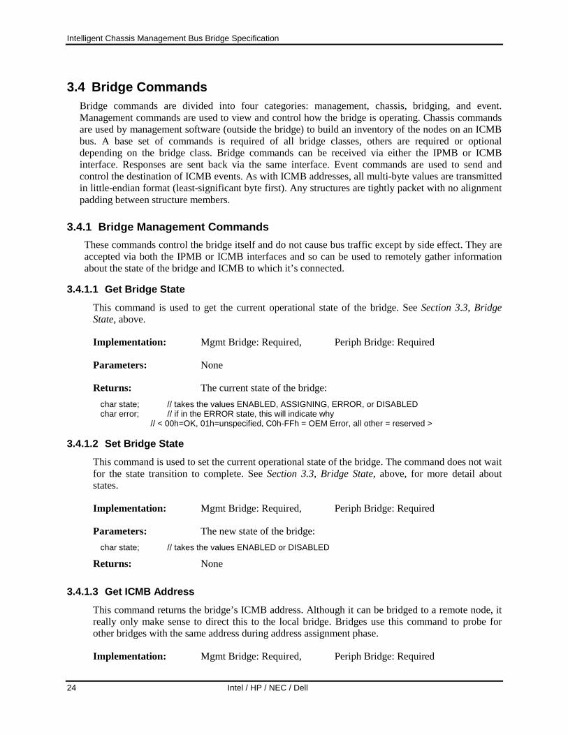
Intelligent Chassis Management Bus Bridge Specification
24 Intel / HP / NEC / Dell
3.4 Bridge Commands Bridge commands are divided into four categories: management, chassis, bridging, and event. Management commands are used to view and control how the bridge is operating. Chassis commands are used by management software (outside the bridge) to build an inventory of the nodes on an ICMB bus. A base set of commands is required of all bridge classes, others are required or optional depending on the bridge class. Bridge commands can be received via either the IPMB or ICMB interface. Responses are sent back via the same interface. Event commands are used to send and control the destination of ICMB events. As with ICMB addresses, all multi-byte values are transmitted in little-endian format (least-significant byte first). Any structures are tightly packet with no alignment padding between structure members.
3.4.1 Bridge Management Commands These commands control the bridge itself and do not cause bus traffic except by side effect. They are accepted via both the IPMB or ICMB interfaces and so can be used to remotely gather information about the state of the bridge and ICMB to which it’s connected.
3.4.1.1 Get Bridge State This command is used to get the current operational state of the bridge. See Section 3.3, Bridge State, above.
Implementation: Mgmt Bridge: Required, Periph Bridge: Required
Parameters: None
Returns: The current state of the bridge: char state; // takes the values ENABLED, ASSIGNING, ERROR, or DISABLED char error; // if in the ERROR state, this will indicate why
// < 00h=OK, 01h=unspecified, C0h-FFh = OEM Error, all other = reserved >
3.4.1.2 Set Bridge State This command is used to set the current operational state of the bridge. The command does not wait for the state transition to complete. See Section 3.3, Bridge State, above, for more detail about states.
Implementation: Mgmt Bridge: Required, Periph Bridge: Required
Parameters: The new state of the bridge: char state; // takes the values ENABLED or DISABLED
Returns: None 3.4.1.3 Get ICMB Address
This command returns the bridge’s ICMB address. Although it can be bridged to a remote node, it really only make sense to direct this to the local bridge. Bridges use this command to probe for other bridges with the same address during address assignment phase.
Implementation: Mgmt Bridge: Required, Periph Bridge: Required

Intelligent Chassis Management Bus Bridge Specification
Intel / HP / NEC / Dell 25
Parameters: None
Returns: The bridge’s ICMB address: unsigned short address;
3.4.1.4 Set ICMB Address This command sets the bridge’s ICMB address. Although it can be bridged to a remote node, it really only make sense to direct this to the local bridge.
Implementation: Mgmt Bridge: Required, Periph Bridge: Optional
Parameters: The bridge’s ICMB address: unsigned short address;
Returns: None.
3.4.1.5 Get Bridge Statistics This command is used to get the bridge’s ICMB and datalink statistics. This includes counts of total traffic in both directions as well as counts of the various types of errors that are detected. Counts include both broadcast and directed messages.
Implementation: Mgmt Bridge: Required, Periph Bridge: Optional
Parameters: Set of statistics to retrieve. char statSelector; // 0 = get ICMBstats0, 1 = get ICMBstats1. C0h-FFh = OEM. All other = reserved.
Returns: The bridge statistics: char statSelector; // Indicates which set of statistics is being returned.
// 0 = get ICMBstats0, 1 = get ICMBstats1. C0h-FFh = OEM. All other = reserved. struct ICMBstats0 { // returned if statSelector = 0 // bridge statistics: (counts are 1 based)
unsigned short runtCmd; // too short command from ICMB unsigned short badCommand; // illegal commands from ICMB
unsigned short spuriousResp; // number of spurious (unrequested) ICMB responses } structICMBstats1 { // returned if statSelector = 1 // datalink statistics:
unsigned short sent; // packets sent unsigned short received; // packets received unsigned short otherAddr; // packets to a different address unsigned short runtPkt; // too short packets unsigned short badChecksum; // packets with bad checksum unsigned short unkType; // packets with unknown type unsigned short notStart; // first character was not start char. unsigned short restart; // received start while receiving unsigned short arbWins; // won arbitrations unsigned short arbLosses; // lost arbitrations
}

Intelligent Chassis Management Bus Bridge Specification
26 Intel / HP / NEC / Dell
3.4.1.6 Clear Bridge Statistics
This command clears all bridge statistics returned by the GetBridgeStatistics command to 0.
Implementation: Mgmt Bridge: Required, Periph Bridge: Optional
Parameters: None.
Returns: None.
3.4.1.7 Get ICMB Capabilities This command returns the version number and revision level of the ICMB specification to which the bridge conforms. It also returns a bit mask indicating bridge feature. If a given feature is indicated as supported, then the bridge must support all required commands associated with that feature. Though listed as optional, this command is recommended for all new implementations.
Implementation: Mgmt Bridge: Optional, Periph Bridge: Optional
Parameters: None.
Returns: Version and feature bit mask
unsigned char ICMBversion; // spec version level, high/low nibbles = major/minor version
unsigned char ICMBrevision; // spec revision level, high/low nibbles = major/minor revision
unsigned char featureSupport; // bit mask of supported optional features
// bit 0 - Connector ID support // bit 1 - Management Bridge support. Bridge supports required
commands and mandatory functions for a management bridge.
// bit 2 - Peripheral Bridge support. Bridge supports required commands and mandatory functions for a peripheral bridge.
// bit 3 - Group Chassis Control support. Bridge and Chassis Device support required commands and mandatory functions for Group Chassis Control.
3.4.1.8 Set Bridge Proxy Address This command sets the remote chassis address, remote IPMB address, IPMB network function and LUN to use when IPMB commands are sent to the Bridge Proxy Device (LUN 1 of the Bridge Device). An IPMB request sent to the Bridge Proxy Device will be bridged to the IPMB address on the remote chassis specified by this command. The bridged request will be constructed using the network function and LUN specified here. This information does not expire and will stay in effect until changed or the bridge is disabled.

Intelligent Chassis Management Bus Bridge Specification
Intel / HP / NEC / Dell 27
To proxy a request to a device on a remote IPMB, first configure the destination address and LUN information using the SetBridgeProxyAddress command. Next, send the command to the bridge’s LUN 01b that you want to have executed on the remote device. The bridge will take that command and create a corresponding ICMB BridgeRequest message using the pre-configured destination address and LUN.
For example, assume that the Bridge resides at slave address 28h and that you want to send a ‘Get Device ID’ command to LUN 00b of a remote controller at slave address 26h in a chassis at ICMB address 8123h. The SetBridgeProxyAddress command would be used to save the remote slave address (26h) and ICMB address (8123h). To send the Get Device ID command, you’d format the command as if you were delivering it directly to the remote controller on the IPMB, but instead of using the remote slave address and LUN, you send the Get Device ID command to LUN 01b of the bridge.
Later, when the response comes back it will look as if the local bridge had executed the command. The requester’s LUN, slave address, and the Seq field in the response will be those that were passed in the original request to the local bridge, but the completion code and data will have come from the response from the remote device. If there is a failure in the bridging process, the local bridge will return an unspecified error (FFh) completion code.
Implementation: Mgmt Bridge: Required, Periph Bridge: Optional
Parameters: The addressing parameters: unsigned short ICMBAddress; // remote chassis address. unsigned char IPMBAddress; // address of IPMB node on remote chassis. unsigned char LUN; // LUN for IPMB node on remote chassis.
Returns: None.
3.4.1.9 Get Bridge Proxy Address This command allows the present setting of the Bridge Proxy Address to be retrieved.
Implementation: Mgmt Bridge: Optional, Periph Bridge: Optional
Parameters: None.
Returns: The present addressing parameters. unsigned short ICMBAddress; // remote chassis address. 0000h if address was not set. unsigned char IPMBAddress; // address of IPMB node on remote chassis. FFh if address not set. unsigned char LUN; // LUN for remote IPMB node. 00h if LUN not set.
3.4.1.10 Get ICMB Connector Info This command returns information about the ICMB connectors for the chassis. It is mandatory for chassis that support the Connector ID signals, and optional, but recommend, for all others. Note that the numeric IDs for the ICMB connectors on the chassis do not need to be sequential, though sequential numbering from ‘1’ is highly recommended.

Intelligent Chassis Management Bus Bridge Specification
28 Intel / HP / NEC / Dell
Implementation: Mgmt Bridge: Optional*, Periph Bridge: Optional* * Required for chassis that implement the Connector ID signals
Parameters: Numeric ID for ICMB connector to get information for. 00h to get ‘global’ information only.
unsigned char numericID; // Numeric ID for the connector. 00h = get flags and connector count information only.
Returns: Information about the ICMB connectors. unsigned char flags; // bitfield. 7:1 reserved. Return as 0 0 1 = Connector ID signals supported. unsigned char nConnectors; // The number of ICMB connectors unsigned char[] connectorType; // The connector type is encoded as: 00h = no connector at this numeric ID (also returned for if the
numericID parameter in the request was 00h) 01h = Type A connector 02h = Type B connector 03h = SSI Distributed Power Bay Connector (e.g. Foxconn
95077 Power Bay Header) all other = reserved unsigned char typeLength; // type/length byte per IPMI v1.0 specification. This byte specifies both
the encoding of the Connector ID string and the number of bytes in the string. 00h if no connector for given numericID, or if numericID in request was 00h.
unsigned char[ ] IDString; // Connector ID string bytes. This is a variable number of bytes. If the type/Length field is 00h, this field will be absent and the typeLength field will be the last field in the response. If the connectorType is 00h, this field should be ignored if present.
Command-specific completion codes: 81h // Illegal Connector ID. Indicates that the connector ID parameter is
out-of-range.
3.4.1.11 Get ICMB Connection ID This command directs the responder to return the ID of the connector that had its Connector ID signals asserted while the GetICMBConnection ID request was being received, if any. This is used to find out which connector on the responder is directly connected to the requester, if any. It is possible that a GetICMBConnectionID request could be received from another node before the corresponding GetICMBConnectionID response is sent. Therefore, the captured Connector ID state must be returned on a per-requester basis in order to ensure that each requester gets the captured state that was in effect while it was transmitting the GetICMBConnectionID request. Refer to Section 4.4, Connector ID Signal Generation, and Section 4.7, ICMB Cabling Topology Determination, for more information on the Connector ID signal and operation of the GetICMBConnectionID and SendICMBConnectionID commands.
Implementation: Mgmt Bridge: Optional*, Periph Bridge: Optional* * Required if chassis implements Connector ID signals
Parameters: None.
Returns: The requested connector ID information, or 00h value for the numeric ID and an empty ID string if no direct connections are found.

Intelligent Chassis Management Bus Bridge Specification
Intel / HP / NEC / Dell 29
unsigned char numericID; // Numeric ID for the connector. 00h = direct connection not found. unsigned char typeLength; // type/length byte per IPMI v1.0 specification. This byte specifies both
the encoding of the Connector ID string and the number of bytes in the string. 00h if direct connection not found, or if the chassis only provides a numeric ID for the connector.
unsigned char[ ] IDString; // Connector ID string bytes. This is a variable number of bytes. If the type/Length field is 00h, this field will be absent from the response.
3.4.1.12 Send ICMB Connection ID
This command helps management applications determine the cabling topology by directing a node to send a GetICMBConnectionID command on behalf of the requester. The need for and use of this command is discussed below. Support for executing this command from the IPMB is not required. That is, system software that wants to generate a GetICMBConnectionID command to a bridge on the ICMB should bridge that request, instead of using a SendICMBConnectionID command. Refer to Section 4.4, Connector ID Signal Generation, and Section 4.7, ICMB Cabling Topology Determination, for more information on the Connector ID signal and operation of the GetICMBConnectionID and SendICMBConnectionID commands.
Implementation: Mgmt Bridge: Optional*, Periph Bridge: Optional* * Required if chassis implements Connector ID signals
Parameters: unsigned short ICMBAddress; // remote chassis address. 0000h if address was not set.
Returns: The requested connector ID information, or 00h value for the numeric ID and an empty ID string if no direct connections are found.
unsigned char rCompletion; // Completion code returned by the forwarded GetICMBConnectionID command. If 00h (normal completion) the following parameters will be the response data from the GetICMBConnectionID command.
unsigned char numericID; // Numeric ID for the connector. 00h = direct connection not found. unsigned char typeLength; // type/length byte per IPMI v1.0 specification. This byte specifies both
the encoding of the Connector ID string and the number of bytes in the string. 00h if direct connection not found, or if the chassis only provides a numeric ID for the connector.
unsigned char[ ] IDString; // Connector ID string bytes. This is a variable number of bytes. If the type/Length field is 00h, this field will be absent from the response.
3.4.2 Bridge Chassis Commands Bridge Chassis commands are used by management software to build an inventory of the nodes on the ICMB and determine what kind of and which chassis they are. The process involves management software first sending a PrepareForDiscovery command on the IPMB, which in turn causes the local bridge to broadcast a PrepareForDiscovery command on the ICMB. Management software then issues GetAddresses commands to collect the addresses for a set of nodes. The GetAddresses command causes the local bridge to broadcast a GetICMBAddress command on the ICMB, which in turn causes the undiscovered nodes to return their addresses. A set of these addresses is returned in the IPMB response to the GetAddresses command. Management software then sends a SetDiscovered message to each node that it received an address for. The SetDiscovered message stops a node from responding to subsequent GetICMBAddress commands from that sender. The process stops once no more addresses are received in response to the GetAddresses command. Section 2.1.8, ICMB Population Discovery, discusses this in more detail.

Intelligent Chassis Management Bus Bridge Specification
30 Intel / HP / NEC / Dell
3.4.2.1 Prepare For Discovery This command is sent by management software to its local bridge to start the discovery process. The bridge will broadcast a PrepareForDiscovery message to all the other bridges on the ICMB. When a remote bridge receives this command from the ICMB, it clears its internal Discovered state (with respect to the sender). Remote bridges do not generate a response to this message. The local bridge generates the local IPMB response immediately after sending the command over the ICMB.
Implementation: Mgmt Bridge: Required, Periph Bridge: Required
Parameters: None
Returns: None.
3.4.2.2 Get Addresses Receiving this command via the IPMB interface causes a bridge to broadcast a GetICMBAddress message over the ICMB. A remote bridge receiving the broadcast command will respond with its ICMB address. The sending bridge will wait for a predetermined time and/or until the maximum number of addresses (8) have been accumulated. Then it responds to the local requester with the list of responding bridges. All further responses received by the bridge are ignored and the list sent to the requester is not remembered after the response to the GetAddresses command is made. The GetAddresses command is intended for execution from the IPMB and is not supported from the ICMB.
Implementation: Mgmt Bridge: Required, Periph Bridge: Required
Parameters: None
Returns: The list of addresses: unsigned short addresses[]; // Maximum length is 8 addresses

Intelligent Chassis Management Bus Bridge Specification
Intel / HP / NEC / Dell 31
3.4.2.3 Set Discovered This command is used to cause a bridge to not respond to any subsequent GetICMBAddress commands from the requesting bridge until it receives a PrepareForDiscovery command from that same bridge. Because this command is unicast, the local bridge device does not need to proxy it, as is done with the PrepareForDiscovery and GetAddresses commands. Instead, the requester delivers the SetDiscovered command to the remote bridge by using bridging to deliver it to the ICMB through the local bridge.
No bridging commands are accepted by a bridge after initialization (transition to Enabled state) until it has received at least one SetDiscovered command. This is to avoid potential problems due to a duplicate address collision.
Implementation: Mgmt Bridge: Required, Periph Bridge: Required
Parameters: None
Returns: None.
3.4.2.4 Get Chassis Device ID The IPMB address of the device implementing the chassis functions is returned by this command. This is the mechanism by which an external management agent can discover the chassis type, serial number, etc. Once that agent has the chassis device ID, it can issue IPMB commands to that device to continue the discovery process at the chassis level.
Implementation: Mgmt Bridge: Required, Periph Bridge: Required
Parameters: None
Returns: The chassis device ID for this chassis: char chassisDevId;
3.4.2.5 Set Chassis Device ID The IPMB address of the device implementing the chassis functions is set with this command so it can be made available to external chassis/management agents. Although no checks are made, this command should be sent to the bridge before its state is set to Enabled.
Implementation: Mgmt Bridge: Required, Periph Bridge: Required
Parameters: The chassis device ID for this chassis: char chassisDevId; bits 7:1 = address, 0 = reserved, write as 0b
Returns: None.

Intelligent Chassis Management Bus Bridge Specification
32 Intel / HP / NEC / Dell
3.4.3 Bridging Commands There are two bridging commands. They implement the main function of the bridge, which is to send IPMB commands to bridges and nodes on remote chassis for execution and return the results the local requester.
The commands differ with respect to response behavior. The Bridge Request command implies that the requester expects a response to its request from the remote node. The requester’s bridge will withhold a response until a response returns via the ICMB. The Bridge Message command, on the other hand, implies that the requester does not expect a reply from the remote node and so the requester’s bridge responds immediately. The Bridge Message command allows a requester to broadcast messages to other chassis. Due to the one-to-one nature of IPMB requests and responses, the Bridge Request command cannot be used for this purpose.
3.4.3.1 Bridge Request This command behaves differently, and accepts different parameters, depending on whether it is received via the IPMB or ICMB.
If it is received from the IPMB, the bridge will extract the remote bridge address and the command to be sent to that bridge from the command parameters and construct an ICMB message from them, including the remaining data portion of the IPMB message as data for the extracted command. The local bridge will then generate a sequence number to put in the ICMB message it constructs and remember that number, associating it with information from the original IPMB request so that it can generate a response to the requester from the ICMB response.
If a bridge command is received via the ICMB, the bridge will extract the IPMB slave address of the intended responder and construct an IPMB request to send to that address. The bridge will generate a sequence number to put in the IPMB request it constructs and remember that number, associating it with information from the original ICMB message so that it can generate a response to the requesting bridge from the IPMB response.
Implementation: Mgmt Bridge: Required, Periph Bridge: Required
Parameters: See Section 3.8, Message Delivery, for details.
Returns: See Section 3.8, Message Delivery, for details.
3.4.3.2 Bridge Message This command, when received from the IPMB, causes a bridge to construct and send an ICMB message as above, but no association is built and remembered. The bridge immediately generates a response to the command.
If received from the ICMB, a bridge will process as above, but no ICMB response will be generated. The IPMB response will be dropped.
Implementation: Mgmt Bridge: Required, Periph Bridge: Required

Intelligent Chassis Management Bus Bridge Specification
Intel / HP / NEC / Dell 33
Parameters: See Section 3.8, Message Delivery, for details.
Returns: See Section 3.8, Message Delivery, for details.
3.4.3.3 Device Bridge Request This command is only accepted from the ICMB. It is used to deliver a command to a selected device functionality using a 7-bit Device Selector value instead of an IPMB slave address. The bridge will generate an IPMB message to the selected Device functionality, but no association is built and remembered, and no ICMB response will be generated. The IPMB response will be dropped.
Implementation: Mgmt Bridge: Optional (but recommended), Periph Bridge: Optional (but recommended)
Parameters: See Section 3.8, Message Delivery, and 3.8.4, IPMI to Remote Device Messaging using DeviceBridgeRequest, for details.
Returns: See Section 3.8, Message Delivery, and 3.8.4, IPMI to Remote Device Messaging using DeviceBridgeRequest, for details.
Table 3-2, Device Selector Values
Code Name Description 7Eh Chassis Device Selector for the Chassis Device functionality in the chassis. This is typically the same
functionality that is identified by the GetChassisDeviceID command. all other
reserved reserved
3.4.4 Event Commands ICMB events are unacknowledged messages sent on the ICMB by a bridge on behalf of a node on its IPMB. The may be unicast or broadcast. This is the mechanism by which a chassis may get the attention of the system management software when an event-causing condition occurs, reducing failure-detection latency. Delivery is not guaranteed. The bridge will periodically resend the event a small number of times. It is expected that system management software will want to poll periodically to discover events that might have been missed.
An event-generating chassis always has the option of bridging an IPMB event request to a specific management chassis. This has the benefit of allowing the requester to format the event request to its specifications. However, since bridged IPMB messages cannot be broadcast over the ICMB, the requester must send to a specific chassis. If the event request is bridged, the normal IPMB bridging behavior will occur, i.e. the event response will be generated on the remote chassis and bridged back to the originating chassis.

Intelligent Chassis Management Bus Bridge Specification
34 Intel / HP / NEC / Dell
3.4.4.1 Send ICMB Event Message This command sends an ICMB event message to the currently set ICMB event destination. Since the ICMB message is not acknowledged, the bridge provides the response to the requesting node. Only a single byte event code parameter is allowed as input parameter. An ICMB event is only meant to indicate need of service, not to provide significant detail on the particular triggering condition.
Implementation: Mgmt Bridge: Required, Periph Bridge: Required
Parameters: Type of event: char eventCode; // values = See the following table, and Chapter 5. Bridge Command Summary
Returns: None.
Table 3-3, ICMB Event Codes
Code Name Description 0 OnLine This event is broadcast whenever a bridge is waiting to be discovered. This will typically
occur when the bridge is first initialized when chassis standby power comes up. The bridge will also generate this event whenever it is disabled then re-enabled.
1 Attention This event is broadcast whenever a bridge has a new internal event condition that should receive the attention of System Management Software. This occurs when: - the SEL is changed (new entry added, or SEL cleared) - when any transition between system powered up (ACPI S0-S3) and powered down
(ACPI S5/S4) occurs. 2 Discovery
Start System Management Software issues this event to notify management software in other systems that it is about to perform the discovery process. This event should be sent at least 3 times to help ensure that other systems receive it. The event also determines whether a system will interrupt a discovery process that is already in progress from another system. The bridge address determines whether a system will cease discovery upon receiving a Discovery Start event. Software will cease discovery if it receives a Discovery Start event from a bridge that has a higher address than the system’s local bridge. However, if a system receiving the event already has a discovery in progress and finds that its local bridge has the greater address, it will send a Discovery Start event of its own. It is recommended that a system restarts its discovery process if it sends a Discovery Start as the result of receiving a Discovery Start from another system. The reason for this is that software delays may allow the other system may have gotten fairly far into the discovery process before it gets stopped. The system that is performing discovery must issue the Discovery Start event at least once every 5 seconds until it completes the discovery process. (If the discovery takes less than 5 seconds, then the initial Discovery Start messages are sufficient).
3 Discovery End
System Management Software issues this event to notify management software in other systems that his has completed the discovery process, or aborted the discovery process for a reason other than receiving a Discovery Start event from another system. The reason a Discovery Start event is not allowed to trigger a Discovery End is to ensure the Discovery End event only indicates the completion or termination of the discovery process, not the interruption and ‘take over’ of the discovery process by another system. A system that has received a Discovery Start event can assume that the discovery process has been terminated if it has been more than 15 seconds since it received the last Discovery Start event.

Intelligent Chassis Management Bus Bridge Specification
Intel / HP / NEC / Dell 35
3.4.4.2 Set Event Destination This command sets the ICMB address to which ICMB events are sent. The address can be a specific ICMB bridge or the ICMB broadcast address. As of this writing, the main use for this message is to support the test and development of bridge devices.
The bridge shall default to using the broadcast address until overridden with this command. The address is only preserved while the bridge is powered via standby or main power.
Implementation: Mgmt Bridge: Required, Periph Bridge: Required
Parameters: The destination address. unsigned short ICMBAddress; // values = a valid ICMB address
Returns: None.
3.4.4.3 Set Event Reception State This command is used to control whether received ICMB events will cause the bridge to generate a bridge event on its local IPMB and if so, to what node.
Implementation: Mgmt Bridge: Required, Periph Bridge: Required
Parameters: The reception state, IPMB slave address, and LUN. char state; // values = 1 - enable bridge events, or 0 - disable bridge events char eventSA; // IPMB slave address for bridge event receiver char LUN; // logical device on bridge event receiver
Returns: None.
3.4.4.4 Get Bridge Event Count The bridge counts all events sent through it, modulo 256. Making this count available allows system management software to easily determine whether any events have occurred since the last time it checked. The count rolls over to 00h after it hits FFh.
Implementation: Mgmt Bridge: Required, Periph Bridge: Required
Parameters: None.
Returns: The current event count. unsigned char count;

Intelligent Chassis Management Bus Bridge Specification
36 Intel / HP / NEC / Dell
3.5 Chassis Device Commands These commands are used to access the Chassis Device functionality in the chassis. Chassis Device commands are specified in the IPMI specification. However, as of this writing some of these commands have not been incorporated into the IPMI specification. These are described below. The chassis device commands are implemented by the device identified by the GetChassisDeviceID bridge command described earlier.
3.5.1 Get Chassis Capabilities The GetChassisCapabilities command returns information about which main chassis management functions are present on the IPMB (or virtual IPMB) and what addresses are used to access those functions.
Implementation: Mgmt Chassis Device: Required, Periph Chassis Device: Required
Parameters: None.
Returns: Capabilities flags and address information for the devices implementing the base chassis management functions.
unsigned char CapsFlags; // Capabilities Flags bit 0 - Provides intrusion bit 1 - Provides Secure Mode (this indicates that the chassis
has capabilities to lock out external power control and reset button interfaces and/or detect tampering with those interfaces)
bit 2 - Provides Diagnostic Interrupt (FP NMI) (this indicates that the chassis supports a push-button or panel interface that allows a user to trigger a diagnostic ‘dump’ interrupt).
bit 3 - Provides Interlock (this indicates that the chassis supports an automatic interlock that shuts off system power if a particular chassis panel is removed or service door is opened.)
unsigned char ChassisFRUAddr; // Chassis FRU Info Device Address. Note: all IPMB addresses
used in this command are have the 7-bit slave address as the most-significant 7-bits and the least significant bit set to 0. 00h will be returned if the address is unspecified or unassigned.
unsigned char ChassisSDRAddr; // Chassis SDR Device Address unsigned char ChassisSELAddr; // Chassis SEL Device Address unsigned char ChassisSMAddr; // Chassis System Management Device Address unsigned char ChassisBridgeAddr // Chassis Bridge Device Address. Reports location of the ICMB
bridge function. If this field is not provided, the address is assumed to be the BMC address (20h). Implementing this field is required when the Get Chassis Capabilities command is implemented by a BMC, and whenever the Chassis Bridge function is implemented at an address other than 20h.
There is no one required mechanism for getting this information set into the Chassis Device. The Chassis Device function in a peripheral chassis may be hardcoded with this information. A system that implements the ICMB as an add-on bridge to a BMC will typically be able to have the well known address for the BMC (20h) hardcoded as the return for the Chassis SDR, SEL, and SM Device

Intelligent Chassis Management Bus Bridge Specification
Intel / HP / NEC / Dell 37
addresses, while the Chassis FRU Info Device address could be set with the chassis devices own address.
The Capabilities Flags are more problematic for an add-on bridge that may be designed for multiple systems. A mechanism is required for configuring these flags for the system. There are several approaches.
The recommended approach is to implement the SetChassisCapabilities command and provide non-volatile storage for the capabilities settings. This would enable a standardized utility, or future versions of the IPMI initialization agent, to configure this information.
Another approach is to implement the configuration as part of the Internal Use area of a FRU Device associated with the chassis device, and use the FRU access commands to allow the information to be configured.
Yet another approach is to implement a proprietary configuration utility for the controller that works by sending proprietary IPMB commands via the IPMI system interface, or even via the ICMB.
3.5.2 Get Chassis Status The GetChassisStatus command is used to return ‘high-level’ information about the overall health status and present state of the chassis.
Implementation: Mgmt Chassis Device: Required, Periph Chassis Device: Required
Parameters: None.
Returns: Status flags indicating the overall health status and present state of the chassis. This information often corresponds to the setting of individual fault lights on the chassis. Unless otherwise specified, ‘1’ indicates the active state of the flag and ‘0’ the inactive state. ‘0’ is also returned for any unsupported status flags.
unsigned char CurrentPowerState; // Power State Flags bit 0 - Power is on bit 1 - Power overload (chassis is presently shut down because
of an over-current condition) bit 2 - Interlock (chassis is presently shut down because a
chassis panel interlock switch is active). bit 3 - Power Fault (a power fault condition has been detected
and is presently active) bit 4 - Power Control Fault (a power control fault condition has
been detected and is presently active. A power control fault is the condition where the power state does not match the requested state from the power control logic. For example, the control logic is requesting power to be ON but power is remaining OFF.)
bit 6:5 - Power restore policy. (Indicates the active power restore policy for the chassis. The power control policy indicates the behavior of the system following the application or restoration of AC power) 00b = chassis stays powered off after AC returns 01b = after AC returns, the chassis power is restored to
the state that was in effect when AC was lost
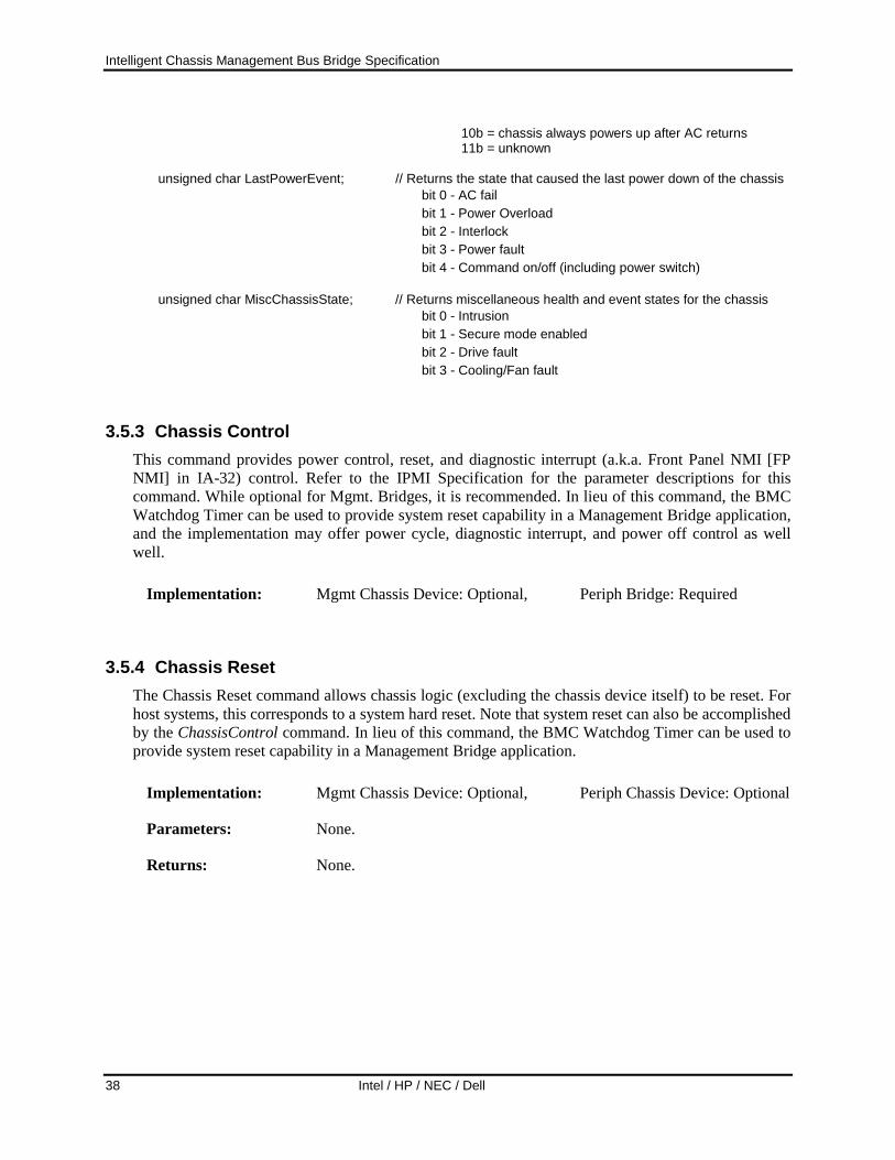
Intelligent Chassis Management Bus Bridge Specification
38 Intel / HP / NEC / Dell
10b = chassis always powers up after AC returns 11b = unknown
unsigned char LastPowerEvent; // Returns the state that caused the last power down of the chassis
bit 0 - AC fail bit 1 - Power Overload bit 2 - Interlock bit 3 - Power fault bit 4 - Command on/off (including power switch)
unsigned char MiscChassisState; // Returns miscellaneous health and event states for the chassis
bit 0 - Intrusion bit 1 - Secure mode enabled bit 2 - Drive fault bit 3 - Cooling/Fan fault
3.5.3 Chassis Control This command provides power control, reset, and diagnostic interrupt (a.k.a. Front Panel NMI [FP NMI] in IA-32) control. Refer to the IPMI Specification for the parameter descriptions for this command. While optional for Mgmt. Bridges, it is recommended. In lieu of this command, the BMC Watchdog Timer can be used to provide system reset capability in a Management Bridge application, and the implementation may offer power cycle, diagnostic interrupt, and power off control as well well.
Implementation: Mgmt Chassis Device: Optional, Periph Bridge: Required
3.5.4 Chassis Reset The Chassis Reset command allows chassis logic (excluding the chassis device itself) to be reset. For host systems, this corresponds to a system hard reset. Note that system reset can also be accomplished by the ChassisControl command. In lieu of this command, the BMC Watchdog Timer can be used to provide system reset capability in a Management Bridge application.
Implementation: Mgmt Chassis Device: Optional, Periph Chassis Device: Optional
Parameters: None.
Returns: None.

Intelligent Chassis Management Bus Bridge Specification
Intel / HP / NEC / Dell 39
3.5.5 Chassis Identify This command causes the chassis to physically identify itself by blinking user-visible lights or emitting beeps via a speaker, LCD panel, etc. The ChassisIdentify command automatically times out and deasserts the indication after 15 seconds -0/+20%. Software must periodically resend the command to keep the identify condition asserted.
Implementation: Mgmt Chassis Device: Optional, Periph Chassis Device: Optional
Parameters: None.
Returns: None.
3.5.6 Group Chassis Control This command provides a mechanism to broadcast a control request to multiple chassis.
Implementation: Mgmt Chassis Device: Optional, but recommended for new implementations. Periph Chassis Device: Optional, but recommended for new implementations.
Parameters: The requested control operation, flags indicating whether the control operation should be ‘forced’ or ‘requested’, and whether the operation should occur immediately, or after a pre-configured delay (See Set Group Control Enables command), and which chassis group(s) and group member(s) the operation is targeted to.
unsigned char Control // Selects the desired operation and whether the operation should be delayed // or immediate, and whether it should be requested or forced.

Intelligent Chassis Management Bus Bridge Specification
40 Intel / HP / NEC / Dell
bit 3:0 - operation 0h = power down. Force chassis/system into soft off
(S4/S5). Note this command does not initiate a graceful shutdown of the system prior to powering down.
1h = power up. 2h = power cycle (optional). This command provides a
power off interval of at least one (1) second. 3h = hard reset. Note: Some systems may accept this
operation even if the system is in a state (e.g. powered down) where resets are unavailable.)
4h = pulse Diagnostic Interrupt (optional). Pulses a version of a diagnostic interrupt that goes directly to the processor(s). This is typically used to cause the operating system to do a diagnostic dump (OS dependent). The interrupt is commonly an NMI on IA-32 system and an INIT on Intel® Itanium™ processor based systems.
5h = (optional) Initiate a soft-shutdown of OS via ACPI by emulating a fatal overtemperature.
bit 5:4 - operation delay control 00b = operation occurs immediately 01b = operation occurs after pre-configured delay. 10b = cancel operation. This will cause a pending
delayed/requested operation to be canceled, provided the command is received at least two (2) seconds before the delay times out or before the requested control state is match across the enabled groups and group members. Forced operations can’t be canceled.
bit 6 - reserved bit 7 - Request/Force 0b = request operation. Operation will occur once the
chassis that receives this command has received the same operation request for all chassis group and member IDs that have been enabled for group control. Note that a given operation can be configured to be enabled to be taken if only a single member requests it within a group.
This can be used to enable a system to be configured so that it can be powered up on any request, but powered down only if all member request the power down state.
1b = force control operation. Operation will be initiated independent of the control request state for the other chassis group and member IDs that have been enabled for group control. Note that the group ID/member ID in the request must still match one of the enabled group ID/member ID settings in order for the request to be executed on the target chassis.
// There are four group ID/member ID pairs that are supported with the following parameters. // Thus, a single GroupChassisControl command can be targeted to up to four different chassis groups // simultaneously.

Intelligent Chassis Management Bus Bridge Specification
Intel / HP / NEC / Dell 41
unsigned char GroupID0 // 1-based. Indicates the ID of the group that the control operation is targeted to. 00h = unspecified 01h-FEh = group ID FFh = all groups unsigned char MemberID0 // 0-based. Indicates the ID of the group member that the control operation is // targeted to, and selects whether the member ID should be checked. bit 3:0 - member ID. ID of the requesting chassis within the
specified group. (value ignored if Group ID = 00h or FFh)
bit 4 - member ID check 0b = perform member ID check. 1b = skip member ID check. bit 7:5 - reserved unsigned char GroupID1 // 1-based. Indicates the ID of the group that the control operation is targeted to. 00h = unspecified 01h-FEh = group ID FFh = all groups unsigned char MemberID1 // 0-based. Indicates the ID of the group member that the control operation is // targeted to, and selects whether the member ID should be checked. bit 3:0 - member ID. ID of the requesting chassis within the
specified group. (value ignored if Group ID = 00h or FFh)
bit 4 - member ID check 0b = perform member ID check. 1b = skip member ID check. bit 7:5 - reserved unsigned char GroupID2 // 1-based. Indicates the ID of the group that the control operation is targeted to. 00h = unspecified 01h-FEh = group ID FFh = all groups unsigned char MemberID2 // 0-based. Indicates the ID of the group member that the control operation is // targeted to, and selects whether the member ID should be checked. bit 3:0 - member ID. ID of the requesting chassis within the
specified group. (value ignored if Group ID = 00h or FFh)
bit 4 - member ID check 0b = perform member ID check. 1b = skip member ID check. bit 7:5 - reserved unsigned char GroupID3 // 1-based. Indicates the ID of the group that the control operation is targeted to. 00h = unspecified 01h-FEh = group ID FFh = all groups unsigned char MemberID3 // 0-based. Indicates the ID of the group member that the control operation is // targeted to, and selects whether the member ID should be checked.
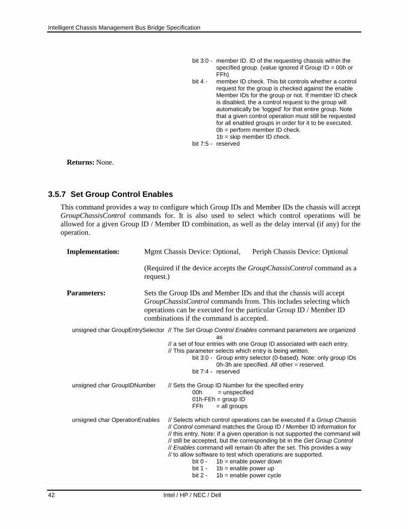
Intelligent Chassis Management Bus Bridge Specification
42 Intel / HP / NEC / Dell
bit 3:0 - member ID. ID of the requesting chassis within the specified group. (value ignored if Group ID = 00h or FFh)
bit 4 - member ID check. This bit controls whether a control request for the group is checked against the enable Member IDs for the group or not. If member ID check is disabled, the a control request to the group will automatically be ‘logged’ for that entire group. Note that a given control operation must still be requested for all enabled groups in order for it to be executed.
0b = perform member ID check. 1b = skip member ID check. bit 7:5 - reserved
Returns: None.
3.5.7 Set Group Control Enables This command provides a way to configure which Group IDs and Member IDs the chassis will accept GroupChassisControl commands for. It is also used to select which control operations will be allowed for a given Group ID / Member ID combination, as well as the delay interval (if any) for the operation.
Implementation: Mgmt Chassis Device: Optional, Periph Chassis Device: Optional
(Required if the device accepts the GroupChassisControl command as a request.)
Parameters: Sets the Group IDs and Member IDs and that the chassis will accept GroupChassisControl commands from. This includes selecting which operations can be executed for the particular Group ID / Member ID combinations if the command is accepted.
unsigned char GroupEntrySelector // The Set Group Control Enables command parameters are organized as
// a set of four entries with one Group ID associated with each entry. // This parameter selects which entry is being written. bit 3:0 - Group entry selector (0-based). Note: only group IDs
0h-3h are specified. All other = reserved. bit 7:4 - reserved unsigned char GroupIDNumber // Sets the Group ID Number for the specified entry 00h = unspecified 01h-FEh = group ID FFh = all groups unsigned char OperationEnables // Selects which control operations can be executed if a Group Chassis // Control command matches the Group ID / Member ID information for // this entry. Note: if a given operation is not supported the command will // still be accepted, but the corresponding bit in the Get Group Control
// Enables command will remain 0b after the set. This provides a way // to allow software to test which operations are supported.
bit 0 - 1b = enable power down bit 1 - 1b = enable power up bit 2 - 1b = enable power cycle
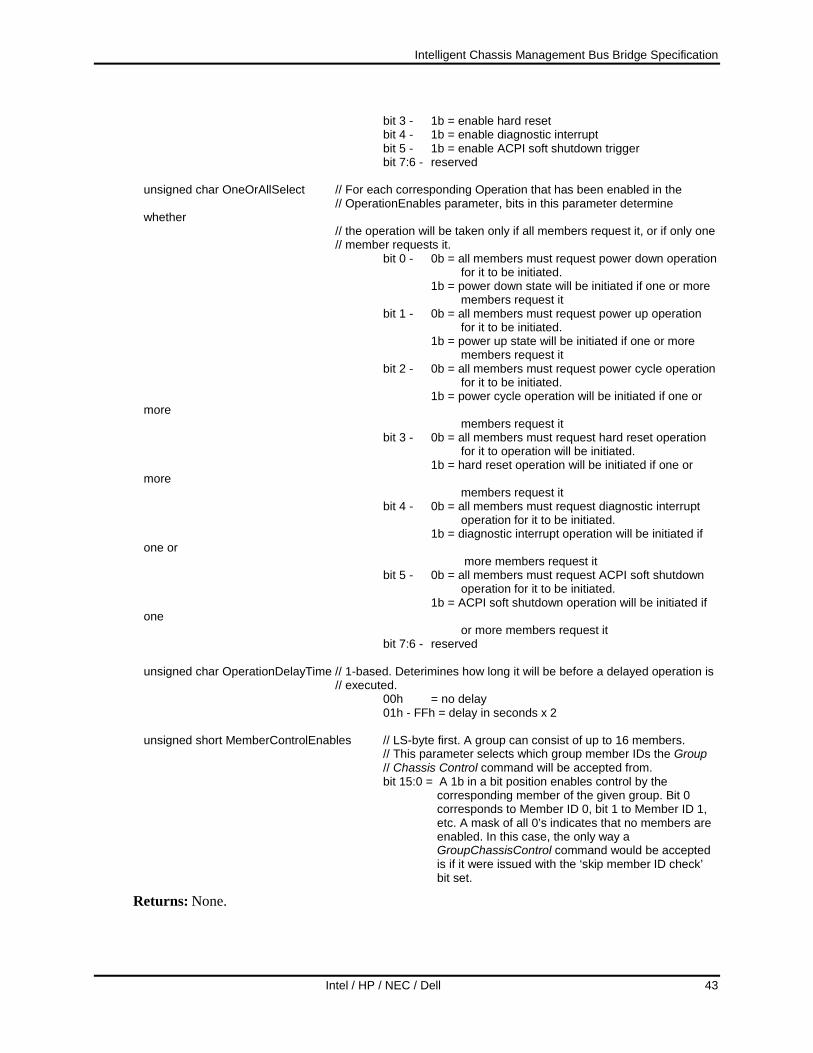
Intelligent Chassis Management Bus Bridge Specification
Intel / HP / NEC / Dell 43
bit 3 - 1b = enable hard reset bit 4 - 1b = enable diagnostic interrupt bit 5 - 1b = enable ACPI soft shutdown trigger bit 7:6 - reserved unsigned char OneOrAllSelect // For each corresponding Operation that has been enabled in the // OperationEnables parameter, bits in this parameter determine whether // the operation will be taken only if all members request it, or if only one // member requests it. bit 0 - 0b = all members must request power down operation
for it to be initiated. 1b = power down state will be initiated if one or more
members request it bit 1 - 0b = all members must request power up operation
for it to be initiated. 1b = power up state will be initiated if one or more
members request it bit 2 - 0b = all members must request power cycle operation
for it to be initiated. 1b = power cycle operation will be initiated if one or more
members request it bit 3 - 0b = all members must request hard reset operation
for it to operation will be initiated. 1b = hard reset operation will be initiated if one or more
members request it bit 4 - 0b = all members must request diagnostic interrupt
operation for it to be initiated. 1b = diagnostic interrupt operation will be initiated if one or
more members request it bit 5 - 0b = all members must request ACPI soft shutdown
operation for it to be initiated. 1b = ACPI soft shutdown operation will be initiated if one
or more members request it bit 7:6 - reserved unsigned char OperationDelayTime // 1-based. Deterimines how long it will be before a delayed operation is // executed. 00h = no delay 01h - FFh = delay in seconds x 2 unsigned short MemberControlEnables // LS-byte first. A group can consist of up to 16 members. // This parameter selects which group member IDs the Group // Chassis Control command will be accepted from.
bit 15:0 = A 1b in a bit position enables control by the corresponding member of the given group. Bit 0 corresponds to Member ID 0, bit 1 to Member ID 1, etc. A mask of all 0’s indicates that no members are enabled. In this case, the only way a GroupChassisControl command would be accepted is if it were issued with the ‘skip member ID check’ bit set.
Returns: None.
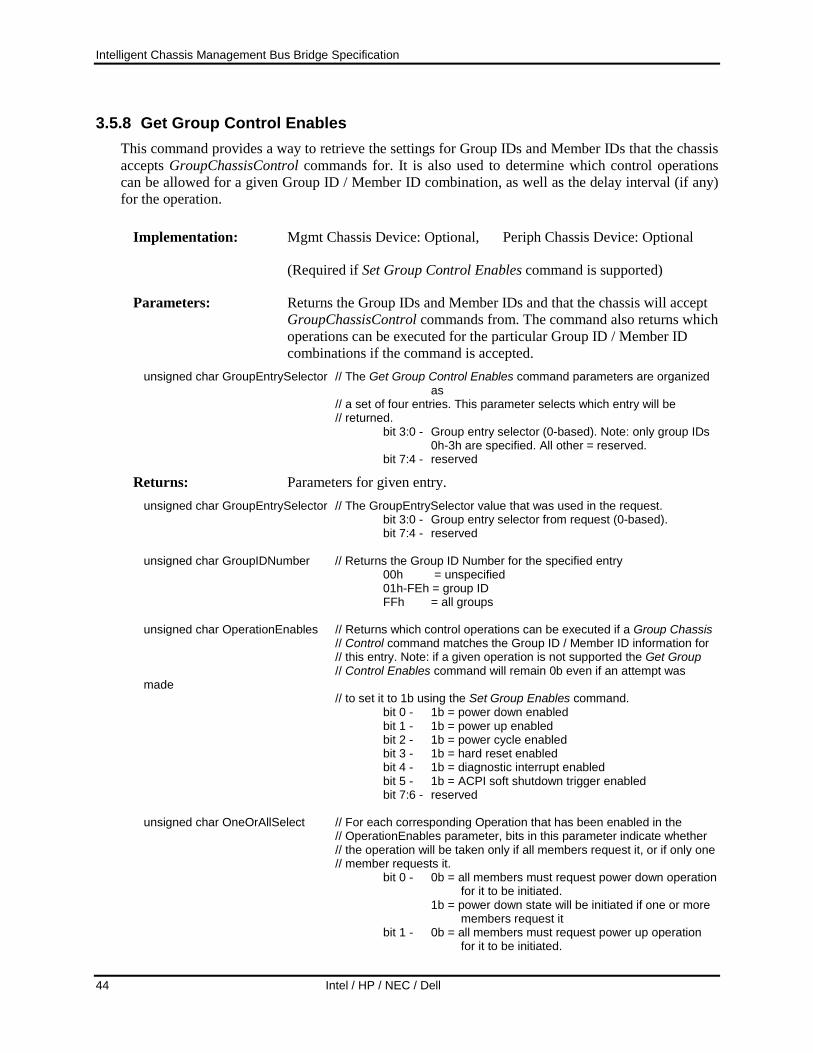
Intelligent Chassis Management Bus Bridge Specification
44 Intel / HP / NEC / Dell
3.5.8 Get Group Control Enables This command provides a way to retrieve the settings for Group IDs and Member IDs that the chassis accepts GroupChassisControl commands for. It is also used to determine which control operations can be allowed for a given Group ID / Member ID combination, as well as the delay interval (if any) for the operation.
Implementation: Mgmt Chassis Device: Optional, Periph Chassis Device: Optional
(Required if Set Group Control Enables command is supported)
Parameters: Returns the Group IDs and Member IDs and that the chassis will accept GroupChassisControl commands from. The command also returns which operations can be executed for the particular Group ID / Member ID combinations if the command is accepted.
unsigned char GroupEntrySelector // The Get Group Control Enables command parameters are organized as
// a set of four entries. This parameter selects which entry will be // returned. bit 3:0 - Group entry selector (0-based). Note: only group IDs
0h-3h are specified. All other = reserved. bit 7:4 - reserved
Returns: Parameters for given entry. unsigned char GroupEntrySelector // The GroupEntrySelector value that was used in the request. bit 3:0 - Group entry selector from request (0-based). bit 7:4 - reserved unsigned char GroupIDNumber // Returns the Group ID Number for the specified entry 00h = unspecified 01h-FEh = group ID FFh = all groups unsigned char OperationEnables // Returns which control operations can be executed if a Group Chassis // Control command matches the Group ID / Member ID information for // this entry. Note: if a given operation is not supported the Get Group // Control Enables command will remain 0b even if an attempt was made // to set it to 1b using the Set Group Enables command. bit 0 - 1b = power down enabled bit 1 - 1b = power up enabled bit 2 - 1b = power cycle enabled bit 3 - 1b = hard reset enabled bit 4 - 1b = diagnostic interrupt enabled bit 5 - 1b = ACPI soft shutdown trigger enabled bit 7:6 - reserved unsigned char OneOrAllSelect // For each corresponding Operation that has been enabled in the // OperationEnables parameter, bits in this parameter indicate whether // the operation will be taken only if all members request it, or if only one // member requests it. bit 0 - 0b = all members must request power down operation
for it to be initiated. 1b = power down state will be initiated if one or more
members request it bit 1 - 0b = all members must request power up operation
for it to be initiated.

Intelligent Chassis Management Bus Bridge Specification
Intel / HP / NEC / Dell 45
1b = power up state will be initiated if one or more members request it
bit 2 - 0b = all members must request power cycle operation for it to be initiated.
1b = power cycle operation will be initiated if one or more
members request it bit 3 - 0b = all members must request hard reset operation
for it to operation will be initiated. 1b = hard reset operation will be initiated if one or more
members request it bit 4 - 0b = all members must request diagnostic interrupt
operation for it to be initiated. 1b = diagnostic interrupt operation will be initiated if one or
more members request it bit 5 - 0b = all members must request ACPI soft shutdown
operation for it to be initiated. 1b = ACPI soft shutdown operation will be initiated if one
or more members request it bit 7:6 - reserved unsigned char OperationDelayTime // 1-based. Returns how long it will be before a delayed operation is // executed. 00h = no delay 01h - FFh = delay in seconds x 2 unsigned short MemberControlEnables // LS-byte first. A group can consist of up to 16 members. // This parameter returns which group member IDs the Group // Chassis Control command will be accepted from.
bit 15:0 = member control enables. A 1b in a bit position enables control by the corresponding member of the given group. Bit 0 corresponds to Member ID 0, bit 1 to Member ID 1, etc. A mask of all 0’s indicates that no members are enabled. In this case, the only way a GroupChassisControl command would be accepted is if it were issued with the ‘skip member ID check’ bit set.
3.5.9 Get Control Group Settings This command is used return the operation enables, operation delay times, and member ID enables for all four control groups simultaneously. It is intended to provide a more efficient way for software to retrieve this information instead of issuing multiple Get Group Control Enable commands. The command can be used with the Get Group Control Status command to enable software to understand the present state of operations and operation requests on the chassis.
Implementation: Mgmt Chassis Device: Optional, Periph Chassis Device: Optional
(Required if Set Group Control Enables command is supported)
Parameters: reserved. unsigned char reserved1 // Write as 00h 00h

Intelligent Chassis Management Bus Bridge Specification
46 Intel / HP / NEC / Dell
Returns: Operation enables, operation delay times, and member ID enables for all four Control Group entries.
unsigned char OperationEnables0 // Operation Enables for Group Entry 0 // Returns which control operations can be executed if a Group Chassis // Control command matches the Group ID / Member ID information for // this entry. Note: if a given operation is not supported the Get Group // Control Enables command will remain 0b even if an attempt was made // to set it to 1b using the Set Group Enables command. bit 0 - 1b = power down enabled bit 1 - 1b = power up enabled bit 2 - 1b = power cycle enabled bit 3 - 1b = hard reset enabled bit 4 - 1b = diagnostic interrupt enabled bit 5 - 1b = ACPI soft shutdown trigger enabled bit 7:6 - reserved unsigned char OperationDelayTime0 // Operation Delay Time for Group Entry 0 // 1-based. Returns how long it will be before a delayed operation is // executed. 00h = no delay 01h - FFh = delay in seconds x 2 unsigned short MemberControlEnables0 // Member Control Enables for Group Entry 0 // LS-byte first. A group can consist of up to 16 members. // This parameter selects which group member IDs the Group // Chassis Control command will be accepted from.
bit 15:0 = A 1b in a bit position enables control by the corresponding member of the given group. Bit 0 corresponds to Member ID 0, bit 1 to Member ID 1, etc. A mask of all 0’s indicates that no members are enabled. In this case, the only way a GroupChassisControl command would be accepted is if it were issued with the ‘skip member ID check’ bit set.
unsigned char OperationEnables1 // Operation Enables for Group Entry 1 unsigned char OperationDelayTime1 // Operation Delay Time for Group Entry 1 unsigned short MemberControlEnables1 // Member Control Enables for Group Entry 1 unsigned char OperationEnables2 // Operation Enables for Group Entry 1 unsigned char OperationDelayTime2 // Operation Delay Time for Group Entry 1 unsigned short MemberControlEnables2 // Member Control Enables for Group Entry 1 unsigned char OperationEnables3 // Operation Enables for Group Entry 1 unsigned char OperationDelayTime3 // Operation Delay Time for Group Entry 1 unsigned short MemberControlEnables3 // Member Control Enables for Group Entry 1

Intelligent Chassis Management Bus Bridge Specification
Intel / HP / NEC / Dell 47
3.5.10 Get Group Control Status This command is used to retrieve various statuses about Group Control on the given chassis. The command allows software to determine the present state of pending control operation requests so that it can determine whether other groups or group members have requested control operations. A ‘response selector’ is used to determine whether the status is looked up according by Group ID, Group Entry number, or operation. The information returned includes the setting of the operation enables, whether there are pending control operation requests from members of the given group, and what Group IDs presently have requests outstanding for a given operation.
Implementation: Mgmt Chassis Device: Optional, Periph Chassis Device: Optional
(Required if Set Group Control Enables command is supported)
Parameters: Response selector, used to return a response based on whether the response should be looked up based on Group ID, Group Entry number, or by Operation.
unsigned char ResponseSelector // Selects whether the response should be returned based on Group ID, Group // Entry number, or by Operation
bit 3:0 - response selector. 0h = by group. Looks up whether given Group ID matches
any of the enabled Group IDs and if so, return pending operation request status for that Group ID. Otherwise, returns command-specific completion code.
1h = by entry. Returns pending request data for given Group Entry number.
2h = by operation. Returns pending operation request status for given operation.
bit 7:4 - reserved
unsigned char SelectorValue // Parameter depends on value of the ResponseSelector // For response selector = “by group”: Group ID number. 00h = reserved // For response selector = “by entry”:
bit 3:0 -Group Entry number 0h = Entry 0 1h = Entry 1 2h = Entry 2 3h = Entry 3 all other = reserved
bit 7:4 - reserved
// For response selector = “by operation”: bit 3:0 - Operation 0h = power down 1h = power up 2h = power cycle 3h = hard reset 4h = Diagnostic Interrupt 5h = ACPI emulated soft-shutdown bit 7:4 - reserved
Returns: Status according to Response Selector
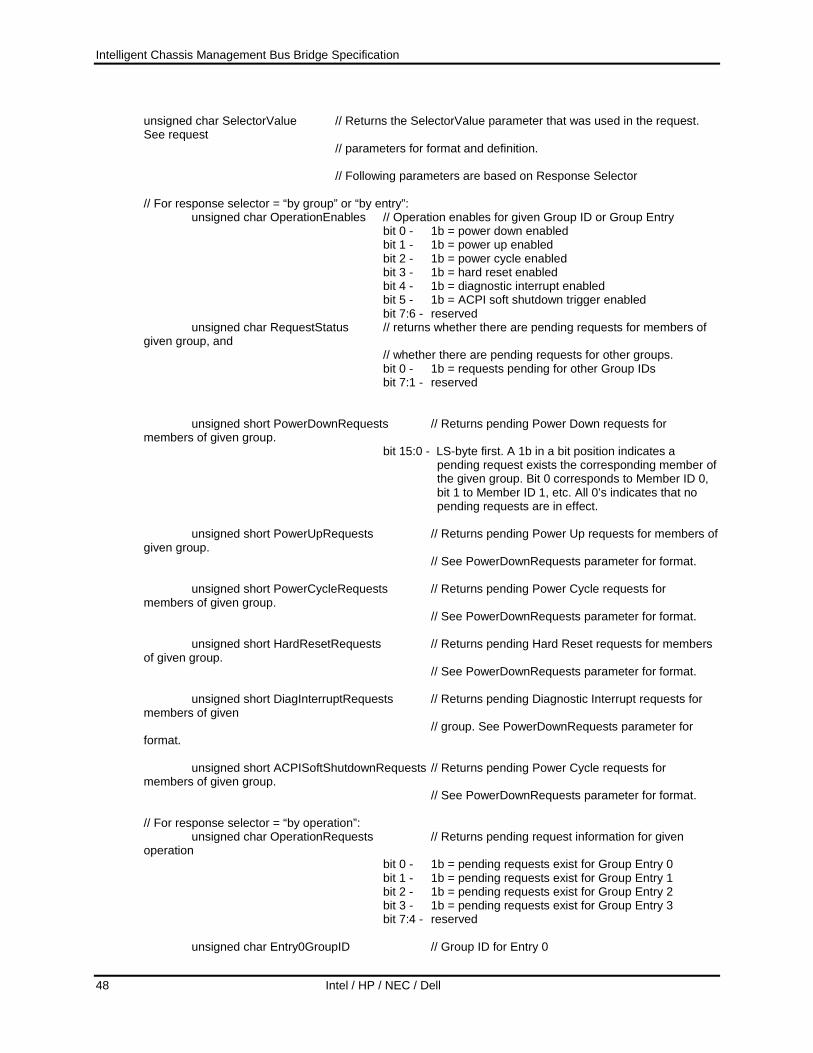
Intelligent Chassis Management Bus Bridge Specification
48 Intel / HP / NEC / Dell
unsigned char SelectorValue // Returns the SelectorValue parameter that was used in the request. See request // parameters for format and definition. // Following parameters are based on Response Selector // For response selector = “by group” or “by entry”: unsigned char OperationEnables // Operation enables for given Group ID or Group Entry bit 0 - 1b = power down enabled bit 1 - 1b = power up enabled bit 2 - 1b = power cycle enabled bit 3 - 1b = hard reset enabled bit 4 - 1b = diagnostic interrupt enabled bit 5 - 1b = ACPI soft shutdown trigger enabled bit 7:6 - reserved unsigned char RequestStatus // returns whether there are pending requests for members of given group, and // whether there are pending requests for other groups. bit 0 - 1b = requests pending for other Group IDs bit 7:1 - reserved unsigned short PowerDownRequests // Returns pending Power Down requests for members of given group.
bit 15:0 - LS-byte first. A 1b in a bit position indicates a pending request exists the corresponding member of the given group. Bit 0 corresponds to Member ID 0, bit 1 to Member ID 1, etc. All 0’s indicates that no pending requests are in effect.
unsigned short PowerUpRequests // Returns pending Power Up requests for members of given group. // See PowerDownRequests parameter for format. unsigned short PowerCycleRequests // Returns pending Power Cycle requests for members of given group. // See PowerDownRequests parameter for format. unsigned short HardResetRequests // Returns pending Hard Reset requests for members of given group. // See PowerDownRequests parameter for format. unsigned short DiagInterruptRequests // Returns pending Diagnostic Interrupt requests for members of given // group. See PowerDownRequests parameter for format. unsigned short ACPISoftShutdownRequests // Returns pending Power Cycle requests for members of given group. // See PowerDownRequests parameter for format. // For response selector = “by operation”: unsigned char OperationRequests // Returns pending request information for given operation
bit 0 - 1b = pending requests exist for Group Entry 0 bit 1 - 1b = pending requests exist for Group Entry 1 bit 2 - 1b = pending requests exist for Group Entry 2 bit 3 - 1b = pending requests exist for Group Entry 3 bit 7:4 - reserved
unsigned char Entry0GroupID // Group ID for Entry 0

Intelligent Chassis Management Bus Bridge Specification
Intel / HP / NEC / Dell 49
unsigned char Entry1GroupID // Group ID for Entry 1 unsigned char Entry2GroupID // Group ID for Entry 2 unsigned char Entry3GroupID // Group ID for Entry 3
Command-specific completion codes: 80h // Given Group ID does not match any of the enabled Group IDs
3.5.11 Set Chassis Capabilities This command is used to set the values that will be returned for the Get Chassis Capabilities command into non-volatile storage associated with the Chassis Device.
The command does not return an error completion code if an attempt is made to change a ‘read-only’ parameter. Software must check which fields in the response match the value from the request by using the GetChassisCapabilities command.
Though optional, this command is recommended for all add-on bridge applications.
Implementation: Mgmt Chassis Device: Optional, Periph Chassis Device: Optional
Parameters: Capabilities flags and address information to be returned by the GetChassisCapabilities command
unsigned char CapsFlags; // Capabilities Flags bit 0 - Provides intrusion bit 1 - Provides Secure Mode (this indicates that the chassis has
capabilities to lock out external power control and reset button interfaces and/or detect tampering with those interfaces)
bit 2 - Provides Diagnostic Interrupt (FP NMI) (this indicates that the chassis supports a push-button or panel interface that allows a user to trigger a diagnostic ‘dump’ interrupt).
bit 3 - Provides Interlock (this indicates that the chassis supports an automatic interlock that shuts off system power if a particular chassis panel is removed or service door is opened.)
unsigned char ChassisFRUAddr; // Chassis FRU Info Device Address. Note: all IPMB addresses used in this command are have the 7-bit slave address as the most-significant 7-bits and the least significant bit set to 0. 00h will be returned if the address is unspecified or unassigned.
unsigned char ChassisSDRAddr; // Chassis SDR Device Address unsigned char ChassisSELAddr; // Chassis SEL Device Address unsigned char ChassisSMAddr; // Chassis System Management Device Address unsigned char ChassisBridgeAddr // Chassis ICMB Bridge Device Address. Implementing this field is
required if the corresponding field in the Get Chassis Capabilities command is implemented.
Returns: None.

Intelligent Chassis Management Bus Bridge Specification
50 Intel / HP / NEC / Dell
3.5.12 Get POH Counter This command returns a cumulative power on hour time for the chassis. Refer to the IPMI Specification for the parameter descriptions for this command.
Implementation: Mgmt Chassis Device: Optional, Periph Chassis Device: Optional
3.6 Group Chassis Control Operation The Group Chassis Control capabilities provide an infrastructure to assist in the control multiple chassis as a group on an ICMB. These capabilities can make it simpler to use ICMB to implement an automatic power-up or power-down of multiple chassis associated with a given system. For example, a system BIOS or BMC, for example, could have a feature added that would cause it to issue GroupChassisControl commands whenever the system powered up or powered down, causing attached peripheral chassis to also power up or power down. The Group Chassis Control capability can also be used to coordinate chassis control operations when multiple systems share control of one or more shared peripheral chassis.
Group Chassis Control provides a mechanism that enables a system on the ICMB to broadcast a GroupChassisControl command that forces or requests multiple chassis to perform a control operation (e.g. reset, power on, etc.). The GroupChassisControl command has parameters that indicate which Group IDs and Member IDs the command is targeted to. The target chassis uses the Group and Member ID values to filter whether the GroupChassisControl command will be accepted or not.
A Group is an identifier that is typically used to identify a collection of chassis. Within a Group, there can be uniquely identified Members. Groups and Members are identified using Group ID numbers and Member ID numbers. There are 254 possible Group IDs, and each Group can have up to 16 Member IDs enabled. Operations can be requested or forced. If an operation is requested then it will not be executed until the same request has been received for all enabled Group/Member IDs. If an operation is forced, and a Group/Member ID is provided with the command, the operation will not be accepted unless the Group/Member ID information matches one of the enabled Group/Member IDs on the target chassis. There is also a Group ID value that enables a command to be targeted to all groups on the ICMB.
Thus, Group and Member IDs are used with the ‘request operation’ to track operation requests issued from multiple systems. For example, suppose I have three computer systems that wish to share power control of a shared peripheral chassis. I can use a common Group ID for each of those three computer systems, and assign each a different Member ID within that group. In order to power down the shared chassis, I can configure the shared chassis such that it must receive a ‘power down’ request from each of three different Member IDs in the Group before it will power down. (Note that this specification does not define the mechanism by which application software assigns and tracks Group ID and Member IDs for parties that issue GroupChassisControl commands.)
Associated with the operation is a delay parameter that can be used to implement operation sequencing within a group of chassis. For example, I can use the delay parameter to have one chassis power up immediately on receiving a GroupChassisControl command, while another chassis in the same group will delay 6 seconds after receiving the command before powering up.
Intelligent Chassis Management Bus Bridge Specification
Intel / HP / NEC / Dell 51
The GroupChassisControl command includes provisions to allow it to be targeted to all members of a given group, specific members of a given group, or all groups on the ICMB. Up to four groups (and any combination of Member IDs within those groups) can be targeted with a single GroupChassisControl command.
A given chassis can be configured to accept GroupChassisControl commands from up to four different Group IDs (each with its own set of Member IDs). This enables setting up different logical group assignments and hierarchies. For example, suppose there are three different groups of chassis on an ICMB, “GroupA”, “GroupB”, and “Group C”. Individual Group IDs could be assigned to Groups A, B, and C. A different set of Group IDs could be assigned just to the collections of peripheral chassis within the Groups A, B, and C. Or a Group ID could be assigned to a combined group consisting of all members Groups A, B, and C.
3.6.1 DeviceBridgeRequest command In earlier versions of this specification, ICMB messages could only be directed to a particular slave address. This created an issue with implementing Group Chassis Control. The GroupChassisControl command needs to be directed to the Chassis Device functionality in the chassis. However, the slave address for the Chassis Device functionality can vary from chassis-to-chassis. The DeviceBridgeRequest command allows a message to be directed to a given logical device in the chassis. This allows the GroupChassisControl command to be delivered to the Chassis Device functionality without needed to know the Chassis Device functionality’s slave address in advance, and allows the Chassis Device functionality to be at a different slave addresses in different chassis.
3.6.2 Group Chassis Control and PEF The IPMI specification defines a capability called PEF, Platform Event Filtering. PEF provides a way to configure the BMC to generate a selectable action (e.g. reset, power off, send alert, etc.) when the BMC gets an event that matches one or more of a set of pre-configured ‘event filters’. Starting with revision 1.2 of the IPMI v1.5 specification, PEF has been extended to include optional support for Group Chassis Control by allowing a group control operation to be one of the selectable actions. To support this, the PEF Filter Entry specification has been extended to include a new bit that enables a group control operation action and a corresponding group control selector that picks an entry from a group control table. The entries in the group control table determine what GroupChassisControl command gets sent. The entries contain information that is used to fill in the parameters for a GroupChassisControl command, plus an additional parameter that tells the BMC how many times to transmit the command. When an event occurs it is compared against the PEF Event Filter entries and if it matches an entry that has ‘group control operation’ selected as an action the BMC will format and send GroupChassisControl commands based on the group control table entry that was associated with the particular PEF Event Filter.
3.7 Bridge Events Bridge events are IPMB event requests that are sent by a bridge over its IPMB interface as a result of either a bridge-detected problem or a received ICMB event message. The requests are sent to the event destination defined by the SetEventReceptionState command. These requests are formatted in such a way that they can be distinguished from platform internal events so that platform firmware can decide whether or not to log them in the platform System Event Log.

Intelligent Chassis Management Bus Bridge Specification
52 Intel / HP / NEC / Dell
3.7.1 ICMB Error There are various failures of the ICMB bus that may be detectable by a bridge. In this case, the bridge will send an ICMB Error event.
3.7.2 Receipt of ICMB Event Upon receipt of an ICMB event, a bridge will send a local ICMB event message over its IPMB interface. The data in the received ICMB event will be provided in the IPMB event message.

Intelligent Chassis Management Bus Bridge Specification
Intel / HP / NEC / Dell 53
3.8 Message Delivery The most important function of the ICMB bridge is transporting IPMB messages between chassis. This section discusses in detail how IPMB messages are bridged to a remote chassis. As a basis, we start by showing the IPMB message format used when talking to the local bridge. We continue with sending (bridging) a command through the local bridge to a remote bridge. Then full IPMB to IPMB messaging is shown. Finally, the ICMB message format is discussed.
3.8.1 IPMB to Local Bridge Messaging Sending an IPMB request to a local bridge is little different than sending an IPMB request to any other local IPMB target. The main difference is that the net function field is set to Bridge instead of Application.
An IPMB to bridge request would look like this:
Figure 3-2, Internal IPMB Node to Bridge Request Message Format
rq Slave Addr.(rqSA)
IPMB Requestbr Slave Addr.
(brSA) Bridge / brLUN checksum
rqSeq / rqLUN cmd request data(0 or more) checksum
Where cmd is one of the bridge commands defined in Section 3.4, Bridge Commands.
After the command has been executed, the bridge responds to the requester in normal IPMB fashion:
Figure 3-3, Bridge to Internal IPMB Node Response Message Format
br Slave Addr.(brSA) rqSeq / brLUN cmd
IPMB Responserq Slave Addr.
(rqSA) Bridge / rqLUN
response databytes (1 or more) checksum
checksum
In both the request and response above, the Bridge network function is the appropriate even (for requests) or odd (for responses) form. The first byte of the response is always the completion code for the command to the local bridge.
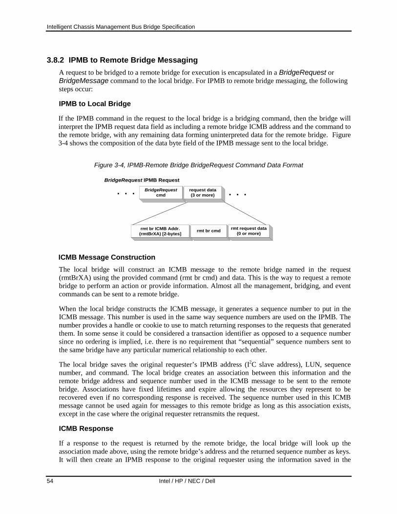
Intelligent Chassis Management Bus Bridge Specification
54 Intel / HP / NEC / Dell
3.8.2 IPMB to Remote Bridge Messaging A request to be bridged to a remote bridge for execution is encapsulated in a BridgeRequest or BridgeMessage command to the local bridge. For IPMB to remote bridge messaging, the following steps occur:
IPMB to Local Bridge
If the IPMB command in the request to the local bridge is a bridging command, then the bridge will interpret the IPMB request data field as including a remote bridge ICMB address and the command to the remote bridge, with any remaining data forming uninterpreted data for the remote bridge. Figure 3-4 shows the composition of the data byte field of the IPMB message sent to the local bridge.
Figure 3-4, IPMB-Remote Bridge BridgeRequest Command Data Format
BridgeRequest IPMB Request
rmt br ICMB Addr.(rmtBrXA) [2-bytes] rmt br cmd rmt request data
(0 or more)
BridgeRequestcmd
request data(3 or more) . . .. . .
ICMB Message Construction The local bridge will construct an ICMB message to the remote bridge named in the request (rmtBrXA) using the provided command (rmt br cmd) and data. This is the way to request a remote bridge to perform an action or provide information. Almost all the management, bridging, and event commands can be sent to a remote bridge.
When the local bridge constructs the ICMB message, it generates a sequence number to put in the ICMB message. This number is used in the same way sequence numbers are used on the IPMB. The number provides a handle or cookie to use to match returning responses to the requests that generated them. In some sense it could be considered a transaction identifier as opposed to a sequence number since no ordering is implied, i.e. there is no requirement that “sequential” sequence numbers sent to the same bridge have any particular numerical relationship to each other.
The local bridge saves the original requester’s IPMB address (I2C slave address), LUN, sequence number, and command. The local bridge creates an association between this information and the remote bridge address and sequence number used in the ICMB message to be sent to the remote bridge. Associations have fixed lifetimes and expire allowing the resources they represent to be recovered even if no corresponding response is received. The sequence number used in this ICMB message cannot be used again for messages to this remote bridge as long as this association exists, except in the case where the original requester retransmits the request.
ICMB Response
If a response to the request is returned by the remote bridge, the local bridge will look up the association made above, using the remote bridge’s address and the returned sequence number as keys. It will then create an IPMB response to the original requester using the information saved in the
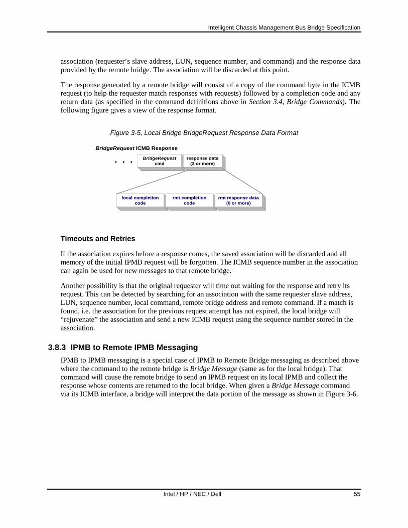
Intelligent Chassis Management Bus Bridge Specification
Intel / HP / NEC / Dell 55
association (requester’s slave address, LUN, sequence number, and command) and the response data provided by the remote bridge. The association will be discarded at this point.
The response generated by a remote bridge will consist of a copy of the command byte in the ICMB request (to help the requester match responses with requests) followed by a completion code and any return data (as specified in the command definitions above in Section 3.4, Bridge Commands). The following figure gives a view of the response format.
Figure 3-5, Local Bridge BridgeRequest Response Data Format
BridgeRequest ICMB Response
local completioncode
BridgeRequestcmd
response data(3 or more). . .
rmt completioncode
rmt response data(0 or more)
Timeouts and Retries
If the association expires before a response comes, the saved association will be discarded and all memory of the initial IPMB request will be forgotten. The ICMB sequence number in the association can again be used for new messages to that remote bridge.
Another possibility is that the original requester will time out waiting for the response and retry its request. This can be detected by searching for an association with the same requester slave address, LUN, sequence number, local command, remote bridge address and remote command. If a match is found, i.e. the association for the previous request attempt has not expired, the local bridge will “rejuvenate” the association and send a new ICMB request using the sequence number stored in the association.
3.8.3 IPMB to Remote IPMB Messaging IPMB to IPMB messaging is a special case of IPMB to Remote Bridge messaging as described above where the command to the remote bridge is Bridge Message (same as for the local bridge). That command will cause the remote bridge to send an IPMB request on its local IPMB and collect the response whose contents are returned to the local bridge. When given a Bridge Message command via its ICMB interface, a bridge will interpret the data portion of the message as shown in Figure 3-6.

Intelligent Chassis Management Bus Bridge Specification
56 Intel / HP / NEC / Dell
Figure 3-6, IPMB-IPMB BridgeRequest Request Data Format
Remote BridgeRequestRequest
rsSA netFn/rsLUN
Bridge Requestcmd
rmt data bytes(3 or more) . . .. . .
cmd data bytes(0 or more)
The rsSA is the IPMB address (I2C address) of the responder on the remote IPMB. Likewise, netFn/rsLUN is the IPMB network function and responder’s LUN. Cmd is the command for the responder. Using this information, the remote bridge creates an IPMB request and sends it to the responder on its local IPMB. In doing so, it generates a sequence number to use for that request on the IPMB.
Similar to the previous section, but on the remote bridge, an association is made between the received request (here having arrived via the ICMB) and the transmitted request (here being sent over the IPMB). The ICMB address of the requesting (local) bridge, and the sequence number of the ICMB received request is associated with the responder’s IPMB address and LUN, the generated sequence number, and command. This association is used to match to the IPMB response from the responder allowing an ICMB response to be generated to the requesting bridge.
As in the previous section, these associations age and the same semantics apply with respect to timeouts and retries.
For completeness sake, the Figure 3-7 shows the complete format of an IPMB to IPMB request from the perspective of the requester on the local IPMB:
Figure 3-7, Full IPMB-to-IPMB BridgeRequest Request Format
rq Slave Addr.(rqSA)
IPMB-to-remote IPMB Requestbr Slave Addr.
(brSA)Bridge / brLUN checksum
rqSeq / rqLUN BridgeRequestcmd
rmtBrXA(2 bytes)
BridgeRequestcmd
rs Slave Addr.(rsSA)
netFn / rsLUN IPMB cmd data bytes(0 or more)
checksum
Figure 3-8 shows the complete format of an IPMB-to-IPMB response from the perspective of the local IPMB from which the request originated. The ICMB response generated by the remote bridge includes the IPMB completion code for the bridged IPMB request, as well as the full contents of the IPMB response data from the remote IPMB node (responder).
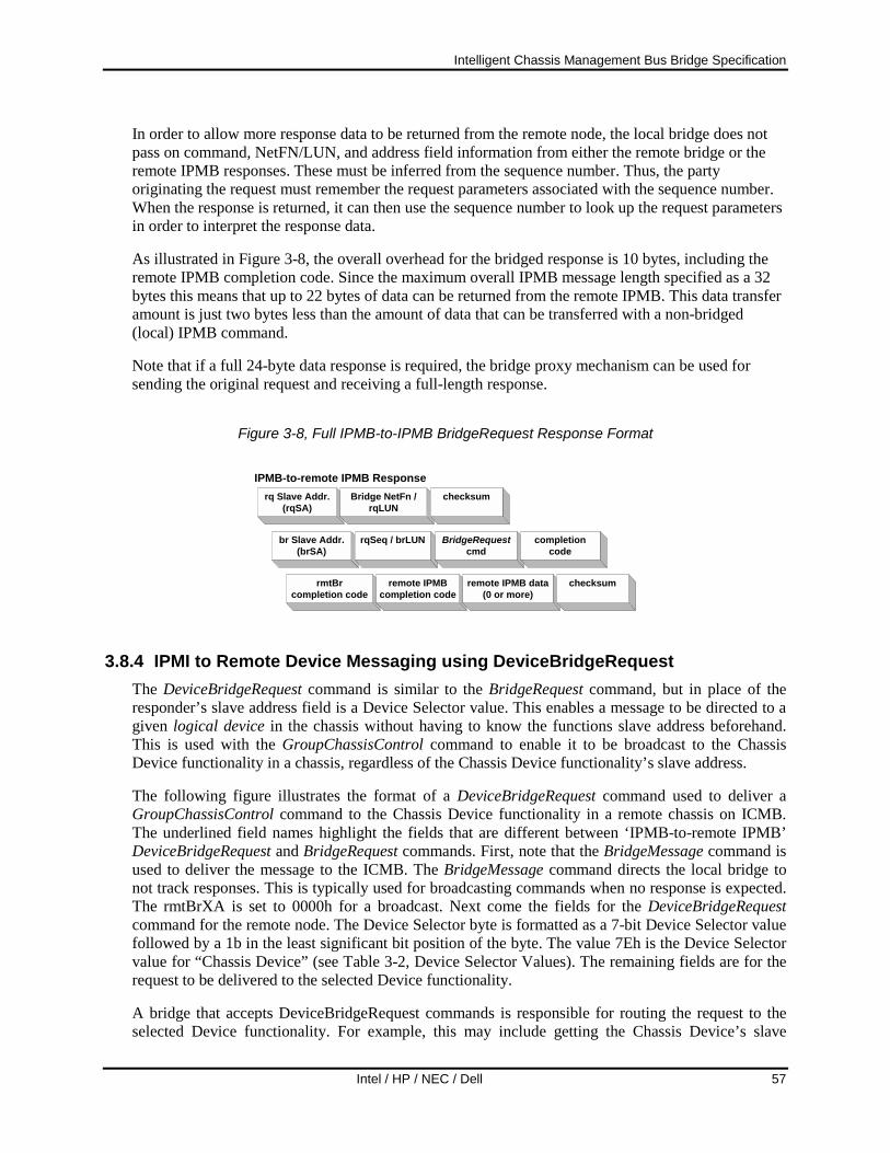
Intelligent Chassis Management Bus Bridge Specification
Intel / HP / NEC / Dell 57
In order to allow more response data to be returned from the remote node, the local bridge does not pass on command, NetFN/LUN, and address field information from either the remote bridge or the remote IPMB responses. These must be inferred from the sequence number. Thus, the party originating the request must remember the request parameters associated with the sequence number. When the response is returned, it can then use the sequence number to look up the request parameters in order to interpret the response data.
As illustrated in Figure 3-8, the overall overhead for the bridged response is 10 bytes, including the remote IPMB completion code. Since the maximum overall IPMB message length specified as a 32 bytes this means that up to 22 bytes of data can be returned from the remote IPMB. This data transfer amount is just two bytes less than the amount of data that can be transferred with a non-bridged (local) IPMB command.
Note that if a full 24-byte data response is required, the bridge proxy mechanism can be used for sending the original request and receiving a full-length response.
Figure 3-8, Full IPMB-to-IPMB BridgeRequest Response Format
br Slave Addr.(brSA)
IPMB-to-remote IPMB Responserq Slave Addr.
(rqSA)Bridge NetFn /
rqLUNchecksum
rqSeq / brLUN BridgeRequestcmd
completioncode
rmtBrcompletion code
remote IPMBcompletion code
remote IPMB data(0 or more)
checksum
3.8.4 IPMI to Remote Device Messaging using DeviceBridgeRequest The DeviceBridgeRequest command is similar to the BridgeRequest command, but in place of the responder’s slave address field is a Device Selector value. This enables a message to be directed to a given logical device in the chassis without having to know the functions slave address beforehand. This is used with the GroupChassisControl command to enable it to be broadcast to the Chassis Device functionality in a chassis, regardless of the Chassis Device functionality’s slave address.
The following figure illustrates the format of a DeviceBridgeRequest command used to deliver a GroupChassisControl command to the Chassis Device functionality in a remote chassis on ICMB. The underlined field names highlight the fields that are different between ‘IPMB-to-remote IPMB’ DeviceBridgeRequest and BridgeRequest commands. First, note that the BridgeMessage command is used to deliver the message to the ICMB. The BridgeMessage command directs the local bridge to not track responses. This is typically used for broadcasting commands when no response is expected. The rmtBrXA is set to 0000h for a broadcast. Next come the fields for the DeviceBridgeRequest command for the remote node. The Device Selector byte is formatted as a 7-bit Device Selector value followed by a 1b in the least significant bit position of the byte. The value 7Eh is the Device Selector value for “Chassis Device” (see Table 3-2, Device Selector Values). The remaining fields are for the request to be delivered to the selected Device functionality.
A bridge that accepts DeviceBridgeRequest commands is responsible for routing the request to the selected Device functionality. For example, this may include getting the Chassis Device’s slave
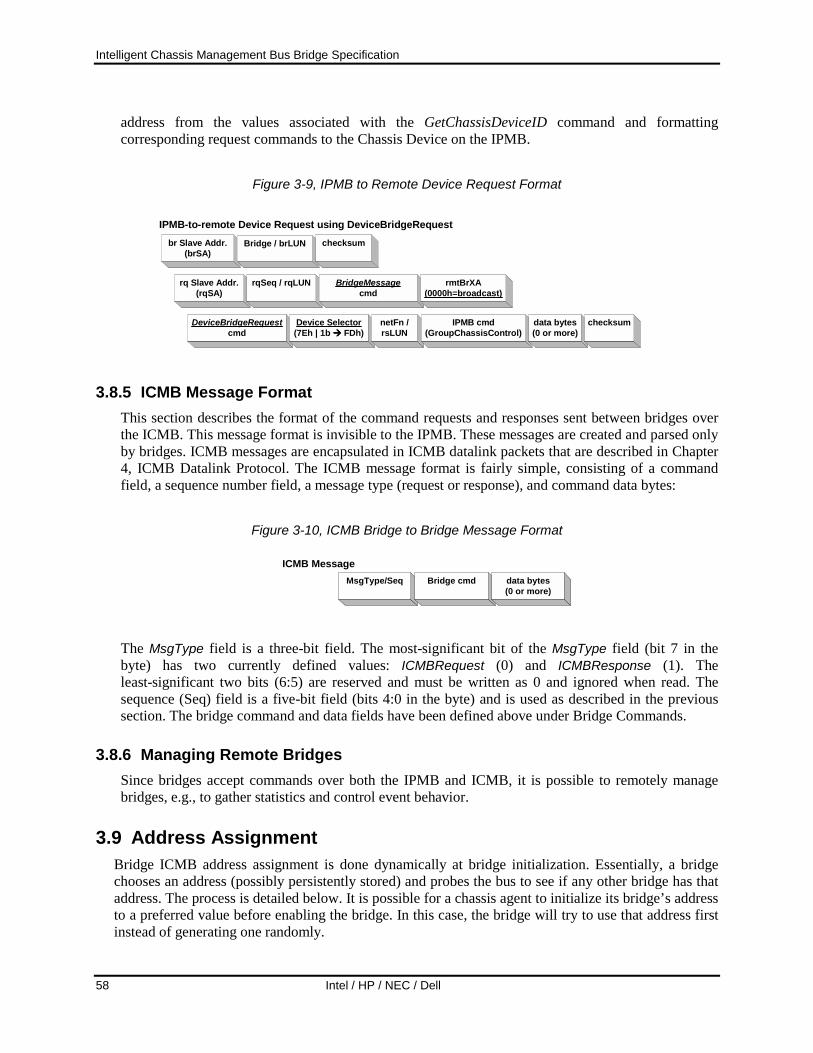
Intelligent Chassis Management Bus Bridge Specification
58 Intel / HP / NEC / Dell
address from the values associated with the GetChassisDeviceID command and formatting corresponding request commands to the Chassis Device on the IPMB.
Figure 3-9, IPMB to Remote Device Request Format
DeviceBridgeRequestcmd
rq Slave Addr.(rqSA)
IPMB-to-remote Device Request using DeviceBridgeRequestbr Slave Addr.
(brSA)Bridge / brLUN checksum
rqSeq / rqLUN BridgeMessagecmd
Device Selector(7Eh | 1b """" FDh)
netFn /rsLUN
IPMB cmd(GroupChassisControl)
data bytes(0 or more)
checksum
rmtBrXA(0000h=broadcast)
3.8.5 ICMB Message Format This section describes the format of the command requests and responses sent between bridges over the ICMB. This message format is invisible to the IPMB. These messages are created and parsed only by bridges. ICMB messages are encapsulated in ICMB datalink packets that are described in Chapter 4, ICMB Datalink Protocol. The ICMB message format is fairly simple, consisting of a command field, a sequence number field, a message type (request or response), and command data bytes:
Figure 3-10, ICMB Bridge to Bridge Message Format
ICMB MessageMsgType/Seq Bridge cmd data bytes
(0 or more)
The MsgType field is a three-bit field. The most-significant bit of the MsgType field (bit 7 in the byte) has two currently defined values: ICMBRequest (0) and ICMBResponse (1). The least-significant two bits (6:5) are reserved and must be written as 0 and ignored when read. The sequence (Seq) field is a five-bit field (bits 4:0 in the byte) and is used as described in the previous section. The bridge command and data fields have been defined above under Bridge Commands.
3.8.6 Managing Remote Bridges Since bridges accept commands over both the IPMB and ICMB, it is possible to remotely manage bridges, e.g., to gather statistics and control event behavior.
3.9 Address Assignment Bridge ICMB address assignment is done dynamically at bridge initialization. Essentially, a bridge chooses an address (possibly persistently stored) and probes the bus to see if any other bridge has that address. The process is detailed below. It is possible for a chassis agent to initialize its bridge’s address to a preferred value before enabling the bridge. In this case, the bridge will try to use that address first instead of generating one randomly.

Intelligent Chassis Management Bus Bridge Specification
Intel / HP / NEC / Dell 59
3.9.1 Dynamic Assignment When a bridge is transitioned from the Disabled to Enabled state, the following process is followed:
1. The bridge transitions to the Assigning state.
2. If the bridge’s initial address has not been previously set via a SetBridgeAddress command, the bridge generates a random address within the set of legal ICMB addresses.
3. The bridge sends a GetBridgeAddress command to its own address over the ICMB. This is to test for an address collision. This is sent out periodically until either a response is received or the retry count is exhausted. (See Section 7, Timing and Retry Specifications, for interval and retry count specifications.)
4. If no response is received for any of the probes, the bridge datalink protocol assumes the address it valid and transitions from the Assigning state to the Enabled state ending the dynamic assignment process. A bridge may persistently store addresses chosen by this algorithm to be used during the next address assignment phase.
5. If a response is received, the address is abandoned, a new number is randomly generated and the bridge continues at Step 3.
3.9.2 Address Collision Detection It is possible that due to various reasons two bridges on the same bus segment think they have the same address. This can cause confusion if commands to one chassis are intercepted and acted on by another. Several behaviors are used to avoid and recover from address collisions:
• Each bridge watches incoming packets and checks to see if the source address is the same as its own. If both the source and destination address is its own, a bridge will process the command normally since this is the way a bridge probes to see if its address is already in use. If only the source address is its own, it will immediately stop accepting command packets and re-initialize itself, going through the address assignment phase again. If its address changes due to this process, it will be discovered during the next discovery cycle.
• After the assignment algorithm has chosen an address, a bridge will continue to periodically send out GetBridgeAddress requests to its own address until it has received a SetDiscovered request.
• After completing the address assignment algorithm, a bridge will ignore ICMB requests except for Management and Bridge Chassis commands until it has received a SetDiscovered request.
3.10 Bridge API It is expected that the bridge functionality may co-exist with other instrumentation in a platform controller. The network function field in IPMB requests allows bridge targeted requests to be easily recognized and passed to the bridge subsystem by the controller command processor. The bridge has its own command set and command interpreter although it is possible that some parts of the main controller command processor could be used.

Intelligent Chassis Management Bus Bridge Specification
60 Intel / HP / NEC / Dell
3.11 Bridge Performance and Capacity This section discusses the expected and required performance characteristics of ICMB. It also makes recommendations of values for the various timers and limits on outstanding transactions.
3.11.1 Latency Total ICMB bridging latency is a function of the datalink latency (arbitrating for the bus and the actual flight time of a packet), and queuing delays in the bridge due to other bridge device workload and IPMB delays.
A bridge should not take more than 5 ms (BridgePropagation) from reception of an IPMB request or response (to be bridged to the ICMB) to its queuing by the ICMB datalink protocol module. The delay from that point to its actual transmission is a function of ICMB loading and arbitration success.
Similarly, a bridge should not take more than 5 ms (BridgePropagation) from reception of an ICMB request or response (to be bridged to the IPMB) to its queuing by the IPMB protocol module. The delay from that point to its actual transmission is a function of IPMB loading and arbitration success.
Transmission time is a fixed function of individual bus (IPMB, ICMB) characteristics. For most implementations, ICMB arbitration will be won on the first try (since one piece of system management software will be driving requests onto the bus).
Assuming an average ICMB message length of about 16 characters with an inter-character delay of 0. It will take about 10 ms for the message to be transferred on the bus. At the remote end, assume the remote node will respond within 20 ms. Adding together the times, we get:
5 ms request propagation through local bridge 10 ms request transmission on ICMB
5 ms request propagation through remote bridge 20 ms response time from remote management controller
5 ms response propagation through remote bridge 10 ms response transmission on ICMB
5 ms response propagation through local bridge 60 ms nominal bridged request to response time
These are conservative values. The actual nominal request-to-response times should be significantly better.
The worst-case can be significantly longer, and dependent on whether the remote node is being requested to perform accesses such as writes to slow devices such as SEEPROMs.
A busy ICMB and long ICMB messages can stretch the arbitration time to get to the bus. Assuming that three tries at arbitration are required, and that the ICMB messages are 35 bytes instead of 16 bytes, yields about 60 ms to get the bus, and perhaps another ~20 ms to send the message. The IPMB currently has defined a retry timeout of 60 ms for local transactions. Three retries for local access to the IPMB would thus take 180 ms, worst case. The following table sums up this scenario:

Intelligent Chassis Management Bus Bridge Specification
Intel / HP / NEC / Dell 61
5 ms request propagation through local bridge 60 ms arbitration for near 100% occupied bus with long packet
traffic 20 ms request transmission on ICMB
5 ms request propagation through remote bridge 180 ms response time from remote management controller
5 ms response propagation through remote bridge 60 ms arbitration for near 100% occupied bus with long packet
traffic 20 ms response transmission on ICMB
5 ms response propagation through local bridge 360 ms ‘worst case’ bridged request to response time
A System Management Software application could very conservatively implement a fixed 500 to 600 ms timeout and be assured that the remote application has had ample time to respond. Or, it could take a more performance-oriented approach, implementing a sliding timeout of 125 ms for the first response timeout, 250 ms for a second response timeout, and 500 ms for a third. Finally, an application could adaptively adjust timeouts by collecting response statistics for the bus.
3.11.2 Resource Utilization Memory utilization of a bridge is directly proportional to the amount of concurrent activity. The more simultaneous request/response IPMB activity, the more message buffers are needed to queue packets and hold information necessary to complete the transactions. Inappropriate sizing of these resources can lead to excess capacity or dropping of requests, requiring a more expensive implementation than necessary or degraded performance due to higher level protocol retries to successfully complete the operation.
Currently the IPMB places a limit of one outstanding request/response transaction between IPMB nodes. This limits simultaneous outgoing traffic to the maximum number of requesters on a bridge’s IPMB.
The limit on incoming traffic relates to the number of potential senders on the ICMB segment and the type of chassis. A peripheral chassis need only deal with requests from management chassis. Peripheral chassis do not talk to each other except potentially during address assignment.
A bridge must have enough resources to simultaneously support at least four inbound (ICMB to IPMB) and four outbound (IPMB to ICMB) transactions.
This includes buffering for messages as well as auxiliary data structures used in transaction bookkeeping (associations). Messages associated with discovery count as inbound transactions if being received via the ICMB and outbound if being driven via the IPMB.

Intelligent Chassis Management Bus Bridge Specification
62 Intel / HP / NEC / Dell
4. ICMB Datalink Protocol This chapter describes the ICMB datalink protocol and includes the packet format, addressing, and arbitration. A bus state transition graph is given with a description of the datalink protocol. Specific values for timings follows in Chapter 7, Timing and Retry Specifications.
The ICMB datalink protocol provides for the transmission of data in packets from bridge to bridge over the ICMB hardware, a multi-drop RS-485 network. It can be described as an unreliable datagram protocol; there is no guarantee by the datalink protocol that a packet will reach its destination. Since the ICMB network is a bus, it is a broadcast network. All bridges see all traffic on the network. Received packets not addressed either to the receiving bridge or to the broadcast address are discarded.
Packet transmission is asynchronous with bridges sending when they have packets to send (no bus master, tokens or time division). In standard networking nomenclature, the ICMB is a CSMA (carrier sense, multiple access) network. This means that the bridge can detect when another bridge is sending, allowing it to avoid collisions by not sending in the middle of another bridge’s transmission, and that the network supports the ability of multiple bridges to be bus masters. However, a sending bridge cannot detect if another bridge is also sending. That is, there is no collision detection by the senders. A collision can happen if there is an arbitration failure and more than one bridge believes that it has acquired the right to send on the bus. Any receivers may be able to detect the collision, but the senders will not.
4.1 Bus States The ICMB has a very simple state description. It has two basic states: Arbitrating and Sending.
• The Arbitrating state is where bridges arbitrate for the right to send on the bus. The arbitration process is discussed in detail in Section 4.3.1, Arbitration Protocol. If no bridges want to send, the bus will remain idle.
• The Sending state is where a bridge is sending a packet. A bridge has to win arbitration to enter this state. The bus will enter the Arbitrating state ArbDelay after the packet-ending character has been sent.
A bridge may have a more complicated internal representation of the bus state to allow for tracking of bus state transitions and because a bridge will behave differently depending on whether it is sending or receiving a packet.
4.2 Packet Framing and Packet Format ICMB packets consist of a series of eight bit bytes. The ICMB uses standard RS-232 UART character framing. The bus operates at 19.2 Kbps with 8-bit characters, 1 start bit, 1 stop bit, and no parity. The low-order bit of a character is sent first. Packets are framed in a way that allows the start and end of a packet to be easily distinguished. Certain characters have been chosen as framing characters and the protocol guarantees that those characters will not appear on the bus except to mark packet boundaries (excluding a HW or SW failure).
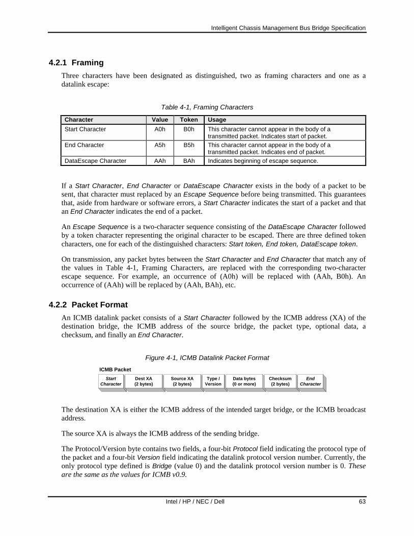
Intelligent Chassis Management Bus Bridge Specification
Intel / HP / NEC / Dell 63
4.2.1 Framing Three characters have been designated as distinguished, two as framing characters and one as a datalink escape:
Table 4-1, Framing Characters
Character Value Token Usage Start Character A0h B0h This character cannot appear in the body of a
transmitted packet. Indicates start of packet. End Character A5h B5h This character cannot appear in the body of a
transmitted packet. Indicates end of packet. DataEscape Character AAh BAh Indicates beginning of escape sequence.
If a Start Character, End Character or DataEscape Character exists in the body of a packet to be sent, that character must replaced by an Escape Sequence before being transmitted. This guarantees that, aside from hardware or software errors, a Start Character indicates the start of a packet and that an End Character indicates the end of a packet.
An Escape Sequence is a two-character sequence consisting of the DataEscape Character followed by a token character representing the original character to be escaped. There are three defined token characters, one for each of the distinguished characters: Start token, End token, DataEscape token.
On transmission, any packet bytes between the Start Character and End Character that match any of the values in Table 4-1, Framing Characters, are replaced with the corresponding two-character escape sequence. For example, an occurrence of (A0h) will be replaced with (AAh, B0h). An occurrence of (AAh) will be replaced by (AAh, BAh), etc.
4.2.2 Packet Format An ICMB datalink packet consists of a Start Character followed by the ICMB address (XA) of the destination bridge, the ICMB address of the source bridge, the packet type, optional data, a checksum, and finally an End Character.
Figure 4-1, ICMB Datalink Packet Format ICMB Packet
StartCharacter
Dest XA(2 bytes)
Source XA(2 bytes)
Type /Version
Data bytes(0 or more)
Checksum(2 bytes)
EndCharacter
The destination XA is either the ICMB address of the intended target bridge, or the ICMB broadcast address.
The source XA is always the ICMB address of the sending bridge.
The Protocol/Version byte contains two fields, a four-bit Protocol field indicating the protocol type of the packet and a four-bit Version field indicating the datalink protocol version number. Currently, the only protocol type defined is Bridge (value 0) and the datalink protocol version number is 0. These are the same as the values for ICMB v0.9.

Intelligent Chassis Management Bus Bridge Specification
64 Intel / HP / NEC / Dell
4.2.2.1 ICMB Checksum For data integrity purposes, each packet has a checksum. The checksum is a 16-bit 2’s complement sum to ones checksum (data+checksum=0xffff) calculated over all the characters in the packet excluding the framing characters (Start and End Characters) and the checksum itself. In addition, the number of characters being checksummed, plus one, is added in to the checksum to make the checksum more robust in the face of dropped characters. For transmission, the checksum is calculated before the packet contents have been escaped (to remove distinguished characters). For reception, the checksum is calculated after any escape sequences have been replaced with their representative characters. The checksum is thus: (data + data_length + 1 + checksum = 0xffff)
4.2.3 Bridged ICMB-to-IPMB Request Message Figure 3-7, Full IPMB-to-IPMB BridgeRequest Request Format, illustrates the format of an IPMB request message that is to bridge a request to a remote IPMB. The following figure shows the format of the corresponding message that the local bridge puts out onto the ICMB and is received by the remote bridge. DestXA and SourceXA are the addresses of the transmitting (local) and receiving (remote) bridges, respectively. The BridgeRequest command tells the remote bridge to store sequence number and bridge address information that will be used to create an ICMB message for routing the corresponding IPMB response back to the bridge that originated the request.
Figure 4-2, Full ICMB-to-IPMB Request Message Format
Data for IPMB Request Messagers Slave Addr.
(rsSA)netFn (even)
/ rsLUNIPMB cmd Data bytes
(0 or more)
ICMB PacketStart
CharacterDestXA
(2 bytes)SourceXA(2 bytes)
Protocol (0) /Version (0)
Data bytes(0 or more)
Checksum(2 bytes)
EndCharacter
ICMB MessageMsgType (000b=Rq)
/SeqBridgeRequest
cmdData bytes(0 or more)
4.2.4 ICMB-to-IPMB Response Message Figure 3-7, Full IPMB-to-IPMB BridgeRequest Request Format, illustrates the format of an IPMB request message that is to bridge a request to a remote IPMB. The following figure shows the format of the corresponding response message that the local bridge receives from the remote bridge. In this case the DestXA and SourceXA values are swapped. DestXA is now the address of the bridge that originated the request, and SourceXA is the address of the responding bridge. The MsgType field of the ICMB message is 1xx, indicating an ICMB Response. Similarly, the NetFn field that is part of the IPMB data is odd, indicating an IPMB response.

Intelligent Chassis Management Bus Bridge Specification
Intel / HP / NEC / Dell 65
Figure 4-3, Full ICMB-to-IPMB Response Message Format
Data for IPMB Response Messagers Slave Addr.
(rsSA)netFn (odd)
/ rsLUNIPMBcmd
ICMB PacketStart
CharacterDestXA
(2 bytes)SourceXA(2 bytes)
Protocol (0) /Version (0)
Data bytes(0 or more)
Checksum(2 bytes)
EndCharacter
ICMB MessageMsgType (100b=Rs)
/SeqBridgeRequest
cmd
CompletionCode
Data bytes(0 or more)
CompletionCode
Data bytes(0 or more)
4.2.5 ICMB Event Message Format The following is uses the format of an ICMB Event Message as an example of the format of an ICMB bridge-to-bridge message. This message will typically be broadcast. Therefore, the DestXA field will be set to the broadcast external node address.
Figure 4-4, Full ICMB Event Message Format
ICMB PacketStart
CharacterDestXA(2 bytes)
SourceXA(2 bytes)
Protocol (0) /Version (0)
Data bytes(0 or more)
Checksum(2 bytes)
EndCharacter
ICMB MessageMsgType (000b=Rq)
/SeqSendICMBEvM
cmdeventCode eventCount
4.2.6 IPMB Event Message for SMS In a system that has a BMC, a bridge that receives an ICMB SendICMBEventMessage command forwards a corresponding IPMB Event Message to System Management Software (Peripheral chassis do not typically accept ICMB Event Messages).
The following figure illustrates the format of the event message that the bridge generates on the IPMB for delivery to system management software. For IPMI v0.9 or v1.0 systems, the message is sent to the BMC’s slave address (20h) and the SMS LUN (10b). The EventSourceXA field is the 2-byte ICMB address of the bridge that generated the event. The Event Code and Event Count fields are extracted from the SendICMBEventMessage command. See Section 3.4.4.1, Send ICMB Event Message, and Section 3.4.4.4, Get Bridge Event Count for more information on the Event Code and Event Count fields, respectively. The remaining fields are per the IPMB protocol specification. Figure 4-5, IPMB Message to System Mgmt. Software for ICMB Events, shows the format of the IPMB message as it is received by a BMC from the IPMB. Note that as of this writing, the BridgeEvent command has not yet been incorporated into the main IPMI specification. This does not impact the BMC’s ability to pass this command to system software, however, since the BMC passes any IPMB command that is received via LUN 10b on to system software.

Intelligent Chassis Management Bus Bridge Specification
66 Intel / HP / NEC / Dell
Figure 4-5, IPMB Message to System Mgmt. Software for ICMB Events
IPMB Message
EvMrev (10h) EventCode
Event Source XA(2 bytes)
EventCount
rsSA(20h)
NetFn = sensor-event/ rsLUN (10b)
Checksum
rqSA rqSeq /rqLUN
BridgeEvent (03)cmd
Checksum
4.3 Arbitration and Collisions If multiple ICMB bridges determine they have the right to send on the bus and start sending, their packets will collide. The ICMB implementation does not detect this. In all likelihood, the messages will be corrupted and any bridges receiving at the time will get a garbled transmission, tossing it all due to either framing errors or checksum mismatch. The IPMB implements reliability via retries, so most likely the requester will try again and get through. Collisions are not fatal, but reduce overall bus and system performance by both using bus bandwidth nonproductively and introducing delays due to retransmission timeouts.
Instead of concentrating on detecting collisions, the ICMB design concentrates on reducing their probability to the point where collisions are a small performance issue. This is done via an arbitration scheme that reduces the window of time where two or more bridges might simultaneously determine they have the right to send on the bus to less than approximately ArbSample microseconds. (See Section 7, Timing and Retry Specifications, for timing values.)
4.3.1 Arbitration Protocol There are two basic bus states where arbitration can occur: when the bus is idle and immediately after a packet has been sent. The most interesting state is the second one. The probability of collision when the bus is idle is relatively low. While a packet is being sent, however, potential senders can be queuing up-waiting for their turn to send. If no arbitration mechanism is used, the probability of multiple bridges trying to send simultaneously is relatively high during busy times.
The basic concept of the arbitration protocol is that a bridge waits a random amount of time (within a minimum and maximum limits) and if no other bridge has done so first, drives an active-low arbitration pulse onto the bus for a different random amount of time. The first bridge to drive the bus low wins. If there is a tie, the last bridge to stop driving the bus, (the one with the longer arbitration pulse) wins.
The arbitration process can be driven solely by firmware, or can be hardware assisted. Most firmware-based implementations will benefit from being able to have hardware connections that allow the high-to-low transition of the signal line generate an interrupt.
The arbitration protocol is as follows:
1. There are two possible conditions that indicate when arbitration can be started: Receiving an End Character, or seeing the bus idle for an interval greater than BusFreeTimeout (refer to Section 7,

Intelligent Chassis Management Bus Bridge Specification
Intel / HP / NEC / Dell 67
Timing and Retry Specifications). If the BusFreeTimeout interval has expired, the arbitration process can proceed immediately with Step 4.
2. If an End Character has just been received, each bridge will delay a minimum amount of time, ArbDelay, before starting the arbitration process. This delay is to ensure that the sender of the previous packet has had time disable its transmitter and that other arbitrating senders have entered their arbitrating state.
All bridges, whether wanting to send or not, must continuously monitor the bus when the bus is in the Arbitrating state.
3. Each bridge that wants to transmit will wait for a random amount of time (ArbPulseStart) before driving the arbitration pulse onto the bus (Step 4). During this wait interval, each bridge will continuously sample the signal state of the bus. (The maximum sampling interval is given by the ArbSample parameter.)
• A bridge loses the arbitration process if it detects the bus being driven low while waiting to start its arbitration pulse. The bridge will re-arbitrate at the next opportunity
• If the bus has not been driven low during this interval, it goes on to Step 3.
4. The bridges reaching this step will enable their ICMB transceivers and drive an arbitration pulse onto the bus for a random duration within the range specified by ArbPulseWidth. They then briefly drive the bus high for the PreCharge interval, disable their transceivers and sample the bus signal state. The different arbitration pulse widths are quantified to take into account the time between when a bridge disables its transceiver and sample the bus state.
• A bridge loses arbitration if it detects the bus has transitioned to a low state before the conclusion of the ArbLoss interval following the PreCharge pulse. It will try again at the next arbitration opportunity.
• If the bus is in the high (default) state, a bridge assumes that it has won the right to send and immediately starts sending its packet.
Bridges are required to track bus state, including arbitration periods, even if they have no packets to send. This keeps the bridges in sync with respect to bus state and allows them to know when the bus is idle or busy.
If a bridge is given a packet to send during an arbitration interval (whether other bridges are currently arbitrating or not), it will wait until either the next arbitration interval or the bus enters the idle state.
The arbitration pulse and precharge pulse transitions may cause listening UARTs to think they have received a character prior to the Start Character. Therefore, an implementation of this mechanism should:
• From a receiving perspective, be able to deal with extraneous characters at the start of a packet.
• From a transmitting perspective, a bridge that wins arbitration must wait for the PktStartMin interval before transmitting the first (start) character of its packet.
Figure 4-6 shows a simple example of the arbitration process. The first signal figure, labeled ‘bus’, is the sum of the outputs of the all bridges on the bus and represents the net electrical state of the bus as

Intelligent Chassis Management Bus Bridge Specification
68 Intel / HP / NEC / Dell
would be seen by a receiver. The signals labeled Bridge 1, Bridge 2, and Bridge 3 indicate the states to which the respective bridges are individually driving the bus. The RS-485 transceivers are designed such that a ‘1’ state will be maintained when the transmitters are disabled (high impedance, sometimes referred to as the ‘tri-stated’ or ‘tri-state’ condition).
In this example, three bridges, 1, 2 and 3, arbitrate for the bus. Bridge 1 is shown as being the bridge that last had the bus and is concluding its packet. Each bridge starts arbitration by waiting a random time after seeing the end of a packet to start their arbitration pulses. Bridge 1 notes that some other bridge (in this case both bridges 2 and 3) has driven the bus low before it has had the opportunity to start its arbitration pulse and concludes it has lost. (The point at which Bridge 1 would have driven its pulse is illustrated as a dotted line pulse on the Bridge 1 signal in the figure.)
After their arbitration pulse wait interval ends, bridges 2 and 3 simultaneously (within ArbSample) start driving their arbitration pulses on the bus. Bridge 2 ends its arbitration pulse first and tests the bus state. Bridge 2 sees that the bus is still low (still being driven by bridge 3) and concludes it has lost arbitration. Bridge 3 continues driving and at the end of its arbitration interval also stops driving the bus and tests the bus state. The state is now high and Bridge 3 assumes that it has won, allowing it to start sending its packet.
Figure 4-6, Arbitration Timing & Example
ArbPulseWidth
Tri-state
Tri-state
Endof
Packet
ArbDelay
Startof
Packet
Bus
Bridge 2
Bridge 3
XcvrOffDelay
Bridge 1
Precharge
ArbSample
ArbPulseStart
Tri-state
Dashed line illustrateswhere bridge 1 might haveput out an arbitration pulseif it hadn't seen otherbridges already driving thesignal line low.
PktStartMin
ArbLoss
Stop
Bit
Not to Scale
Star
t Bit
START
STARTStar
t Bit
Tri-state
Tri-state
END
ENDdidn't put out arbpulse becauseanother controller putout pulse first
st arbitration byetecting anotherontroller was stillsserting the arb pulse
on arbitration byolding arb pulse longeran other bridges

Intelligent Chassis Management Bus Bridge Specification
Intel / HP / NEC / Dell 69
4.3.2 Collision Behavior A collision is defined as the condition where two or more bridges simultaneously conclude that they have won arbitration. A collision is not detectable by bridges while they are transmitting, and depending on the relative lengths of the packets, they may not know afterwards that it has occurred.2
Receiving bridges may see partial packets and or gaps in packets depending on how the characters being sent interfere with each other. Packet framing characters may be lost or generated by the interference. Collisions, then, show up as packet errors that are caught by the packet data integrity checks.
A collision that corrupts either a request or a response causes the message to be rejected by either by the responder or the requester, respectively. In either case, the requester typically times out waiting for the response and retries the request. The combination of packet data integrity checks and datalink protocol bus state recovery (e.g. retries) will return the bus to a known state.
The probability of a collision relates directly to the likelihood that more than one bridge will attempt to arbitrate for the bus after a given message, that those bridges will start their arbitration pulses within ArbSample of one another, and that the bridges will select the same arbitration pulse width.
While it’s highly unlikely that two firmware implementations would line up within ArbSample of one another, a hardware-based arbitration may be able to do this repeatedly. There are 128 different combinations of ArbPulseStart and ArbPulseWidth. If the selection of intervals were truly random the possibility of any two bridges colliding would be one in 128-if they were competing for the same arbitration opportunity. Note that, once address resolution has taken place, most requests will be initiated by system management software from a single system. Thus the net likelihood of collisions is based on the design of that software. If the software avoids generating overlapping requests to multiple systems, the likelihood of collisions during operation is significantly reduced.
4.3.3 Arbitration Pulse Generation This section describes recommendations for implementing the arbitration pulse. Other methods may be used without violating conformance with this specification.
There are two intervals that define the arbitration pulse, the pulse start interval (ArbPulseStart) and the pulse width (ArbPulseWidth). These intervals vary in units of ArbIncrement.
There are sixteen possible intervals of ArbPulseStart, and eight possible intervals for ArbPulseWidth. This yields 128 different arbitration pulses.
The goal is to obtain a random selection of arbitration pulses between successive attempts to arbitrate for the bus.
2 A bridge may conclude that a collision occurred if, after transmitting, it sees additional characters and an End Character, but no Start Character, following its packet. This collision detection mechanism is not reliable, and only covers a bridge that is sending a packet for a short duration than another bridge. In general, it is best to simply assume that transmitting bridges cannot detect collisions. It is recognized that it is possible to create a modified hardware interface that includes the ability to monitor the bus state during transmission. This would typically require a separate receiver connected on the bus-side of the interface past any series resistors between the bus and the transmitter, or a transceiver with similar intrinsic characteristics. This would potentially allow detecting mismatches between the transmitted and received bits that could be used to cause the sender to abort the transmission and retry on the next arbitration opportunity. The design and implementation of such a modified interface is beyond the scope of this specification.

Intelligent Chassis Management Bus Bridge Specification
70 Intel / HP / NEC / Dell
Ideally, bridges would include true-random number generation capability that would be part of the hardware-but this is not typically available for low-cost microcontroller implementations. In lieu of such a capability, one mechanism is for the bridge generate these intervals based on a 7-bit field extracted from a firmware-based 16-bit pseudo-random number generator. The selection of the pseudo-random number generation algorithm is left to the implementer.
The pseudo-random number generator should be advanced for each arbitration loss on that message. The random number generator should be periodically advanced between arbitration or re-seeded between arbitration attempts in place of simply advancing the counter on the first attempt. A free running 16-bit counter running at a 100 kHz or higher rate is a reasonable source for reseeding the generator.
To reduce the possibility that identical controllers come up in synch when devices power up, it is recommended that the initial seed of the random number generator should be derived from the bridge address or other unique number. Another option is to use a free-running counter, or other hardware that will produce a number that varies between controllers.
4.4 Connector ID Signal Generation The timing for the Connector ID signal is shown in Figure 4-7, Connector ID Signal Timing, below. The timing intervals are specified in Table 7-2, Arbitration Timing Specifications.
The Connector ID is tri-stated between packets. The signal is driven to ‘0’ during PktStartMin by the bridge that has won arbitration of the ICMB. While the signal is only needed for the GetConnectorID request, it can be asserted during requests and responses for any command. This is so transmission firmware does not need to differentiate which command is being sent, and whether the transmission is for a request or response.
The Connector ID signal is deasserted at the end of the packet. Prior to the signal being tri-stated, a pre-charge pulse is generated to get the signal into its idle ‘1’ state. The precharge pulse must start during ArbDelay.
A responder that is sampling the state of the Connector ID signal can do so during any time from the start to the end of the packet. I.e. during the reception of packet characters. This sampling should be done multiple times or debounced in order to reduce the possibility that a noise spike could be interpreted as a Connector ID signal assertion.
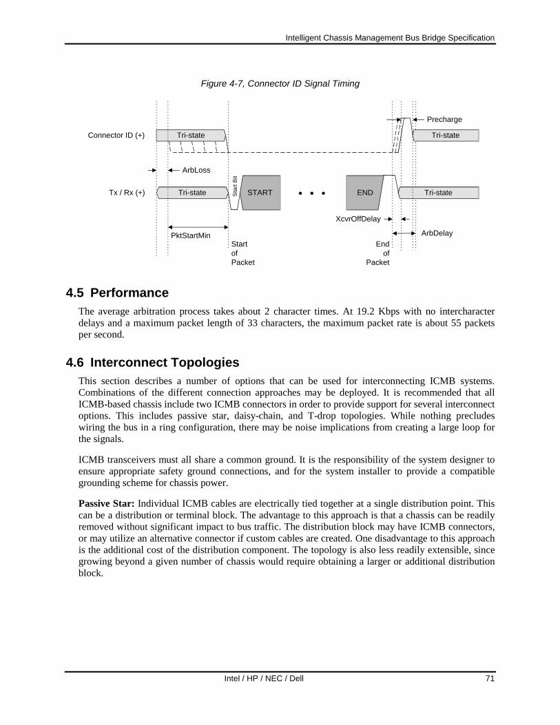
Intelligent Chassis Management Bus Bridge Specification
Intel / HP / NEC / Dell 71
Figure 4-7, Connector ID Signal Timing
Endof
Packet
ArbDelay
XcvrOffDelay
Tri-stateTri-state
StartofPacket
PktStartMin
ArbLoss
STARTStar
t Bit
END
Precharge
Tri-state Tri-stateConnector ID (+)
Tx / Rx (+)
4.5 Performance The average arbitration process takes about 2 character times. At 19.2 Kbps with no intercharacter delays and a maximum packet length of 33 characters, the maximum packet rate is about 55 packets per second.
4.6 Interconnect Topologies This section describes a number of options that can be used for interconnecting ICMB systems. Combinations of the different connection approaches may be deployed. It is recommended that all ICMB-based chassis include two ICMB connectors in order to provide support for several interconnect options. This includes passive star, daisy-chain, and T-drop topologies. While nothing precludes wiring the bus in a ring configuration, there may be noise implications from creating a large loop for the signals.
ICMB transceivers must all share a common ground. It is the responsibility of the system designer to ensure appropriate safety ground connections, and for the system installer to provide a compatible grounding scheme for chassis power.
Passive Star: Individual ICMB cables are electrically tied together at a single distribution point. This can be a distribution or terminal block. The advantage to this approach is that a chassis can be readily removed without significant impact to bus traffic. The distribution block may have ICMB connectors, or may utilize an alternative connector if custom cables are created. One disadvantage to this approach is the additional cost of the distribution component. The topology is also less readily extensible, since growing beyond a given number of chassis would require obtaining a larger or additional distribution block.

Intelligent Chassis Management Bus Bridge Specification
72 Intel / HP / NEC / Dell
Figure 4-8, Passive Star Interconnect
ChassisA
ChassisB
ChassisC
ChassisD
Daisy-chain: Each chassis is provided with two ICMB connectors that are electrically tied together inside the chassis. Individual systems are cabled together by connecting cables as shown in the following figure. To remove a chassis for servicing, the bus may need to be temporarily broken and the removed chassis cabled around, as illustrated by the dotted line in the following figure. This approach is simple and low-cost, but may take longer to service-potentially leading to temporary bus disruptions. It also may be prone to servicing errors where bus segments are accidentally left disconnected. Adding a new chassis to the bus is simply a matter of getting an additional cable, and then linking the new chassis into the bus.
Figure 4-9, Daisy-chain Interconnect
ChassisA
ChassisB
ChassisC
ChassisD
T-drop: A ‘backbone’ cable, with multiple tee’s for connecting chassis is provided, as illustrated in the following figure. This approach may be convenient for relatively fixed installations. The advantages are reduced cable lengths and better cable dressing. This may result in a significantly cleaner installation, particularly in a rack. In general, the approach is less flexible than either the daisy-chain or passive star approach.

Intelligent Chassis Management Bus Bridge Specification
Intel / HP / NEC / Dell 73
Figure 4-10, T-drop Interconnect
ChassisA
ChassisB
ChassisC
ChassisD
4.7 ICMB Cabling Topology Determination The Connector ID signal is an optional point-to-point signal that, if implemented, allows software to send commands to chassis’ on the ICMB and determine their interconnection topology. A chassis that places a GetICMBConnectionID request on the ICMB asserts the Connector ID signal on all of its ICMB connectors after it has won arbitration of the bus (see Figure 4-7, Connector ID Signal Timing).
Chassis’ that accept the GetConnectionID command must capture the state of the Connector ID signal while the GetConnectionID command is being transferred on the ICMB. This allows them to return the captured state in the response to a GetICMBConnectionID request. Since the Connector ID signal is point-to-point, only chassis’ that are directly connected to the chassis that issued the GetICMBConnectionID command will see the Connector ID signal asserted.
The SendICMBConnectionID request message can either be received via IPMB or ICMB. In either case, the bridge takes the ICMB address parameter from the SendICMBConnectionID command and generates a corresponding GetICMBConnectionID request to the specified address onto the ICMB.
Assume there are three systems, A, B, and C, that are interconnected daisy-chain style as shown in the following figure. When received via the IPMB, the SendICMBConnectionID command allows system ‘A’ to determine that it talks to systems B and C through their #1 connectors. But this does not tell system ‘A’ that it got to system ‘C’ by first going through system ‘B’.
The SendICMBConnectionID command allows system ‘A’ to direct another system to report how it is talking to the other systems on the bus. For example, this allows system ‘A’ to determine that system ‘C’ can talk to system ‘B’ via system B’s #2 connector.

Intelligent Chassis Management Bus Bridge Specification
74 Intel / HP / NEC / Dell
Figure 4-11, Get ICMB Connection ID, Send ICMB Connection ID example
BA
1 2 1 2
C
1 2
Get ICMB Connection ID Rq
Get ICMB Connection ID Rq
Get ICMB Connection ID Rs (ID=1)
Get ICMB Connection ID Rs (ID=1)
BA
1 2 1 2
C
1 2
Send ICMB Connection ID Rq ( B)
Get ICMB Connection ID Rs (ID=2)
Get ICMB Connection ID Rq
Send ICMB Connection ID Rs (ID=2)
The general algorithm for determining the cabling topology works as follows. The system that is driving the discovery (hereon called the ‘host’) first determines which systems are directly connected to it. It does this by sending a GetICMBConnectionID command to every other system on the bus. (The Connection ID signal can be asserted on all connectors from the host simultaneously). Software accomplishes this for the host by issuing SendICMBConnectionID commands to its local bridge via IPMB. The bridge then turns those into GetICMBConnectionID requests that go out on ICMB. Once the host knows which bridges are directly connected to it, it then uses the BridgeRequest message to deliver the SendICMBConnectionID command to those bridges, causing them to generate GetICMBConnectionID requests that indicate which systems the other bridges are directly connected to.
At this step, the host should have enough information to tell which ‘first tier’ systems are directly connected to it, and by which connectors. It also has a list of ‘second tier’ systems that are directly connected to the first tier systems that are directly connected to the host. The algorithm continues by sending the SendICMBConnectionID command to get the second tier systems to report which other systems they’re directly connected to. At this point, the host should have the data it needs to determine the connections between the second tier systems and the first tier systems. The process repeats until all systems have been queried.
Figure 4-12, Identifiable Cabling Topologies, illustrates some of the allowed cabling topologies that can be determined for chassis where the Connector ID signal is implemented. Note that only one

Intelligent Chassis Management Bus Bridge Specification
Intel / HP / NEC / Dell 75
connector from a given chassis can be connected to a given ICMB segment (Here and ICMB segment is defined as an interconnection where there is an electrically continuous connection for the Connector ID signal among all chassis on that interconnection.)
Figure 4-12, Identifiable Cabling Topologies
OKOK
WRONGOK
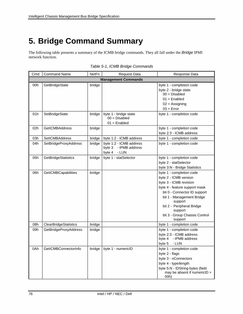
Intelligent Chassis Management Bus Bridge Specification
76 Intel / HP / NEC / Dell
5. Bridge Command Summary The following table presents a summary of the ICMB bridge commands. They all fall under the Bridge IPMI network function.
Table 5-1, ICMB Bridge Commands
Cmd Command Name NetFn Request Data Response Data Management Commands
00h GetBridgeState bridge byte 1 - completion code byte 2 - bridge state 00 = Disabled 01 = Enabled 02 = Assigning 03 = Error
01h SetBridgeState bridge byte 1 - bridge state 00 = Disabled 01 = Enabled
byte 1 - completion code
02h GetICMBAddress bridge byte 1 - completion code byte 2:3 - ICMB address
03h SetICMBAddress bridge byte 1:2 - ICMB address byte 1 - completion code 04h SetBridgeProxyAddress bridge byte 1:2 - ICMB address
byte 3 - IPMB address byte 4 - LUN
byte 1 - completion code
05h GetBridgeStatistics bridge byte 1 - statSelector byte 1 - completion code byte 2 - statSelector byte 3:N - Bridge Statistics
06h GetICMBCapabilities bridge byte 1 - completion code byte 2 - ICMB version byte 3 - ICMB revision byte 4 - feature support mask
bit 0 - Connector ID support bit 1 - Management Bridge
support bit 2 - Peripheral Bridge
support bit 3 - Group Chassis Control
support 08h ClearBridgeStatistics bridge byte 1 - completion code 09h GetBridgeProxyAddress bridge byte 1 - completion code
byte 2:3 - ICMB address byte 4 - IPMB address byte 5 - LUN
0Ah GetICMBConnectorInfo bridge byte 1 - numericID byte 1 - completion code byte 2 - flags byte 3 - nConnectors byte 4 - type/length byte 5:N - IDString bytes (field
may be absent if numericID = 00h)

Intelligent Chassis Management Bus Bridge Specification
Intel / HP / NEC / Dell 77
Cmd Command Name NetFn Request Data Response Data 0Bh GetICMBConnectionID bridge byte 1 - completion code
byte 2 - numericID byte 2 - typeLength byte 3:N - IDString
0Ch SendICMBConnectionID bridge byte 1:2 - ICMB address byte 1 - completion code 01h - illegal connector ID
byte 2 - rCompletion. byte 3 - numericID byte 4 - typeLength byte 5 - IDString
Discovery Commands 10h PrepareForDiscovery bridge byte 1 - completion code 11h GetAddresses bridge byte 1 - completion code
byte 2:N - List of discovered bridges
12h SetDiscovered bridge byte 1 - completion code 13h GetChassisDeviceId bridge byte 1 - completion code
byte 2 - Chassis Device ID 14h SetChassisDeviceId bridge byte 1 - Chassis Device ID byte 1 - completion code
Bridging Commands 20h BridgeRequest bridge byte 1:N - Data to be bridged to
next bus. See text byte 1 - completion code byte 2:M - Response from bridge request. See text.
21h BridgeMessage bridge byte 1:N - Data to be bridged to next bus. See text
byte 1 - completion code
22h DeviceBridgeRequest bridge byte 1:N - Data to be bridged to selected device. Note: this command is only accepted as an ICMB broadcast. See text.
byte 1 - completion code
Event Commands 30h GetEventCount bridge byte 1 - completion code
byte 2 - event count 31h SetEventDestination bridge byte 1:2 - ICMB address of
event destination bridge byte 1 - completion code
32h SetEventReceptionState bridge byte 1 - reception state 0 = Disabled 1 = Enabled byte 2 - eventSA byte 3 - LUN
byte 1 - completion code
33h SendICMBEventMessage bridge byte 1 - Event Code 0 = Online 1 = Attention (a.k.a. ‘Sensor’)
byte 1 - completion code
34h GetEventDestination (optional)
bridge byte 1 - completion code byte 2:3 - ICMB address of event
destination bridge

Intelligent Chassis Management Bus Bridge Specification
78 Intel / HP / NEC / Dell
Cmd Command Name NetFn Request Data Response Data 35h GetEventReceptionState
(optional) bridge byte 1 - completion code
byte 2 - reception state 00h = disabled 01h = enabled byte 3 - eventSA byte 4 - LUN
OEM Commands C0h - FEh
OEM Defined bridge byte 1 - completion code
0FFh Error Report (optional) bridge Returns reason for rejecting last silently discarded message, or in some cases, why an FFh (unspecified) completion code was returned. byte 1 - completion code byte 2 - Original command byte 3 - Error Code:
0 = Unknown 1 = Suspect Checksum 2 = Illegal Command 3 = Bad Length 4 = Bad Data Field 5 = Unrecognized netFn 6 = Invalid LUN 7 = Duplicated Request
[duplicate requests should always be responded to, if possible.]
8 = Node Busy C0h-FFh = OEM error codes

Intelligent Chassis Management Bus Bridge Specification
Intel / HP / NEC / Dell 79
6. Chassis Device Command Summary The following table presents a summary of the ICMB Chassis Device commands. They all fall under the Chassis IPMI network function.
Table 6-1, Chassis Device Command Summary
Cmd Command Name NetFn Request Data Response Data Chassis Device Commands
00h GetChassisCapabilities Chassis byte 1 - completion code byte 2 - Capabilities Flags bit 0 - Provides intrusion bit 1 - Provides Secure Mode bit 2 - Provides Diagnostic
Interrupt (FP NMI) bit 3 - Provides power
interlock byte 3 - Chassis FRU Info
Device Address byte 4 - Chassis SDR Device
Address byte 5 - Chassis SEL Device
Address byte 6 - Chassis SM Device
Address (byte 7) - Chassis Bridge Device
Address [See Section 3.5.1, Get Chassis Capabilities.]
01h GetChassisStatus Chassis
byte 1 - completion code byte 2 - Current Power State bit 0 - Power is on bit 1 - Power overload bit 2 - Interlock bit 3 - Power fault bit 4 - Power control fault bit 6:5 - Power restore policy byte 3 - Last Power Event bit 0 - AC fail bit 1 - Power overload bit 2 - Interlock bit 3 - Power fault bit 4 - Command on/off byte 4 - Misc Chassis State bit 0 - Intrusion bit 1 - Secure mode enabled bit 2 - Drive fault bit 3 - Cooling/fan fault

Intelligent Chassis Management Bus Bridge Specification
80 Intel / HP / NEC / Dell
Cmd Command Name NetFn Request Data Response Data 02h ChassisControl Chassis byte 1 - power command
00h : power off 01h : power on 02h : power cycle 03h : hard reset 04h : pulse Diagnostic
Interrupt (FP NMI) if supported
05h : ACPI soft shutdown trigger
byte 1 – completion code
03h ChassisReset Chassis byte 1 - completion code 04h ChassisIdentify Chassis byte 1 - completion code 05h SetChassisCapabilities
(optional) - see text on GetChassisCapabilities command.
Chassis byte 1 - Capabilities Flags bit 0 - Provides intrusion bit 1 - Provides Secure
Mode byte 2 - Chassis FRU Info
Device Address byte 3 - Chassis SDR Device
Address byte 4 - Chassis SEL Device
Address byte 5 - Chassis SM Device
Address (byte 6) - Chassis Bridge
Device Address [See Section 3.5.1, Get Chassis Capabilities.]
byte 1 - completion code

Intelligent Chassis Management Bus Bridge Specification
Intel / HP / NEC / Dell 81
Cmd Command Name NetFn Request Data Response Data 0Ah GroupChassisControl Chassis byte 1 – Control
bit 3:0 - operation 0h = power down 1h = power up 2h = power cycle (optional) 3h = hard reset 4h = pulse Diagnostic
Interrupt 5h = ACPI triggered soft-
shutdownbit bit 5:4 - operation delay control
00b = operation occurs immediately
01b = operation occurs after pre-configured delay
10b = cancel operation. 11b = reserved
bit 6 - reserved bit 7 - Request/Force
0b = request control operation.
1b = force control operation.
byte 2: Group ID 0 (1-based) 00h = unspecified FFh = all groups
byte 3: Member ID 0 (0-based) bit 3:0 - member ID bit 4 - 0b = perform member
ID check. 1b = skip member ID
check bit 7:5 - reserved
byte 4: Group ID 1 byte 5: Member ID 1
byte 6: Group ID 2 byte 7: Member ID 2 byte 8: Group ID 3 byte 9: Member ID 3
byte 1 - completion code [Note: The bridge does not
forward on responses on to ICMB if the request was received as a broadcasted request received from ICMB.]

Intelligent Chassis Management Bus Bridge Specification
82 Intel / HP / NEC / Dell
Cmd Command Name NetFn Request Data Response Data 0Bh SetGroupControlEnables Chassis Sets characteristics for given
group. byte 1 - Group entry selector
bit 7:4 - reserved bit 3:0 - Group entry selector
(0-based)
byte 2 - Group ID number 00h = unspecified
FFh = reserved byte 3 - operation enables (sets
which operations allowed under given group ID)
bit 7:6 - reserved bit 5 - 1b = enable soft shutdown
trigger bit 4 - 1b = enable diagnostic
interrupt bit 3 - 1b = enable hard reset bit 2 - 1b = enable power cycle bit 1 - 1b = enable power up bit 0 - 1b = enable power down
byte 4 - One or All selects (sets whether all members must request operation for it to be initiated, or just one or more members)
bit 7:6 - reserved bit 5 - 0b = soft shutdown, all 1b = soft shutdown, one bit 4 - 0b = diagnostic interrupt,
all 1b = diagnostic interrupt,
one bit 3 - 0b = hard reset, all 1b = hard reset, one bit 2 - 0b = power cycle, all 1b = power cycle, one bit 1 - 0b = power up, all 1b = power up, one bit 0 - 0b = power down, all 1b = power down, one
byte 5 - Operation delay time. In
seconds x 2. 1-based. 00h = no delay. byte 6:7 - Member control enables 15:0 = Member control enables
byte 1 - completion code

Intelligent Chassis Management Bus Bridge Specification
Intel / HP / NEC / Dell 83
Cmd Command Name NetFn Request Data Response Data 0Ch GetGroupControlEnables Chassis byte 1 - Group entry selector
bit 7:4 - reserved bit 3:0 - Group entry selector
(0-based)
byte 1 - completion Code byte 2 - Group entry selector bit 7:4 - reserved bit 3:0 - Group entry selector byte 3 - Group ID number byte 4 - operation enables (sets
which operations allowed under given group ID)
bit 7:6 - reserved bit 5 - 1b = soft shutdown trigger
enabled bit 4 - 1b = diagnostic interrupt
enabled bit 3 - 1b = hard reset enabled bit 2 - 1b = power cycle enabled bit 1 - 1b = power up enabled bit 0 - 1b = power down enabled
byte 5 - One or All selects bit 7:6 - reserved bit 5 - 0b = soft shutdown, all 1b = soft shutdown, one bit 4 - 0b = diagnostic interrupt, all 1b = diagnostic interrupt,
one bit 3 - 0b = hard reset, all 1b = hard reset, one bit 2 - 0b = power cycle, all 1b = power cycle, one bit 1 - 0b = power up, all 1b = power up, one bit 0 - 0b = power down, all 1b = power down, one
byte 6 - Operation delay time. In seconds x 2. 1-based.
00h = no delay. byte 7:8 - Group Membership Mask
(LSByte first) bit 15:0 = Member control enables.
A 1b in a bit position indicates control is enabled for corresponding member of the given group. Bit 0 corresponds to Member ID 0, bit 1 to ID 1, etc. [2]

Intelligent Chassis Management Bus Bridge Specification
84 Intel / HP / NEC / Dell
Cmd Command Name NetFn Request Data Response Data 0Dh GetGroupControlSettings Chassis byte 1 - reserved (write as 00h) byte 1 - completion code
Info for Group Entry 0 byte 2 - Operation enables byte 3 - Operation delay time byte 4:5 - Member control enables Info for Group Entry 1 byte 6 - Operation enables byte 7 - Operation delay time byte 8:9 - Member control enables Info for Group Entry 2 byte 10 - Operation enables byte 11 - Operation delay time byte 12:13 - Member control enables Info for Group Entry 3 byte 14 - Operation enables byte 15 - Operation delay time byte 16:17 - Member control enables

Intelligent Chassis Management Bus Bridge Specification
Intel / HP / NEC / Dell 85
Cmd Command Name NetFn Request Data Response Data 0Eh GetGroupControlStatus Chassis byte 1 - response selector
bit 3:0 - response selector 0h = by group. Controller looks
up whether given Group ID matches any of the enabled Group IDs, and if so, returns pending request data for that Group ID.
1h = by entry. Same as by group, but BMC looks up info by Entry number.
2h = by operation bit 7:4 - reserved
for response selector = “by group” byte 2 - Group ID number 00h = reserved for response selector = “by entry” byte 2 - Entry number
bit 3:0 - entry number 0h = Entry 1 1h = Entry 2 2h = Entry 3 3h = Entry 4 all other = reserved
bit 7:4 - reserved for response selector = “by operation” byte 2 - operation
bit 3:0 - operation 0h = power down 1h = power up 2h = power cycle 3h = hard reset 4h = Diagnostic Interrupt. 5h = soft-shutdown
bit 7:4 - reserved
byte 1 - completion code 80h = given group ID does not match
any of the enabled group IDs.
For response selector = “by group” or “by entry” byte 2 - Group ID or entry number,
based on whether selector is “by group” or “by entry”, respectively. Format matches corresponding field in request.
byte 3 - operation enables Request status byte 4 - 0 - 1b = requests pending for
other group IDs 0b = no requests pending
for other group IDs 7:1 - reserved Pending requests - Each bit = 1b indicates a pending request for the corresponding member ID within the given group. byte 5:6 - power down requests byte 7:8 - power cycle requests byte 9:10 - power up requests byte 11:12 - hard reset requests byte 13:14 - diagnostic interrupt
requests byte 15:16 - soft shutdown requests For response selector = “by operation” byte 2 - operation
bit 3:0 - operation 0h = power down 1h = power up 2h = power cycle 3h = hard reset 4h = Diagnostic Interrupt. 5h = soft-shutdown
bit 7:4 - reserved byte 3 - pending requests for specified operation
bit 0 - 1b = request pending for Entry 0
bit 1 - 1b = request pending for Entry 1
bit 2 - 1b = request pending for Entry 2
bit 3 - 1b = request pending for Entry 3
bit 7:4 - reserved
byte 4 - Group ID for Entry 0 byte 5 - Group ID for Entry 1 byte 6 - Group ID for Entry 2 byte 7 - Group ID for Entry 3

Intelligent Chassis Management Bus Bridge Specification
86 Intel / HP / NEC / Dell
Cmd Command Name NetFn Request Data Response Data 0FH GetPOHCounter Chassis see IPMI specification see IPMI specification
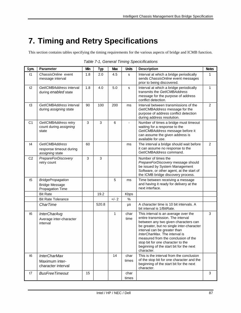
Intelligent Chassis Management Bus Bridge Specification
Intel / HP / NEC / Dell 87
7. Timing and Retry Specifications This section contains tables specifying the timing requirements for the various aspects of bridge and ICMB function.
Table 7-1, General Timing Specicifications
Sym. Parameter Min Typ Max Units Description Notes t1 ChassisOnline event
message interval 1.8 2.0 4.5 s Interval at which a bridge periodically
sends ChassisOnline event messages prior to being discovered.
1
t2 GetICMBAddress interval during enabled state
1.8 4.0 5.0 s Interval at which a bridge periodically transmits the GetICMBAddress message for the purpose of address conflict detection.
1
t3 GetICMBAddress interval during assigning state
90 100 200 ms Interval between transmissions of the GetICMBAddress message for the purpose of address conflict detection during address resolution.
2
C1 GetICMBAddress retry count during assigning state
3 3 6 - Number of times a bridge must timeout waiting for a response to the GetICMBAddress message before it can assume the given address is available for use.
t4 GetICMBAddress response timeout during assigning state
60 ms The interval a bridge should wait before it can assume no response to the GetICMBAddress command.
2
C2 PrepareForDiscovery retry count
3 3 Number of times the PrepareForDiscovery message should be issued by System Management Software, or other agent, at the start of the ICMB bridge discovery process.
t5 BridgePropagation Bridge Message Propagation Time
5 ms Time between receiving a message and having it ready for delivery at the next interface.
Bit Rate 19.2 Kbps Bit Rate Tolerance +/- 2 % CharTime 520.8 µs A character time is 10 bit intervals. A
bit interval is 1/BitRate.
t6 InterCharAvg Average inter-character interval
1 char time
This interval is an average over the entire transmission. The interval between any two given characters can be greater, but no single inter-character interval can be greater than InterCharMax. The interval is measured from the conclusion of the stop bit for one character to the beginning of the start bit for the next character.
3
t6 InterCharMax Maximum inter-character interval
14 char times
This is the interval from the conclusion of the stop bit for one character and the beginning of the start bit for the next character.
t7 BusFreeTimeout 15 char times
3

Intelligent Chassis Management Bus Bridge Specification
88 Intel / HP / NEC / Dell
Notes: 1. This specification may be temporarily violated during initialization / re-initialization of the bridge. 2. This interval excludes time required to win bus arbitration. 3. One character time (char time) is equivalent to 10 bits transmitted at the specified bit rate. The character time
tolerance is the same as the bit rate tolerance.
Table 7-2, Arbitration Timing Specifications
Sym. Parameter Min Typ Max Units Description Notes XcvrOffDelay 60 µs ArbDelay 90 µs ArbSample 10 µs Interval for sampling state changes
during arbitration.
ArbStartWindow 10 µs Time between sampling bus high and driving the arbitration pulse low.
ArbPulseIncrement 30 µs ArbPulseTolerance +/-10 µs ArbPulseWidth 30 210 µs The arbitration pulse width varies from
min to max in increments of ArbPulseIncrement, with an overall tolerance of ArbPulseTolerance.
ArbPulseStart 0 450 µs The arbitration pulse width varies from min to max in increments of ArbPulseIncrement, with an overall tolerance of ArbPulseTolerance.
PreCharge 12 16 20 µs The PreCharge interval follows the arbitration pulse. The bridge drives its output high to speed the signal transition from the low to high state.
PktStartMin 1 1 2 char time
The UART in some implementations may see the arbitration pulse as a start pulse. This delay is to ensure the Start Character is not corrupted by the transition.
ArbLoss 0 10 µs A low detected anywhere in this interval indicates a loss of arbitration. The interval begins following the PreCharge pulse.

Intelligent Chassis Management Bus Bridge Specification
Intel / HP / NEC / Dell 89
8. Electrical Specifications The ICMB is specified to be used with “1/4 load” or better TIA/EIA RS-485 transceivers. A 1/8th load transceiver, such as the Linear Technology Corporation LTC1487, is preferred. TIA/EIA RS-485 parallel termination is not used. Instead, a series termination is used. This is done to avoid the need for having termination resistors placed at the ends of the cable.
The bus is specified to electrically support up to 64 chassis on a given ICMB bus.
All electrical characteristics of the transceivers are 1/4 load TIA/EIA RS-485 compatible, measured at the connector, unless otherwise specified.
SYMBOL PARAMETER MIN TYP MAX UNITS - Loading 1/4 TIA/EIA RS-485 Unit Load
IOSD1 Driver short-circuit current, Vout = HIGH
35 mA
IOSD2 Driver short-circuit current, Vout = LOW
35 mA
8.1 Optional Current Limit External circuitry can be used to limit the supply current draw from standby 5V power. The transceiver must still be able to meet the minimum driver short-circuit current specifications listed above. The transceivers themselves shall have intrinsic short-circuit protection such that the device will not be damaged by an indefinite short across the outputs.
8.2 Failsafe Level The transceiver is required to have a failsafe feature that guarantees a logic-high output if the input is open circuit.
8.3 Common Mode Choke An optional Common Mode Choke can be utilized to reduce high-frequency electromagnetic interference. The selection of the device is implementation-specific. The effect of the choke should be negligible on differential signals over a 0Hz to ~200 kHz range.
8.4 Series Termination The ICMB uses series termination to reduce the effect of signal reflections on the cable. Resistor values should be selected such that the output impedance of the driver in series with the termination resistors matches the cable impedance.
8.5 ICMB Transceiver Connections Figure 8-1, Example ICMB Transceiver Circuit, shows an example of an ICMB transceiver circuit for an ICMB connection that does not incorporate the optional connector ID signals. The following section presents an example illustrating transceiver connections for the Connector ID signals.

Intelligent Chassis Management Bus Bridge Specification
90 Intel / HP / NEC / Dell
Note that the listed components are examples only. It is the responsibility of the designer to create the ICMB transceiver circuitry that meets the electrical specifications plus any additional product or agency requirements, such as electromagnetic interference specifications.
Figure 8-1, Example ICMB Transceiver Circuit
Microe.g.
87C652
Int0
Rxd
Txd
P3.5
RS485 Transe.g. LTC1487
22
22
22
22
22pf22pf
22pf
Rcv En
Xmit En
Xmit
RcvConn.Molex15-83-0906
3
4
1
Current Limit
5v
83
4
1
2
6
7
Vcc
1k
A
B
Rx/Tx+
Rx/Tx-Choke
e.g.PE-
67531
DI
DO
8.6 Connector ID Interconnect Example Figure 8-2, Example Connector ID Signal Connections, illustrates an example ICMB configuration using the Connector ID signal option. The figure shows three chassis connectors. The ICMB connection is bussed between the connectors and goes to a single RS-485 transceiver while each Connector ID signal is routed to a separate RS-485 transceiver in the chassis. To simplify the figure, the ICMB and Connector ID signals are just shown using singles line rather showing both signals of the differential signal pair.

Intelligent Chassis Management Bus Bridge Specification
Intel / HP / NEC / Dell 91
Figure 8-2, Example Connector ID Signal Connections
Microcontroller
Vcc
GP_IN A
Con
nect
or ID
A
ICM
B
ICM
B
ICM
B
Con
nect
or ID
B
Con
nect
or ID
C
UARTRx
UARTTx /
ARB_OUT
ARB_IN GP_IN B GP_IN CICMB_EN ID_DRV_EN
Connector BConnector A Connector C
Filters/Termination
Filters/Termination
Filters/Termination
The Connector ID signal is normally ‘1’ when the signal is idle and is driven active ‘0’. As inputs, the Connector ID signals must be monitored individually; therefore they’re shown routed to individual general-purpose input pins on the management controller in this example.
As outputs, the Connector ID signals are either driven to ‘0’, ‘1’, or placed into the high-impedance state simultaneously. The Connector ID signal needs to be briefly driven to ‘1’ to speed up the 0-to-1 transition when returning the signal to the ‘idle’ (High-impedance) state. Thus, two signals are required. One to control the polarity of the output and the other to control whether the output is driven or not.
Note that an actual implementation will take into account things like the default state of the microcontroller output pins. For example, if the output pins in the figure went high as the default state the transceivers would come up enabled. This would likely cause problems with the bus during the microcontroller’s initialization.
8.7 Cable ICMB cables can be routed between systems in a daisy-chained, passive star, or multiple ‘T’ arrangement. There are no additional requirements on stub-lengths or lengths of segments between chassis.
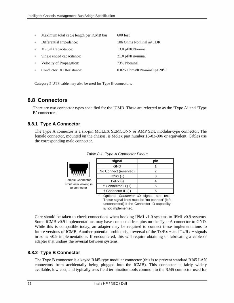
Intelligent Chassis Management Bus Bridge Specification
92 Intel / HP / NEC / Dell
• Maximum total cable length per ICMB bus: 600 feet
• Differential Impedance: 106 Ohms Nominal @ TDR
• Mutual Capacitance: 13.0 pF/ft Nominal
• Single ended capacitance: 21.0 pF/ft nominal
• Velocity of Propagation: 73% Nominal
• Conductor DC Resistance: 0.025 Ohms/ft Nominal @ 20°C
Category 5 UTP cable may also be used for Type B connectors.
8.8 Connectors There are two connector types specified for the ICMB. These are referred to as the ‘Type A’ and ‘Type B’ connectors.
8.8.1 Type A Connector The Type A connector is a six-pin MOLEX SEMCONN or AMP SDL modular-type connector. The female connector, mounted on the chassis, is Molex part number 15-83-906 or equivalent. Cables use the corresponding male connector.
Table 8-1, Type A Connector Pinout
signal pin GND 1
No Connect (reserved) 2 Tx/Rx (+) 3 Tx/Rx (-) 4
† Connector ID (+) 5
123456 Female Connector,
Front view looking in to connector
† Connector ID (-) 6 † Optional Connector ID signal, see text.
These signal lines must be ‘no-connect’ (left unconnected) if the Connector ID capability is not implemented.
Care should be taken to check connections when hooking IPMI v1.0 systems to IPMI v0.9 systems. Some ICMB v0.9 implementations may have connected free pins on the Type A connector to GND. While this is compatible today, an adapter may be required to connect these implementations to future versions of ICMB. Another potential problem is a reversal of the Tx/Rx + and Tx/Rx − signals in some v0.9 implementations. If encountered, this will require obtaining or fabricating a cable or adapter that undoes the reversal between systems.
8.8.2 Type B Connector The Type B connector is a keyed RJ45-type modular connector (this is to prevent standard RJ45 LAN connectors from accidentally being plugged into the ICMB). This connector is fairly widely available, low cost, and typically uses field termination tools common to the RJ45 connector used for

Intelligent Chassis Management Bus Bridge Specification
Intel / HP / NEC / Dell 93
10 and 100 Mbps twisted-pair Ethernet. The cable plug is AMP part number 5-554743-3 or equivalent. A corresponding jack (socket) is used for the chassis.
Table 8-2, Type B Connector Pinout
signal pin Tx/Rx (+) 1 Tx/Rx (-) 2
GND 3 † Connector ID (+) 4
GND 5 † Connector ID (-) 6
No Connect (reserved) 7
No Connect (reserved) 8 † Optional Connector ID Signal, see text. Signal line
should be a ‘no-connect’ (nc) if Connector ID capability is not implemented.

Intelligent Chassis Management Bus Bridge Specification
94 Intel / HP / NEC / Dell
Appendix A. Bridging Operation - A ‘Memo’ Analogy It may be useful to use one of those old ‘memo’ analogies to explain how bridging works. Suppose there are four offices: A, B, C, and D. Each office in sequence is connected with a door, i.e. there is a door between A and B, B and C, and between C and D.
Office A formats a request I’m in office ‘A’ and I’m curious about the worker in office D. ‘Seems I haven’t heard anything from him in a while. So I grab a sheet of memo paper and format a status request message. It say’s “How’s it going?”.
A sends to B I have a notepad and record the following before I send the envelope:
Request Letter 1, via office B. Request was “How’s it going?”
This is my personal record that I sent a particular memo and I am expecting a response. I put the memo in an envelope, and address it:
To: office D
I then put that envelope in another envelope, and address it:
To: office C
I then put that in yet another envelope and address it:
To: office B - Request 1. From: office A.
I then slide the envelope under the door to office B.
B sends to C The worker in office B opens the outer envelope and removes the contents, finding an envelope labeled:
To: office C
The worker in office B has a notepad and writes down:
Request Letter 1 from office A, forwarded to office C as Request Letter 219.
The worker adds:
- Request 219. From: office B
to the address on the envelope. Worker B uses the added number so when a response comes back, they can look up who to forward the response on to. Worker B then pushes the envelope under the door to office C.
C to D The worker in office C receives envelope and opens it, only to find another envelope labeled:
To: office D

Intelligent Chassis Management Bus Bridge Specification
Intel / HP / NEC / Dell 95
The worker writes down on their notepad:
Request Letter 219 from office B, forwarded to office D as Request Letter 55.
The worker adds:
- Request 55. From: office D
This is how Worker C remembers who to forward the response back to. Worker D then pushes the envelope under the door to office D.
D responds to C The worker in office D receives the envelope and writes down on their notepad:
Request Letter 55 from office D
The memo is taken out and read. It says “How’s it going?”. The worker in office D wonders why the worker in office C is wants to know how things are going, but responds anyway. The worker in office D takes out a fresh memo sheet and writes down “OK”. This is then put in a fresh envelope and labeled:
To: office C - Response 55. From: office D
and pushed back under the door to office C.
C responds to B The worker in office C receives the envelope and checks his notepad to see who “Request Letter 55 to office D” was originally from. The notepad lists this as having come from office B as Request Letter 219. So the worker takes the memo out of the envelope, places it in a new one, and labels it:
To: office B - Response 219. From: office D, via office C
This is then pushed through the slot in the door to office B.
B responds to A The worker in office B receives the tube and checks their notepad to see who “Request Letter 219 to office C” was originally from. The notepad lists this as having come from office A as Request Letter 1. So the worker takes the memo out of the envelope, places it in a new one, and labels the envelope:
To: office A - Response 1. From: office D, via office C, via office B
This is then slid under the door to office A.
Office A handles response I receive an envelope. It’s labeled:
To: office A - Response Letter 1. From: office D, via office C, via office B
I check my notepad for request messages that I’ve sent to via office B and see that this should be a response to my request message 1 ‘How’s it going?’ to office D beyond office C. I then open the envelope and find the reply “OK”.
I’m reassured to find that the worker in office D is all right.

Intelligent Chassis Management Bus Bridge Specification
96 Intel / HP / NEC / Dell
LAST PAGE