iport.reference.programmable logic controller...the iport programmable logic controller (plc) is a...
TRANSCRIPT

Programmable Logic ControllerReference Guide


...the industry’s richest feature set
LookupTable
SignalRoutingBlock
I0
I1
I2
I3
I4
I5
I7
from
IO c
able
from
vide
oca
ble
toIO
cab
leto
vide
oca
ble
ImageControlBlock
IO Block
Video IOBlock
Video IOBlock
IO Block
Enhanced FunctionBlock
PLC
I6
RemoteControlBlockfro
mho
st P
C
Q3Rescaler
inbackup
Pulse Generator 1pg1_out
rsl_out
A1
Q6
fromencoder
(120 DPIor
700 DPI)
to cameratrigger(300 DPI)
Rescaling a conveyor belt’s encoder signal to capture exactly 300 DPI with a line-scan camera (page 70)

These products are not intended for use in life support appliances, devices, or systems where malfunction of these products can reasonably be expected to result in personal injury. Pleora Technologies Inc. (Pleora) customers using or selling these products for use in such applica-tions do so at their own risk and agree to indemnify Pleora for any damages resulting from such improper use or sale.
Copyright © 2008 Pleora Technologies Inc. All information provided in this manual is believed to be accurate and reliable. No responsibility is assumed by Pleora for its use. Pleora reserves the right to make changes to this information without notice. Redistribution of this manual in whole or in part, by any means, is prohibited without obtaining prior permission from Pleora. 2/25/08
Version 2.4

Contents
About.............................................................................................................................. 7Understanding the PLC ................................................................................................ 9
Understanding the PLC workflow .................................................................................................................. 9Understanding the PLC wiring ..................................................................................................................... 10Understanding the diagrams .......................................................................................................................... 11Understanding the PLC icons ....................................................................................................................... 12What now? .................................................................................................................................................... 12
Demonstrating the PLC in 10 minutes ...................................................................... 13Monitoring your PLC signals with LED indicator ....................................................................................... 13Monitoring your PLC signals with a feedback loop ..................................................................................... 15Demonstrating the Remote Control Block.................................................................................................... 16Demonstrating the Lookup Table.................................................................................................................. 16Demonstrating the Pulse Generator (Periodic) ............................................................................................. 17Demonstrating the Pulse Generator (Triggered)........................................................................................... 18Demonstrating the Delayer ........................................................................................................................... 19Demonstrating the Rescaler .......................................................................................................................... 20Demonstrating the Rescaler (with backup)................................................................................................... 21Demonstrating the General Purpose Counter ............................................................................................... 23Demonstrating the Interrupt FIFO ................................................................................................................ 24
Configuring the PLC with the iPORT Vision Suite ................................................... 27Configuring the PLC with the SDK.............................................................................................................. 27Configuring the PLC with Coyote ................................................................................................................ 27
Configuring the PLC with the iPORT PureGEV Suite .............................................. 31IO Block........................................................................................................................................................ 31Video IO Block ............................................................................................................................................. 31Remote Control Block .................................................................................................................................. 32Signal Routing Block.................................................................................................................................... 32Lookup Table ................................................................................................................................................ 32Enhanced Function Block............................................................................................................................. 33Special PLC settings ..................................................................................................................................... 37
IO Block........................................................................................................................ 39Monitoring the state of the IO Block ............................................................................................................ 40Synchronization Block.................................................................................................................................. 40Input Debouncing Block............................................................................................................................... 41TTL Input Block ........................................................................................................................................... 42TTL Output Block ........................................................................................................................................ 43LVDS Input Block ........................................................................................................................................ 43Optically Isolated Input Block ...................................................................................................................... 44Optically Isolated Output Block ................................................................................................................... 45
Video IO Block ............................................................................................................. 47How the Video IO Block works.................................................................................................................... 47Video IO Block (for Camera Link imaging data) ......................................................................................... 48Video IO Block (for analog video) ............................................................................................................... 48Video IO Block (for LVDS imaging data) .................................................................................................... 49
Remote Control Block................................................................................................. 51

Signal Routing Block .................................................................................................. 53How the Signal Routing Block works .......................................................................................................... 53
Lookup Table ............................................................................................................... 55How the Lookup Table works....................................................................................................................... 56
Enhanced Function Block .......................................................................................... 57Overview of the Enhanced Function Block .................................................................................................. 58Pulse Generator............................................................................................................................................. 59Rescaler......................................................................................................................................................... 60Delayer.......................................................................................................................................................... 61General Purpose Counter .............................................................................................................................. 62Interrupt FIFO............................................................................................................................................... 64Counter Trigger Generator............................................................................................................................ 64Timestamp Counter....................................................................................................................................... 65
Image Control Block ................................................................................................... 67Real world samples..................................................................................................... 69
Triggering an area-scan camera with a presence detector ............................................................................ 69Acquiring a 300 DPI image with a line-scan camera ................................................................................... 70
Glossary of signal names........................................................................................... 73The PLC at a glance .................................................................................................... 75
Programmable Logic Controller ................................................................................................................... 75Enhanced Function Block............................................................................................................................. 76PLC and Enhanced Function Block (on one page)....................................................................................... 77

7
About
The iPORT™ Programmable Logic Controller (PLC) is a powerful tool that lets you control external machines, react to inputs, and create a machine vision system. By controlling your system using the PLC, you can make functional changes, adjust timing, or add features without having to add any new hardware.
Don’t read this book straight through!To learn the PLC effectively (and hands on), we recommend starting with “Understanding the PLC” on page 9, followed by “Demonstrating the PLC in 10 minutes” on page 13. Each demonstration highlights a particular aspect of the PLC, and includes links to relevant sections in this guide. Once you finish the demonstrations, you’ll have a solid foundation for creating your own powerful, customized system.
Using the PLC with Coyote, the iPORT Vision Suite SDK, and the iPORT PureGEV SuiteThe iPORT Programmable Logic Controller Reference Guide is written as generally as possible and the high-level concepts are always identical for all IP Engines. Specific names, directions, and screenshots are taken from iPORT Coyote.
The PLC features map one-to-one with the iPORT Vision Suite SDK; for the list of parameters, see “CyDeviceExtensionConstants.h” in the iPORT C++ SDK Reference Guide.
For GEV-enabled IP Engines, the PLC can vary dramatically, depending how it’s been configured (AutoGEV lets can hide or remap features). However, by default, the features are very similar. To convert the Coyote-centric names for your GEV-enabled IP Engine, use the tables in “Configuring the PLC with the iPORT PureGEV Suite” on page 31.
Copyright © 2008 Pleora Technologies Inc.

8 About
Copyright © 2008 Pleora Technologies Inc.

9
Understanding the PLC
Once you understand the overall concept of how the PLC works, programming the PLC will quickly become natural to you.
In this section:Understanding the diagrams .......................................................................................11Understanding the PLC wiring .................................................................................. 10Understanding the PLC icons .................................................................................... 12What now? ................................................................................................................. 12
Understanding the PLC workflowIn general, you route signals from the inputs on the left to the Enhanced Function Block. The Enhanced Function Block has many features that let you manipulate your signals.
LookupTable
SignalRoutingBlock
I0
I1
I2
I3
I4
I5
I7
from
IO c
able
from
vide
oca
ble
toIO
cab
leto
vide
oca
ble
ImageControlBlock
IO Block
Video IOBlock
Video IOBlock
IO Block
Enhanced FunctionBlock
PLC
I6
RemoteControlBlockfro
mho
st P
C
Copyright © 2008 Pleora Technologies Inc.

10 Understanding the PLC
Once you manipulate your signal, you can route it to the outputs on the right. However, you must route the signal back through the Signal Routing Block and the Lookup Table.
If you’re not finished processing the signal, you can route it back to the Enhanced Function Block again.
Understanding the PLC wiringThe wiring within the PLC is fixed; you control what happens in the gray blocks.
LookupTable
SignalRoutingBlock
I0
I1
I2
I3
I4
I5
I7
from
IO c
able
from
vide
oca
ble
toIO
cab
leto
vide
oca
ble
ImageControlBlock
IO Block
Video IOBlock
Video IOBlock
IO Block
Enhanced FunctionBlock
PLC
I6
RemoteControlBlockfro
mho
st P
C
LookupTable
SignalRoutingBlock
I0
I1
I2
I3
I4
I5
I7
from
IO c
able
from
vide
oca
ble
toIO
cab
leto
vide
oca
ble
ImageControlBlock
IO Block
Video IOBlock
Video IOBlock
IO Block
Enhanced FunctionBlock
PLC
I6
RemoteControlBlockfro
mho
st P
C
Copyright © 2008 Pleora Technologies Inc.

11
By reconfiguring the gray blocks, you can manipulate and reroute signals. The sample below is a counter taken from “Demonstrating the General Purpose Counter” on page 23. For clarity, the unused wiring isn’t shown.
Understanding the diagramsThe PLC diagram includes a simplified version of the Enhanced Function Block.
For easier reference, you can find large versions of both diagrams in the back of this guide. See “The PLC at a glance” on page 75.
LookupTable
SignalRoutingBlock
I0
I1
I2
I3
I4
I5
I7
from
IO c
able
from
vide
oca
ble
toIO
cab
leto
vide
oca
ble
ImageControlBlock
IO Block
Video IOBlock
Video IOBlock
IO Block
Enhanced FunctionBlock
PLC
I6
RemoteControlBlockfro
mho
st P
C
Q3Q16Q17 gp_cnt_gt
Q0
General PurposeCounter
cleardownup
PLC_ctrl0PLC_ctrl1PLC_ctrl2
Copyright © 2008 Pleora Technologies Inc.

12 Understanding the PLC
Understanding the PLC iconsTo help you distinguish blocks from each other, each one features an icon that provides a distinct visual cue and suggests its function. You can find the icon at the bottom of every block.
IO BlockThe IO Block lets you communicate between the PLC and the “outside world” through the IP Engine’s 12-pin IO connector. See “IO Block” on page 39.
Video IO BlockThe Video IO Block lets you communicate between the PLC and the camera through the IP Engine’s video connector. The block receives a video signal and provides the PLC with discrete frame valid (FVAL), line valid (LVAL), and similar signals. Some cameras let you send control signals back to the camera. See “Video IO Block” on page 47.
Remote Control BlockThe Remote Control Block lets you send inputs from your host PC to the PLC. The PLC control bits let you simulate inputs and test your configuration without having to connect external components to your IP Engine. You can use the Remote Control Block to simulate inputs from your encoders, cameras, presence detectors, and other components. Once you’re confident that your system works (at your desk), you can cable everything together, change a few configurations, and test your finished design (on site). You can also control this block from the iPORT SDK. See “Remote Control Block” on page 51.
Signal Routing BlockIn its simplest terms, the Signal Routing Block is a group of switches that let you route signals to the Lookup Table (described next). See “Signal Routing Block” on page 53.
Lookup TableThe Lookup Table lets you route signals within the PLC, as well as your signals using simple or complex Boolean expressions. Using the Signal Routing Block and the Lookup Table, you can route signals from almost anywhere to almost anywhere. See “Lookup Table” on page 55.
Enhanced Function BlockThe Enhanced Function Block lets you perform complex functions on your signals. You can delay a signal, generate a pulsed signal, count pulses, generate interrupts to the PC, and more. See “Enhanced Function Block” on page 57.
Image Control BlockThe Image Control Block lets you configure the image LVAL, FVAL, and TRIG signals used by the IP Engine’s image grabber. You can use the signals exactly as they come from the camera or you can manipulate them to create your own signal. This block is especially important if you’re acquiring images using a line-scan camera. See “Image Control Block” on page 67.
What now?Now that you’ve seen an overview of the PLC, we recommend that you follow the fun demonstrations; see “Demonstrating the PLC in 10 minutes” on page 13. From there, you can read the rest of this guide as you require (to get precise details about how various blocks work).
Copyright © 2008 Pleora Technologies Inc.

13
Demonstrating the PLC in 10 minutes
The following demonstrations let you learn how the PLC works using brief tutorials. Each demonstra-tion shows a particular feature in the PLC and builds on the previous demonstration. Running through all of them will give you a good understanding of how to use the PLC.
Once you’ve set up your system, the demonstrations really will take under 10 minutes each but for better understanding, consider reading the background for each demonstration.
The demonstrations use an LED indicator that lets you see the results of your configurations. Though the PLC is lightning fast, the demonstrations use low frequency signals that can be seen with the human eye (and shown with a regular LED).
To run a demonstration:1. Attach an output indicator to your IP Engine. We recommend the LED indicator described in
“Monitoring your PLC signals with LED indicator” on page 13. However, you can also use the feedback loop described in “Monitoring your PLC signals with a feedback loop” on page 15.
2. Cable your IP Engine to your PC and connect to it using Coyote. See the iPORT Quick Start Guide.3. Follow the procedure for a demonstration. We recommend doing them in order, starting from
“Demonstrating the Remote Control Block” on page 16. To configure the PLC or use the PLC control bits, see “Configuring the PLC with the iPORT Vision Suite” on page 27.
4. Continue trying demonstrations.Have fun and feel free to experiment on your own!
In this section:Monitoring your PLC signals with LED indicator .................................................... 13Monitoring your PLC signals with a feedback loop .................................................. 15Demonstrating the Remote Control Block................................................................. 16Demonstrating the Lookup Table............................................................................... 16Demonstrating the Pulse Generator (Periodic) .......................................................... 17Demonstrating the Pulse Generator (Triggered)........................................................ 18Demonstrating the Delayer ........................................................................................ 19Demonstrating the Rescaler ....................................................................................... 20Demonstrating the Rescaler (with backup)................................................................ 21Demonstrating the Interrupt FIFO ............................................................................. 24
Monitoring your PLC signals with LED indicatorBackground information: see “IO Block” on page 39.
When you’re configuring the PLC, having an output indicator lets you confirm that the outputs you generate in the PLC are correct (and actually happening). Output indicators also give you the tools you
Copyright © 2008 Pleora Technologies Inc.

14 Demonstrating the PLC in 10 minutes
need to test your setup, find problems, and experiment with the powerful features in the Enhanced Function Block.
The LED indicator turns on when the TTL_OUT0 is high. In general, the LED will typically let you see frequencies up about 30 Hz, after which the LED will appear to be continuously set at a particular intensity. (This is a function of the human eye’s ability to register changes.)
NOTE! Improper insertion of the wires may cause mechanical damage. For a better connection with a lower risk of electrical or mechanical damage to the IP Engine, solder your circuit to a Hirose mating connector.
NOTE! Incorrect wiring or accidentally shorting a connection to chassis ground can damage the IP Engine. Always disconnect the IP Engine’s power before making connections and confirm the circuit before using it.
NOTE! The pinouts vary by IP Engine model. Consult your hardware guide to confirm the pinouts for your particular model.
To create an LED indicator:1. Inspect your iPORT IP Engine for the model number (e.g. PT1000-CL4, etc.)2. Consult the corresponding hardware guide.3. In the hardware guide, note the IO pinouts for TTL_OUT0 and TTL_IN0.4. Turn off the IP Engine.5. Connect the LED and resistor to the TTL_OUT0 and the GND pins. The resistance value is a
suggestion; ensure the value you use is appropriate for your LED and doesn’t exceed the rated output current for the IP Engine’s TTL_OUT0 signal.
6. Confirm the circuit is correct.
To view activity on TTL_OUT0:• Watch for the LED to turn on, turn off, or flicker. Fast signals may produce a very faint light or
seem to be continuously on, so you may have to interpret the result.
LookupTable
SignalRoutingBlock
I0
I1
I2
I3
I4
I5
I7
from
IO c
able
from
vide
oca
ble
toIO
cab
leto
vide
oca
ble
ImageControlBlock
IO Block
Video IOBlock
Video IOBlock
IO Block
Enhanced FunctionBlock
PLC
I6
RemoteControlBlockfro
mho
st P
C
Q0
1k
Copyright © 2008 Pleora Technologies Inc.

15
Monitoring your PLC signals with a feedback loopBackground information: see “IO Block” on page 39.
A feedback loop lets you reroute an output signal back into the PLC. You can monitor the signals using Coyote.
The feedback loop sends the TTL_OUT0 signal back into the PLC where you can see it using the PLC Control Bits dialog. Though the PLC control bits are accurate within the IP Engine, Coyote only samples the values roughly every 200 ms. Thus, you may be able to see frequencies up to 2-2.5 Hz, and should consistently see state changes on a signals 1 Hz or slower.
Consider using the LED indicator instead. Though the feedback loop is slightly easier to implement, the LED indicator shows state changes more accurately (and is more fun). See “Monitoring your PLC signals with LED indicator” on page 13.
For precise monitoring, connect your IP Engine’s TTL_OUT0 signal to an oscilloscope.
(Also see the notes in “Monitoring your PLC signals with LED indicator” on page 13.)
To create a feedback loop:1. Inspect your iPORT IP Engine for the model number (e.g. PT1000-CL4, etc.)2. Consult the corresponding hardware guide.3. In the hardware guide, note the IO pinouts for TTL_OUT0 and TTL_IN0.4. Cut a ~75 mm [3”] piece of 24 AWG solid core wire. Strip 5 mm [1/4”] of insulation from each
end.
NOTE! For a more reliable feedback loop, solder a IO connector that cables (shorts) the TTL_OUT0 and TTL_IN0 pins together.
5. Turn off the IP Engine.6. Using the wire, connect TTL_OUT0 and TTL_IN0.
LookupTable
SignalRoutingBlock
I0
I1
I2
I3
I4
I5
I7
from
IO c
able
from
vide
oca
ble
toIO
cab
leto
vide
oca
ble
ImageControlBlock
IO Block
Video IOBlock
Video IOBlock
IO Block
Enhanced FunctionBlock
PLC
I6
RemoteControlBlockfro
mho
st P
C
Q0A0
Feedback wire
TTL_OUT0TTL_IN0
Copyright © 2008 Pleora Technologies Inc.

16 Demonstrating the PLC in 10 minutes
7. Confirm that the circuit is correct.
To view activity on TTL_OUT0:• See “Monitoring the IO Block” on page 27.
Demonstrating the Remote Control BlockBackground information: see “Remote Control Block” on page 51.
This demonstration lets you directly control the state of the output by making changes to PLC_ctrl0. You can watch the output change with each mouse click.
Procedure1. Create an output indicator. See “Monitoring your PLC signals with LED indicator” on page 13.2. In the IP Engine tab, make the following configurations and click Apply.
Signal Routing BlockI0: PLC Control Bit 0
Lookup TableQ0=I0
3. Control the circuit using PLC_ctrl0.
ResultsWhen you set PLC_ctrl0 to true, the output is true. When you set it to false, the output is false.
Demonstrating the Lookup TableBackground information: see “Lookup Table” on page 55.
This demonstration uses the Lookup Table to perform Boolean operations on your inputs.
Your inputs PLC_ctrl0, PLC_ctrl1, and PLC_ctrl1 are output as a single signal after the following operation:
Procedure1. Create an output indicator. See “Monitoring your PLC signals with LED indicator” on page 13.
LookupTable
SignalRoutingBlock
I0
I1
I2
I3
I4
I5
I7
from
IO c
able
from
vide
oca
ble
toIO
cab
leto
vide
oca
ble
ImageControlBlock
IO Block
Video IOBlock
Video IOBlock
IO Block
Enhanced FunctionBlock
PLC
I6
RemoteControlBlockfro
mho
st P
C
Q0
PLC_ctrl0
output PLCCTRL0 PLCCTRL1∩( ) PLCCTRL2∪=
Copyright © 2008 Pleora Technologies Inc.

17
2. In the IP Engine tab, make the following configurations and click Apply.
Lookup Table:Q0=(I0&I1)|I4
Signal Routing Block:I0: PLC Control Bit 0I1: PLC Control Bit 1I4: PLC Control Bit 2
3. Control the circuit using PLC_ctrl0, PLC_ctrl1, and PLC_ctrl2.
ResultsWhen you set PLC_ctrl2 to true, the output is true. The output is also true if you set both PLC_ctrl0 and PLC_ctrl1 to true.
Demonstrating the Pulse Generator (Periodic)Background information: See “Overview of the Enhanced Function Block” on page 58 and “Pulse Generator” on page 59.
This demonstration uses a Pulse Generator to output a continuous 1 Hz pulse that is high for 0.25 s and low for 0.75 s.
Procedure1. Create an output indicator. See “Monitoring your PLC signals with LED indicator” on page 13.
LookupTable
SignalRoutingBlock
I0
I1
I2
I3
I4
I5
I7fro
mIO
cab
le
from
vide
oca
ble
toIO
cab
leto
vide
oca
ble
ImageControlBlock
IO Block
Video IOBlock
Video IOBlock
IO Block
Enhanced FunctionBlock
PLC
I6
RemoteControlBlockfro
mho
st P
C
Q0
PLC_ctrl0PLC_ctrl1PLC_ctrl2
Copyright © 2008 Pleora Technologies Inc.

18 Demonstrating the PLC in 10 minutes
2. In the IP Engine tab, make the following configurations and click Apply.
Pulse Generator 0Width (high): 1000Delay (low): 3000Granularity factor: 8320Emit periodic pulse: TrueTrigger mode: NAPulse frequency: ~1 Hz (read only)
Signal Routing BlockI0: Pulse Generator 0 Output
Lookup Table: Q0=I0
ResultsThe PLC outputs a steady 1 Hz signal with a 25% duty cycle.
Demonstrating the Pulse Generator (Triggered)Background information: see “Pulse Generator” on page 59.
This demonstration uses a Pulse Generator to emit a single pulse at your command. The pulse is low for 1 s and high for 1 s. The pulse starts with the low, so you can incorporate a built-in delay, if you like.
Procedure1. Create an output indicator. See “Monitoring your PLC signals with LED indicator” on page 13.
LookupTable
SignalRoutingBlock
I0
I1
I2
I3
I4
I5
I7fro
mIO
cab
le
from
vide
oca
ble
toIO
cab
leto
vide
oca
ble
ImageControlBlock
IO Block
Video IOBlock
Video IOBlock
IO Block
Enhanced FunctionBlock
PLC
I6
RemoteControlBlockfro
mho
st P
C
Q0
Pulse Generator 0
pg0_out
Copyright © 2008 Pleora Technologies Inc.
19
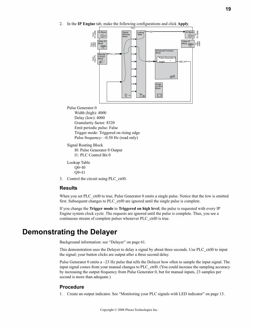
2. In the IP Engine tab, make the following configurations and click Apply.
Pulse Generator 0Width (high): 4000Delay (low): 4000Granularity factor: 8320Emit periodic pulse: FalseTrigger mode: Triggered on rising edgePulse frequency: ~0.50 Hz (read only)
Signal Routing BlockI0: Pulse Generator 0 OutputI1: PLC Control Bit 0
Lookup TableQ0=I0Q9=I1
3. Control the circuit using PLC_ctrl0.
ResultsWhen you set PLC_ctrl0 to true, Pulse Generator 0 emits a single pulse. Notice that the low is emitted first. Subsequent changes to PLC_ctrl0 are ignored until the single pulse is complete.
If you change the Trigger mode to Triggered on high level, the pulse is requested with every IP Engine system clock cycle. The requests are ignored until the pulse is complete. Thus, you see a continuous stream of complete pulses whenever PLC_ctrl0 is true.
Demonstrating the DelayerBackground information: see “Delayer” on page 61.
This demonstration uses the Delayer to delay a signal by about three seconds. Use PLC_ctrl0 to input the signal; your button clicks are output after a three second delay.
Pulse Generator 0 emits a ~23 Hz pulse that tells the Delayer how often to sample the input signal. The input signal comes from your manual changes to PLC_ctrl0. (You could increase the sampling accuracy by increasing the output frequency from Pulse Generator 0, but for manual inputs, 23 samples per second is more than adequate.)
Procedure1. Create an output indicator. See “Monitoring your PLC signals with LED indicator” on page 13.
LookupTable
SignalRoutingBlock
I0
I1
I2
I3
I4
I5
I7fro
mIO
cab
le
from
vide
oca
ble
toIO
cab
leto
vide
oca
ble
ImageControlBlock
IO Block
Video IOBlock
Video IOBlock
IO Block
Enhanced FunctionBlock
PLC
I6
RemoteControlBlockfro
mho
st P
C
Q0
Q9
Pulse Generator 0
trigger pg0_out
PLC_ctrl0
Copyright © 2008 Pleora Technologies Inc.

20 Demonstrating the PLC in 10 minutes
2. In the IP Engine tab, make the following configurations and click Apply.
Pulse Generator 0Width (high): 65535Delay (low): 65535Granularity factor: 10Emit periodic pulse: TrueTrigger mode: Not applicable (any setting is okay)Pulse frequency: ~23 Hz (read only)
Delayer 0Delay count: 69Reference timing signal: Pulse Generator 0 outputInput signal: Q3
Signal Routing BlockI0: PLC Control Bit 0I4: Delayer 0 output
Lookup TableQ3=I0Q0=I4
3. Control the circuit using PLC control bit 0.
ResultsWhen you set PLC_ctrl0 to true, the output becomes true after a three second delay. When you set it false, the output becomes false after three seconds. The output will always accurately track your inputs to PLC_ctrl0.
Demonstrating the RescalerBackground information: see “Rescaler” on page 60.
This demonstration uses the Rescaler to turn a 36 Hz pulse into a 3.6 Hz pulse. You can use PLC_ctrl0 to stop and start the 36 Hz input to the Rescaler.
Procedure1. Create an output indicator. See “Monitoring your PLC signals with LED indicator” on page 13.
LookupTable
SignalRoutingBlock
I0
I1
I2
I3
I4
I5
I7fro
mIO
cab
le
from
vide
oca
ble
toIO
cab
leto
vide
oca
ble
ImageControlBlock
IO Block
Video IOBlock
Video IOBlock
IO Block
Enhanced FunctionBlock
PLC
I6
RemoteControlBlockfro
mho
st P
C
del_out
Q0
Q3
Pulse Generator 0
Delayerinreference
pg0_out
PLC_ctrl0
Copyright © 2008 Pleora Technologies Inc.

21
2. In the IP Engine tab, make the following configurations and click Apply.
Pulse Generator 0Width (high): 65535Delay (low): 65535Granularity factor: 6Emit periodic pulse: TrueTrigger mode: Not applicable (any setting is okay)Pulse frequency: ~36 Hz (read only)
RescalerGranularity: 256 system clock cyclesMultiplier: Frequency X 16Divider: 160Input signal: Q3Backup enabled: FalseBackup input signal: Not applicable (any setting is okay)Target frequency: Not applicable (any setting is okay)
Signal Routing BlockI0: PLC Control Bit 0I4: Pulse Generator 0 outputI6: Rescaler 0 output
Lookup TableQ0=I6Q3=I0&I4
3. Control the circuit using PLC_ctrl0.
ResultsWhen PLC_ctrl0 is true, the 36 Hz signal from Pulse Generator 0 passes into the Rescaler and emerges as a 3.6 Hz signal. When PLC_ctrl0 is false, the 36 Hz signal is interrupted; the Rescaler’s output may stops, and may be either high or low.
Demonstrating the Rescaler (with backup)Background information: see “Rescaler” on page 60.
This demonstration uses the Rescaler to turn a 1001 Hz pulse into a 3.9 Hz pulse. However, if the 1001 Hz is interrupted, the Rescaler automatically outputs its backup pulse.
LookupTable
SignalRoutingBlock
I0
I1
I2
I3
I4
I5
I7fro
mIO
cab
le
from
vide
oca
ble
toIO
cab
leto
vide
oca
ble
ImageControlBlock
IO Block
Video IOBlock
Video IOBlock
IO Block
Enhanced FunctionBlock
PLC
I6
RemoteControlBlockfro
mho
st P
C
Q3
Pulse Generator 0
Rescalerinreference
pg0_out
PLC_ctrl0
Q0
rsl_out
Copyright © 2008 Pleora Technologies Inc.

22 Demonstrating the PLC in 10 minutes
Pulse Generator 0 generates the 1001 Hz signal which the Rescaler uses as its primary input. The Rescaler divides the signal frequency by about 256 (times 16, divided by 4095) and outputs the result as a rescaled 3.9 Hz pulse.
Pulse Generator 1 generates a 1.1 Hz signal that the Rescaler uses as a backup. If you interrupt the primary input, the Rescaler outputs the backup signal without rescaling it. You can interrupt the primary signal by setting PLC_ctrl0 to false.
Procedure1. Create an output indicator. See “Monitoring your PLC signals with LED indicator” on page 13.2. In the IP Engine tab, make the following configurations and click Apply.
Pulse Generator 0Width (high): 10Delay (low): 5Granularity factor: 2080Emit periodic pulse: TrueTrigger mode: Not applicable (any setting is okay)Pulse frequency: ~1001 Hz (read only)
Pulse Generator 1Width (high): 100Delay (low): 500Granularity factor: 50000Emit periodic pulse: TrueTrigger mode: Not applicable (any setting is okay)Pulse frequency: ~1.1 Hz (read only)
RescalerGranularity: 16 system clock cyclesMultiplier: Frequency X 16Divider: 4095Input signal: Q3Backup enabled: TrueBackup switchover delay: 4095Backup input signal: Pulse Generator #1Target frequency: Not applicable (any setting is okay)
Signal Routing BlockI0: PLC control bit 0I2: Pulse Generator 0 outputI4: Rescaler 0 output
LookupTable
SignalRoutingBlock
I0
I1
I2
I3
I4
I5
I7
from
IO c
able
from
vide
oca
ble
toIO
cab
leto
vide
oca
ble
ImageControlBlock
IO Block
Video IOBlock
Video IOBlock
IO Block
Enhanced FunctionBlock
PLC
I6
RemoteControlBlockfro
mho
st P
C
Q3
Pulse Generator 0
Rescalerinbackup
pg0_out
Pulse Generator 1pg1_out
rsl_out
Q0
PLC_ctrl0
Copyright © 2008 Pleora Technologies Inc.

23
Lookup TableQ3=I0&!I2Q0=I4
3. Control the circuit using PLC_ctrl0.
ResultsWhen PLC_ctrl0 is true, the PLC outputs a pulse that 3.9 Hz pulse. When PLC_ctrl0 is false, the output is a 1.1 Hz pulse.
The Backup switchover delay configures how long the Rescaler waits before switching to the backup signal. Configure this setting carefully. If you set this value too low (a value of 10), the Rescaler switches immediately to the backup signal because the wait is shorter than the input frequency. A value of 100 causes the Rescaler to switch back and forth.
Demonstrating the General Purpose CounterBackground information: see “General Purpose Counter” on page 62.
This demonstration uses the General Purpose Counter to keep a continuous count. You can use the PLC control bits to clear, decrement, or increment the count. When the count is greater than 4, the output is true.
Procedure1. Create an output indicator. See “Monitoring your PLC signals with LED indicator” on page 13.2. In the IP Engine tab, make the following configurations and click Apply.
CounterIncrement trigger mode: Rising edgeDecrement trigger mode: Rising edgeClear trigger mode: Rising edgeClear signal: Q3Compare value: 4
Signal Routing BlockI0: PLC control bit 0I1: PLC control bit 1I4: PLC control bit 2I7: Counter 0 Greater
Lookup TableQ3=I0Q16=I1
LookupTable
SignalRoutingBlock
I0
I1
I2
I3
I4
I5
I7
from
IO c
able
from
vide
oca
ble
toIO
cab
leto
vide
oca
ble
ImageControlBlock
IO Block
Video IOBlock
Video IOBlock
IO Block
Enhanced FunctionBlock
PLC
I6
RemoteControlBlockfro
mho
st P
C
Q3Q16Q17 gp_cnt_gt
Q0
General PurposeCounter
cleardownup
PLC_ctrl0PLC_ctrl1PLC_ctrl2
Copyright © 2008 Pleora Technologies Inc.
24 Demonstrating the PLC in 10 minutes
Q17=I4Q0=I7
3. Control the circuit using PLC_ctrl0, PLC_ctrl1, and PLC_ctrl2.
ResultsUse PLC_ctrl0 to clear the count value, PLC_ctrl1 to decrement it, and PLC_ctrl2 to increment it. If you decrement the count below 0, the value wraps around to 4294967295 (which is greater than 4). The control use rising edges, so two mouse clicks are required to make a change.
Demonstrating the Interrupt FIFOBackground information: see “Interrupt FIFO” on page 64.
This demonstration sends interrupt requests to your PC. The interrupts aren’t configured to do anything, but you can use Coyote to track them. This demonstration doesn’t use an output indicator, so the procedure differs slightly.
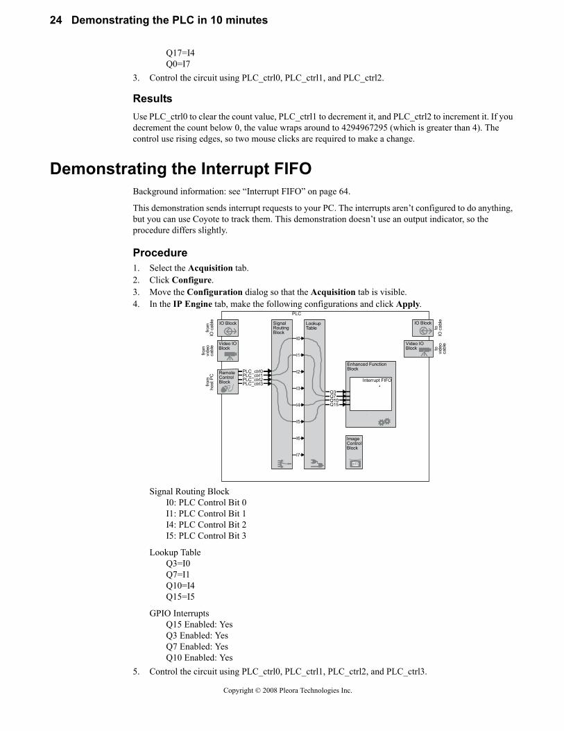
Procedure1. Select the Acquisition tab.2. Click Configure.3. Move the Configuration dialog so that the Acquisition tab is visible.4. In the IP Engine tab, make the following configurations and click Apply.
Signal Routing BlockI0: PLC Control Bit 0I1: PLC Control Bit 1I4: PLC Control Bit 2I5: PLC Control Bit 3
Lookup Table Q3=I0Q7=I1Q10=I4Q15=I5
GPIO InterruptsQ15 Enabled: YesQ3 Enabled: YesQ7 Enabled: YesQ10 Enabled: Yes
5. Control the circuit using PLC_ctrl0, PLC_ctrl1, PLC_ctrl2, and PLC_ctrl3.
LookupTable
SignalRoutingBlock
I0
I1
I2
I3
I4
I5
I7
from
IO c
able
from
vide
oca
ble
toIO
cab
leto
vide
oca
ble
ImageControlBlock
IO Block
Video IOBlock
Video IOBlock
IO Block
Enhanced FunctionBlock
PLC
I6
RemoteControlBlockfro
mho
st P
C
Q3Q7Q10Q15
Interrupt FIFO
PLC_ctrl0PLC_ctrl1PLC_ctrl2PLC_ctrl3
Copyright © 2008 Pleora Technologies Inc.

25
ResultsWhen you create a rising edge with any of the control bits, the IP Engine sends an interrupt request to the PC. Information about each interrupt appears in the PLC Interrupts entry on the Acquisition tab. (See the iPORT Coyote Software Guide.)
Copyright © 2008 Pleora Technologies Inc.

26 Demonstrating the PLC in 10 minutes
Copyright © 2008 Pleora Technologies Inc.

27
Configuring the PLC with the iPORT Vision Suite
In this section:Configuring the PLC with the SDK........................................................................... 27Configuring the PLC with Coyote ............................................................................. 27
Configuring the PLC with the SDKTo configure the PLC with the iPORT Vision Suite SDK:• See CyDevice in the iPORT C++ SDK Reference Guide.
Configuring the PLC with CoyoteCoyote lets you configure the entire PLC. Once configured, you can save the configuration file and reload it as you like. For a complete description of Coyote’s interface, see the iPORT Coyote Software Guide.
In this section:Saving your PLC configuration ................................................................................. 27Monitoring the IO Block............................................................................................ 27Manually controlling your circuit with the Remote Control Block........................... 28Configuring the IO Block .......................................................................................... 28Configuring the Video IO Block................................................................................ 29Configuring the Signal Routing Block ...................................................................... 29Configuring the Lookup Table................................................................................... 29Configuring the Input Routing Block ........................................................................ 29Configuring the Enhanced Function Block ............................................................... 29Configuring the Image Control Block ....................................................................... 29Configuring special PLC settings .............................................................................. 30
Saving your PLC configuration
To save your PLC configuration:• From the main page of Coyote, select File > Save.
See the iPORT Coyote Software Guide.
Monitoring the IO Block
To monitor the state of the input side of the IO Block:• From the main page of Coyote, select IP Engine > PLC Control Bits.
The PLC Control Bits dialog appears. The polled state of the IO Block appears in the IO Block status pane. If you’re monitoring feedback (“Monitoring your PLC signals with a feedback loop”
Copyright © 2008 Pleora Technologies Inc.

28 Configuring the PLC with the iPORT Vision Suite
on page 15), TTL_IN0 is typically A0, but consult your hardware guide to be sure. For a complete description of the dialog, see the iPORT Coyote Software Guide.
Manually controlling your circuit with the Remote Control Block
To set the Remote Control Block:1. From the main page of Coyote, select IP Engine > PLC Control Bits.
The PLC Control Bits dialog appears.
2. In the PLC Control Bit status pane, check and uncheck the Set value of PLC_ctrl0 through PLC_ctrl3.The IP Engine value shows the states of the bits in the actual IP Engine. Thus, the IP Engine value will follow the Set value pane. To learn more about the PLC Control Bits dialog, see the iPORT Coyote Software Guide.
NOTE! The propagation delay for registry entries (including the PLC control bits) depends on your CPU usage, Windows scheduling, network adapter speed, network traffic, and switch propagation times. Actual times will vary, but are in the order of tens of milliseconds. For hard realtime applications, create your IP Engine output signal using the Counter Trigger Generator. See “Counter Trigger Generator” on page 64.
Configuring the IO BlockExcept for the Debouncing Block, the IO Block doesn’t require any configuring.
To access the Debouncing Block configurations:• From the Configuration dialog, select IP Engine > Programmable Logic Controller > Input
Debouncing Block.For a description of the settings, see “Input Debouncing Block” on page 41.
Copyright © 2008 Pleora Technologies Inc.

29
Configuring the Video IO BlockThe Video IO Block doesn’t require any configuring.
Configuring the Signal Routing Block
To access the Signal Routing Block configurations from Coyote:• From the Configuration dialog, select the IP Engine > Programmable Logic Controller >
Signal Routing Block and Lookup Table.
Configuring the Lookup Table
To access the Lookup Table configurations:1. From the Configuration dialog, select IP Engine > Programmable Logic Controller > Signal
Routing Block and Lookup Table.2. Replace LOCKED with your Lookup Table configurations and click Apply.
NOTE! The Lookup Table configurations (Q1=I2, etc.) are automatically converted into a lookup table format. If you wish to make a change to the Lookup Table after closing and reopening Coyote, retype all the values. The values are maintained if you save the XML.
Configuring the Input Routing Block
To access the Input Routing Block configurations from Coyote:• From the Configuration dialog, select IP Engine > Programmable Logic Controller > Signal
Routing Block and Lookup Table.See “Signal Routing Block” on page 53.
Configuring the Enhanced Function Block
To access the Enhanced Functionality Block configurations from Coyote:1. From the Configuration dialog, select IP Engine > Programmable Logic Controller >
Enhanced Function Block.2. Select the function that you require (e.g. Pulse Generator 0, Delayer, etc.).3. Make changes as necessary and click Apply.See “Enhanced Function Block” on page 57.
To enable the Interrupt FIFO interrupts:1. From the Configuration dialog, select IP Engine > Programmable Logic Controller > PLC
Interrupts.2. Enable the interrupts that you require and click Apply.See “Interrupt FIFO” on page 64.
NOTE! To minimize unnecessary CPU usage, don’t enable interrupts that you don’t require.
Configuring the Image Control Block
To enable image triggering on Q14:1. From the Configuration dialog, select the Grabber tab.2. Enable PLC Triggerable.
You can now trigger the image grabber using signals sent to Q14.
To override the FVAL and LVAL settings:1. From the Configuration dialog, select the Grabber Extensions tab.
Copyright © 2008 Pleora Technologies Inc.

30 Configuring the PLC with the iPORT Vision Suite
2. Expand Camera Link. Change the Frame Valid function selection or Line Valid function selection as desired and click Apply.The grabber uses the Boolean combination that you select. See “Image Control Block” on page 67.
To configure the DVAL, LVAL, or FVAL polarity and edge sensitivity settings:1. From the Configuration dialog, select the Grabber Extensions tab.2. Expand Camera Link. Make changes as necessary and click Apply.See “Image Control Block” on page 67.
Configuring special PLC settings
To configure the special PLC settings:1. From the Configuration dialog, select IP Engine > Programmable Logic Controller > PLC
Configuration.2. Make changes as necessary and click Apply.
NOTE! Dropdowns with a value of 0, 1, 2, or 3 are null values that make no changes. IP Engines have very few special settings so most of the configurations are unused.
Copyright © 2008 Pleora Technologies Inc.

31
Configuring the PLC with the iPORT PureGEV Suite
GEV-enabled IP Engines generally match the behavior described in this guide, with a few exceptions. In general, the GEV-enabled IP Engines add the prefix PLC_ to the signal names.
To configure the PLC with AutoGEV:1. Configure the PLC as you require. See the iPORT AutoGEV Software Guide.2. Optionally, set the visibility attribute of unneeded or unchangeable features to invisible. 3. Optionally, create virtual features to control the PLC, and set the underlying features’ attributes to
invisible.4. Upload your project to your IP Engine.
To control the PLC with GEVPlayer:• Change the features in this section as required. To change features in GEVPlayer, see the iPORT
PureGEV Quick Start Guide.In this section:
IO Block..................................................................................................................... 31Video IO Block .......................................................................................................... 31Video IO Block .......................................................................................................... 31Signal Routing Block................................................................................................. 32Lookup Table ............................................................................................................. 32Enhanced Function Block.......................................................................................... 33Special PLC settings .................................................................................................. 37
IO BlockSee “IO Block” on page 39.
Video IO BlockThe Video IO Block doesn’t require any configuring.
IO Block features
Display name Name (identifier)
An (for n values 0 to 3) Linen
Copyright © 2008 Pleora Technologies Inc.

32 Configuring the PLC with the iPORT PureGEV Suite
See “Video IO Block” on page 47.
Remote Control BlockUnlike Coyote, which distinguishes the desired value (the value you set) from the actual value (the value in the IP Engine), the iPORT PureGEV Suite makes the distinction intrinsically.
See “Remote Control Block” on page 51.
Signal Routing BlockSee “Signal Routing Block” on page 53.
Lookup TableRather than accepting an equation in the form of a string, GEV-enabled IP Engines accept a series of separate variables and operators that you specify using dropdown selections. For example, to set...
Q0 = I5 & (I3 | I4)
... make the following settings:
Lookup TablePLC_Q0_Variable0 = PLC_I5PLC_Q0_Operator0 = AndParenthesisPLC_Q0_Variable1 = PLC_I3PLC_Q0_Operator1 = OrPLC_Q0_Variable2 = PLC_I4PLC_Q0_Operator2 = OrPLC_Q0_Variable3 = Zero
In this case, the equation supports 4 variables, though only 3 were used. To keep from unintentionally changing the value of your equation, extend short equations with Or Zero. Parentheses are closed auto-matically at the end of the equation. Thus, the finished iPORT PureGEV Suite equation would be:
Q0=I5 &( I3 | I4 | 0
... which is the iPORT PureGEV Suite equivalent of...
Video IO Block features
Display name Name (identifier)
An (for n values 4 to 7) PLC_An
Remote Control Block features
Display name Name (identifier)
PLC_CTRL0PLC_CTRLn (for n values of 0 through 3)
PLC_ctrl0PLC_ctrln
Signal Routing Block features
Display name Name (identifier)
I0 In (for n values of 0 through 7)
PLC_I0PLC_In
Copyright © 2008 Pleora Technologies Inc.
33
Q0 = I5 &(I3 | I4)
See “Lookup Table” on page 55.
Enhanced Function BlockSee “Enhanced Function Block” on page 57.
In this section:Pulse Generator.......................................................................................................... 33Rescaler...................................................................................................................... 34Delayer....................................................................................................................... 35General Purpose Counter ........................................................................................... 35Interrupt FIFO............................................................................................................ 35Counter Trigger Generator......................................................................................... 36Timestamp Counter.................................................................................................... 36
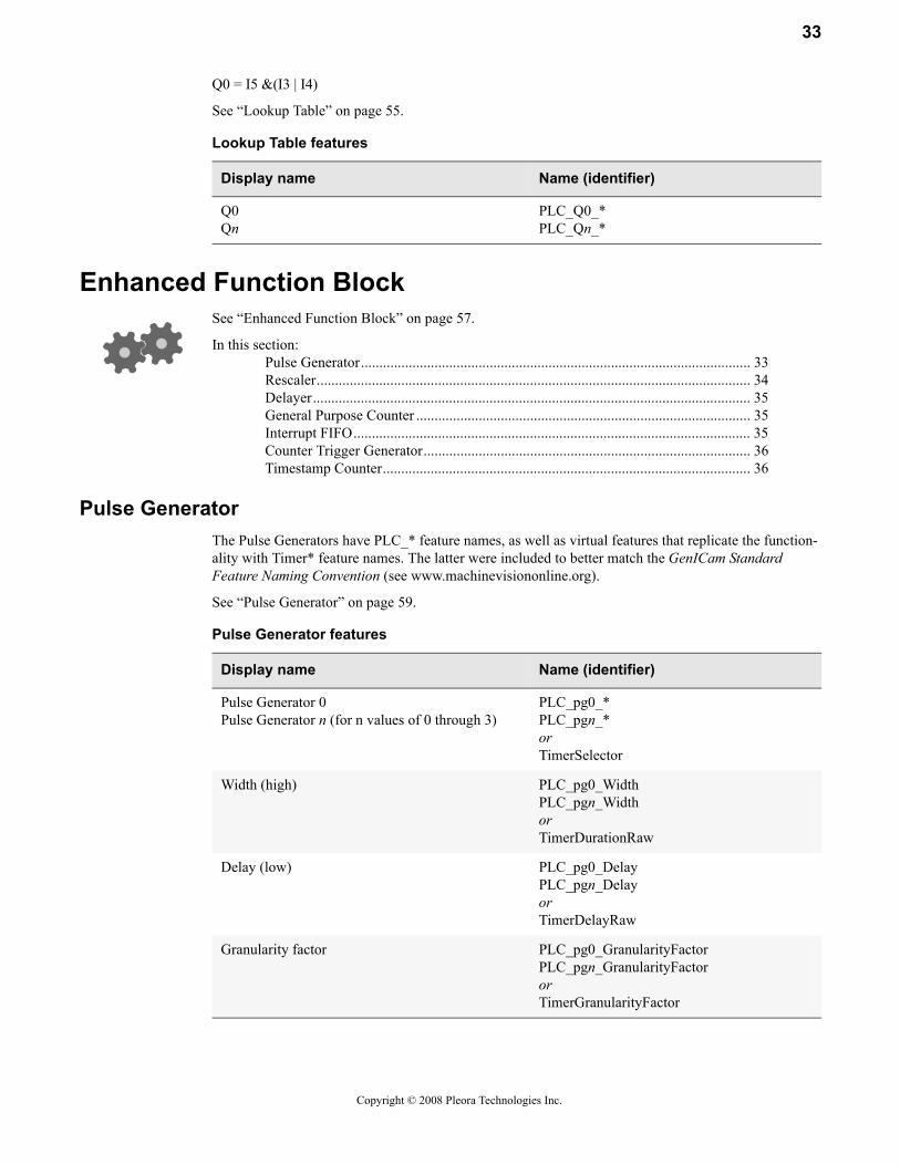
Pulse GeneratorThe Pulse Generators have PLC_* feature names, as well as virtual features that replicate the function-ality with Timer* feature names. The latter were included to better match the GenICam Standard Feature Naming Convention (see www.machinevisiononline.org).
See “Pulse Generator” on page 59.
Lookup Table features
Display name Name (identifier)
Q0Qn
PLC_Q0_*PLC_Qn_*
Pulse Generator features
Display name Name (identifier)
Pulse Generator 0Pulse Generator n (for n values of 0 through 3)
PLC_pg0_*PLC_pgn_*orTimerSelector
Width (high) PLC_pg0_WidthPLC_pgn_WidthorTimerDurationRaw
Delay (low) PLC_pg0_Delay PLC_pgn_DelayorTimerDelayRaw
Granularity factor PLC_pg0_GranularityFactor PLC_pgn_GranularityFactororTimerGranularityFactor
Copyright © 2008 Pleora Technologies Inc.

34 Configuring the PLC with the iPORT PureGEV Suite
RescalerSee “Rescaler” on page 60.
Emit periodic pulse PLC_pg0_TriggerSourcePLC_pgn_TriggerSourceorTimerTriggerSource
Trigger mode PLC_pg0_TriggerActivationPLC_pgn_TriggerActivationorTimerTriggerSource
Pulse period (ns) PLC_pg0_PulsePeriodPLC_pgn_PulsePeriodorTimerPeriod
Pulse frequency (Hz) PLC_pg0_PulseFrequencyPLC_pgn_PulseFrequencyorTimerFrequency
Pulse Generator features
Display name Name (identifier)
Rescaler features
Display name Name (identifier)
Granularity PLC_rsl0_Granularity
Multiplier PLC_rsl0_Multiplier
Divider PLC_rsl0_Divider
Input signal PLC_rsl0_InputSignal
Backup enabled PLC_rsl0_BackupEnabled
Backup switchover delay PLC_rsl0_BackupSwitchoverDelay
Backup input signal PLC_rsl0_BackupInputSignal
Input frequency PLC_rsl0_InputFrequency
Output frequency PLC_rsl0_OutputFrequency
Target frequency Recommended granularityRecommended multiplierRecommended divider
Not available
Rescaler sample size PLC_rsl0_SampleSize
PLC_rsl_out PLC_rsl0_out
Copyright © 2008 Pleora Technologies Inc.

35
DelayerSee “Delayer” on page 61.
General Purpose CounterSee “General Purpose Counter” on page 62.
Interrupt FIFOSee “Interrupt FIFO” on page 64.
Delayer features
Display name Name (identifier)
Delay count PLC_del0_DelayCount
Reference timing signal PLC_del0_ReferenceTimingSignal
Input signal PLC_del0_InputSignal
del_out PLC_del0_out
General Purpose Counter features
Display name Name (identifier)
Increment trigger mode PLC_gp_cnt0_IncrementActivation
Decrement trigger mode PLC_gp_cnt0_DecrementActivation
Clear trigger mode PLC_gp_cnt0_ResetActivation
Clear signal PLC_gp_cnt0_ResetSource
Compare value PLC_gp_cnt0_CompareValue
Current counter value PLC_gp_cnt0_Value
gp_cnt_eq Counter1Eq
gp_cnt_gt Counter1Gt
Interrupt FIFO features
Display name Name (identifier)
Q15 Enabled PLC_Interrupt_FIFO0_Q15_Enabled
Q3 Enabled PLC_Interrupt_FIFO0_Q3_Enabled
Q7 Enabled PLC_Interrupt_FIFO0_Q7_Enabled
Q10 Enabled PLC_Interrupt_FIFO0_Q10_Enabled
IRQ_mask[3:0] PLC_Interrupt_FIFO0_IRQ_mask
time[31:0] PLC_Interrupt_FIFO0_time
SRB_mask[7:0] PLC_Interrupt_FIFO0_SRB_mask
Copyright © 2008 Pleora Technologies Inc.

36 Configuring the PLC with the iPORT PureGEV Suite
Counter Trigger GeneratorSee “Counter Trigger Generator” on page 64.
Timestamp CounterThe Timestamp Counter varies slightly from that described See “Timestamp Counter” on page 65.
Counter Trigger Generator features
Display name Name (identifier)
FIFO full PLC_ts_trig_FIFOFull
FIFO empty PLC_ts_trig_FIFOEmpty
Trigger mask values PLC_ts_trig_0_EnablePLC_ts_trig_1_EnablePLC_ts_trig_2_EnablePLC_ts_trig_3_Enable
Counter selector PLC_ts_trig_CounterSelect
Trigger’s time PLC_ts_trig_Time
Arm command PLC_ts_trig_Arm
ts_trign PLC_ts_trign
Timestamp Counter features
Display name Name (identifier)
Counter select CounterSelector
Granularity Not available
Set trigger mode CounterTriggerSource
Clear trigger mode CounterResetActivation
Set input signal Counter
Clear input signal CounterResetSource
Broadcast Not available
Set counter valueCurrent counter value
CounterValue
Copyright © 2008 Pleora Technologies Inc.

37
Special PLC settingsSee “Configuring special PLC settings” on page 30.
Special PLC settings
Display name Name (identifier)
PLC Configuration Line0ConfigurationLinenConfigurationPLC_Q0_ConfigurationPLC_Qn_Configuration
Copyright © 2008 Pleora Technologies Inc.

38 Configuring the PLC with the iPORT PureGEV Suite
Copyright © 2008 Pleora Technologies Inc.

39
IO Block
The IO Block lets you communicate with the PLC through the IP Engine’s 12-pin IO connector. The IO Block consists of an input (on the left) and an output (on the right).
The main function of the IO Block is to convert external signals to low voltage TTL signals usable by the PLC (and vice versa). This section describes the electrical circuits used to convert between PLC signals and external TTL, LVDS, and optically-isolated signals. The IO Block filters inputs and outputs to reduce the risk of damage due to electrostatic discharge (ESD) and accidental shorts.
Except for the Input Debouncing Block, the IO Block doesn’t need to be configured.
Copyright © 2008 Pleora Technologies Inc.

40 IO Block
The pinouts on the IP Engine’s IO connector vary depending on your model; for the specific pinouts for yours, see your hardware guide. For example, the IO Block for your IP Engine might have several TTL inputs and outputs, an optically-isolated input and output, but no LVDS input.
To configure the IO Block, see “Configuring the IO Block” on page 28.
In this section:Monitoring the state of the IO Block ......................................................................... 40Synchronization Block............................................................................................... 40Input Debouncing Block............................................................................................ 41TTL Input Block ........................................................................................................ 42TTL Output Block ..................................................................................................... 43LVDS Input Block ..................................................................................................... 43Optically Isolated Input Block................................................................................... 44Optically Isolated Output Block ................................................................................ 45
Monitoring the state of the IO BlockPleora’s Coyote camera interface application lets you monitor the state of the input side (left side) of the IO Block. Your PC polls the state of the IP Engine’s IO Block at a rate of about 4 Hz and displays the results in the IO Block status pane. See “Monitoring the IO Block” on page 27.
Synchronization BlockThe Synchronization Block samples input signals in time with the IP Engine’s system clock. (Both the IO Block and the Video IO Block have Synchronization Blocks within.) The system clock has a 30 ns
Copyright © 2008 Pleora Technologies Inc.

41
period (33 MHz clock cycle). To maximize stability of the input signals and minimize the risk of meta-stability problems, the Synchronization Block uses two consecutive flip-flops.
The Synchronization Block latches the input on every rising edge of the system clock.
Input Debouncing BlockThe Input Debouncing Block lets you ignore spurious transitions from input signals A0-A3.
Synchronization Block specifications
Specification Value
Propagation delay minimum: 30 nsmaximum: 60 ns
Copyright © 2008 Pleora Technologies Inc.

42 IO Block
You can independently configure each input signal to hold signal transitions for between 480 ns and ~31 ms. While holding the first transition, the Input Debouncing Block ignores further transitions for the duration that you’ve configured.
The hold times can be configured in increments of 480 ns (16 system clock cycles). Setting the hold value to 0 disables the Input Debouncing Block for that input signal.
Hold time = Hold value * 480 ns
TTL Input BlockThe TTL Input Block accepts a TTL signal (0 V - 5.0 V) and converts it to a signal usable by the Signal Routing Block. The TTL Input Block uses the ground on the IO connector.
TTL Input Block specifications
Specification Value
Maximum input frequency 16.5 MHz
Termination 200 ohms serial
Input current minimum: 0 nAmaximum: 20 uA
Input voltage maximum low 0.9 V
Input voltage minimum high 2.1 V
Copyright © 2008 Pleora Technologies Inc.
43
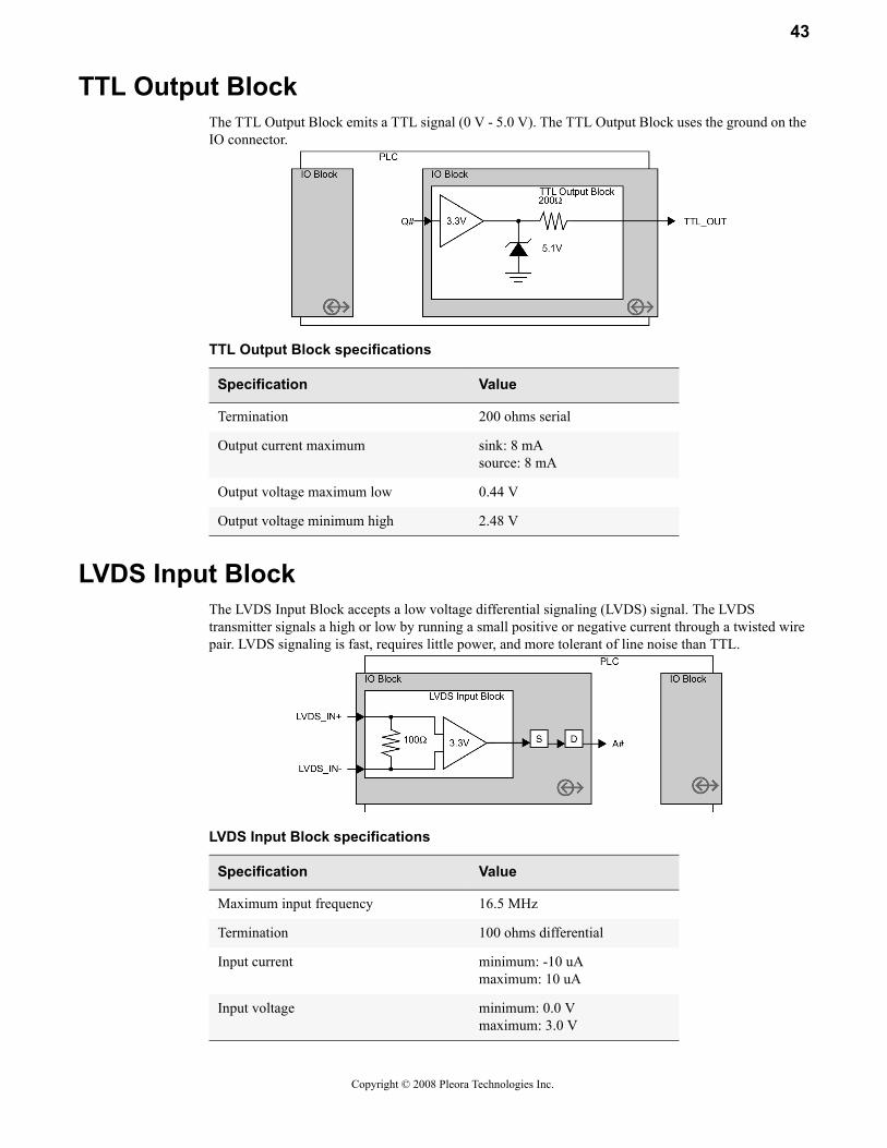
TTL Output BlockThe TTL Output Block emits a TTL signal (0 V - 5.0 V). The TTL Output Block uses the ground on the IO connector.
LVDS Input BlockThe LVDS Input Block accepts a low voltage differential signaling (LVDS) signal. The LVDS transmitter signals a high or low by running a small positive or negative current through a twisted wire pair. LVDS signaling is fast, requires little power, and more tolerant of line noise than TTL.
TTL Output Block specifications
Specification Value
Termination 200 ohms serial
Output current maximum sink: 8 mAsource: 8 mA
Output voltage maximum low 0.44 V
Output voltage minimum high 2.48 V
LVDS Input Block specifications
Specification Value
Maximum input frequency 16.5 MHz
Termination 100 ohms differential
Input current minimum: -10 uAmaximum: 10 uA
Input voltage minimum: 0.0 Vmaximum: 3.0 V
Copyright © 2008 Pleora Technologies Inc.

44 IO Block
Optically Isolated Input BlockThe Optically Isolated Input Block uses an LED and a light sensor to electrically decouple the IP Engine from the device that sends the signal. Optoisolators reduce the risk of an overvoltage problem causing collateral damage. They also let a machine with a noisy ground or a different ground voltage level communicate without affecting the IP Engine. Compared with TTL inputs, the response time of optoisolators is relatively slow, particularly for falling edges
The Optically Isolated Input Block accepts a 0 V - 5 V signal.
Response time test circuitThe actual response time for an optoisolator depends on the current load and the voltage level that constitutes a high or low signal. Below is the test circuit used to measure response times.
Optically Isolated Input Block specifications
Specification Value
Termination 200 ohms serial
Input threshold voltage 1.44 V
Input current of low minimum: 0.0 uAmaximum: 20.0 uA
Input current of high minimum: 4.5 mAmaximum: 19.0 mA
Input voltage of low minimum: 0.0 Vmaximum: 0.8 V
Input voltage of high minimum: 2.0 Vmaximum: 5.0 V
Copyright © 2008 Pleora Technologies Inc.

45
Optically Isolated Output BlockThe Optically Isolated Output Block is an open-collector circuit that manipulates an external pull-up voltage to produce a 0 V - 5 V signal. For an overview of optoisolators, see “Optically Isolated Input Block” on page 44.
Optically Isolated Output Block response time test circuit specifications
Specification Value
Edge response time rising: 2.11 usfalling: 30.56 us
Optically Isolated Output Block specifications
Specification Value
Termination 200 ohms serial
Output current minimum: 0.0 mAmaximum: 25.0 mA
Output voltage minimum: 0.0 Vmaximum: 5.0 V
Copyright © 2008 Pleora Technologies Inc.

46 IO Block
Response time test circuitThe actual response time for an optoisolator depends on the current load and the voltage level that constitutes a high or low signal. Below is the test circuit used to measure response times.
Optically Isolated Output Block response time test circuit specifications
Specification Value
Output voltage minimum: 0.5 Vmaximum: 5.0 V
Edge response time rising: 32.89 usfalling: 2.89 us
Copyright © 2008 Pleora Technologies Inc.

47
Video IO Block
The Video IO Block receives a video signal and provides the PLC with discrete frame valid (FVAL), line valid (LVAL), and similar signals. Some camera signal types permit camera control signals from the IP Engine. The Video IO Block consists of an input (on the left) and an output for camera control (on the right). The exact functionality of the Video IO Block depends on the video input format (e.g. Camera Link, analog video, etc.) and the features the format supports.
The Video IO Block doesn’t need to be configured.
In this section:How the Video IO Block works................................................................................. 47Video IO Block (for Camera Link imaging data) ...................................................... 48Video IO Block (for analog video) ............................................................................ 48Video IO Block (for LVDS imaging data) ................................................................. 49
How the Video IO Block worksThe Video IO Block on your IP Engine can support Camera Link imaging data, analog video, or LVDS imaging data. All three camera signal formats have signals that let you (and the IP Engine’s image grabber) distinguish frames and lines from each other. However, the formats differ from each other. Internally, the IP Engine converts the signal format to conform to the Camera Link standard.
The Camera Link standard defines each of the input signals:
FVALFrame Valid. High for valid lines. (In practice, this lets you separate one frame from another.)
Copyright © 2008 Pleora Technologies Inc.

48 Video IO Block
LVALLine Valid. High for valid pixels. (In practice, it separates one line from another.)
DVALData Valid. High when data is valid (i.e. high for each pixel).
SPRSpare. A spare line for future use by the Camera Link standard.
The Camera Link Video IO Block and the LVDS Video IO Block use the actual signals sent through the video cable.
For analog video signals, the FVAL and LVAL signals are akin to the vertical-retrace and horizontal-retrace signals. However, the DVAL and SPR signals are of little significance for an analog camera signal, so the Analog Video IO Block replaces them with different signals:
RTS1The Real-time status. For Black and White Progressive Mode, RTS1 is “Horizontal sync” and provides a pulse at the beginning of a line. Otherwise, the signal is equivalent to “Vertical and Horizontal lock.” The signal is high when the Analog Video Decoder detects a valid signal and is locked horizontally. Thus, for a good signal, it is always high.
FIDThe field identifier.For interlaced signals, FID identifies all “even” lines of an interlaced video signal with a 0; all “odd” with a 1. For progressive video signals, FID remains 0.
Although the Camera Link standard defines the FVAL and LVAL signals, some cameras may invert the signals or otherwise differ from the standard. To manipulate the FVAL, LVAL signals for controlling how the IP Engine’s image grabber acquires images, see “Image Control Block” on page 67.
Video IO Block (for Camera Link imaging data)The Camera Link Video IO Block sends and receives its signal from the 26-pin Camera Link connector. The Camera Link standard transmits the FVAL, LVAL, DVAL, and spare signals over the Camera Link bus. The camera control signals use discrete LVDS outputs.
Video IO Block (for analog video)The Analog Video IO Block receives its signal from the coaxial cable attached to the BNC connector. The Analog Video IO Block interprets the signal and outputs the FVAL, DVAL, RTS1, and FID signals on discrete lines. Analog video transmission is one-way only; the format doesn’t let you send camera
Copyright © 2008 Pleora Technologies Inc.

49
control signals back to the camera using the video output cable. However, if your camera accepts external controls, you can use the IP Engine to send controls using the IO Block.
Video IO Block (for LVDS imaging data)The LVDS Video IO Block receives its signal through the cable attached to the 68-pin LVDS connector. The LVDS Video IO Block receives and sends signals through discrete lines (i.e. FVAL, CC1, and other signals each have their own unshared line).
Copyright © 2008 Pleora Technologies Inc.

50 Video IO Block
Copyright © 2008 Pleora Technologies Inc.

51
Remote Control Block
The Remote Control Block lets you send input signals to your IP Engine from Coyote. You can use these signals to simulate the inputs from switches, sensors, and other hardware without having to cable the actual equipment together. The input signals are called PLC control bits.
Within the IP Engine, the PLC control bits are binary registers that can be set and read using the iPORT SDK.
To use the Remote Control Block, see “Manually controlling your circuit with the Remote Control Block” on page 28.
Copyright © 2008 Pleora Technologies Inc.

52 Remote Control Block
Copyright © 2008 Pleora Technologies Inc.

53
Signal Routing Block
In its simplest terms, the Signal Routing Block is a group of switches that let you route signals to the Lookup Table. You can direct PLC inputs and feedback inputs to signals I0 through I7.
The Signal Routing Block lets you redirect signals from the IO Block, the Video IO Block, Lookup Table, and the Enhanced Function Block back into the Lookup Table for further processing. Because most of the other blocks in the PLC use preconfigured inputs and outputs, the Signal Routing Block is the primary method of routing a signal from one block to another.
To configure the Signal Routing Block, see “Configuring the Signal Routing Block” on page 29.
How the Signal Routing Block worksThe Signal Routing Block has 8 outputs (I0 - I7). Each output uses a 16:1 multiplexer that connects to 16 inputs.
LookupTable
SignalRoutingBlock
I0
I1
I2
I3
I4
I5
I7
from
IO c
able
from
vide
oca
ble
toIO
cab
leto
vide
oca
ble
ImageControlBlock
IO Block
Video IOBlock
Video IOBlock
IO Block
Enhanced FunctionBlock
PLC
I6
RemoteControlBlockfro
mho
st P
C PLC_ctrl1
A0
A4
A6
Signal Routing Block before configuring
LookupTable
SignalRoutingBlock
I0
I1
I2
I3
I4
I5
I7
from
IO c
able
from
vide
oca
ble
toIO
cab
leto
vide
oca
ble
ImageControlBlock
IO Block
Video IOBlock
Video IOBlock
IO Block
Enhanced FunctionBlock
PLC
I6
RemoteControlBlockfro
mho
st P
C PLC_ctrl1
A0
A4
A6
Signal Routing Block before configuringSignal Routing Block after configuring
Copyright © 2008 Pleora Technologies Inc.

54 Signal Routing Block
The Signal Routing Block has more than 16 input signals, so not every input can be connected to every one of signals I0 - I7. However, signals I0 - I7 are functionally identical, so connecting to a specific one isn’t important. If you can’t route the input with your first choice, simply choose another.
Copyright © 2008 Pleora Technologies Inc.

55
Lookup Table
The Lookup Table lets you connect any input signal I0-I7 to any Lookup Table output signal Q0-Q17.
You can manipulate your inputs using simple or complex Boolean expressions. The following expressions are both valid:
Q0 = I6
Q6 = !(I4 & I6) & ((I2 ^ I5) | I1)
Lookup Table syntax
Syntax Valid construction Sample line
Line Output = Expression EOL (end of line)
Output Q0, Q1, Q2, ..., Q16, Q17
Input I0, I1, I2, ..., I6, I7
Expression InputNot InputBoolean constant
Q1=I5Q1=!I5Q1=FALSE
Combined Expression Expression Boolean operator Expression Q1=I5 & I3Q16 = I8 | I6
Boolean operators & (and)| (or)^ (xor)
Q14 = I4 & I6Q15 = I3 | I5Q9 = I1 ^ I8
Copyright © 2008 Pleora Technologies Inc.

56 Lookup Table
To configure the Lookup Table, see “Configuring the Lookup Table” on page 29.
How the Lookup Table worksThe Lookup Table has 8 inputs (I0 - I7) capable of two states each (true, false). Thus, the outputs have a total number of 256 input combinations. The result of each combination can be 1 or 0.
When you modify the equations in the Lookup Table, Coyote calculates the results of all 256 input com-binations and stores the result of each output as a 256-bit lookup table (hence the name). There are 18 outputs (Q0 - Q17), so Coyote calculates 18 different lookup tables.
Coyote then passes the resulting 18 lookup tables to the IP Engine. Knowing the value of the 8 inputs, the PLC needs only look up the value of the resulting output (for each output), rather than calculate it. Thus, the Lookup Table can achieve a propagation delay of only one system clock cycle (30 ns), regardless of the complexity or number of Boolean expressions.
Not ! Q0=!I0Q10= !(I8 & I5)
Delimiter ( ) Q0 = !(I0)Q3 = !(I1 | (I7 ^ I5))Q6 = (I3 | I5) ^ (I1 & I2)
Boolean constants 1, true, TRUE0, false, FALSE
Q0 = 1Q3 = TRUEQ6 = I3 ^ true
EOL \r\n\r\n\n\r
(used only for SDK, not Coyote)
Incorrect Lookup Table usage
Rule Incorrect syntax Correct syntax
The output must be on the left hand side of the equation (the value is being assigned to Q4, not I5).
I5 = Q4 Q4 = I5
Outputs may not be on the right hand side of the equa-tion.
Q1 = I7 & I8Q2 = Q1 | I5
Q1 = I7 & I8Q2 = (I7 & I8) | I5
Equations must be separated by a carriage return or an EOL symbol.
Q3 = I7,Q15=I8 Q3 = I7Q15 = I8
Lookup Table syntax
Syntax Valid construction Sample line
Copyright © 2008 Pleora Technologies Inc.

57
Enhanced Function Block
The Enhanced Functionality Block lets you perform complex functions on your signals. You can delay a signal, generate a pulsed signal, count pulses, generate interrupts to the PC, and more.
To configure the Enhanced Function Block, see “Configuring the Enhanced Function Block” on page 29.
In this section:Overview of the Enhanced Function Block............................................................... 58Pulse Generator.......................................................................................................... 59Rescaler...................................................................................................................... 60Delayer....................................................................................................................... 61General Purpose Counter ........................................................................................... 62Interrupt FIFO............................................................................................................ 64Counter Trigger Generator......................................................................................... 64Timestamp Counter.................................................................................................... 65
Copyright © 2008 Pleora Technologies Inc.

58 Enhanced Function Block
Overview of the Enhanced Function BlockThe Enhanced Function Block includes many discrete, independent functions.
Brief summaries of the parts of the Enhanced Function BlockPulse Generator
Create a pulse.
RescalerAdjust the frequency of an input signal.
DelayerDelay a complex signal.
Interrupt FIFOSend an interrupt request to the PC.
General Purpose CounterCount pulses (such as from the encoder on a conveyor belt).
Timestamp CounterUse the IP Engine’s onboard clock.
Counter Trigger GeneratorSet an “alarm clock” that outputs up to four signals.
Copyright © 2008 Pleora Technologies Inc.

59
Put together, the parts of the Enhanced Function Block let you create very complex functionality!
Pulse GeneratorThe Pulse Generator lets you create a pulsed digital signal with a configurable frequency and duty cycle. You can configure the Pulse Generator to emit a continuous (periodic) pulse.
You can also configure the Pulse Generator to emit a single pulse after receiving an input trigger signal. The Pulse Generator outputs the low section of the pulse first, which lets you include a built-in delay. Subsequent inputs are ignored until the Pulse Generator completes its pulse.
Depending on the model, your iPORT IP Engine may have up to four Pulse Generators, numbered 0 through 3.
Pulse Generator formulas
Pulse Generator settingsWidth (high)
The relative duration of the high section of the pulse. A value of 0 is treated as 1.
Delay (low)The relative duration of the low section of the pulse. A value of 0 is treated as 1.
Granularity factorA multiplier used to scale the Width (high) and Delay (low) in increments of 30 ns.
Emit periodic pulseWhen checked, the Pulse Generator emits a continuous signal; when unchecked, the Pulse Generator emits pulses only when triggered by an input signal. The input signal for each Pulse Generator is fixed; see “The PLC at a glance” on page 75.
Trigger modeThe event that causes the Pulse Generator to emit pulses. If the mode is an edge, the Pulse Generator emits a single pulse; if the mode is a high or low state, the Pulse Generator emits pulses for as long as the condition is true. The Pulse Generator emits a complete pulse, even if the trigger condition becomes false before completion.
durationOfHigh granularity 1+( ) width 30ns××=
durationOfLow granularity 1+( ) delay 1+( )× 30ns×=
pulsePeriod durationOfHigh durationOfLow+=
pulseFrequency 1pulsePeriod--------------------------------=
Copyright © 2008 Pleora Technologies Inc.

60 Enhanced Function Block
Pulse period (ns)The duration of the full pulse. (read only)
Pulse Frequency (Hz)The number of pulse repetitions per second. (read only)
RescalerThe Rescaler lets you change the frequency of a periodic input signal. You can use the Rescaler to multiply the period by up to 4096 or divide it by up to 4095.
The Rescaler samples the frequency of the input signal, calculates the new output frequency, and emits a clock with a 50% duty cycle.
In input and output signals will not always align with each other. For example, an input period that is rescaled by 31.8 will rarely coincide with the output.
During its sample range, the Rescaler samples the input signal up to 65536 times (for 16-bit Rescalers). Based on its samples, the Rescaler determines the period of the input signal. To accurately sample your input signal, the sample duration should be as close as possible to the input period while still being longer.
The Rescaler samples at a rate determined by the Granularity; the maximum number of samples the Rescaler can take is determined by the Rescaler Size
Rescaler formulas
(The granularity is 1, 4, 16, or 256 system clock cycles)
(The rescalerSize is 12 or 16)
timeBetweenSamples granularity 30ns×=
maximumNumberOfSamples 2rescalerSize=
Copyright © 2008 Pleora Technologies Inc.

61
Rescaler settingsGranularity
The duration between samples, measured in system clock cycles (30 ns).
MultiplierDivider
Variables that let you scale the frequency of the output signal.
Input signalThe source of the input signal to be rescaled.
Backup enabledWhen enabled, the Rescaler switches to the Backup input signal should the Input signal stop.
Backup switchover delayThe duration of the delay to switchover, in increments of 480 ns. If the Rescaler detects no activity from the Input signal for backupWindow * 480 ns, it switches to the backup signal.
Backup input signalThe source of the replacement signal to be used if the Input signal stops. The Backup input signal isn’t rescaled.
Input frequencyThe pulse rate of the Input signal.
Output frequencyThe pulse rate of the output from the Rescaler.
Target frequencyA calculator that reads the Input frequency and recommends settings for Granularity, Multiplier, and Divider. The value of the Target frequency doesn’t affect the operation of the Rescaler.
Recommended granularityRecommended multiplierRecommended divider
Suggested settings based on the value set in the Target frequency.
Rescaler sample sizeThe maximum number of samples the Rescaler can take of the input signal before calculating the pulse width. The more samples the Rescaler makes, the more accurate the calculated pulse width. The 16-bit Rescaler takes up to 65356; the 12-bit, 4096.
DelayerThe Delayer lets you delay an input trigger signal.
outputFrequency inputFrequency multipler×divider
-------------------------------------------------------------------------=
maximumSampledPeriod granularity maximumNumberOfSamples 30ns××=
delayToSwitchOver backupWindow 480ns×=
Copyright © 2008 Pleora Technologies Inc.

62 Enhanced Function Block
The Delayer uses the rising edges of a periodic reference signal for timing. On each rising edge of the reference signal, the Delayer samples the input signal. After n pulses (up to 65535) of the reference signal, the Delay outputs the sampled value. The Delayer can store up to 128 transitions (64 pulses).
Because the Delayer uses the reference timing signal for sampling, input pulses that are shorter than the period of the reference timing signal could be missed. Additionally, output granularity will be that of the reference timing signal.
To determine the length of the delay, select a reference signal and specify the number of rising edges that must occur before relaying the input trigger signal.
Delayer formulas
Delayer settingsDelay count
The duration of the delay of the output signal, measured by the number of rising edges of the reference signal.
Reference timing signalThe source of the signal used for timing. The period of the reference signal determines both how often the Delayer samples the input and the duration of a delay count of 1.
Input signalThe source of the signal to be delayed.
General Purpose CounterThe General Purpose Counter lets you maintain a count between 0 and 232-1 (long integer). You can use different inputs to increment, decrement, or clear the counter value.
signalDelayTime periodOfReferenceSignal delayCount×=
Copyright © 2008 Pleora Technologies Inc.

63
The General Purpose Counter outputs two separate signals that indicate when the count is equal to and greater than the compare value that you set.
General Purpose Counter settingsIncrement trigger modeDecrement trigger modeClear trigger mode
The states that cause the count to increment, decrement, and set to 0. You can change the count using edges (rising, falling, or both) or by level (high or low). If you use edge mode, the count changes when the edge occurs.
If you use level mode, the count changes with every system clock pulse.
Increments and decrements that occur simultaneously cancel each other. A clear trigger overrides other changes and sets the count to zero.
Clear signalThe input signal that triggers the clearing of the counter.
Compare valueThe long integer to which the counter compares the Current counter value. The Counter outputs the result of the compare on the Greater Than and Equal To signals.
Current counter valueA read-only output of the current count. Coyote polls the IP Engine and updates the value every ~0.25 s.
Copyright © 2008 Pleora Technologies Inc.

64 Enhanced Function Block
Interrupt FIFOThe Interrupt FIFO lets you use the PLC to generate an interrupt on the host PC. The IP Engine sends an interrupt request (IRQ) packet containing the following:
• The values (state) of the four possible interrupt signals (IRQ_mask[3:0]);• The time. The value can be the count of either General Purpose Counter or the Timestamp
Counter (time[31:0]). To select a counter, use the “Counter select” configuration; see “Timestamp Counter” on page 65.
• The values (state) of I0-I7 in the Signal Routing Block (SRB_mask[7:0]).To let the iPORT SDK act on the IRQ, you must register a callback function. That callback function will be invoked every time the PC receives an IRQ packet. See the CyDevice class in the iPORT C++ SDK Reference Guide.
Interrupt FIFO settingsQ15 EnabledQ3 EnabledQ7 EnabledQ10 Enabled
When enabled, a rising edge on the signal (Q15, etc.) generates an IRQ packet. The SRB mask correctly reflects the state of the four signals, even if some of them are disabled.
Counter Trigger GeneratorThe Counter Trigger Generator lets you configure the IP Engine to monitor a counter and emit a signal while the count equals a desired value. When the count equals the set value, the Counter Trigger Generator emits a signal on up to four outputs. These signals feed into the Signal Routing Block and can be used to trigger other events.
The Counter Trigger Generator lets you set up to 32 simultaneous count values for monitoring. Once an event occurs, it is automatically removed from the pool. You can monitor the count from either the General Purpose Counter or the Timestamp Counter. You can also switch back and forth between the two. However, to ensure that no events are accidentally lost, the trigger list must be empty before switching from one counter to another.
The Counter Trigger Generator uses a first-in, first-out algorithm, so a trigger list of 4, 82, 8, would require the clock to roll over before acting on the count value of 8.
The Counter Trigger Generator must be set from the iPORT SDK; see the iPORT C++ SDK Reference Guide.
Copyright © 2008 Pleora Technologies Inc.

65
Timestamp CounterThe Timestamp Counter is a configurable counter based on the IP Engine’s system clock.
Timestamp Counter settingsCounter select
The signal used by the Interrupt FIFO. The time is also included in the footer of images sent from the IP Engine to the PC. (The counter selection for the Counter Trigger Generator is an independent setting made using the SDK).
GranularityThe amount of time that passes between counter increments. The minimum granularity is 480 ns, or 16 pulses of the 30 ns system clock. Because granularities of 1 us, 100 us, and 10 ms aren’t evenly divisible by 30 ns, the IP Engine prevents drift by adjusting the number of system clock pulses between counter increments. For example, by cycling through increment times of 0.990 us, 0.990 us, and 1.020 us, the clock maintains an average granularity of 1.000 us. The variance between individual counter increments is +/- 20 ns; the maximum counter variance is +/- 10 ns.
Set trigger modeClear trigger mode
The events that cause the Current counter value to change to the Set value or to 0.
Set input signalClear input signal
The signal used to set the counter to Set value or 0.
BroadcastWhen enabled, you can set or clear the counters of all networked IP Engines simultaneously. To use it, configure Set mode/Clear mode to On Apply. When you click Apply in the Con-figuration dialog, the PC sends out a packet containing the new counter value. Latency and variability depend on your networking equipment.
Set counter valueThe value to be set in the counter when the set event occurs.
Current counter valueThe current value of the counter. (Read only)
Copyright © 2008 Pleora Technologies Inc.

66 Enhanced Function Block
Copyright © 2008 Pleora Technologies Inc.

67
Image Control Block
The Image Control Block lets you configure the image LVAL, FVAL, and TRIG signals used by the IP Engine’s image grabber. You can use the default LVAL and FVAL signals exactly as they come from the camera or manipulate them to create your own signals.
The Image Control Block is particularly useful with line-scan cameras because you can control precisely how you grab your image.
Unlike other blocks within the PLC, the Image Control Block doesn’t have any outputs; the massaged LVAL, FVAL, and TRIG signals are used only by the IP Engine’s image grabber.
Modifying FVAL (Q12) and LVAL (Q13)The PLC lets you modify the polarity, edge sensitivity and behavior of the FVAL and LVAL signals. See “Configuring the Image Control Block” on page 29.
Modifying TRIG (Q14)The PLC lets you trigger the image grabber using a signal you send to Q14. You must enable the PLC Triggerable setting for the signals on Q14 to have an effect. See “Configuring the Image Control Block” on page 29.
Copyright © 2008 Pleora Technologies Inc.

68 Image Control Block
Copyright © 2008 Pleora Technologies Inc.

69
Real world samples
The samples here give you an idea of how you can use the PLC. Before reading this section, consider reading “Demonstrating the PLC in 10 minutes” on page 13. To make the settings described here, see “Configuring the PLC with the iPORT Vision Suite” on page 27.
In this section:Triggering an area-scan camera with a presence detector ......................................... 69Acquiring a 300 DPI image with a line-scan camera ................................................ 70
Triggering an area-scan camera with a presence detectorThis sample is for using an area-scan camera to capture an image of an object moving on a conveyor belt. When the object passes in front of the presence detector, the PLC requests an image from the camera. The camera must be set to external trigger mode.
Instead of running the signal from your presence detector directly to the camera trigger, you can run it to your IP Engine and reroute signal using the PLC. By making the IP Engine the hub of your cabling, you’ll reduce complexity and reduce the risk of wiring errors.
Should you find the presence detector isn’t where you want it, you can easily incorporate a delayer that lets you precisely adjust how long to wait before acquiring an image. See “Demonstrating the Delayer” on page 19.
PLC settings
Signal Routing BlockI0: TTL Input 0
Lookup TableQ3=I0
LookupTable
SignalRoutingBlock
I0
I1
I2
I3
I4
I5
I7
from
IO c
able
from
vide
oca
ble
toIO
cab
leto
vide
oca
ble
ImageControlBlock
IO Block
Video IOBlock
Video IOBlock
IO Block
Enhanced FunctionBlock
PLC
I6
RemoteControlBlockfro
mho
st P
C
Q6 to cameratrigger
A0frompresencedetector
Copyright © 2008 Pleora Technologies Inc.

70 Real world samples
Acquiring a 300 DPI image with a line-scan cameraThis sample is for using a line-scan camera to capture an image of an object on a conveyor belt. Unlike an area scan camera, the line-scan camera must be told when to capture each line. Typically, that signal could come from the conveyor belt’s encoder. However, if your encoder outputs pulses at say, 700 DPI or 120 DPI, converting that signal to a 300 DPI signal could be frustratingly complex.
The Rescaler lets you easily divide or multiply signals, even if they’re not simple ratios of each other. Since the final output is scaled from the encoder input, the result will always be 300 DPI, even when the conveyor speeds up or slows down.
The system also includes a backup signal that lets you continue to capture images, even if the encoder fails. If your conveyor belt usually moves at a rate of about 20in/s, you could set the backup pulse to 6000 Hz (300 dots/inch times 20 inches/s). The result wouldn’t be exactly 300 DPI, but you could still capture usable images without requiring downtime to fix the failed encoder.
PLC settingsThe settings below presume you have the PLC connected to an encoder and a line-scan camera set to external trigger mode.
Signal Routing BlockI0: TTL Input 1I4: Rescaler 0 Output
Lookup TableQ3=I0Q6=I4
Pulse Generator 1Width (high): 925Delay (low): 925Granularity factor: 2Emit periodic pulse: TrueTrigger mode: NA (any setting is okay)
LookupTable
SignalRoutingBlock
I0
I1
I2
I3
I4
I5
I7
from
IO c
able
from
vide
oca
ble
toIO
cab
leto
vide
oca
ble
ImageControlBlock
IO Block
Video IOBlock
Video IOBlock
IO Block
Enhanced FunctionBlock
PLC
I6
RemoteControlBlockfro
mho
st P
C
Q3Rescaler
inbackup
Pulse Generator 1pg1_out
rsl_out
A1
Q6
fromencoder
(120 DPIor
700 DPI)
to cameratrigger(300 DPI)
Copyright © 2008 Pleora Technologies Inc.

71
Pulse frequency (Hz): 6002 (read only)
Rescaler 0 (settings for 120 Hz input)Granularity: 1 system clock cycleMultiplier: Frequency X 4096Divider: 1638Input signal: Q3Backup enabled: TrueBackup switchover delay: 4095Backup input signal: Pulse Generator #1Input frequency: ~120 Hz (read only)Output frequency: ~300 Hz (read only)
Rescaler 0 (settings for 700 Hz input)Granularity: 1 system clock cycleMultiplier: Frequency X 256Divider: 597Input signal: Q3Backup enabled: TrueBackup switchover delay: 4095Backup input signal: Pulse Generator #1Input frequency: ~700 Hz (read only)Output frequency: ~300 Hz (read only)
Copyright © 2008 Pleora Technologies Inc.

72 Real world samples
Copyright © 2008 Pleora Technologies Inc.

73
Glossary of signal names
Below is an alphabetically arranged summary of the PLC signal names with brief descriptions and links that give you more information.
PLC signal names and descriptions
Signal Description See
A0 -A3
Signals from the IP Engine’s IO port (after synchroni-zations and optional debouncing)
“IO Block” on page 39
A4 -A7
Signals from the camera (after separating them to produce LVAL/FVAL/etc. signals)
“Video IO Block” on page 47
CC1 -CC4
Camera control signals for LVDS cameras “Video IO Block (for LVDS imaging data)” on page 49
CL_CC1 -CL_CC4
Camera control signals for Camera Link cameras “Video IO Block (for Camera Link imaging data)” on page 48
CL_FVALCL_LVALCL_DVALCL_SPR
Camera signals from Camera Link cameras “Video IO Block (for Camera Link imaging data)” on page 48
del_out Delayer output signal “Delayer” on page 61
DVAL Data valid signal (generic) “How the Video IO Block works” on page 47
FVAL Frame valid signal (generic) “How the Video IO Block works” on page 47
gp_cnt_gt General Purpose Counter 0 “greater than” output signal “General Purpose Counter” on page 62
gp_cnt_eq General Purpose Counter 0 “equal to” output signal “General Purpose Counter” on page 62
gp_cnt[31:0] General Purpose Counter 0 “Current counter value” signals (31 is MSB, 0 is LSB)
“General Purpose Counter” on page 62
I0 -I7
Signal Routing Block output signals “Signal Routing Block” on page 53
IRQ_mask[3:0] State of the interrupt request signals at the time of the interrupt request (From 0 to 3, the values are Q3, Q7, Q10, and Q15)
“Interrupt FIFO” on page 64
LVAL Line valid signal (generic) “How the Video IO Block works” on page 47
LVDS_INn Low voltage differential signal (LVDS) input to the IO Block
“LVDS Input Block” on page 43
Copyright © 2008 Pleora Technologies Inc.

74 Glossary of signal names
OPT_INn Optically isolated input to the IO Block “Optically Isolated Input Block” on page 44
OPT_OUTn Optically isolated output from the IO Block “Optically Isolated Output Block” on page 45
pg0_out -pg3_out
Pulse Generator 0 - 3 output signals. “Pulse Generator” on page 59
Q0 -Q17
Lookup Table output signals “Lookup Table” on page 55
PLC_ctrl0-PLC_ctrl3
PLC control bits “Manually controlling your circuit with the Remote Control Block” on page 28
rsl_out Rescaler output signal “Rescaler” on page 60
SRB_mask[7:0] State of the Signal Routing Block signals at the time of the interrupt request (From 0 to 7, the values are I0 to I7)
“Interrupt FIFO” on page 64
SPARE Spare signal defined by the Camera Link standard “How the Video IO Block works” on page 47
time[31:0] State of the selected counter at the time of the interrupt request (The counter can be gp_cnt[31:0] or ts_cnt[31:0])
“Interrupt FIFO” on page 64
TRIG Signal used to trigger the acquisition of an image by the IP Engine’s grabber (generic)
“Image Control Block” on page 67
ts_cnt[31:0] Timestamp Counter output (31 is MSB, 0 is LSB) “Timestamp Counter” on page 65
ts_trig0 -ts_trig3
Counter Trigger Generator outputs (set by the SDK when the trigger is configured)
“Counter Trigger Generator” on page 64
TTL_INn TTL input to the IO Block. “TTL Input Block” on page 42
TTL_OUTn TTL output from the IO Block. “TTL Output Block” on page 43
VID_FVALVID_LVALVID_RTS1VID_FID0
Camera signals from analog cameras “Video IO Block (for analog video)” on page 48
PLC signal names and descriptions
Signal Description See
Copyright © 2008 Pleora Technologies Inc.

75
The PLC at a glance
Programmable Logic Controller
Copyright © 2008 Pleora Technologies Inc.

76 The PLC at a glance
Enhanced Function Block
Copyright © 2008 Pleora Technologies Inc.

77
PLC and Enhanced Function Block (on one page)
Copyright © 2008 Pleora Technologies Inc.

78 The PLC at a glance
Copyright © 2008 Pleora Technologies Inc.