ipower installation manual 1 storage system working … installation manual.pdfipower installation...
TRANSCRIPT
1 / 15
iPower Installation Manual
1 Storage system working principle
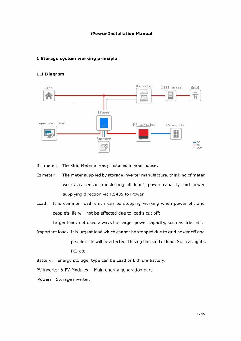
1.1 Diagram
Bill meter: The Grid Meter already installed in your house.
Ez meter: The meter supplied by storage inverter manufacture, this kind of meter
works as sensor transferring all load‟s power capacity and power
supplying direction via RS485 to iPower
Load: It is common load which can be stopping working when power off, and
people‟s life will not be effected due to load‟s cut off;
Larger load: not used always but larger power capacity, such as drier etc.
Important load:It is urgent load which cannot be stopped due to grid power off and
people‟s life will be affected if losing this kind of load. Such as lights,
PC, etc.
Battery: Energy storage, type can be Lead or Lithium battery.
PV inverter & PV Modules: Main energy generation part.
iPower: Storage inverter.
2 / 15
1.2 System working energy direction
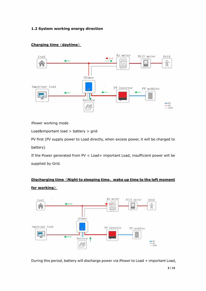
Charging time(daytime)
iPower working mode
Load&important load > battery > grid
PV first (PV supply power to Load directly, when excess power, it will be charged to
battery)
If the Power generated from PV < Load+ important Load, insufficient power will be
supplied by Grid.
Discharging time(Night to sleeping time、wake up time to the left moment
for working)
During this period, battery will discharge power via iPower to Load + important Load,
3 / 15
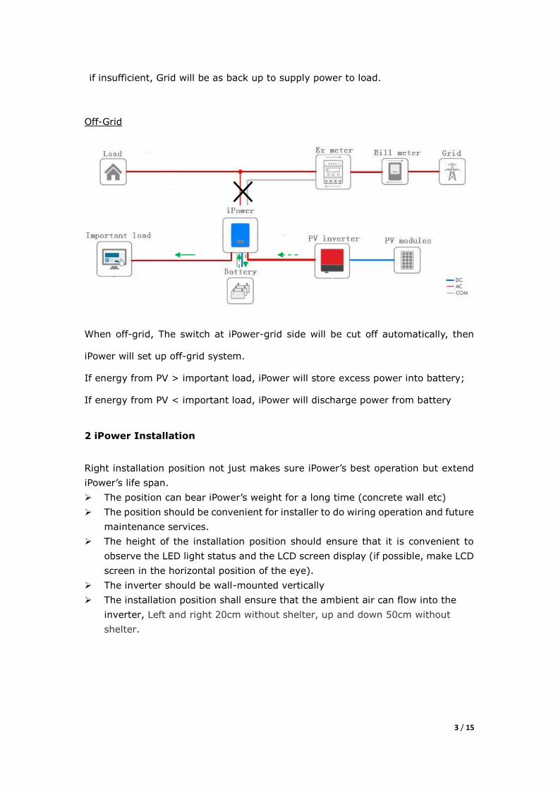
if insufficient, Grid will be as back up to supply power to load.
Off-Grid
When off-grid, The switch at iPower-grid side will be cut off automatically, then
iPower will set up off-grid system.
If energy from PV > important load, iPower will store excess power into battery;
If energy from PV < important load, iPower will discharge power from battery
2 iPower Installation
Right installation position not just makes sure iPower‟s best operation but extend
iPower‟s life span.
The position can bear iPower‟s weight for a long time (concrete wall etc)
The position should be convenient for installer to do wiring operation and future
maintenance services.
The height of the installation position should ensure that it is convenient to
observe the LED light status and the LCD screen display (if possible, make LCD
screen in the horizontal position of the eye).
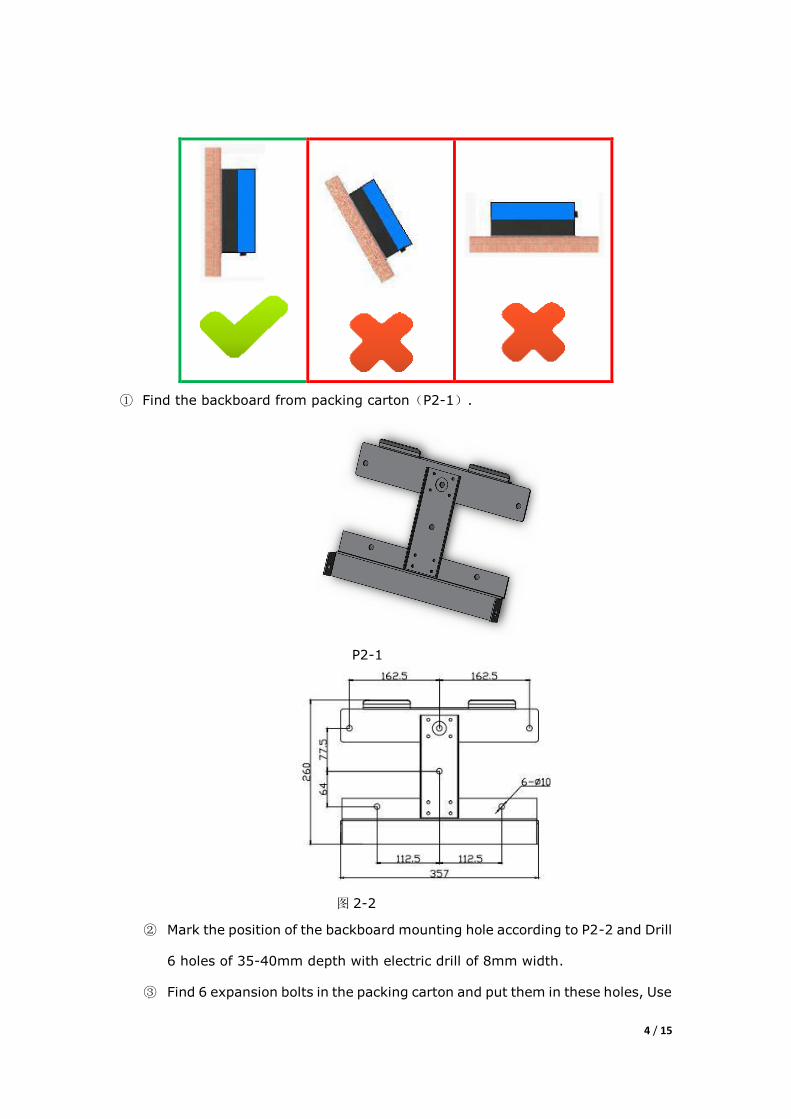
The inverter should be wall-mounted vertically
The installation position shall ensure that the ambient air can flow into the
inverter, Left and right 20cm without shelter, up and down 50cm without
shelter.
4 / 15
① Find the backboard from packing carton(P2-1).
P2-1
图 2-2
② Mark the position of the backboard mounting hole according to P2-2 and Drill
6 holes of 35-40mm depth with electric drill of 8mm width.
③ Find 6 expansion bolts in the packing carton and put them in these holes, Use
5 / 15
an electric screwdriver to tighten these bolts then fix the backboard of the
inverter.
④ Hang the inverter on the backboard slowly. Match and insert the inverter into
the hole, fixing the mounting hole on the side of the backboard with bolts and
ensure the inverter is installed firmly.
3 System set up
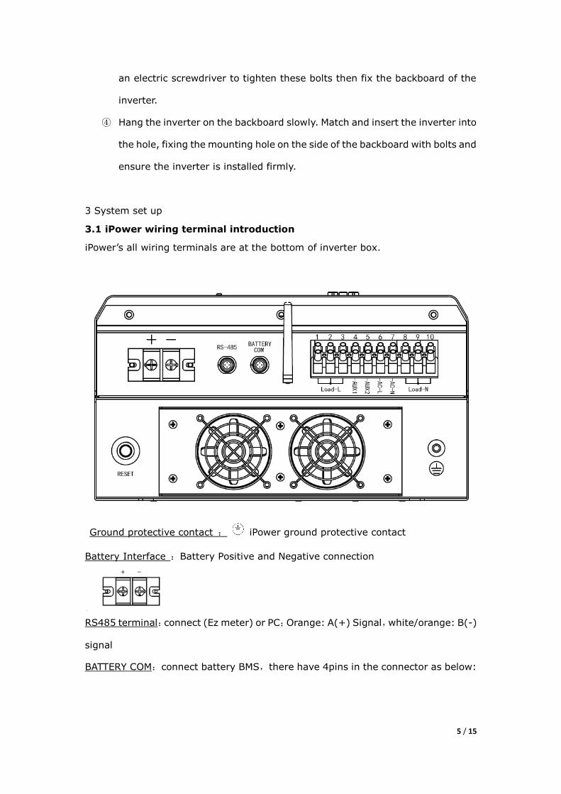
3.1 iPower wiring terminal introduction
iPower‟s all wiring terminals are at the bottom of inverter box.
Ground protective contact : iPower ground protective contact
Battery Interface :Battery Positive and Negative connection
RS485 terminal:connect (Ez meter) or PC;Orange: A(+) Signal,white/orange: B(-)
signal
BATTERY COM:connect battery BMS,there have 4pins in the connector as below:
6 / 15
Please confirm communication interface type of BMS Prior to connect, interface pins
are defined as follows:
1) RS-485:“2”pin B(-),“3”pin GND, “4”pin A(+);
2) RS-232: “2”pin TX,“3”pin RX, “4”pin GND;
3) CAN: “2”pin CANL,“3”pin CANH,“4”pin GND。
AC Terminal Row : LOAD-L and LOAD-N connect important load and PV inverter;
AC-L and AC-N connect grid;AUX1 and AUX2 are output dry contact。Each terminal
can be connected to Max. Wire cross-sectional area is 10mm2.
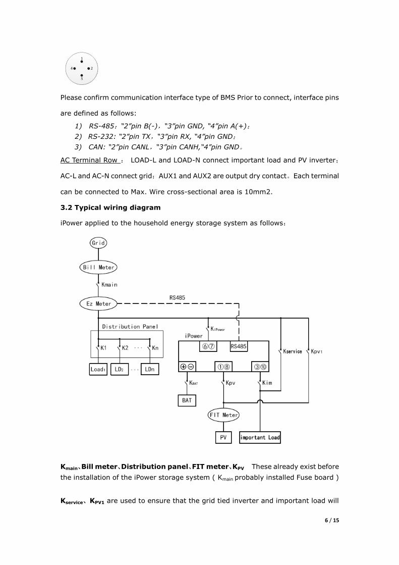
3.2 Typical wiring diagram
iPower applied to the household energy storage system as follows:
Kmain、Bill meter、Distribution panel、FIT meter、KPV These already exist before
the installation of the iPower storage system ( Kmain probably installed Fuse board )
Kservice、KPV1 are used to ensure that the grid tied inverter and important load will
7 / 15
still run reliably when you upgrade the storage system, Kservice、KPV1 is in the
„ disconnected‟ state when the storage system is in normal operation mode.
Kipower Max. Power lie on the following:
P1 = important load power + max charge power,
P2 = max PV power,
P3 = max discharge power.
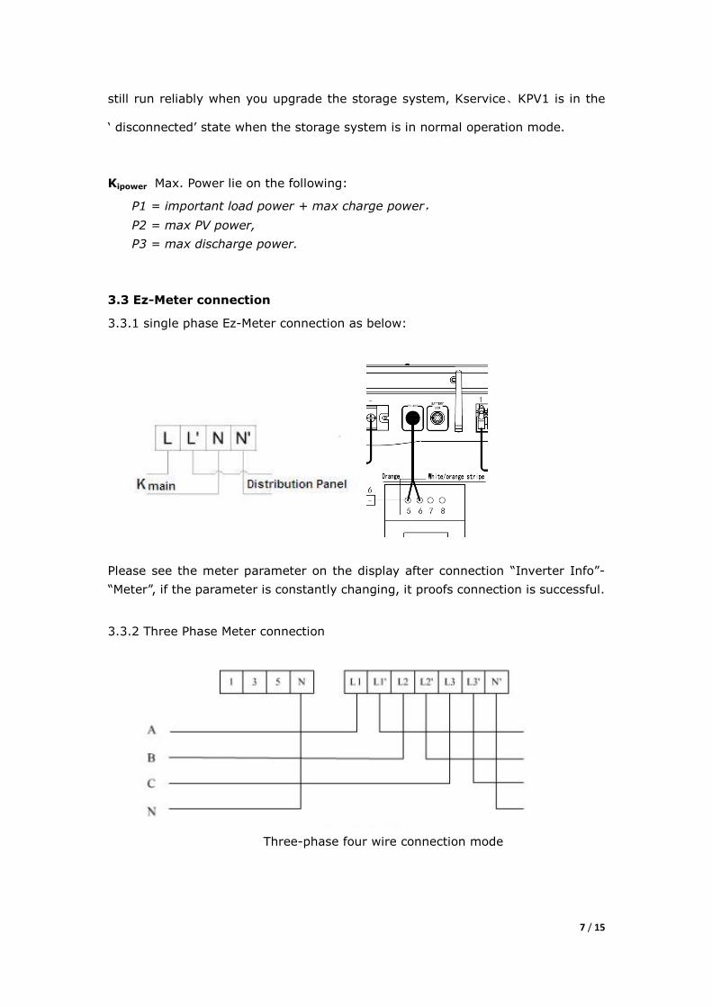
3.3 Ez-Meter connection
3.3.1 single phase Ez-Meter connection as below:
Please see the meter parameter on the display after connection “Inverter Info”-
“Meter”, if the parameter is constantly changing, it proofs connection is successful.
3.3.2 Three Phase Meter connection
Three-phase four wire connection mode
8 / 15
Three-phase three wire connection mode
RS485 connection
3.3.3 After Meter wiring connection , pls check “ inverter info- meter information”
from LCD display screen, if the meter reading is changing quickly, it means you
successfully make it connected. Otherwise, pls check if your connection is right.
3.4 Ground wire connection
Connect the PE to the Figure 3-1 , ground wire cross-sectional area is 6mm2, ,
terminal is OT5.5-6。
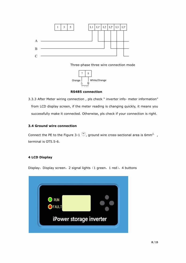
4 LCD Display
Display:Display screen,2 signal lights(1 green,1 red),4 buttons
White/Orange Orange
9 / 15
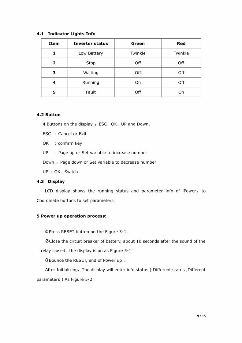
4.1 Indicator Lights Info
Item Inverter status Green Red
1 Low Battery Twinkle Twinkle
2 Stop Off Off
3 Waiting Off Off
4 Running On Off
5 Fault Off On
4.2 Button
4 Buttons on the display :ESC、OK、UP and Down。
ESC : Cancel or Exit
OK : confirm key
UP :Page up or Set variable to increase number
Down :Page down or Set variable to decrease number
UP + OK:Switch
4.3 Display
LCD display shows the running status and parameter info of iPower, to
Coordinate buttons to set parameters
5 Power up operation process:
○1 Press RESET button on the Figure 3-1;
○2 Close the circuit breaker of battery, about 10 seconds after the sound of the
relay closed,the display is on as Figure 5-1
○3 Bounce the RESET, end of Power up 。
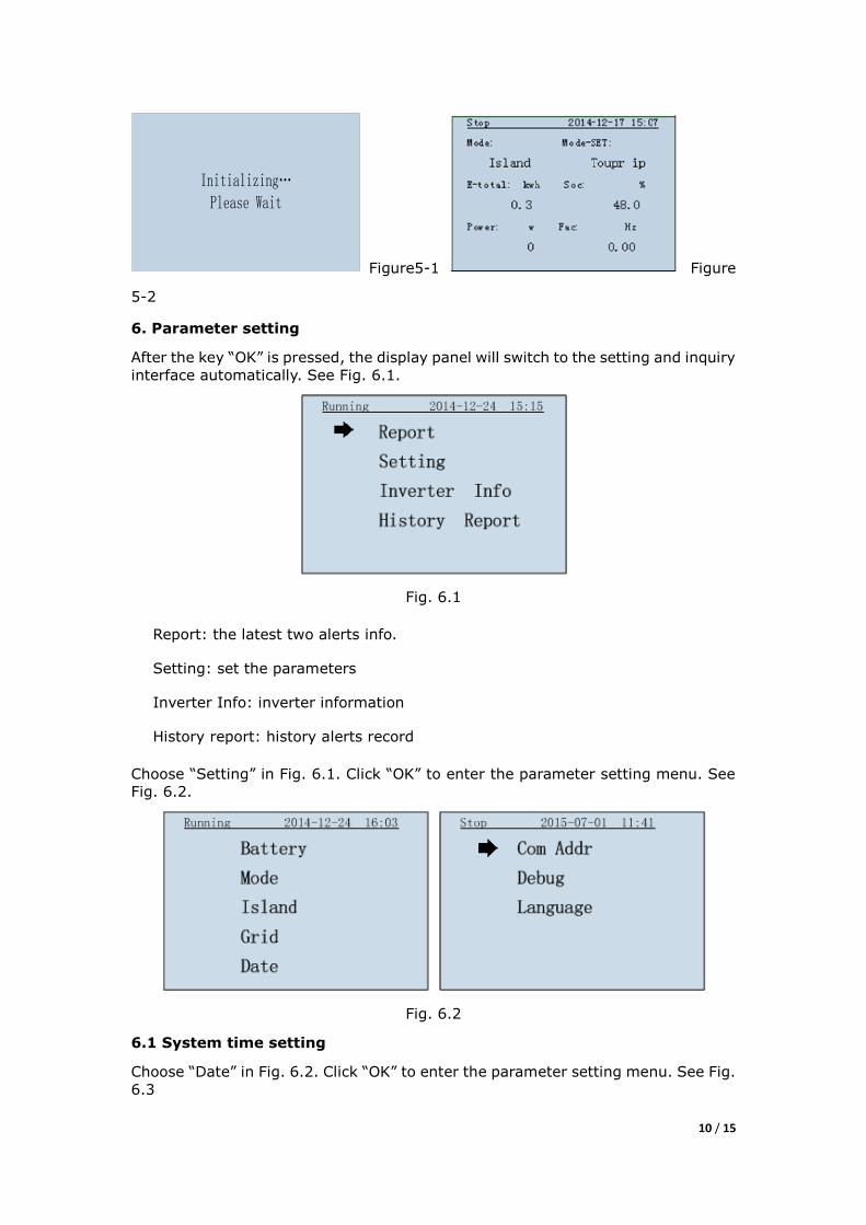
After Initializing,The display will enter info status ( Different status ,Different
parameters ) As Figure 5-2.
10 / 15
Initializing…Please Wait
Figure5-1 Figure
5-2
6. Parameter setting
After the key “OK” is pressed, the display panel will switch to the setting and inquiry
interface automatically. See Fig. 6.1.
Fig. 6.1
Report: the latest two alerts info.
Setting: set the parameters
Inverter Info: inverter information
History report: history alerts record
Choose “Setting” in Fig. 6.1. Click “OK” to enter the parameter setting menu. See
Fig. 6.2.
Fig. 6.2
6.1 System time setting
Choose “Date” in Fig. 6.2. Click “OK” to enter the parameter setting menu. See Fig.
6.3
11 / 15
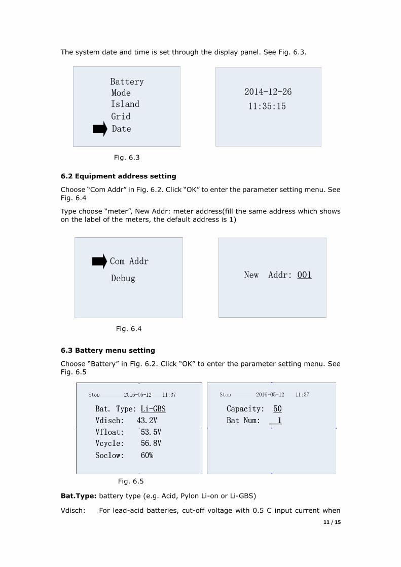
The system date and time is set through the display panel. See Fig. 6.3.
BatteryModeIsland
Grid
Date
Fig. 6.3
2014-12-26
11:35:15
6.2 Equipment address setting
Choose “Com Addr” in Fig. 6.2. Click “OK” to enter the parameter setting menu. See
Fig. 6.4
Type choose “meter”, New Addr: meter address(fill the same address which shows
on the label of the meters, the default address is 1)
Com Addr
Debug
Fig. 6.4
New Addr: 001
6.3 Battery menu setting
Choose “Battery” in Fig. 6.2. Click “OK” to enter the parameter setting menu. See
Fig. 6.5
Fig. 6.5
Bat.Type: battery type (e.g. Acid, Pylon Li-on or Li-GBS)
Vdisch: For lead-acid batteries, cut-off voltage with 0.5 C input current when
12 / 15
discharge to Soclow
For lithium-ion batteries, input the discharge voltage.
Vfloat: Float charging voltage (lead-acid battery needs to be set only)
Vcycle: average charge voltage
Soclow: The battery discharge SOC limit
Capacity: battery capacity (shall be set according to the connected battery
information. For instance, if the battery is 200Ah, 200 shall be set).
Bat Num: number of the batteries (lead-acid battery needs to be set only)
Note 1: All of the lead-acid battery type should be supported by iPower
Note 2 : Battery parameters can be changed only when the storage inverter
is not running. Otherwise, the change is invalid.
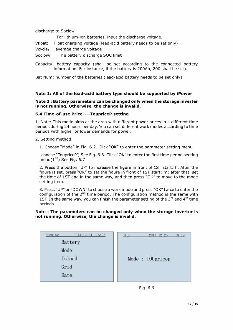
6.4 Time-of-use Price----ToupriceP setting
1. Note: This mode aims at the area with different power prices in 4 different time
periods during 24 hours per day. You can set different work modes according to time
periods with higher or lower demands for power.
2. Setting method:
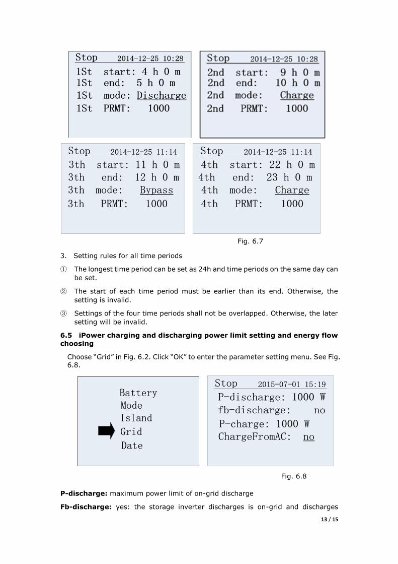
1. Choose “Mode” in Fig. 6.2. Click “OK” to enter the parameter setting menu.
choose “ToupriceP”, See Fig. 6.6. Click “OK” to enter the first time period seeting
menu(1ST) See Fig. 6.7
2. Press the button “UP” to increase the figure in front of 1ST start: h. After the
figure is set, press “OK” to set the figure in front of 1ST start: m; after that, set
the time of 1ST end in the same way, and then press “OK” to move to the mode
setting item.
3. Press “UP” or “DOWN” to choose a work mode and press “OK” twice to enter the
configuration of the 2nd time period. The configuration method is the same with
1ST. In the same way, you can finish the parameter setting of the 3rd and 4th time
periods.
Note : The parameters can be changed only when the storage inverter is
not running. Otherwise, the change is invalid.
Fig. 6.6
13 / 15
Stop 2014-12-25 11:14
3th start: 11 h 0 m3th end: 12 h 0 m3th mode: Bypass
3th PRMT: 1000
Stop 2014-12-25 11:14
4th start: 22 h 0 m4th end: 23 h 0 m4th mode: Charge
4th PRMT: 1000
Fig. 6.7
3. Setting rules for all time periods
① The longest time period can be set as 24h and time periods on the same day can
be set.
② The start of each time period must be earlier than its end. Otherwise, the
setting is invalid.
③ Settings of the four time periods shall not be overlapped. Otherwise, the later
setting will be invalid.
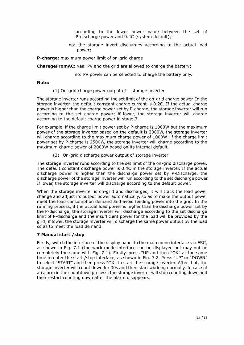
6.5 iPower charging and discharging power limit setting and energy flow
choosing
Choose “Grid” in Fig. 6.2. Click “OK” to enter the parameter setting menu. See Fig.
6.8.
BatteryModeIsland
Grid
Date
Stop 2015-07-01 15:19
P-discharge: 1000 W fb-discharge: no
P-charge: 1000 WChargeFromAC: no
Fig. 6.8
P-discharge: maximum power limit of on-grid discharge
Fb-discharge: yes: the storage inverter discharges is on-grid and discharges
14 / 15
according to the lower power value between the set of
P-discharge power and 0.4C (system default);
no: the storage invert discharges according to the actual load
power;
P-charge: maximum power limit of on-grid charge
CharegeFromAC: yes: PV and the grid are allowed to charge the battery;
no: PV power can be selected to charge the battery only.
Note:
(1) On-grid charge power output of storage inverter
The storage inverter runs according the set limit of the on-grid charge power. In the
storage inverter, the default constant charge current is 0.2C. If the actual charge
power is higher than the charge power set by P-charge, the storage inverter will run
according to the set charge power; if lower, the storage inverter will charge
according to the default charge power in stage 3.
For example, if the charge limit power set by P-charge is 1000W but the maximum
power of the storage inverter based on the default is 2000W, the storage inverter
will charge according to the maximum charge power of 1000W; if the charge limit
power set by P-charge is 2500W, the storage inverter will charge according to the
maximum charge power of 2000W based on its internal default.
(2) On-grid discharge power output of storage inverter
The storage inverter runs according to the set limit of the on-grid discharge power.
The default constant discharge power is 0.4C in the storage inverter. If the actual
discharge power is higher than the discharge power set by P-Discharge, the
discharge power of the storage inverter will run according to the set discharge power.
If lower, the storage inverter will discharge according to the default power.
When the storage inverter is on-grid and discharges, it will track the load power
change and adjust its output power automatically, so as to make the output power
meet the load consumption demand and avoid feeding power into the grid. In the
running process, if the actual load power is higher than he discharge power set by
the P-discharge, the storage inverter will discharge according to the set discharge
limit of P-discharge and the insufficient power for the load will be provided by the
grid; if lower, the storage inverter will discharge the same power output by the load
so as to meet the load demand.
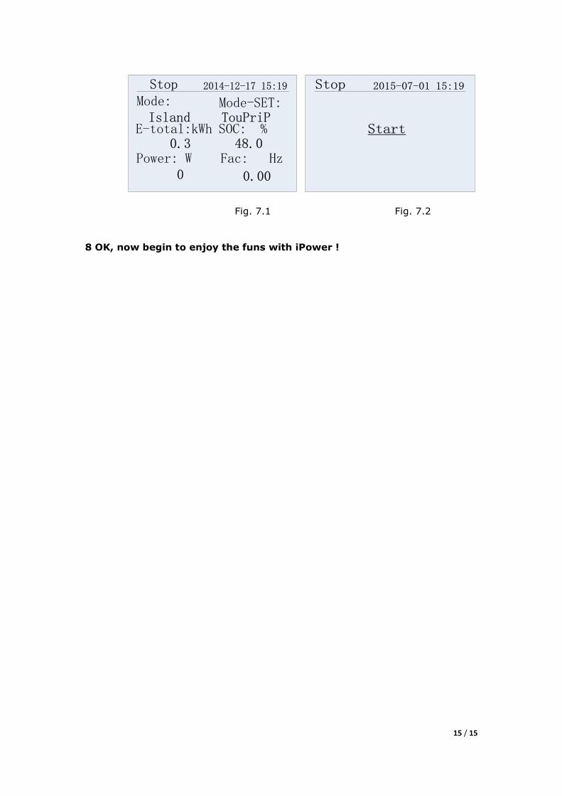
7 Manual start /stop
Firstly, switch the interface of the display panel to the main menu interface via ESC,
as shown in Fig. 7.1 (the work mode interface can be displayed but may not be
completely the same with Fig. 7.1). Firstly, press “UP and then “OK” at the same
time to enter the start /stop interface, as shown in Fig. 7.2. Press “UP” or “DOWN”
to select “START” and then press “OK” to start the storage inverter. After that, the
storage inverter will count down for 30s and then start working normally. In case of
an alarm in the countdown process, the storage inverter will stop counting down and
then restart counting down after the alarm disappears.
15 / 15
Stop 2014-12-17 15:19
Mode: Mode-SET:Island
E-total:kWh
Power: W
SOC: %
Fac: Hz
TouPriP
0.3 48.0
0 0.00
Stop 2015-07-01 15:19
Start
Fig. 7.1 Fig. 7.2
8 OK, now begin to enjoy the funs with iPower !