ips debugging and evaluation - cei-lab.github.io
TRANSCRIPT

IPS Debugging and Evaluation
https://ajaywhiz.wordpress.com/2010/02/23/software-development-life-cycle-emotions/

2
Specification and Evaluation
• Sensitivity of IR sensors• Output vs. distance• SNR• Resistance to ambient light
• Sensitivity of microphone• Output vs. distance
• Bandwidth of communication• Battery life time
• (Under specific circumstance)• Computation speed/memory
• Filters…• Encoders…• etc. The One-ders, 2017

3
Specification and Evaluation
• FFT• What is the Q of your filter?
• Search• How long does it take to find a path?
• Worst case and best case scenarios• How does your implementation scale in time and
memory with the size of the maze?
• Speed/power of your servos• Payload capability

4
Evaluation
• Straight line velocity• Turn speed, turn radius• Reliability of grid traversal (straight/turn)• Battery life time
• Straight line test
Standards• Help you compare different systems• …not that common in robotics
• To help; be thorough in your evaluation, report negative results and reliability tests

MeanMax/Min
5
How to convey the information?
• Tables (max/min values)• Graphs
• with error bars• Color maps
• NB: BW printers/color blind people
Standard deviationRaw

6
Debugging Intelligent Physical SystemsDebugging is more complex than ever!
• Electronics
• Software
• Mechanics
• Multiple connected devices
• Simulation
Worst bugs are intermittent
→ Apply a methodical and documented search

7
Debugging Intelligent Physical SystemsMARK I Computer, Harvard, by Howard Aiken in 1944

8
Debugging Intelligent Physical SystemsAdmiral Grace Hopper, 1906-1992MARK I Computer, Harvard, by Howard Aiken in 1944
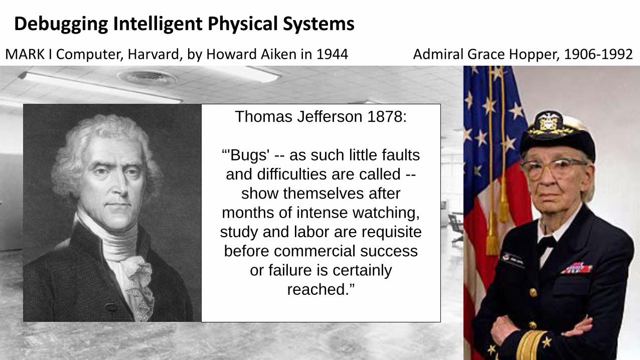
9
Debugging Intelligent Physical SystemsAdmiral Grace Hopper, 1906-1992MARK I Computer, Harvard, by Howard Aiken in 1944
Thomas Jefferson 1878:
“'Bugs' -- as such little faults and difficulties are called --
show themselves after months of intense watching, study and labor are requisite before commercial success
or failure is certainly reached.”

Developing Your System
• Bottom-up development
• Unit testing
• Faster initial progress
• Top-down development
• Implement every thing to begin with
• Add dummy functions as placeholders
• Leads to more modular products
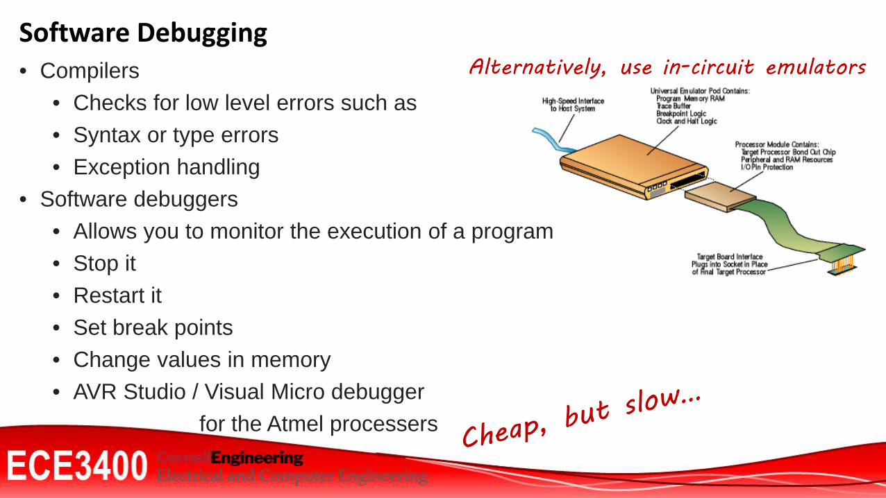
Alternatively, use in-circuit emulatorsSoftware Debugging• Compilers
• Checks for low level errors such as• Syntax or type errors• Exception handling
• Software debuggers• Allows you to monitor the execution of a program• Stop it• Restart it• Set break points• Change values in memory• AVR Studio / Visual Micro debugger
for the Atmel processers

12
Browsing for help online

• Always test circuit beforehand!• Add test points • Make circuit dividers
• Visual inspection• Go/Nogo• Test jig• Automated Test Equipment
14
PCB Debugging
time, price, thoroughness

• Typically related to friction or jamming• Broken teeth/dirt in gears• Broken axels• Fallen/obscured sensors• Broken wiresErrors leads to symptoms:• Bad sensor values• Slow/biased movement• Jamming may cause power surges and reset conditions• Make a test jig for the robot
15
Mechanical Bugs?

Map Your System , then describe your interfaces!
PWM [0-5V]f [20Hz]DC [1.1-1.9ms]
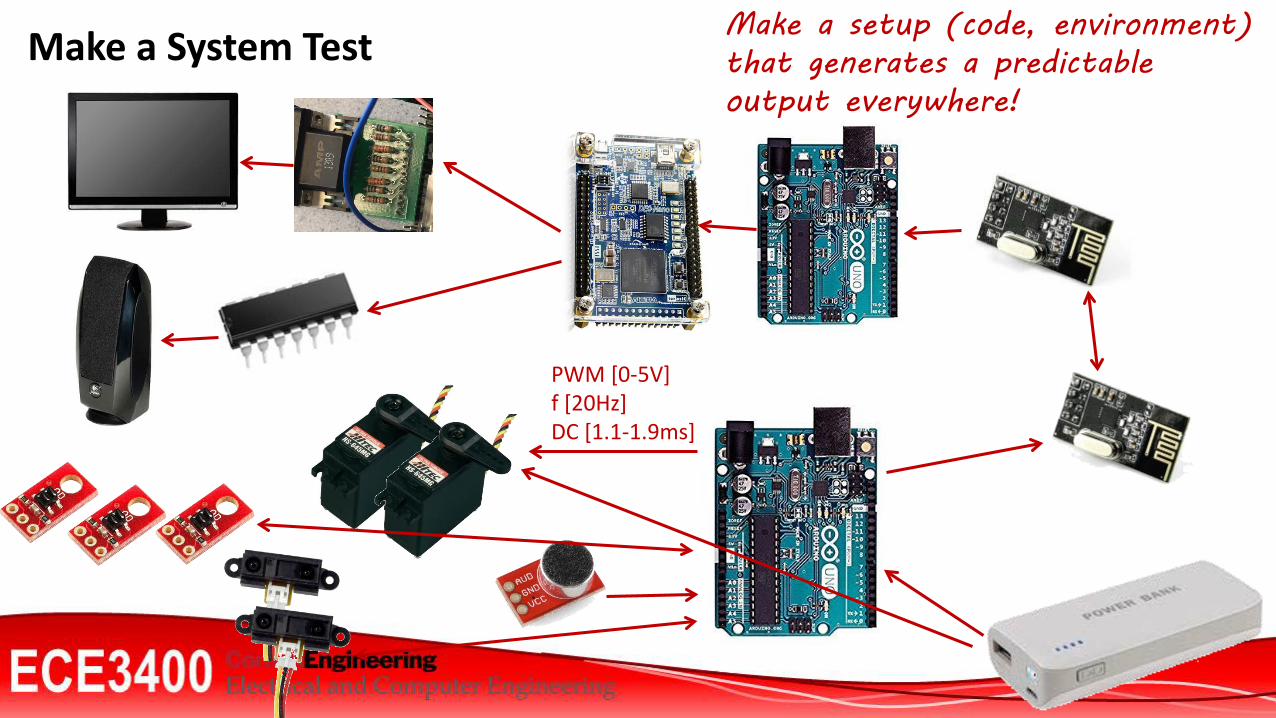
Make a System Test
PWM [0-5V]f [20Hz]DC [1.1-1.9ms]
Make a setup (code, environment) that generates a predictable output everywhere!

Debugging IPS• STEP 1: Reproduce the symptom!
• STEP 2: Hunt down the bug
• Brute force debugging
• Problem simplification
• Backtracking (start from problem)
• Tracing or print debugging
• Binary Search
• Scientific Method: Form hypothesis and test it
• Bug clustering
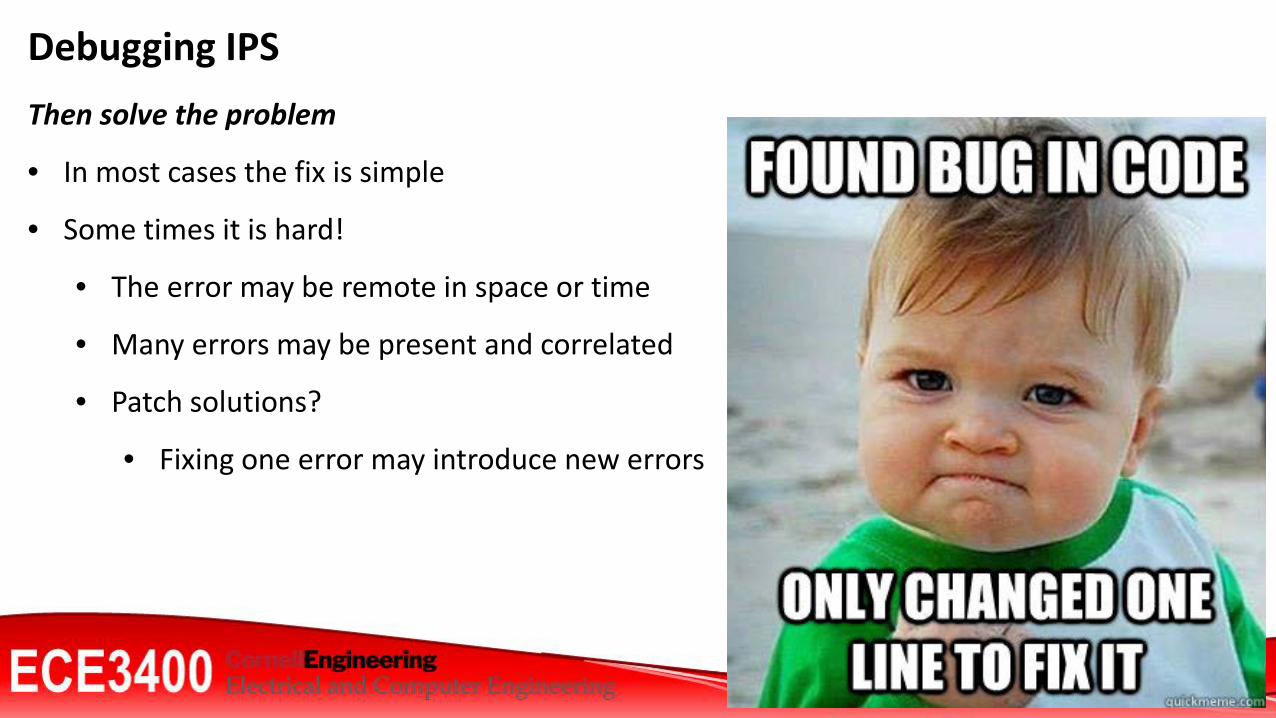
Debugging IPSThen solve the problem
• In most cases the fix is simple
• Some times it is hard!
• The error may be remote in space or time
• Many errors may be present and correlated
• Patch solutions?
• Fixing one error may introduce new errors
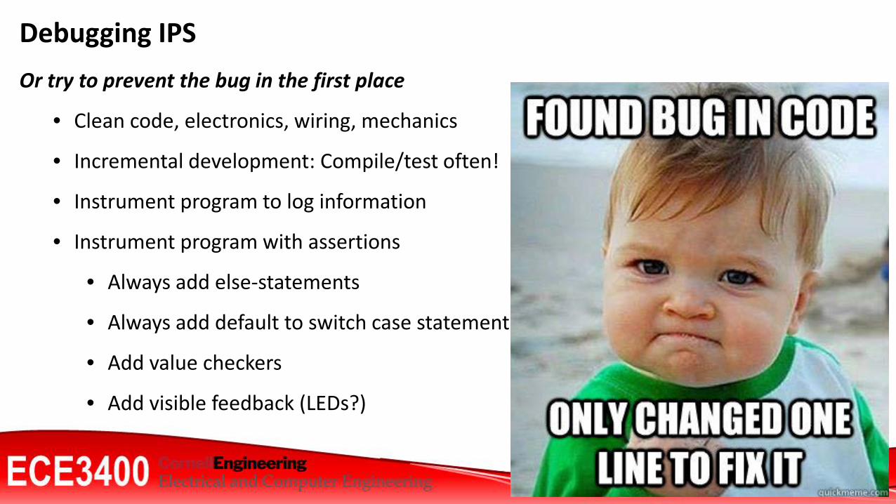
Debugging IPSOr try to prevent the bug in the first place
• Clean code, electronics, wiring, mechanics
• Incremental development: Compile/test often!
• Instrument program to log information
• Instrument program with assertions
• Always add else-statements
• Always add default to switch case statements
• Add value checkers
• Add visible feedback (LEDs?)

• It appears hopeless, but there is a logical structure in there. The evidence may be obscure, but consistent in pointing to the guilty element.
• Don't panic -- be methodical. Often the TA is able to do this, and they don't know more about your code than you do.
• Discuss it with a team mate• Sleep on it!
21
Mindset

• Intuition and hunches are great— you just have to test them out. When a hunch and a fact collide, the fact wins.
• Don't look for complex explanations. Even the simplest omission or typo can lead to very weird behavior.
• The clue to what is wrong is in the values of your variables.• Be systematic and persistent. The bug is not moving around in your system, trying to
trick or evade you. It is just sitting in one place, doing the wrong thing in the same way every time.
• If your code was working a minute ago, but now it doesn't— what was the last thing you changed?
• Do not change your code haphazardly trying to track down a bug. • Fix bugs immediately (even if they’re not the original bug you were looking for, errors
may be correlated).
22
Mindset
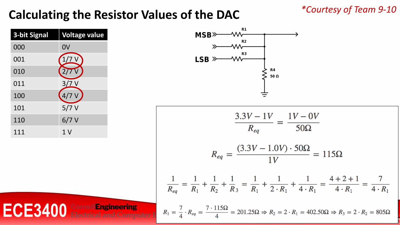
3-bit Signal Voltage value
000 0V
001 1/7 V
010 2/7 V
011 3/7 V
100 4/7 V
101 5/7 V
110 6/7 V
111 1 V
23
Calculating the Resistor Values of the DAC *Courtesy of Team 9-10
24
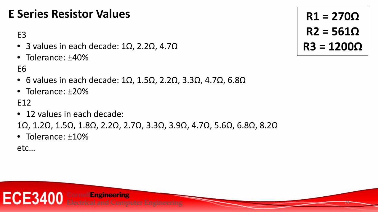
E Series Resistor Values
E3• 3 values in each decade: 1Ω, 2.2Ω, 4.7Ω • Tolerance: ±40%E6 • 6 values in each decade: 1Ω, 1.5Ω, 2.2Ω, 3.3Ω, 4.7Ω, 6.8Ω• Tolerance: ±20%E12 • 12 values in each decade: 1Ω, 1.2Ω, 1.5Ω, 1.8Ω, 2.2Ω, 2.7Ω, 3.3Ω, 3.9Ω, 4.7Ω, 5.6Ω, 6.8Ω, 8.2Ω • Tolerance: ±10%etc…
R1 = 270ΩR2 = 561Ω
R3 = 1200Ω
25
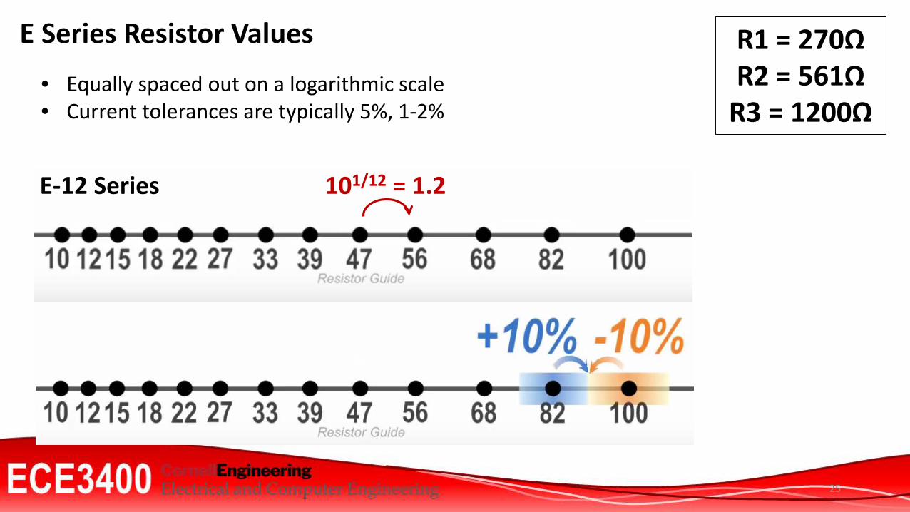
E Series Resistor Values
• Equally spaced out on a logarithmic scale• Current tolerances are typically 5%, 1-2%
E-12 Series 101/12 = 1.2
R1 = 270ΩR2 = 561Ω
R3 = 1200Ω

3-bit Signal Voltage value
000 0V
001 1/7 V
010 2/7 V
011 3/7 V
100 4/7 V
101 5/7 V
110 6/7 V
111 1 V
Calculating the Resistor Values of the DAC R1 = 270ΩR2 = 561Ω
R3 = 1200Ω
0X1 → 3.3V ∙ [50Ω||R1] / [R3 + (50Ω||R1)] = 3.3V ∙ 42.2Ω /(1200Ω+42.2Ω) = 0.11V
3-bit Signal Voltage value
000 0V
001 0.1428 V
010 0.2857 V
011 0.4285 V
100 0.5714 V
101 0.7142 V
110 0.8571 V
111 1 V
Tristate pins:
• Set pins to inputs!
X01 → 3.3V ∙ [50Ω||R2] / [R3 + (50Ω||R2)] = 3.3V ∙ 46.0Ω /(1200Ω+46.0Ω) = 0.12V
XX1 → 3.3V ∙ 50Ω / [R3 + 50Ω] = 3.3V ∙ 50Ω /(1200Ω+50Ω) = 0.132V

Logistics:
• Next week
• Ethics!
• Lectures and Homework

28
Class website: https://cei-lab.github.io/ece3400/Piazza: https://piazza.com/cornell/fall2017/ece3400/home