ir imaging for machine vision and process control
TRANSCRIPT

IR imaging for machine vision and process control
Jason Styron, FLIR, 25 Esquire Rd., North Billerica, MA 01862
ABSTRACT
This paper discusses the technology behind infrared as a form of non-visible imaging. Discussions will cover detector technology, camera platforms, software, software analytics, and applications. The purpose of this presentation is to highlight the use of IR technology for conventional machine vision applications. Today we will cover the basics of IR. Discuss the different detectors that are used to sense IR energy. Clarify the different types of imaging. Define what a Smart Camera is, in regards to a thermal imager. Demonstrate some Non-temperature applications in the recycling industry, pulp and paper industry, and automotive industry. We will also discuss the difference between qualitative and quantitative thermal imaging, which will lead us into temperature measurement applications.
1. INTRODUCTION
Infrared energy lies just past the visible spectrum of light that everyone is familiar with in our everyday lives. Within the IR spectrum, manufacturer’s like FLIR disseminate the “bands” into short-wave (SW), mid-wave (MW), and long-wave (LW) camera systems, see Figure 1.
Figure 1. The electromagnetic spectrum and the three infrared bands commonly used for machine vision and process control.
Infrared energy being part of the electromagnetic spectrum behaves similarly to visible light. It travels through space at the speed of light and can be reflected, refracted, absorbed, and emitted. The wavelength of IR energy is about an order of magnitude longer than visible light, between 0.7 and 1000 µm (millionths of a meter). A comparison of typical visible and infrared images is shown in Figure 2.

Figure 2. Examples of typical visible and infrared images.
It is sometimes helpful to understand where various detector technologies fall within the electromagnetic spectrum, shown in Figure 3.
Figure 3. Different detector materials are sensitive in different parts of the electromagnetic spectrum.
This will help in deciding what detector may be best suited for the application. It will also help to understand the terminology, like InGaAs - “in-gas” - Indium gallium arsenide; or InSb - “ins-bee” – Indium Antimonite; or QWIP – “quip” - (Quantum Well Infrared Photon detector); MCT – Mer-Cad - (Mercury Cadmium Telluride); or microbolometer uncooled, LW.
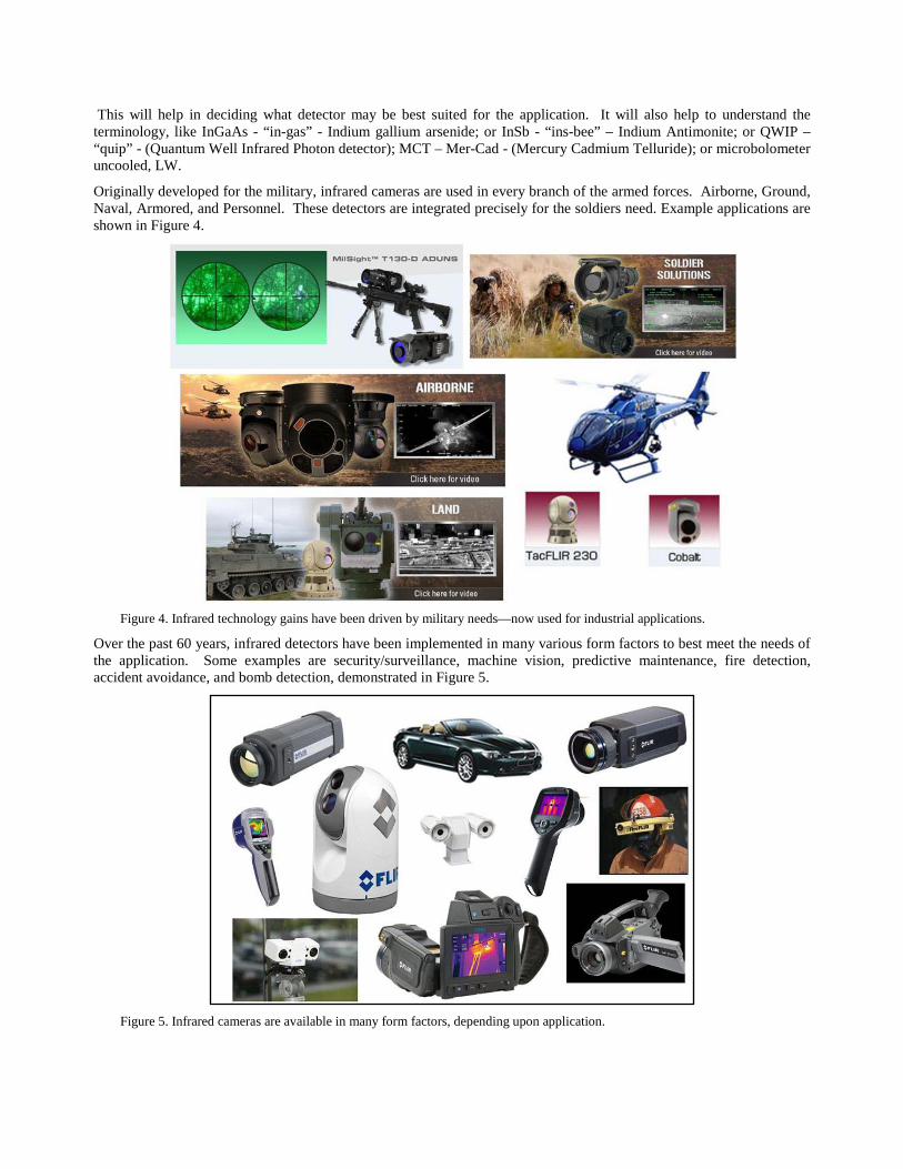
Originally developed for the military, infrared cameras are used in every branch of the armed forces. Airborne, Ground, Naval, Armored, and Personnel. These detectors are integrated precisely for the soldiers need. Example applications are shown in Figure 4.
Figure 4. Infrared technology gains have been driven by military needs—now used for industrial applications.
Over the past 60 years, infrared detectors have been implemented in many various form factors to best meet the needs of the application. Some examples are security/surveillance, machine vision, predictive maintenance, fire detection, accident avoidance, and bomb detection, demonstrated in Figure 5.
Figure 5. Infrared cameras are available in many form factors, depending upon application.
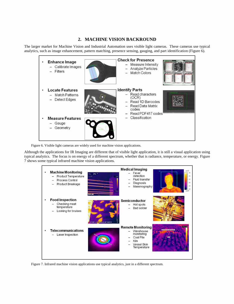
2. MACHINE VISION BACKROUND The larger market for Machine Vision and Industrial Automation uses visible light cameras. These cameras use typical analytics, such as image enhancement, pattern matching, presence sensing, gauging, and part identification (Figure 6).
Figure 6. Visible light cameras are widely used for machine vision applications.
Although the applications for IR Imaging are different that of visible light application, it is still a visual application using typical analytics. The focus is on energy of a different spectrum, whether that is radiance, temperature, or energy. Figure 7 shows some typical infrared machine vision applications.
Figure 7. Infrared machine vision applications use typical analytics, just in a different spectrum.

3. MACHINE VISIION AND PROCESS CONTROL APPLICATIOINS We thought it would help understand the two types of thermal imaging. Qualitative and Quantitative. At a higher level, you can think of qualitative thermal imaging as trying to see a target, like in the military. The military would use qualitative imaging to find bad guys hiding in the dark. They do not care how hot they are, they just want to know if someone or something is there. This is demonstrated in Figure 8.
Figure 8. Qualitative versus quantitative imaging.
Figure 8(a) is a visible image of a torpedo transfer car that is used in the steel industry.
Figure 8(b): This thermal image is taken with an uncooled long wave camera and as you can see, it displays varying thermal patterns. The colors are scaled from white, hot to black, cold. This is a qualitative image. We can “see” the
information, but cannot determine the magnitude of the severity. For some machine vision applications, this is quite acceptable. True temperature measurement is not necessary. We can “see” different temperatures based on the colors (white is hottest, blues are cooler).
Figure 8(c): So, how can measurement help this company? As we now begin to add temperature measurements, operators can assess the variances with much more precise information and ultimately make better decisions about the product or process. This plays extremely well in the machine vision marketplace, when engineers want to understand the quality of a finished product. Operators can not only “see” the thermal patterns, but now measure the differences between various areas to determine the magnitude of the variances.
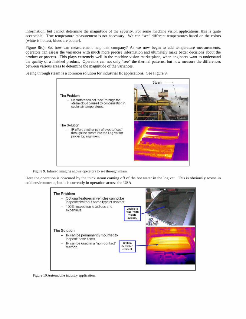
Seeing through steam is a common solution for industrial IR applications. See Figure 9.
Figure 9. Infrared imaging allows operators to see through steam.
Here the operation is obscured by the thick steam coming off of the hot water in the log vat. This is obviously worse in cold environments, but it is currently in operation across the USA.
Figure 10.Automobile industry application.
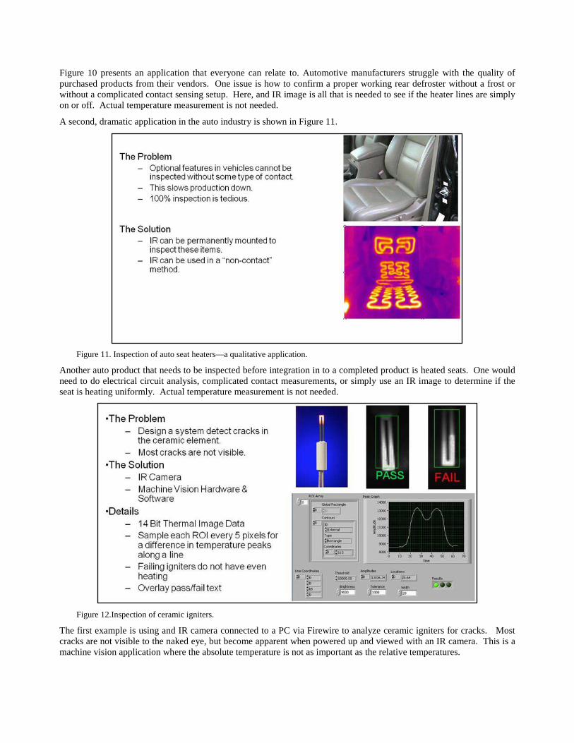
Figure 10 presents an application that everyone can relate to. Automotive manufacturers struggle with the quality of purchased products from their vendors. One issue is how to confirm a proper working rear defroster without a frost or without a complicated contact sensing setup. Here, and IR image is all that is needed to see if the heater lines are simply on or off. Actual temperature measurement is not needed.
A second, dramatic application in the auto industry is shown in Figure 11.
Figure 11. Inspection of auto seat heaters—a qualitative application.
Another auto product that needs to be inspected before integration in to a completed product is heated seats. One would need to do electrical circuit analysis, complicated contact measurements, or simply use an IR image to determine if the seat is heating uniformly. Actual temperature measurement is not needed.
Figure 12.Inspection of ceramic igniters.
The first example is using and IR camera connected to a PC via Firewire to analyze ceramic igniters for cracks. Most cracks are not visible to the naked eye, but become apparent when powered up and viewed with an IR camera. This is a machine vision application where the absolute temperature is not as important as the relative temperatures.

Notice how one leg on the failing part is brighter than the other.
The hardware and software needed include: FLIR IR Camera, NI Software (1394 IMAQ Driver, NI Vision, LabVIEW), NI Hardware CVS 1450, and some custom software. All of the custom software was written using LabVIEW 7.1 and NI’s Vision Development Toolkit.
Originally the customer only wanted qualitative imagery to see through steam to see the extruded product in Figure 13.
Figure 13. Inspection of extruded fibers.
After having a visual interpretation of the application, they realized they now have non-contact temperature measurement that was never before available. They now have individual temperature measurement of each individual extruded strand.
Figure 14. Automation protocols for closed-loop process control.

IR visual data with temperature data can be used for many applications using different industry standards. Quite often, simple data points are needed for closed-loop process control. This data is typically captured using OPC, Ethernet/IP, or ModbusTCP, shown in Figure 14.
For more complex applications where machine vision analytics are needed, GigE Vision and GeniCam make the hardware/software platform much easier.
Smart IR cameras can measure specific data points of your process. Using industrial communication protocols like ModbusTCP and Ethernet/IP, this data can easily become control data points for your automation architecture.
Figure 15 shows a non-contact temperature measurement of synthetic textile material.
.
Figure 15. Textile material inspection.
Temperature can quite often show sub-surface problems in your product. In Figure 16 embedded slag show up as colder regions. The size of these regions can lead to poor quality.
Figure 16. Real-time inspection in I-beam manufacturing.

Real-time inspection of products can allow for the certification and a higher selling price.
Smart IR cameras can measure specific data points of your process. Using industrial communication protocols like ModbusTCP and Ethernet/IP, this data can easily become control data points for your automation architecture.
An off-the-shelf software package, IRControl is available from MoviTHERM1, Irvine, CA.
Figure 17. Real-time inspection of a hot-glue process.
Here non-contact temperature measurement of hot glue is used to determine if adhesive is continuous and applied correctly in real-time.
Multiple cameras can be networked together using Ethernet to create a coordinated monitoring system (Figure 18).
Figure 18. Multiple cameras in an inspection network.
Here the entire circumference of a large tank or vessel can be monitored for hot spots. These hot spots lead users to determine where refractory or other lining systems are weakening or failing.
An off-the-shelf software package, IRMonitor, is available from MoviTHERM1, Irvine, CA.
Ethernet systems can easily be implemented sing wireless or fiber optic for long distance monitoring applications.
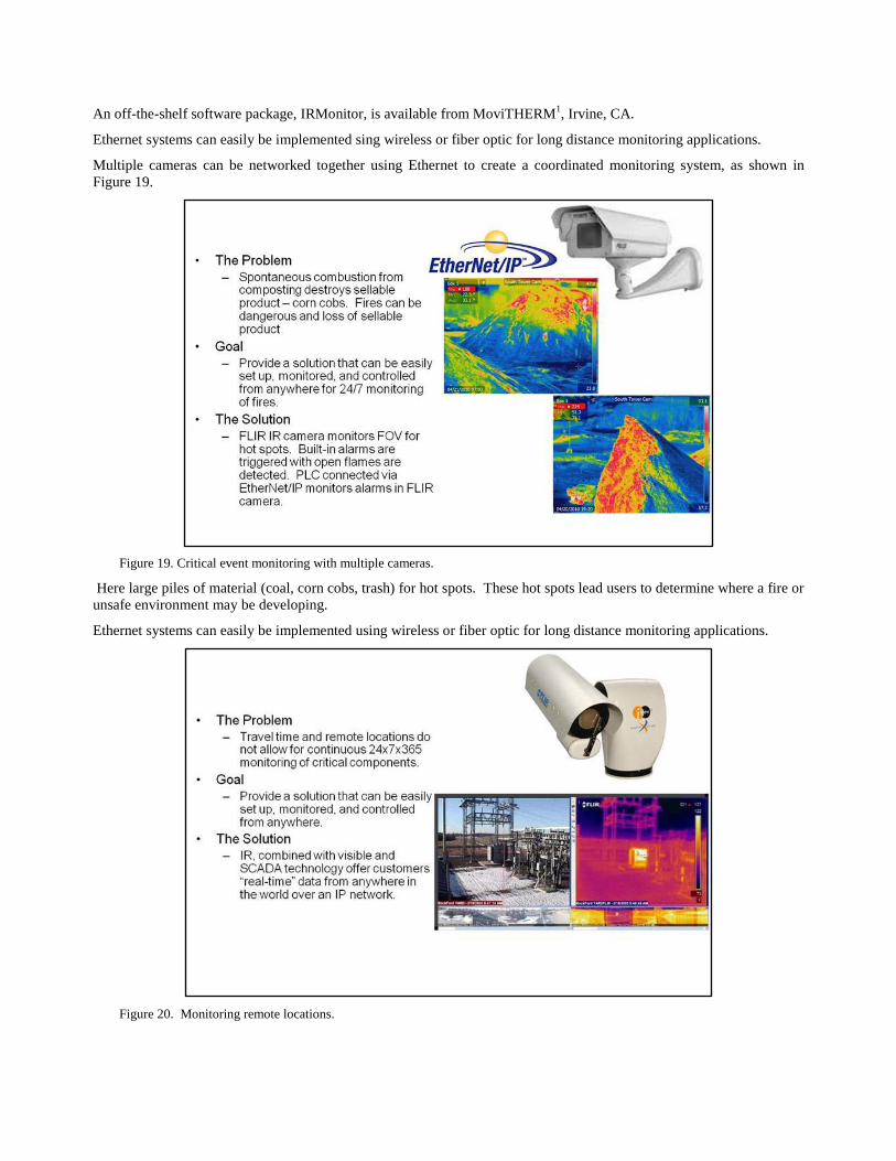
Multiple cameras can be networked together using Ethernet to create a coordinated monitoring system, as shown in Figure 19.
Figure 19. Critical event monitoring with multiple cameras.
Here large piles of material (coal, corn cobs, trash) for hot spots. These hot spots lead users to determine where a fire or unsafe environment may be developing.
Ethernet systems can easily be implemented using wireless or fiber optic for long distance monitoring applications.
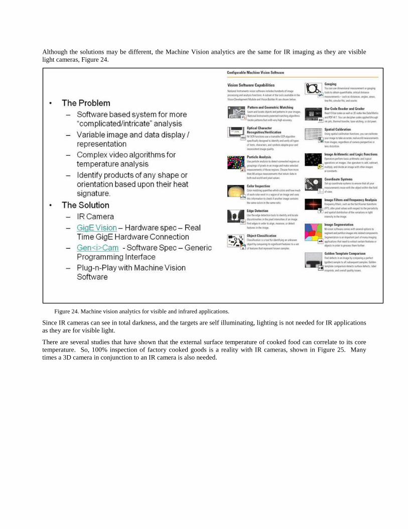
Figure 20. Monitoring remote locations.

Multiple cameras can be networked together using Ethernet to create a coordinated monitoring system. Figure 20 shows that entire electrical substations can be monitored for loose or corroded electrical connections.
Also, you can trend electrical connections for when a component may fail due to temperature, load spikes, or increase in ambient conditions.
Ethernet systems can easily be implemented using wireless or fiber optic for long distance monitoring applications.
Even for smaller substations, multiple cameras can be networked together using Ethernet to create a coordinated monitoring system. In Figure 21 three simple electrical devices are monitored for an overload. A simple PLC can monitor the measured data and alarm when a high temperature is encroached.
Figure 21. Ethernet system application.
Ethernet systems can easily be implemented using wireless or fiber optic for long distance monitoring applications.
A substation is an assemblage of equipment for the purpose of switching and/or changing or regulating the voltage of electricity, as in Figure 222.

Figure 22. Wherever transformers or switchgear are located in a power system, there will probably be a substation.
Machine Vision applications are still based on the visual interpretation of heat. These applications typically call for more complicated and intricate analysis of the image (Figure 23).
Figure 23. GigE Vision and GeniCam are the standards of choice today to bring the hardware and software together.
Although the solutions may be different, the Machine Vision analytics are the same for IR imaging as they are visible light cameras, Figure 24.
Figure 24. Machine vision analytics for visible and infrared applications.
Since IR cameras can see in total darkness, and the targets are self illuminating, lighting is not needed for IR applications as they are for visible light.
There are several studies that have shown that the external surface temperature of cooked food can correlate to its core temperature. So, 100% inspection of factory cooked goods is a reality with IR cameras, shown in Figure 25. Many times a 3D camera in conjunction to an IR camera is also needed.

Figure 25. Example of factory cooked goods.
Figure 26 is a good example of an application where minimal heat is introduced into the product to induce a heat signature.
Figure 26. Minimal heat is required for some applications.

An air pocket then acts as an insulator to keep the heat trapped in the target. This heat anomaly is then easily detected using machine vision analytics.
Figure 27 is a hot glue application where continuity of the application of the glue was in question.
Figure 27. Affordable microbolometer cameras are used in most automation applications.
Visibly the glue is undetectable. Using IR imagery the glue is easily imaged and checked using circular edge detection with machine vision software. The consistency of the glue temperature was also used as a process control data point.
IR cameras can be used to image cold targets as well has hot ones, as shown in Figure 28.
Figure 28. Example of automation with a cold, rather than hot source. It is temperature difference that matters.

Here we used the capability of IR cameras to see through the thin-film white plastic bag used to cover these popular popsicles. No lighting or heat sources are needed to see through the bag. Once and image is provided, software can easily detect the Popsicle count, stick count, and stick placement.
For those who want more than a manual interpretation of a rear defroster window. Figure 29 is an example of how machine vision software can easily automate the inspection process.
Figure 29. Example of complete automated system.
4. CONCLUSION This paper has shown examples of the equipment, software and protocols for implementation of machine vision and process control.
Also discussed were detector technology, camera platforms, software, software analytics, and applications. The presentation highlighted the use of IR technology for conventional machine vision applications. The difference between qualitative and quantitative thermal imaging, was presented, which led into temperature measurement applications. Examples were given of applications in the recycling industry, pulp and paper industry, and automotive industry.
As with visual applications, the uses for IR imagery are boundless.
REFERENCES
[1] MoviTHERM, http://www.movitherm.com. [2] “Electric Utility Systems and Practices,” General Electric Co.; John Wiley and Sons