ir10 / pp10 field indicator and controllers ternal relas ... · pdf fileir10 / pp10 field...
TRANSCRIPT
IR10 / PP10Field Indicator and Controllers
Operating instruction manual OI/IR10-EN Rev. D
External relays: IR10 interposing relay / PP10 latching relayK-TEK Products
IntroductionThis operating instruction manual provides the following infor-mation: – Mounting - see page 5 – Maintenance - see page 5 – Applications - see page 6

2 IR10/PP10 Field Indicator and Controllers | Operating instruction manual
Table of Contents1.0 Introduction ...........................................................................................................................................................3 1.1 Function .........................................................................................................................................................32.0 Mounting ...............................................................................................................................................................4 2.1 General Installations Guidelines ....................................................................................................................43.0 Maintenance .........................................................................................................................................................5 3.1 Safety Instructions .........................................................................................................................................54.0 Applications ..........................................................................................................................................................6 4.1 IR10 Motor or Motor Starter Control ..............................................................................................................6 4.2 PP10 Latching Relay .....................................................................................................................................75.0 Appendix ...............................................................................................................................................................8 5.1 Reed Switch Protection .................................................................................................................................86.0 Warranty ...............................................................................................................................................................9
Operating instruction manual | IR10/PP10 Field Indicator and Controllers 3
1.0 Introduction
The ABB IR10 Interposing Relay (AC or DC Relay) Output Module is designed for use in applications such that certain pro-cess control equipment may require a higher operating current thatn can be supplied by various ABB (or other manufactur-ers’) switch products. The module can be used for applications requiring control of on/off devices such as motors, motor starters, solenoids and alarms. The IR10 consists of printed circuit board mounted relay and three terminal blocks. It is supplied in an explosion proof enclosure (Class 1, Division 1). The unit is generally powered by 120 VAC, although other operating voltages are available. The module accepts one set of DPDT dry contacts as an output (NO and NC contacts).
The ABB PP10 Latching Relay Controller is designed for use in applications requiring control of on / off devices such as motors, motor starters, solenoids and alarms. The Pump-Pak is a control device consisting of a PC board mounted relay and associated components. The PP10 is supplied in an explosion proof enclosure (Class 1, Division 1) and is available with an optional mounting hardware kit. The PP10 is generally powered by 120 VAC, however, other operating voltages are available. The PP10 accepts one set of contact inputs and provides a dry contact input (NO and NC contacts).
1.1 FunctionThe IR10 operates as a simple interposting relay, actuated by an external limit switch. The relay will energize when a closed contact is sensed at the input terminal. When used for a motor, solenoid or alarm function, the input power is supplied to the IR-10 via a DC or AC connection. The input power is isolated from the output contacts. Two IR-10s can be configured to operate four isolated process devices. A circuit can be configured in a “fail-safe” mode such that a power failure will cause a high level alarm.
The PP10 operates as a simple start / stop control circuit, actuated by external limit switches. High or low level operation is selected via a miniature switch located on the circuit board. The on-board relay operates as follows: In the HLO (to empty a tank) position, relay K1 energizes when the high level limit is tripped and then deenergizes when the low level limit is reached. In the LLO (to fill a tank) position, relay K1 energizes when the low level limit is tripped and then deenergizes when the high level limit is reached. In the event of power failure with the relay energized, the PP10 unit will revert back to proper operation after one cycle of the level limit switches.
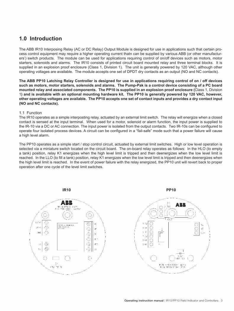
IR10 PP10
4 IR10/PP10 Field Indicator and Controllers | Operating instruction manual
2.0 MountingThe IR10 and PP10 units are generally mounted in an explosion proof enclosure using two 6-32 screws and standoffs. The standoffs are required between the circuit board and enclosure. The units can be mounted in other enclosures, if required.
The following procedure outlines the steps necessary to install the unit.
WARNING! MAKE SURE CIRCUIT IS DEENERGIZED BEFORE INSTALLING THE UNIT!
1. Install conduit and field wiring per NEC requirements. 2. Use the unit schematic below to insure proper electrical connection. Be sure to note the appendix
regarding protection of the relay contacts. Relay contact damage will void the manufacturers war- ranty. The external limit switches used to operate the unit are protected by an integral component on the unit’s circuit board.
3. Once satisfied that all connections are correct, cycle the upper and lower limit switches as in normal operation. The relay should pull-in or drop-out as per the explanation of HLO and LLO above.
NOTE! BE SURE TO CYCLE THE FLOAT FROM TOP TO BOTTOM AT LEAST ONE TIME. THIS WILL INSURE THAT THE LATCHING REED SWITCHES ARE SET TO THE PROPER POSITION.
NOTES:A. All field wiring connected to the controller must comply with applicable National Electric Code (NEC) guide-
lines. B. Do not use the controller in ambient operating temperatures above 160°F. C. Any conduit or fittings in close proximity to a magnetically activated switch should be aluminum or some other
non-magnetic material. This is necessary to avoid interference with the operation of any magnetically acti-vated switches.
D. Conduit seal fittings (customer supplied) may be required at the enclosure conduit entrance in order to com-ply with NEC guidelines. ABB recommends that seal fittings be installed at all conduit entrances to minimize the risk of explosions as well as to seal the unit from water intrusion.
E. For units used in cold service (i.e. the temperature of the process liquid is cold enough to cause moisture ot condense inside of the enclosure) the conduit entrances of the unit should be sealed with RTV Silicone or a similar sealer. This will prevent the enclosure from filling with ice and/or water over a period of time.
F. When switching inductive loads, it is recommended that a metal oxide varistor (or similar suppression device) be installed to protect the relay contacts (see appendix)
G. Unit is designed for installation in an Installation Category 11, Pollution Degree 2, as outlined by Section 6 of the IEC 1010 standard.
H. The maximum altitude of operation is 6560 feet (2000 meters).
I. Protective grounding is provided for internally, located on the terminal strip, indicated by “GND.”
Operating instruction manual | IR10/PP10 Field Indicator and Controllers 5
3.0 MaintenanceThe IR10 and PP10 require minimal routine maintenance in normal day to day operation. Before inspection, the device must be de-energized an locked out of service. Failure to do so could lead to personal injury or death, as a result of shock.
Once the device has been de-energized, remove the cover. Visually inspect the wiring connections for looseness and re-tighten where required. Inspect all internal wiring for wear and replace where required. In the event of device or component (individual switch) failure, replacement of affected components should only be carried out by ABB service personnel or sent back to the factory for replacement or repair. Contact the Service Department to initiate all claims requests.
WARNING! If there is a need to take this unit out of service or disconnect it for any reason, then make sure the circuit is de-energized or that the area is known to be non-hazardous.
Generally, the only component that may require replacement is the K1 relay. Use only identical replacement relay, as substitution of components that may affect the safety of the unit.
6 IR10/PP10 Field Indicator and Controllers | Operating instruction manual
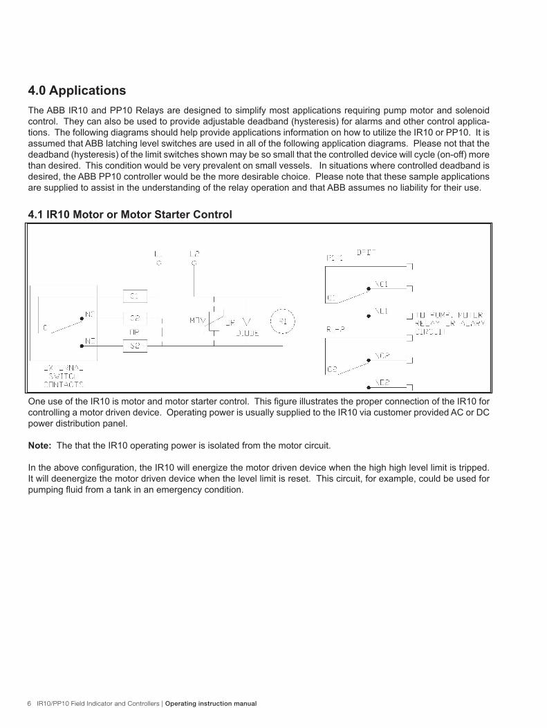
One use of the IR10 is motor and motor starter control. This figure illustrates the proper connection of the IR10 for controlling a motor driven device. Operating power is usually supplied to the IR10 via customer provided AC or DC power distribution panel.
Note: The that the IR10 operating power is isolated from the motor circuit.
In the above configuration, the IR10 will energize the motor driven device when the high high level limit is tripped. It will deenergize the motor driven device when the level limit is reset. This circuit, for example, could be used for pumping fluid from a tank in an emergency condition.
4.1 IR10 Motor or Motor Starter Control
4.0 ApplicationsThe ABB IR10 and PP10 Relays are designed to simplify most applications requiring pump motor and solenoid control. They can also be used to provide adjustable deadband (hysteresis) for alarms and other control applica-tions. The following diagrams should help provide applications information on how to utilize the IR10 or PP10. It is assumed that ABB latching level switches are used in all of the following application diagrams. Please not that the deadband (hysteresis) of the limit switches shown may be so small that the controlled device will cycle (on-off) more than desired. This condition would be very prevalent on small vessels. In situations where controlled deadband is desired, the ABB PP10 controller would be the more desirable choice. Please note that these sample applications are supplied to assist in the understanding of the relay operation and that ABB assumes no liability for their use.
Operating instruction manual | IR10/PP10 Field Indicator and Controllers 7
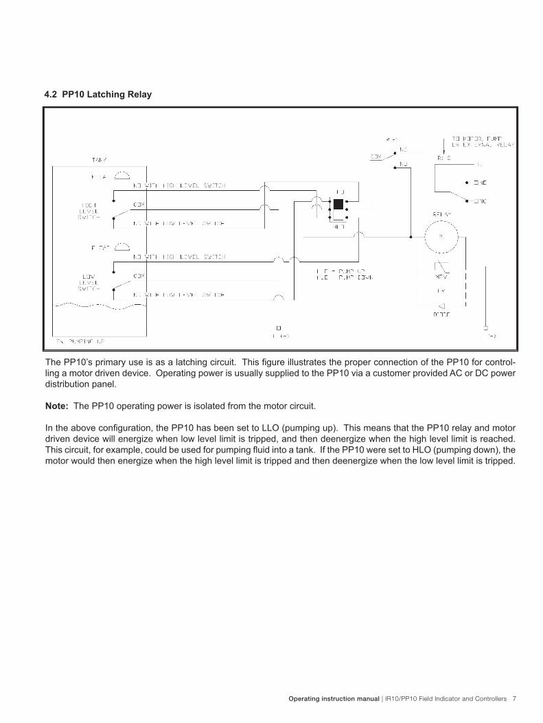
4.2 PP10 Latching Relay
The PP10’s primary use is as a latching circuit. This figure illustrates the proper connection of the PP10 for control-ling a motor driven device. Operating power is usually supplied to the PP10 via a customer provided AC or DC power distribution panel.
Note: The PP10 operating power is isolated from the motor circuit.
In the above configuration, the PP10 has been set to LLO (pumping up). This means that the PP10 relay and motor driven device will energize when low level limit is tripped, and then deenergize when the high level limit is reached. This circuit, for example, could be used for pumping fluid into a tank. If the PP10 were set to HLO (pumping down), the motor would then energize when the high level limit is tripped and then deenergize when the low level limit is tripped.
8 IR10/PP10 Field Indicator and Controllers | Operating instruction manual
5.0 Appendix - Reed Switch ProtectionMany of ABB’s switch products (MS30, MS30/EX, MS50) are based on magnetically operated reed switches. Since reed switches have the inherent characteristic of very closely spaced switch contacts, it is extremely important to protect these contacts from high voltage transients caused by inductive loads. When an inductive load is deener-gized, the collapsing magnetic field induces a high voltage of opposite polarity into itself and thus the switch. Two basic methods exist to clamp this voltage and thus protect the switch contacts.
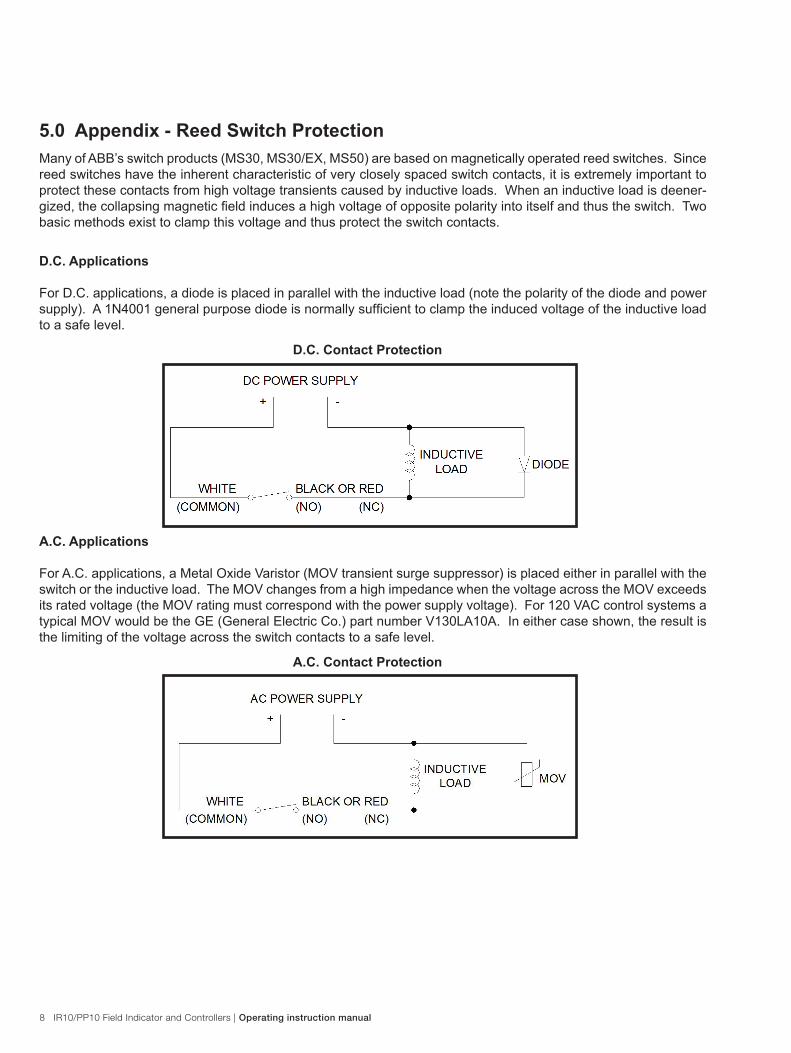
D.C. Applications
For D.C. applications, a diode is placed in parallel with the inductive load (note the polarity of the diode and power supply). A 1N4001 general purpose diode is normally sufficient to clamp the induced voltage of the inductive load to a safe level.
D.C. Contact Protection
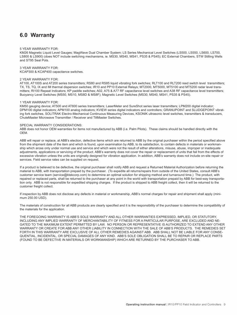
A.C. Applications
For A.C. applications, a Metal Oxide Varistor (MOV transient surge suppressor) is placed either in parallel with the switch or the inductive load. The MOV changes from a high impedance when the voltage across the MOV exceeds its rated voltage (the MOV rating must correspond with the power supply voltage). For 120 VAC control systems a typical MOV would be the GE (General Electric Co.) part number V130LA10A. In either case shown, the result is the limiting of the voltage across the switch contacts to a safe level.
A.C. Contact Protection
Operating instruction manual | IR10/PP10 Field Indicator and Controllers 9
5 YEAR WARRANTY FOR:KM26 Magnetic Liquid Level Gauges; MagWave Dual Chamber System; LS Series Mechanical Level Switches (LS500, LS550, LS600, LS700, LS800 & LS900) (does NOT include switching mechanisms, ie. MS30, MS40, MS41, PS35 & PS45); EC External Chambers, STW Stilling Wells and ST95 Seal Pots.
3 YEAR WARRANTY FOR:KCAP300 & KCAP400 capacitance switches.
2 YEAR WARRANTY FOR:AT100, AT100S and AT200 series transmitters; RS80 and RS85 liquid vibrating fork switches; RLT100 and RLT200 reed switch level transmitters; TX, TS, TQ, IX and IM thermal dispersion switches; IR10 and PP10 External Relays; MT2000, MT5000, MT5100 and MT5200 radar level trans-mitters; RI100 Repeat Indicators; KP paddle switches; A02, A75 & A77 RF capacitance level switches and A38 RF capacitance level transmitters; Buoyancy Level Switches (MS50, MS10, MS8D & MS8F); Magnetic Level Switches (MS30, MS40, MS41, PS35 & PS45).
1 YEAR WARRANTY FOR:KM50 gauging device; AT500 and AT600 series transmitters; LaserMeter and SureShot series laser transmitters; LPM200 digital indicator; DPM100 digital indicators; APM100 analog indicators; KVIEW series digital indicators and controllers; GRANUPOINT and SLUDGEPOINT vibrat-ing fork switches, SOLITRAK Electro-Mechanical Continuous Measuring Devices, KSONIK ultrasonic level switches, transmitters & transducers, ChuteMaster Microwave Transmitter / Receiver and TiltMaster Switches.
SPECIAL WARRANTY CONSIDERATIONS:ABB does not honor OEM warranties for items not manufactured by ABB (i.e. Palm Pilots). These claims should be handled directly with the OEM.
ABB will repair or replace, at ABB’s election, defective items which are returned to ABB by the original purchaser within the period specified above from the shipment date of the item and which is found, upon examination by ABB, to its satisfaction, to contain defects in materials or workman-ship which arose only under normal use and service and which were not the result of either alterations, misuse, abuse, improper or inadequate adjustments, applications or servicing of the product. ABB’s warranty does not cover the repair or replacement of units that fail from the effects of excessive vibration unless the units are originally designed for vibration application. In addition, ABB’s warranty does not include on-site repair or services. Field service rates can be supplied on request.
If a product is believed to be defective, the original purchaser shall notify ABB and request a Returned Material Authorization before returning the material to ABB, with transportation prepaid by the purchaser. (To expedite all returns/repairs from outside of the United States, consult ABB’s customer service team ([email protected]) to determine an optimal solution for shipping method and turnaround time.) The product, with repaired or replaced parts, shall be returned to the purchaser at any point in the world with transportation prepaid by ABB for best-way transporta-tion only. ABB is not responsible for expedited shipping charges. If the product is shipped to ABB freight collect, then it will be returned to the customer freight collect.
If inspection by ABB does not disclose any defects in material or workmanship, ABB’s normal charges for repair and shipment shall apply (mini-mum 250.00 USD).
The materials of construction for all ABB products are clearly specified and it is the responsibility of the purchaser to determine the compatibility of the materials for the application.
THE FOREGOING WARRANTY IS ABB’S SOLE WARRANTY AND ALL OTHER WARRANTIES EXPRESSED, IMPLIED, OR STATUTORY, INCLUDING ANY IMPLIED WARRANTY OF MERCHANTABILITY OF FITNESS FOR A PARTICULAR PURPOSE, ARE EXCLUDED AND NE-GATED TO THE MAXIMUM EXTENT PERMITTED BY LAW. NO PERSON OR REPRESENTATIVE IS AUTHORIZED TO EXTEND ANY OTHER WARRANTY OR CREATE FOR ABB ANY OTHER LIABILITY IN CONNECTION WITH THE SALE OF ABB’S PRODUCTS. THE REMEDIES SET FORTH IN THIS WARRANTY ARE EXCLUSIVE OF ALL OTHER REMEDIES AGAINST ABB. ABB SHALL NOT BE LIABLE FOR ANY CONSE-QUENTIAL, INCIDENTAL, OR SPECIAL DAMAGES OF ANY KIND. ABB’S SOLE OBLIGATION SHALL BE TO REPAIR OR REPLACE PARTS (FOUND TO BE DEFECTIVE IN MATERIALS OR WORKMANSHIP) WHICH ARE RETURNED BY THE PURCHASER TO ABB.
6.0 Warranty

10 IR10/PP10 Field Indicator and Controllers | Operating instruction manual

Operating instruction manual | IR10/PP10 Field Indicator and Controllers 11
OI/
IR10
-EN
Rev
. D
06.2
012
Contact us
NoteWe reserve the right to make technical changes or modify the contents of this document without prior notice. With regard to purchase orders, the agreedparticulars shall prevail. ABB does not accept any responsibility whatsoever for potential errors or possible lack of information in this document.
We reserve all rights in this document and in the subject matter and illustrations contained therein. Any reproduction, disclosure to third parties or utilization of its contents - in whole or in parts – is forbidden without prior written consent of ABB.
Copyright© 2012 ABBAll rights reserved
ABB Inc. 18321 Swamp RoadPrairieville, LA 70769 USAPhone: +1 225 673 6100Service: +1 225 677 5836Fax: +1 225 673 2525Service e-mail: [email protected]
www.abb.com/level