iri1-er stabilized earth fault current relay · 6.2 setting of the pick-up value for the ... by...
TRANSCRIPT

TB IRI1-ER 02.97 E 1
IRI1-ER - Stabilized Earth Fault Current Relay

2 TB IRI1-ER 02.97 E
Contents
1. Summary
2. Applications
3. Characteristics and features
4. Design4.1 Connections4.1.1 Analog inputs4.1.2 Output relays4.2 Front plate4.2.1 LEDs4.2.2 DIP-switches4.2.3 <RESET> push button4.3 Code jumper
5. Working principle
6. Operations and settings6.1 Layout of the operating elements6.2 Setting of the pick-up value for the
differential current ID6.2.1 Indication of fault6.3 Reset6.3.1 Reset by pressing the <RESET> push button6.3.2 Automatic reset6.4 Calculation of the tripping current and
the stabilizing resistance6.4.1 Sample calculation - alternator6.4.2 Example calculation - transformer
7. Housing7.1 Individual housing7.2 Rack mounting7.3 Terminal connections
8. Relay testing and commissioning8.1 Power On8.2 Checking the set values8.3 Secondary injection test8.3.1 Test equipment8.3.2 Example of a test circuit for a
IRI1-3ER-relay8.3.3 Checking the pick-up and tripping values
(IRI1-ER)8.3.4 Checking the operating and resetting
values (IRI1-3ER)8.4 Primary injection test8.5 Maintenance
9. Technical Data9.1 Measuring input9.2 Auxiliary voltage9.3 General data9.4 Output relay9.5 System data9.6 Setting ranges and steps9.7 Dimensional drawing
10. Order form
TB IRI1-ER 02.97 E 3
1. Summary
The application of powerful microprocessors with MR-and IR-relays of the HIGH TECH LINE provides a largevariety of advantages over power protection systemsof the traditional type.
The MR-protection relays are based exclusively on themicroprocessor technology. They represent our most ef-ficient generation of power protection systems. Be-cause of their capabilities to process measured valuesdigitally and to perform arithmetical and logical opera-tions, they are superior to the traditional analog sys-tems.
Besides, the digital protection relays offer importantadditional advantages such as very low power con-sumption, adaptability, possibilities for self-supervision,flexible construction, selection of relay characteristicsetc.
The IR-protection relays may be based on the micro-processor technology or on the analog technology.They represent a more cost saving generation of relaysof the HIGH TECH LINE, used for basic equipment pro-tection.
The IR-protection relays are superior to conventionalprotective devices because of their following charac-teristics:
• Integration of multiple protective functions into onecompact housing
• User-friendly setting procedure by means ofDIP-switches
• Compact construction type by SMD-technology
MR-protection relays are used for more complexe pro-tective functions, such as for example for earth fault di-rectional detection, and also in cases where easy op-eration, quick fault-analysis and optimal communica-tion capabilities are required.
All relays of the HIGH TECH LINE are available for frontplate installation, as well as for 19 rack mounting.Plug-in technology is used. Of course, all relays com-ply with the IEC/DIN regulations required for the spe-cific protection application.
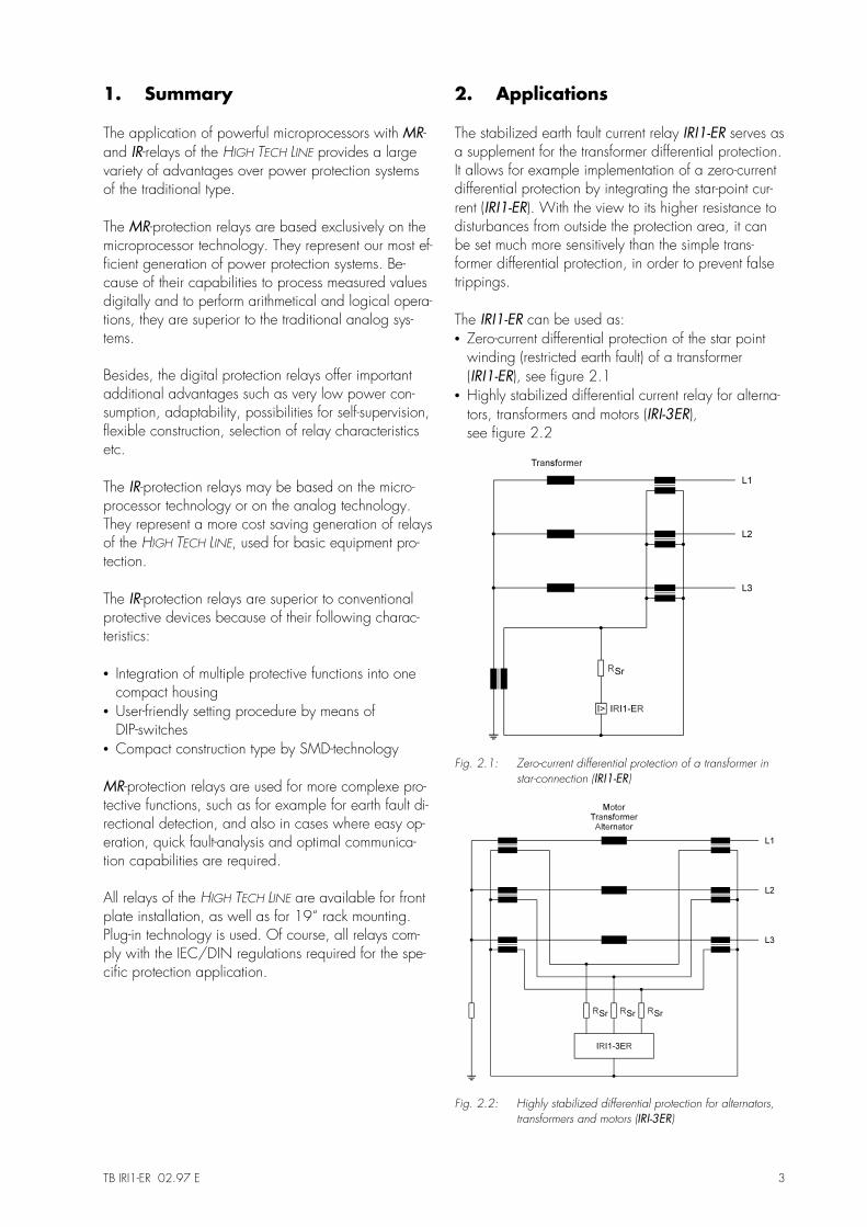
2. Applications
The stabilized earth fault current relay IRI1-ER serves asa supplement for the transformer differential protection.It allows for example implementation of a zero-currentdifferential protection by integrating the star-point cur-rent (IRI1-ER). With the view to its higher resistance todisturbances from outside the protection area, it canbe set much more sensitively than the simple trans-former differential protection, in order to prevent falsetrippings.
The IRI1-ER can be used as:• Zero-current differential protection of the star point
winding (restricted earth fault) of a transformer(IRI1-ER), see figure 2.1
• Highly stabilized differential current relay for alterna-tors, transformers and motors (IRI-3ER),see figure 2.2
Fig. 2.1: Zero-current differential protection of a transformer in star-connection (IRI1-ER)
Fig. 2.2: Highly stabilized differential protection for alternators, transformers and motors (IRI-3ER)
4 TB IRI1-ER 02.97 E
3. Characteristics and features
• static protective device• single-phase current measuring (IRI1-ER) as
zero-current differential protection (restrictedearth fault 64 REF)
• three-phase current measuring (IRI1-3ER)as phase-current differential protection
• high stability by serial stabilizing resistor Rsr perphase
• high sensitivity by low input burden of C.T.• extremely large setting range for current reaction
value with fine grading• wide range of operation of the supply voltage
(AC/DC)• coding for the self-holding function or automatic
reset of the LED`s and trip relays• frequency range 50/60 Hz• rated current 1A or 5A• output relay with 2 change-over contacts
4. Design
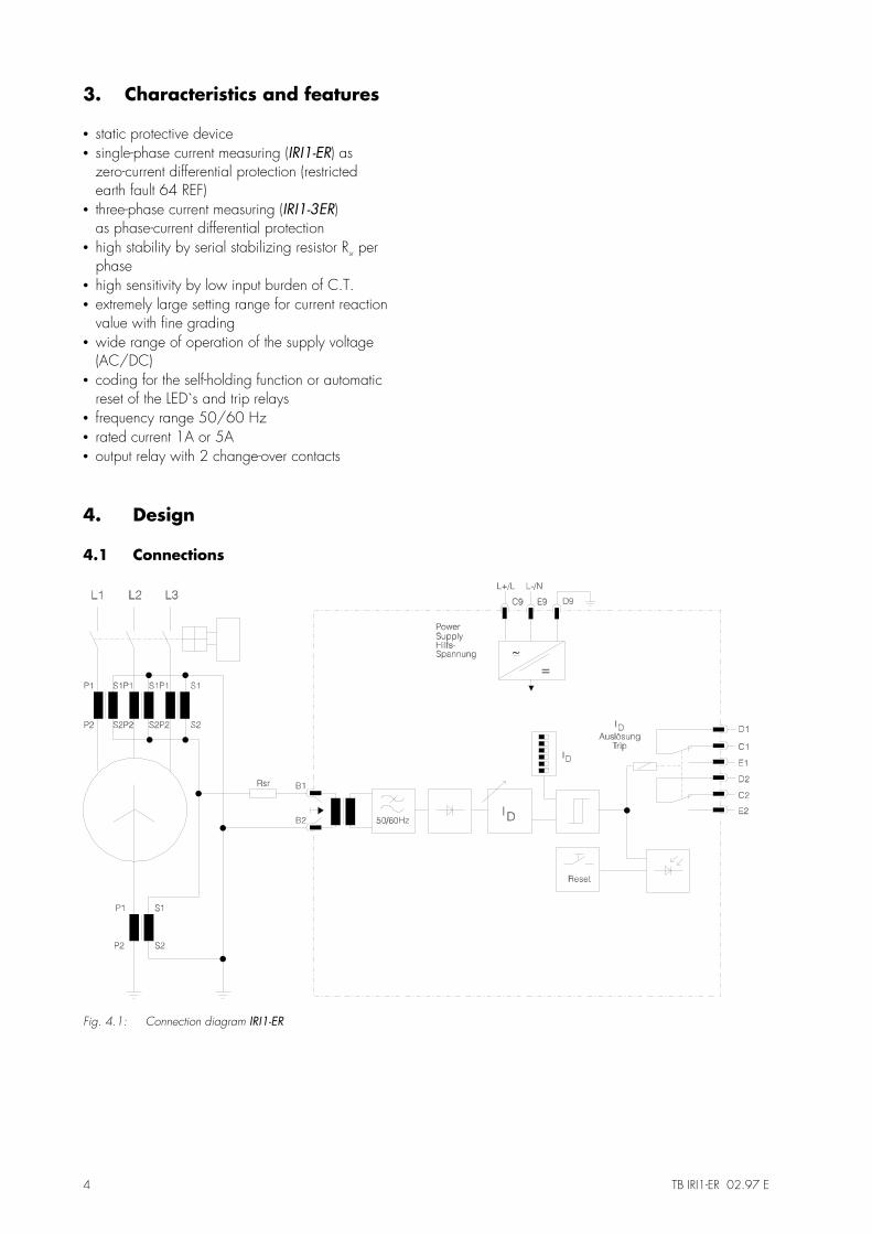
4.1 Connections
Fig. 4.1: Connection diagram IRI1-ER

TB IRI1-ER 02.97 E 5
Fig. 4.2: Connection diagram IRI1-3ER
4.1.1 Analog inputs
At three-phase measuring, the analog input signals ofthe differential currents are fed to the protectivedevice via terminals B1 to B6 (IRI1-3ER), respectivelyat single phase measuring via terminals B1/B2(IRI1-ER).
4.1.2 Output relays
Both relay types are equipped with a trip relay withtwo change-over contacts.
Tripping ID : D1, C1, E1
D2, C2, E2

6 TB IRI1-ER 02.97 E
4.2 Front plate
Fig. 4.3: Front plate
The front plate of the IRI1-ER comprises the followingoperation and indication elements:
• 1 set of DIP-switches for setting the tripping value• 2 LEDs for indication of faults- and readyness for op-
eration• 1 <RESET> push button
4.2.1 LEDs
On the front plate of the IRI1-ER 2 LEDs are installed,signalizing the following 2 service conditions:• LED ON (green): readyness for service• LED ID (red): tripping
4.2.2 DIP-switches
The set of DIP switches on the front plate serves for set-ting the tripping value for the differential current ID.
4.2.3 <RESET>-push button
The <RESET> push button is used for acknowledge-ment and reset of the LED and the tripping relay aftertripping at the specifically preset value (see 4.3).
4.3 Code jumper
Behind the front plate, two coding jumpers are in-stalled at the bottom side for presetting the LED-display,as well as for the tripping function of the output relay.
Fig. 4.4: Code jumper
Codejumper
Function Position ofcode jumper
Operating mode
3 Differential current OFF latching of the red LED IDindication ON automatic reset of the red LED ID
4 Differential current OFF latching of the tripping relaytripping ON automatic reset of the tripping relay
Table 4.1 Code jumper

TB IRI1-ER 02.97 E 7
5. Working principle
The protection relay IRI1-ER is connected to the differ-ential circuit of the c.t.s as a current differential protec-tion relay. When used as zero-current differential pro-tection (restricted earth fault), the relay (IRI1-ER) is to beconnected acc. figure 2.1. When used as highly sta-bilized differential current relay, the relay (IRI1-3ER) isto be connected acc. figure 2.2.
The knee voltage UKn is an important characteristic ofthe transformer.The transformer does not work linearly anymore abovethis voltage. Two transformers of the same class stillshow the same behavior below UKn within the scope oftheir precision class. Above UKn they can, however,show very different saturation behavior.
Connected in a differential current circuit an apparentfault current can thus be measured at large primarycurrent intensity which really results only from the dif-ferent saturation of both transformers.
An additional stabilizing resistor RST counteracts this ef-fect. It attenuates the current flow through the measur-ing device. This way the unsaturated transformer drivespart of its current into the saturated transformer andminimizes the faulty differential current effect on secon-dary side. By small currents the stabilizing resistor ef-fects however also the accuracy of the real fault cur-rent measurement. Because this effect lies in a liniarrange it can be taken into consideration mathmaticallyby adjusting the protection device.(see para. 6.4).
For demonstrating the working principle, figure 5.1shows the single-line diagram of the IRI1-ER.
Fig. 5.1 Single line diagram IRI1-ER
The harmonics existing during a transformer saturationand the DC-component are suppressed by a filter cir-cuit located in the input circuit of the relay; the filtercircuit is adjusted to the mains frequency (50/60Hz).
The IRI1-ER has a single-phase differential current su-pervision with an adjustable pick-up value. The currentmeasured in the differential circuit is constantly com-pared with the set reference value.
Measuring principle IRI1-ER
The analog current signals are galvanically decoupledvia the input transformer and are led over a low passwith subsequent band-pass for suppression of the har-monics, then rectified and compared with the set ref-erence value of a comparator. In case the currentmeasured exceeds the reference value, an instantane-ous tripping takes place (figure 4.1).
The IRI1-3ER has a three-phase differential current su-pervision with adjustable pick-up value. The currentsmeasured in the individual differential circuits are con-stantly compared with the set reference value.
Measuring principle IRI1-3ER
The analog current signals are galvanically decoupledvia three input transformers and led over a low passwith subsequent band-pass for suppressing the harmon-ics. Then rectified and compared with the set referencevalue of a comparator. In case one of the three cur-rents measured exceeds the reference value, an instan-taneous tripping takes place (figure 4.2).

8 TB IRI1-ER 02.97 E
6. Operations and settings
6.1 Layout of the operating elements
The DIP-switch required for setting of parameters is lo-cated on the front plate of the relay.
6.2. Setting of the pick-up value for the differential current ID
The pick-up value of the differential current tripping IDcan be set by means of the DIP-switches set ID in therange of 5% to 82.5% x IN with a grading of 2.5%.
The pick-up value is calculated by adding up the val-ues of all DIP-switches.
Example:A pick-up value of 30% of the rated current is required.
6.2.1 Indication of fault
The fault alarm is shown by the LED ID on the frontplate of the relay, which lights up red at tripping.
Depending on the coding by means of the codejumper (see chapter 6.3.2), the fault alarm extin-guishes automatically or after pressing the <RESET>push button, after the fault is eliminated.
6.3 Reset
6.3.1 Reset by pressing the <RESET>-push-button
By pressing the <RESET> push button, the tripping re-lay is reset and the LED-signal extinguishes. All codingswitches must be plugged out for this (see chapter4.3).
6.3.2 Automatic reset
Code jumper 1If no code jumper is plugged in at coding place 1, thered fault alarm LED ID is coded latching.
The fault signal can only be reset manually by pressingthe <RESET> push button.
If the code jumper is plugged in at coding place 1,the red fault signal LED ID is automatically reset, afterthe fault is eliminated.
Code jumper 2The tripping relay is coded latching, if no code jumperis plugged in on coding place 2.
The tripping relay can only be reset manually by press-ing the <RESET> push button.
If the code jumper is plugged in on coding place 2,the tripping relay is automatically reset after eliminationof the fault.
TB IRI1-ER 02.97 E 9
6.4 Calculation of the tripping current and the stabilizing resistance
Prior to setting the relay, the stabilizing resistance Rsr ,as well as the tripping current Iset must be calculated.For the correct setting, the knee-point voltage in themagnetizing circuit of the c.t. is of special importance.In order to obtain a sufficient differential current fortripping on account of internal faults, the knee-pointvoltage Ukn of the transformer should be twice as highas the maximum expected stabilizing voltage US incase of faults from outside the protection zone. Fromthis results the following calculation:
U U I R RKn S F S L= × = × × +2 2 , sek ( )
Explanation:Ukn knee-point voltage of the magnetizing circuit of
the transformerUs maximum stabilizing voltage in case of external
faultsIf,sek maximum expected fault current (secondary-side) in case of external faultsRS secondary resistance of the transformerRL Resistance of the connection line between c.t.
and relay
The tripping current of the relay is then calculated, asfollows:
IU
2 RD
Kn
Sr≥
⋅
Explanation:RSr stabilizing resistance
The strength of the stabilizing resistance must be se-lected in a way to ensure that the tripping current iswithin the setting range (5% to 82.5% of IN).
When the pick-up value is exceeded, nearly an imme-diate tripping is initiated. With 30 ms the tripping timeis approx. five times as high as the tripping value. Incase of lower currents, the tripping time is slightlyhigher (about 100ms), in order to reach a stabilizationof the protective function against external faults(see also chapter 5).
6.4.1 Sample calculation - alternator
An IRI1-ER protection relay is used for the earth-faultprotection of an alternator. In the starpoint, the follow-ing c.t. is provided:
transformation ratio: 100/1Aclass: 5 P 10output: 2.5 VAsecondary resistanceof the transformer: <0.7Ω
A primary-side fault current of 20% x IN shall be re-corded. The secondary current is used for calculation.
Calculation of the knee-point voltage
If the knee-point voltage is not indicated by the manu-facturer, as is the case in our example, the approxi-mate value can be calculated, as follows:
US k
Ikn
Iü
N≅ ×
⇒ 25 10
125
. ×
= V
Explanation:S output of the c.t.klu overcurrent factor of the c.t.IN secondary-side rated current of the transformer
Calculation of the active resistances
The relevant resistances in the differential circuit addup to a total (circle-) resistance:
RU
IR R R Rkreis
Kn
SetSr L S r=
×
= + × + +2
2
Explanation:Rkreis total resistance in the differential circuitRsr stabilizing resistanceRL resistance of the connection line between
c.t. and relayRs secondary resistance of the transformer (<0.7Ω)Rr relay input resistance (B1 - B2 = 0.02 Ω)ID tripping current
The individual resistance values are:
2 x RL = 150 mΩ, bei 20 m, 2.5 mm² Cu
2 087× + + =R R RL r S . Ω
Therefore, the following is valid:
Rkreis =×
=25
2 02
V
A 62.5
.Ω

10 TB IRI1-ER 02.97 E
Calculation of the stabilizing resistance
The stabilizing resistance is calculated from above ra-tios, as follows:
R R R R R
R
Sr kreis L r S
kreis
= − × + += −
( )
.
2
087
= 61.6
ΩΩ
In operational mode ≤ ID, the output requirement PN isas follows:
PN ≤ I² x Rsr = 0.2² A² x 61.6 Ω ≤ 2.47 W
In this case, PN represents the minimum output required(pure current-heat losses). A considerably increasedoutput PF is required in the event of a fault.
Example: The false current is: IF,prim = 13.1 kA
If one neglects the transformer saturation, the followingpeak voltage UP occurs:
( )UI
nR R Rr Rp
F primSr L S= × + × + +,
2
( )Up = × × =13100
100625 81875
A 1 V. .Ω
If one considers the transformer saturation, a short-termpeak voltage USS occurs, as shown in the followingcalculation:
( )( )U U U USS Kn p Kn= × × × − ≤+
2 2 30 5.
kV
( )( )USS = × × × − =+
2 2 25 81875 25 1280 5
V V V kV. ..
PU
R
VF
SS
Sr= = =
2 2
616266
1280
kW
2
..
Ω
The calculation of PN and PF must be effected in anycase, in order to get the exact power range of thestabilizing resistor.
Take over of power by the resistor in the event of afault PF creates a short-term peak value. The actualvalue is about half of it.For above example, a stabilizing resistance of 62Ωwith 13 kW/1.1 is required for the total earth-faultperiod (f.ex.1 s tripping delay on account of gradua-tion times of external protection equipment +100 ms(individual time of the switch = 1.1s).
6.4.2 Example calculation - transformer
An IRI1-ER protection relay is used for the earth-faultprotection of a 1.6 MVA-transformer (11000/415 V,6%), see figure 2.1. The following c.t.s are used in therigidly earthed starpoint:
transformation ratio: 2 500/1Aclass: Xresistance Rs: 8 Ωknee-point voltage: 250 V
The relay is situated about 20m away from the c.t.sand is connected with a 2.5mm2 cable.
Calculation of the stabilizing voltage
The primary-side fault-current IF,prim is:
IF prim, .=× ×
=1600000 VA
V 6 % kA
3 415371
Line resistance RL (2.5 mm² ≈ 7.46 Ω/km)
RL = × =201000
015 m7.46
m
Ω Ω.
Additional resistance Rr (ca. 0.02 Ω)
From this results the stabilizing voltage for:
( )UI
nR Rs RS
F primL r= × × + +,
2
( )US = × × × + + =37100
25002 015 8 001 1235
A 1 V. . .Ω Ω Ω
Since the knee-point voltage shall be Ukn = 2x US (2 x123,5V = 247 V), the above transformer withUkn = 250 V can be used.
Calculation of the set current and the stabilizingresistance (sample value)
The rating for the set current of 20% is calculated:
ID = 20 % x IN = 0.2 x 1 A = 0.2 A
From this results the stabilizing resistance for:
RUI
RkreisS
DSr=
≈ => 1235
6175.
. V
0.2 A
= Ω
TB IRI1-ER 02.97 E 11
In the event of a fault, the stabilizing resistance mustwithstand a secondary-side false current of:
IF sek, .= ×× × ×
=1600000 VA 1
V 6 % 2500 A
3 4151484
The calculation of the short-term peak voltages pro-vides the following result:
( )Up = × × + × + +
=
37.1 kA
25008 2 015 002 615
925
1
kV
Ω Ω Ω Ω. .
.
Thus, the ratio
( )( )U U U USS Kn p Kn= × × × − ≤+
2 2 30 5.
kV
( )( )USS = × × × − =+
2 2 250 9250 250 4240 5
V V V kV.
.
is not reached and the calculation must be repeatedwith a higher set current.
Calculation of the set current and thestabilizing resistance (actual value)
The rating for the set current of 40% is calculatedagain:
ID = 40 % x IN = 0.4 x 1 A = 0.4 A
From this results the stabilizing resistance for:
RUI
RkreisS
DS=
≈ r => 1235
30875.
. V
0.4 A
= Ω
Thus, the requirement of the short-term peak voltage ismet.
( )Up = × × + × + +
=
37.1 kA
25008 2 015 002 30875
47
1
kV
. . .
.
Ω Ω Ω
( )( )USS = × × × − =+
2 2 250 4700 250 2980 5
V V V kV.
.
Since the requirement is met, the set values and the re-sulting resistance values can be accepted.
The calculation of the output requirement for the stabi-lizing resistance can be carried out analog to the cal-culation of sample 6.4.1.

12 TB IRI1-ER 02.97 E
7. Housing
The IRI1-ER can be supplied in an individual housingfor flush-mounting or as a plug-in module for installationin a 19" mounting rack according to DIN 41494.Both versions have plug-in connections.Relays of variant D are complete devices for flushmounting, whereas relays of variant A are used for19 rack mounting. Housing variant A to be installedin switchboards of protection class IP51. For switch-boards of lower protection classes housing variant Dcan be used.
7.1 Individual housing
The individual housing of the IRI1-ER is constructed forflush-mounting. The dimensions of the mounting framecorrespond to the requirements of DIN 43700 (72 x144 mm). The cut-out for mounting is 68 x 138 mm.
The front of the IRI1-ER is covered with a transparent,sealable flap (IP54).
For case dimensions and cut-out refer to "technicaldata". The individual housing is fixed with the suppliedclasps from the rear of the switchboard panel.
7.2 Rack mounting
The IRI1-ER is in general suitable for installation in amodular carrier according to DIN 41494. The installa-tion dimensions are: 12 TE; 3 HE.
According to requirements, the IRI1-ER-devices can bedelivered mounted in 19" racks.
If 19" racks are used the panel requires protectionclass IP51. For switchboards with lower degree of pro-tection must be used individual housing.
7.3 Terminal connections
The plug-in module has very compact base with plugconnectors and screwed-type connectors.• max. 15 poles screw-type terminals for voltage and
current circuits (terminal connectors series A and Bwith a short time current capability of 500 A / 1 s).
• 27 poles tab terminals for relay outputs, supply volt-age etc.(terminal connectors series C, D and E,max. 6 A current carrying capacity). Connectionwith tabs 6.3 x 0.8 mm for cable up to max. 1.5mm2 or with tabs 2.8 x 0.8 mm for cable up tomax. 1 mm2.
By using 2.8 x 0.8 mm tabs a bridge connection be-tween different poles is possible.
The current terminals are equipped with self-closingshort-circuit contacts. Thus, the IRI1-ER-module can beunplugged even with current flowing, without endan-gering the current transformers connected.
The following figure shows the terminal block ofIRI1-ER:
A B
C D E
1
2
3
4
5
6
7
8
9
F
Fig. 7.1: Terminal block of IRI1-ER

TB IRI1-ER 02.97 E 13
8. Relay testing andcommissioning
The following instructions should help to test the protec-tion relay performance before or during commissioningof the protection system. To avoid a relay damageand to ensure a correct relay operation, be sure that:
• the auxiliary power supply rating corresponds to theauxiliary voltage on site
• the rated current and rated voltage of the relay cor-respond to the plant data on site
• the current transformer circuits are connected to therelay correctly
• all signal circuits and output relay circuits are con-nected correctly
8.1 Power On
NOTE!Prior to switch on the auxiliary power supply, be surethat the auxiliary supply voltage corresponds to therated data on the type plate.
Switch on the auxiliary power supply to the relay (ter-minal C9/E9) and check that the LED ON on thefront plate lights up green.
8.2 Checking the set values
Check the DIP-switch positions, in order to verify theparameterized set value. If necessary, the set valuecan be corrected by means of the DIP-switch.
8.3 Secondary injection test
8.3.1 Test equipment
• ammeter of class 1 or better• auxiliary power supply with a voltage correspond-
ing to the rated data on the type plate• single-phase AC-power supply (adjustable
from 0 - 2.0 x IN)• test leads and tools• potentiometer• switching device• timer
8.3.2 Example of a test circuit for aIRI1-3ER-relay
For testing the IRI1-3ER-relay, only power signals arerequired. Fig. 8.3.1 shows an example of a test circuitwith adjustable power supply. The phases are testedindividually one after the other.
Fig. 8.3.1 Test circuit IRI1-3ER

14 TB IRI1-ER 02.97 E
8.3.3 Checking the pick-up and tripping values (IRI1-ER)
With the IRI1-ER, the analog input signal of the single-phase testing AC must be supplied to the relay via theterminals B1/B2 for checking the pick-up value ID.
For testing the differential current pick-up value, first thetesting AC must be set below the set pick-up value Id.Thenthe testing AC is increased gradually, until the relay istrips. This is indicated by the LED ID lighting up red,with the relay tripping at the same time. Check that thevalue shown at the ammeter does not deviate by morethan +/- 3% from the set pick-up value ID .
The resetting value of the differential current pick-upvalue is determined, by slowly decreasing the testingAC, until the output relay ID is trips. The LED ID extin-guishes (supposed the respective coding was ef-fected).
Check that the resetting value is greater than 0.97times the pick up value, i.e. the resetting ratio of thedifferential current supervision is below 1.
8.3.4 Checking the operating andresetting values (IRI1-3ER)
With the IRI1-3ER, all analog input signals of the sin-gle-phase testing AC must be supplied to the relay viathe terminals B1/B2; B3/B4; B5/B6 one after an-other for checking the pick-up value ID.
For testing the differential current pick-up value, first thetesting AC must be set below the set pick-up valueId.Then the testing AC is increased gradually, until therelay is trips. This is indicated by the LED ID lighting upred, with the relay tripping at the same time. Checkthat the value shown at the ammeter does not deviateby more than +/- 3% from the set pick-up value ID .
The resetting value of the differential current pick-upvalue is determined, by slowly decreasing the testingAC, until the output relay ID is tripping. The LED ID ex-tinguishes (supposed the respective coding was ef-fected).
Check that the resetting value is not lower than 0.97times the pick up value, i.e. the resetting ratio of thedifferential current supervision is below 1.
Note: An external timer must be used for checking thetripping time (individual time of the relay).
8.4 Primary injection test
Principally, a primary injection test (real-time test) of ac.t. can be carried out in the same way as a secon-dary injection test. Since the cost and potential haz-ards may be very high for such tests, they should onlybe carried out in exceptional cases, if absolutely nec-essary.
8.5 Maintenance
Maintenance testing is generally done on site at regu-lar intervals.These intervals may vary among users de-pending on many factors: e.g. type of protective re-lays employed; type of application; operating safety ofthe equipment to be protected; the users past experi-ence with the relay etc.
For static relays such as the IRI1-ER/-3ER, mainte-nance testing once per year is sufficient, as experiencehas shown.

TB IRI1-ER 02.97 E 15
9. Technical Data
9.1 Measuring input
Rated data:Nominal current IN 1A/5ANominal frequency fN 50/60 Hz
Power consumption <1 VA/at IN = 1Ain current circuit: <5 VA/at IN = 5 A
Thermal withstand dynamic current withstand (half-wave) 250 x INcapability of current for 1 s 100 x INcircuit for 10 s 30 x IN
continuously 4 x IN
9.2 Auxiliary voltage
Rated auxiliary voltage UH: 24 V - working range 16 - 60 V AC / 16 - 80 V DC110 V - working range 50 - 270 V AC / 70 - 360 V DCPower consumption: 24 V - working range standby approx. 3 W operating approx. 6 W110 V - working range standby approx. 3 W operating approx. 6 W
9.3 General data
Permissible interruption ofthe supply voltage withoutinfluence on the function 50 msDropout to pickup ratio: >97%Returning time: 30 msMinimum operating time: 30 ms
9.4 Output relay
The output relay has the following characteristics:Maximum breaking capacity: 250 V AC / 1500 VA / continuous current 6 A
Breaking capacity for DC:
Max. rated making current 64 A (acc. VDE 0435/0972 and IEC 65 / VDE 0860 / 8.86)Making current: minimum 20 A (16ms)Mechanical life span: 30 x 106 switching cyclesElectrical life span: 2 x 10⁵ switching cycles at 220 V AC / 6 AContact material: silver-cadmium-oxyde
ohmsch L/R = 4 ms L/R = 7 ms300 V DC 0.3 A / 90 W 0.2 A / 63 W 0.18 A / 54 W250 V DC 0.4 A / 100 W 0.3 A / 70 W 0.15 A / 40 W110 V DC 0.5 A / 55 W 0.4 A / 40 W 0.20 A / 22 W60 V DC 0.7 A / 42 W 0.5 A / 30 W 0.30 A / 17 W24 V DC 6.0 A / 144 W 4.2 A / 100 W 2.50 A / 60 W

16 TB IRI1-ER 02.97 E
9.5 System data
Design standard:Generic standard: EN 50082-2, EN 50081-1Product standard: EN 60255-6, IEC 255-4, BS 142
Specified ambient serviceStorage temperature range: - 40°C to + 85°COperating temperature range: - 20°C to + 70°C
Environmental protection class Fas per DIN 40040 and perDIN IEC 68 2-3: relative humidity 95 % at 40°C for 56 days
Insulation test voltage, inputsand outputs between themselvesand to the relay frame as perEN 60255-6 and IEC 255-5: 2.5 kV (eff.), 50 Hz; 1 min
Impulse test voltage, inputsand outputs between themselvesand to the relay frame as perEN 60255-6 and IEC 255-5: 5 kV; 1.2 / 50 µs; 0.5 J
High frequency interferencetest voltage, inputs and outputsbetween themselves and to therelay frame as per EN 60255-6and IEC 255-22-1: 2.5 kV / 1MHz
Electrostatic discharge (ESD) test asper EN 61000-4-2 and IEC 255-22-1: 8 kV air discharge, 6 kV contact discharge
Electrical fast transient (Burst) test asper EN 61000-4-8 and IEC 801-4: 4 kV / 2.5 kHz, 15 ms
Power frequency magnetic fieldtest as per ENV 50141: electric field strength 10 V/m
Surge immunity EN 61000-4-5: 4 kV
Radio interference suppressiontest as per EN 55011: limit value class B
Radio interference radiation testas per EN 55011: limit value class B
Mechanical tests:
Shock: class 1 acc. to DIN IEC 255-21-2Vibration: class 1 acc. to DIN IEC 255-21-1Degree of protection - front of relay: IP 54 by enclosure of the relay case and front panel (relay version D)Weight: approx. 1.5 kg
Degree of pollution: 2 by using housing type A3 by using housing type D

TB IRI1-ER 02.97 E 17
Overvoltage class: III
Influence variable values:
Frequency influence: 40 Hz < f < 70 Hz: <3 % of set valueTemperature influence: -20°C bis +70°CAuxiliary voltage influence: no influence within the admissible range
9.6 Setting ranges and steps
Relay type Parameter Setting range Steps TolerancesIRI1-ER ID 5 % ... 82.5 % x IN 2.5 % ± 3 % of set valueIRI1-3ER ID 5 % ... 82.5 % x IN 2.5 % ± 3 % of set value
9.7 Dimensional drawing
Please note:
A distance of 50 mm is necessary when the units are mounted one below the other in order to allow easyopening of the front cover of the housing. The front cover opens downwards.

18 TB IRI1-ER 02.97 E
10. Order form
Stabilized earth-fault current relay IRI1-
Measuring of earth current high stabilized ER3-phase measuring 3ER
Rated current in the earth-faultphase
1 A 1
5 A 5Auxiliary voltage 24 V (16 bis 60 V AC / 16 bis 80 V DC) L
110 V (50 bis 270 V AC / 70 bis 360 V DC) HHousing (12TE) 19 rack A
Flash mounting D
Technical data subject to change without notice !

TB IRI1-ER 02.97 E 19
Setting list IRI1-ER
Note !All settings must be checked at site and should the occasion arise, adjusted to the object / item to be protected.
Project: SEG job.-no.:
Function group: = Location: + Relay code: -
Relay functions:
Setting of parameters
Parameter Unit Defaultsettings
Actualsettings
ID Differential current % In 5
Setting of code jumpers
Code jumper J1 J2 J3 J4Defaultsetting
Actualsetting
Defaultsetting
Actualsetting
Defaultsetting
Actualsetting
Defaultsetting
Actualsetting
Plugged X X
Not plugged not used not used

20 TB IRI1-ER 02.97 E