irpa 2010 proceedings: s05-p05 waste management and
TRANSCRIPT

Session 5: Waste management and decommissioning Oral presentationsS05
S05-01 Finland’s approach to licensing and regulatory control of geological repository for spent nuclear fuel . . . . . . . . . . . . . . . . . . 956Varjoranta, Tero; Paltemaa, Risto
S05-02 Sweden’s National Radioactive Waste Management Plan (ABSTRACT) . . . . 961Brewitz, Erica
S05-03 Optimization of management of radioactive waste generated in research and education centres . . . . . . . . . . . . . . . . . . . . . . . . . 962Macias, Mª Teresa; Pulido, Juan; Pérez, Jorge; Sastre, Guillermo; Sánchez, Angeles; Usera, Fernando
S05-04 Radiation Protection organization in radioactive waste management at the Joint Research Centre of Ispra . . . . . . . . . . . . . . . . . . . . . 972Accorsi, Roberto; Giuffrida, Daniele; Osimani, Celso
S05-05 The safe decommissioning of two plutonium contaminated facilities at Dounreay . . . . . . . . . . . . . . . . . . . . . . . . . . . . . . . . . 982Thompson, Peter; White, Simon
S05-06 Radiation protection issues related to the decommissioning of the DR3 research reactor . . . . . . . . . . . . . . . . . . . . . 992Søgaard-Hansen, Jens; Hedemann Jensen, Per
S05-07 Alara aspects in dismantling of the irradiated fuel reprocessing pilot Plant MTR Type (M1 Plant) . . . . . . . . . . . . . . . . . . . . . 1000Ruiz Martínez, José Tomás; Gutierrez Moratal, José Miguel; Zurita Montero, Antonio
S05-08 Protocol for the clearance and release for metal materials from SLAC National Accelerator Laboratory – Application to BaBar Detector Dismantling (ABSTRACT) . . . . . . . . . . . . . 1009Liu, James; Fasso, Alberto; Kerimbaev, Emil; Rokni, Sayed; Sabourov, Amanda; Vollaire, Joachim; Yamanishi, Hirokuni
S05-09 Development of radiochemical analytical method for the determination of radionuclides difficult to measure for decommissioning of nuclear facilities (ABSTRACT) . . . . . . . . . . . . . . . . 1010Hou, Xiaolin
Third European IRPA Congress 2010, Helsinki, Finland
Contents

Topic 5: Waste management and decommissioning Poster presentationsP05
P05-01 Meaning of site-specific data in dose assessment: case of concentration ratios in boreal forest . . . . . . . . . . . . . . . . . . . . . . . . . 1011Ikonen, Ari T. K.; Aro, Lasse; Helin, Jani
P05-02 A graded approach to dose assessment in the Posiva safety case . . . . . . . 1019Hjerpe, Thomas; Avila, Rodolfo; Ikonen, Ari T. K.; Broed, Robert
P05-03 On a simple method for proving clearance conditions for radioactive waste (ABSTRACT) . . . . . . . . . . . . . . . . . . . . . . . . 1029Toro, Laszlo; Stafie, Adrian
P05-04 A comparative overview of waste management concepts for large components . . . . . . . . . . . . . . . . . . . . . . . . 1030Meissner, Frank; Bauerfeind, Matthias
P05-05 Recovery from old intermediate level liquor spillage in redundant magnox waste Silo (ABSTRACT) . . . . . . . . . . . . . . . . . 1036Brown, Andrew; Doyle, Ken
P05-06 Efficient and environmentally sound management of radioactive waste streams from maintenance, upgrade and decommissioning . . . . . . 1037Stenmark, Anders
Third European IRPA Congress 2010, Helsinki, Finland
Contents

956
Session 5: Waste management and decommissioning Oral presentations
Finland’s approach to licensing and regulatory control of geological repository for spent nuclear fuel
Varjoranta, Tero; Paltemaa, Risto Radiation and Nuclear Safety Authority, STUK, P.O.Box 14, FI-0881 Helsinki, FINLAND
Abstract Finland’s program for the disposal of spent nuclear fuel is among the most advanced in the world. The first licensing step, the Decision-in-Principle, which sealed public acceptance on local and national level, was taken in 2000-2001. Site confirmation studies, the construction of an underground rock characterization facility and the development of the safety case for the facility are ongoing and the program is approaching the next step, the submittal of construction license application, expected in 2012. All this was preceded by more than 30 years of work with a long-term goal. In this review, the approaches to licensing and regulatory control of the facility are presented.
Introduction There are four nuclear reactor units in operation in Finland, two VVER-440/213-type pressurized water reactors (488MW each) in Loviisa and two ASEA-Atom boiling water reactors (860MWe each) in Olkiluoto. The reactors were commissioned between 1977 and 1980. One reactor unit, a 1600MW EPR, is under construction at Olkiluoto. There are applications pending for new reactors by three companies, on four candidate sites. Currently, about one third of the electricity consumption in Finland is produced by nuclear reactors.
From an early stage in the Finnish reactor program, it was considered that the whole nuclear fuel cycle needs to be taken into account when addressing the safety of nuclear energy production. Over 30 years of systematic research and development has been carried out to select a site, to develop engineered barriers and the safety case and, in parallel, a stepwise regulatory approach for the disposal of spent nuclear fuel produced in Finland.
These activities have been done following Government’s long term strategies since 1983. As the first regulatory step, public acceptance at local, Governmental and Parliament levels was gained in the Decision-in-Principle (DiP) in 2000 to locate the repository at Olkiluoto.
The operators of nuclear facilities/producers of nuclear waste, now Fortum Oyj and Teollisuuden Voima Oyj, have full responsibility for nuclear safety, including the
Third European IRPA Congress 2010, Helsinki, Finland
S05 S05-01
S05-01

957
Session 5: Waste management and decommissioning – Oral presentationsVarjoranta, Tero and Paltemaa, RistoFinland’s approach to licensing and regulatory control of geological repository for spent nuclear fuel
safety of disposal of spent nuclear fuel. For the implementation of the disposal, the NPP operators have formed a jointly owned company, Posiva Oy. The Ministry of Employment and the Economy is responsible for the supreme command and control of nuclear matters, while the Radiation and Nuclear Safety Authority (STUK) is responsible for the supervision of safe use of nuclear energy. STUK is an independent regulatory body with broad authorities to ensure that nuclear power is produced in a safe manner, and to give necessary orders for this purpose.
An application for a Construction License of the disposal facility is expected to be submitted at the end of 2012 and operation of the facility to begin in 2020.
Stepwise licensing In Finland, licensing a nuclear facility proceeds in three steps:
Decision-in-principle Construction of a nuclear facility of considerable general significance requires a Government Decision-in-Principle on that the construction project is “in line with the overall good of society”. Nuclear facilities deemed to be of considerable general significance include nuclear waste disposal facilities.
The Decision-in-Principle is the major political decision on the societal acceptability of the project. An Environmental Impact Assessment process with public consultation and stakeholder involvement must be performed. As a prerequisite for the decision, the Government must obtain the consent of the host municipality and a preliminary safety evaluation by STUK indicating that “no facts indicating a lack of sufficient prerequisites for constructing a nuclear facility have arisen”.
The Decision-in Principle is made by the Government and endorsed or reversed by the Parliament.
Construction license The license to construct a nuclear facility is granted by the Government. It requires an application which must include the justification of safety for the facility, the Safety Case of the designed facility. Based on the application, STUK makes a safety evaluation, which must be positive for the construction license to be granted.
Operating license The license to operate a nuclear facility is also granted by the Government. The Safety Case of the constructed facility is reviewed by STUK and a positive safety evaluation is required for the Government to grant the licence.
Regulatory control From a regulatory viewpoint, the Olkiluoto spent fuel disposal project can be divided into the following main phases: 1. Research phase from the late 1970’s to the Decision-in-Principle licensing phase
(DiP), 2. Research, development and design phase including construction of an
underground rock characterization facility (from DiP to Construction Licence), 3. Construction phase (from Construction Licence to Operating Licence),
Third European IRPA Congress 2010, Helsinki, Finland
S05 S05-01
958
Session 5: Waste management and decommissioning – Oral presentationsVarjoranta, Tero and Paltemaa, RistoFinland’s approach to licensing and regulatory control of geological repository for spent nuclear fuel
4. Operating phase 5. Decommissioning and closure phase.
Before the DiP, the progress in siting and research and developed were followed by annual reporting with STUK’s statements to the ministry.
In the year 2000, the Government made the Decision-in-Principle. The decision also authorized the construction of an underground rock characterization facility, now called ONKALO, in Olkiluoto. The facility may be later used as the access tunnel to the disposal facility and is therefore constructed under full regulatory control.
In addition, research, development and design work by Posiva continued with the aim to arrive at a facility design and a Safety Case for the next licensing stage by 2012. STUK has reviewed Posiva’s plans and evolving drafts of Safety Case documentation, commenting on their adequacy compared to regulator’s expectations.
Construction of ONKALO For long term safety, the main safety functions of the Olkiluoto disposal facility are ensuring the integrity of the engineered containment of the disposed waste and maintaining sub-criticality. The secondary safety functions are the limitation and retardation of the release of radioactive nuclides and isolation of the engineered barrier system from external impacts.
Therefore, it is important that such chemical and mechanical conditions are maintained in the bedrock that the safety functions are not jeopardized over a long period of time in a variety of normal and abnormal circumstances.
Construction of ONKALO to the planned disposal depth (-427m) disturbs the geo-environment and conditions in a variety of ways. The purpose of STUK’s regulatory control of ONKALO construction is primarily to ensure that the design, location, orientation and construction are carried out in such a manner that the geo-environment retains its favourable characteristics and conditions needed for the safety functions.
In particular, this implies the minimization of host rock responses to excavation, the excavation disturbed zone, groundwater leakages to the tunnels and shafts, and introduction of foreign, potentially harmful, substances to ONKALO during
excavation and operation (cement and other grouting materials, reinforcement materials, explosives etc.).
STUK’s regulatory activities (approvals, review and assessment, inspection) of ONKALO are implemented in a graded approach. All structures, systems, components are classified based on their assessed significance to safety.
Posiva’s management system is also subject to STUK’s regulatory control. STUK primarily inspects safety and quality management of Posiva’s organization and reviews Posiva’s self assessment of safety culture.
As a basis for review and assessment, STUK requested from Posiva a plan of the documents to be submitted for information or approval. The plan was an adaptation of that defined in the regulatory guide for nuclear facilities. The documents that must be submitted include description of the constructing organization, staff competences, regulations, codes and standards to be used in the construction, quality system documentation, design data, drawings, construction documentation, etc.
Third European IRPA Congress 2010, Helsinki, Finland
S05 S05-01

959
Session 5: Waste management and decommissioning – Oral presentationsVarjoranta, Tero and Paltemaa, RistoFinland’s approach to licensing and regulatory control of geological repository for spent nuclear fuel
In addition, Posiva was required to submit to STUK a plan describing how the company intends to communicate to STUK the progress of the construction work. The purpose of this document is to facilitate well planned and timely regulatory activities.
In STUK’s review and assessment of ONKALO construction, requirements in current regulatory guides (for nuclear facilities) are used, as applicable, but in many cases they can only be used as a model and new requirements and criteria suitable for this part of the underground disposal facility have to be created.
ONKALO inspection activities cover all areas of STUK’s responsibilities. Inspections are carried out in order to ensure that Posiva is in compliance with regulations, conditions and approvals of STUK. Inspection activities can be divided into:
Construction Inspection Program, Inspections concerning the readiness to begin excavation and work phases,
and Inspection on construction works on site.
From the Construction Inspection Program, five to ten inspections are performed annually. The inspection program has a three-level hierarchy:
Level A, Management system: safety management, organization, safety culture, quality assurance, competence of staff, communication with STUK,
Level B, Main Operations: construction project management and resources, safety issues, quality assurance for construction work, monitoring program, related R&D,
Level C, Functions and Activities: Posiva’s inspections and QC, excavation and excavation disturbed zone, drillings, mapping of features, construction impacts (to geochemistry, rock mechanics, hydrogeology, groundwater leakages to tunnels and shafts, introduction of foreign materials, grouting, enforcement works and materials), physical protection and emergency preparedness.
ONKALO construction is divided into different phases. The purpose of the inspections concerning the readiness to begin excavation and work phases is to ensure that all the arrangements and conditions at the construction site are in order for the next construction phase to start (previous phase is properly completed).
Examples of this type of inspections are inspecting the preparedness to begin shotcreting a specified tunnel section, and inspecting the preparedness to start a new excavation piece-work.
Inspections on construction works on site, carried out at least once in two weeks, focus on work processes, methods and practices, and their quality and compliance with approvals.
Posiva’s research, development and design activities During this period between the DiP and the submittal of Construction License application, STUK’s regulatory control of Posiva’s RD&D activities focuses primarily on the gradually evolving facility design and the drafts of Safety Case documentation.
Posiva has a program of producing the documentation for the long-term Safety Case, 10 main reports, in a several advancing versions, before final versions submitted with the Construction License application. STUK has reviewed these reports and
Third European IRPA Congress 2010, Helsinki, Finland
S05 S05-01

960
Session 5: Waste management and decommissioning – Oral presentationsVarjoranta, Tero and Paltemaa, RistoFinland’s approach to licensing and regulatory control of geological repository for spent nuclear fuel
commented on them, compared with regulatory expectations, and identified safety questions that need to be resolved before the next licensing phase.
As a required maturity test, Posiva submitted recently the current drafts of their Construction License application material to STUK and Ministry of Employment and the Economy. This material includes the draft Preliminary Safety Analysis Report and drafts of most reports included in the long-term Safety Case. The regulators review if the pre-license application demonstrates sufficient readiness from scientific, technological and safety viewpoint to justify the actual construction licensing process to start in 2012.
Regulations, guides and regulatory decisions are developed and taken in parallel with the proceeding RD&D work.
In support of its regulatory staff, STUK has organized the three international experts groups for
Olkiluoto site safety investigations, Engineered Barrier System and Technology, and Safety Assessment.
Nuclear Safeguards As ONKALO is foreseen to become a part of the disposal facility for spent nuclear fuel, STUK decided in 2003 to start to require the application of nuclear safeguards measures to ONKALO. Posiva was obliged to implement safeguards procedures from the beginning of the excavation to the closure of the disposal facility site. As required by STUK, Posiva has prepared and documented all necessary safeguards procedures and measures in their “Safeguards Handbook” and submitted it regularly to STUK for review and approval.
Safeguards activities for spent fuel disposal in Finland have four main objectives: to ensure that all safeguards relevant information about the final disposal
facility will be available in due time; to be able to confirm that there are no undeclared activities relevant to
safeguards at or near the final disposal site; to enable the IAEA to perform integrated safeguards in Finland; to enable the IAEA and the European Commission to plan for their future
safeguards activities. STUK’s current safeguards activities consist of auditing Posiva’s safeguards
implementation, reviewing Posiva’s safeguards relevant reports and confirming by on-site inspections that ONKALO is in compliance with Posiva’s as-built documentation.
STUK’s audit of Posiva’s safeguards implementation includes review of the documented results and the observations made throughout the year in connection with report reviews and on-site inspections. Result of STUK audits are fed back to STUK’s regulatory process and to Posiva.
Conclusions Finland’s program for the disposal of spent nuclear fuel is approaching the construction license phase. In parallel with the progress of the disposal project, an approach to regulatory control has been developed, as described in this paper.
Third European IRPA Congress 2010, Helsinki, Finland
S05 S05-01

961
Session 5: Waste management and decommissioning Oral presentations
Preliminary results on Cernavoda NPP operation impact on terrestrial and aquatic biota
Bobric, Elena1; Varlam, Carmen2; Popescu, Ion1; Simionov, Vasile1
1 Cernavoda NPP, Health Physics Department, ROMANIA 2 National Institute R&D for Cryogenic and Isotopic Technologies, Rm. Valcea, ROMANIA
Abstract Recently, the awareness of the vulnerability of the environment has increased and the need to protect it against industrial pollutants has been recognized. The concept of sustainable development, requires new and developing international policies for environmental protection. (Protection of the environment from the effects of ionizing radiation. IAEA-TECDOC-1091. International Atomic Energy Agency, Vienna.). As it is recommended in “Cernavoda Unit #2 NPP Environmental Impact Assessment it is Cernavoda NPP responsibility to conduct an Ecological Risk Assessment study, mainly to assess the impact of Nuclear power plant operation on terrestrial and aquatic biota. Long records from normal operation of Cernavoda Unit 1, wind pattern, meteorological conditions, and upgread source terms data were used to evaluate areas of interest for environmental impact, conducting to a circle of 20 km radius around mentioned nuclear objective. The screening campaign established tritium level (because Cernavoda NPP is a CANDU type reactor, and tritium is the most important radioisotope evacuated in the environment) in air, water, soil and vegetation, focusing the interest area on particular ecosystem. Using these primary data it was evaluated which are the monitored ecological receptors and which are the measurement endpoints. This paper presents the Ecological Risk Assessment at Cernavoda NPP technical requirements, and the preliminary results of evaluating criteria for representative ecosystem components at Cernavoda NPP.
Third European IRPA Congress 2010, Helsinki, Finland
S05 S05-02
S05-02

962
Session 5: Waste management and decommissioning Oral presentations
Optimization of management of radioactive waste generated in research and education centres
Macias, Mª Teresa1; Pulido, Juan2; Pérez, Jorge2; Sastre, Guillermo2; Sánchez, Angeles3; Usera, Fernando4 1 Instituto de Investigaciones Biomédicas Alberto Sols (CSIC-UAM), SPAIN 2 Universidad de Alcalá de Henares, SPAIN 3 Centro de Biología Molecular (CSIC-UAM), SPAIN 4 Centro Nacional de Biotecnología Severo Ochoa (CSIC), SPAIN
Abstract The radioactive waste generated in biological research has low specific activity and it is candidate for clearance from regulatory control. Some issues of the management of this waste could be technically improved. With the aim, it has been initiated a research project with a grant of ENRESA.
The objectives are: 1) Characterization of radioactive waste generated; 2) To propose criteria for the management of mixed waste (scintillation vials full of scintillation solution); 3) To suggest clearance values for liquid waste; 4) To propose criteria for the management of uranyle and thorium salts wastes. 1) We suggests to measure the activity of liquid and mixed wastes and to estimate the amount of solid waste. The radiological characterization of selected radiosotopic techniques applying this new protocol has begun. Also, we are complying information about chemical characterization of the waste. 2)-3) It has been considered the incineration as the final way for the mixed waste. This waste can be characterized attending their specific activity and it can be applied the clearance levels for solid waste. Therefore, it is necessary to determine the released activity airborne and the activity burnt to ashes. These calculations are being carried out at this moment. Regarding the organic liquid waste, the final way is also the incineration if the radioactive concentration is below the clearance values.
However, for the aqueous liquid waste, the final way is the discharge via the sewer system. To determine the maximum discharge concentration, the calculations are being carried out taking into account the water flow of the sewer systems and the Annual Limit on intake for ingestion applying the committed effective dose per unit-intake for the ingested radionuclide. The results obtained allow confirming that it will be possible to obtain a final document to serve as a guide to simplify and to standardize the management procedure of radioactive waste generated in biological research.
Third European IRPA Congress 2010, Helsinki, Finland
S05 S05-03
S05-03

963
Session 5: Waste management and decommissioning – Oral presentationsMacias, Mª Teresa et al.Optimization of management of radioactive waste generated in research and education centres
Introduction The radioactive installations of Research and Education Centres generate residual materials with radioactive content, they are very heterogeneous and, generally with low activity. Therefore they are mainly clearance. The International Agency of Energy Atomic (IAEA) names this waste as low and medium activity waste. It is necessary that these radioactive installations have an adequate management program for this waste, with technical and administrative actions to control these materials, to optimize their management and to minimize its radiological impact of human health and the environment. Some technical documents, of international reference, have been recently published, to improve the management of this waste in the installations of Research and Education (IAEA-TECDOC-1000 1998, Krieger et al. 2002, IAEA WS-G-2.7. 2005, IAEA-TECDOC-1528 2006).
Two technical guidelines were published in Spain in order to optimize the management of this waste. The first document (Castell et al. 1996) defines the basic components of general management system for this waste. The second document (Macías et al. 2002) developed the theoretical and practical aspects of the first document, in order to propose a Radiological Characterization Protocol presenting the results of radiological characterization of different techniques. The radiological characterization of this waste is a fundamental action to establish the most adequate disposal ways: conventional evacuation or transfer to authorized company. However, the acquired experience during the application of this second document (Macias et al. 2002) highlighted some difficulties due to the fact that the Radiological Characterization Protocol proposed is too complex. On the other hand, some issues related to liquid and mixed waste and other materials have not been resolved and others could be technically improved.
With the aim to try resolving these issues four important research and education centres started a research project with a Grant of ENRESA (National Company of radioactive waste in Spain). It began in July 2008 and it will finalize in December of this year. The centres are Universidad de Alcalá de Henares, Instituto de Investigaciones Biomédicas “Alberto Sols” (Consejo Superior de Investigaciones Científicas -CSIC- and Universidad Autónoma de Madrid -UAM), Centro de Biología Molecular “Severo Ochoa” (CSIC-UAM) and Centro Nacional de Biotecnología (CSIC). These centres have approximately 600 radioexposure workers. The main object of this project is to show significant improvement in the management procedures of radioactive waste just as to achieve homogeneous waste management programs in the radioactive installations of Research and Education. In order to develop this project and to take the technical guideline of 2002 (Macías et al. 2002), as a starting point, the following objectives have been proposed: 1) Radiological and chemical characterization of radioactive waste generated in different radioisotopic techniques. 2) To propose criteria for a homogenous and adequate management of mixed waste (composed of scintillation vials full of scintillation liquid). 3)To suggest reference Levels for liquid waste in accordance with the values propose in different national and international technical documents. 4) To propose a correct management of wastes generated in electronic microscopic techniques.
Third European IRPA Congress 2010, Helsinki, Finland
S05 S05-03

964
Session 5: Waste management and decommissioning – Oral presentationsMacias, Mª Teresa et al.Optimization of management of radioactive waste generated in research and education centres
Material and methods
Gathering and classification of radioisotopic techniques In order to obtain the data of the techniques performed in the indicated centres, a written form has been applied for, it contains the following information: technical name, frequency of realization and radioactive compound data used.
This process has been carried out in the radiological areas of 101 laboratories of the indicated centres. The obtained data have allowed to identify and to classify the radioisotopic techniques performed actually, taking into account the initial classification in technical groups and subtechniques used by Macías et al. 2002. Ten groups of generic techniques have been established: nº 1. Enzymatic Assays nº 2. Cellular culture Assays; nº 3. Nucleic Acid Hybridisation; Nº 4. Nucleic Acid Characterization; nº 5. Radioinmunoassay; nº 6. Binding assay; nº 7. Radioiodination; nº 8. Radiolabelling of animals; nº 9. in vitro transcription ; nº 10. in vitro translation. Each group has different subtechniques performed with several radionuclides.
Radiological Characterization Protocol of residual materials with radioactive content Taking into account the experience acquired with technical Guideline of 2002 (Macías et al. 2002) as a starting point, a new Radiological Characterization Protocol has been developed. It is easier and more functional and it allows a fast characterization of the generated waste in a specific technical. The methodology applied is as follows: Acquisition of previous information of the radioisotopic technique to characterize
using a data format. Weighing all material that will be generated as solid and mixed radioactive waste
in each technique. Measurement of the radioactive concentration of liquid and mixed waste, and
estimation of specific activity of solid waste taking into account: - Total activity used in each technique or initial activity. - Activity measured in liquid waste and calculations of the radioactive concentration taking into account the whole volume of liquid waste. - Activity measured in mixed waste and calculations of the specific activity considering the whole weight generated. - Estimated total activity of solid waste applying the expression 1
A sólid = A initial – (A líquid + A mix) Expressión 1 A solid: Estimated total activity of solid A liquid: total activity measured in liquid waste A mixed: total activity measured in mixed waste
Likewise, the activity percentages of solid, liquid and mixed waste have been calculated with regard to the initial activity used in the assay. All these data are collected in a specific form of collection of results.
Number of characterization for each technique: this paper proposes to carry out twice the radiological characterization at least.
Measurement procedures: they are indicated in Macías et al. 2002.
Third European IRPA Congress 2010, Helsinki, Finland
S05 S05-03

965
Session 5: Waste management and decommissioning – Oral presentationsMacias, Mª Teresa et al.Optimization of management of radioactive waste generated in research and education centres
Bibliographical revisions The bibliographical revisions have been carried out using search engines in the web as the ISI Web of Knowledge, Scirus, Google Scholar o Live Search Aca-demic. At the same time, different documents and web pages of international institutions of Radiation Protection, with special attention to management radio-active waste have been consulted, as the IAEA, NEA and UNSCEAR. Further-more, web pages of the Regulatory Bodies as CSN and NRPB.
Calculations of Reference Levels The necessary calculations have been carried out to propose the Reference Levels applicable to the incineration of residual materials with radioactive content (scintillation vials) and those corresponding to the activity concentration levels in the initial point of discharge to the normal sewerage system
Results
Radiological and chemicals characterization of radioactive waste generated in different radioisotopic techniques The selection of techniques to characterize have been performed according to the following criteria: high frequency of use, generation of mixed waste and subtechniques belonging to a technique group which did not was characterized in the Guideline of Macias et al. 2002. Table I shows the results of characterization of some characterized subtechiques according to the indicated criteria, applying the described protocol. Table I. Percentage distribution of activity of generated waste in the characterized techniques (number in brackets indicates the corresponding technique group)
Subthecnique % in Solid % in líquid % in mixed 3H- Adenilil cyclase activity (1) 84.88 ± 0.97 - 15.14 ± 0.98 32P- Ceramides determination (2) 12.37 ± 2.91 87.18 ± 2.94 0.16 ± 0.03 45Ca- Intracellular calcium release (2) 24.49 ± 1.26 75.33 ± 1.47 0.34 ± 0.05 125I- GMPc radioinmunoassay (5) 17.89 ± 4.19 82.07 ± 4.29 - 125I - Melatonine radioinmunoassay (5) 81.19 ± 1.75 18.84 ± 1.77 - 125I- Somatostatin binding (6) 35.86 ± 1.05 64.14 ± 1.05 - 125I- Intestinal vasoactive peptide binding (6) 3.67 ± 0.25 96.33 ± 0.25 - 125I- Somatostatine Radioiodination (7) 47.73 ± 6.01 40.57 ± 4.68 - 14C- Leucine Decarboxilation (1) 99.98 ± 0.87 0.006 ± 0.02 0.005±0.03 14C- Pyruvate carboxylase activity (1) 99.33 ± 1.03 0.670 ± 0.05 - 32P- Northern blot (3) 93.41 ± 2.30 6.59 ± 0.03 - 14C- Etanolamine kinase activity (1) 19.50 ± 1.25 77.72 ± 2.76 2.78 ± 0.12
To confirm the validity of new protocol, some techniques characterized and
described in the Guideline Macias et al. 2002 have been characterized with the new document. The results (they are not presented in this paper) demonstrate that the significant differences in the assignation of activities do not exist. At the present, the characterization of remaining techniques is finalising.
In relation with the chemical characterization of liquid and mixed waste, the gathering of chemical compounds of this waste is being carried out. The final results are not available at the moment.
Third European IRPA Congress 2010, Helsinki, Finland
S05 S05-03

966
Session 5: Waste management and decommissioning – Oral presentationsMacias, Mª Teresa et al.Optimization of management of radioactive waste generated in research and education centres
Management of mixed waste with radioactive content The bibliographical revision performed regarding the management of mixed waste (vials with scintillation solution) has allowed to obtain the following results: 1) The mixed waste is not considered as a defined typology of waste (they are not specifically classified); 2) Very often, the term mixed waste refers to the dangerous or biological waste but not to the vials full of scintillation solutions. (IAEA-TECDOC-1183 2000); 3) Some technical documents suggest the incineration as disposal way (IAEA-WS-G-2.7. 2005). Other minority documents, propose the emptying out of scintillation vials and to dispose the scintillation solution in the specific sink (Northumbria University, 2007).
Quantification of the weights and volume of mixed waste. The percentage distribution of solid and liquid material in the mixed waste has been determined, weighing the empty and full scintillation vials and applying the scintillation solution density used. The results show 62% of solid content and 38% of liquid content in this waste.
Reference levels applicable for incineration of scintillation solution vials To propose the reference levels for the possible incineration of scintillation vials two different situations have been contemplated: a) all radioactive content escape as gaseous effluents after incineration; b) some part of the radioactive content remain in the ashes after the incineration. The results shown in this paper derive from the calculations performed by the authors and the study carried out in the Unit of Environmental Radioactivity (CIEMAT), spanish reference laboratory in this field (Mora y Robles 2010).
a) Assessment of the activity that will produce an effective dose of 10 Sv per year in an individual after the incineration of mixed waste Twenty four hours daily have been considered during which the individual may be exposed to the disposal, considering this during 365 days of the year. The breathing rate applied for the public is shown in table II (ICRP-66, 1994).
Table II. Breathing rate for age groups.
<1 year 1-2 years 2-7 years 7-12 years 12-17 years >17 years 1043.9 1883.4 3182.8 5584.5 7336.5 8103
The presented calculations have been carried with normal atmospheric conditions
and a procedure, previously, established (Mora y Robles 2010). - For 3H the expression 2 is used:
(CA )X1max X
X1
max
H X1
expression 2
CA X1
max is the tritium concentration in stationary phase as water vapour, at a
distance x1 from the point of gaseous discharge, X X1
max is the tritium concentration obtained in air previously and
1XH is the absolute humidity in the atmosphere. It is
Third European IRPA Congress 2010, Helsinki, Finland
S05 S05-03

967
Session 5: Waste management and decommissioning – Oral presentationsMacias, Mª Teresa et al.Optimization of management of radioactive waste generated in research and education centres
recommended to use of 6 x 10⁻³ l m-3 (IAEA- Safety Reports Series 19; 2001 ) for the last value.
To obtain the effective dose of 10 Sv/year it is necessary a continual emission of 3.9 x 10¹¹ Bq/year of Tritium.
- For the 14C the expression 3 is used
X
XX C
XA
maxmax expression 3
maxXX is the calculated concentration initially due to the dispersion of Gaussian
plume, maxXA is the specific activity of 14C in relation to the total carbon and (C)X is the
Carbon concentration in the air (IAEA-Safety Reports Series 19, 2001). To obtain the effective dose of 10 Sv/year it is necessary a continual emission of
5.4 x 10⁹ Bq/year of 14C. - When a mixture of both radionuclides is incinerated, the expression 4 must
fulfill A(3H) + 72 A(14C) 3.9 x 10¹¹ expression 4
Where A(3H) and A(14C) are the eliminated activities (Bq/year) by the chimney.
b) Assesment of the activity that will produce a effective dose of 10 Sv per year in an individual due to the ashes Considering that the 4.74 % is the percentage in weight of ashes generated in the incineration of scintillation vials (Cañadas et al. 1991) and taking into account that neither the 106 Bq/g for Tritium nor the 104 Bq/g for the 14C must not exceed if both radionuclides are in the ashes (Spanish Order ECO/1449/2003), the expression 5 must be accomplished.
A(3H) + 100 A(14C) 106 expressión 5 In this case A(3H) and A(14C) are expressed in terms of specific activities (Bq/g) contained in the ashes.
Management of liquid waste with radioactive content The bibliographical revision carried out allows identifying the necessity of, initially, knowing the chemical composition of the liquid waste to establish the suitable management.
Management of organic liquid waste: This waste, considering its chemical composition, will always be transferred to an authorized company for radioactive o dangerous waste. If the activity of this waste is lower than the indicated results for scintillation vials (they contain organic liquid) incineration, this paper proposes its transference to the dangerous waste company and subsequent incineration. Moreover, the organic liquid waste with activity more than the indicated values (point 2.2) and its half-life is greater of 100 days; it must be transferred to the radioactive waste company (in Spain ENRESA)
Management of aqueous liquid waste: The aqueous liquid waste could be directly discharged to the normal sewerage system whenever they can be clearance. Therefore, their radioactive concentration must be
Third European IRPA Congress 2010, Helsinki, Finland
S05 S05-03

968
Session 5: Waste management and decommissioning – Oral presentationsMacias, Mª Teresa et al.Optimization of management of radioactive waste generated in research and education centres
lower than the activity concentration levels in the initial point of discharge to the normal sewerage system. Activity concentration levels in the initial point of discharge to the normal sewerage system. To propose these levels it is necessary to calculate: The Annual Limits on Intake (ALI ing) Maximum limit of concentration of activity in the final point of the the normal
sewerage system (CVmax) Maximum limit of concentration of activity of the waste to discharge in the initial
point of the normal sewerage system (CvPI).. a) Calculation of Annual Limits on Intake (ALI ing):
Applying the committed effective dose equivalent of 1mSv by one year for members of the public, 1 mSv (RPSCRI, Real Decreto 783/2001; IAEA-TECDOC-1183. 2000) and the dose coefficient per unit intake for ingestion e(g) j Sv/Bq for members of the public (age group older than 17 years). (RPSCRI, Real Decreto 783/2001; IAEA-TECDOC-1183; 2000).
b) Calculation of the maximum limit of concentration of activity in the final point of the normal sewerage system CVmax, applying the expression 6
CVmax
LIAing
600Bql
expression 6
The annual ingestion rate of water for adult individual, 600 l (ICRP-23;1975) has been used
c) Calculation of the maximum limit of concentration of activity of the waste to discharge in the initial point of the normal sewerage system (CvPI). CvPI : is the maximum limit of concentration of activity of radionuclide in the container (initial point of discharge)
c
eccPI V
VVCVCv max expression 7
Vec is the water volume released in the centre daily Table III shows the results of 3H y 14C for a centre that releases 45,000 l daily.
Table III. Values of concentration of activity for 3H y 14C in the initial point normal sewerage system.
Radioinuclide
Compound ALI (Bq) CVmx (kBq/l)
CvPI (kBq/l)
3H H2O tritiated 5.56·107 92.593 138,981.48 OBT 2.38·107 39.683 59,563.49
14C 1.72·106 2.874 4,313.22
When it is necessary to discharge a mixture of radionuclides the expression 8 must be applied.
11
n
i iPI
i
CvCv
expression 8
These values may be considered as Reference Levels to clearance of aqueous liquid waste, with the approval of the Regulatory Body.
Third European IRPA Congress 2010, Helsinki, Finland
S05 S05-03

969
Session 5: Waste management and decommissioning – Oral presentationsMacias, Mª Teresa et al.Optimization of management of radioactive waste generated in research and education centres
The Consejo de Seguridad Nuclear (CSN), Regulatory Body in Spain, limit the annual amount of discharge to the normal sewerage system to a maximum of 10 GBq of 3H, 1 GBq of 14C and 1 GBq as the sum of the rest of radionuclides, ensuring that in the final point of discharge the concentration of activity does not exceed the concentration limits obtained between the ALIing (age group older than 17 years) and the annual ingestion rate of water for the adult individual, 600 l (ICRP-23; 1975). This criterion is reflected in the Operation Authorization of the radioactive installations.
Management of waste with Uranyl Acetate salt In relation to the management of waste with uranyl acetate salt, the gathering to characterize the waste generated in electronic microscope techniques have been carried out. The values of specific activity of Uranyl Acetate salt used are well known, the same as the technique protocol applied. The characterization of this waste has begun. They are, basically, solid and liquid waste and the rest of Uranyl Acetate salt have not been used, in the commercial containers.
The preliminary results are available. They indicate that the total activity of some solid waste and liquid waste is lower than exemption levels (IS-05 – CSN; 2003). Therefore, this waste could be a candidate to clearance and transfer to Hazardous Waste Company.
Table IV. Exemption Levels for U235 / U238
However, in some cases the specific activity of solid waste exceed the exemption levels shown in table IV, in this case it will be necessary its transfer to the radioactive waste company.
Discussion and conclusions We can consider, by the data shown, several comments. Firstly, the application of new Characterization Protocol derived from the indicated project has allowed the easy and fast radiological characterization of the waste. The comparative analysis of obtained results to characterize the same technique applying both protocols supports the suitability of this document. Nevertheless, to determine the waste activity in each step of the technique, it is recommended to apply the characterization protocol described in Macias et al. 2002.
On the basis of the gathering carried out to classify the techniques it is possible to confirm that the amount of mixed waste is low in relation with the solid and liquid waste generated.
The percentage distribution of activity shown in table I indicates that the activity of mixed waste exceeds 10% of initial activity only in one technique, the rest of techniques have very low levels of radioactivity (it is not a significant activity).
The mixed waste is not always considered as a determined type of residual material with radioactive content, in accordance to the bibliographical revision. However, to establish its management it is necessary to classify them correctly. Taking
Radionúclide Activity (Bq) Concentration (KBq/Kg)
U235 / U238 104 10
Third European IRPA Congress 2010, Helsinki, Finland
S05 S05-03

970
Session 5: Waste management and decommissioning – Oral presentationsMacias, Mª Teresa et al.Optimization of management of radioactive waste generated in research and education centres
into account its solid content in relation with its liquid content, the mixed waste is considered as solid waste in this project. Therefore, to propose a suitable disposal way for this waste, the clearance levels for solid waste (Order ECO/1449/2003) may be applied. Considering the percentage of activity of this waste shown in table I, it is possible suggest its clearance. However, taking into account its chemical composition (scintillation solution) its disposal as conventional solid waste is not possible, making necessary its transfer to hazardous waste company, the final treatment of which will be incineration. To propose the incineration as management way for this waste, according to IAEA WS-G-2.7, the necessary calculations have been performed to determine the reference levels applicable to the incineration of scintillation vials. Two different scenarios, very conservative, have been considered. In both situations, so the activity that will produce an effective dose of 10 Sv per year in an individual after the incineration (390 GBq /año de H-3 and 5,4 GBq/año de C-14) as in the amount of radioactivity that will produce an effective dose of 10 Sv per year in an individual due to the ashes are much higher than the used activities in the radioactive installations of research and education.
In relation with the organic liquid waste, regarding the results shown, the more suitable management may be the incineration.
It is possible to confirm that all mixed and organic liquid waste generated in radioactive installations of research and education are clearly candidates to clearance, using as final disposal way the incineration. With regard to the activities, weights and volume of generated waste susceptible for the incineration, the theoretical model used shown that the public dose will be two o three magnitude orders lower than the public dose of 10 µSv to year.
For the aqueous liquid waste, the discharge to the normal sewerage system whenever their radioactive concentration is lower than the activity concentration levels of discharge authorized, it is suggest. Different approximations have been carried out to define these values; finally the calculation of the maximum concentration of activity levels in the initial point of discharge was selected. This approximation has been chosen in relation with others since it is as conservative as the others, but the calculations to identify the clearance waste in each discharge are made easier. The maximum concentration of activity levels in the initial point of discharge, proposed in this paper, must be authorized by Regulatory Body, before its application. Likewise, the discharge limit to the normal sewerage system proposed by the CSN, is adequate for the management of aqueous liquid waste.
Waste generated in electronic microscope techniques, as it has been mentioned, is the most part clearance. However, as happens with the mixed and organic liquid waste, attending to its chemical composition, they might be transferred to the hazardous waste company.
Finally, considering the incineration as the most suitable disposal way for the mixed, organic liquid and Uranyl Acetate salt waste, it is necessary to provide rules and/or technical documents to the hazardous waste companies to facilitate the removal of this waste of the installations.
Acknowledgements The authors wish to thank Mr J.C. Mora and Ms B. Robles for their collaboration in these studies.
Third European IRPA Congress 2010, Helsinki, Finland
S05 S05-03

971
Session 5: Waste management and decommissioning – Oral presentationsMacias, Mª Teresa et al.Optimization of management of radioactive waste generated in research and education centres
References Castell A., Macías MT, Ortiz MT, Plaza R., Quesada JD, Sánchez A., Téllez M. Guía
de gestión de material radiactivo en instituciones médicas y laboratorios de investigación biológica. ENRESA. SEPR nº 2. SEPR-ENRESA, 1996.
Cañadas SL., Salvador ML., Vale PJ. Análisis de técnicas de inmovilización y acondicionamiento de cenizas de residuos radiactivos simulados, 1991.
Instrucción del Consejo de Seguridad Nuclear IS-05, 2003. IAEA, TECDOC 1000. Clearance of materials resulting from the use of radionuclides
in medicine, industry and research. Vienna, 1998. IAEA-TECDOC-1183. Management of radioactive waste from the use of radionuclides
in medicine. Vienna, 2000. IAEA Safety Reports Series 19. Generic Models for Use in Assessing the Impact of
Discharges of Radioactive Substances to the Environment. Vienna, 2001. IAEA Safety Standards Series No. WS-G-2.7. Management of Waste from the Use of
Radioactive Material in Medicine, Industry, Agriculture, Research and Education. Vienna, 2005.
IAEA -TECDOC-1528. Organization of a Radioisotope Based Molecular Biology Laboratory. Vienna, 2006.
ICRP Publication 23. Report of the task group on reference man, 1975. ICRP Publication 66. Annals of the ICRP 24 (1-3). Human respiratory tract model for
radiological protection. Oxford Press, 1994. Krieger, K., Van Baalen, M. and Walters, C. Radioactive waste minimization at a large
academic medical facility. Health Physics 2002; 82, 2: S108-S110. Macías, M.T., Pulido, J., Ruiz, A., Sánchez, M., Sánchez, A. y Usera, F. Guía técnica
de gestión de materiales residuales con contenido radiactivo en centros de investigación y docencia. Publicación SEPR nº 7. Senda. Madrid, 2002.
Mora JC and Robles B. Niveles de referencia aplicables a la combustión de materiales residuales con contenido radiactivo incluido en viales de centelleo líquido. CIEMAT/DMA/UPRPYMA/01/10, 2010.
Northumbria University. Newcastle. Procedures for the disposal of radioactive waste (http://www.safety.ncl.ac.uk/uploads/GN7.pdf.), 2007
Orden ECO/1449/2003, sobre gestión de materiales residuales sólidos con contenido radiactivo generados en las instalaciones radiactivas de 2.a y 3.a categoría en las que se manipulen o almacenen isótopos radiactivos no encapsulados. Ministerio de Ecnonomía; Madrid; 2003.
Reglamento de Protección Sanitaria contra Radiaciones Ionizantes. Real Decreto 783/2001. (BOE nº 178 del 26 de Julio de 2001).
Third European IRPA Congress 2010, Helsinki, Finland
S05 S05-03

972
Session 5: Waste management and decommissioning Oral presentations
Radiation Protection organization in radioactive waste management at the Joint Research Centre of Ispra
Accorsi, Roberto; Giuffrida, Daniele; Osimani, Celso European Commission, Joint Research Centre of Ispra, Ispra Site Management, Nuclear Decommissioning Unit, ITALY
Abstract The Joint Research Centre of Ispra, one of the research Sites belonging to the European Commission, Directorate General JRC, was created in the late ‘50s, in order to steer European research on nuclear industry. It hosts numerous nuclear facilities, some of which are maintained in operation, while others were shutdown in past years, namely: two research nuclear reactors, hot cells facilities, radiochemical laboratories, one Cyclotron (still in operation), facilities for studies on fissile material (in operation), and some facilities for the treatment and storage of liquid and solid waste (in operation).
The JRC accounts for 21 nuclear licences, 14 Controlled Zones and 12 main Surveilled Zones, on its Ispra Site.
This paper will discuss the organization which has been developed, during the years, and put in place to guarantee highest safety levels in all radiation work activities at the JRC-Ispra, with an emphasis on radioactive waste management.
The present strategy for waste management at the JRC will be briefly discussed, and its major facilities will be introduced in detail.
Processes discussed will include: 1. Decontamination of surfaces via Abrasive Blasting Unit (ABU) 2. Measurements of materials in the Material Clearance Facility (MCF) 3. Radiological characterisation of waste (active and passive, XDRS and
WCF) 4. Radioactive transports and accountancy 5. Interim storage at the JRC
Introduction
Historical background The European Commission is responsible for the management of its nuclear installations present on the Ispra site of its Joint Research Centre throughout their life by mandate of the Euratom Treaty and the Agreement with Italy.
Third European IRPA Congress 2010, Helsinki, Finland
S05 S05-04
S05-04
973
Session 5: Waste management and decommissioning – Oral presentationsAccorsi, Roberto et al.Radiation Protection organization in radioactive waste management at the Joint Research Centre of Ispra
JRC-Ispra is thus required to safely conserve and subsequently decommission its shutdown installations and to manage the associated radioactive waste. These post-operational activities, together with the management of existing radioactive waste, are the Commission's so-called "Historical Liabilities" at JRC-Ispra. The Nuclear Decommissioning Unit of the Ispra Site Management is responsible for managing these liabilities.
AREA 40, a small nuclear island in the north-eastern corner of the Ispra site, was born in the early 1960s as the nucleus of radioactive waste management services for the site. AREA 40 was initially conceived to provide routine services including temporary and long-term storage of a variety of radioactive wastes originating from the nuclear research and development activities underway at the site. At that point in time, no provisions had yet been made for the support of decommissioning activities, and AREA 40's development proceeded accordingly. By the mid 1990s, the capacity and potential of the waste management infrastructure remained limited for the scope of a full scale decommissioning activity.
In the late 1990s the overall decommissioning and waste management policy underwent a transition from safe shut-down and delayed decommissioning to an accelerated reduction of JRC-Ispra's historical liabilities. This policy change resulted in a sudden need for significant improvements in AREA 40's infrastructure and its management practices: many development and planning projects were launched, soon followed by a first wave of investments and construction activities. This phase is now nearing completion as many important facilities are becoming operational.
Material and methods
JRC-Ispra’s waste management policy At the highest level, the prioritization of waste management activities is guided by the needs of the decommissioning program and the applicable legislation. The latter can also be considered a prioritization of the safety of both the population and the environment since the evolving legislation is mainly driven by continuous demands to reduce and manage such risks.
At the waste management level, prioritisation follows the natural logic of implementation of a decommissioning program, according to which facilities are first realised and then operated. JRC-Ispra's waste management strategy choices are largely based on the foundations set by many internal and external studies and their critical assessment by JRC-Ispra's hierarchy. Feasibility studies have been conducted that covered the decommissioning and waste management of critical facilities, including JRC-Ispra's two main reactors (Ispra 1 and Essor) and the waste management infrastructure, including a super-compactor, the upgrade to an old cementation facility and a new storage facility. The prioritization of the implementation of these projects is determined by a critical path analysis. In practice, the Interim Storage Facility (ISF) and the definition of a Final Waste Package (FWP) turned out to be the highest priority projects. Other projects are being undertaken as material and human resources become available.
In some cases the range of strategy options has been pre-constrained by external stakeholder's opinions, such as Italian Control Authorities and Italian Regional and
Third European IRPA Congress 2010, Helsinki, Finland
S05 S05-04

974
Session 5: Waste management and decommissioning – Oral presentationsAccorsi, Roberto et al.Radiation Protection organization in radioactive waste management at the Joint Research Centre of Ispra
Provincial Government. In this respect, it should be noted that Italian regulations sometimes set stricter criteria than those of related European Directives or their associated technical documents, an example being interregional radioactive waste transport. In particular, JRC-Ispra's general waste management policy is based on the criteria listed in the national guide for waste management, Guida Tecnica 26. These criteria are:
radiological and environmental protection, as stated by the ALARA principle, i.e. including social and economic factors as well as the impact of the activities on future generations and the environment;
waste volume reduction at the origin and by implementation of specific treatment and by optimization of waste management processes; and
classification of waste into three different categories based on the present radioisotopes and their quantity, leading to different confinement times and waste management strategies.
The volume reduction criterion is translated into three further principles specific to the Ispra site:
minimisation of the amount of un-irradiated nuclear materials and other obsolete materials by recycling them within the nuclear industry;
maximisation of the quantity of material, either simply suspect or following its decontamination, that is removed from regulatory control; and released from the Site;
reduction, where practical, of the volume of remaining radioactive waste for temporary storage on the Ispra site.
AREA 40 is intended only to provide interim - not long-term storage - of radioactive waste, since JRC-Ispra's radioactive waste and nuclear material are ultimately destined for a “final national repository”. Accordingly, it is the policy of JRC-Ispra’s to also harmonise, whenever practical, its waste management activities with current and evolving national guidelines. The general waste management strategy adopted by the Nuclear Decommissioning Unit of the JRC-Ispra is based on the application of these principles within the constraints posed by safety and economic considerations.
AREA 40's mission of providing waste management support for JRC-Ispra's decommissioning and waste management program translates into three strategic objectives:
acquire appropriate waste management capability (internal or external, and on-site and/or off-site, as appropriate);
manage existing wastes (including, where necessary, their re-conditioning); and
manage future decommissioning wastes and materials.
Due to the necessity of significant upgrading of the existing waste management infrastructure the waste management activity is initially concentrated in the construction and refurbishment of the needed infrastructure. As the facilities are commissioned and become available for operation, this activity will give way to routine waste processing activities. Although the variety of waste is comparable even with large scale research
Third European IRPA Congress 2010, Helsinki, Finland
S05 S05-04

975
Session 5: Waste management and decommissioning – Oral presentationsAccorsi, Roberto et al.Radiation Protection organization in radioactive waste management at the Joint Research Centre of Ispra
centres, the actual quantities of waste are relatively small. Hence, what might have been obvious strategic investments for larger establishments was not necessarily the optimal approach for JRC-Ispra, especially over the time horizon of the Decommissioning and waste management Programme established in the Communication to the European Council and Parliament. JRC-Ispra has considered a range of technical solutions as well as their possible provision according to the following the four criteria:
incur minimal technical risk; ease of licensing; cost effectiveness; and public acceptance.
The waste delivered to AREA 40 for processing and storage must comply with well-defined Waste Acceptance Criteria (WAC) in order to ensure their compatibility with the services offered.
Since plans for a long-term national repository are not yet finalised in Italy, it is assumed that such a repository will be accepting waste starting in 2023 and that all of JRC-Ispra’s waste could be transferred by 2028.
Waste management facilities The waste management plant (Stazione Gestione Rifiuti Radioattivi, SGRR) comprises buildings and installations located in AREA 40 and a Post Operational Clear Out (POCO) waste buffer. The eastern part of AREA 40 is used to store radioactive waste; the western to process it. All buildings in the controlled zone of AREA 40 are inside a fenced zone to which both personnel and vehicle access is limited and controlled. The whole area is covered by a fire prevention certificate thoroughly revised after the first wave of infrastructure development. Those buildings that are served by specific Heating and Ventilation (H&V) Systems are limited to the controlled area of building 40 and, more recently, the pair of buildings 41/41c. These buildings are served by a dubious liquid effluent collection network that drains to suitable collection tanks located inside building 40b integrated with the liquid effluents treatment station (Stazione Trattamento Effluenti Liquidi, STEL). Improvements are underway to expand the network to service installations such as a wash cabin.
The routine services offered cover the whole spectrum of radioactive waste management with the exception of waste disposal and are listed and summarised below following the natural time sequence of waste management operation:
Transport: operations associated with the movement of radioactive waste material on the Ispra site. The main means of transport are forklifts, tractor trailers, vans and a truck with appropriate ADR-certifications.
Characterization: determination of the physical, chemical and radiological properties of waste to establish its future management. The main installations are the waste Characterization Facility (WCF), the Radioanalytical Analysis Process Laboratory (RAPL), the Waste Characterization Laboratory (WCL) and the X-ray Digital Radiographic System (XDRS).
Pre-treatment: operations prior to waste treatment, such as collection, segregation, and decontamination. The main installation is the Abrasive
Third European IRPA Congress 2010, Helsinki, Finland
S05 S05-04
976
Session 5: Waste management and decommissioning – Oral presentationsAccorsi, Roberto et al.Radiation Protection organization in radioactive waste management at the Joint Research Centre of Ispra
Blasting Unit (ABU). In the near future, other supporting pre-treatment areas like wash and cutting cabins will be refurbished in the hot wing of building 40.
Treatment: operations such as volume reduction, removal of radionuclides from liquid waste (decontamination), and change of composition that intend to benefit safety, economy or both. The main existing plant on site is STEL; some other capacity for solid waste, such as a sorting cabin and a compactor, might be refurbished or added based on operational experience.
Conditioning: operations that produce a waste package suitable for handling, transportation, storage and disposal. The existing installation (RWCP, Radioactive Waste Cementation Plant) is presently in standby until a definite strategy, a qualified FWP and validated grouting and solidification methods will be established. Once these aspects will have been defined and necessary authorizations obtained, refurbishment of the existing RWCP or realization of one or more new installations can be undertaken.
Material clearance: removal of radioactive materials or radioactive objects within authorised practices from any further radiological control by the regulatory body. The main installation is the MCF (Material Clearance Facility).
Storage: safe and secure conservation of waste in a nuclear facility where confinement, environmental protection and human control are provided. The main installations will be the ISF, the Tank Farm Facility (TFF) and the POCO Buffer Store (PBS);
Inventory and tracking: maintaining records of waste packages including e.g. data on their physical location, contents and classification. The main tools are the Electronic Transport Module (ETM) and Waste Information and Tracking System (WITS).
Waste infrastructure This section presents a brief description of the infrastructure development
Final Waste Packages (FWP): the process of optimisation of the ISF involves the standardisation of waste containers. JRC-Ispra adopted 440-l drums and 5.2 m3 boxes as the (UNI CC-440 and CP-5.2) as the containers for final category I and II waste packages. The former will be used for sludge, the latter for grouted waste. Precise plans for category III waste packaging and storage are currently on hold while national guidelines are under redefinition.
Waste Transport: the transport fleet has been designed on the basis of the FWP and will consist of fork lift trucks (3, 7 and 20 tons for the transport, respectively, of 4 200-l drums, 4 440-l drums, and CP-5.2), a flatbed truck and a tractor trailer equipped with two tanks for liquid effluents. Roads will be upgraded to allow the passage of heavy loads; the upgrade will minimise the use of asphalt in anticipation of the problems that might be involved in its disposal.
Third European IRPA Congress 2010, Helsinki, Finland
S05 S05-04
977
Session 5: Waste management and decommissioning – Oral presentationsAccorsi, Roberto et al.Radiation Protection organization in radioactive waste management at the Joint Research Centre of Ispra
Interim Storage Facility (ISF): Since the availability of a national repository is not expected before 2023, JRC-Ispra has made plans to develop its own interim storage facility to service its decommissioning and waste management activities. This is a lightweight structure to be built in AREA 40 by the end of 2011.
Post-Operational Clear Out (POCO) Waste Buffer: low-level technological waste will be centralised in a suitably authorised building outside AREA 40 until the ISF will become available.
Supercompaction: preliminary studies have shown the economic case for a mobile supercompactor, the specifications of which are under definition.
Grouting: the immobilisation of waste in CC-440 and CP-5.2 FWPs will take place in a new grouting facility that will replace the existing facility, which was designed to treat waste packages no longer compatible with the evolving normative guidance.
Solidification: due to insurmountable difficulties involved in the authorisation process for the off-site transport, cementation of the about 150 m3 of treated effluents will take place in a new, on-site solidification installation.
On-site radiochemical analysis laboratories: JRC-Ispra's current in-house radiochemical analysis capabilities are limited in scope (nuclide and matrix composition) and activity range (very low). A new laboratory for managing samples arising from decommissioning and waste management activities must be developed to extend these capabilities and allow the refocusing of the current laboratory on its original core activity of environmental sample analysis. Plans to develop two laboratories are underway: one for clearable material and low-activity samples, the other for samples needing glove box handling and separate working areas to avoid cross-contamination.
Waste streams This section presents a brief description of the waste streams and their planned treatment and pre-conditioning.
Intermediate Level Liquid Waste (ILLW): research and development activities on fuel and high level waste reprocessing resulted in a small quantity of liquid waste essentially comprised of a solution in nitric acid of irradiated fuel. If treated and conditioned alone, the waste would fall under the scope of category III as defined in Guida Tecnica 26 (highest concentration waste). A significant effort has been spent exploring processing options. Off-site options are significantly limited by authorisation questions; on-site options are limited by economic justification of a small-scale intervention. At the present time, the most feasible alternative seems to blend the liquid with the sludge present on site if this should result in category II waste (intermediate concentration waste).
Sludge: two batches exist on site. The first, currently held in a tank, carries contamination (210 Bq/g 241Am); the second is stored in drums. Both
batches will be centralised in the two new tanks of the TFF designed to store all sludge on the site. Drums will be emptied and washed in a glove
Third European IRPA Congress 2010, Helsinki, Finland
S05 S05-04

978
Session 5: Waste management and decommissioning – Oral presentationsAccorsi, Roberto et al.Radiation Protection organization in radioactive waste management at the Joint Research Centre of Ispra
box equipped with a custom-built interface to connect safely to the drums. The empty, used drums will be either washed, cut and possibly blasted in ABU or supercompacted. The sludge will be solidified in 440 l FWP with a suitable cementation recipe. FWPs will be characterised at the WCF and transferred in pallets hosting six drums each to the ISF.
Orphan sources: AREA 40 stores disused radioactive sources. High activity sources still have industrial interest and their liability is being transferred to third parties, effectively recycling both their active and shielding components within the nuclear industry. It is planned that smaller sources will be characterised (which might involve the on-site laboratory), grouted and packaged in 440 l FWP.
Bituminised drums: more than 6000 drums of various bituminised wastes are present on site, buried in trenches. The drums will be retrieved, characterised in the WCF and, where necessary, invasively, prior to their transfer and grouting into FWP for storage in the ISF. Compaction of the drums before grouting is also being considered.
Roman Pits: in the late 60s and early 70s, fifteen Roman Pits built from prefabricated concrete rings superimposed on one another were filled with waste, mostly activated metals, and sealed with concrete. Recovering the pits entails inserting a sleeve around each pit after excavating the surrounding ground and immobilising the sleeve with cement to allow lifting the pit from its burial hole. Once out of the ground, the pits will be laid down in an existing temporary facility. Following the extraction of the pits, the terrain will be radiologically mapped to confirm that no dispersion of radioactivity has occurred either during the thirty years of underground storage, nor during their extraction. Once extracted, a non destructive scanning campaign will be undertaken to characterise the pits. Samples will be taken where indicated if possible. The reference strategy is not to treat the pits prior to their conditioning, unless the results of the analyses should give indications to the contrary. In preparation for their shipment to the national repository, the pits will be inserted in special transport containers (essentially stainless steel liners) and grouted. Slicing the 7-m tall pits to allow transportation with conventional means is being evaluated in light of the justification and optimization principles.
Specific wastes (e.g. soil, wood, asphalt): over the years about 100 m3 of contaminated soil, wood and leaves were collected in drums and, where contamination was very low, in plastic boxes. Whereas a study has indicated that decontamination by chemical leaching would be feasible and potentially allow the release of 90% of the material, the relatively small volume involved does not justify the construction of a decontamination facility, the cost of which is projected to exceed supercompaction or even direct packaging in FWP. Materials will be characterised in the WCF.
Concrete blocks: during the 1980s various waste conditioning activities resulted in the production of 570 m3 in concrete blocks, for a total activity of about 62 TBq mostly from activation isotopes but with significant content as well as exotic materials. It is assumed that non destructive
Third European IRPA Congress 2010, Helsinki, Finland
S05 S05-04

979
Session 5: Waste management and decommissioning – Oral presentationsAccorsi, Roberto et al.Radiation Protection organization in radioactive waste management at the Joint Research Centre of Ispra
characterisation will provide satisfactory verification of existing inventories. The current treatment and pre-conditioning strategy entails packaging and grouting for direct shipment to the national repository.
Decay pool aqueous effluents: the Essor decay pool have been measured to contain a low level of nuclides (50 Bq/g) and no chemical contaminants. The Ispra 1 decay pool, on the other hand, may contain chemicals that inhibit the precipitation and flocculation process of STEL, thus creating the need for a pre-treatment step currently under investigation, after which the effluent will be sent to STEL. Evaporation may be used to bring the effluent closer to STEL's acceptance limit of (400 Bq/g), thus reducing the effluent volume. STEL's liquid effluent will follow the path via characterisation at the onsite lab to discharge in the environment; the sludge will be treated in the TFF (see Sludge above); and filters and other technological waste will be supercompacted and packaged appropriately for storage in the ISF.
Reactor graphite: Ispra 1 contains about 22.4 m3 of graphite which was used as moderator and reflector. The presence of significant quantities of 14C, 36Cl and 166mHo can be expected and will be defined by a characterisation campaign. Treatment and conditioning will be defined according to specific guidance of the control authority.
Metallic waste: metallic radioactive waste resulting from both historical liabilities and decommissioning activities is contaminated mostly with 60Co and 137Cs. In some cases 3H cannot be excluded. Most waste is steel and its alloys but lead and aluminium are also found. Pre-treatment will include segregation and cutting; parts that can be potentially decontaminated by blasting will be sent to the wash cabin and ABU. Non-releasable parts will be packaged, grouted and sent to ISF. On-site supercompaction has the potential to offer volume savings and is also being considered as a possible treatment option that, however, could be limited to a part of the waste by the presence of contamination.
Demolition waste: the biological shields of both Ispra 1 and Essor and the shavings of all contaminated areas make up most demolition waste. Expected activation products are 133Ba, 152Eu 154Eu and 3H, 14C and 41Ca must also be considered along with 60Co and 137Cs and contamination. The biological shields will be cut to fit into CP-5.2 FWP. Characterisation will be performed by in situ spectrometry and sample analysis. FWPs will be transferred to AREA 40 for grouting. If significant contamination should be found, the waste will be packaged into Category III FWP, characterised in the WCF and grouted following the guidance of the control authority.
Combustible waste: this stream includes technological and process waste as well as some specific waste such as wood, leaves, carcasses and oil for a total of up to 110 m3 from historical liabilities and an additional 500 tons from decommissioning. Due to authorisation difficulties, on-site incineration has been ruled out, and the volume of most combustible waste will be reduced by supercompaction. Other streams, such as oil, solvents and biodegradable waste, will be sent to an external provider after the
Third European IRPA Congress 2010, Helsinki, Finland
S05 S05-04

980
Session 5: Waste management and decommissioning – Oral presentationsAccorsi, Roberto et al.Radiation Protection organization in radioactive waste management at the Joint Research Centre of Ispra
necessary characterisation. Return ashes will be packaged for storage in the ISF.
Compactable waste: this stream includes mainly technological and process waste and potentially metallic parts, building rubble, contaminated soil and ashes. Until a supercompaction service will be available on site, volumes can be managed in the interim with a simple 3-ton press that will be used to compact waste in 220-l drums. These drums may be supercompacted later.
Liquid effluents: decontamination and cutting operations are expected to produce about 100 m3 of liquid aqueous effluents that will be treated in STEL, along with reactor pool effluents.
Potentially clearable waste JRC-Ispra's waste management strategy calls for the maximisation of the quantity that can be cleared as conventional waste. The essential elements for clearance are:
maximisation of the use of historical information; optimising in-situ pre-clearance measurements; minimisation of samples and scope of the analysis; maximisation of waste material handling and flow; optimisation of clearance measurements; and efficient application of quality assurance and control procedures.
If, e.g. on the basis of historical information, contamination of waste material is
suspected, or if it has been decontaminated, 100% radiometric controls will be implemented to assess the homogeneity of the activity distribution where practical. Samples will be taken to assess the presence of emitters not detectable with field detectors. If the stream will result homogeneous, further analysis will produce the nuclide vector of a sample. The waste will then be routed to clearance measurements. 0.7-m3 containers were chosen as a compromise between handling and measurement needs. The maximum averaging volume and mass allowed by normative guidelines were also important factors in the choice. The Material Clearance System includes two total gamma and a gamma spectrometry measurement chain. These measurements are complemented with sample-based data. A characterisation plan, addressing the qualification of the verification measurements will be submitted for evaluation, comment and, eventually, approval by the regulatory authority.
Third European IRPA Congress 2010, Helsinki, Finland
S05 S05-04

981
Session 5: Waste management and decommissioning – Oral presentationsAccorsi, Roberto et al.Radiation Protection organization in radioactive waste management at the Joint Research Centre of Ispra
Radiation Protection organisation All operational activities in Waste Management area are covered by permanent assistance by the JRC-ISPRA Radiation Protection Sector (RPS). This Sector, providing services also to operating facilities and during pre-decommissioning works, is presently composed of 15 Permanent Agents (Civil Servants of the European Commission) and is supported by an external Radiation Protection Assistance Contract.
The RPS is involved in the evaluation and discussion of all projects related to waste management, and is providing operation assistance on a daily basis.
The RPS is structured upon some main pillars: 1. an Operational Radiation Protection group, subdivided in three Teams,
providing operational assistance on a daily basis, dose and contamination measurements on controlled areas, pre-clearance spot checks on materials, routine dose and contamination mapping, air contamination evaluations, workers' electronic dosimetry readings, etc., and proving guidance and support to workers;
2. the Dosimetry Laboratory, providing TLDs for whole body, finger and wrist dose evaluations, gamma, neutron and radon dosimetry;
3. the Whole Body Count Laboratory, providing direct measurements of internal contamination, either on a routine or incidental basis;
4. the Electronics Laboratory, dedicated to the management and maintenance of the over 1.000 fixed and portable radiation measuring equipments in the JRC-ISPRA;
5. the Transport & Accountancy group, intended to account for presence, movements and uses of radioactive material (sources, fissile material, waste, etc.) in the JRC-ISPRA, and managing the JRC “Committee for Fissile and Radioactive Materials”;
6. the SIT Calibration Laboratory, a certified centre for the calibration of radiation measuring equipments in the JRC-ISPRA
7. the nuclear emergency preparedness and response group; 8. the Radiation Protection Archives, managing all workers’ dosimetric data
(WBC, RTX, TLDs, EPDs, medical reports and aptitudes, training, etc.) 9. a Documental group, managing the drafting and diffusion of technical
procedures and documents, and managing Radiation Protection training actions in the JRC-ISPRA;
10. the Radiation Protection Assistance contract, providing assistance in operational and Laboratory activities (25 individuals in 2010)
11. the Qualified Expert, an internal Advisor, appointed by the Ispra Site Management Director, who is legally responsible for the correct management of Radiation Protection issues on Site.
Third European IRPA Congress 2010, Helsinki, Finland
S05 S05-04
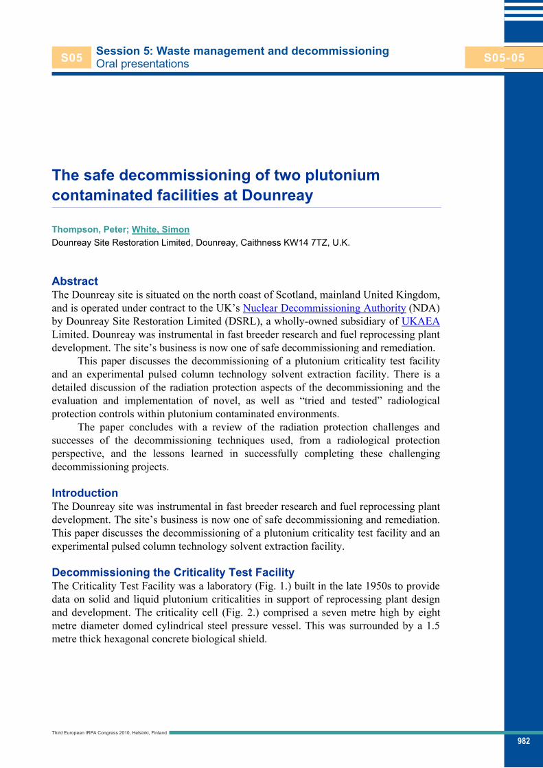
982
Session 5: Waste management and decommissioning Oral presentations
The safe decommissioning of two plutonium contaminated facilities at Dounreay
Thompson, Peter; White, Simon Dounreay Site Restoration Limited, Dounreay, Caithness KW14 7TZ, U.K.
Abstract The Dounreay site is situated on the north coast of Scotland, mainland United Kingdom, and is operated under contract to the UK’s Nuclear Decommissioning Authority (NDA) by Dounreay Site Restoration Limited (DSRL), a wholly-owned subsidiary of UKAEA Limited. Dounreay was instrumental in fast breeder research and fuel reprocessing plant development. The site’s business is now one of safe decommissioning and remediation.
This paper discusses the decommissioning of a plutonium criticality test facility and an experimental pulsed column technology solvent extraction facility. There is a detailed discussion of the radiation protection aspects of the decommissioning and the evaluation and implementation of novel, as well as “tried and tested” radiological protection controls within plutonium contaminated environments.
The paper concludes with a review of the radiation protection challenges and successes of the decommissioning techniques used, from a radiological protection perspective, and the lessons learned in successfully completing these challenging decommissioning projects.
Introduction The Dounreay site was instrumental in fast breeder research and fuel reprocessing plant development. The site’s business is now one of safe decommissioning and remediation. This paper discusses the decommissioning of a plutonium criticality test facility and an experimental pulsed column technology solvent extraction facility.
Decommissioning the Criticality Test Facility The Criticality Test Facility was a laboratory (Fig. 1.) built in the late 1950s to provide data on solid and liquid plutonium criticalities in support of reprocessing plant design and development. The criticality cell (Fig. 2.) comprised a seven metre high by eight metre diameter domed cylindrical steel pressure vessel. This was surrounded by a 1.5 metre thick hexagonal concrete biological shield.
Third European IRPA Congress 2010, Helsinki, Finland
S05 S05-05
S05-05

983
Session 5: Waste management and decommissioning – Oral presentationsThompson, Peter and White, SimonThe safe decommissioning of two plutonium contaminated facilities at Dounreay
Fig. 1. The Criticality Cell during construction Fig. 2. The Criticality Test Facility
By 1994 most of the plutonium inventory process vessels had been decommissioned. The radiological protection aspects of this initial work have been documented in Nicol 1994. The work after this involved the removal of the highly contaminated criticality test cell and decontamination of the building structure before demolition to “brown field” status. This started in 1999 and involved carefully planned pressurised suit entries into the plutonium contaminated criticality cell. The radiological protection aspects of the early phase of this work were reported in Thompson 2002.
Unfortunately the cell contained a large amount of historical waste that had been left over from previous work. This waste was successfully size reduced, packaged and sentenced to the appropriate waste route. The cell’s internal structure (approximately 300m2) was decontaminated using the “sponge jet” technique. This successfully reduced the steel liner from Intermediate Level Waste (ILW) to Low Level Waste (LLW).
Installation of a new ventilation system (designed to be easily removed) was completed to allow the decommissioning of the now 50 year old ventilation system, whilst still providing the required ventilation capability for the remainder of the plants decommissioning. This also involved re-sealing the criticality cell to allow the ventilation capacity to be diverted to support decommissioning of other rooms within the facility. This work was carried out on a room by room basis. On some walls, particularly at locations where wet systems were located, the contamination had penetrated deep into the structure and required complete demolition, as decontamination via scabbling and other methods was not viable. To reduce manual handling, and mitigate radiological and industrial safety hazards much of the demolition was carried out using a Brokk robotic machine (Fig. 3. and Fig. 4.).
Third European IRPA Congress 2010, Helsinki, Finland
S05 S05-05
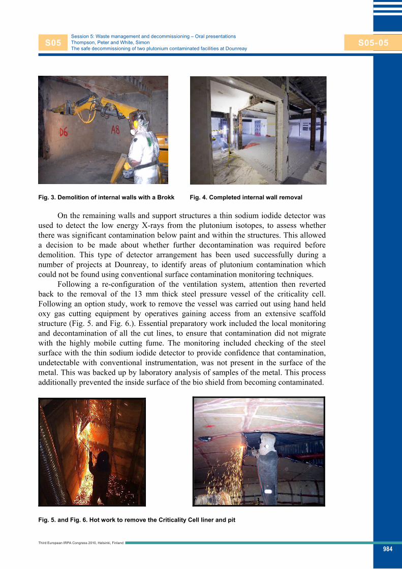
984
Session 5: Waste management and decommissioning – Oral presentationsThompson, Peter and White, SimonThe safe decommissioning of two plutonium contaminated facilities at Dounreay
Fig. 3. Demolition of internal walls with a Brokk Fig. 4. Completed internal wall removal
On the remaining walls and support structures a thin sodium iodide detector was
used to detect the low energy X-rays from the plutonium isotopes, to assess whether there was significant contamination below paint and within the structures. This allowed a decision to be made about whether further decontamination was required before demolition. This type of detector arrangement has been used successfully during a number of projects at Dounreay, to identify areas of plutonium contamination which could not be found using conventional surface contamination monitoring techniques.
Following a re-configuration of the ventilation system, attention then reverted back to the removal of the 13 mm thick steel pressure vessel of the criticality cell. Following an option study, work to remove the vessel was carried out using hand held oxy gas cutting equipment by operatives gaining access from an extensive scaffold structure (Fig. 5. and Fig. 6.). Essential preparatory work included the local monitoring and decontamination of all the cut lines, to ensure that contamination did not migrate with the highly mobile cutting fume. The monitoring included checking of the steel surface with the thin sodium iodide detector to provide confidence that contamination, undetectable with conventional instrumentation, was not present in the surface of the metal. This was backed up by laboratory analysis of samples of the metal. This process additionally prevented the inside surface of the bio shield from becoming contaminated.
Fig. 5. and Fig. 6. Hot work to remove the Criticality Cell liner and pit
Third European IRPA Congress 2010, Helsinki, Finland
S05 S05-05

985
Session 5: Waste management and decommissioning – Oral presentationsThompson, Peter and White, SimonThe safe decommissioning of two plutonium contaminated facilities at Dounreay
The work culminated in a complete radiological survey of the building which included conventional health physics monitoring, plutonium X-ray monitoring and sampling of the building structure before the building was declassified and freed for demolition. Demolition was completed using conventional techniques (Fig. 7.).
The completion of this challenging project removed a significant liability from the site (Fig. 8.) and was a very significant success story for the Dounreay site.
Fig. 7. Demolition of the Criticality Test Facility Fig. 8. The completed project
Decommissioning the Pulsed Column Laboratory The Pulsed Column Laboratory (PCL) was built for full scale reprocessing flow sheet trials, using pulsed column technology (Fig. 9), which was a more efficient solvent extraction process and a replacement for “mixer settler” solvent extraction technology. The laboratory housed a large sectional glass pulsed column rig inside a glovebox with dimensions of 11.5 metres (high) by 6.5 metres (wide) and 1.2 metres (deep) which extended up four floor levels within the building (Fig. 10.).
Fig. 9. Pulsed Columns Fig. 10. The Pulsed Column Laboratory
Third European IRPA Congress 2010, Helsinki, Finland
S05 S05-05

986
Session 5: Waste management and decommissioning – Oral presentationsThompson, Peter and White, SimonThe safe decommissioning of two plutonium contaminated facilities at Dounreay
During the early stages of the decommissioning work (Thompson 2001, Thompson 2002) in the PCL there were a number of low level intakes of radioactive material identified following the provision of nose blow samples. The contamination in the nose blow samples was not accompanied by significant surface contamination or airborne activity monitoring results.
A thorough investigation into the intakes highlighted that the contaminant was likely to be of very small particle size (sub micron) and that this was proving to be a significant challenge to the containment and ventilation system that had been installed for the decommissioning work.
The initial strategy involved breaching the glovebox to remove its internal glassware and services which were then size reduced in a purpose designed glass crusher before being disposed of as ILW. This resulted in a spread of contamination to the laboratory. Although tie down materials and decontamination campaigns were regularly undertaken, the laboratory effectively became the primary containment. It was clear that the contamination in the laboratory was providing a challenge to the ventilation system. To address this, a significant change in strategy was implemented with the fundamental principle being to regain and retain the glovebox as the primary containment.
The following text discusses the improvements that were made to the decommissioning strategy, containment, ventilation and access arrangements.
Ventilation and access/egress arrangements The original ventilation design was set up to draw air through each of the four pressurised suit access corridors to the laboratory. The effectiveness of the ventilation system to provide adequate containment velocities at the containment barriers was sensitive to prevailing external weather conditions and internal movement (opening of doors, etc.) within the facility.
These access arrangements (Fig. 11.) were also convoluted causing problems with turbulent airflow at the containment barriers and curtains. This created a significant challenge to the dynamic containment of the facility, due to poor consistency of face velocities at barriers and turbulence at barriers and barrier curtains.
To improve this situation a number of significant modifications (Fig. 12.) to barrier arrangements and the supply ventilation flow distribution were implemented, including: Sealing of two access floors, which reduced the volumetric flow through these
areas. This provided increased ventilation capacity to support dynamic containment at the two remaining access barriers and increased the volumetric airflow rate through these access areas. The increased volumetric flow rate also allowed the removal of the barrier curtains and barriers without any reduction in the required containment velocity of ~1m/s.
Using prefabricated ‘oval’ doorways (without curtains) and profiling to streamline corners, etc. This reduced the amount of turbulence in the access arrangements and the fluctuating air flows noted during previous decommissioning entries as curtains are opened and closed (Fig. 12.). Furthermore, this modification eliminated the risk of contamination spread onto curtains.
Third European IRPA Congress 2010, Helsinki, Finland
S05 S05-05

987
Session 5: Waste management and decommissioning – Oral presentationsThompson, Peter and White, SimonThe safe decommissioning of two plutonium contaminated facilities at Dounreay
Modification of supply ductwork was necessary to implement improvements to airflow in the main change area, where original duct arrangements resulted in air being blown across the face of the barrier rather than evenly over it. A new supply grill and baffle plate was installed to deliver supply air to the ground floor sub change area and to promote an even flow pattern in the sub change areas.
New supply ducting and ventilation grills were installed to the space ahead of the main change barrier to increase supply volume to the main change area and to promote an even flow pattern over that barrier. To feed these new supply points supply air was transferred from the closed off floors to the ground floor.
Fig. 11. The original PCL access corridor Fig. 12. The improved PCL access corridors
Following implementation of the above, an extensive study of the airflow pattern involving smoke tests, recording and graphing of airflow velocities was carried out. Whilst the barrier flows improved, there was still a need for further improvement. To increase the total extract the power cabling and components for the duty and standby fans were uprated, this included the replacement of the two extract fan motors (duty and standby). To safely take advantage of the increased fan motor power, additional extract capacity was utilised by permanently using all four extract filter banks, as the original plant set up was to use three duty and one standby.
Further inspections and measurements were carried out after the fans were commissioned. Barrier flows were visually inspected using smoke tests generated by an industrial generator. This allowed visual confirmation that the access modifications had resulted in the smoothing of airflow profiles and subsequent much reduced turbulent eddies in the flow characteristics. The smoke tests were replicated with an operator standing at the oval door way which demonstrated that the air flowed past the operator
Third European IRPA Congress 2010, Helsinki, Finland
S05 S05-05

988
Session 5: Waste management and decommissioning – Oral presentationsThompson, Peter and White, SimonThe safe decommissioning of two plutonium contaminated facilities at Dounreay
without any significant backflow being induced. This exercise also proved to be a useful demonstration to the operators of what had been achieved.
Containment The completion of the access arrangements and ventilation improvements allowed re-entry to the laboratory to be made under better conditions. Work to decontaminate the laboratory and re-instate the glovebox containment could now begin. This was achieved by installing a purpose made cover and bag posting arrangements (Fig. 13.) to the open glovebox. This and further covers were installed progressively as the glovebox was emptied and decommissioned (Fig. 14.). Material posted out of the glovebox was via installed bagging ports (Fig. 15.) to be either sentenced as ILW or transferred to the Dounreay decontamination facility for cleaning and disposal as LLW.
Fig. 13. Installation of the PCL Top Hat
Fig. 14. Installed posting ports for the removal of glovebox internals
Third European IRPA Congress 2010, Helsinki, Finland
S05 S05-05

989
Session 5: Waste management and decommissioning – Oral presentationsThompson, Peter and White, SimonThe safe decommissioning of two plutonium contaminated facilities at Dounreay
Fig. 15. Posting operations within the PCL
Development of a new pressurised suit As part of the thorough review of the arrangements at the PCL it was acknowledged that there is a period in the airline suit undressing process, when respiratory protection has to be removed and personnel are not fully protected. To alleviate this issue, a new single use suit with an air fed respirator integrated within the suit was developed (Thompson 2008). This new suit (Fig. 16.) offers the following features:
An air fed respirator integrated within the suit, offering continuous protection both within the suit and following suit removal.
Disposable, offering single use and minimising cross contamination potential.
Improved wearer comfort, when worn with new moisture wicking undergarments.
User involvement (and importantly ‘buy in’) in suit development. Less folds, creases and therefore contamination traps than the two piece suit
that had been used previously. Easy to remove, minimising disturbance of the air and potentially
contamination on removal. The suits were used for the rest of the decommissioning work and proved to be
very popular with the operators. They are very straightforward to put on and remove. It was novel in the United Kingdom for operators to wear respirators inside a pressurised suit, but feedback from the operators has been very favourable as the air fed respirator provides a good flow of air to the head area and has not caused problems with perspiration.
Third European IRPA Congress 2010, Helsinki, Finland
S05 S05-05
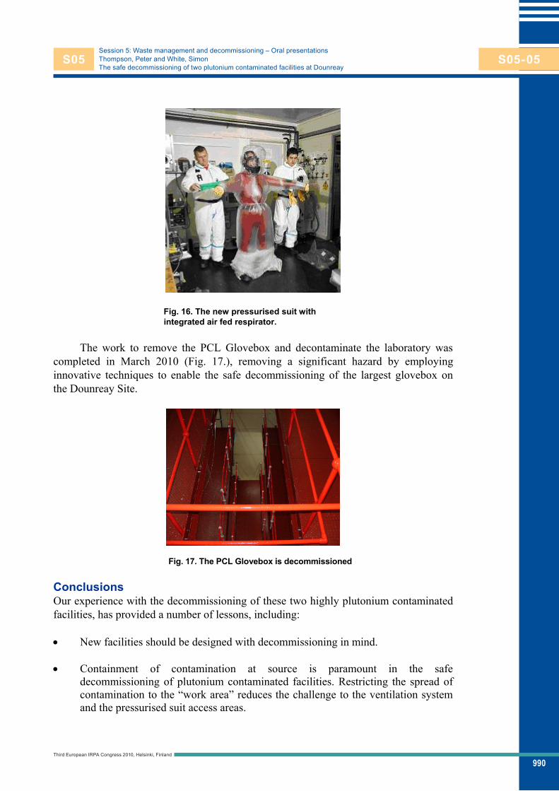
990
Session 5: Waste management and decommissioning – Oral presentationsThompson, Peter and White, SimonThe safe decommissioning of two plutonium contaminated facilities at Dounreay
Fig. 16. The new pressurised suit with integrated air fed respirator.
The work to remove the PCL Glovebox and decontaminate the laboratory was
completed in March 2010 (Fig. 17.), removing a significant hazard by employing innovative techniques to enable the safe decommissioning of the largest glovebox on the Dounreay Site.
Fig. 17. The PCL Glovebox is decommissioned
Conclusions Our experience with the decommissioning of these two highly plutonium contaminated facilities, has provided a number of lessons, including:
New facilities should be designed with decommissioning in mind.
Containment of contamination at source is paramount in the safe
decommissioning of plutonium contaminated facilities. Restricting the spread of contamination to the “work area” reduces the challenge to the ventilation system and the pressurised suit access areas.
Third European IRPA Congress 2010, Helsinki, Finland
S05 S05-05

991
Session 5: Waste management and decommissioning – Oral presentationsThompson, Peter and White, SimonThe safe decommissioning of two plutonium contaminated facilities at Dounreay
Glove boxes should be Post Operative Cleaned Out (POCO) immediately after cessation of work.
Facilities should not be left in care and maintenance for long periods before
decommissioning as facility specific knowledge and experience can be lost. Ventilation system requirements for the decommissioning of plutonium facilities
should take into account potential routine and accidental airborne contamination challenges to the working area. The challenge posed by sub-micron particulate to the containment must be considered. The ventilation system should also be constructed with contingency beyond the minimum calculated requirement to ensure that there is additional capacity available.
To enable unrestricted movement of personnel in and out of the high-risk area, without a significant cross-contamination potential, the space available for ingress and egress should be adequately sized and not convoluted. The addition of barriers and convoluted access ways can also lead to turbulence and the instance of turbulent eddies and back-flow.
A considerable amount of time and effort should be allowed for the final surveys
and decontamination of facilities. The use of instrumentation that measures the low energy X-rays from the plutonium isotopes to assess whether there was significant contamination below paint and within the walls and support structures etc can be extremely useful in the declassification process.
References KAJ Nicol, Health Physics experience in decontamination of a plutonium criticality
assembly Laboratory (Interim Report: October 1987-November 1993), In: Nimmo-Scott W, Golding DJ (Eds.). Proceedings of the 17th IRPA Regional Congress – Portsmouth 6-10 June 1994, pp. 389-392, ISBN 1870965329 (CD ROM).
PJ Thompson et al, International Radiation Protection Association, In: European IRPA Congress 2002, Towards Harmonisation of Radiation Protection in Europe – Florence 8 – 11 October 2002, pp 124-0. IRPA (2002), ISBN 88-88648-09-7 (CD ROM).
PJ Thompson, HJ Pearce, Radiation safety aspects of the “pre-works” for decommissioning the Marshall Laboratories Pulsed Column Laboratory at Dounreay, In: International Conference on Radiation Dose Management in the Nuclear industry, 14-26 May 2001 pp. paper20 Thompson (CD ROM)
PJ Thompson et al, The ‘old and the new’ of decommissioning Dounreay, International Radiation Protection Association, In: IRPA International Congress 12, XXX– Buenos Aires – 19-24 October 2008, pp. 3128, IRPA (2008) (CD ROM)
Third European IRPA Congress 2010, Helsinki, Finland
S05 S05-05
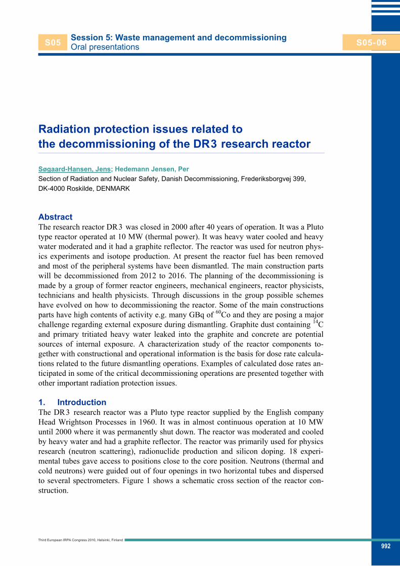
992
Session 5: Waste management and decommissioning Oral presentations
Radiation protection issues related to the decommissioning of the DR3 research reactor
Søgaard-Hansen, Jens; Hedemann Jensen, Per Section of Radiation and Nuclear Safety, Danish Decommissioning, Frederiksborgvej 399, DK-4000 Roskilde, DENMARK
Abstract The research reactor DR3 was closed in 2000 after 40 years of operation. It was a Pluto type reactor operated at 10 MW (thermal power). It was heavy water cooled and heavy water moderated and it had a graphite reflector. The reactor was used for neutron phys-ics experiments and isotope production. At present the reactor fuel has been removed and most of the peripheral systems have been dismantled. The main construction parts will be decommissioned from 2012 to 2016. The planning of the decommissioning is made by a group of former reactor engineers, mechanical engineers, reactor physicists, technicians and health physicists. Through discussions in the group possible schemes have evolved on how to decommissioning the reactor. Some of the main constructions parts have high contents of activity e.g. many GBq of 60Co and they are posing a major challenge regarding external exposure during dismantling. Graphite dust containing 14C and primary tritiated heavy water leaked into the graphite and concrete are potential sources of internal exposure. A characterization study of the reactor components to-gether with constructional and operational information is the basis for dose rate calcula-tions related to the future dismantling operations. Examples of calculated dose rates an-ticipated in some of the critical decommissioning operations are presented together with other important radiation protection issues.
1. Introduction The DR3 research reactor was a Pluto type reactor supplied by the English company Head Wrightson Processes in 1960. It was in almost continuous operation at 10 MW until 2000 where it was permanently shut down. The reactor was moderated and cooled by heavy water and had a graphite reflector. The reactor was primarily used for physics research (neutron scattering), radionuclide production and silicon doping. 18 experi-mental tubes gave access to positions close to the core position. Neutrons (thermal and cold neutrons) were guided out of four openings in two horizontal tubes and dispersed to several spectrometers. Figure 1 shows a schematic cross section of the reactor con-struction.
Third European IRPA Congress 2010, Helsinki, Finland
S05 S05-06
S05-06
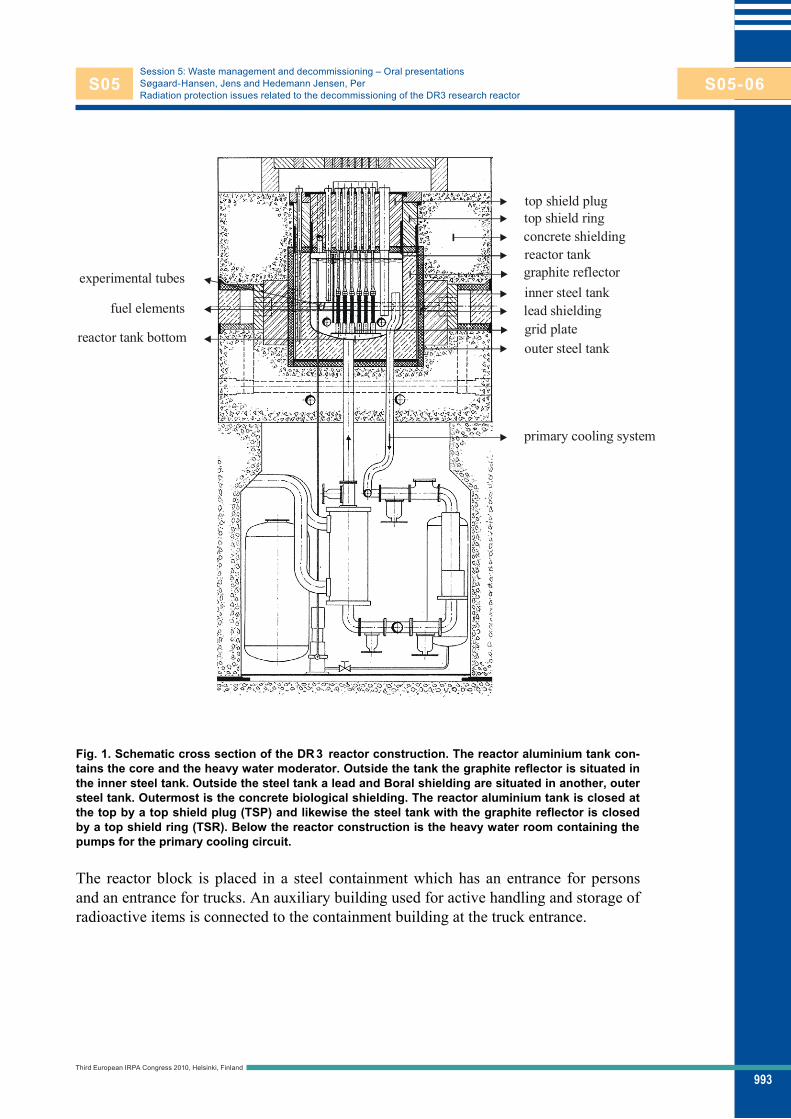
993
Session 5: Waste management and decommissioning – Oral presentationsSøgaard-Hansen, Jens and Hedemann Jensen, PerRadiation protection issues related to the decommissioning of the DR3 research reactor
Fig. 1. Schematic cross section of the DR 3 reactor construction. The reactor aluminium tank con-tains the core and the heavy water moderator. Outside the tank the graphite reflector is situated in the inner steel tank. Outside the steel tank a lead and Boral shielding are situated in another, outer steel tank. Outermost is the concrete biological shielding. The reactor aluminium tank is closed at the top by a top shield plug (TSP) and likewise the steel tank with the graphite reflector is closed by a top shield ring (TSR). Below the reactor construction is the heavy water room containing the pumps for the primary cooling circuit.
The reactor block is placed in a steel containment which has an entrance for persons and an entrance for trucks. An auxiliary building used for active handling and storage of radioactive items is connected to the containment building at the truck entrance.
top shield plug
fuel elements
experimental tubes
reactor tank bottom
top shield ring
graphite reflectorinner steel tank
outer steel tank
primary cooling system
lead shieldinggrid plate
reactor tank concrete shielding
Third European IRPA Congress 2010, Helsinki, Finland
S05 S05-06

994
Session 5: Waste management and decommissioning – Oral presentationsSøgaard-Hansen, Jens and Hedemann Jensen, PerRadiation protection issues related to the decommissioning of the DR3 research reactor
2. Preparing for decommissioning Shortly after the final shut down the fuel was removed and the heavy water was drained from the primary and secondary systems. In 2003 the Danish parliament decided that DR3 (along with the other nuclear facilities at the Risø site) should be decommis-sioned, preferable to a ‘green field’ status and a state company Danish Decommission-ing (DD) was established with a core of personnel from the former nuclear safety de-partment at the Risø National Laboratory.
In 2004 to 2005 a characterization project was carried out [Ølgaard 2006] with the aim of determining the amount of activity in the primary reactor systems and in the concrete in the reactor block.
From 2005 to 2006 another characterization project [Ølgaard et al. 2007] charac-terized the activity contents in components situated in the DR3 storage facilities.
From 2006 and to the end of 2010 the peripheral reactor systems i.e. systems out-side the reactor block are or will be dismantled and removed, leaving the bare reactor block and equipment necessary for the decommissioning e.g. the crane in the contain-ment.
The decommissioning planning for the DR3 started in 2008 and will continue un-til the actual decommissioning takes place from 2012 to 2016. Experience gained from the decommissioning of the DR1 and DR2 reactor will be used (Ingemann Larsen et al. 2008).
3. Radiation protection issues Many radiation protection issues will arise during the decommissioning of the DR3 re-actor. Below some of the most important issues are addressed.
3.1 Radiation protection personnel The Section of Radiation and Nuclear Safety at DD includes four health physicists (HP) and 11 health physics technicians (HPT). The personnel have a comprehensive educa-tion and training in radiation protection (Lauridsen 2009). Several have experience from former reactor operation and most have experience from the decommissioning of the DR1 and the DR2 reactors that were on the site.
The section serves all radiation protection works at DD including a 24 hour on site presence of a HPT. During the preparatory and planning phase 1.5 HP and 1 HPT has been allocated directly to the DR3 decommissioning project. Additional manpower has been used for clearance measurements on equipment from the peripheral system parts. When the DR3 decommissioning starts it is foreseen that 2 HP and 2-3 HPT will be al-located.
3.2 Sources of radiation and contamination From the characterization project and some additional measurements the activity con-centration and total activity content in the different reactor components have been as-sessed. Table 1 gives the values of 60Co (which is the dominating source of external ex-posure) in some of the components primo 2012. The uncertainties on the values are es-timated to be 20-200%, as they are obtained by sampling, which need not to be fully representative.
Third European IRPA Congress 2010, Helsinki, Finland
S05 S05-06
995
Session 5: Waste management and decommissioning – Oral presentationsSøgaard-Hansen, Jens and Hedemann Jensen, PerRadiation protection issues related to the decommissioning of the DR3 research reactor
Table 1. Assessed average activity concentrations and total activity of 60Co in selected reactor component primo 2012.
Component Average activity concentration [MBq/kg]
Total activity [GBq]
Reactor tank (Al), lower part 80 30
Reactor tank (Al), bottom part 55 10
Experimental tubes 55 15
Grid plate 80 10
Graphite reflector 5 65
Inner steel tank, lower part 23 190
Outer steel tank, lower part 2.3 6.6
Top shield plug, bottom iron plate 7300 2200
Top shield ring, bottom iron plate 1300 300
3.3 Planning A group of 10 people including one HP is responsible for the decommissioning plan-ning. This group has expertise within reactor operation, reactor physics, mechanical en-gineering, radiation protection and decommissioning. All the group members have a ba-sic understanding of radiation protection. The group has held one meeting every month from the end of 2007 and two meetings every month from the end of 2008.
Based on knowledge of the reactor construction and the activity contents in the construction parts, critical radiation protection elements in the project have been identi-fied. Some of these have required additional sampling and measurements.
The group has produced preliminary plans for major steps in the decommissioning of the reactor some of which are alternative ways of dismantling. When the preliminary plans have been evaluated, the group will decide for a final decommissioning scheme and a detailed plan will then be made. The planning group will also participate in the actual decommissioning.
Plans are discussed and presented within the Dido Group which has members from other nuclear facilities with a Dido or a Pluto type reactor (Harwell, Dounray, Jülich and Ansto). Also an international expert panel has commented on some of the preliminary plans and will look thoroughly on the final overall plan as will the Danish radiation protection authorities.
3.4 External exposure To assist the planning and evaluation of plans in terms of dose and shielding costs, ra-diation transport calculations have been made using the Monte Carlo method (MCNP) and the point kernel method (summation of point source responses). In cases where both methods have been used good agreements have been obtained. Figure 1 and Figure 2 show MCNP-calculated dose rates primo 2012 at different heights above the bottom of an open reactor pit, with only the top shield plug removed. Dose rates are shown as a function of distance to the central reactor axis. In the Figure 1 calculations air was in the reactor tank while in the Figure 2 calculations water filled up most of the reactor
Third European IRPA Congress 2010, Helsinki, Finland
S05 S05-06
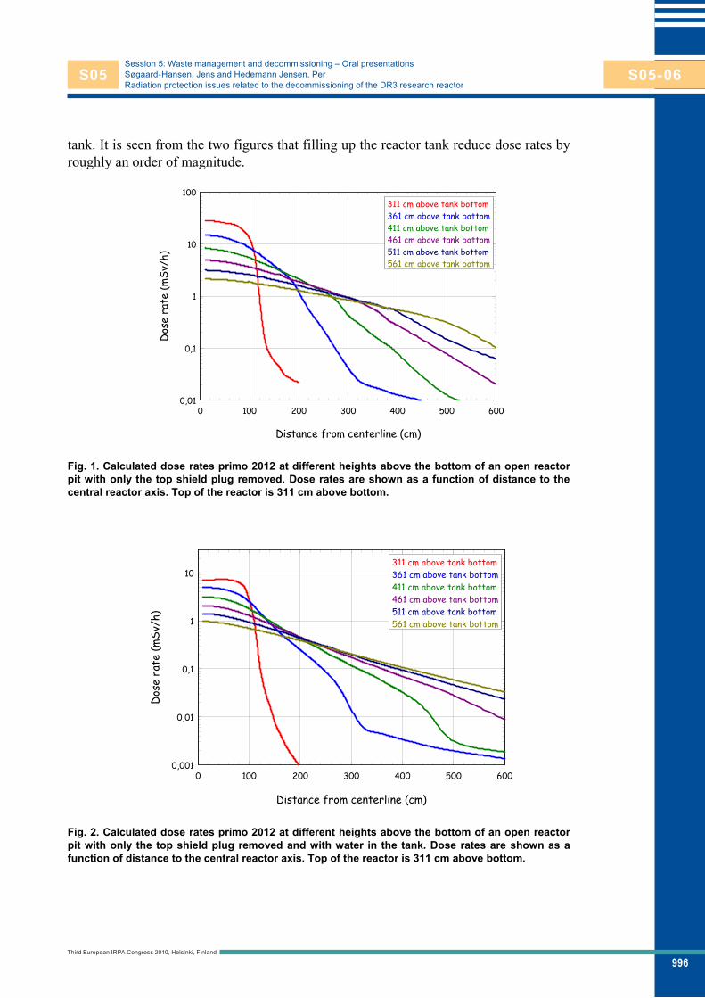
996
Session 5: Waste management and decommissioning – Oral presentationsSøgaard-Hansen, Jens and Hedemann Jensen, PerRadiation protection issues related to the decommissioning of the DR3 research reactor
tank. It is seen from the two figures that filling up the reactor tank reduce dose rates by roughly an order of magnitude.
Distance from centerline (cm)
0 100 200 300 400 500 600
Dos
e ra
te (m
Sv/h
)
0,01
0,1
1
10
100311 cm above tank bottom361 cm above tank bottom411 cm above tank bottom461 cm above tank bottom511 cm above tank bottom561 cm above tank bottom
Fig. 1. Calculated dose rates primo 2012 at different heights above the bottom of an open reactor pit with only the top shield plug removed. Dose rates are shown as a function of distance to the central reactor axis. Top of the reactor is 311 cm above bottom.
Distance from centerline (cm)
0 100 200 300 400 500 600
Dos
e ra
te (m
Sv/h
)
0,001
0,01
0,1
1
10311 cm above tank bottom361 cm above tank bottom411 cm above tank bottom461 cm above tank bottom511 cm above tank bottom561 cm above tank bottom
Fig. 2. Calculated dose rates primo 2012 at different heights above the bottom of an open reactor pit with only the top shield plug removed and with water in the tank. Dose rates are shown as a function of distance to the central reactor axis. Top of the reactor is 311 cm above bottom.
Third European IRPA Congress 2010, Helsinki, Finland
S05 S05-06

997
Session 5: Waste management and decommissioning – Oral presentationsSøgaard-Hansen, Jens and Hedemann Jensen, PerRadiation protection issues related to the decommissioning of the DR3 research reactor
3.5 Internal exposure The induced activity contents in the reactor components constitute sources of internal exposure as the dismantling will require the use of cutting tools. In addition a leak in the primary cooling system has supposedly coursed a widespread contamination with tritiated heavy water in especially the graphite and the concrete shielding. Also it is ex-pected that graphite dust is already present some places in the graphite. From the esti-mated contents of radionuclides in the different reactor components the potential for in-ternal exposure has been calculated. Table 2 gives the mass concentration in air equiva-lent to an effective dose rate of 1 Sv/h. Conservative activity to effective dose conver-sion factors have been used and tritium contents due to leakage has not been taking into account. For materials containing more than one radionuclide, the equivalent masse concentration is calculated as: where Ci is the concentration of nuclide i in the material (Bq/kg) and dci is the activity concentration in air (Bq/m3) of nuclide i which is equivalent to an effective dose rate of 1 Sv/h. Table 2. Mass concentrations in air of different reactor materials equivalent to a dose rate of 1 Sv/h.
Reactor material Equivalent mass concentration in air ( kg/m3)
Graphite reflector 1.4
Al reactor tank 0.4
Steel inner tank 1.4
Concrete shielding 30
Primary heavy water 0.2
3.6 Dose constrains and acceptable doses Dose constrains will be set for individual doses for each of the years the decommission-ing takes place. The dose constrain for effective dose will be in the interval 5-10 mSv pr. year depending on the operations planned for the particular year. For all years the equivalent dose to the eyes will be constrained to 15 mSv/year and the equivalent dose to skin and to extremities will be constrained to 150 mSv/year.
Due to the inherent associated large uncertainties in determining internal doses, planning should strive to entirely avoiding internal exposure with tritium as an excep-tion.
Radiation doses below the dose constrains should be as low as reasonably achiev-able. To assist the more detailed planning in controlling exposure for individual opera-tions a guideline on “acceptable doses” has been made. Table 3 gives values of accept-able doses for operations with different benefit and frequency.
1Cidcii
Third European IRPA Congress 2010, Helsinki, Finland
S05 S05-06
998
Session 5: Waste management and decommissioning – Oral presentationsSøgaard-Hansen, Jens and Hedemann Jensen, PerRadiation protection issues related to the decommissioning of the DR3 research reactor
Table 3. Guideline for “acceptable doses” from working operations.
Benefit from operation and frequency of opera-tion (pr. year)
“Acceptable” effective dose
“Acceptable” equivalent dose
to eyes
“Acceptable” equivalent dose to skin
and extremities
Small benefit, high frequency up to 10-20 Sv up to 30-60 Sv up to 300-600 Sv
Medium benefit, high frequency up to 50 Sv up to 150 Sv Up to 1500 Sv
Large benefit, low frequency up to 100-200 Sv up to 300-600 Sv Up to 3000-6000 Sv
Very large benefit, A few operations Up to 500 Sv up to 1500 Sv up to 15000 Sv
Very large benefit, one operation Up to 2000 Sv up to 6000 Sv up to 60000 Sv
3.7 Clearance An infrastructure for clearance called the Clearance Function has been established with-in the Section of Radiation and Nuclear Safety. This Function comprises laboratory fa-cilities, measuring equipment, measuring procedures, waste handling software, software for clearance related calculations and trained personnel (Søgaard-Hansen et al 2008). The Clearance Function was granted an accreditation in 2007 from the accreditation body, DANAK, according to the standard ISO/IEC 17025 (ISO 2005). The accredita-tion process was completed over a period of approximately one year. Many of the items from the peripheral systems have been classified as candidates for clearance measure-ments and have subsequently been cleared; in contrast all materials within the reactor block are to be considered as radioactive waste.
4. Conclusions The Section of Radiation and Nuclear Safety at DD which has been in existence since the days of reactor commissioning will be responsible for the radiation protection guid-ance during the decommissioning project. Procedures used during reactor operation such as participation of health physics personnel in planning and execution of opera-tions which involve high dose rates and/or risk of contamination and health physics classification of areas will be continued during the decommissioning phase.
From the assessed activity contents the radiation exposure during the various op-erations will be calculated and used in the planning of the operations, with adequate considerations taken to allow for large uncertainties on the activity estimates. Calcula-tions will, when possible, be checked with measurements.
A guideline for acceptable doses has been communicated to the planning group to help the detailed planning in ensuring that the dose constrains are respected.
References Ingemann Larsen T, Hedemann Jensen P, Søgaard-Hansen, Lauridsen B. Radiation Pro-
tection Measures During the Decommissioning of DR2. Proceedings of IRPA12 2008 October 19-24; Buenos Aires, Argentina.
Third European IRPA Congress 2010, Helsinki, Finland
S05 S05-06

999
Session 5: Waste management and decommissioning – Oral presentationsSøgaard-Hansen, Jens and Hedemann Jensen, PerRadiation protection issues related to the decommissioning of the DR3 research reactor
ISO/IEC 17025:2005. General Requirements for the Competence of Testing and Cali-bration Laboratories. Brussels: CEN/GENELEC 2005.
Lauridsen B, Silva J. Education of Health Physicists and Health Physics Technicians at Danish Decommissioning. Proceedings of the 4th. International Conference on Education and Training in Radiological Protection. 2009 November 8-12; Lisbon, Portugal.
Søgaard-Hansen J, Hedemann Jensen P, Ingemann Larsen T, Lauridsen B. An Accred-ited Infrastructure for Clearance of Decommissioning Waste. Proceedings of IRPA12 2008 October 19-24; Buenos Aires, Argentina.
Ølgaard PL. The DR3 Characterization Project. DD-23(EN). Roskilde: Danish De-commissioning; 2006.
Ølgaard PL, Hjerrild Nielsen K. The Characterization Project for the DR3 Storage Fa-cilities. DD-31 (EN). Roskilde: Danish Decommissioning; 2007.
Third European IRPA Congress 2010, Helsinki, Finland
S05 S05-06

1000
Session 5: Waste management and decommissioning Oral presentations
Alara aspects in dismantling of the irradiated fuel reprocessing pilot Plant MTR Type (M1 Plant)
Ruiz Martínez, José Tomás1; Gutierrez Moratal, José Miguel2; Zurita Montero, Antonio3 1 LAINSA S.A.U, SPAIN 2 LAINSA S.A.U, SPAIN 3 MONCOBRA S.A.U , SPAIN
Abstract The irradiated fuel reprocessing plant MTR type was designed to treat fuel elements plate type from reactor JEN-1 (Ciemat). This facility (M-1 Plant) also served to develop fuel reprocessing processes.
Dismantling Works, which have been conducted by ENRESA, were carried out by MONCASA-LAINSA ( MONLAIN) , the most experienced Spanish joint venture in dismantling nuclear facilities.
The dismantling of M-1 plant was performed from 2007 until the beginning of 2008.
This paper presents the performed dismantling works of the three M-1 Plant main systems:
Hot Cell M-1. Glove Boxes Assembly L-1. Radioactive Liquid Waste Storage Cell (F-1).
The dismantling of these systems required methodical tasks planning, development of specific execution processes, execution of Alara studies and detailed safety plans.
Development of specific tools for dismantling tasks, containment auxiliary systems design, namely ventilated tents with local extraction systems and HEPA filters, operation assembly for equipment and components’ extraction represent ones of the examples presented in this work.
A multidisciplinary team formed by the two companies joint venture, working together on an equipment designed by ENRESA, has carried out a unique work in Spain, executed with efficiency, optimizing resources and wastes, and minimizing the dose in accordance with the Alara criteria.
Introduction The pilot plant for reprocessing of irradiated fuel type MTR (Plant M-1) is located in the eastern part of CIEMAT, in Building 18. It was designed to treat plaque-type fuel elements of the JEN-1 reactor and for the development of fuel reprocessing processes.
Third European IRPA Congress 2010, Helsinki, Finland
S05 S05-07
S05-07

1001
Session 5: Waste management and decommissioning – Oral presentationsRuiz Martínez, José Tomás et al.Alara aspects in dismantling of the irradiated fuel reprocessing pilot Plant MTR Type (M1 Plant)
After two campaigns of treatment of irradiated fuels the Plant was shut down. The dismantling of the facilities of the Plant M-1 has been performed in the frame
of the Integrated Plan for the Improvement of the Facilities of the Ciemat ( PIMIC The dismantling of these systems has needed careful planning of tasks,
development of specific execution procedures, and performance of Alara studies and detailed Safety Plans.
Description of the plant
Fig. 1. Layout of the M1 Plant.
The pilot plant for reprocessing of irradiated fuel type MTR (Plant M-1) is a building of 352 m2 and 6 m high, divided into three modules, with two floors in the central module.
The areas of interest for this paper are on the ground floor and northern area (Figure 1): Glove box chain L-1 and M1 Hot cell and outside the building 18, F-1 cell, Liquid Radioactive Waste Storage.
Glove Box Chain L-1 It contains the medium and low activity process equipment. The glove box chain L-1 has an "L" shape with seven separate modules. The second and the third are joined in a unique module.
The modules are divided in two parts. The low part of the second, third and sixth modules are not a part of the glove box and were used for the installation of auxiliary material. Each module is made of a metal profile structure to which panels of methyl-methacrylate (Plexiglas) of 8 mm of thickness are mate and constitute the side faces, as
Third European IRPA Congress 2010, Helsinki, Finland
S05 S05-07

1002
Session 5: Waste management and decommissioning – Oral presentationsRuiz Martínez, José Tomás et al.Alara aspects in dismantling of the irradiated fuel reprocessing pilot Plant MTR Type (M1 Plant)
well as the separation between modules. The funds, roofs and separations between areas of modules are sheets of steel of 5 mm thick.
Cell M-1 Inside the cell the equipment for the first cycle of uranium and plutonium separation is found. Having dimensions of 1.60 x 4.80 x 2.40 m. The ceiling and walls of the cell M-1 are composed of reinforced concrete with a thickness of 65 cm. Part of the front wall (1.2 x 4 m) is shielded with three layers of lead bricks 50 mm thick. In the right side wall of the cell there is an opening that gives access to the interior with a free surface of 1.70 x 0.70 m, which is closed by a staggered shape door made of 60 cm thick barite concrete.
The M-1 cell contains diverse equipments of the first purifying fuel cycle, including tanks, mixers, settlers, valves and interconnecting tubing, mainly.
On the roof of the cell M-1 are found: the shielded glove box (sampling system of the cell deposits) and shielded cubicle C-1 (filtration system of the main process) and C-2 (volumetric pumps remote heads feeding radioactive solutions to process equipment).
Cell F-1 The F-1 cell for the reception and temporary storage of radioactive liquid waste is an underground cell of 2.6 x 4.5 x 4 m with reinforced 40 cm thick concrete walls. The roof is 20 cm above the street level and consists of 6 concrete slabs of 40 cm thick, which allows access to the interior.
The cell is divided internally into two areas, by means of barite concrete blocks (density 3.3 g / cm ³) with a thickness of 50 cm, in order to separate the reception and storage of high and intermediate liquid effluents activity to the reception and storage of those of low activity.
The storage area of high and intermediate liquid effluents activity contains the tank A-1 (high activity), A-2 and A-3 (intermediate activity). The area of low activity includes tanks B-1 and B-2.
Dismantling Works Planning for decommissioning has been carried out with reference to data provided ENRESA in the technical specification. The work was divided into units of intervention and for each of them a dismantling card was prepared to collect data related to the radiation risks, radioactive inventory, list of materials depending on their typology, estimate of waste, radiation protection and safety, equipment, components and systems, etc.
The first stage consisted of preparing the auxiliary facilities, in particular containment enclosures, called SAS (Figure 2). Due to the risk of alpha contamination the need to use a double barrier of containment was considered. This SAS consisted of a double enclosure, internal and external SAS, with an exhaust system that ensured an air flow towards the interior and that was complemented by a HEPA filtering system.
Third European IRPA Congress 2010, Helsinki, Finland
S05 S05-07

1003
Session 5: Waste management and decommissioning – Oral presentationsRuiz Martínez, José Tomás et al.Alara aspects in dismantling of the irradiated fuel reprocessing pilot Plant MTR Type (M1 Plant)
Fig. 2. SAS of Glove Boxes L-1.
The internal SAS had rectangular form and covered all the glove boxes L1 for both sides. It consisted of a metallic structure covered by methacrylate in the lower and not protected areas.
The external SAS covered the half of the room where there were the glove boxes L1 and the entry of the M1 cell. It was placed, partly, on the cell M1 and the rest in the corridor between M1 cell and the south wall. It had a metallic structure and it was covered in most cases by methacrylate. It is necessary to clarify that in the low part a door of methacrylate was enabled to allow the access to the waste management area.
That area had two methacrylate doors: one of them, in the East side, allowed the entrance of the wastes and the other was in the West side where the waste left. A rotary alarm with a door blocking system was placed to avoid the two doors were opened at the same time.
The system of assisted breathable air for the pressurized suits of the staff was located at the entrance area from inside the room, in the SAS of staff.
Dismantling of glove boxes L-1. First, ancillary equipment (mixer-settler) located at the bottom of the modules C2, C3 and C6 was removed. The retrieval of these elements to the metallic containers was done by double bagging.
Next, sampling systems, glass columns (filled with silica gel), elements of ventilation and separate items mounted inside the box in the upper level of the modules C2, C3, C4, C5 and C6 were dismantled.
The method used to extract these systems from the inside of the glove boxes was the bagging.
Then dismantling of ducts, capping and closure of the holes, and connections with the lower level boxes C2, C3 and C6, was done.
Once emptied out the items with the previous method, and sealing the connections pipes, we proceeded to clean the inside (mopped) prior to the implementation of fixing paint inside the boxes.
HOT CELLM-1
ENTRYEXITSTAFF
C.M.T.
EXITWASTES
L1-SAS
Third European IRPA Congress 2010, Helsinki, Finland
S05 S05-07

1004
Session 5: Waste management and decommissioning – Oral presentationsRuiz Martínez, José Tomás et al.Alara aspects in dismantling of the irradiated fuel reprocessing pilot Plant MTR Type (M1 Plant)
Then we proceeded to the dismantling of the conduits located on the roof of the glove boxes L1, using cutting techniques such as confined cutting or sealed cutting with polyurethane foam.
Once the boxes were painted, the fastening pieces and methacrylate sheets were removed and cut to adapt them to the size of the metallic container.
Tanks on the lower level of each of the glove boxes were cleared. Funds, ceilings, separating plates of 5 mm thick steel, and metal profiles were
dismantled by cold cutting.
Hot Cell M-1 Once the Glove Box L-1 dismantled, it was necessary to restructure the SAS (see figure 3), to adapt it for the dismantling of the Cell M1.
Fig. 3. SAS of Hot Cell M-1.
Given that the there was little room inside the Cell and the expected dose rates in certain systems, it was necessary to plan the works in detail attending on the ALARA principle.
An inventory of the equipments and systems of the interior of the Cell was performed, and a few cards reflecting the relevant information of every component (radiological characteristics, situational scheme inside the cell) were prepared.
A few auxiliary systems were prepared: Vacuum of particles. Decontamination. Collection of liquids Plasticized and bagging. Shielding. Mechanical manipulation of loads. Supply of breathable air.
Third European IRPA Congress 2010, Helsinki, Finland
S05 S05-07
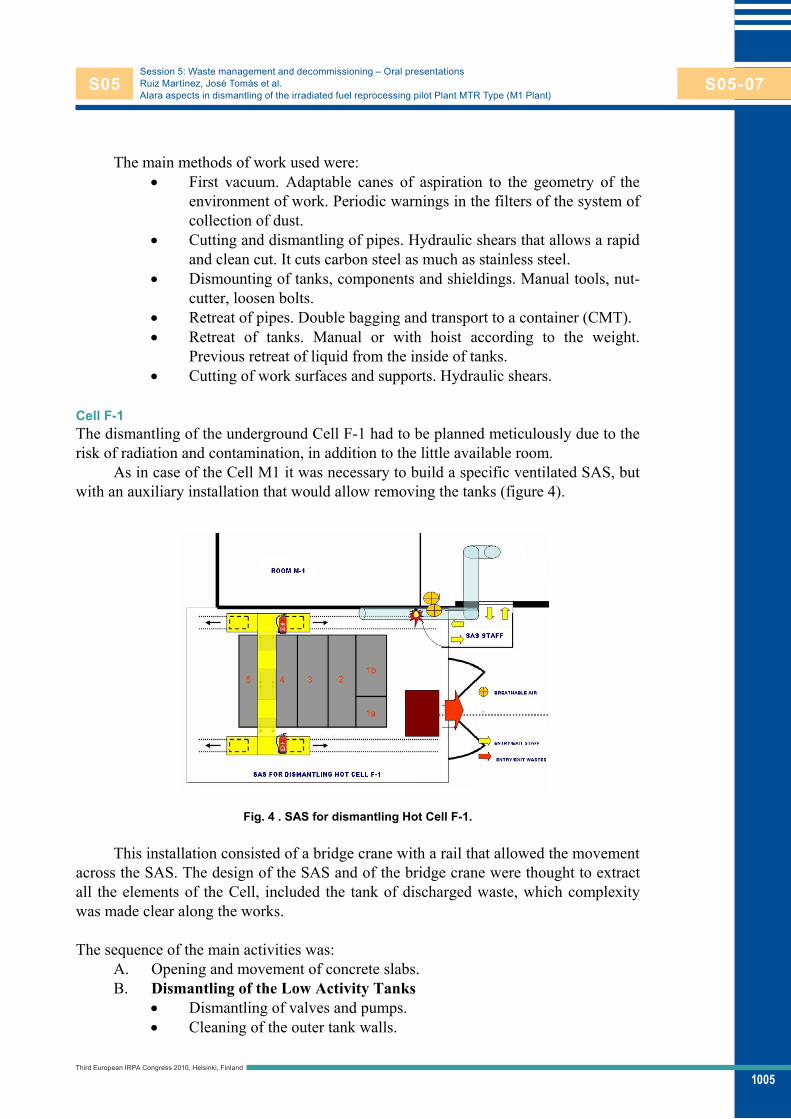
1005
Session 5: Waste management and decommissioning – Oral presentationsRuiz Martínez, José Tomás et al.Alara aspects in dismantling of the irradiated fuel reprocessing pilot Plant MTR Type (M1 Plant)
The main methods of work used were: First vacuum. Adaptable canes of aspiration to the geometry of the
environment of work. Periodic warnings in the filters of the system of collection of dust.
Cutting and dismantling of pipes. Hydraulic shears that allows a rapid and clean cut. It cuts carbon steel as much as stainless steel.
Dismounting of tanks, components and shieldings. Manual tools, nut-cutter, loosen bolts.
Retreat of pipes. Double bagging and transport to a container (CMT). Retreat of tanks. Manual or with hoist according to the weight.
Previous retreat of liquid from the inside of tanks. Cutting of work surfaces and supports. Hydraulic shears.
Cell F-1 The dismantling of the underground Cell F-1 had to be planned meticulously due to the risk of radiation and contamination, in addition to the little available room.
As in case of the Cell M1 it was necessary to build a specific ventilated SAS, but with an auxiliary installation that would allow removing the tanks (figure 4).
Fig. 4 . SAS for dismantling Hot Cell F-1.
This installation consisted of a bridge crane with a rail that allowed the movement across the SAS. The design of the SAS and of the bridge crane were thought to extract all the elements of the Cell, included the tank of discharged waste, which complexity was made clear along the works.
The sequence of the main activities was:
A. Opening and movement of concrete slabs. B. Dismantling of the Low Activity Tanks
Dismantling of valves and pumps. Cleaning of the outer tank walls.
Third European IRPA Congress 2010, Helsinki, Finland
S05 S05-07

1006
Session 5: Waste management and decommissioning – Oral presentationsRuiz Martínez, José Tomás et al.Alara aspects in dismantling of the irradiated fuel reprocessing pilot Plant MTR Type (M1 Plant)
Cutting of pipes and supports of the tanks. Application of fixed paint on accessible surfaces of the tank. Hoisted of the tanks. Application of fixed paint in the rest of tank surfaces. Partial cutting of tanks inside the cell and the rest of cuttings outside.
With vacuum hood system. Vacuum and cleaning inside the cell.
C. Dismantling of Intermediate Activity Tanks Extraction of side wall of concrete blocks adjacent to High Activity
tanks. Dismantling of the roof blocks and cutting of feeding pipes of the
tanks. Sealed-cutting of drainage pipes. Hoisted tank. Application of the first layer of fixation. Application of the second layer of fixation. Plasticized. Hoisted and laying in CMT of the tanks.
D. Dismantling of the High activity tank Extraction and dismantling of concrete blocks and cutting of feeding
pipes. Opening a hollow and refilled with a layer of concrete the bottom of
the tank. Fastening and hoisting the tank a little. Application of the first layer of
fixation. Application of the second layer of fixation and covering with plastic. Hoisted of the tank and laying in shuttle. Introduction in spécial container CE2A.
Results Next there the most important results, related to the work load, the dose and the management of materials are presented.
Work load A whole of 4.427 hours x person has been used to achieve the three activities described previously. That indicates the difficulty of the above mentioned works. The percentage distribution of the hours is shown in figure 6. The percentages are very similar in the Cell M1 and in the F-1 and there do not move away too much of those of the glove boxes. Although the radiation risks glove boxes were very lower than those of other systems, certain time was used in the preparatory works, principally in the assembly of the SAS. In case of the Cell M1, the construction of the SAS did not take so much time, since the principal part, the separation in two halves of the Room M1 was already done in the previous phase.
Third European IRPA Congress 2010, Helsinki, Finland
S05 S05-07

1007
Session 5: Waste management and decommissioning – Oral presentationsRuiz Martínez, José Tomás et al.Alara aspects in dismantling of the irradiated fuel reprocessing pilot Plant MTR Type (M1 Plant)
Fig. 5 . Work Load Breakdown.
Management of materials Table 1. Balance of materials.
CLEARENCE Materials RADIAOCTIVE WASTES
Glove Boxes L-1 60 % 15 %
Hot Cell M-1 39% 40 %
Hot Cell F-1 1 % 45 %
Total 100 % 100 %
The whole of treated materials has been 62 Tm approximately. Table 1 shows the
percentage distribution between the glove boxes and the cells for the potentially clearance materials and the radioactive wastes. 17 per cent of the materials have separated as clearance and therefore they have had to surrender to a process of measurement in the box counter, to perform a detailed radiological characterization and to decide his final destination. 83 % remaining has been considered to be radioactive residues, which is coherent with the type of elements on those who have been worked.
As it was expected the percentage of clearance materials for L-1 compared to those the Cells has been very higher. The biggest percentage of residues has been of the Cell F-1, due to the weight of the tanks and to that it has not been possible to segregate any more clearance components, due to the high dose rate inside the Cell.
Dosimetry The activities with important collective dose have been the ones related to the Cell M-1 and the Cell F-1, since in case of the glove boxes L-1, the biggest risk was that of contamination. In this sense, there has been nor external contamination of the personnel neither internal contamination due to the applied confinement and protection measures. Photograph 4 shows the exit of personnel of the SAS of the Cell M1.
The biggest percentage of the collective dose has been allocated to the dismantling of the Cell F-1, as it was expected, since the levels of radiation were high.
Glove Boxes L-1; 28%
Hot Cell M-1; 39%
Hot Cell F-1; 33%
Third European IRPA Congress 2010, Helsinki, Finland
S05 S05-07

1008
Session 5: Waste management and decommissioning – Oral presentationsRuiz Martínez, José Tomás et al.Alara aspects in dismantling of the irradiated fuel reprocessing pilot Plant MTR Type (M1 Plant)
Next the Cell M-1, since although the area dose rate was not too high, nevertheless it was certain equipments having points with high values.
The total collective dose in the Cell M1 has been 6 mSv x person approximately. This dose is 3 times lower than what had been foreseen in the Alara studies. We can find the cause of this deviation in the reduction of the time of execution, for what the exposition has diminished considerably. The detailed planning previous to the works has been a key point in this sense.
In case of the Cell F-1, the total collective dose has been 10 mSv x person. It represents approximately twice less than the expected one. In this case the attenuation of the term source, by means of shieldings and the meticulous planning of the works have been the main reasons.
Conclusions The intervention of a multidisciplinary team of two constituent companies of the JV, collaborating with the team designated by ENRESA, has reached very good results in a work in Spain considered as unique. This work has been performed in an efficient and effective form, optimizing resources and residues and minimizing the doses in accordance with the Alara principle.
This work had not been possible without the fundamental support of the CIEMAT in the execution of the operations.
References Ruiz JT, Zurita A, Maza JA. Desmantelamiento de la planta piloto de reproceso de
combustibles irradiados tipo MTR ( Planta M1). Revista Sociedad Nuclear Española 2009; Nº 301 : page 44.
ENRESA. Especificación de Desmantelamiento de la Zona Este del emplazamiento. Proyecto de Desmantelamiento de Instalaciones del Ciemat ( PIMIC).T00-MEC-201. 2006.
Third European IRPA Congress 2010, Helsinki, Finland
S05 S05-07

1009
Session 5: Waste management and decommissioning Oral presentations
Protocol for the clearance and release for metal materials from SLAC National Accelerator Laboratory – Application to BaBar Detector Dismantling
Liu, James1; Fasso, Alberto1; Kerimbaev, Emil1; Rokni, Sayed1; Sabourov, Amanda1; Vollaire, Joachim1; Yamanishi, Hirokuni2
1 SLAC National Accelerator Laboratory, UNITED STATES 2 National Institute for Fusion Science, JAPAN
Abstract In 2000, the DOE announced a suspension on unrestricted releases of any metals that have been inside a radiological area. SLAC is an electron accelerator facility which has many valuable metal components for off-site reuse or recycling. BaBar is a particle physics detector currently being dismantling for that purpose. Based on the DOE relief process, a protocol for unrestrictive release of non-radioactive metals is developed for BaBar dismantling.
At electron accelerators, surface contamination is very unlikely and volume activation is the main interest. The BaBar protocol can be generalized for other applications at SLAC or other electron accelerators. The SLAC protocol consists of an evaluation to determine the potential radioactivity of metal components based on process knowledge, calculations and measurements, as well as a technical basis for unrestrictive release.
Facility operations (beam or non-beam related) that can potentially contaminate or activate property are evaluated as follows: 1) obtaining process knowledge such as BaBar historical operational models and beam losses, 2) radioactivity calculations using the FLUKA Monte Carlo code, which allows a zoning approach to classify the components as radioactive or not for the purposes of planning, radiological control, and measurements, and 3) gross beta-gamma field survey on all surfaces of every item. Gamma spectroscopy measurements are conducted on pre-determined critical items to compare with FLUKA results.
The technical basis for the protocol consists of determining the detection limits of the measurement methods. Survey procedures and release criteria are developed based on the DOE Order 5400.5, MARSSIM, and ANSI standard N13.12. The SLAC instrument’s detection limit is 10 times lower than the N13.12 clearance level for volumetrically activated materials based on the dose of 1 mrem/yr. Only items that have non-detectable radioactivity from both calculations and measurements will be released.
Third European IRPA Congress 2010, Helsinki, Finland
S05 S05-08
S05-08

1010
Session 5: Waste management and decommissioning Oral presentations
Development of radiochemical analytical method for the determination of radionuclides difficult to measure for decommissioning of nuclear facilities
Hou, Xiaolin Technical University of Denmark, Risø National Laboratory for Sustainable Energy, DENMARK
Abstract The decommissioning of a nuclear facility requires estimating the total inventory of radioactivity in various materials and its variation with time, which has to be carried out by the determination of the radioactivity of various radionuclides presented in the materials. The neutron activation products of components and impurity in the materials, such as 3H, 14C, 36Cl, 41Ca, 60Co, 55Fe, 63Ni, 133Ba, 152Eu, 154Eu, and some transuranics, are the main contributors to the total radioactivity. But some fission products, such as 90Sr, 99Tc, 129I, and 137Cs, may also exist in the materials due to the contamination of the leaked nuclear fuel. Of these radionuclides, the beta and alpha emitters including 3H, 14C, 36Cl, 41Ca, 55Fe, 63Ni, and some transuranics, have to be determined by radiochemical analysis including a completely separation of individual radionuclides from matrix and other radionuclides before measurement by beta counting, alpha spectrometry or mass spectrometry. This work presents various radiochemical analytical methods developed in the authors laboratory in the recent years for the determination of these radionuclides in various materials for the decommissioning of nuclear facilities, which includes: 1. rapid determination of tritium and 14C in solid materials, such as graphite,
concrete, steel, aluminium, paint, silica gel, soil, and dust; 2. determination of 14C in high tritium samples, such as heavy water, waste water,
and oil; 3. determination of 36Cl and 129I in graphite, steel, concrete, waste water, and dust; 4. determination of 41Ca in concrete; 5. determination of 55Fe and 63Ni in graphite, concrete, steel, aluminium, sediment,
sand, waste water, seawater, and lichens.
Third European IRPA Congress 2010, Helsinki, Finland
S05 S05-09
S05-09
1011
Topic 5: Waste management and decommissioning Poster presentations
Meaning of site-specific data in dose assessment: case of concentration ratios in boreal forest
Ikonen, Ari T. K.1; Aro, Lasse2; Helin, Jani1 1 Posiva Oy, Olkiluoto, FI-27160 Eurajoki, FINLAND 2 Finnish Forest Research Institute, Parkano Unit, FI-39700 Parkano, FINLAND
Abstract Posiva is implementing a deep repository for spent nuclear fuel in Olkiluoto, Finland. A site-specific safety case is being produced, and data has been acquired for the assessment models. However, neither site or literature data alone are sufficient for the safety case; a balanced combination is needed. The case of the concentration ratios from soil to plants in boreal forest, dominant ecosystem at the site, is discussed in this contribution.
Combining literature data with site data is not straightforward. Our approach is based on updating probability density functions (pdf). First, an a priori distribution is established from site-applicable literature data to contribute to the width of the distribution. Then, the pdf is updated with individual, site-relevant literature data taking into account the number of samples as a weight. Finally, the distribution is updated with the site data. In the weighting, also additional weighting factors of confidence or relevance for which quantitative measures have been established can be used. Repeating the procedure for different groupings of data, e.g. plant types, reveals whether the grouping is statistically reasonable.
The meaning of the site data is pronounced where the site data alone is not sufficient and where the literature data would have not been adequate: few site data do not necessarily reveal the entire width of the distribution, and the literature data may not span to the extremes in the site data.
Furthermore, the national forest soil inventory methodology applied required development of a concept to calculate concentration ratios from multi-layer soil data where the rooting depth is taken into account, as opposed to the conventional method of average concentration in soil core to a fixed depth. Examples of concentration ratios specific to soil layers are presented.
Introduction Posiva is implementing a deep repository for spent nuclear fuel in Olkiluoto, Finland. A site-specific safety case is being produced to support a construction license application in 2012 (Posiva 2008), and data has been acquired for the assessment models (Hjerpe et al. 2010). In the assessment, a large amount of data is required of which only part can
Third European IRPA Congress 2010, Helsinki, Finland
P05 P05-01
P05-01

1012
Topic 5: Waste management and decommissioning – Poster presentationsIkonen, Ari T. K. et al.Meaning of site-specific data in dose assessment: case of concentration ratios in boreal forest
be produced in the site investigations with reasonable resources. Furthermore, there has been discussion on whether the site data alone would be sufficient anyway since it may not capture the entire variability relevant to the assessment (e.g. Sheppard 2005), the less the fewer the site data is. In this paper, methods to derive concentration ratios from site data and to combine site and literature data are outlined and demonstrated, and the need of site-specific and generic data is discussed based on some examples.
In Posiva's repository programme, ecosystem characterisation is an iterative process aiming to achieve an adequate site understanding, in order to evaluate the appropriateness of different models and of preliminary data to the site, and subsequently to provide data of sufficient scope and quality to underpin the safety case development (Haapanen et al. 2009). Ideally, a totally exhaustive characterisation of the properties and processes of the ecosystem could be taken as the aim. However, with any limited resources that can never be achieved, neither is it necessary to achieve to present a sufficient safety case; the extent of the ecosystem characterisation efforts needs to be in reasonable relation to the overall repository programme, the significance to the safety of the spent fuel disposal and the regulatory requirements. In practice, this means continuous improvement at a moderate level (i.e., reasonable in the context of overall repository programme) in ecosystem characterisation with a focus on issues that have significant safety relevance. Identification of key issues is not a straightforward task, but an iterative process, preferably done with feedback from the regulator and other stakeholders. During the initial overall characterisation little data has been acquired in some key nuclides and their chemical analogues – the programme is currently shifting focus from the general characterisation to these assessment-driven key issues. In the interim, information also from other programmes of similar sites or literature needs to be utilised.
Material and methods
Multi-layer approach to concentration ratios In Posiva's biosphere assessment BSA-2009 (Hjerpe et al. 2010), the terrestrial ecosystems are represented by a compartment model shown in Figure 1. The model has been reformulated from earlier ecosystem-specific compartment models to correspond the features at the site as recognised in the biosphere description process (Haapanen et al. 2009). Following from its specific function and on the other hand its varying thickness (about 2-20 cm in the rather young sites at Olkiluoto Island, emerged from sea by post-glacial uplift only during few past millennia), the humus layer has been separated from the underlying mineral soil layers in forest objects. The compartment structure is also consistent with the available information from the various site studies, where the humus layer, the mineral soil layer of 0...30-cm depth and the subsoil are sampled separately to follow more general sampling schemes (e.g. the national forest soil inventory), and in the case of subsoil also in separate campaigns with lower spatial resolution due to the need of machinery and the disturbance to the site studied.
Third European IRPA Congress 2010, Helsinki, Finland
P05 P05-01
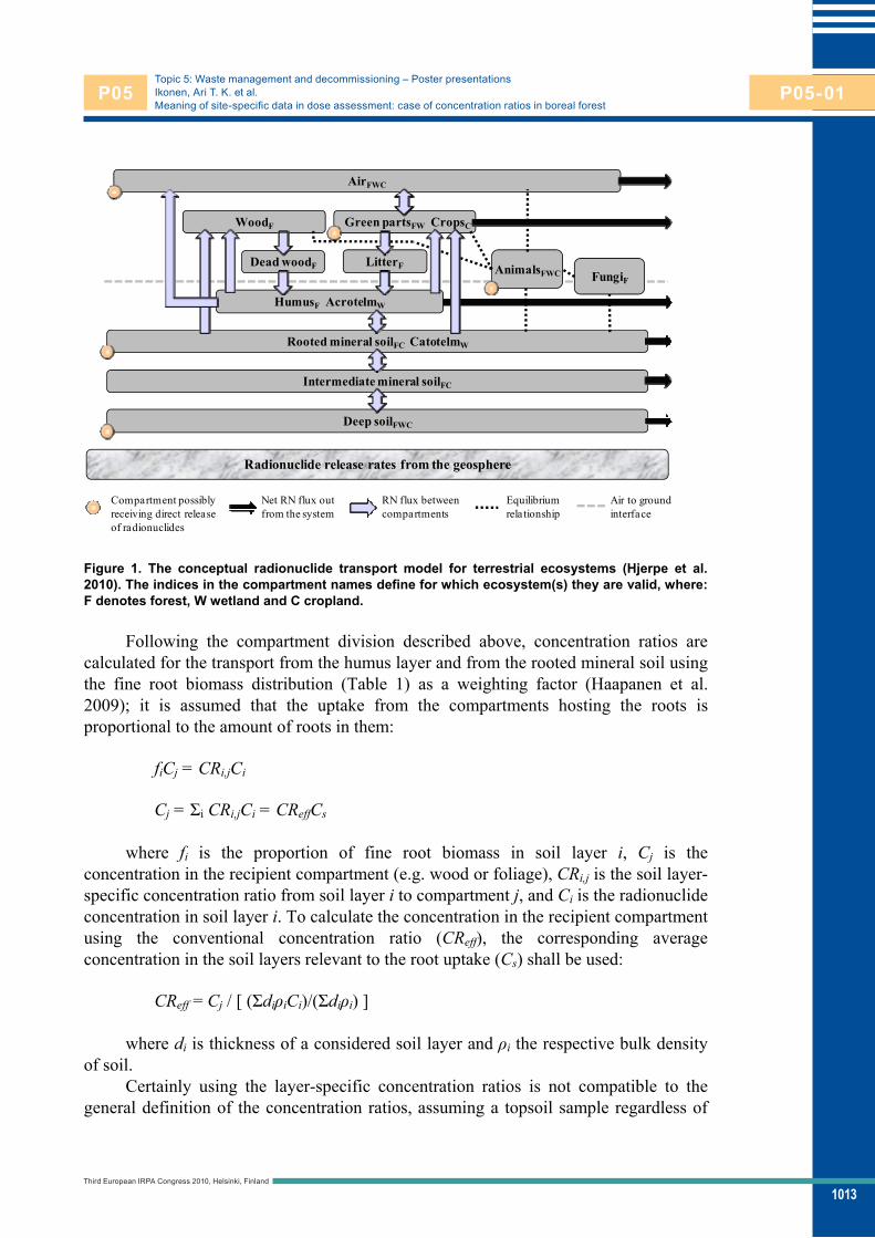
1013
Topic 5: Waste management and decommissioning – Poster presentationsIkonen, Ari T. K. et al.Meaning of site-specific data in dose assessment: case of concentration ratios in boreal forest
Deep soilFWC
Intermediate mineral soilFC
Rooted mineral soilFC CatotelmW
Green partsFW CropsC
AnimalsFWC FungiF
WoodF
Dead woodF LitterF
AirFWC
HumusF AcrotelmW
Radionuclide release rates from the geosphere
Net RN flux out from the system
RN flux between compartments
Equilibrium relationship
Compartment possibly receiving direct release of radionuclides
Air to ground interface
Figure 1. The conceptual radionuclide transport model for terrestrial ecosystems (Hjerpe et al. 2010). The indices in the compartment names define for which ecosystem(s) they are valid, where: F denotes forest, W wetland and C cropland.
Following the compartment division described above, concentration ratios are calculated for the transport from the humus layer and from the rooted mineral soil using the fine root biomass distribution (Table 1) as a weighting factor (Haapanen et al. 2009); it is assumed that the uptake from the compartments hosting the roots is proportional to the amount of roots in them:
fiCj = CRi,jCi
Cj = i CRi,jCi = CReffCs
where fi is the proportion of fine root biomass in soil layer i, Cj is the concentration in the recipient compartment (e.g. wood or foliage), CRi,j is the soil layer-specific concentration ratio from soil layer i to compartment j, and Ci is the radionuclide concentration in soil layer i. To calculate the concentration in the recipient compartment using the conventional concentration ratio (CReff), the corresponding average concentration in the soil layers relevant to the root uptake (Cs) shall be used:
CReff = Cj / [ ( di iCi)/( di i) ]
where di is thickness of a considered soil layer and i the respective bulk density of soil.
Certainly using the layer-specific concentration ratios is not compatible to the general definition of the concentration ratios, assuming a topsoil sample regardless of
Third European IRPA Congress 2010, Helsinki, Finland
P05 P05-01

1014
Topic 5: Waste management and decommissioning – Poster presentationsIkonen, Ari T. K. et al.Meaning of site-specific data in dose assessment: case of concentration ratios in boreal forest
the soil layers, most often 30 cm. Thus for comparisons or combination with literature data, CReff needs to be estimated and used.
Table 1. Distribution of fine root biomass (mass-%) in humus layer and in mineral soil layer of 0-30 cm at Olkiluoto (Helmisaari et al. 2009).
Stand type Plant group Humus Min. soil Application in assessment
Pine Trees 38 62 Pine trees
Pine Shrubs 85 15 Shrubs in coniferous stands
Pine Grasses 89 11 Grasses and herbs in pine stands
Spruce Trees 59 41 Spruces and coniferous bushes
Spruce Grasses 99 1 Grasses and herbs in spruce stands
Birch Tree seedlings 71 29 Deciduous trees and bushes
Birch Shrubs 63 37 Shrubs in deciduous stands
Birch Grasses 76 24 Grasses and herbs in deciduous stands
Combination of various data sources using Bayesian updating A Bayesian approach has been developed by Kristofer Stenberg (Facilia AB) and adopted by Posiva (Helin et al. 2010) to obtain combined probability density functions (pdf) from site measurements and literature data. The goal is to obtain pdf's that take into account the more generic data when the site data is judged insufficient and also the variability between the studies included.
As a ratio quantity, concentration ratios are expected (and thus assumed) to be lognormally distributed by the central limit theorem. Most data compilations that have studied the form of the distribution do not represent arguments against the assumption, although some other possible distributions have been derived from the data.
For small number of observations there can be large uncertainty in the estimates of mean and variance. Bayesian updating makes it possible to reduce this uncertainty by including further knowledge (prior knowledge) in the estimation: a prior distribution of the two unknown parameters is assumed and the posterior distribution, or the probability of the parameters conditioned on observed data, is given by Bayes' theorem. There are different methods of estimating the posterior distribution depending on the interpretation of the prior knowledge and thereby on the form of the prior specification. In this paper we demonstrate only combining the site and literature data with direct updating where they are considered equally appropriate to the site: the posterior is a combination of the observations a priori and the new observations, weighted with the sample sizes. This method utilises the concept of full conjugacy of the prior distribution (Gelman et al. 2003). This and the other methods, population and hierarchical updating, are described in more detail in (Helin et al. 2010).
Results
Soil-layer-specific concentration ratios from the Olkiluoto site Table 2 lists results on concentration ratios of nickel and iodine to forest plants, derived from the data from three sampling sites at Olkiluoto in 2008: FIP4, FIP10 and
Third European IRPA Congress 2010, Helsinki, Finland
P05 P05-01

1015
Topic 5: Waste management and decommissioning – Poster presentationsIkonen, Ari T. K. et al.Meaning of site-specific data in dose assessment: case of concentration ratios in boreal forest
FEH914254 (Haapanen 2009). FIP (forest intensive monitoring) plots have been established to continuously follow changes taking place in the nutrient budgets and fluxes in the soil, tree stands and vegetation at both the stand and the catchment level. FIP4 is a Scots pine-dominated advanced growing stand and FIP10 is a mature Norway spruce-dominated stand. Both FIP plots are located in herb-rich heath forests. FEH plots are used for inventories of vegetation (composition, biomass, nutrient concentrations) and soil (soil profile description, physical and chemical properties) at 5–10 years intervals, in addition to regular tree stand measurements. FEH914254 is a black alder-dominated stand growing on herb-rich heath forest site.
As an example of a larger dataset, for comparison, respective concentration ratios of nickel are presented in Table 3 as derived from a forest inventory at Olkiluoto in 2005 (Tamminen et al. 2007). Further details of the calculations can be found in (Ikonen et al. 2010).
Combinations of site and literature data To illustrate the combination of datasets using the Bayesian direct updating described above, datasets on concentration ratios of iodine to plants are used (the choice was limited by availability of literature data comparable to the site data). The site data on effective concentration ratios to understorey plants (excluding mosses) presented in Table 2 and Fig. 1 was combined with concentration ratios to generic plants derived by Sheppard et al. (2006). The latter data was converted to the dry-weight basis by assuming a dry matter content of 0.50 kgdw/kgfw. The combined data, still dominated by the literature data (N=80 vs. N=7 of the site data), exhibits a slightly higher geometric mean following from the update with the site data having a higher geometric mean than the literature data. The geometric standard deviation has also increased in the combination due to the difference of the datasets; in the combined one the variability of the both original datasets has been included.
Fig. 1. Distributions of concentration ratios of iodine ([kg/kgdw]/[kg/kgdw]): site-specific data for understorey (CReff, Table 2), data for generic plants (Sheppard et al. 2006) and their combination derived by Bayesian direct updating. Geometric means are presented by end of the thick bars and 5th and 95th percentiles as the lines.
Third European IRPA Congress 2010, Helsinki, Finland
P05 P05-01

1016
Topic 5: Waste management and decommissioning – Poster presentationsIkonen, Ari T. K. et al.Meaning of site-specific data in dose assessment: case of concentration ratios in boreal forest
Table 2. Soil-layer-specific and conventional, or effective, concentration ratios ([kg/kgdw]/[kg/kgdw]) of nickel and iodine to forest plants at Olkiluoto in 2008, geometric mean (geometric standard deviation; number of sample pairs). The humus layer (h) has been taken as the actual at the sampling sites, and the mineral soil layer (min) includes the top 30 cm.
CRh, Ni CRmin, Ni CReff, Ni CRh, I CRmin, I CReff, I
Tree foliage 0.11 (2.9; 3)
0.15 (2.6; 3)
0.31 (3.1; 3)
0.05 (-; 1)
0.14 (-; 1)
0.29 (-; 1)
Grasses & herbs 0.17 (2.8; 5)
0.03 (6.7; 5)
0.35 (1.8; 5)
0.09 (1.7; 5)
0.02 (5.4; 5)
0.28 (1.2; 5)
Bilberry leaves* 0.14 (1.9; 2)
0.03 (1.5; 2)
0.19 (1.3; 2)
0.07 (-; 2)
0.03 (-; 2)
0.16 (-; 2)
Understorey ** 0.15 (2.4; 8)
0.02 (4.5; 8)
0.24 (2.2; 8)
0.08 (1.7; 7)
0.03 (4.0; 7)
0.23 (1.4; 7)
* Vaccinium myrtillus ** All concentration ratios to understorey plants (except mosses) pooled
Table 3. Soil-layer-specific and conventional, or effective, concentration ratios ([kg/kgdw]/[kg/kgdw]) of nickel to forest plants at Olkiluoto in 2005, geometric mean (geometric standard deviation; number of sample pairs). The humus layer (h) has been taken as the actual at the sampling sites, and the mineral soil layer (min) includes the top 30 cm.
CRh, Ni CRmin, Ni CReff, Ni
Tree foliage 0.07 (1.7; 90)
15 (7.3; 80)
3.4 (4.6; 90)
Grasses & herbs 0.15 (1.7; 125)
3.6 (11; 122)
5.8 (4.3; 125)
Bilberry leaves* 0.07 (1.4; 58)
6.3 (4.9; 54)
4.2 (2.5; 58)
Understorey ** 0.10 (2.0; 240)
3.8 (8.3; 223)
4.5 (3.8; 240)
* Vaccinium myrtillus ** All concentration ratios to understorey plants (except mosses) pooled
Table 4. Concentration ratios of iodine to understorey plants in Olkiluoto (Table 2), to generic plant type (Sheppard et al. 2006) and their combination by Bayesian direct updating ([kg/kgdw]/[kg/kgdw]). GM denotes the geometric mean, GSD the geometric standard deviation and N the number of data.
GM GSD N
Understorey 0.23 1.4 7
Generic plant 0.016 9.3 80
Combined 0.02 9.6 87
Discussion If we consider, for example, the transport parameters, like Sheppard (2005), it is indeed nearly impossible to know whether there is an unexpected bias when there are only few data (from the site or the literature), and also to exemplify whether a species in a group is different from another, for example, is bilberry bioconcentrating more effectively than lingonberry? In any case, the more data available, the more we can know about the
Third European IRPA Congress 2010, Helsinki, Finland
P05 P05-01

1017
Topic 5: Waste management and decommissioning – Poster presentationsIkonen, Ari T. K. et al.Meaning of site-specific data in dose assessment: case of concentration ratios in boreal forest
underlying processes and relevant differences in conditions. Since the literature data on these parameters are notoriously scarce (with compendium values usually lacking description of the range of conditions the data are derived from), the contribution of even a few site data would be useful. Still, a few site data alone could be insufficient since the inherent variability of the transport parameters is so large that site data would be significantly different only for "fairly exceptional on-site properties" (Sheppard 2005). Demonstration of such cases turned out to be more difficult in case of forest plants than foreseen; the literature data accessible with moderate effort is rather plenty in caesium data but very scarce for other nuclides, specifically of those most of interest of Posiva's assessment (Cl-36 and I-129, dominating the dose together with C-14 in the dose assessment time window of 10 000 years (YVL 8.4, YVL E-5)).
By comparing the data in Tables 2 and 3 it is notable, that when all forest types in an island of 12 km² are included in the data, the geometric standard deviation (GSD) increases significantly for the concentration ratios from the mineral soil and for the effective concentration ratios this is the opposite to the expected situation with the humus-specific concentration ratios where the GSD decreases with more data. This is likely due to the surrogate data used to the mineral soil layers, practically assuming a default value for each soil type (Ikonen et al. 2010). In the concentration ratios specific to the humus layer this does not affect, and it can be concluded that for foliage and herbs and grasses the GSD decreases to a half with samples increasing from 3-5 to 90-123. With bilberry leaves and understorey in general the change is smaller but exists anyway. In general, it appears that in the larger dataset (Table 3) the humus-specific concentration ratio the values are on the lower end of the 5th-95th percentile range represented by the fewer samples (Table 2) species accumulating more nickel may have been collected into the latter by chance.
Conclusions In the repository programme the ecosystem characterisation provides with data to and supports model development in the dose assessment, and this is an iterative process where focus should be on the parameters which have the highest impact on the doses as only part of the needed input data can ever be acquired by site studies. To ensure that large enough variability is propagated through the assessment, it is necessary to try to identify any bias with help of literature data. However, as the emphasis of radioecology has been almost solely in the consequences of the Chernobyl accident, very little data is available on the radionuclides of interest in the deep geological repository with the naturally occurring nuclides as an exception, which are on the other hand out of the dose assessment time window in the Finnish regulatory context as they may reach the biosphere only after the next glaciation when release constraints apply instead of dose limits. Furthermore, the few compendia data tend to be too general in the description, and the old original research papers are seldom available it is difficult to judge whether a piece of literature data is appropriate to a specific site. All this emphasises the importance of extensive site studies, which should be targeted to cover the variability not only at the site itself but within the full assessment context.
To optimise use of resources, Posiva's approach has been to implement the ecosystem characterisation at the site by adopting methodologies used more widely. By this, large independent datasets become comparable. However, as the sampling and
Third European IRPA Congress 2010, Helsinki, Finland
P05 P05-01

1018
Topic 5: Waste management and decommissioning – Poster presentationsIkonen, Ari T. K. et al.Meaning of site-specific data in dose assessment: case of concentration ratios in boreal forest
analytical protocols have not been tailored to the needs of the radionuclide transport modelling and dose assessment, some gaps remain. For example, in an extensive forest soil inventory, shovel pits are used instead of volumetric samples due to the laboriousness of the latter, and for the integrated benefits humus layer and mineral soil are sampled separately. Calculating traditional concentration ratios from the top 30 cm of soil to the plant needed thus bulk density data for calculating the average concentrations, but few of them are available from the sampling plots. To overcome these difficulties, a concept of multi-layer concentration ratios has been outlined above. With it more of the site data can be utilised, but on the other hand comparison to the traditional concentration ratios in the literature data requires surrogate to the soil density data. This is not seen as a major problem, though, since the literature data is relatively scarce for the most radionuclides of interest of a deep geological repository.
References Gelman A, Carlin J B, Stern H S, Rubin D B. Bayesian data analysis. 2nd edition.
London: Chapman & Hall; 2003. Haapanen A (Ed.). Results of monitoring at Olkiluoto in 2009: Environment. Posiva
Working Report 2009 (45): 272 p. Haapanen R, Aro L, Helin J, Hjerpe T, Ikonen A T K, Kirkkala T, Koivunen S,
Lahdenperä A-M, Puhakka L, Rinne M, Salo T. Olkiluoto Biosphere Description 2009. Posiva Report 2009 (02): 416 p.
Helin J, Hjerpe T, Ikonen A T K. Review of element-specific data for biosphere assessment BSA-2009. Posiva Working Report 2010, in preparation.
Helmisaari H-S, Sah S, Aro L. Fine roots on the intensive forest ecosystem monitoring plots on Olkiluoto Island in 2008. Posiva Working Report 2009 (127): 29 p.
Hjerpe T, Ikonen A T K, Broed R. Biosphere assessment report 2009. Posiva Report 2010 (03): 185 p.
Ikonen A T K, Aro L, Haapanen R, Helin J, Hjerpe T, Kirkkala T, Koivunen S, Lahdenperä A-M, Puhakka L, Salo T. Site and regional data for biosphere assessment 2009. Posiva Working Report 2010, in preparation.
Posiva. Safety case plan 2008. Posiva Report 2008 (05): 80 p. Sheppard S C. Transfer parameters - Are on-site data really better? Human and
Ecological Risk Assessment 2005 (11): 939-949. Sheppard S C, Sheppard M I, Tait J C, Sanipelli B L. Revision and meta-analysis of
selected biosphere parameter values for chlorine, iodine, neptunium, radium, radon and uranium. Journal of Environmental Radioactivity 2006 (89): 115-137.
Tamminen P, Aro L, Salemaa M. Forest soil survey and mapping of the nutrient status of the vegetation on Olkiluoto Island: Results from the first inventory on the FEH plots. Posiva Working Report 2007 (78): 109 p.
YVL 8.4. Long-term safety of disposal of spent nuclear fuel. Helsinki: Radiation and Nuclear Safety Authority; 2001.
YVL E-5. Disposal of nuclear waste. Draft 3, 15.1.2009. Helsinki: Radiation and Nuclear Safety Authority; 2009.
Third European IRPA Congress 2010, Helsinki, Finland
P05 P05-01

1019
Topic 5: Waste management and decommissioning Poster presentations
A graded approach to dose assessment in the Posiva safety case
Hjerpe, Thomas1; Avila, Rodolfo2; Ikonen, Ari T. K.3; Broed, Robert2 1 Saanio & Riekkola Oy, Laulukuja 4, FI-00420 Helsinki, FINLAND 2 Facilia AB, Gustavslundsvägen 151C, SE-16751, Bromma, SWEDEN 3 Posiva Oy, Olkiluoto, FI-27160, Eurajoki, FINLAND
Abstract Posiva Oy is responsible for implementing a final disposal programme in Finland for spent nuclear fuel. The next step of the nuclear licensing is by the end of 2012 submit a construction licence application for a KBS-3 type of repository at the Olkiluoto site. Currently, a safety case is produced to support this application, were a preliminary version was completed in 2009. A three-tiered graded approach was developed and applied in the dose assessment. Tier 1 and 2 are generic screening evaluations, and Tier 3 is based on site-specific state-of-the-art radionuclide transport modelling and dose assessment. The main aim of the screening evaluation is to reduce the number of radionuclides needed to be considered in Tier 3, which is especially valuable for long-term assessments that are associated with large uncertainties. This approach assures that the level of detail of the assessment is appropriate to the magnitude of the potential radiological consequences, and strengthens the confidence in the assessment and the demonstration of compliance with regulatory criteria. Tier 1 derives defensible and extremely cautious Risk Quotients, assuming that all radionuclides released from the geosphere expose one person, or a penalizing species for other biota, without any dispersion in the biosphere. Tier 2 derives defensible and cautious Risk Quotients, based on a generic model including three sub-models, a terrestrial, an aquatic, and a well. The screening evaluation was applied to the geosphere releases derived in the interim safety case. The result shows that 24 of the 35 radionuclides in the geosphere releases can be screened out. Especially noticeable is that no radionuclides in the naturally occurring decay chains need to be propagated to Tier 3. This paper presents the methodology of the graded approach, the screening models, and the results from the screening evaluation in the preliminary safety case.
Introduction Posiva Oy (Posiva) was established in 1995 by the two Finnish nuclear power companies, Teollisuuden Voima Oyj (TVO) and Fortum Power and Heat Oy (Fortum), to implement the final disposal programme for spent nuclear fuel and to carry out the related research, technical design and development. The spent nuclear fuel is planned to
Third European IRPA Congress 2010, Helsinki, Finland
P05 P05-02
P05-02

1020
Topic 5: Waste management and decommissioning – Poster presentationsHjerpe, Thomas et al.A graded approach to dose assessment in the Posiva safety case
be disposed of in a KBS-3 type of repository to be constructed at a depth of about 400 metres in the crystalline bedrock at the Olkiluoto site. Posiva is currently preparing for the next step of the nuclear licensing of the repository, which involves submitting the construction licence application for a spent fuel repository by the end of 2012. A safety case will be produced to support this licence application; the Posiva plan for conducting the safety case is documented in (Posiva 2008).
A key contributor to the safety case is the biosphere assessment. The overall aims of the biosphere assessment are to describe the future, present, and relevant past conditions at, and prevailing processes in, the surface environment of the Olkiluoto site; to model the transport and fate of radionuclides potentially released from the repository through the geosphere to the surface environment; and to assess possible radiological consequences to humans and other biota.
The regulatory requirements for the long-term safety are set out in detail in the Radiation and Nuclear Safety Authority’s (STUK) Guide YVL E.5 (STUK 2009) on disposal of nuclear waste. STUK (2009) states that “In any assessment period, during which the radiation exposure of humans can be assessed with sufficient reliability, and which shall extend at a minimum over several millennia: 1) the annual dose to the most exposed people shall remain below the value of 0.1 mSv, and 2) the average annual doses to other people shall remain insignificantly low”. Furthermore, “disposal shall not affect detrimentally to species of flora and fauna, this shall be demonstrated by assessing typical radiation exposures of terrestrial and aquatic populations in the disposal site environments”.
The main approach in the biosphere assessment is to develop a fully dynamic model for the development of the surface environments, radionuclide transport and radiological consequences analysis. In the dose assessment part of the biosphere assessment, the fate of radionuclides potentially released to the biosphere is assessed with radionuclide transport models and radiological consequences are assessed by deriving radiation doses to humans and other biota. For the dose assessment, a graded approach based on three tiers has been applied. Tier 1 and 2 involve conducting generic evaluations to screen out radionuclides that have insignificant radiological consequences, using two levels of inherent pessimism, and Tier 3 is based on based on site-specific state-of-the-art radionuclide transport modelling and dose assessment. The graded approach to dose assessment has been developed for, and applied in, the recently produced interim safety case (Hjerpe et al. 2010, Posiva 2010). This paper presents the methodology used in the graded approach, the models underpinning the screening evaluation (Tier 1 and Tier 2) and results from the screening evaluation performed in the interim safety case.
Methodology When conducting the biosphere assessment, two important goals are to ensure that the assessment is based on an appropriate level of understanding of the biosphere and its potential behaviour, and that the level of detail of the assessment is appropriate to the magnitude of the potential radiological consequences.
In the biosphere assessment performed for the interim safety case, a three-tiered graded approach is implemented to achieve the goals. The common denominator in tiered approaches is that the complexity and realism are greater for higher tiers
Third European IRPA Congress 2010, Helsinki, Finland
P05 P05-02
1021
Topic 5: Waste management and decommissioning – Poster presentationsHjerpe, Thomas et al.A graded approach to dose assessment in the Posiva safety case
compared with lower tiers. In the present approach, Tier 1 and Tier 2 are generic radionuclide screening evaluations, requiring a minimum of site-specific data. Tier 3, which uses the landscape model, is the most realistic. The approach is to use the results from Tiers 1 and 2 to identify radionuclides that are highly confidently expected to have insignificant radiological consequences, and do not need to be considered in Tier 3. This allows the computationally demanding landscape model used in Tier 3 to focus on key radionuclides. The approach thus avoids the need to obtain Tier 3 data, and evaluate uncertainties in these data, for radionuclides to which the overall assessment results are not sensitive. It also facilitates and strengthens confidence in the biosphere assessment and strengthens the demonstration of compliance with regulatory criteria, especially by increasing the transparency of the biosphere assessment. Furthermore, it provides an instrument for analysing model uncertainties, and providing guidance for the development of the landscape model, and the associated environmental monitoring programme. The landscape model is presented in Hjerpe et al. 2010 and the models used in the screening evaluation are described below.
The screening evaluation This section describes the approach and the models used in the screening evaluation (Tier 1 and Tier 2). The quantity of interest in both tiers is the Risk Quotient (RQ), which is the calculated nuclide-specific dose rate divided by pre-selected Screening Dose Rates (SDR). The approach must be sufficiently cautious so that there is a high degree of confidence that the potential radiological consequences are below the relevant regulatory requirements when the RQ is below 1. The SDR itself must be assigned a value substantially below regulatory dose constraints; how much lower depends on the desired degree of conservatism in the screening evaluation. The approach here is to select the SDR low enough to allow Tier 1 and 2 to screen out individual radionuclides for which the calculated RQ is less than or equal to 1. Two SDRs are used throughout the evaluation: 10-5 mSv for humans, which is two orders of magnitudes below the lowest regulatory annual dose constraint, and 10 Gy/h for the other biota, which is the default generic screening absorbed dose rate in the ERICA Tier 1 (Beresford et al. 2007) and is also recommended by the PROTECT project (Andersson et al. 2008).
The procedure for the screening evaluation is similar to the one recommended in IAEA (2001) for use in assessing the impact of discharges of radioactive substances to the environment, and the models are in line with the recommendation by the ICRP (2000, 2007b) on how to conduct a dose assessment. In Tier 1, an extremely cautious approach is taken, in which it is assumed that a hypothetical individual receives the maximum exposure over one year to the whole integrated release from the geosphere. If the RQ calculated for a specific radionuclide in Tier 1 is greater than 1, then it is necessary to continue to Tier 2. In Tier 2, a screening model is applied that includes a higher degree of realism than the model used in Tier 1, but is still sufficiently cautious for screening purposes. The generic model includes two generic ecosystem-specific sub-models, one terrestrial and one aquatic, and a well sub-model. The screening model used in Tier 2 does not require site-specific parameters and therefore can be called “generic”. If the RQ calculated for a specific radionuclide in Tier 2 is greater than 1, then it is necessary to consider that radionuclide in the site-specific landscape modelling (Tier 3).
Third European IRPA Congress 2010, Helsinki, Finland
P05 P05-02

1022
Topic 5: Waste management and decommissioning – Poster presentationsHjerpe, Thomas et al.A graded approach to dose assessment in the Posiva safety case
Tier 1 The first tier is conceptually illustrated in Figure 1. It is designed to ensure extremely pessimistic RQs, by several orders of magnitude. Thus, radionuclides screened out at Tier 1 are indisputably insignificant for radiological consequences during the biosphere assessment time window. The evaluation regarding humans is carried out by assessing the doses due to each radionuclide in three exposure situations, where the whole integrated release from the geosphere is
• totally routed to one person for intake by ingestion, • totally routed to one person for intake by inhalation, and • transferred to the ground surface and exposes one person externally.
When assessing the dose due to external exposure, it is pessimistically assumed that the whole activity is transferred to one square meter of ground surface; then the external dose rate is, unrealistically, derived by multiplying the activity concentration in the contaminated surface by the dose coefficient for a source distributed over an infinite ground surface. Further, to derive the annual dose due to external exposure, it is assumed that the person is exposed to that dose rate over one year. The highest annual dose from the three exposure situations considered is then divided by the SDR, for humans, to obtain the RQhumans. Thus, Tier 1 is an extension of the integrated radiotoxicity flux that may be used as an indicator of safety.
The evaluation, regarding other biota, is implemented in a somewhat different fashion. Instead of calculating absorbed dose rates to compare with the selected SDR for other biota to obtain the RQbiota, the SDR is used to determine radionuclide-specific environmental media concentration limits (EMCL), based on the ERICA integrated approach (Beresford et al. 2007). The most penalising EMCL for different solid media (soil or sediment) and liquid media (freshwater and marine water) are denoted as EMCLsolid and EMCLliquid, respectively.
Furthermore, it is pessimistically assumed that the habitat for the worst case reference organism has an activity concentration numerically equal to the total integrated activity, for each radionuclide, in the geosphere release. For example, if the integrated activity is 100 Bq and the worst case reference organism habitat is lake water, an activity concentration of 100 Bq/L in the lake water is assumed. The RQbiota is then determined as the highest ratio of the derived activity concentrations in solid media, or liquid media, and EMCLsolid, or EMCLliquid.
In addition, to be even more certain that the RQs are not underestimated, the integrated geosphere release rates used are not corrected for any radioactive decay, but include build-up of progeny radionuclides. This is, of course, a non-physical approach. However, this is deliberate, so that there is no potential for underestimating the contribution either from the parent or from its progeny. The integration takes places over a time window of 15 000 years (from year 2 020 to year 17 020), which is 5 000 years longer than Posiva’s interpretation of the biosphere assessment time window where regulatory dose constraints apply. Thus, this means that one person, or one individual of the limiting reference organism for other biota, is exposed to everything released from the geosphere up to the year 17 020.
Third European IRPA Congress 2010, Helsinki, Finland
P05 P05-02
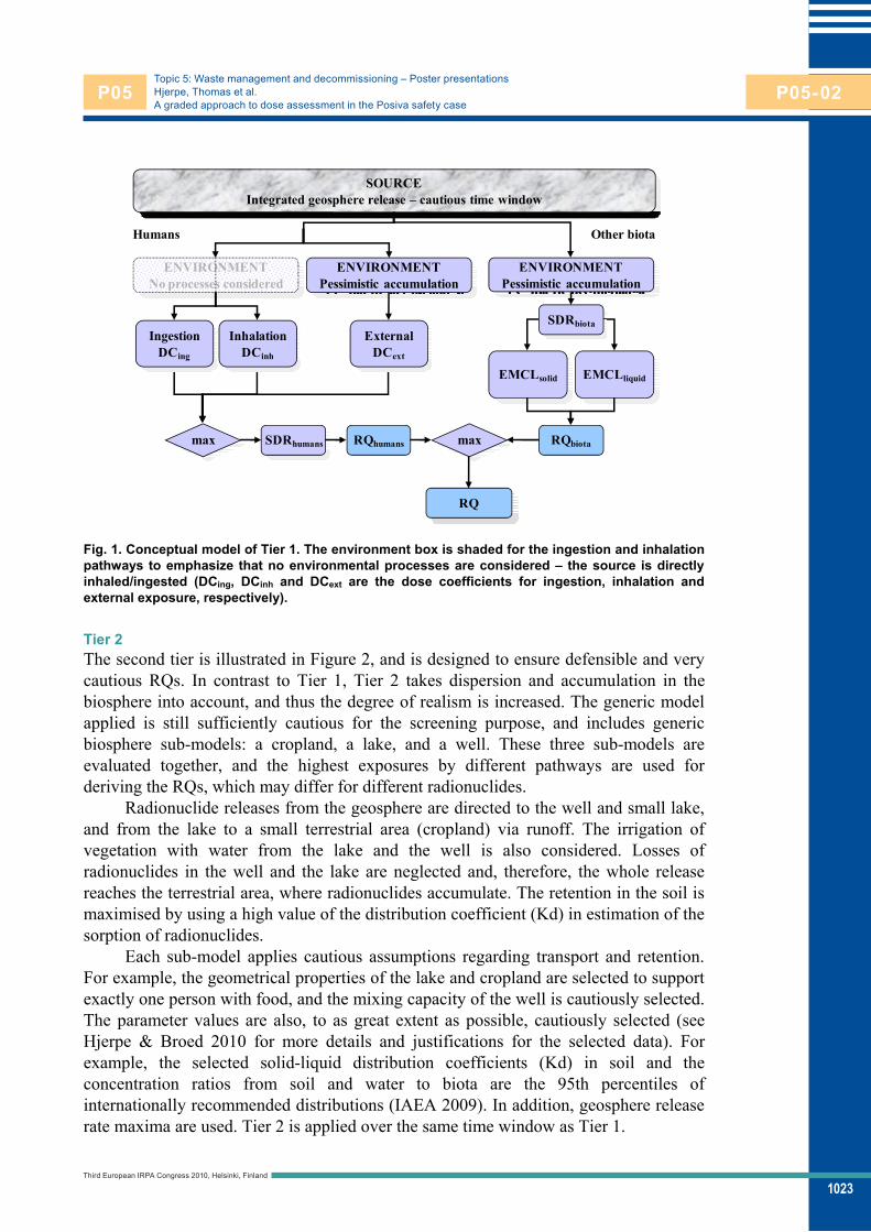
1023
Topic 5: Waste management and decommissioning – Poster presentationsHjerpe, Thomas et al.A graded approach to dose assessment in the Posiva safety case
SOURCEIntegrated geosphere release – cautious time window
max
RQ
ENVIRONMENTNo processes considered
ENVIRONMENTPessimistic accumulation
ENVIRONMENTPessimistic accumulation
Humans Other biota
EMCLsolid EMCLliquid
RQbiotaRQhumans
IngestionDCing
InhalationDCinh
ExternalDCext
max SDRhumans
SDRbiota
Fig. 1. Conceptual model of Tier 1. The environment box is shaded for the ingestion and inhalation pathways to emphasize that no environmental processes are considered – the source is directly inhaled/ingested (DCing, DCinh and DCext are the dose coefficients for ingestion, inhalation and external exposure, respectively).
Tier 2 The second tier is illustrated in Figure 2, and is designed to ensure defensible and very cautious RQs. In contrast to Tier 1, Tier 2 takes dispersion and accumulation in the biosphere into account, and thus the degree of realism is increased. The generic model applied is still sufficiently cautious for the screening purpose, and includes generic biosphere sub-models: a cropland, a lake, and a well. These three sub-models are evaluated together, and the highest exposures by different pathways are used for deriving the RQs, which may differ for different radionuclides.
Radionuclide releases from the geosphere are directed to the well and small lake, and from the lake to a small terrestrial area (cropland) via runoff. The irrigation of vegetation with water from the lake and the well is also considered. Losses of radionuclides in the well and the lake are neglected and, therefore, the whole release reaches the terrestrial area, where radionuclides accumulate. The retention in the soil is maximised by using a high value of the distribution coefficient (Kd) in estimation of the sorption of radionuclides.
Each sub-model applies cautious assumptions regarding transport and retention. For example, the geometrical properties of the lake and cropland are selected to support exactly one person with food, and the mixing capacity of the well is cautiously selected. The parameter values are also, to as great extent as possible, cautiously selected (see Hjerpe & Broed 2010 for more details and justifications for the selected data). For example, the selected solid-liquid distribution coefficients (Kd) in soil and the concentration ratios from soil and water to biota are the 95th percentiles of internationally recommended distributions (IAEA 2009). In addition, geosphere release rate maxima are used. Tier 2 is applied over the same time window as Tier 1.
Third European IRPA Congress 2010, Helsinki, Finland
P05 P05-02

1024
Topic 5: Waste management and decommissioning – Poster presentationsHjerpe, Thomas et al.A graded approach to dose assessment in the Posiva safety case
SOURCEGeosphere release rate maxima – cautious time window
IngestionDCing
InhalationDCinh
ExternalDCext
max
ENVIRONMENTGeneric ecosystem-specific radionuclide transport models
(terrestrial, lake, well)
EMCLsolid/liquid
HABITSCautious assumptions
sum
Other biotaHumans
RQ
RQbiota
RQhumansSDRhumans
SDRbiota
Fig. 2. Conceptual model of Tier 2 (DCing, DCinh and DCext are the dose coefficients for ingestion, inhalation and external exposure, respectively).
Doses are calculated to a hypothetical individual that spends 100% of the time on the contaminated land and is exposed via inhalation and externally. It is assumed that the exposed individual obtains 100% of the ingested water and food from the contaminated environmental media. Moreover, it is assumed that all consumed food and water have the highest calculated activity concentration values.
Results The screening models have been applied to the derived radionuclide release rates from the geosphere to the biosphere, results from repository calculation cases, to screen out the radionuclides considered to be insignificant for the biosphere assessment, from a radiological consequences point of view. The repository calculation cases considered in the screening evaluation mainly originating from the most recent assessment for a KBS-3V repository (Nykyri et al. 2008); but also a few cases are selected from the KBS-3H assessment (Smith et al. 2007) and the earlier assessment for a KBS-3V repository (“TILA-99” Vieno & Nordman 1999). All repository calculation cases addressed have their origin in the same type of repository scenario – assuming releases from a single canister with an initial penetrating defect at the time of emplacement. The full descriptions of the cases are presented in the above-mentioned references. The results from the screening evaluation are presented in Hjerpe et al. (2010) and summarised here, limited to the results from the repository base cases (cases Sh1, PD-BC and SH-sal50) and the cases with the highest derived annual effective doses in the landscape modelling (cases Sh4 Q and PD-EXPELL). This limited set of calculation cases also contains all individual RQ maxima for all cases considered in the dose assessment
Third European IRPA Congress 2010, Helsinki, Finland
P05 P05-02

1025
Topic 5: Waste management and decommissioning – Poster presentationsHjerpe, Thomas et al.A graded approach to dose assessment in the Posiva safety case
performed in the interim safety case, thus the outcome presented below is identical to the outcome that dose assessment.
The resulting RQs from the screening evaluation, for the five repository calculation cases considered here, with Tier 1 are presented in Table 1. At this tier, 11 radionuclides are screened out. The resulting RQs from the screening evaluation, for the five repository calculation cases considered here, with Tier 2 are presented in Table 2. At this tier, an additional number of 13 radionuclides are screened out. The reaming set of radionuclides to consider in Tier 3, and their RQ maxima from the Tier 2 evaluation, are summarised in Table 3.
Discussion The radionuclide releases from the geosphere to the biosphere, in the repository calculation cases considered, contain 35 radionuclides, some also including progeny. At Tier 1, 11 of them are screened out and 13 more are screened out Tier 2, t. The set of remaining 11 radionuclides, and their progeny, is denoted the key set of radionuclides for the biosphere assessment performed for the interim safety case. It is only this set of radionuclides that are considered in Tier 3: the site-specific state-of-the-art radionuclide transport modelling and dose assessment.
It is notable that all actinides and all radionuclides in the naturally occurring decay chains are excluded from the key set of radionuclides (Table 3). However, the applied screening assessment is only valid for the time window where the dose constraints are assumed to apply and for the analysed scenario with a single defective canister. Hence, this does not mean that it is only these 11 radionuclides, and their progeny radionuclides, that are important for long-term safety. A similar screening evaluation carried out beyond the dose assessment time window, or for other scenarios, such as human intrusion, would most likely return another set of radionuclides; in this case, Ra-226 and Pa-231 would certainly be regarded as key radionuclides (see for example the rock shear cases in Nykyri et al. 2008).
Conclusions This paper has presented the methodology for the three-tiered graded approach to dose assessment adapted in the Posiva safety case. Further, results from the successful implementation of the screening evaluation part (Tiers 1 and 2) of the graded approach in the interim safety case have been presented. The outcome shows that by applying a simple screening evaluation, a significant part of the radionuclides existing in the potential releases from the geosphere do not need to be assessed with more realistic, and more complex, biosphere models. Using simple screening models it can be shown with a high confidence that these radionuclides would have insignificant radiological consequences during the time window where the regulatory dose constraints are assumed to apply.
Third European IRPA Congress 2010, Helsinki, Finland
P05 P05-02

1026
Topic 5: Waste management and decommissioning – Poster presentationsHjerpe, Thomas et al.A graded approach to dose assessment in the Posiva safety case
Table 1. Resulting RQs from the Tier 1 screening evaluation.
Radionuclide Sh1 PD-BC SHsal-50 Sh4 Q PD-EXPELL
C-14 5E+07 5E+08 1E+08 8E+08 2E+10
Cl-36 4E+06 3E+08 4E+07 4E+07 9E+08
Ni-59 4E-13 3E-13 2E+03 7E+04 8E-04
Ni-63 6E-12 1E-07
Se-79 3E+00 3E+02 3E+05 3E+01 4E+06
Sr-90+d 9E-09 5E+04 2E+04
Zr-93+d 1E-16 1E-16 1E+00 2E-03
Mo-93+d 3E+00 2E+02 4E+01 3E+09
Nb-94 6E-03 4E-01 7E+02 3E+07 3E+04
Tc-99 7E-18 1E-16 1E+00 2E-03
Pd-107 2E-01 2E+02 1E+01 1E+02 3E+06
Sn-126+d 1E+00 3E+01 3E+07 9E+02 1E+07
I-129 1E+07 5E+08 2E+08 8E+07 1E+09
Cs-135 2E-10 9E-11 6E+03 1E+07 2E-04
Cs-137 3E-07 1E-06
Sm-151 7E-26 3E-09
Pb-210 6E-13 3E-09 4E+03
Ra-226 1E-12 4E-09 7E+03
Th-229 3E-18 3E-16 2E+01
Th-230 2E-18 3E-17 3E+00
Th-232 3E-23 1E-22 1E-07
Pa-231 1E-12 5E-12 5E+05
U-233 2E-19 1E-17 2E+00
U-234 2E-18 2E-17 5E-01
U-235 4E-19 4E-18 4E-03
U-236 1E-17 2E-16 7E-02
U-238 5E-17 5E-18 6E-02
Np-237 2E-17 4E-18 2E-01
Pu-239 2E-12 5E-11 1E+02
Pu-240 1E-12 9E-11 3E+01
Pu-242 2E-14 3E-13 2E+00
Am-241 9E-14 5E-15 2E+01
Am-243 9E-15 9E-16 2E+03
Cm-245 9E-14 3E-15 2E+01
Cm-246 2E-19 9E-21 9E-01
Third European IRPA Congress 2010, Helsinki, Finland
P05 P05-02

1027
Topic 5: Waste management and decommissioning – Poster presentationsHjerpe, Thomas et al.A graded approach to dose assessment in the Posiva safety case
Table 2. Resulting RQs from the Tier 2 screening evaluation.
Radionuclide Sh1 PD-BC SHsal-50 Sh4 Q PD-EXPELL
C-14 1.1E+01 2.5E+02 3.2E+01 2.0E+02 1.6E+04
Cl-36 1.3E+02 1.8E+04 8.1E+02 8.7E+02 1.6E+05
Ni-59 5.0E-17 3.3E-17 3.0E-01 8.1E+00 1.1E-07
Se-79 2.0E-03 2.6E-01 1.7E+02 2.0E-02 2.6E+03
Sr-90 + d 2.9E-11 1.3E+02 4.5E+01
Mo-93+d 5.5E-04 5.0E-02 1.1E-02 1.0E+06
Nb-94 5.8E-09 3.7E-07 7.3E-04 2.9E+01 3.4E-02
Tc-99 3.6E-23 1.8E-21 1.8E-06 5.2E-09
Pd-107 9.2E-06 1.2E-02 3.6E-04 4.3E-03 9.8E+01
Sn-126+d 9.6E-05 3.1E-03 2.0E+03 8.2E-02 7.7E+02
I-129 5.9E+02 7.7E+04 8.6E+03 3.7E+03 6.6E+05
Cs-135 1.7E-12 6.6E-13 4.6E+01 7.9E+04 1.5E-06
Pb-210 4.6E-19 2.1E-15 3.1E-03
Ra-226 1.3E-16 6.0E-13 8.8E-01
Th-229 2.0E-26 1.0E-24 1.6E-07
Th-230 8.1E-27 1.0E-25 5.6E-08
Pa-231 1.2E-19 6.3E-19 5.2E-02
U-233 6.1E-27 1.8E-24 2.1E-07
Pu-239 5.0E-21 2.7E-19 8.6E-07
Pu-240 4.3E-21 5.7E-19 1.9E-07
Pu-242 4.6E-23 1.7E-21 1.4E-08
Am-241 8.4E-22 4.3E-22 1.1E-07
Am-243 9.5E-23 2.3E-23 1.0E-05
Cm-245 1.7E-21 1.5E-22 3.2E-07
Table 3. Resulting set of radionuclides not screened out in the screening evaluation.
Radionuclide RQ maximum In Tier 2
Radionuclide RQ maximum In Tier 2
Mo-93+d 1.0E+06 Sn-126+d 2.0E+03
I-129 6.6E+05 Sr-90 + d 1.3E+02
Cl-36 1.6E+05 Pd-107 9.8E+01
Cs-135 7.9E+04 Nb-94 2.9E+01
C-14 1.6E+04 Ni-59 8.1E+00
Se-79 2.6E+03
Third European IRPA Congress 2010, Helsinki, Finland
P05 P05-02

1028
Topic 5: Waste management and decommissioning – Poster presentationsHjerpe, Thomas et al.A graded approach to dose assessment in the Posiva safety case
References Andersson P, Beaugelin-Seiller K, Beresford NA, Copplestone D, Della Vedova C,
Garnier-Laplace J, Howard BJ, Howe P, Oughton DH, Wells C, Whitehouse P. Numerical benchmarks for protecting biota from radiation in the environment: proposed levels, underlying reasoning and recommendations. PROTECT (Protection of the Environment from Ionising Radiation in a Regulatory Context), EC Project, FI6R-036425. 2008.
Beresford N, Brown J, Copplestone D, Garnier-Laplace J, Howard B, Larsson CM, Oughton D, Pröhl G, Zinger I. (Eds.). D-ERICA: An integrated approach to the assessment and management of environmental risks from ionising radiation - Description of purpose, methodology and application. EC Project, FI6R-CT-2004-508847; 2007.
Hjerpe T, Ikonen ATK, Broed R. Biosphere Assessment Report 2009. POSIVA 2010-03. Olkiluoto; 2010.
International Atomic Energy Agency. Generic models for use in assessing the impact of discharges of radioactive substances to the environment. IAEA Safety Report Series No. 19. Vienna; 2001.
International Atomic Energy Agency. Quantification of Radionuclide Transfer in Terrestrial and Freshwater Environments for Radiological Assessments. IAEA-TECDOC-1616. Vienna; 2009.
International Commission on Radiological Protection. Radiation protection recommendations as applied to the disposal of long-lived solid radioactive waste. ICRP Publication 81. Annals of the ICRP 28(4); 2000.
International Commission on Radiological Protection. Assessing Dose of the Representative Person for the Purpose of Radiation Protection of the Public and the Optimisation of Radiological Protection: Broadening the Process. ICRP Publication 101. Annals of the ICRP 36(3); 2007.
Nykyri M, Nordman H, Marcos N, Löfman J, Poteri A, Hautojärvi A. Radionuclide Release and Transport - RNT-2008. POSIVA 2008-06. Olkiluoto: Posiva Oy; 2008.
Posiva Oy. Safety Case Plan 2008. POSIVA 2008-05. Olkiluoto; 2008. Posiva Oy. Interim Summary Report of the Safety Case 2009. POSIVA 2010-02.
Olkiluoto; 2010. Radiation and Nuclear Safety Authority (STUK). Disposal of nuclear waste. Guide
STUK-YVL E.5. Draft 3, 15.1.2009, in English. 2009. Smith P, Neall F, Snellman M, Pastina B, Nordman H, Johnson L, Hjerpe T. Safety
assessment for a KBS-3H spent nuclear fuel repository at Olkiluoto – Summary report. POSIVA 2007-06 and SKB R-08-39. Olkiluoto: Posiva Oy and Stockholm: Swedish Nuclear Fuel and Waste Management Co (SKB); 2007.
Vieno T, Nordman H. Safety assessment of spent fuel disposal in Hästholmen, Kivetty, Olkiluoto and Romuvaara - TILA-99. POSIVA 99-07. Helsinki: Posiva Oy; 1999.
Third European IRPA Congress 2010, Helsinki, Finland
P05 P05-02

1029
Topic 5: Waste management and decommissioning Poster presentations
On a simple method for proving clearance conditions for radioactive waste
Toro, Laszlo1; Stafie, Adrian2
1 Institute of Public Health Timisoara, MateFin Ltd. Bucharest, Radiation Hygiene Department, ROMANIA 2 Cernavoda NPP, ROMANIA
Abstract Radioactive waste is one of the main problems of nuclear power. Any unusable material (waste) occuring in a part of a nuclear power plant is considered radioactive waste. An important part of these wastes have very low radioactivity, it may be excluded from the system of the radioactive waste regulation. Exclusion of a material from the regulation of radioactive waste is based primarily on a series of measurements to demonstrate the radioactive elements in the material are under the exclusion limits set by law. This paper presents a methodology including a series of relatively simple measurements which prevents time and human resources consuming radiochemical separation procedures. The basic idea is the fact that it is not necessary to know the exact amount of radioactivity, it is sufficient to demonstrate it is under a certain value (clearance limit). It is not necessary a complete characterization of the waste to demonstrate it meets the criteria for unconditional release. In a CANDU type radioactive waste may occur difficult to measure alpha active elements as 234/235/238U, 238/239/240Pu and 241Am; beta active elements as 14C, 63Ni, 99Tc, 90Sr and 90Y and easy to measure gamma emitting nuclides as 54Mn, 60Co, 95Zr/95Nb, 106Ru, 110mAg, 134Cs, 137Cs, 144Ce, 152Eu and 3H (3H is considered easy to measure, the LSC technique is quite easy to apply). Determining the gross alpha and beta activity, high resolution gamma spectrometry and LSC counting can reach a well-founded conclusion the material meets all conditions for the release from the radioactive waste regulation system. The method consists of 12 stages, the theoretical basis for each stage will be presented separately. It will present the conditions under which these measurements are made and the basic properties of the equipment (background, efficiency, detection limits, stability, etc.). We will insist particularly on the need of the long-term stability of the installations used for the measurements.
Third European IRPA Congress 2010, Helsinki, Finland
P05 P05-03
P05-03

1030
Topic 5: Waste management and decommissioning Poster presentations
A comparative overview of waste management concepts for large components
Meissner, Frank; Bauerfeind, Matthias TÜV NORD SysTec GmbH & Co. KG, GERMANY
Abstract During the decommissioning of nuclear power plants large metallic components like steam generators or reactor pressure vessels are playing a relevant role. Depending of their radiological properties a disposal or a further use is possible. To fulfill the requirements of the intended products, different strategies are used. These strategies are following the basic conditions like the radiological or the site situation. A relevant aspect is the possible clearance of the waste material which can be achieved after decay storage where necessary. Based on these premises different strategies are resulting. Some of these strategies are already used in practice. For example, large components can be deconstructed on site with the objective of a final storage. Other strategies are pursuing the goal of the clearance of at least a part of the large components. This can typically be achieved by an after treatment of the fragmented or entire large components, eventually including decay storage. It is within the scope of this article to show up different strategies from a point of view of practical application of dismantling. The strategies will be compared concerning their relevant advantages and disadvantages like the legal situation or radiological protection.
Introduction Large metal components play an important role in the deconstruction of nuclear power plants. Examples of large metal components include items like steam generators, reactor pressure vessels or pressurizes. Their treatment depends on several factors: the legal framework, the respective radiological situation, the installation situation and the necessity of their removal for the deconstruction planning. These factors are building a background for the decision which strategy for disposal will be used. There are several possible paths for the disposal of large metal components or their disassembled parts: e.g. disposal as radioactive waste or release. It is also possible to use combined strategies as we will show. Via the disposal path of release, metals can be returned into the circulation of secondary resources. On the basis of these framework conditions, there can be imagined several strategies for the disposal that have already been implemented. It is to be stated, however, that these strategies form approaches only. They must be checked as to their usability in each individual case. In part, these strategies can also be combined with one another in order to guarantee optimum disposal under the existing outline conditions. The TÜV NORD SysTec GmbH & Co.
Third European IRPA Congress 2010, Helsinki, Finland
P05 P05-04
P05-04

1031
Topic 5: Waste management and decommissioning – Poster presentationsMeissner, Frank and Bauerfeind, MatthiasA comparative overview of waste management concepts for large components
KG was and continues to be involved in many ways in such activities and had gained substantial experience with the different strategies.
Strategies
Cut and Dispose Under the "Cut and Dispose" disassembly strategy, the large component is disassembled in its installed position. Afterwards, the disassembled parts are subject to further treatment on site or externally according to their radiological situation. This results either in disposal as radiological waste or in release. By means of methods that are well proven in nuclear engineering, it is possible to produce packages suitable for interim or final storage.
Examples of this strategy are the disassembly of the steam generator of the nuclear power plant Gundremmingen A by means of ice-sawing or the currently running disassembly of the reactor pressure tank of the nuclear power plant of Stade.
It is the advantage of this strategy that the operating staff with its experience is available during the direct deconstruction process when the deconstruction is started shortly after operation. That way, the operating history of the components is well known. That experience can be used in the disassembly process. The infrastructure available at the plant, such as lifting gear, can also be used in the disassembly of the components.
The disadvantages include a possible higher collective dose because the facilities are narrow in many cases. An installation of additional shielding may be possible, but will require additional expenditure. Moreover, an increased effort for equipment is required for a remote-controlled dismantling when tailor-made solutions for the respective component are used.
Pack and Go Under the "Pack and Go" disassembly strategy, the large component is transported to a disposal facility not situated at the location. The further disassembly and disposal of the large component will take place there. Examples for this strategy are the steam generators of the nuclear power plants of Obrigheim and Stade. The steam generators from Obrigheim were transported to the interim store Zwischenlager Nord, the steam generators from the KKS were transported to the firm Studsvik Radwaste in Sweden (Fig. 1 and 2).
Third European IRPA Congress 2010, Helsinki, Finland
P05 P05-04

1032
Topic 5: Waste management and decommissioning – Poster presentationsMeissner, Frank and Bauerfeind, MatthiasA comparative overview of waste management concepts for large components
Fig. 1. Steam generator after passing material lock.
Fig. 2. Steam generator during loading on a ship.
It is the advantage of this disassembly strategy that the large components can be removed from the plant at an early stage. That creates space for further dismantling activities. Moreover, this strategy serves to accelerate the deconstruction on site. It is the disadvantage that the large components need to be carried away in a non-disassembled condition. That requires the preparation of a transport path that allows for a smooth process free from disturbance. Moreover, the selection of the paths and means of transport depends on the possibilities of the plant to be deconstructed as well as of the receiving disposal facility.
For the internal handling of the non-disassembled large components, it must be guaranteed that the transport is possible. That refers for example to the spatial conditions or the lifting equipment available. In this concept it is beneficial that there exists worldwide substantial experience in the disassembly and transport of steam generators, as steam generators have been replaced in numerous operating nuclear power plants.
Pack and Wait Under the "Pack and Wait" disassembly strategy, the large component is transported to an interim storage facility. There, it is disassembled after a sufficient decay period. The objective is the release of the residual materials to the largest possible degree.
Examples for this strategy are the reactor pressure tanks of the nuclear power plants of Rheinsberg and Greifswald as well as the steam generators from Greifswald (Fig. 3 and 4).
Third European IRPA Congress 2010, Helsinki, Finland
P05 P05-04

1033
Topic 5: Waste management and decommissioning – Poster presentationsMeissner, Frank and Bauerfeind, MatthiasA comparative overview of waste management concepts for large components
Fig. 3. Large components in the Zwischenlager Nord (ZLN).
Fig. 4. Removal of a steam generator in Greifswald (KGR).
It is the advantage of this strategy that the activity of the large components is reduced by their decay storage. That way, the collective dose for the disassembly staff is reduced. With the release, there can be achieved a higher degree of recycling. Moreover, transport on public traffic routes can be avoided when a local interim storage facility is available. The intermediately stored components are subject to the usual requirements on interim storage. The residual materials must be chemically inert and physically stable on a long-term basis. It is the disadvantage that the interim storage facility with its infrastructure must be maintained during the decay storage for a period of several decays. That includes for example the lifting equipment, the fire protection and radiation protection installations. During the decay storage, work on the large components is not possible. In the course of the decay storage, there is to be feared a loss of knowledge with regard to the disassembly of large components from the sector of nuclear technology. Additional uncertainties result from legal aspects, e.g. in an unfavourable scenario, the release values might be changed during the decay storage, which might render the planned released more difficult. The transports are subject to the same conditions that apply also to the "Pack and Wait" strategy. With an interim storage facility at the location, however, no difficulties of a transport on public traffic routes arise.
Pack and Dispose Under this strategy, the components to be disposed of are directly stored at final disposal sites near the surface. For this method, a respective final disposal site must be available. This method is used in the USA for example. The transports are subject to the same conditions that apply also to the "Pack and Go" strategy because the large component is transported in a non-disassembled condition.
Third European IRPA Congress 2010, Helsinki, Finland
P05 P05-04

1034
Topic 5: Waste management and decommissioning – Poster presentationsMeissner, Frank and Bauerfeind, MatthiasA comparative overview of waste management concepts for large components
Transport Paths For the transport of non-disassembled large components, the internal transport paths as well as the public traffic routes must be taken into account.
Fig. 5. Handling of a steam generator in the containment.
Fig. 6. Steam generator during loading.
The internal transports require a special consideration of the lifting equipment in many cases. As an example, the reactor-hall crane at a German nuclear power plant shall be mentioned. That crane is designed for operation according to the specifications of the German Nuclear Safety Standard KTA 3902 "Design of Lifting Equipment", Section 4.2 "Cranes, Jacks, Crane Trolleys and Load Lifting Devices with Additional Requirements". With that design, the crane is dimensioned for an operating load of 90 t. The steam generators, however, have a weight of about 180 t each. Nevertheless, it was possible to use the reactor-hall crane for these transports (Fig. 5). That was possible by examining the consequences of an assumed crash of the load. These considerations showed that the operation according to the design under KTA 3902, Section 3 "General Requirements" was possible with a mounting load of 180 t. Afterwards, the crane was recurrently checked and reclassified under KTA 3902 Section 4.2. The transports on the state territory must meet the requirements of the legal regulations on the transport of radioactive goods. So the pipe connections of the steam generators of the nuclear power plant of Stade (KKS) were closed. The reactor pressure tanks of the nuclear power plants of Greifswald (KGR) and Rheinsberg (KRR) were enclosed in additional shielding for transport and storage. Moreover, an optimal transport route must be selected. The requirements on the transport route result from the dimensions of the large component and from the possibilities on site. For example in Stade, it was possible to load the steam generators on a ship that took them to Sweden for further treatment (Fig. 2 and 6). The steam generators from Obrigheim (KWO) were transported by ship, too. The dimensions of the reactor pressure tank of the nuclear power plant of Rheinsberg (KRR) permitted a transport by rail. A transport by road would have been possible, too, in that case. But that possibility was rejected in favour of the technically more simple transportation by rail.
Third European IRPA Congress 2010, Helsinki, Finland
P05 P05-04

1035
Topic 5: Waste management and decommissioning – Poster presentationsMeissner, Frank and Bauerfeind, MatthiasA comparative overview of waste management concepts for large components
Capacities of TÜV NORD TÜV NORD SysTec GmbH & Co. KG was and continues to be involved in many ways in a lot of such activities. As an example, we accompanied the disposal of the steam generators of the nuclear power plant of Stade from the preparation of the expert opinion up to the return transport of the radioactive waste from the disassembling facility and the release of the residual metallic materials. Our activities comprise in particular the following fields:
Radiological safety Decontamination / clearance measuring Evaluation of the suitability of the radioactive waste for interim storage Disposal of radioactive residues and waste Process strategy / disassembly engineering / remote-controlled dismantling Documentation audits
Conclusions There are many approaches to the disposal of large components made of metal. Specific disposal strategies can be developed depending on the existing framework conditions. The framework conditions comprise for example the legal situation, the radiological situation, the spatial conditions and the planned ways of disposal. On the basis of these framework conditions, the strategies must be checked as to their applicability. All of the above mentioned strategies had been or are actually realised during the decommissioning of large metallic components according to technical feasibility or legal requirements.
References [1] Nuclear Safety Standard KTA 3902 "Auslegung von Hebezeugen in Kernkraft-
werken" (Design of Lifting Equipment in Nuclear Power Plants), June 1999 [2] H. Geiser, GNS, lecture "Konditionierung und Entsorgung von Großkompo-
nenten" (Conditioning and Disposal of Large Components) at the 2nd Symposium of TÜV NORD EnSys –Stilllegung und Rückbau kerntechnischer Anlagen- (Shutdown and Deconstruction of Nuclear Facilities), Hanover, 2006
[3] S. Thierfeldt, T. Cramer (Brenk Systemplanung GmbH), D. Rittscher (EWN) lecture "Vergleich der unzerlegten Einlagerung von Großkomponenten aus der Stilllegung von Kernkraftwerken mit der unmittelbaren Zerlegung und Verpackung" (Large Components from decommissioning of nuclear power plants: comparision of storage without segmentation with immediate segmentation and packaging), KONTEC 2009
[4] Pictures: EWN, M. Gerngroß, KKS, S. Wiese.
Third European IRPA Congress 2010, Helsinki, Finland
P05 P05-04

1036
Topic 5: Waste management and decommissioning Poster presentations
Recovery from old intermediate level liquor spillage in redundant magnox waste Silo
Brown, Andrew; Doyle, Ken Sellafield Limited, EHS&Q, UNITED KINGDOM
Abstract A Silo at Sellafield has been used to store historic intermediate level waste from irradiated magnox fuel decanning operations undertaken from 1964 until 1991. This material is stored under water in 22 separate compartments.
In 1999, there was an event on one compartment that resulted in a liquor spill on the main silo operations floor with contact dose rates estimated at approximately 2 Sv/h in contact and general waist height dose rates of tens of mSv/h.
Retrieval of the contents from all of the Silo compartments in the building is one on the UK’s most important nuclear risk reduction activities. In order to do this, it has been necessary to decontaminate and shield the affected area as far as reasonably practicable so that Silo emptying equipment can be deployed.
Detailed evaluation of the spillage was performed over the course of several years, until equipment was identified capable of removing an acceptable layer of the silo operations floor while maintaining its structural strength. Deployment of this equipment will be covered along with the ALARP processes used to identify an acceptable level of shielding for the floor area, taking account of expected future operations.
The presentation will describe the significant radiation and contamination challenges and the ALARP techniques undertaken during the course of the work. Photographs and radiological images will be used to illustrate how the project progressed through the phases of work, include a summary of the immediate follow up to the event.
A summary of the lessons learnt through this project will be presented. This will review the capability of dose prediction, suitability of the contamination control arrangements and utilisation of “radscan” imagery in an operational environment.
Third European IRPA Congress 2010, Helsinki, Finland
P05 P05-05
P05-05
1037
Topic 5: Waste management and decommissioning Poster presentations
Efficient and environmentally sound management of radioactive waste streams from maintenance, upgrade and decommissioning
Stenmark, Anders Studsvik Nuclear AB, SWEDEN
Abstract Power generation of today struggle with many challenges and as the effects of global warming become obvious many countries seek alternatives to fossil fuel. The increasing interest in nuclear technology is based on its many advantages but the technology also offers challenges in how to cope with prolonged lifetime support and sustainable waste routes.
Studsvik have been processing Low Level Waste (LLW) at its licensed facility in Studsvik, Sweden since the mid-1970s. The facility has historically processed metallic and combustible waste and can today demonstrate a well defined, cost effective and robust waste volume reduction route for both the Swedish and the international nuclear industry.
Introduction Significant volumes of Low Level Waste are today generated by the nuclear industry. Some waste has well defined routes for disposal using economically and technically efficient solutions. Other waste is temporarily stored on power plant sites waiting to be conditioned before final storage at dedicated repositories. The reasons for intermediate storage of waste may be several, such as radiological or physical complexity, and therefore on site conditioning for final repository may be technically challenging or time consuming and as such expensive.
Various technical options are available in the industry where one suitable route for waste includes external treatment by specialists. This helps the industry to minimize the cost for volume reduction and conditioning of waste before final repository. One such route includes Studsvik Nuclear AB in Sweden. With more than 60 years of experience in the nuclear industry in Sweden, Studsvik has since the 1970’s treated combustible LLW and since the 1980’s treated metallic LLW for the national and the international market. Today Studsvik is a leading specialist on waste volume reduction of Low Level Waste.
Waste treatment is also logistics and transportation. Studsvik has over the years developed a good understanding of the complexity in national and international transportation of radioactive waste. Such transports always require close cooperation
Third European IRPA Congress 2010, Helsinki, Finland
P05 P05-06
P05-06
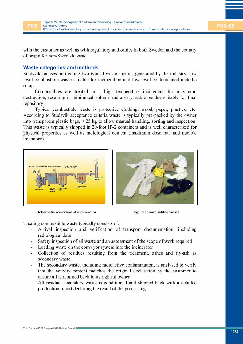
1038
Topic 5: Waste management and decommissioning – Poster presentationsStenmark, AndersEfficient and environmentally sound management of radioactive waste streams from maintenance, upgrade and…
with the customer as well as with regulatory authorities in both Sweden and the country of origin for non-Swedish waste.
Waste categories and methods Studsvik focuses on treating two typical waste streams generated by the industry: low level combustible waste suitable for incineration and low level contaminated metallic scrap.
Combustibles are treated in a high temperature incinerator for maximum destruction, resulting in minimized volume and a very stable residue suitable for final repository.
Typical combustible waste is protective clothing, wood, paper, plastics, etc. According to Studsvik acceptance criteria waste is typically pre-packed by the owner into transparent plastic bags, < 25 kg to allow manual handling, sorting and inspection. This waste is typically shipped in 20-foot IP-2 containers and is well characterized for physical properties as well as radiological content (maximum dose rate and nuclide inventory).
Schematic overview of incinerator Typical combustible waste
Treating combustible waste typically consists of: - Arrival inspection and verification of transport documentation, including
radiological data - Safety inspection of all waste and an assessment of the scope of work required - Loading waste on the conveyor system into the incinerator - Collection of residues resulting from the treatment, ashes and fly-ash as
secondary waste - The secondary waste, including radioactive contamination, is analysed to verify
that the activity content matches the original declaration by the customer to ensure all is returned back to its rightful owner
- All residual secondary waste is conditioned and shipped back with a detailed production report declaring the result of the processing
Third European IRPA Congress 2010, Helsinki, Finland
P05 P05-06

1039
Topic 5: Waste management and decommissioning – Poster presentationsStenmark, AndersEfficient and environmentally sound management of radioactive waste streams from maintenance, upgrade and…
After processing the waste the remaining ash and the fly-ash accumulated in the bag house filters is collected in drums. This secondary waste is conditioned according to customer specifications and is returned to the owner together with a detailed production report.
Environmental aspects is an important part of Studsvik operations and off gas filtering is enhanced by using lime and activated char coal to minimize emissions. To further reduce the environmental impact, Studsvik is recovering energy (~1,5MW) by reusing it within the site to heat facilities.
Metal scrap is comprised of a wide variety of components such as pumps, pipes, duct work and other small waste fitting into a container. Studsvik is also capable of processing large components. This includes heat exchangers and turbine components such as housing and turbine axel, with a typical weight of 150 - 250 tonnes. Large PWR steam generators, weighing 300 tonnes or more, are successfully treated on a regular basis.
Schematic process flow for metal scrap
Typical metal scrap recycled by Studsvik consists of carbon steel, iron alloys, aluminium, lead, copper, brass, etc. Waste is delivered in transport packages such as 20-foot IP-2 containers and large components are transported under alternative arrangements according to international regulations. The acceptance criteria are well defined for physical properties as well as radiological content (maximum dose rate and nuclide inventory).
The treatment of metal waste is shown in the schematic illustration above and can be described as follows: Arrival inspection and verification of transport documentation including
radiological data Safety inspection of all scrap and an assessment of the scope of work required Segmentation as needed to suitable size and weight Surface contamination removed by shot blasting and collected in customer
isolated campaigns Decontaminated scrap metal is melted into ingots and analytically sampled to
verify successful processing
Third European IRPA Congress 2010, Helsinki, Finland
P05 P05-06

1040
Topic 5: Waste management and decommissioning – Poster presentationsStenmark, AndersEfficient and environmentally sound management of radioactive waste streams from maintenance, upgrade and…
To ensure all is returned back to its rightful owner the residual secondary process waste is analysed to verify that the activity content matches the original declaration by customer
All residual secondary waste is conditioned and shipped back with a detailed production report declaring the result of the processing
Metal ingots analytically verified to be in compliance with free release regulation is declared exempt by Studsvik, recycled as valuable raw material and routed back into the metal industry through internationally accepted procedures
Typical scrap metal processed at Studsvik, Sweden (Misc. scraps at left, Turbine at right)
Results Studsvik has in total treated an excess of 10’000 tonnes of combustible material and 20’000 tonnes of metal at its site in Sweden. Today the annual processing rate is approximately 500 tonnes of combustibles and 3500 tonnes of metal with a very high rate of volume reduction, shown below in the two graphs as the average over the historical production. Specific details depend on waste character and may vary.
The resulting secondary waste is prepared according to customer specifications before it is returned. The conditioning typically includes packaging in a 200 litre drums and returning the drum back to the owner where the package undergoes final preparations before storage in a repository in the country of origin. Other forms of packaging may be required on the international market and can be arranged after individual agreement.
0
5 000
10 000
15 000
20 000
Tonnes (acc.)
Incinerables (tonnes) Secondary Waste (~5%b.w.)
Incinerables
0
5 000
10 000
15 000
20 000
Tonnes (acc.)
Metal (tonnes) Secondary Waste (~5%b.w.)
Metal
Third European IRPA Congress 2010, Helsinki, Finland
P05 P05-06

1041
Topic 5: Waste management and decommissioning – Poster presentationsStenmark, AndersEfficient and environmentally sound management of radioactive waste streams from maintenance, upgrade and…
All final packages are analyzed and labelled, the results of which is reported in the final production report. After a completed campaign all secondary waste is returned to customer in country of origin to ensure volume reduced waste (containing the radioactive inventory) is brought back to its rightful owner for final storage.
Gamma-scanning Exempt metal for recycling
Metal samples from each melting batch is analyzed to document data and to allow recycling as exempt metal. Metal ingots meeting exempt levels will be recycled after transfer of ownership from customer to Studsvik.
Transportation Transport of radioactive waste is well regulated at the international level. In order to safely and compliantly transport waste for treatment a variety of regulations must be understood and applied. Studsvik has many years of experience in this field and has a detailed understanding of the regulations for land (ADR - Accord européen relatif au transport international des marchandises Dangereuses par Route), sea (IMO – International Maritime Organization) and air (Dangerous Goods Regulations) transport. Radioactive waste is, however, not transported by air freight due to several reasons, the main one being cost.
To perform a shipment of radioactive waste not only the relevant transport regulation must be complied to fulfil safety concerns but also a special transport authorization must be granted. This authorization must be given according to directive Euratom 2006/117 and approved by the competent authority in both countries. The approval operates on a system of prior notification and approval where-by the applicant (consignee) must apply to the competent authority in the country of export for consent to ship the waste internationally. They in turn seek approval from the competent authority in the country of import (and any countries transited across) prior to approving, or otherwise, the shipment. The Euratom 2006/117 system also enables the competent authorities to place conditions on the shipment such as a requirement to return the secondary waste (ash, dust, slag, etc.) to the country of origin, or to give advance notice of when the consignment will ship.
Third European IRPA Congress 2010, Helsinki, Finland
P05 P05-06

1042
Topic 5: Waste management and decommissioning – Poster presentationsStenmark, AndersEfficient and environmentally sound management of radioactive waste streams from maintenance, upgrade and…
Studsvik regularly performs, in close cooperation with customers, their competent authorities, and Swedish authorities, many international transports from, and back to, countries within EU as well as other international countries. A mandatory condition in all cases is that any individual campaign must in normal cases be concluded within 24 months and all generated secondary waste (any and all waste not possible to classify as exempt and free releasable) must be returned to country of origin.
Conclusions As nuclear power generation experiences a revival many questions on waste treatment must be answered. Prolonged lifetime and worldwide discussions of new power plant constructions highlights the obvious demand of modern, effective and safe waste treatment. Cost for storage at repositories is often volume driven and as such large savings can be obtained by volume reduction before disposal, which enables economically feasible management of waste. The process not only ensures that the volume of waste is significantly reduced but also produces a stable residue suitable for final disposal in a highly cost effective manner. This route offers clear benefits with reduced demand of required space in final repository with prolonged life time at reduced over all cost.
Effective waste treatment is also about a responsible engagement in environmental aspects. Recycling of valuable raw material and energy helps to further reduce the carbon footprint from the energy industry. By using the heat generated during incineration of combustible waste as energy (~1,5MW) to heat on site facilities the carbon foot print is dramatically reduced by replacing fossil fuel energy sources. Metal meeting exempt criteria will be circulated back into the metal industry as a valuable raw material. Reusing high quality metal saves on the environmental impact from our industry and uses limited natural sources efficiently.
Third European IRPA Congress 2010, Helsinki, Finland
P05 P05-06