irrigation - watts watermedia.wattswater.com/pg-f-irrigation.pdf · commitment to safety backflow...
TRANSCRIPT
P r o d u c t G u i d eIrrIgatIon

1
table of ContentsGeneral Information . . . . . . . . . . . . . . . . . . . . . . . . . . . . . . . . . . . . . . . . . . . . . . . . . . . . . . . . . . . . . . . . . . . . . . . . . . . . . . . . . . . . . . . 4 - 7
Series 765 . . . . . . . . . . . . . . 1⁄2” – 2” Pressure Vacuum Breakers . . . . . . . . . . . . . . . . . . . . . . . . . . . . . . . . . . . . . . . . . . . . . . . . . . . . . . . 8
Series 767FR . . . . . . . . . . . . 3⁄4” – 2” Freeze Resistant Pressure Vacuum Breakers . . . . . . . . . . . . . . . . . . . . . . . . . . . . . . . . . . . . . . . . 9
Series 850 . . . . . . . . . . . . . . 1⁄2” – 2” Double Check Valve Assemblies . . . . . . . . . . . . . . . . . . . . . . . . . . . . . . . . . . . . . . . . . . . . . . . . . 10
Series 850U . . . . . . . . . . . . 1⁄2” – 2” Double Check Valve Assemblies w/Union End Ball Valves . . . . . . . . . . . . . . . . . . . . . . . . . . . . . 11
MasterSeries® 850 . . . . . . . 21⁄2” – 10” Double Check Valve Assemblies . . . . . . . . . . . . . . . . . . . . . . . . . . . . . . . . . . . . . . . . . . . . . . . 12
Series 870V . . . . . . . . . . . . . 21⁄2” – 10” Double Check Valve Assemblies “N” & “V” Pattern . . . . . . . . . . . . . . . . . . . . . . . . . . . . . . . 13
Series 825Y . . . . . . . . . . . . . 3⁄4” – 2” Reduced Pressure Zone Assemblies . . . . . . . . . . . . . . . . . . . . . . . . . . . . . . . . . . . . . . . . . . . . . . 14
Series 825YA . . . . . . . . . . . 3⁄4” – 2” Reduced Pressure Zone Assemblies “N” & Inline Pattern . . . . . . . . . . . . . . . . . . . . . . . . . . . . . 15
Series 860 . . . . . . . . . . . . . . 1⁄2” – 2” Reduced Pressure Zone Assemblies . . . . . . . . . . . . . . . . . . . . . . . . . . . . . . . . . . . . . . . . . . . . . . 16
Series 860U . . . . . . . . . . . . 1⁄2” – 2” Reduced Pressure Zone Assemblies w/Union End Ball Valves . . . . . . . . . . . . . . . . . . . . . . . . . . 17
MasterSeries® 860 . . . . . . . 21⁄2” – 10” Reduced Pressure Zone Assemblies . . . . . . . . . . . . . . . . . . . . . . . . . . . . . . . . . . . . . . . . . . . . 18
MasterSeries® 880V . . . . . . 21⁄2” – 10” Reduced Pressure Zone Assemblies “N” & “V” Pattern . . . . . . . . . . . . . . . . . . . . . . . . . . . . 19
Series 710/715 . . . . . . . . . . 1⁄2” – 2” Atmospheric Vacuum Breakers . . . . . . . . . . . . . . . . . . . . . . . . . . . . . . . . . . . . . . . . . . . . . . . . . . 20
Series 510 . . . . . . . . . . . . . . 1⁄2” – 1” Dual Check Backflow Preventers . . . . . . . . . . . . . . . . . . . . . . . . . . . . . . . . . . . . . . . . . . . . . . . . . 21
Series 731 . . . . . . . . . . . . . . 3⁄4” Hose Connection Vacuum Breakers . . . . . . . . . . . . . . . . . . . . . . . . . . . . . . . . . . . . . . . . . . . . . . . . . . . 22
Series FPHB-1 . . . . . . . . . . . 3⁄4” – 1” Key Operated Wall Hydrants . . . . . . . . . . . . . . . . . . . . . . . . . . . . . . . . . . . . . . . . . . . . . . . . . . . . . 23
Series 601-P, 601-M . . . . . . 1⁄2” – 2” Air Gap Drains for Use With MasterSeries‚ 860/860U . . . . . . . . . . . . . . . . . . . . . . . . . . . . . . . . 24
Series AGD . . . . . . . . . . . . . 3⁄4” – 2” and 21⁄2” – 10” Air Gap Drains for Use w/Reduced Pressure Devices . . . . . . . . . . . . . . . . . . . . 25
Series 650A . . . . . . . . . . . . . 1⁄2” – 2” Wye Strainers . . . . . . . . . . . . . . . . . . . . . . . . . . . . . . . . . . . . . . . . . . . . . . . . . . . . . . . . . . . . . . . . 26
Series 758A . . . . . . . . . . . . . 21⁄2” – 10” Wye Strainers . . . . . . . . . . . . . . . . . . . . . . . . . . . . . . . . . . . . . . . . . . . . . . . . . . . . . . . . . . . . . . 27
Series 611 . . . . . . . . . . . . . . 3” – 10” Valve Setter Used w/MasterSeries . . . . . . . . . . . . . . . . . . . . . . . . . . . . . . . . . . . . . . . . . . . . . . . 28
Series FPTC-1 . . . . . . . . . . . 1⁄8” – 3⁄4” Thermostatic Freeze Relief . . . . . . . . . . . . . . . . . . . . . . . . . . . . . . . . . . . . . . . . . . . . . . . . . . . . . 29
TK-1 . . . . . . . . . . . . . . . . . . . Backflow Preventer Test Kit . . . . . . . . . . . . . . . . . . . . . . . . . . . . . . . . . . . . . . . . . . . . . . . . . . . . . . . . . . . . 30
Series TC-1 . . . . . . . . . . . . . Bronze, Full Port Test Cock . . . . . . . . . . . . . . . . . . . . . . . . . . . . . . . . . . . . . . . . . . . . . . . . . . . . . . . . . . . . . 31
Spool Adapter . . . . . . . . . . . 4” – 8” DuraCheck to MasterSeries‚ Spacer Spool Adapter Kit . . . . . . . . . . . . . . . . . . . . . . . . . . . . . . . . 32
Series 622 . . . . . . . . . . . . . . 1⁄2” – 2” Bronze, Full Port Ball Valves . . . . . . . . . . . . . . . . . . . . . . . . . . . . . . . . . . . . . . . . . . . . . . . . . . . . . 33
Series 623-BS . . . . . . . . . . . 1⁄4” – 3” 2-Piece, Full Port, Brass Ball Valves . . . . . . . . . . . . . . . . . . . . . . . . . . . . . . . . . . . . . . . . . . . . . . . 34
Series 624-BS . . . . . . . . . . . 3⁄8” – 3” Brass Cross-Handle Gate Valves . . . . . . . . . . . . . . . . . . . . . . . . . . . . . . . . . . . . . . . . . . . . . . . . . . 35
Series PRV-1 . . . . . . . . . . . . 1⁄2” – 1” Water Pressure Reducing Valves . . . . . . . . . . . . . . . . . . . . . . . . . . . . . . . . . . . . . . . . . . . . . . . . . 36
Series PRV-1-L . . . . . . . . . . 11⁄4” – 2” Water Pressure Reducing Valves . . . . . . . . . . . . . . . . . . . . . . . . . . . . . . . . . . . . . . . . . . . . . . . . 37
Series PRV-2 . . . . . . . . . . . . 1⁄2” – 1” Water Pressure Reducing Valves . . . . . . . . . . . . . . . . . . . . . . . . . . . . . . . . . . . . . . . . . . . . . . . . . 38
Series PRV-2-L . . . . . . . . . . 11⁄4” – 2” Water Pressure Reducing Valves . . . . . . . . . . . . . . . . . . . . . . . . . . . . . . . . . . . . . . . . . . . . . . . . 39
Series SA-1 . . . . . . . . . . . . . 3⁄8” – 1⁄2” Mini Water Hammer Arrestors . . . . . . . . . . . . . . . . . . . . . . . . . . . . . . . . . . . . . . . . . . . . . . . . . . 40
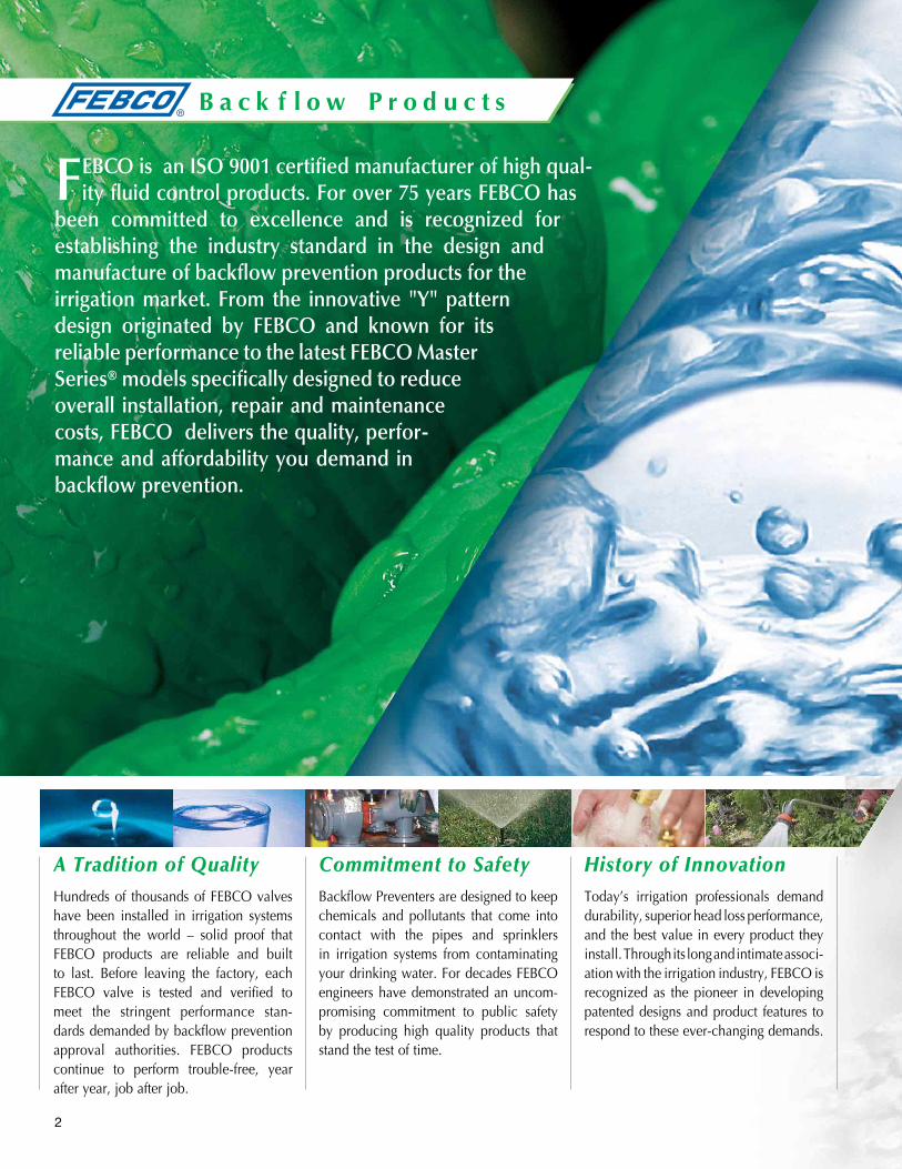
Commitment to SafetyBackflow Preventers are designed to keep chemicals and pollutants that come into contact with the pipes and sprinklers in irrigation systems from contaminating your drinking water. For decades FEBCO engineers have demonstrated an uncom-promising commitment to public safety by producing high quality products that stand the test of time.
History of InnovationToday’s irrigation professionals demand durability, superior head loss performance, and the best value in every product they install. Through its long and intimate associ-ation with the irrigation industry, FEBCO is recognized as the pioneer in developing patented designs and product features to respond to these ever-changing demands.
A Tradition of QualityHundreds of thousands of FEBCO valves have been installed in irrigation systems throughout the world – solid proof that FEBCO products are reliable and built to last. Before leaving the factory, each FEBCO valve is tested and verified to meet the stringent performance stan-dards demanded by backflow prevention approval authorities. FEBCO products continue to perform trouble-free, year after year, job after job.
B a c k f l o w P r o d u c t s
FEBCO is an ISO 9001 certified manufacturer of high qual-ity fluid control products. For over 75 years FEBCO has
been committed to excellence and is recognized for establishing the industry standard in the design and manufacture of backflow prevention products for the irrigation market. From the innovative "Y" pattern design originated by FEBCO and known for its reliable performance to the latest FEBCO Master Series® models specifically designed to reduce overall installation, repair and maintenance costs, FEBCO delivers the quality, perfor-mance and affordability you demand in backflow prevention.
2

Model 765 Pressure Vacuum Breaker 1⁄2" to 2"
•Simpletoservice
•Freezeresistantdesign
•Unionendoption
Models 850 & 860 Double Check & reduced Pressure assemblies 1⁄2" to 2"
•In-linedesign
•Topentryforeasyaccess
•Unionendoptionavailable
Models 870V & 880V Double Check & reduced Pressure assemblies 21⁄2" to 10"
•Compactandpatented"N-Shape"design
•Valvesetterinstallationoption
•Savestimeandmoney
•Traditionalin-linemodelsalsoavailable(Models850&860)
Models 825Y & 825Ya reduced Pressure assembly 3⁄4" to 2"
•Traditional"Y"pattern
•Compact"YA"designoption
•Replaceableseats
A Full Range of ProductsFEBCO offers a variety of backflow pre-vention products for irrigation systems large and small; all built with the same attention to quality and performance that FEBCO customers have come to expect.
3

4
• One PVB required to protect the whole system; on/off valves can be located downstream of the PVB.
• PVB’s must be installed a minimum of 12" above the highest point of water in the system.
• PVB’s must be tested by a State-certified Backflow Assembly Tester* annually or when moved/repaired.
• No chemical or fertilizer can be introduced into an irrigation system protected with PVB’s
• No pumps or source of backpressure on downstream side or after a PVB.
• Anti-siphon, multi-zone.• Can be pressurized a full 24 hours.• Freeze resistant with “FR” feature.
general Information
FEBCO has developed an extensive line of products for the irrigation market . Some of our innovations in this area include our patented freeze protected pressure vacuum breaker, patented 825YA backflow assembly hose connection vacuum breaker, as well as our through the wall irrigation shutoff valve . This product guide showcases our full line of products for irrigation applications .
Backflow Installation and Freeze Protection Guidelines
AVB . . . Atmospheric Vacuum BreakerFEBCO Series 710, 715
• One AVB required for each irrigation zone; no on/off valves allowed downstream of the AVB.
• Each AVB must be installed a minimum of 6" above the high-est point of water in the zone it protects.
• No chemical or fertilizer can be introduced into an irrigation system protected with AVB’s.
• No pumps or sources for backpressure on downstream side of an AVB.
• Anti-siphon, single zone.• Can be only pressurized a maximum of a 12 hour period out
of 24 hours.
PVB . . . Pressure Vacuum BreakerFEBCO Series 765, 767FR
710, 715
765, 767FR
5
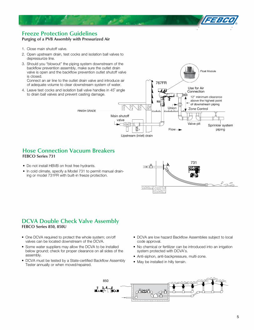
1. Close main shutoff valve.2. Open upstream drain, test cocks and isolation ball valves to
depressurize line.3. Should you “blowout” the piping system downstream of the
backflow prevention assembly, make sure the outlet drain valve is open and the backflow prevention outlet shutoff valve is closed. Connect an air line to the outlet drain valve and introduce air of adequate volume to clear downstream system of water.
4. Leave test cocks and isolation ball valve handles in 45˚ angle to drain ball valves and prevent casting damage.
Freeze Protection GuidelinesPurging of a PVB Assembly with Pressurized Air
Hose Connection Vacuum BreakersFEBCO Series 731
• Do not install HBVB on frost free hydrants.• In cold climate, specify a Model 731 to permit manual drain-
ing or model 731FR with built-in freeze protection.
• One DCVA required to protect the whole system; on/off valves can be located downstream of the DCVA.
• Some water suppliers may allow the DCVA to be installed below ground; check for proper clearance on all sides of the assembly.
• DCVA must be tested by a State-certified Backflow Assembly Tester annually or when moved/repaired.
• DCVA are low hazard Backflow Assemblies subject to local code approval.
• No chemical or fertilizer can be introduced into an irrigation system protected with DCVA’s.
• Anti-siphon, anti-backpressure, multi-zone.• May be installed in hilly terrain.
DCVA Double Check Valve AssemblyFEBCO Series 850, 850U
850
767FR
731
Use for Air Connection

6
RPZ . . . Reduced Pressure Zone AssemblyFEBCO Series 825Y, 825YA, 860
• One RPZ required to serve the whole system;on/off valves can be located downstream of the RPZ.
• RPZ’s must be installed a minimum of 12" above ground level.
• RPZ’s must be tested by a State-certified Backflow Assembly Tester annually or when moved/repaired.
• In an RPZ equipped system, fertilizer and other agricultural chemicals may be introduced downstream or after the RPZ.
• Anti-siphon, anti-backpressure, multi-zone.• May be installed in hilly terrain.
Freeze Protection GuidelinesPurging of a DCVA Assembly with Pressurized Air
1 . Close main shutoff valve .
2 . With shutoff No . 1 and No . 2 open, depressurize line .
3 . Open all Test Cocks .
4 . Downstream line can be purged with pressurized air through Test Cock No . 4 .
5 . To purge upstream line, close No . 1 shutoff valve . Purging with air can now be done between Test Cock 1 and inlet drain .
6 . When air purging is complete, open No . 1 shutoff to drain rest of DCVA device .
7 . Leave Test Cocks open, turn shutoff handles to a 45˚ position .
Series FPHB-1 has been designed to provide a convenient means of shutting off the water supply when servicing or winterizing an irrigation system . When using the FPHB-1 the irrigation controller should be located in the garage or other accessible location to aid in system servicing .
Purging of a DCVA Assembly with Pressurized air using the FPHB-1 Hydrant
To Purge the system using the drain or blow down port of the FPHB-1 Hydrant1 . Using the hydrant “key”, close the FPHB-1 completely .
2 . Turn hydrant “key” counter clockwise 2 full turns from the closed position .
3 . Connect the air supply to hydrant drain connection and purge the system .
4 . Leave test cocks and isolation ball valve handles at 45˚ angle to prevent freezing .
860
Freeze Protection Guidelines Using FEBCO FPHB-1
FEBCO FPHB-1
850

7
Purging of an RPZ Assembly with Pressurized Air using the FPHB-1
To purge the system using a drain valve downstream of the RPZ/FPHB-1.1 . Using the hydrant “key”, close the FPHB-1 Hydrant com-
pletely .
2 . Open the FPHB-1 drain port and Backflow preventer test cocks (relief valve will vent) .
3 . Connect the air supply to the outlet drain valve (A) and close the outlet ball valve (B) .
4 . After the system has been purged, leave all test cocks and isolation ball valve handles in a 45˚ position .
To purge the system using the drain or blow down port of the FPHB-1 Hydrant1 . Using the hydrant “key”, close the FPHB-1 hydrant com-
pletely .
2 . Turn hydrant “key” counter clockwise 2 full turns from the closed position .
3 . Connect the air supply to hydrant drain connection and purge the system .
4 . Leave test cocks and isolation ball valve handles at 45˚ angle to prevent freezing .
Freeze Protection GuidelinesPurging of a RPZ Assembly with Pressurized Air
1. Close main shutoff valve.2. With shutoff No. 1 and No. 2 open, depressurize line.3. Open all Test Cocks (relief valve will vent).4. If you “blowout” the piping downstream of the backflow
assembly using compressed air, connect the air supply to the outlet drain and close the outlet ball valve.
5. To purge upstream line, close No. 1 shutoff valve. Purging with air can now be done between Test Cock 1 and inlet drain.
6. When air purging is complete, open No. 1 shutoff to drain rest of RPZ device.
7. Leave Test Cocks open, turn shutoff handles to a 45˚ position.
Series FPHB-1 has been designed to provide a convenient means of shutting off the water supply when servicing or winterizing an irrigation system . When using the FPHB-1 the irrigation controller should be located in the garage or other accessible location to aid in system servicing .
860
825YA
Freeze Protection Guidelines Using FEBCO FPHB-1
FHB-1

8
The FEBCO Series 765 Pressure Vacuum Breakers are used to protect against health hazard and non-health hazard backsiphonage conditions in industrial plants, cooling tow-ers laboratories, laundries, swimming pools and lawn sprinkler systems .
Series 765Pressure Vacuum BreakersSize: 1⁄2" – 2" (15 – 50mm)
765 765U
Features• Allbronzebodyfordurability.Onecheckvalveandanair
opening port in one assembly
• Lightweightpoppetsealsairopeningunderminimumflowconditions
• Simpleserviceprocedures.Allinternalpartsserviceableinline from the top of the unit
• Designedforminimumheadloss
• Engineeredplasticbonnetprotectvalvebodiesfromfreezedamage
• Optionalunionendballvalvesforeasyremovalandulti-mate freeze protection
• EndConnections-NPTANSI/ASMEB1.20.1
MaterialsMain Valve Body: Bronze
Elastomers: Nitrile
Pressure – TemperatureMax . Working Pressure: 150psi (10 .3 bar)
Hydrostatic Test Press: 300psi (20 .7 bar)
Temperature Range: 32°F to 140°F (0°C to 60°C)
Models• UnionEndBallValves
• BronzeBonnet,11⁄2" & 2" (40 & 50mm)
Approvals – Standards• ApprovedbytheFoundationforCross-ConnectionControl
and Hydraulic Research at the University of Southern California .
1020 B64.1.2
9
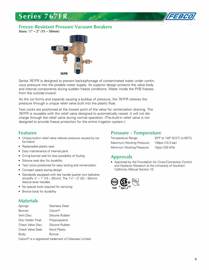
Series 767FR is designed to prevent backsiphonage of contaminated water under contin-uous pressure into the potable water supply . Its superior design protects the valve body and internal components during sudden freeze conditions . Water inside the PVB freezes from the outside-inward .
As the ice forms and expands causing a buildup of pressure, the 767FR relieves the pressure through a unique relief valve built into the plastic float .
Test cocks are positioned at the lowest point of the valve for winterization draining . The 767FR is reusable with the relief valve designed to automatically reseat . It will not dis-charge through the relief valve during normal operation . (The built-in relief valve is not designed to provide freeze protection for the entire irrigation system .)
Series 767FrFreeze-Resistant Pressure Vacuum BreakersSizes: 1⁄2" – 2" (15 – 50mm)
767FR
Features• Uniquebuilt-inreliefvalverelievespressurecausedbyice
formation
• Replaceableplasticseat
• Easymaintenanceofinternalparts
• O-ringbonnetsealforlesspossibilityoffouling
• Siliconeseatdiscfordurability
• Testcockspositionedforeasytestingandwinterization
• Compactspacesavingdesign
• Standardlyequippedwithteehandlequarterturnballvalveshutoffs 1⁄2" – 1" (15 – 25mm) . The 11⁄4" – 2" (32 – 50mm) feature lever handles
• Nospecialtoolsrequiredforservicing
• Bronzebodyfordurability
MaterialsSprings: Stainless Steel
Bonnet: Celcon®
Vent Disc: Silicone Rubber
Disc Holder Float: Polypropylene
Check Valve Disc: Silicone Rubber
Check Valve Seat: Noryl Plastic
Body: Bronze
Celcon® is a registered trademark of Celanese Limited .
Pressure - TemperatureTemperature Range: 33°F to 140° (0 .5°C to 60°C)
Maximum Working Pressure: 150psi (10 .3 bar)
Minimum Working Pressure: 15psi (103 kPa)
Approvals• ApprovedbytheFoundationforCross-ConnectionControl
and Hydraulic Research at the University of Southern California, Manual Section 10 .
1020 B64.1.2
10
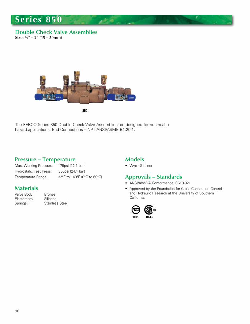
The FEBCO Series 850 Double Check Valve Assemblies are designed for non-health hazard applications . End Connections – NPT ANSI/ASME B1 .20 .1 .
Series 850Double Check Valve AssembliesSize: 1⁄2" – 2" (15 – 50mm)
850
Pressure – Temperature Max . Working Pressure: 175psi (12 .1 bar)
Hydrostatic Test Press: 350psi (24 .1 bar)
Temperature Range: 32°F to 140°F (0°C to 60°C)
MaterialsValve Body: Bronze Elastomers: Silicone Springs: Stainless Steel
Models• Wye-Strainer
Approvals – Standards• ANSI/AWWAConformance(C510-92)
• ApprovedbytheFoundationforCross-ConnectionControland Hydraulic Research at the University of Southern California .
1015 B64.5
11
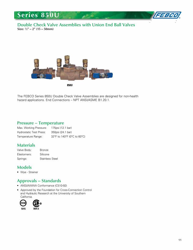
The FEBCO Series 850U Double Check Valve Assemblies are designed for non-health hazard applications . End Connections – NPT ANSI/ASME B1 .20 .1 .
Series 850UDouble Check Valve Assemblies with Union End Ball ValvesSize: 1⁄2" – 2" (15 – 50mm)
850U
Pressure – TemperatureMax . Working Pressure: 175psi (12 .1 bar)
Hydrostatic Test Press: 350psi (24 .1 bar)
Temperature Range: 32°F to 140°F (0°C to 60°C)
MaterialsValve Body: Bronze
Elastomers: Silicone
Springs: Stainless Steel
Models• Wye-Strainer
Approvals – Standards• ANSI/AWWAConformance(C510-92)
• ApprovedbytheFoundationforCross-ConnectionControland Hydraulic Research at the University of Southern California .
1015 B64.5
12
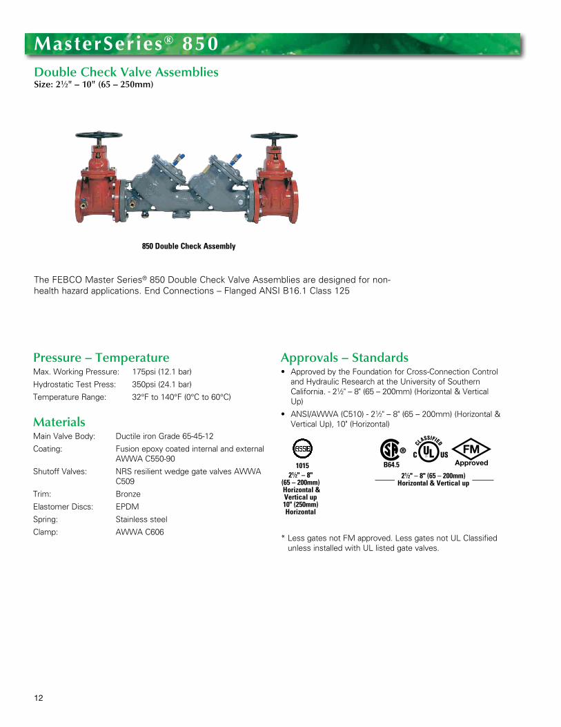
The FEBCO Master Series® 850 Double Check Valve Assemblies are designed for non-health hazard applications . End Connections – Flanged ANSI B16 .1 Class 125
MasterSeries® 850Double Check Valve AssembliesSize: 21⁄2" – 10" (65 – 250mm)
Pressure – TemperatureMax . Working Pressure: 175psi (12 .1 bar)
Hydrostatic Test Press: 350psi (24 .1 bar)
Temperature Range: 32°F to 140°F (0°C to 60°C)
MaterialsMain Valve Body: Ductile iron Grade 65-45-12
Coating: Fusion epoxy coated internal and external AWWA C550-90
Shutoff Valves: NRS resilient wedge gate valves AWWA C509
Trim: Bronze
Elastomer Discs: EPDM
Spring: Stainless steel
Clamp: AWWA C606
Approvals – Standards• ApprovedbytheFoundationforCross-ConnectionControl
and Hydraulic Research at the University of Southern California . - 21⁄2" – 8" (65 – 200mm) (Horizontal & Vertical Up)
• ANSI/AWWA(C510)-21⁄2 " – 8" (65 – 200mm) (Horizontal & Vertical Up), 10" (Horizontal)
* Less gates not FM approved . Less gates not UL Classified unless installed with UL listed gate valves .
1015 B64.521⁄2" – 8"
(65 – 200mm) Horizontal & Vertical up 10" (250mm) Horizontal
21⁄2" – 8" (65 – 200mm) Horizontal & Vertical up
850 Double Check Assembly
13
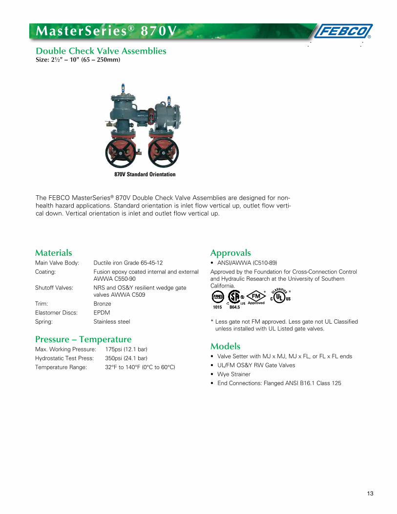
The FEBCO MasterSeries® 870V Double Check Valve Assemblies are designed for non-health hazard applications . Standard orientation is inlet flow vertical up, outlet flow verti-cal down . Vertical orientation is inlet and outlet flow vertical up .
MasterSeries® 870VDouble Check Valve AssembliesSize: 21⁄2" – 10" (65 – 250mm)
870V Standard Orientation
MaterialsMain Valve Body: Ductile iron Grade 65-45-12
Coating: Fusion epoxy coated internal and external AWWA C550-90
Shutoff Valves: NRS and OS&Y resilient wedge gate valves AWWA C509
Trim: Bronze
Elastomer Discs: EPDM
Spring: Stainless steel
Pressure – TemperatureMax . Working Pressure: 175psi (12 .1 bar)
Hydrostatic Test Press: 350psi (24 .1 bar)
Temperature Range: 32°F to 140°F (0°C to 60°C)
Approvals• ANSI/AWWA(C510-89)
Approved by the Foundation for Cross-Connection Control and Hydraulic Research at the University of Southern California .
* Less gate not FM approved . Less gate not UL Classified unless installed with UL Listed gate valves .
Models• ValveSetterwithMJxMJ,MJxFL,orFLxFLends
• UL/FMOS&YRWGateValves
•WyeStrainer
• EndConnections:FlangedANSIB16.1Class125
1015 B64.5
* *
14
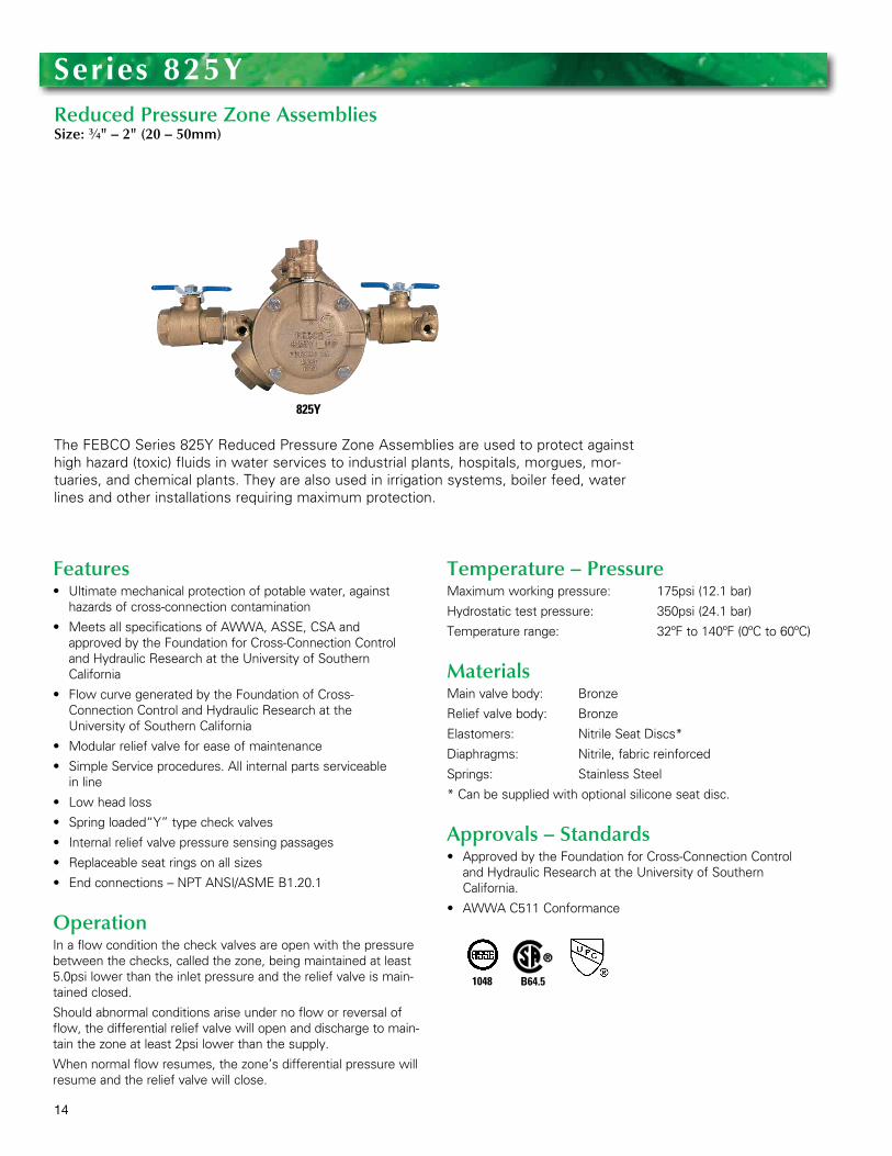
The FEBCO Series 825Y Reduced Pressure Zone Assemblies are used to protect against high hazard (toxic) fluids in water services to industrial plants, hospitals, morgues, mor-tuaries, and chemical plants . They are also used in irrigation systems, boiler feed, water lines and other installations requiring maximum protection .
Series 825YReduced Pressure Zone AssembliesSize: 3⁄4" – 2" (20 – 50mm)
825Y
Features• Ultimatemechanicalprotectionofpotablewater,against
hazards of cross-connection contamination
• MeetsallspecificationsofAWWA,ASSE,CSAandapproved by the Foundation for Cross-Connection Control and Hydraulic Research at the University of Southern California
• FlowcurvegeneratedbytheFoundationofCross-Connection Control and Hydraulic Research at the University of Southern California
• Modularreliefvalveforeaseofmaintenance
• SimpleServiceprocedures.Allinternalpartsserviceable in line
• Lowheadloss
• Springloaded“Y”typecheckvalves
• Internalreliefvalvepressuresensingpassages
• Replaceableseatringsonallsizes
• Endconnections–NPTANSI/ASMEB1.20.1
OperationIn a flow condition the check valves are open with the pressure between the checks, called the zone, being maintained at least 5 .0psi lower than the inlet pressure and the relief valve is main-tained closed .
Should abnormal conditions arise under no flow or reversal of flow, the differential relief valve will open and discharge to main-tain the zone at least 2psi lower than the supply .
When normal flow resumes, the zone’s differential pressure will resume and the relief valve will close .
Temperature – PressureMaximum working pressure: 175psi (12 .1 bar)
Hydrostatic test pressure: 350psi (24 .1 bar)
Temperature range: 32ºF to 140ºF (0ºC to 60ºC)
MaterialsMain valve body: Bronze
Relief valve body: Bronze
Elastomers: Nitrile Seat Discs*
Diaphragms: Nitrile, fabric reinforced
Springs: Stainless Steel
* Can be supplied with optional silicone seat disc .
Approvals – Standards• ApprovedbytheFoundationforCross-ConnectionControl
and Hydraulic Research at the University of Southern California .
• AWWAC511Conformance
1048 B64.5
15
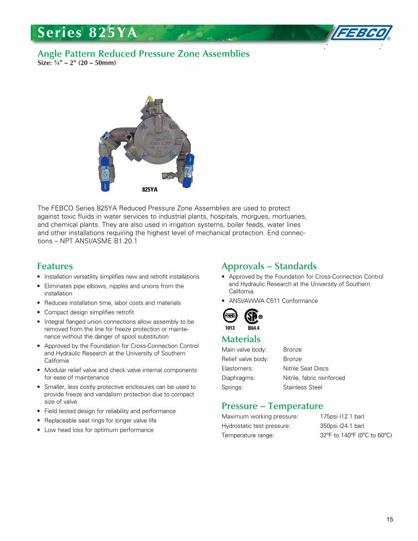
The FEBCO Series 825YA Reduced Pressure Zone Assemblies are used to protect against toxic fluids in water services to industrial plants, hospitals, morgues, mortuaries, and chemical plants . They are also used in irrigation systems, boiler feeds, water lines and other installations requiring the highest level of mechanical protection . End connec-tions – NPT ANSI/ASME B1 .20 .1
Series 825YaAngle Pattern Reduced Pressure Zone AssembliesSize: 3⁄4" – 2" (20 – 50mm)
825YA
Features• Installationversatilitysimplifiesnewandretrofitinstallations
• Eliminatespipeelbows,nipplesandunionsfromthe installation
• Reducesinstallationtime,laborcostsandmaterials
• Compactdesignsimplifiesretrofit
• Integralflangedunionconnectionsallowassemblytoberemoved from the line for freeze protection or mainte-nance without the danger of spool substitution
• ApprovedbytheFoundationforCross-ConnectionControland Hydraulic Research at the University of Southern California
• Modularreliefvalveandcheckvalveinternalcomponentsfor ease of maintenance
• Smaller,lesscostlyprotectiveenclosurescanbeusedtoprovide freeze and vandalism protection due to compact size of valve
• Fieldtesteddesignforreliabilityandperformance
• Replaceableseatringsforlongervalvelife
• Lowheadlossforoptimumperformance
Approvals – Standards• ApprovedbytheFoundationforCross-ConnectionControl
and Hydraulic Research at the University of Southern California .
• ANSI/AWWAC511Conformance
MaterialsMain valve body: Bronze
Relief valve body: Bronze
Elastomers: Nitrile Seat Discs
Diaphragms: Nitrile, fabric reinforced
Springs: Stainless Steel
Pressure – TemperatureMaximum working pressure: 175psi (12 .1 bar)
Hydrostatic test pressure: 350psi (24 .1 bar)
Temperature range: 32ºF to 140ºF (0ºC to 60ºC)
1013 B64.4
16
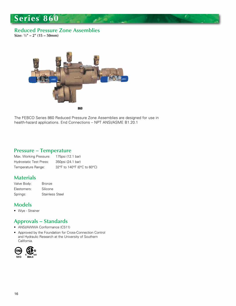
The FEBCO Series 860 Reduced Pressure Zone Assemblies are designed for use in health-hazard applications . End Connections – NPT ANSI/ASME B1 .20 .1
Series 860Reduced Pressure Zone AssembliesSize: 1⁄2" – 2" (15 – 50mm)
860
Pressure – TemperatureMax . Working Pressure: 175psi (12 .1 bar)
Hydrostatic Test Press: 350psi (24 .1 bar)
Temperature Range: 32°F to 140°F (0°C to 60°C)
MaterialsValve Body: Bronze
Elastomers: Silicone
Springs: Stainless Steel
Models• Wye-Strainer
Approvals – Standards• ANSI/AWWAConformance(C511)
• ApprovedbytheFoundationforCross-ConnectionControland Hydraulic Research at the University of Southern California .
1013 B64.4
17
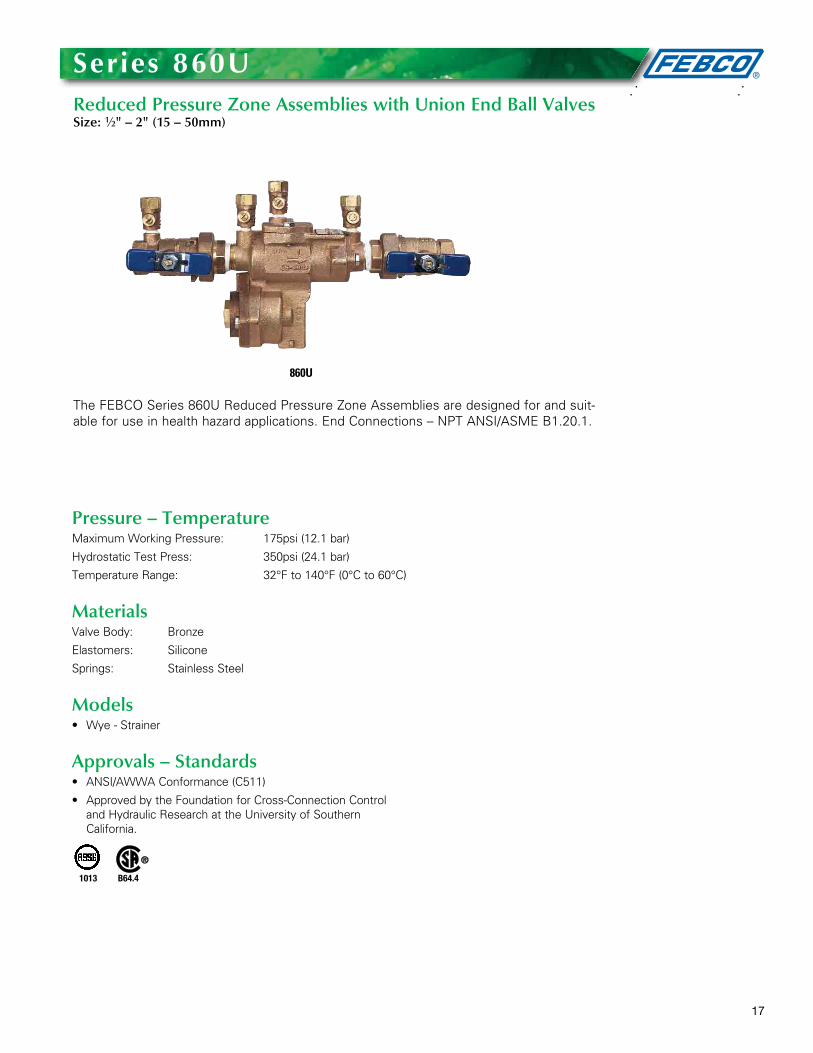
The FEBCO Series 860U Reduced Pressure Zone Assemblies are designed for and suit-able for use in health hazard applications . End Connections – NPT ANSI/ASME B1 .20 .1 .
Series 860UReduced Pressure Zone Assemblies with Union End Ball ValvesSize: 1⁄2" – 2" (15 – 50mm)
860U
Pressure – TemperatureMaximum Working Pressure: 175psi (12 .1 bar)
Hydrostatic Test Press: 350psi (24 .1 bar)
Temperature Range: 32°F to 140°F (0°C to 60°C)
MaterialsValve Body: Bronze
Elastomers: Silicone
Springs: Stainless Steel
Models• Wye-Strainer
Approvals – Standards• ANSI/AWWAConformance(C511)
• ApprovedbytheFoundationforCross-ConnectionControland Hydraulic Research at the University of Southern California .
1013 B64.4
18
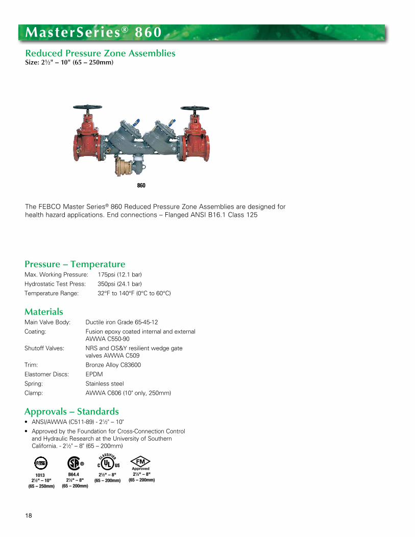
The FEBCO Master Series® 860 Reduced Pressure Zone Assemblies are designed for health hazard applications . End connections – Flanged ANSI B16 .1 Class 125
MasterSeries® 860Reduced Pressure Zone AssembliesSize: 21⁄2" – 10" (65 – 250mm)
860
Pressure – TemperatureMax . Working Pressure: 175psi (12 .1 bar)
Hydrostatic Test Press: 350psi (24 .1 bar)
Temperature Range: 32°F to 140°F (0°C to 60°C)
MaterialsMain Valve Body: Ductile iron Grade 65-45-12
Coating: Fusion epoxy coated internal and external AWWA C550-90
Shutoff Valves: NRS and OS&Y resilient wedge gate valves AWWA C509
Trim: Bronze Alloy C83600
Elastomer Discs: EPDM
Spring: Stainless steel
Clamp: AWWA C606 (10" only, 250mm)
Approvals – Standards• ANSI/AWWA(C511-89)-21⁄2" – 10"
• ApprovedbytheFoundationforCross-ConnectionControland Hydraulic Research at the University of Southern California . - 21⁄2" – 8" (65 – 200mm)
1013 B64.4 21⁄2" – 8"(65 – 200mm)21⁄2" – 8"
(65 – 200mm)21⁄2" – 10"
(65 – 250mm)
21⁄2" – 8"(65 – 200mm)
19
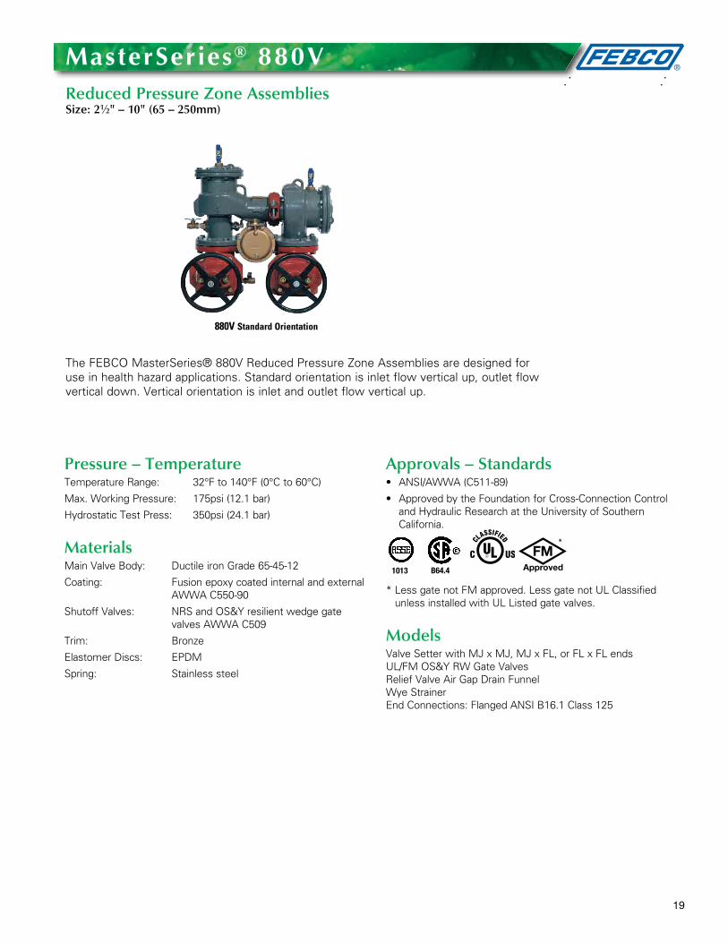
The FEBCO MasterSeries® 880V Reduced Pressure Zone Assemblies are designed for use in health hazard applications . Standard orientation is inlet flow vertical up, outlet flow vertical down . Vertical orientation is inlet and outlet flow vertical up .
MasterSeries® 880VReduced Pressure Zone AssembliesSize: 21⁄2" – 10" (65 – 250mm)
Pressure – TemperatureTemperature Range: 32°F to 140°F (0°C to 60°C)
Max . Working Pressure: 175psi (12 .1 bar)
Hydrostatic Test Press: 350psi (24 .1 bar)
MaterialsMain Valve Body: Ductile iron Grade 65-45-12
Coating: Fusion epoxy coated internal and external AWWA C550-90
Shutoff Valves: NRS and OS&Y resilient wedge gate valves AWWA C509
Trim: Bronze
Elastomer Discs: EPDM
Spring: Stainless steel
Approvals – Standards• ANSI/AWWA(C511-89)
• ApprovedbytheFoundationforCross-ConnectionControland Hydraulic Research at the University of Southern California .
* Less gate not FM approved . Less gate not UL Classified unless installed with UL Listed gate valves .
ModelsValveSetterwithMJxMJ,MJxFL,orFLxFLends UL/FM OS&Y RW Gate Valves Relief Valve Air Gap Drain Funnel Wye Strainer End Connections: Flanged ANSI B16 .1 Class 125
1013 B64.4
880V Standard Orientation
*
20
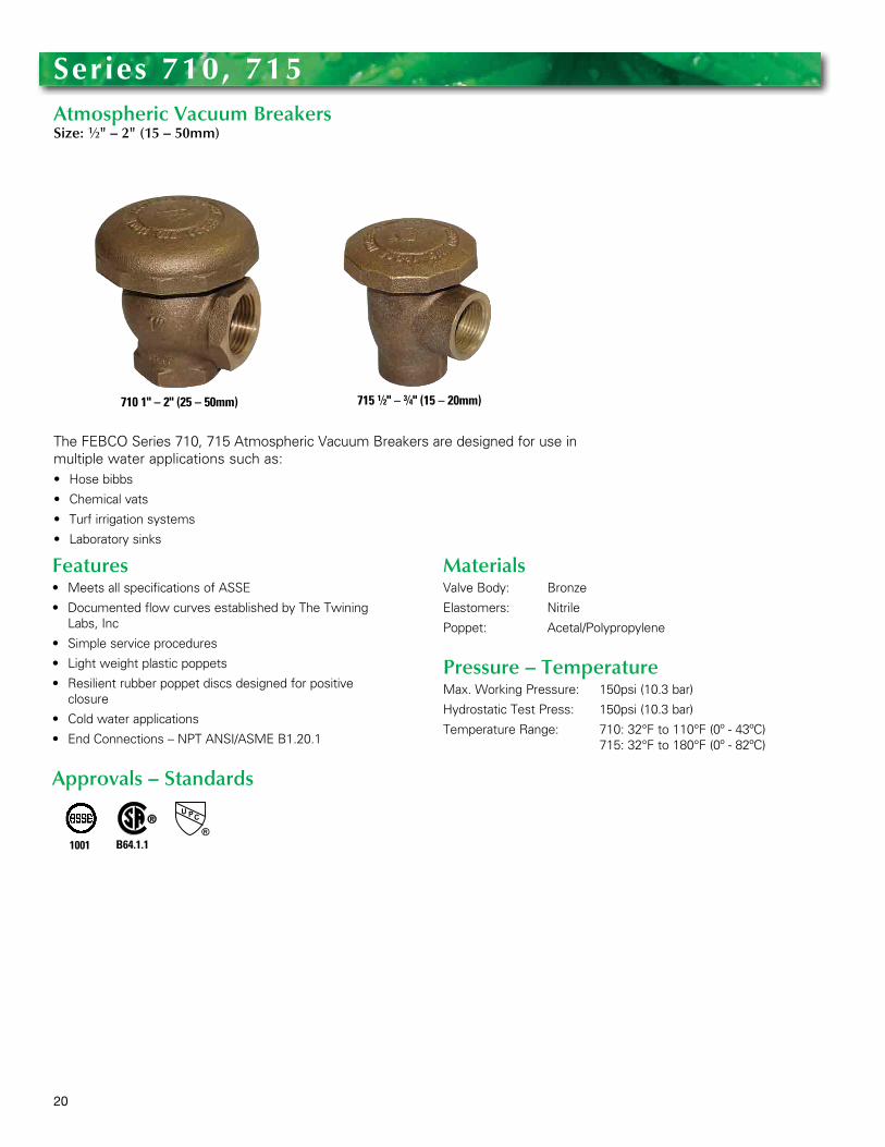
The FEBCO Series 710, 715 Atmospheric Vacuum Breakers are designed for use in multiple water applications such as:• Hosebibbs
• Chemicalvats
• Turfirrigationsystems
• Laboratorysinks
Series 710, 715Atmospheric Vacuum BreakersSize: 1⁄2" – 2" (15 – 50mm)
710 1" – 2" (25 – 50mm)
Features• MeetsallspecificationsofASSE
• DocumentedflowcurvesestablishedbyTheTwiningLabs, Inc
• Simpleserviceprocedures
• Lightweightplasticpoppets
• Resilientrubberpoppetdiscsdesignedforpositive closure
• Coldwaterapplications
• EndConnections–NPTANSI/ASMEB1.20.1
Approvals – Standards
MaterialsValve Body: Bronze
Elastomers: Nitrile
Poppet: Acetal/Polypropylene
Pressure – TemperatureMax . Working Pressure: 150psi (10 .3 bar)
Hydrostatic Test Press: 150psi (10 .3 bar)
Temperature Range: 710: 32°F to 110°F (0º - 43ºC) 715: 32°F to 180°F (0º - 82ºC)
1001 B64.1.1
715 1⁄2" – 3⁄4" (15 – 20mm)
21
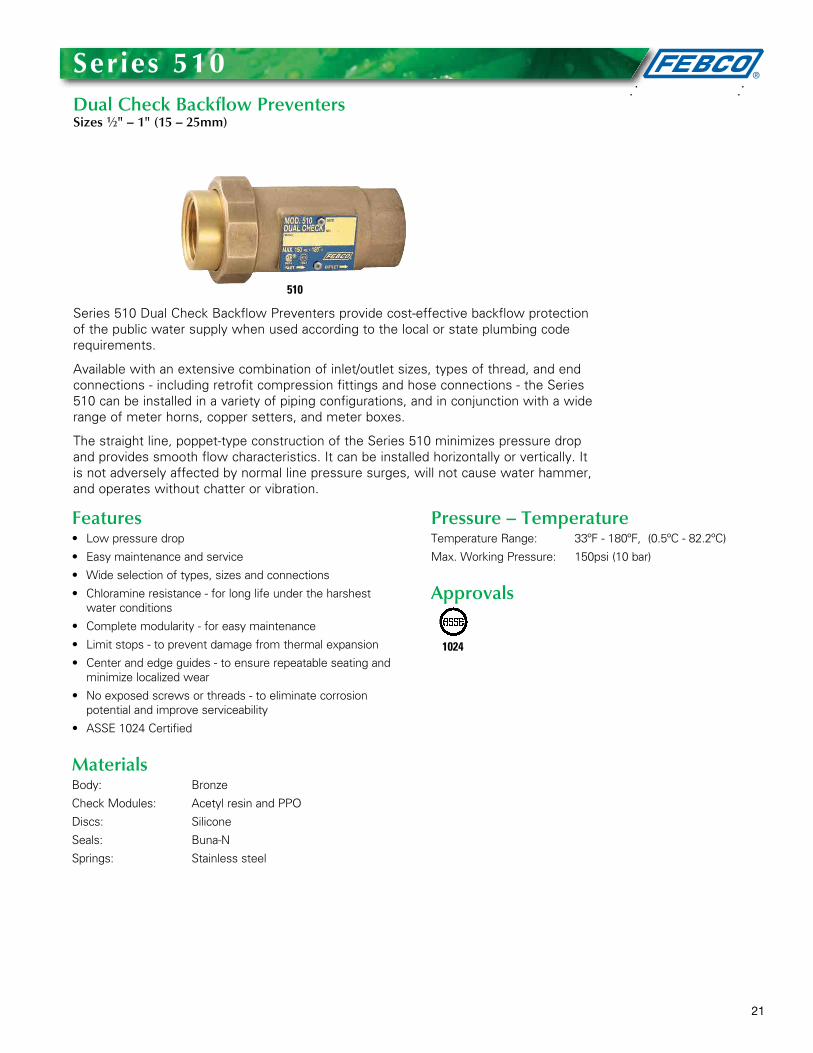
Series 510 Dual Check Backflow Preventers provide cost-effective backflow protection of the public water supply when used according to the local or state plumbing code requirements .
Available with an extensive combination of inlet/outlet sizes, types of thread, and end connections - including retrofit compression fittings and hose connections - the Series 510 can be installed in a variety of piping configurations, and in conjunction with a wide range of meter horns, copper setters, and meter boxes .
The straight line, poppet-type construction of the Series 510 minimizes pressure drop and provides smooth flow characteristics . It can be installed horizontally or vertically . It is not adversely affected by normal line pressure surges, will not cause water hammer, and operates without chatter or vibration .
Series 510Dual Check Backflow PreventersSizes 1⁄2" – 1" (15 – 25mm)
510
Features• Lowpressuredrop
• Easymaintenanceandservice
• Wideselectionoftypes,sizesandconnections
• Chloramineresistance-forlonglifeundertheharshestwater conditions
• Completemodularity-foreasymaintenance
• Limitstops-topreventdamagefromthermalexpansion
• Centerandedgeguides-toensurerepeatableseatingandminimize localized wear
• Noexposedscrewsorthreads-toeliminatecorrosionpotential and improve serviceability
• ASSE1024Certified
MaterialsBody: Bronze
Check Modules: Acetyl resin and PPO
Discs: Silicone
Seals: Buna-N
Springs: Stainless steel
Pressure – Temperature Temperature Range: 33ºF - 180ºF, (0 .5ºC - 82 .2ºC)
Max . Working Pressure: 150psi (10 bar)
Approvals
1024
22
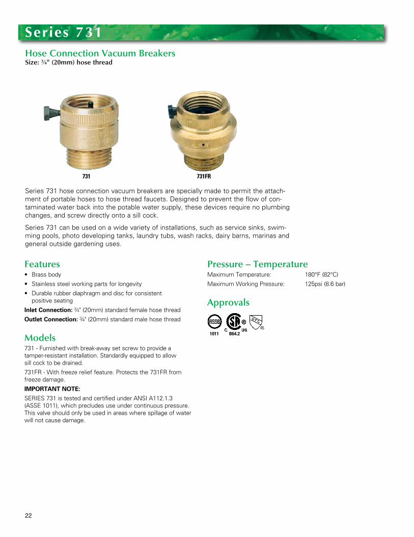
Series 731 hose connection vacuum breakers are specially made to permit the attach-ment of portable hoses to hose thread faucets . Designed to prevent the flow of con-taminated water back into the potable water supply, these devices require no plumbing changes, and screw directly onto a sill cock .
Series 731 can be used on a wide variety of installations, such as service sinks, swim-ming pools, photo developing tanks, laundry tubs, wash racks, dairy barns, marinas and general outside gardening uses .
Series 731Hose Connection Vacuum BreakersSize: 3⁄4" (20mm) hose thread
731 731FR
Features• Brassbody
• Stainlesssteelworkingpartsforlongevity
• Durablerubberdiaphragmanddiscforconsistent positive seating
Inlet Connection: 3⁄4" (20mm) standard female hose thread
Outlet Connection: 3⁄4" (20mm) standard male hose thread
Models731 - Furnished with break-away set screw to provide a tamper-resistant installation . Standardly equipped to allow sill cock to be drained .
731FR - With freeze relief feature . Protects the 731FR from freeze damage .
IMPORTANT NOTE:
SERIES 731 is tested and certified under ANSI A112 .1 .3 (ASSE 1011), which precludes use under continuous pressure . This valve should only be used in areas where spillage of water will not cause damage .
Pressure – TemperatureMaximum Temperature: 180°F (82°C)
Maximum Working Pressure: 125psi (8 .6 bar)
Approvals
1011 B64.2

23
FPHB-1
Series FPHB-1 Key Operated Wall Hydrants have been specifically designed to provide outside access to a building water supply for start-up, winterizing, and servicing of irriga-tion sprinkler systems . The FPHB-1 is located outside of the home reducing the time spent on service calls . There is no need to locate the inside shutoff valve or the drain connection . Deploying the FPHB-1 wall hydrant enables the irrigation contractor to win-terize an irrigation system at anytime thereby protecting the contractors’ warranty and the homeowners’ investment .
When used in conjunction with the FEBCO Series 767 Pressure Vacuum Breaker or either a Series 825Y or 860 Reduced Pressure Zone Backflow Preventer, the installing contractor provides affordable freeze protection for both the irrigation system and the backflow preventer .
Series FPHB-1 Key Operated Wall HydrantsSizes: 3⁄4" – 1" (20 – 25mm)
Features• Eliminatesdelaysandmultiplevisitstogaininterioraccess
to irrigation equipment
• Standardizeslocationofsupplyshutoffvalveanddrain connection
•Accessavailableanytimeforwinterizing
•Durablebronzevalvebodyandshaft
•Onepiecevalveplunger
• Tamperresistantkeyoperatedhydrant
• Exteriorchromefinish
•Resilientseatedshutoff
• Unionconnectionforeaseofinstallationofbackflow preventer
•Manualdrainport
Materials• Chromeplatedbronzevalvehead.
• Brassshaftwiththreadedend.
Pressure — TemperatureTemperature Range: 33ºF - 140ºF (0 .5ºC - 60ºC) continu-
ous, 180ºF (82ºC) intermittent
Maximum Working Pressure: 175psi (12 .1 bar)
24
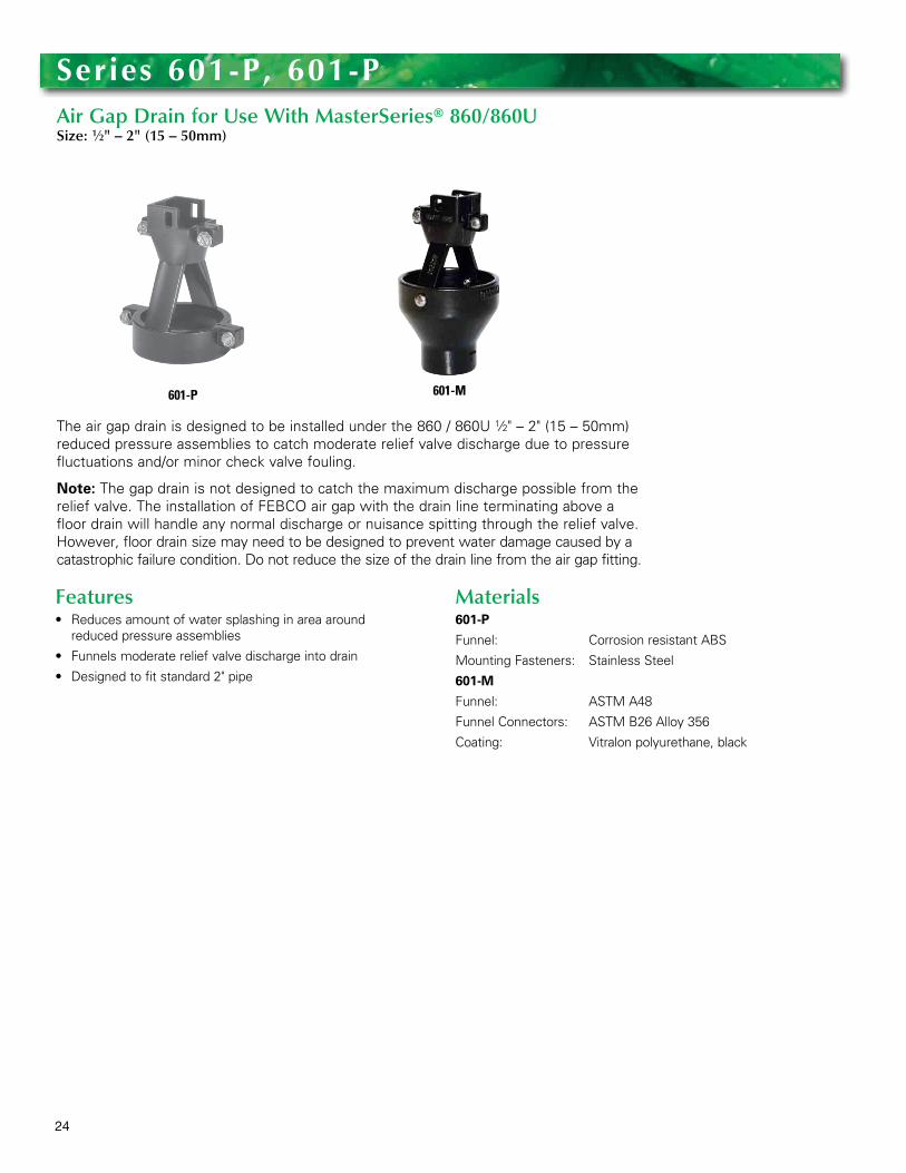
The air gap drain is designed to be installed under the 860 / 860U 1⁄2" – 2" (15 – 50mm) reduced pressure assemblies to catch moderate relief valve discharge due to pressure fluctuations and/or minor check valve fouling .
Note: The gap drain is not designed to catch the maximum discharge possible from the relief valve . The installation of FEBCO air gap with the drain line terminating above a floor drain will handle any normal discharge or nuisance spitting through the relief valve . However, floor drain size may need to be designed to prevent water damage caused by a catastrophic failure condition . Do not reduce the size of the drain line from the air gap fitting .
Series 601-P, 601-PAir Gap Drain for Use With MasterSeries® 860/860USize: 1⁄2" – 2" (15 – 50mm)
601-P
Features• Reducesamountofwatersplashinginareaaround
reduced pressure assemblies
• Funnelsmoderatereliefvalvedischargeintodrain
• Designedtofitstandard2"pipe
Materials601-P
Funnel: Corrosion resistant ABS
Mounting Fasteners: Stainless Steel
601-M
Funnel: ASTM A48
Funnel Connectors: ASTM B26 Alloy 356
Coating: Vitralon polyurethane, black
601-M
25
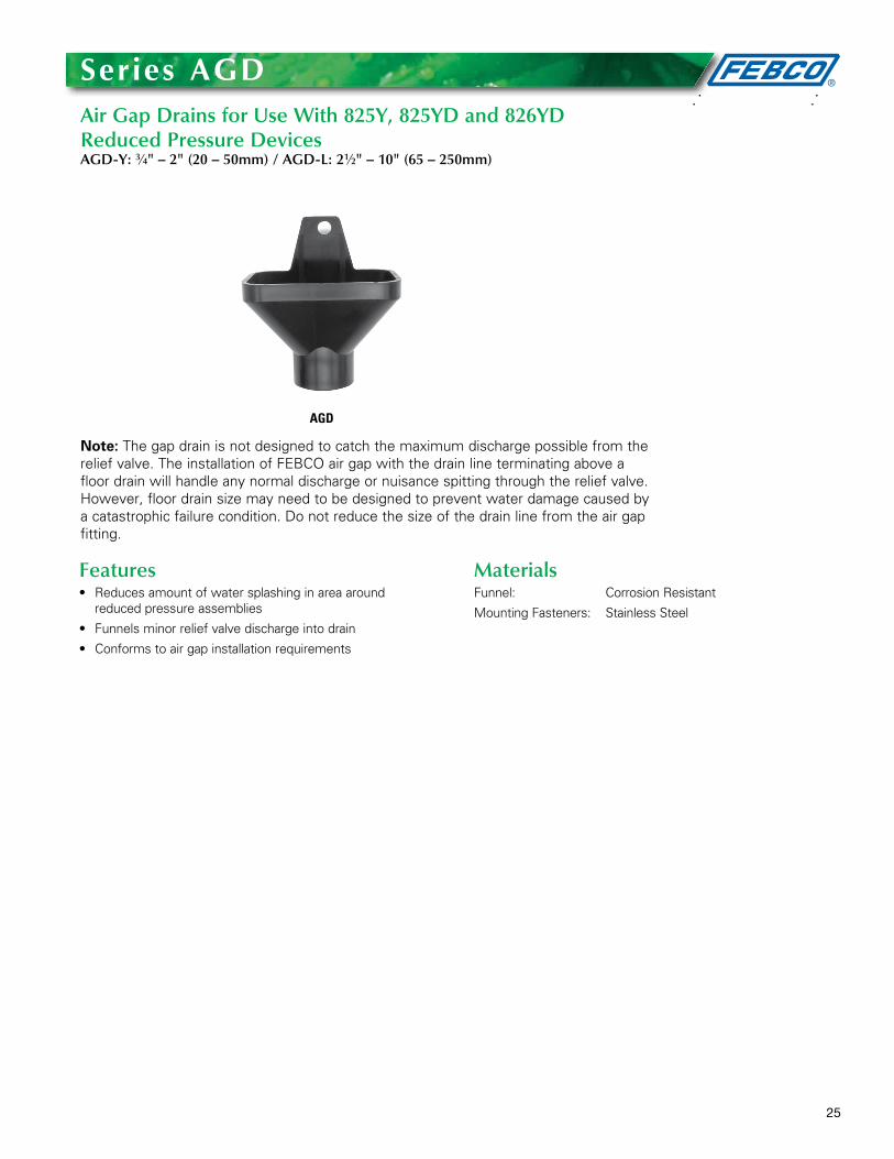
Note: The gap drain is not designed to catch the maximum discharge possible from the relief valve . The installation of FEBCO air gap with the drain line terminating above a floor drain will handle any normal discharge or nuisance spitting through the relief valve . However, floor drain size may need to be designed to prevent water damage caused by a catastrophic failure condition . Do not reduce the size of the drain line from the air gap fitting .
Series agDAir Gap Drains for Use With 825Y, 825YD and 826YD Reduced Pressure DevicesAGD-Y: 3⁄4" – 2" (20 – 50mm) / AGD-L: 21⁄2" – 10" (65 – 250mm)
AGD
Features• Reducesamountofwatersplashinginareaaround
reduced pressure assemblies
• Funnelsminorreliefvalvedischargeintodrain
• Conformstoairgapinstallationrequirements
MaterialsFunnel: Corrosion Resistant
Mounting Fasteners: Stainless Steel
26
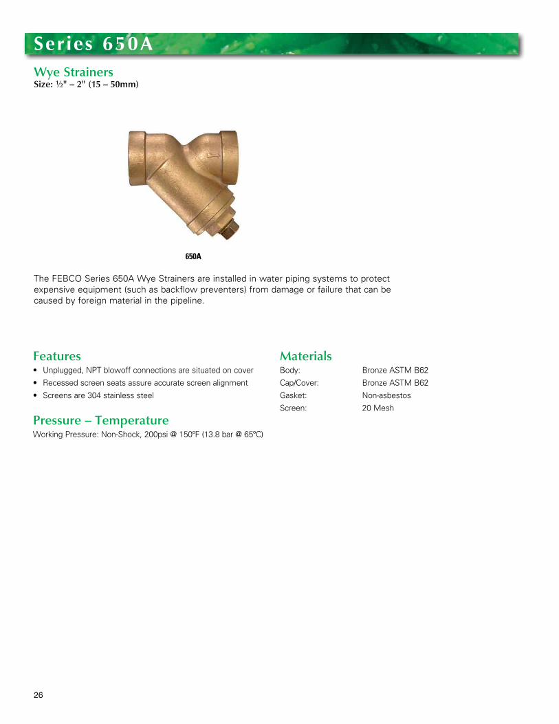
The FEBCO Series 650A Wye Strainers are installed in water piping systems to protect expensive equipment (such as backflow preventers) from damage or failure that can be caused by foreign material in the pipeline .
Series 650aWye StrainersSize: 1⁄2" – 2" (15 – 50mm)
650A
Features• Unplugged,NPTblowoffconnectionsaresituatedoncover
• Recessedscreenseatsassureaccuratescreenalignment
• Screensare304stainlesssteel
Pressure – TemperatureWorking Pressure: Non-Shock, 200psi @ 150ºF (13 .8 bar @ 65ºC)
MaterialsBody: Bronze ASTM B62
Cap/Cover: Bronze ASTM B62
Gasket: Non-asbestos
Screen: 20 Mesh
27
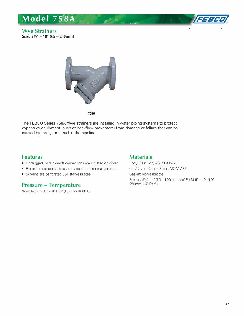
The FEBCO Series 758A Wye strainers are installed in water piping systems to protect expensive equipment (such as backflow preventers) from damage or failure that can be caused by foreign material in the pipeline .
Model 758aWye StrainersSize: 21⁄2" – 10" (65 – 250mm)
758A
Features• Unplugged,NPTblowoffconnectionsaresituatedoncover
• Recessedscreenseatsassureaccuratescreenalignment
• Screensareperforated304stainlesssteel
Pressure – TemperatureNon-Shock, 200psi @ 150º (13 .8 bar @ 60ºC)
MaterialsBody: Cast Iron, ASTM A126-B
Cap/Cover: Carbon Steel, ASTM A36
Gasket: Non-asbestos
Screen: 21⁄2" – 4" (65 – 100mm) (1⁄16" Perf .) 6" – 10" (150 – 250mm) (1⁄8" Perf .)
28
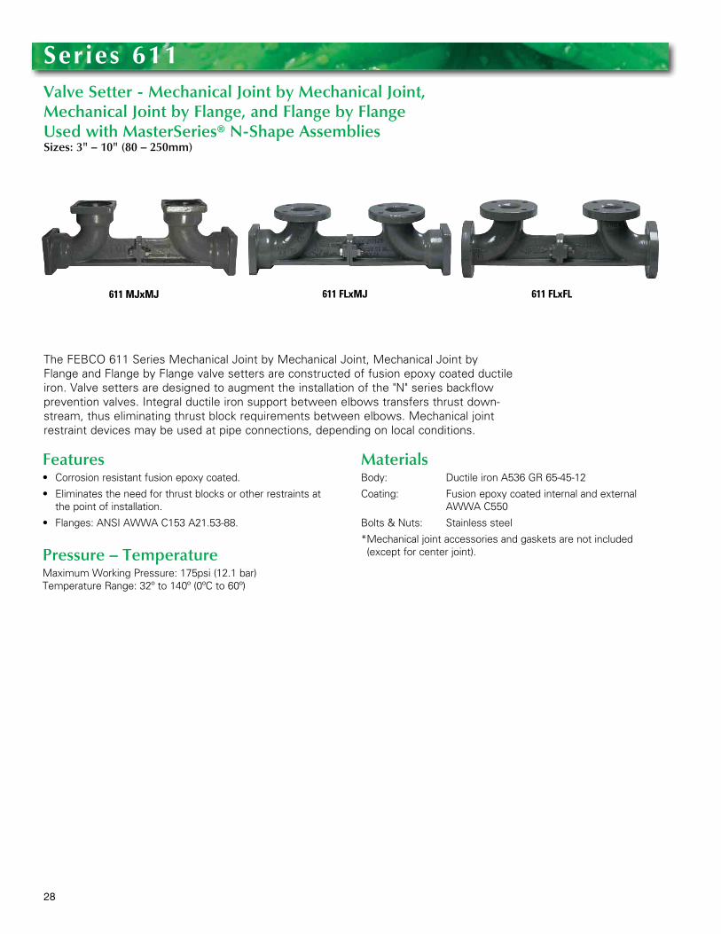
TheFEBCO611SeriesMechanicalJointbyMechanicalJoint,MechanicalJointbyFlange and Flange by Flange valve setters are constructed of fusion epoxy coated ductile iron . Valve setters are designed to augment the installation of the "N" series backflow prevention valves . Integral ductile iron support between elbows transfers thrust down-stream, thus eliminating thrust block requirements between elbows . Mechanical joint restraint devices may be used at pipe connections, depending on local conditions .
Features• Corrosionresistantfusionepoxycoated.
• Eliminatestheneedforthrustblocksorotherrestraintsatthe point of installation .
• Flanges:ANSIAWWAC153A21.53-88.
Pressure – TemperatureMaximum Working Pressure: 175psi (12 .1 bar) Temperature Range: 32º to 140º (0ºC to 60º)
MaterialsBody: Ductile iron A536 GR 65-45-12
Coating: Fusion epoxy coated internal and external AWWA C550
Bolts & Nuts: Stainless steel
* Mechanical joint accessories and gaskets are not included (except for center joint) .
Series 611Valve Setter - Mechanical Joint by Mechanical Joint, Mechanical Joint by Flange, and Flange by Flange Used with MasterSeries® N-Shape AssembliesSizes: 3" – 10" (80 – 250mm)
611 MJxMJ 611 FLxMJ 611 FLxFL
29
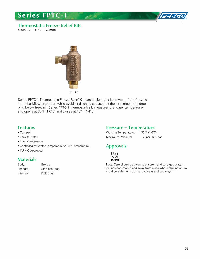
Series FPTC-1 Thermostatic Freeze Relief Kits are designed to keep water from freezing in the backflow preventer, while avoiding discharges based on the air temperature drop-ping below freezing . Series FPTC-1 thermostatically measures the water temperature and opens at 35°F (1 .6°C) and closes at 40°F (4 .4°C) .
Series FPtC-1Thermostatic Freeze Relief KitsSizes: 1⁄8" – 3⁄4" (3 – 20mm)
FPTC-1
Features•Compact
•EasytoInstall
•LowMaintenance
•ControlledbyWaterTemperaturevs.AirTemperature
•IAPMOApproved
MaterialsBody: Bronze
Springs: Stainless Steel
Internals: DZR Brass
Pressure – TemperatureWorking Temperature: 35°F (1 .6°C)
Maximum Pressure: 175psi (12 .1 bar)
Approvals
Note: Care should be given to ensure that discharged water will be adequately piped away from areas where slipping on ice could be a danger, such as roadways and pathways .
IAPMO

30
The FEBCO Model TK-1 Backflow Preventer Test Kit has been designed for simplified operation and rugged reliability in a compact package . Offering the latest in gauge tech-nology, the FEBCO TK-1 provides dependable accuracy when testing pressure vacuum breakers, anti-spill vacuum breakers, reduced pressure backflow preventers or double check assemblies and is accurate to ±1% of full scale .
Model tK-1Backflow Preventer Test Kit
TK-1
Features• Color-codedvalvesandhosesforsimplifiedoperation
• Topmounteddrain/purgevalvesandconvenientlylocatedline pressure gauge for ease of use
• Alarge4.5"anti-parallaxdialwhichindicatesdescendingmeasurement, accurate to ± 1% of full scale
• Convenientlylocatedneedlevalvesforeasyaccess
• Lightweightneedlevalvesencasedinachemical-resistantbody for trouble-free operation
• Replaceablehosefiltersandvalvestemsealsforfieldrepair
• Completekitcontainsgaugewithcolor-codedvalvesandhoses, hose adapters, shock cord for easy mounting, sup-ply pressure gauge . All contained in a durable carrying case with room for tools
Pressure – TemperatureMaximum working pressure: 200psi (13 .8 bar)
Maximum working temperature: 200°F (93ºC)

31
The FEBCO Series TC1 is designed for the following applications:• Testcockforbackflowpreventers
• Isolationvalveforgauges
• BalancingValveforgauges
Series tC1Bronze, Full Port Test CockSizes: 1⁄8" M x 1⁄4" F and 1⁄4" M x 1⁄4" F (3M x 8F and 8M x 8F mm)
TC1
Features• Bronzebody
• Fullportdesignforlowpressuredrop
• PTFEstempackingseal,thrustwasherandseat
• Quarter-turnopenorclosewithslotforcoinorscrewdriver to operate
• Idealforthrottlingandbalancingapplicationsofnon-abra-sive fluids where flow is 20% to 100% of valve capacity
• Lowoperatingtorque
32
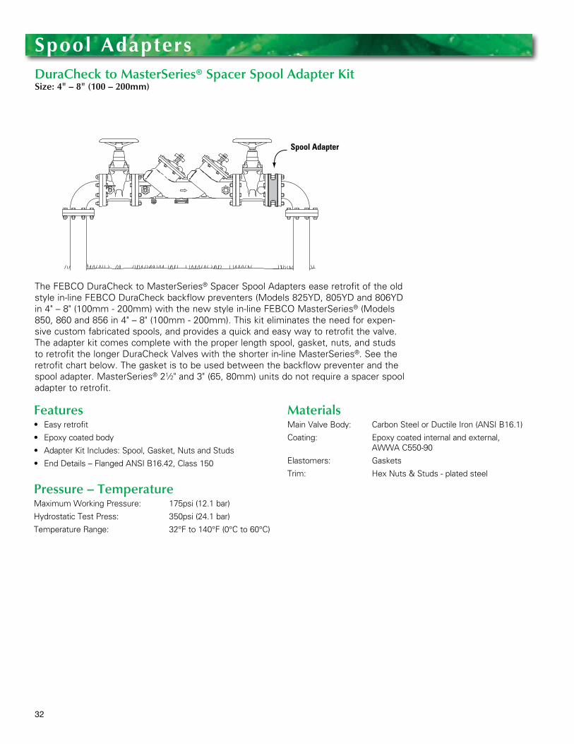
The FEBCO DuraCheck to MasterSeries® Spacer Spool Adapters ease retrofit of the old style in-line FEBCO DuraCheck backflow preventers (Models 825YD, 805YD and 806YD in 4" – 8" (100mm - 200mm) with the new style in-line FEBCO MasterSeries® (Models 850, 860 and 856 in 4" – 8" (100mm - 200mm) . This kit eliminates the need for expen-sive custom fabricated spools, and provides a quick and easy way to retrofit the valve . The adapter kit comes complete with the proper length spool, gasket, nuts, and studs to retrofit the longer DuraCheck Valves with the shorter in-line MasterSeries® . See the retrofit chart below . The gasket is to be used between the backflow preventer and the spool adapter . MasterSeries® 21⁄2" and 3" (65, 80mm) units do not require a spacer spool adapter to retrofit .
Spool adapters DuraCheck to MasterSeries® Spacer Spool Adapter KitSize: 4" – 8" (100 – 200mm)
Features• Easyretrofit
• Epoxycoatedbody
• AdapterKitIncludes:Spool,Gasket,NutsandStuds
• EndDetails–FlangedANSIB16.42,Class150
Pressure – TemperatureMaximum Working Pressure: 175psi (12 .1 bar)
Hydrostatic Test Press: 350psi (24 .1 bar)
Temperature Range: 32°F to 140°F (0°C to 60°C)
MaterialsMain Valve Body: Carbon Steel or Ductile Iron (ANSI B16 .1)
Coating: Epoxy coated internal and external, AWWA C550-90
Elastomers: Gaskets
Trim: Hex Nuts & Studs - plated steel
Spool Adapter
33
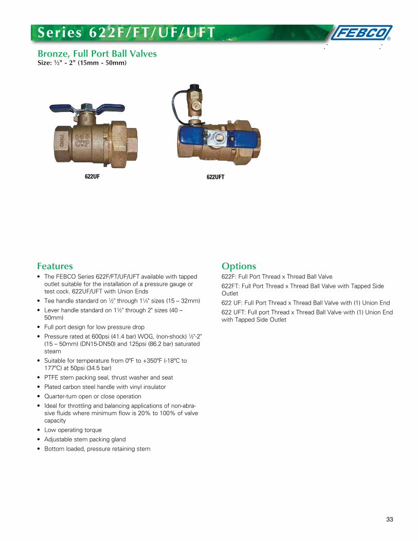
Series 622F/Ft/UF/UFtBronze, Full Port Ball ValvesSize: 1⁄2" - 2" (15mm - 50mm)
622UF 622UFT
Features• TheFEBCOSeries622F/FT/UF/UFTavailablewithtapped
outlet suitable for the installation of a pressure gauge or test cock . 622UF/UFT with Union Ends
• Teehandlestandardon1⁄2" through 11⁄4" sizes (15 – 32mm)
• Leverhandlestandardon11⁄2" through 2" sizes (40 – 50mm)
• Fullportdesignforlowpressuredrop
• Pressureratedat600psi(41.4bar)WOG,(non-shock)1⁄2"-2" (15 – 50mm) (DN15-DN50) and 125psi (86 .2 bar) saturated steam
• Suitablefortemperaturefrom0ºFto+350ºF(-18ºCto177ºC) at 50psi (34 .5 bar)
• PTFEstempackingseal,thrustwasherandseat
• Platedcarbonsteelhandlewithvinylinsulator
• Quarter-turnopenorcloseoperation
• Idealforthrottlingandbalancingapplicationsofnon-abra-sive fluids where minimum flow is 20% to 100% of valve capacity
• Lowoperatingtorque
• Adjustablestempackinggland
• Bottomloaded,pressureretainingstem
Options622F: Full Port Thread x Thread Ball Valve
622FT: Full Port Thread x Thread Ball Valve with Tapped Side Outlet
622 UF: Full Port Thread x Thread Ball Valve with (1) Union End
622 UFT: Full port Thread x Thread Ball Valve with (1) Union End with Tapped Side Outlet

34
Series 623-BS 2-piece, full port, brass ball valves are used in commercial and industrial applications for a full range of liquids and gases . They feature a bottom-loaded blowout proof stem, virgin PTFE seats, thrust washer, and adjustable stem packing gland, stem packing nut, chrome plated brass ball, brass adapter, and steel handle .
Series 623-BS2-Piece, Full Port, Brass Ball ValvesSizes: 1/4" – 3" (8 – 80mm)
623-BS
Features• CertifiedtoNSF/ANSIstandard61/8
• CSAapproved1⁄2" – 3" (15 – 80mm)
• UL/FMapproved1⁄2" – 2" (15 – 50mm)
• Metal-to-metaladapterbodysealpreventsadapterleaks
• FluorocarbonelastomerstemO-ringpreventsstemleaks
• Adjustablestempackinggland
• VirginPTFEstempackingseal,thrustwasher,andseats
• Bottomloadedblowoutproofstem
• Machinedchromeplatedbrassball
• ValvescomplytoMSS-SP-110standard
Models623-BS: 1⁄4" – 3" (8 – 80mm) with NPT threaded connections
Pressure – TemperatureTemperature Range: -40ºF to 400ºF (-40ºC to 204ºC)
Pressure Ratings623-BS : 1⁄4" – 2" (8 – 50mm)
600psi (41 bar) WOG, non-shock 150psi (10 .3 bar) WSP
21⁄2" – 3" (65 – 80mm) 600psi (41 bar) WOG, non-shock 125psi (8 .6 bar) WSP
Approvals 1⁄4" – 2" (8 - 80mm) 623-BS Certified to NSF/ANSI standard 61/81⁄2" – 2" (15 – 50mm) 623-BS UL/FM approved
Gas Approvals1⁄2" – 2" (15 – 50mm)
ASME B16 .33, CSA
1⁄2 psig, 5psig, and 125psig (14, 34 and 862 kPa)
@ -40ºF to 125ºF (-40ºC - 52ºC)
21⁄2" – 3" (65 – 88mm)
ASME B16 .38, CSA1⁄2 psig, 5psig, and 125psig (14, 34 and 862 kPa)
@ -40ºF to 125ºF (-40ºC - 52ºC)
approved
35
Features• Threadedbonnet
• Non-risingstem
• Solidwedgedisc
• Brassbody
• 3⁄8" - 3" (10 - 80mm) threaded end connections
Pressure — Temperature• 200psi(13.8bar)WOGnon-shockto180°F(82°C)
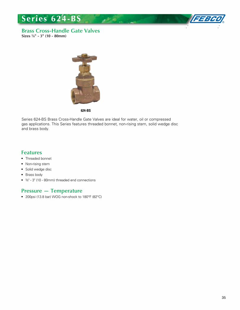
Series 624-BS Brass Cross-Handle Gate Valves are ideal for water, oil or compressed gas applications . This Series features threaded bonnet, non-rising stem, solid wedge disc and brass body .
Series 624-BSBrass Cross-Handle Gate ValvesSizes 3⁄8" - 3" (10 - 80mm)
624-BS
36
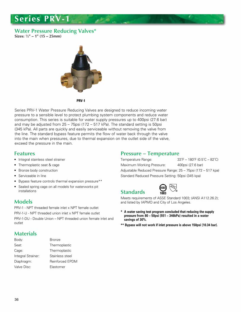
Series PRV-1 Water Pressure Reducing Valves are designed to reduce incoming water pressure to a sensible level to protect plumbing system components and reduce water consumption . This series is suitable for water supply pressures up to 400psi (27 .6 bar) and may be adjusted from 25 – 75psi (172 – 517 kPa) . The standard setting is 50psi (345 kPa) . All parts are quickly and easily serviceable without removing the valve from the line . The standard bypass feature permits the flow of water back through the valve into the main when pressures, due to thermal expansion on the outlet side of the valve, exceed the pressure in the main .
Series PrV-1Water Pressure Reducing Valves*Sizes: 1⁄2" – 1" (15 – 25mm)
PRV-1
Features• Integralstainlesssteelstrainer
• Thermoplasticseat&cage
• Bronzebodyconstruction
• Serviceableinline
• Bypassfeaturecontrolsthermalexpansionpressure**
• Sealedspringcageonallmodelsforwaterworkspit installations
ModelsPRV-1 - NPT threaded female inlet x NPT female outlet
PRV-1-U - NPT threaded union inlet x NPT female outlet
PRV-1-DU - Double Union – NPT threaded union female inlet and outlet
MaterialsBody: Bronze
Seat: Thermoplastic
Cage: Thermoplastic
Integral Strainer: Stainless steel
Diaphragm: Reinforced EPDM
Valve Disc: Elastomer
Pressure – TemperatureTemperature Range: 33˚F – 180˚F (0 .5˚C – 82˚C)
Maximum Working Pressure: 400psi (27 .6 bar)
Adjustable Reduced Pressure Range: 25 – 75psi (172 – 517 kpa)
Standard Reduced Pressure Setting: 50psi (345 kpa)
StandardsMeets requirements of ASSE Standard 1003; (ANSI A112 .26 .2); and listed by IAPMO and City of Los Angeles .
* A water saving test program concluded that reducing the supply pressure from 80 – 50psi (551 – 346kPa) resulted in a water savings of 30%.
** Bypass will not work if inlet pressure is above 150psi (10.34 bar).
1003
37
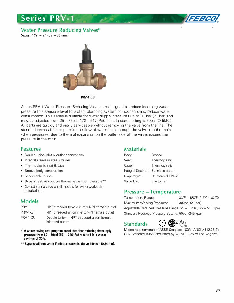
Series PRV-1 Water Pressure Reducing Valves are designed to reduce incoming water pressure to a sensible level to protect plumbing system components and reduce water consumption . This series is suitable for water supply pressures up to 300psi (21 bar) and may be adjusted from 25 – 75psi (172 – 517kPa) . The standard setting is 50psi (345kPa) . All parts are quickly and easily serviceable without removing the valve from the line . The standard bypass feature permits the flow of water back through the valve into the main when pressures, due to thermal expansion on the outlet side of the valve, exceed the pressure in the main .
Series PrV-1Water Pressure Reducing Valves*Sizes: 11⁄4" – 2" (32 – 50mm)
PRV-1-DU
Features• Doubleunioninlet&outletconnections
• Integralstainlesssteelstrainer
• Thermoplasticseat&cage
• Bronzebodyconstruction
• Serviceableinline
• Bypassfeaturecontrolsthermalexpansionpressure**
• Sealedspringcageonallmodelsforwaterworkspit installations
ModelsPRV-1 NPT threaded female inlet x NPT female outlet
PRV-1-U NPT threaded union inlet x NPT female outlet
PRV-1-DU Double Union – NPT threaded union female inlet and outlet
* A water saving test program concluded that reducing the supply pressure from 80 – 50psi (551 – 346kPa) resulted in a water savings of 30%.
** Bypass will not work if inlet pressure is above 150psi (10.34 bar).
MaterialsBody: Bronze
Seat: Thermoplastic
Cage: Thermoplastic
Integral Strainer: Stainless steel
Diaphragm: Reinforced EPDM
Valve Disc: Elastomer
Pressure – TemperatureTemperature Range: 33˚F – 180˚F (0 .5˚C – 82˚C)
Maximum Working Pressure: 300psi (21 bar)
Adjustable Reduced Pressure Range: 25 – 75psi (172 – 517 kpa)
Standard Reduced Pressure Setting: 50psi (345 kpa)
StandardsMeets requirements of ASSE Standard 1003; (ANSI A112 .26 .2); CSA Standard B356; and listed by IAPMO . City of Los Angeles .

38
Series PRV-2 Water Pressure Reducing Valves are designed to reduce incoming water pressure to a sensible level to protect plumbing system components and reduce water consumption . This series is suitable for water supply pressures up to 400psi (27 .6 bar) and may be adjusted from 25 to 75psi (172 – 517kPa) . The standard setting is 50psi (345kPa) . All parts are quickly and easily serviceable without removing the valve from the line . The standard bypass feature permits the flow of water back through the valve into the main when pressures, due to thermal expansion on the outlet side of the valve, exceed the pressure in the main .
Series PrV-2Water Pressure Reducing Valves*Sizes: 1⁄2" – 1" (15 – 25mm)
PRV-2-U
Features•Integralstainlesssteelstrainer
•Thermoplasticseat
•Bronzebodyconstruction
•Serviceableinline
•Bypassfeaturecontrolsthermalexpansionpressure**
•Sealedspringcageonallmodelsforwaterworkspit installations
ModelsPRV-2 – NPT threaded female inlet x NPT female outlet
PRV-2-U – NPT threaded union inlet x NPT female outlet
PRV-2-DU – Double Union – NPT threaded union female inlet and outlet
* A water saving test program concluded that reducing the supply pressure from 80 – 50psi (551 – 346kPa) resulted in a water savings of 30%.
** Bypass will not work if inlet pressure is above 150psi (10.34 bar).
MaterialsBody: Bronze
Seat: Thermoplastic
Cage: Bronze
Integral Strainer: Stainless steel
Diaphragm: Reinforced EPDM
Valve Disc: Elastomer
Pressure — TemperatureTemperature Range: 33°F – 180°F (0 .5°C – 82°C)
Maximum Working Pressure: 400psi (27 .6 bar)
Adjustable Reduced Pressure Range: 25 – 75psi (172 – 517kPa)
Standard Reduced Pressure Setting: 50psi (345kPa)
StandardsMeets requirements of ASSE Standard 1003; (ANSI A112 .26 .2); listed by IAPMO and City of Los Angeles .
1003
39
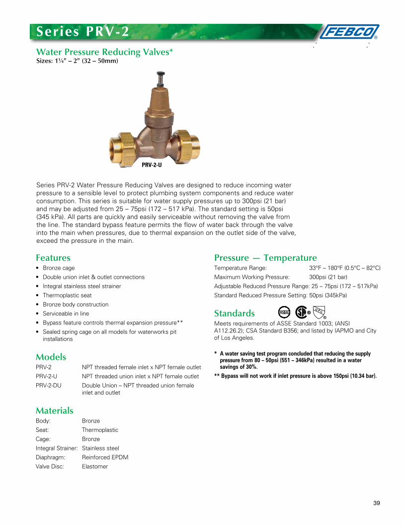
Series PRV-2 Water Pressure Reducing Valves are designed to reduce incoming water pressure to a sensible level to protect plumbing system components and reduce water consumption . This series is suitable for water supply pressures up to 300psi (21 bar) and may be adjusted from 25 – 75psi (172 – 517 kPa) . The standard setting is 50psi (345 kPa) . All parts are quickly and easily serviceable without removing the valve from the line . The standard bypass feature permits the flow of water back through the valve into the main when pressures, due to thermal expansion on the outlet side of the valve, exceed the pressure in the main .
Series PrV-2Water Pressure Reducing Valves*Sizes: 11⁄4" – 2" (32 – 50mm)
PRV-2-U
Features• Bronzecage
• Doubleunioninlet&outletconnections
• Integralstainlesssteelstrainer
• Thermoplasticseat
• Bronzebodyconstruction
• Serviceableinline
• Bypassfeaturecontrolsthermalexpansionpressure**
• Sealedspringcageonallmodelsforwaterworkspit installations
ModelsPRV-2 NPT threaded female inlet x NPT female outlet
PRV-2-U NPT threaded union inlet x NPT female outlet
PRV-2-DU Double Union – NPT threaded union female inlet and outlet
MaterialsBody: Bronze
Seat: Thermoplastic
Cage: Bronze
Integral Strainer: Stainless steel
Diaphragm: Reinforced EPDM
Valve Disc: Elastomer
Pressure — TemperatureTemperature Range: 33°F – 180°F (0 .5°C – 82°C)
Maximum Working Pressure: 300psi (21 bar)
Adjustable Reduced Pressure Range: 25 – 75psi (172 – 517kPa)
Standard Reduced Pressure Setting: 50psi (345kPa)
StandardsMeets requirements of ASSE Standard 1003; (ANSI A112 .26 .2); CSA Standard B356; and listed by IAPMO and City of Los Angeles .
* A water saving test program concluded that reducing the supply pressure from 80 – 50psi (551 – 346kPa) resulted in a water savings of 30%.
** Bypass will not work if inlet pressure is above 150psi (10.34 bar).
40
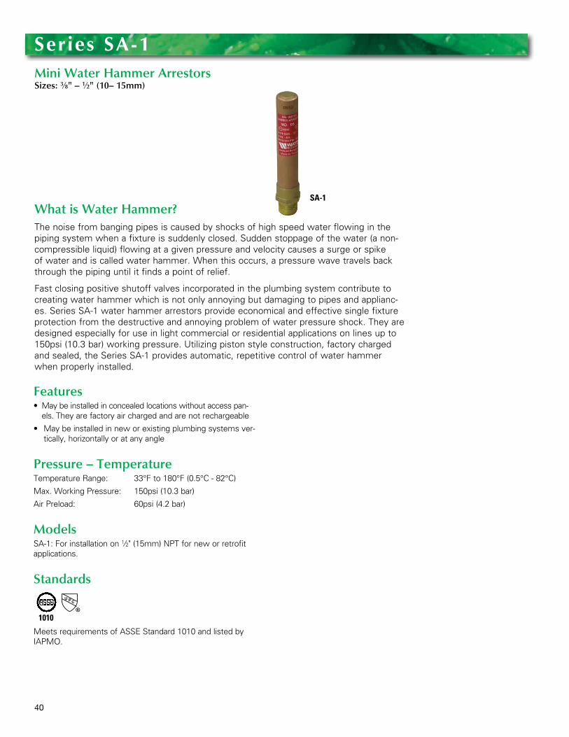
What is Water Hammer?The noise from banging pipes is caused by shocks of high speed water flowing in the piping system when a fixture is suddenly closed . Sudden stoppage of the water (a non-compressible liquid) flowing at a given pressure and velocity causes a surge or spike of water and is called water hammer . When this occurs, a pressure wave travels back through the piping until it finds a point of relief .
Fast closing positive shutoff valves incorporated in the plumbing system contribute to creating water hammer which is not only annoying but damaging to pipes and applianc-es . Series SA-1 water hammer arrestors provide economical and effective single fixture protection from the destructive and annoying problem of water pressure shock . They are designed especially for use in light commercial or residential applications on lines up to 150psi (10 .3 bar) working pressure . Utilizing piston style construction, factory charged and sealed, the Series SA-1 provides automatic, repetitive control of water hammer when properly installed .
Series Sa-1Mini Water Hammer ArrestorsSizes: 3⁄8" – 1⁄2" (10– 15mm)
SA-1
Features • Maybeinstalledinconcealedlocationswithoutaccesspan-
els . They are factory air charged and are not rechargeable
• Maybeinstalledinneworexistingplumbingsystemsver-tically, horizontally or at any angle
Pressure – TemperatureTemperature Range: 33°F to 180°F (0 .5°C - 82°C)
Max . Working Pressure: 150psi (10 .3 bar)
Air Preload: 60psi (4 .2 bar)
ModelsSA-1: For installation on 1⁄2" (15mm) NPT for new or retrofit applications .
Standards
Meets requirements of ASSE Standard 1010 and listed by IAPMO .
1010


Winter Protection for PVB, DC and rPFEBCO makes it easy to bring backflow preventers in out of the cold during the winter season with the Union-Endoptionforirrigationvalves.Youcancom-pletely eliminate the potential for twisted or warped internals caused by freezing temperatures and the time and expense needed for repair or replacement. With the Union-End option on Models 765,850and860, there’llbenomore springsurprises, just a backflow preventer that is ready to go back to work.
Contact UsFor technical, repair, approval, and war-ranty information on FEBCO products contact your local FEBCO representative or visit www.FEBCOonline.com.
A Watts Water Technologies Company USA: Tel: (559) 441-5300 • Fax: (559) 441-5301 • www.FEBCOonline.comCanada: Tel: (905) 332-4090 • Fax: (905) 332-7068 • www.FEBCOonline.ca
PG-F-Irrigation 1238 © 2012 FEBCO