irste journal colour · 3.1 track circuits basic safety device which gives track vacancy at a...
TRANSCRIPT

ND T A EL LA ECN OGI MS MY UA NW IL CI AA TR IOF NO EN NOI GT INU ETI ET RS SNI
(INDIA)
I N S T I T U T I O N O FRAILWAY SIGNAL AND TELECOMMUNICATIONENGINEERS
IRSTE(INDIA)
IRSTE JOURNALJanuary - March, 2014Year - X Volume - I
ND T A EL LA ECN OGI MS MY UA NW IL CI AA TR IOF NO EN NOI GT INU ETI ET RS SNI
(INDIA)
I N S T I T U T I O N O FRAILWAY SIGNAL AND TELECOMMUNICATIONENGINEERS
IRSTE(INDIA)
IRSTE NEWS is published quarterly by the Institution of R a i l w a y S i g n a l a n d Telecommunication Engineers (IRSTE).
© Copyright 2007, IRSTE. All rights reserved. No part of this publication may be reproduced, stored in a retrieval system, or transmitted in any form or by any means without the permission in writing of the publisher. Copying of articles is not permitted except for personal and internal use. Multiple copying of the contents of this publication without permission is always illegal.
Vikas SrivastavaGautam Arora
S. P. Beck
Articles of a newsworthy or technical nature are always welcome for IRSTE NEWS.
Members should fowards their contributions to one of the
Editors shown above.
For details of advertising rates and deadlines call
Amit MehrotraSr. DSTE/Delhi
9717631800
For up to date information about Institution or its activities, or to
download a membership application form, log on to the
IRSTE Web Site at :
Editors
Assistant Editor
Contributions
Advertising
Web Site
www.irsteindia.com
OFFICE BEARERS OF THE INSTITUTION OF RLY. SIGNALLING & TELECOM ENGINEERS (INDIA) HEAD QUARTERS
PATRON
Hony. President
Hony. Vice President
Hony. Secretary
Hony. Treasurer
Hony. Joint Secretary
ALLAHABAD CHAPTER :
BHUVANESHWAR CHAPTER :
CHENNAI CHAPTER :
DELHI CHAPTER :
GUWAHATI CHAPTER :
GORAKHPUR CHAPTER
HUBLI CHAPTER :
JABALPUR CHAPTER :
JAIPUR CHAPTER :
KOLKATA CHAPTER :
LUCKNOW CHAPTER :
MUMBAI CHAPTER :
SECUNDERABAD CHAPTER :
: Shri Kulbhushan, Member Electrical, Railway Board
: Shri M. Suresh, AM / Signal, Railway Board
: Shri P. K. Srivastava, AM / Tele, Railway Board
: Shri Kundan Chaudhary, CAO / IRPMU
: Shri Anshul Gupta, ED / CC and CVO, RailTel
: Shri Gautam Arora, GM / S&T / DFCCIL
President : Shri D. K. Gupta, CSTE / CORE
President : Shri S. H. Safdar, CSTE / ECOR
President : Shri S. Manohar, CSTE / SR
President : Shri Akhil Aggarwal, CSTE / NR
President : Shri O. P. Verma, CSTE / NFR
President : Shri H. K. Aggarwal, CSTE / NER
President : Shri Lakshmi Narayana, CSTE / SWR
President : Shri S. P. Trivedi, CSTE / WCR
President : Shri Mahesh Mehta, CSTE / NWR
President : Shri S. K. Mandal, CSTE / ERPresident : Ms. AV. Siva Prasad, CSTE / SER
President : Shri Mahesh Mangal, Sr. ED (Sig) RDSO
President : Shri K. S. Krishna Kumar, CSTE / CRPresident : Shri G. S. Tuteja, CSTE / WR
President : Shri M. Alam, CSTE / SCRPresident : Shri Satyendra Kumar, Director / IRISET
IN THIS ISSUE Page No.
General Secretary's Letter1. 2
Evolution of Signalling on Indian Railways & Road Ahead for Radio Based Signalling
2. 3
M. Suresh
Train Collision Avoidance System (TCAS)3.Lalit Mansukhani
11
Multilevel Railway Traffic Interval Control and Safety System (MICSS)
4. 19
Research and Development Institute for Railway Automatics
IRSTE (India) Activities on Indian Railways2013-14 - April-June 2013 progress
5. 22
Dear Members,
Indian Railway's Signaling & Telecommunication Department is now being faced with many challenges. The challenge is not only to implement the sanctioned projects but also to develop capacity in the corporate world to carry out these works.
I hope that the contents in the Journal will be useful to Signaling & Telecommunications professionals working on various Railways. I also request that Signaling & Telecommunications officers should come forward and write articles on the activities being done by them.
(Kundan Chaudhary)Secretary, IRSTE (India)
& Chief Administrative Officer/IRPMU
From the Desk of President

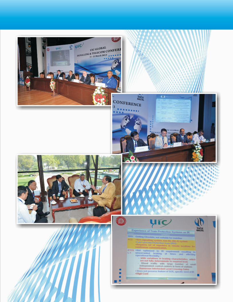
Evolution of Signalling on Indian Railways & Road Ahead for Radio Based Signalling
M. SureshAdditional Member (Signal)Railway Board, India
(As presented during 3rd UIC Global Signalling and Telecom Conference)
1. Introduction
2. Growth of Signalling on Indian Railways
3. Safety Enhancement at Stations
1.1 Indian Railways came into existence on 16th April, 1853 with historical journey between Bombay and Thane a distance of about 30 Km hauled by three locomotives Sultan, Sindh and Sahib with 14 coaches and 400 guests.
1.2 First time in the year 1894, List and Morse interlocking system was installed at 28 crossing stations between Lahore and Ghaziabad.
1.3 By end of 1900, 600 stations were provided with some sort of interlocking arrangements between points and signals
1.4 Colour Light Signalling was introduced on Indian Railways in 1928 between Bombay VT and Byculla stations. Block Instruments were standardised in 1930s and Block Signalling Manual was framed.
2.1 To meet Operational and Safety needs of ever increasing growth of train traffic, Indian Railways have been steadily modernizing its Signalling assets.
2.2 With the inescapable role of Railway Signalling in train operations and availability of modern technologies, Signalling arrangements are poised for quantum jump in the years to come.
2.3 The paper covers various modern Signalling arrangements which are currently being provided alongwith induction and introduction of advanced technologies.
3.1 Track CircuitsBasic safety device which gives track vacancy at a station. Out of 6008 BG stations, complete track circuiting has been provided at 5200 stations.
Balance track circuits either by means of DCtrack circuit or Digital Axle Counters shall be provided in the next two years time.
3.2 Colour Light LED SignalsFilament incandescent lamps,double filament triple pole lamps, requiring frequent replacement and low luminosity were provided earlier. Now LED Signals with high visibility and longer life have been provided at 5200 stations which besides reducingmaintenance efforts has givenmore confidenceto loco pilots.
3.3 Interlocking SystemInspite of ongoing modernisation in Signalling by provision of Electronic/Relay Interlocking IR still has a largenumber of orthodox mechanical lever frames for operating Semaphore Signals or Colour Light Signals. Electronic Interlocking is now being implemented and Signal Engineers have gained confidence for inducting Electronic Interlocking.Research Design & Standards Organisation(RDSO) has played a vital role in framing specificationsand issuing Technical approvals for Electronic Interlocking being provided on Indian Railways. We still have a lot of dependence on the Industry which is expected to reduce in the years to come. Regular training courses are being conducted at OEM's premises and at Indian Railway Institute of Signal Engineering & Telecommunication (IRISET) where select officers and staff are being trained in a professional manner
3.2 Data LoggersIt is a Diagnostic equipment used for logging status of vital Signalling gears installed at a station through potential free relay contacts and helps in Real Time Monitoring of Signalling gears. Data Loggers are being widely based for analysis of signal failures, predictive and preventive maintenance. Analysis is also done for cases of unusual incidences of SPAD, train accidents –
wherein the events can be stimulated and played back to ascertain clearance of signals, occupation of track circuits, movement of points etc. It has also been found useful to monitor compliance of prescribed operational rules like setting of points against occupied line, testing of emergency cross-overs etc. Data Loggers at stations have been networked to all Divisional Headquarters and networking to Zonal Headquarters shall be completed in the next three months.
3.5 Implementation of these measures has drastically brought down train collisions
4.1 Block Proving by Axle Counters (BPAC)With increased traffic density and emphasis on Safety instead of manual verification of complete arrival of train at a station, automatic verification through Axle Counters is being progressively provided. Work at 50% of Bock Sections has been completed and balance is planned for completion in the next 5 years. In all new and replacement works of EI/RRI, BPAC provision has been made mandatory.
4. Safety Enhancement in Block Sections
4.2 Interlocking of Level Crossing GatesSafety at Level Crossing gates is enhanced by manning, interlocking and provision of telephones. Accidents of Level Crossings have shown a decline by these methods. All manned LCs have been provided. with telephones.
5.1 Intermediate Block Signalling (IBS) Splitting of long Block sections by provision of IBS is being done. So far 416 IBSshave been provided and another 100 are planned to be provided in the next three years.
5.2 Automatic SignallingCost effective tool for enhancing line capacity. Plays a vital role in train operations in suburban sectionof Kolkata, Chennai and Mumbai where trains run at close intervals. Auto Signalling on a continuous stretch in Mumbai-Ahmedabad (500 Km) and Kanpur-Aligarh(300 km) sections have recently been completed.
5.3 Growth of Signalling over the last 30 years for line capacity and Safety Enhancement are given in the tables alongwith Projection for XII Five Year Plan.
5. Line Capacity Enhancement
INDIAN RAILWAYS- ZONAL HEADQUARTERS

General Data of Indian Railways
Type of Data 1982 1992 2002 2012
Passenger Trains (BG &
MG) in Nos.
6251
7284
8702
12190
Freight Traffic Net
TonneKms Billions
172.2
256.9
336.4
668.6
Railway Network in RKM
61230
62458
63140
64600
Single Line Network in RKM
48089
47853
47016
45232
Double/Multiple Line
Network in RKM
13141
14605
16124
19368
Growth of Signalling on Indian Railways
ITEM Mar, 82 Mar, 92 Mar, 02 Mar, 12 Dec, 12
Interlocked Stations(BG) 3173 4088 5003 6008 6008
Panel Interlocking (Stns)
417
1212
2265
4079 4169
Route Relay Interlocking (Stns)
98
144
188
257
261
Electronic Interlocking (Stns)
14
535
592
PI/RRI/EI
515
1356
2467
4871
5022
MAUQ/LQ (Stns)
1450
1905
1891
395
364
MACLS with Lever frame (Stns)
564
827
645
520
454
MACLS (Stns)
1079
2183
3112
5391
5476
Track Circuiting (Locations) 3983 8930 17078 29201 29741

6. Automatic Train Protection Systems
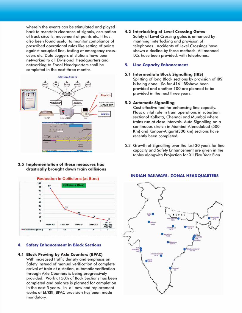
6.1 Auxiliary Warning System (AWS)A reliable method for ensuring loco pilot failures to observe and obey Signal is the Auxiliary Warning System (AWS). Loco equipment interfaced with brake system and activated by the track device prevents Signal Passing at Danger. It is a track magnet system which takes inputs of the Signal aspects and is working in Mumbai Suburban sections of Western and Central Railways ona network of 329 RKm where trains run at a close headway of 3 to 4 minutes. This has been provided only on the EMUs. System applies brakes automatically in case motorman disregards a 'Red' Signal. Speed of the train is regulated on the 'Yellow' aspect. AWS has been working satisfactorily since its installation in the 1990s where presently 2800 train suburban services are run daily carrying about seven million passengers.
6.2 Anti Collision Device (ACD)Works on Global Positioning System (GPS) and Angular Deviation Count principle. Signalling inputs of Main Line Track Circuit and First facing point 'N' or 'R' are taken. It is a single vendor microprocessor based equipment to present Head on, side and rear end collisions at High Speed and also provides
Projections for XII Five Year Plan
SN Item Target
1 Replacement of Relay Based Interlocking with EI (stns) 1200
2 Replacement of Over-aged ABS, IBS etc. (RKM) 600
3 Complete Track circuiting of Balance stations (stns) 700
4 BPAC at balance Block sections (Block Sections) 3000
5 Provision of Data Logger & Networking (no.) 1200
6 Provision of Isolation of run -through lines &
upgradation from STD I to STD IIR (stns)
630
7 Automatic Block Signalling on selected sections of A, B
& C routes (RKM)
2000
Approach Warning at Level Crossing Gates. Mobile ACDs are fitted on Loco/Guard(Cabins) and stationary ACDs at stations and Level Crossing gates. ACDs communicate with each other in 3 Km range and On Board microprocessor assess emerging scenario and applies brakes in collision like situation. Manual SOS facility from loco as well as from stations is available wherein automatic application of brakes takes place in the locos on receiving the SOS signal. This has been operationalised in 2006 on 1740 Rkm on BG section of Northeast Frontier Railway.A new and improved ACD software version is under implementation to take care of unwarranted brakings, loco ACD restarts, frequent thefts of mid section repeaters etc. It has not been found suitable for Automatic, Electrified and multiple line sections.
6.3 Train Protection Warning System (TPWS) – ETCS Level 1
Two pilot projects for implementation of European Train Control System Level 1 have been completed on Indian Railways. Eurobalises with standard interfacing telegram structure communicating to the On Board computer for giving necessary inputs to Driver Machine Interface(DMI) and Brake interface have been deployed. The system has been found useful in prevention of SPAD due to human error and has continuous speed supervision. Enforcement of Permanent Speed Restrictions has also been done.

Details of TPWS pilot projects are as under:-
6.3.1 Chennai-Gummidipundi Section on Southern RailwayThis is a 50 RKm Automatic Signalling section. On Board equipments have been provided on 41 rakes of EMUs plying in suburban section. Performance Availability of 98% has been achieved. Usefulness of the system has been appreciated by the motormen driving the EMUs.
6.3.2 Nizammuddin-Agra Section on Northern/North Central RailwaysThis is a 200 Km section where On Board equipments have been provided on 35 main line Electric Locomotives (WAP 7). Commercial trials are in progress on important nominated trains running in the section. Performance availability of upto 94% has been achieved. Work of provision of infill balises is in progress which is likely to be completed over the next six months.
6.3.3. TPWS works in Automatic Signalling section on 3330 Km have been approved covering EMUs/MEMUs and main line locomotives. In the first phase, provision of TPWS in 1870 RKm suburban section is planned to be rolled out.
6.4 Train Collision Avoidance System(TCAS)
6.4.1 Major problems noticed in ACD are its dependence on GPS for location, error in Deviation Count Theory resulting in wrong track ID, need for a large number of repeaters and a single vendor system.
6.4.2 TCAS incorporates train collision functionality of ACD and ATP functions as available in train protection system. Specification is to Open standards and multiple vendors shall be able to develop the system.
6.4.3 Proof of concept trials have been successfully conducted between two stations and two trains one goods and and other passenger under different field scenarios and has been cleared for long term trials on a stretch of 250 km on one of the Zonal Railways.
6.4.4 Uses RFID for track ID and inputs from existing speedometer with GPS as a Standby arrangement.
6.4.5 Has Facility to display aspect of signal in the Cab from a distance of about a 3 Km and has speed control and SPAD functionality. Presently system has been designed to display the next aspect in the direction of travel and the distance to travel to 'Red' Signal.
6.4.6 Duplex Display UHF communication from station to train and loco to loco (in case of an emergency) has been provided. After successful long term extended trials under complex train operations, this system is planned to be provided in Absolute Block Signalling sections.
6.5 European Train Control System Level 2 (ETCS Level 2)It can be either installed as a green field project or as an upgrade on the lines equipped with ETCS Level 1. The latter case allows reuse of the existing equipment as a back up for ETCS Level 2 which is very relevant in the case of Indian Railways which has a mixed traffic pattern.
No line side Signalling may be needed. On Board transmission of track side information is continuously done by radio connection between Radio Block Centre (RBC) and the train. RBC is linked to the Signalling Interlocking systems (Electronic Interlocking) which are interconnected on OFC having redundancy. There are no ETCS Level 2 implementation without CTC.
Interfacing RBC with Relay based interlocking is a major challenge as relay interlocking would have to an RBC failsafe interface to be designed and validated to SIL 4.

GSM-R is the transmission system for radio connection between track side and On Board elements. Radio sends a Movement Authority (MA) and any necessary information to every train. Balises are used for fixed messages as spot transmission elements for localisation reference. Train detection and train verification functions are carried out by existing signalling equipment and not by ETCS. A Level 2 equipped train can by default also run seamlessly only on Level 1 equipped lines.
On Indian Railways, presently GSM-R is existing on 1725 Rkm. To meet ETCS Level 2 requirements, 19 spot frequencies ( 4MHz) of GSM-R would be needed as against 8(1.6 MHz) presently available. GSM-R, CTC, continuous track circuiting, Automatic Signalling and Electronic Interlocking would be in place on a continuous stretch of 400 Km in Ghaziabad-Kanpur section of North Central Railway in the near future.
6.6 European Train Control System (ETCS)Effect on Line Capacity study conducted by UIC has revealed that ETCS Level 1 has almost no effect on capacity of Automatic Signalling as is already existing whereas ETCS Level 2 can increase capacity by 30 to 40% using optimised block length.
6.7 Communication Based Train Control (CBTC)Broad requirements for CBTC as defined in IEEE Standard:• Train Location : High precision determination of
train location, independent of track circuits • Train to Wayside Communications : Continuous,
bi-directional RF communications between train and wayside, to permit transfer of control and status data significantly more than is possible with other systems
• Safety : Vital train-borne and wayside processors provide continuous Automatic Train Protection (ATP)
• Optional back-up systems : Independent train detection (e.g. axle counters) may be used for failure management strategies
In a CBTC based system, the train calculates its position by an onboard odometer referenced to a stored line map. The train position is transmitted to the Central Control via radio (wireless radio unit). Thus, the central control computer has exact positions of all the trains on the system. The Central Computer advises a target distance to the trains, who then on receiving this information, calculate the train's target speed. ATP regulates train speed accordingly. There is no requirement of track circuits or line side signals in CBTC working. In CBTC implementations in green field areas, no track circuits are provided. In case, CBTC is to be implemented on existing systems already having track circuits/ signals, CBTC systems work as an overlay over the CLS system which works as a fallback.
Communication Based Train Control with Moving Block System for Mumbai Suburban Section has been recommended in the Headway Improvement Study commissioned by MRVC to significantly increase the carrying capacity of the system by reducing the headway to less than 2 minutes.

Worldwide train drivers are getting support of Automatic Train Protection (ATP) systems. Indian Railways have also introduced these systems on their network. ETCS Level-1, being proven technology, has been provided as pilot projects on two sections and one metro rail of Indian Railway (IR) network.
ATP systems provide 'Movement Authority' to Loco Pilots for further travel. ETCS Level-1 updates the Movement Authority through on passage over the track mounted ballises and thus suffer from not being able to continuously update the movement authority. This severely affects operational efficiency in case of delayed clearance of signals. It also causes undue stalling of freight trains at times. Moreover, it allows the trains to pass at release speed even at Signals at Danger (Red), which also is an area of concern.
There are certain peculiar requirements for Indian Railway. IR network is mostly composed of large number of independent small control centers with individual interlocking distributed widespread. Moreover, due to demographical and other reasons, there is still very large number of mid-section level crossing gates interlocked with signals between stations. These factors at times contribute delayed clearance of signals. There are varieties of braking characteristics on IR with substantially larger brake establishment timings. The need to feed braking characteristics would become a cumbersome exercise for Loco Drivers on IR.
Apart from ETCS Level-1, IR has an indigenous product Anti-Collision Device, deployed in field through a Pilot Project. It is independent of Railway Signalling and is based on protection derived through determination of train location through GPS. It is a non-SIL product but greatly reduces the probability of train collisions. Indian Railways have suffered couple of accidents in which a train on double line collided with another derailed train under infringement. ACD has capabilities to reduce the probability and impact of such accident by reducing the speeds of approaching trains in vicinity.
Based upon above experiences, Indian Railways have also taken up indigenous development of an ATP system – called as Train Collision Avoidance System (TCAS) through its Research Designs & Standards Organisation(RDSO). It has been designed in a
Train Collision Avoidance System (TCAS)Lalit MansukhaniDirector, Signal, RDSO
manner to overcome the shortcomings of ETCS Level-1 TCAS is meant to provide protection by preventing trains to pass signal at Danger (Red), excessive speed over turnouts / Speed restrictions and to avoid the situation of collision in which more than one trains are on the same track, in case operation are not able to control so. Unlike Europe, IR network has uniformity in the indications conveyed by various signal aspects. Thus, TCAShas been designed to also provide assistance to Loco Pilots by means of real-time display of signal aspects in Loco Pilot's cab, apart from Movement Authority.
It is based on the determination of location of Trains through distance traversed from RFID tags installed on track and transmission of signalling related information from Stationary Unit such as Station Interlocking. The train unit shall deduce its 'Movement Authority' i.e. distance to the approaching signal at Red and 'Target Speed' for 'Target Distance'. The Stationary Unit shall also disseminate the information of trains to all other trains in vicinity through radio signals. The information is used to determine whether unsafe situation has resulted, in which brake application is necessitated, but the Crew has either failed to do so or is not in position to do so. In such case, automatic brake application shall take place. It has got other features too such as facility of Auto & Manual generation of SOS from Station as well as train.
It uses full duplex radio operating in UHF range with 19.2 kbps bandwidth both at Locomotive and Trains. The information is refreshed every 2-second timeframe. RFID Tags shall additionally provide facility for distance recalibration. It uses GPS / GNSS receiver for timing information and as fallback to Location determination. Provision has been kept to upgrade the system with Indian Satellite Based Augmentation System (SBAS) – GAGAN system to provide more positional accuracy. Interfacing with Station Interlocking / Mid-Section Interlocked LC Gates / IBS is made to extract the signalling related information such as aspect of the signals, condition of Block Section, Status of Block Proving Axle Counter (BPAC), berthing tracks etc. The Stationary Unit antenna shall have wider coverage. There would be provision of connecting various Stationary TCAS units additionally through OFC which shall enable exchange of information of occupancy of track in between them. Loco Equipment senses the train speed through the pulses generated from existing Tachometer. The Locomotive unit shall have interfacing to existing Braking System for application of brakes when needed. There is mechanism of carrying out 'Manual
(As presented during 3rd UIC Global Signalling and Telecom Conference)

Brake Test' to know the braking characteristics of train, instead of making driver to feed the configuration, which at times does not result in accurate braking. The 'Auto Brake Test' also is carried out in case the train senses change in its configuration by means of such as substantial change in train length. There is provision of avoiding Brake Test at locations such as Neutral Sections, bridges, gradients, station yards etc. There is also provision of accounting for gradient also during braking at least in crude manner. The methodology of determination of train length is accurate since it uses transmission of time stamps of events of sequential traversal of track circuits. Instead of using RBCs and specific additional communication network, it has been presently envisaged to use TDMA with dynamic access of mobile Locomotive units. The utilization of
communication channel is also therefore higher resulting in high communication throughput. There are logics to determine the occupancy of same track by more than one train without using signalling information to provide the protection even in case signalling information is not available to provide this protection. This fulfills specific need for this type of protection on IR.
Demonstration of Technology through Field Concept Trial has been conducted jointly by RDSO and M/s HBL, Hyderabad in Oct-2012 in Secunderabad Division of SC Railway. The results of these joint trials have been quite encouraging. Further development with multi-vendor environment is under progress to finalize the product.

Quad Cable : Relation of Transmission Parameters to Physical ParametersRajesh Jain Chief Signal Engineer, West Central Railways, Jabalpur
1. Introduction:RDSO has specified use of 4/6 quad jelly filled cables & having copper conductors of diameter 0.9mm and 1.4mm. In these specifications, values of certain electrical parameters are specified. The parameters of transmission loss and characteristic impedance of cables are used in our design of network. In this article we will see how these parametric values can
SN Parameters Remark 0.9 mm dia. copper conductor quad cable as per IRS/TC/30/2005
1.4 mm dia. copper conductor quad cable as per RDSO/SPN/72/2007
1. Loop resistance of conductor (Maximum)
Depends on construction (diameter of conductors) of cable
56 ohm/km at 200 C 23.2 /k m 20 0 C
2. Nionmal thickness of insulation of insulation over conductors
To be ensured during manufacturing process of cable.
0.325mm 0.6mm
3. Power Factor (Maximum) of PE (Insulation material over copper conductors)
Property of PE (raw material used)
0.0005 at 1 MHz 0.0005 at 1MHz
4. Permittivity of PE(Maximum)
Property of PE (raw material used)
2.35 at 200 C at 1 MHz
2.35 at 200 C at 1 MHz
5. Permittivity of Jelly Property of jelly (raw material used)
2.3 at 1 MHz 2.3 at 1 MHz
6. Insulation resistance (Minimum) between conductors & at all other conductor
Property of insulation material used and manufacturing process of cable
5000 mega Ohm/km
5000 mega Ohm/km
be related to physical parameters of the cable and how they vary with the frequency of signal which is being transmitted. This will help the user to have an idea of these parametric values at the frequencies of his interest.
The following parameters are specified in RDSO specifications
2. Quad Cable at a Glance :

SN Parameters Remark 0.9 mm dia. copper conductor quad cable as per IRS/TC/30/2005
1.4 mm dia. copper conductor quad cable as per RDSO/SPN/72/2007
7. Voleu mresistivity of PE (Minimum)
Property of PE (raw material used)
1x10¹⁵Ohm-cm 1x10¹⁵Ohm-cm
8. Voleu mresistivity of Jelly
Property of jelly (raw material used)
1x10¹⁰ Ohm-cm 1x10¹⁰ Ohm-cm
9. Resistivity of CoppePrr operty of copper (raw material used)
17.241 x 10⁻⁷ Ohm-cm
17.241 x 10⁻⁷ Ohm- cm
10 Mutual capacitance
Nominal Depends on construction (separation between conductors and insulation material used)
0.050 µF/km Worst case-0.050 ± 12%
Average -0.050 ± 5%
0.050 µF/km
Worst case -0.050 ± 12%
Average -0.050 ± 12%
11. Characteristics
Impedance
Property of cable derived from raw material used, construction of cable and frequency of use
470 Ohm ± 15% at 0.8 KHz
195 Ohm ± 15% at 5 KHz
310 Ohm ± 15% at 0.8 KHz
150 Ohm ± 15% at 5 KHz
110 Ohm ± 15% at 21 KHz
100 Ohm ± 15% at 150 KHz
12. Attenuation Propoefr ty cable derived from raw material used, construction of cable and frequency of use
1.2 dB/km at 0.8 KHz
2.5 dB/km at 5 KHz
4.4 dB/km at 150 KHz
0.3 dB/km at 0.8 KHz
0.8 dB/km at 5 KHz
1.3 dB/km at 21 KHz
2.5 dB/km at 150 KHz
3. Quad cable as a transmission lineFor our applications where analog signal are transmitted over the pairs of quad cable, these parallel conductors of a pair of a quad can be treated as transmission line.
The transmission line is modeled as a distributed parameter circuit consisting of a sequence of inductors, capacitors, resistances and conductance. As a thumb rule, we can represent quad cable circuits as lumped parameter circuit for lengths of cable less than 1/10th of the wavelength of the signal in use. To give an idea a frequency of 3 kHz
corresponds to a wavelength of 100 km. Therefore for station to station communication in voice frequency band we should use distributed parameter circuit model.
The transmission line equations representing traveling current and voltage waves contain unit length parameters of capacitance C (F/m), inductance L(H/m), loop resistance R(Ohms/m) and conductance G(Mhos/m). As we will see that the transmission loss and characteristic impedance are expressed as functions of these per unit length parameters and frequency of signal being
transmitted. In the following sections of this article, we shall express these parameters in terms of constructional parameters and certain properties of raw material used in the construction of the cable. This will help us in getting better insight into the properties of cable.
4 Loop Resistance per unit length: When we model transmission line as distributed parameters circuit, we take loop resistance per unit length for our modeling as we are required to take resistance of both the limbs of the pair of conductors. The loop resistance shall be twice the conductor resistance.
As we all know, the resistance R of a conductor of cross section area A, length l is given byR = ℓ l /A Ω …………………….. (1)
Where ℓ is resistivity of the conductor material.
4.1 For DC current, the current will be uniformly distributed over the wire cross section.For circular conductor of radius r, and length l=1 mRdc= ℓ/π r 2 Ω /mWhere r in meters, and ℓ in Ω meters. The resistivity of copper is given in the specification (see table 1) The loop resistance shall be twice the value of Rdc.
Applying above formula, we get the following values of dc loop resistance for 4/6 quad cables of 0.9mm dia and 1.4mm dia conductors.
For 0.9mm conductor dia (ohm/km)
For 1.4mm conductor dia (ohms/km)
Calculated Value
54.22 22.4
Nominal values as per specification
56.0 23.2
4.2 However in our analysis we shall be dealing with signal which shall be sinusoidal signals. The resistance offered for such signals shall be more than the resistance for DC signals, mainly due to skin effect. As we know that the AC current density is maximum at the surface of the conductor and decreases with depth. This is known as skin effect. This causes reduction in effective cross section area through which the AC current flows. To make our calculations of effective cross section area , we shall use the parameter known as skin depth and defined as below.SKIN DEPTH : The depth where current density decays to 1/e of current density at surface. Skin depth (δ) can be calculated as
1/2δ = (ℓ / π μ ƒ ) ………………………….(2)
where ƒ is frequency of current, ℓ is resistivity of conducting material (copper), and μ is permeability which can be taken
as μ0 for copper which is permeability of free space as μr ≈ 1
for copper.
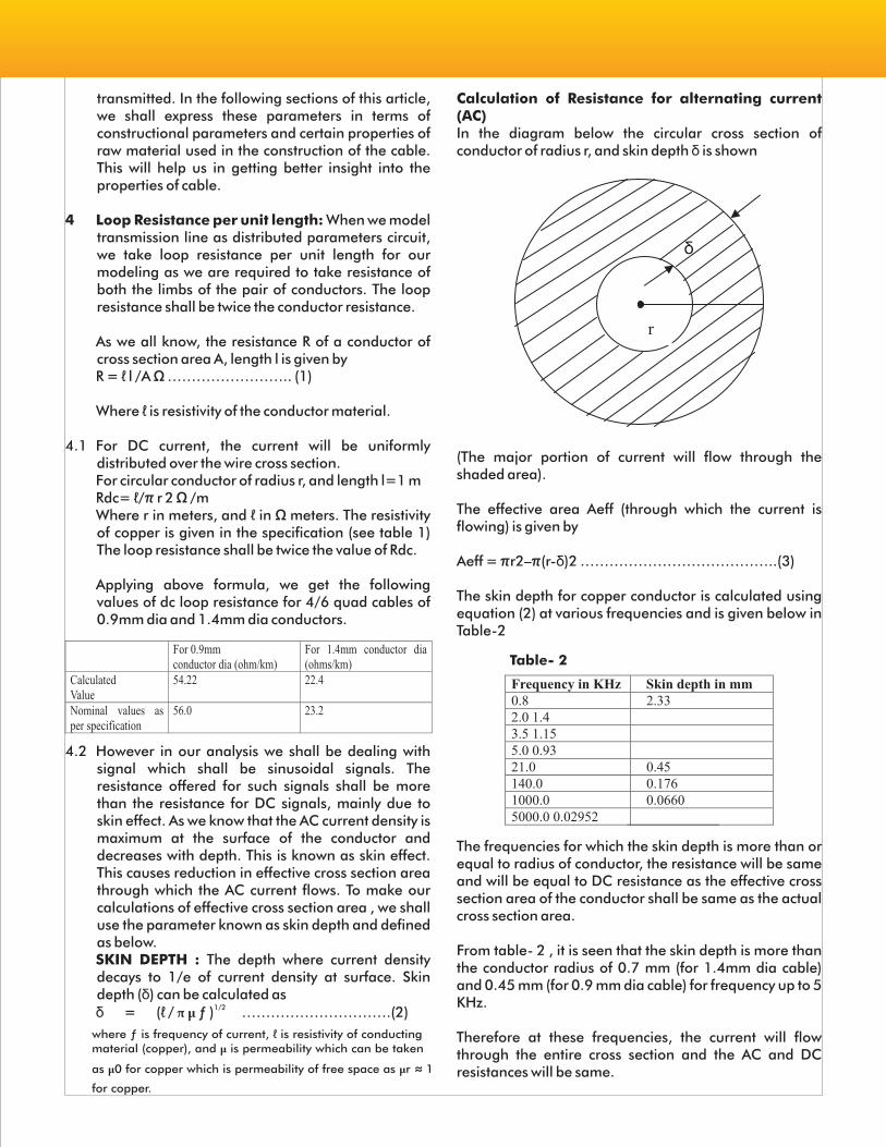
Calculation of Resistance for alternating current (AC)In the diagram below the circular cross section of conductor of radius r, and skin depth δ is shown
r
δ
(The major portion of current will flow through the shaded area).
The effective area Aeff (through which the current is flowing) is given by
Aeff = πr2–π(r-δ)2 …………………………………..(3)
The skin depth for copper conductor is calculated using equation (2) at various frequencies and is given below in Table-2
Table- 2
Frequency in KHz Skin depth in mm 0.8 2.33 2.0 1.4 3.5 1.15 5.0 0.93 21.0 0.45 140.0 0.176 1000.0 0.0660 5000.0 0.02952
The frequencies for which the skin depth is more than or equal to radius of conductor, the resistance will be same and will be equal to DC resistance as the effective cross section area of the conductor shall be same as the actual cross section area.
From table- 2 , it is seen that the skin depth is more than the conductor radius of 0.7 mm (for 1.4mm dia cable) and 0.45 mm (for 0.9 mm dia cable) for frequency up to 5 KHz.
Therefore at these frequencies, the current will flow through the entire cross section and the AC and DC resistances will be same.

At 21 KHz also, the skin depth is equal to conductor radius for 0.9 mm dia 4/6 quad cable.
Based on the above discussion, the resistance is calculated is given below in table-3
Frequency ate lAooppp rroesxiismtance in Ω / km
For 0.9mm Dia cable
For 1.4mm dia cable
For Frequency up to 5KHz (Audio Freq.)
54.22 22.4
at 21 KHz 54.22 25.52
at 140 KHz 86.02 50.86
At 1 MHz 199.5 124.7 At 5 MHz 427.3 271.4
TABLE 3
5.0 Capacitance and inductance as functions of physical parameters of cable.
Application of voltage on the conductor pair will cause flow of current and distribution of charge on wires. This causes setting of transverse electric field as a function of charge and magnetic field as a function of current. For deriving the formula for Inductance per unit length, we need to calculate magnetic flux linkage through the loop formed by per unit length of conductor pair. From the definition of inductance i.e. flux per unit current we arrive at the following formula.L= μ ln(s/r-1) / π Henry/Meter……………………….(4)0
Here μ is permeability of the medium separating the 0
conductor, s is separation between the conductors, r is radius of each conductor and ln is natural log. Similarly for the formula of capacitance, we need relationship between charge and the applied voltage. Distribution of charge on conductors give rise to electric field, which can be used for calculation of potential difference between the conductor of the pair between the two conductor. Using the relation Q= CV, we Derive the following formula.C= π Єo Єr/[ℓn (s/r -1) ] Farad/Meter ………………….(5)
Where Єr is relative permittivity of medium surrounding
the conductor, Єo is permittivity of free space, s is
separation between the conduct, r is radius of conductor. As can be seen, we can reduce the capacitance by reducing the radius of the conductor and by increasing the separation between the conductors. Also by using a material of lower relative permittivity, we can further reduce the conductance.
5.1 Assumption : The following assumption are made in deriving these formula :-
a. The separation between conductors is large enough so that the current/charge in one conductor does not affect the current distribution/charge
distribution in other conductor.b. The medium surrounding the conductors is
homogenous having relative permittivity of Єr.
In our case both of these assumption does not hold, as the conductors are very close to each other and there are not only the second conductor of these pair but other conductors of quad cables also. The medium surrounding is also not homogenous and the media encountered are insulating PE, Petroleum jelly and other conductors of quad which are very nearby.
As the assumption, under which these formula have been derived, do not hold in our case, the calculations will not yield exact values. Still we can have an idea regarding how the physical parameters affect the electrical parameters.
5.2 Calculations of Inductance & CapacitanceThe arrangement of conductor in a quad is shown approximately as below . In this diagram four conductors of a quad are shown. The diagonally opposite conductors are used as pair. In the diagram, d is thickness of the insulation and r radius of the conductors.
2r+2d
d
S
PE insulation of thickness d
r
Copper conductors of radius r
By using simple math we can show that the separations between the diagonally opposite conductors shall be
s= 21/2 (2r + 2d)
Calculation of s for 0.9 mm cable & 1.4 mm cable- Calculated values of s for both type of quad cables are given in table – 4 below.

Table-4 r in mm d (Given in table 1) s=2 1/2 (2r+2d) s/r
0.9 mm cable 0.45 0.35 2.26mm 5.65 1.4 mm cable 0.7 0.6 3.67mm 5.24
Now we make use of equations (4) and (5) to calculate inductance and capacitance for per unit length for both types of quad cables. We will use following values taken from Physicsμ0 = 4 π 10 -7 H/m
Єo = 8.85 x 10 -12 F/m
The conductors are separated by PE insulation and Jelly. The relative permittivity of both is in the range of 2.3 (see table 1). Therefore we will take Єr= 2.3 in our
calculations. We get following values for L and C.
Table-5
L in H/m C in Micro Farad/km
For 0.9 mm cable
55.67 x 10⁻⁸ 0.045
For 1.4 mm cable
57.80 x 10⁻⁸ 0.044
5.3 Discussion on results of calculationThe values of L & C depend on the ratio s/r. The value of C also depends on the relative permittivity of surrounding medium which is quite obvious as in case of a capacitor having its plates separated by dielectric of relative permittivity of Єr. The value of s/r is approximately same
for 0.9mm and 1.4mm cable (see table 4), which explains the same value of capacitance for both types of cables as per their respective specifications.
6.0 Conductance G of pair of quad cableLosses occurring in conductors are represented by resistance of the conductor whereas the losses in surrounding dielectric medium are represented by conductance G.
Two different physical mechanisms contribute to conductivity in dielectrics. These are DC conduction and high frequency dissipation factor. These aredependent on volume resistivity of PE/Jelly and power factor of PE/Jelly.
For most of the practical situation and in our case also for specified values of resistivity of Jelly and PE and power factor (0.0005 at 1 MHz), these losses can be ignored. The conductance due to dissipation factor comes into play at higher frequencies only and is given by G = C x dissipation factor.
ω
Rearranging above, we get
G /ωC = 0.0005 which is very very small compared to 1……………(6)
7.0 Attenuation constant and characteristic impedance.
7.1 Attenuation constant:The sinusoidal wave gets attenuated as it travels down the line. The propagation constant γ is defined as
γ = α+ j β …………………………………………..(7)
= [(R+jωL)(G+ jω C)] 1/2……………...…………(8)
Where α is attenuation constant,And β is phase constant.and, ω is Angular frequency of signalThe velocity of propagation v is given byv = ω/ β m/sFrom equation (7) and (8) we get
1/2α = Real [(R+jωL) (G+jωC) ] and ……………….(9)1/2β = Imaginary [(R+jωl) (G+jωC) ] ………….. (10)
7.2 Characteristic impedance:The characteristic impedance (ZC) is given asZC = [(R+jωL)/(G+ jω C)] 1/2 …………………….(11)
7.3 Approximation for Attenuation constant and characteristic impedance at low frequencies.
We shall make approximations for those frequencies for which R >> ωL. Also as we have seen in equation (6), G << ωC at all frequencies.
Using the assumption R >> ωL , the following is derived from equation (9)
α = 8.686 (RωC) ½ dB/meter ……………………… (12)With the same assumption we shall get characteristic impedance as a complexquantity with magnitude and phase angle whose magnitude shall be given by
1/2Magnitude of ZC = (R/ω C) ohms…………… (13)
7.4 Calculation of losses in audio frequency range
We will now calculate the losses (attenuation constant in dB/km) for both types of cable. We shall use the values of resistance R and C from table 1 (specified value) and value of L form table 5 As we have seen earlier in this article that the skin effect shall not come into play at these frequencies. We get following values for 0.9 mm cable.
Table-6 Frequency Loss in dB/km R/ωL
0.8Khz 0.70 20 2 KHz 1.11 8 3.4 KHz 1.44 4.7 5 Khz 1.75 3.2

Frequencies Loss in dB/km R/ ωL 0.8 kHz 0.45 13 3.4 kHz 0.92 3.0 5 kHz 1.12 2.06
Table 7
For 1.4 mm dia. cable, we get following values
These values are approximate due to
1. We have taken nominal value of C in our calculation 2. The value of R is maximum as per specification 3. R /ωL >> 1 holds good at smaller frequencies. At higher
frequencies. At higher frequencies the error due to this approximation increases.
7.4 Calculation of characteristic impedance in audio frequency range Using equation (13) we get following values
Frequency
For 0.9 mm dia cable For 1.4 mm dia cable 0.8 kHz 472 303 2 kHz 299 192 3.4 kHz 229 147
Table 8
7.5 Approximation for Attenuation constant and characteristic impedance at high frequencies.Now we shall make approximations for those
frequencies for which R << L.
Also as we have seen in equation (6), G << C at all frequencies.
Using the assumption R << L , the following is derived from equation (9)
= 4.343 [(R/ ZC) + (G ZC)] dB/meter ……………… (14)
With the same assumption we shall get characteristic impedance as a real quantity which is given byZC = (L/ C) 1/2 ohms…………………… (15)
For calculation of attenuation as per equation (14) we need to calculate characteristic impedance .
7.6 Calculation of characteristic impedance in high frequency rangeUsing equation (15) we get following values
ωω
ω
α
Table 9 Frequency Value of characteristic impedance in ohms
For 0.9 mm dia cable For 1.4 mm dia cable High frequencies such that R<< ωL
110 ohms approx. 110 ohms approx.
Table 10 : Losses for 0.9 mm dia cable
Frequency Loop resistance R in ohms/km taking skin effect into account (See table 3)
Value of ωL/R to check our assumption ωL>>R
G in mhos /km (Using equation 6).
Loss in dB/km
21 kHz 56 1.31 0.000003297 2.21 140 kHz 86.2 5.69 0.00002198 3.40 1 MHz 199.5 17.52 0.000157 7.95 5 MHz 427.3 40.91 0.000785 17.24
7.7 Calculation of losses at high frequenciesWe will use equation (11) for calculation of loss at high frequencies. At high frequencies, characteristic impedance approaches an approximate value of 110 Ohms. The value of R will depend on frequency due to skin effect. Also, the value of G as given by equation (6), varies linearly with frequency. The calculation of loss is given below in table 10 and table 11 below .
7.8 Discussion on results obtained for losses.As we have divided our discussion on losses in two groups of frequencies. At lower frequencies we assumed R to be dominant as compared to ωL. At higher frequencies, ωL was assumed to be dominant factor as compared to R. However these assumptions are off the mark for a particular frequency range. This frequency ranges is from 3.4 KHz to 21 kHz for 1.4 mm quad cable. For 0.9 mm quad cable such frequency range is from 5 kHz to 21 KHZ. Therefore in this range , more error shall be there if we use the approximate formulae. Also the results obtained are at variance with those mentioned in specification. The values specified in specification are for worst case as they define the limit on the parameters. Also while deriving formulae for Capacitance and inductance, we made certain assumptions as mentioned in para 5.1.
8.0 Conclusion: In this article we related the per unit length parameters required for modeling of the transmission line, to the constructional features of the quad cable and the properties of raw material used in the construction of quad cable. Then we applied well known formulae of transmission lines for calculation of loss and characteristic impedances for quad cable. These calculations were done in voice frequency band and at high frequencies. At these frequencies, we could simplify the formulae to help us understand the behavior of the cables at these frequencies and relate it to the physical features of the cable.
References1 RDSO Specification No. IRS:TC/30/2005 for
“Underground Jelly Filled Quad Cables for Signaling and Telecom installations”.
2 RDSO Specification No. RDSO/SPN/TC/30/2005 for “1.4 mm dia. Copper conductor 4/6 quad cable”.
3 Clayton, R. Paul.: Introduction to Electromagnetic compatibility, 2nd Edition.John Wiley and Sons Publication.
Table 11 : Losses for 1.4 mm dia cable
Frequency Loop resistance R in ohms/km taking skin effect into account (See table 3)
Value of ωL/R to check our assumption ωL>>R
G in mhos /km (Using equation 6).
Loss in dB/km
21 kHz 25.52 2.88 0.000003297 1.01 140 kHz 50.86 9.62 0.00002198 2.01 1 MHz 124.7 28.03 0.000157 4.99 5 MHz 271.4 64.41 0.000785 11.09
Multilevel Railway Traffic Interval Controland Safety System (MICSS)Research and Development Institute for Railway AutomaticsMoscow Russia
4. MICSS COMPONENT PARTS
4.1 Unified Integrated Locomotive Safety System (UILSS)
4.1.2 UILSS Structure (Block-diagram, Composition. Purpose of the units)
UILSS is designed for locomotives and motor car rolling stock (MCRS) operating with diesel and A.C./D.C. electric traction.UILSS systems ensure railway traffic safety by preventing emergency situations through forced train braking or stop.
UILSS functions :- reception of data signals from Automatic
Locomotive Signalling (ALS) track devices, as well as from radio network whether the ahead track section is free or occupied, as well as traffic light signals, location of the ahead train, route and temporary speed limits;
- train (locomotive) positioning;- determining train speed and current time;- determining the train speed limit by signals from
ALS track devices and the radio channel, as well as depending on the train location (co-ordinates) and local speed limits;
- indication to the locomotive driver of signals from ALS track devices, train travel parameters and data generated by the system;
- monitoring of train speed and forced braking or train stop if the speed limit is exceeded;
- prevention of passing onto stop traffic light signals;- prevention of an unauthorised locomotive start
(rolling down);- prevention of locomotive travel with the safety
system switched off;- locomotive driver's vigilance control by his
response to a light or audio signal, or by monitoring physiological parameters with a special device;
- recording of train travel parameters and UILSS signals in a removable cassette.
UILSS consists of :- Locomotive Electronic Unit (EU-U), one per
locomotive or a motor car unit;- Unified Locomotive Parameters Input and Indicated
Unit (LIIU-U), one per locomotive cab or a motor car unit;
- Unified Switching Unit (SU-U), one per locomotive;
- Locomotive Power Supply (LPS), one per locomotive or a motor car unit;
- Transceiver for Digital Radio Communication (XCVR);
- Reception Coils of the rails communication channel (RC);
- Satellite Navigation Antenna (SNA);- Radio Channel Antenna (RChA);- Distance and Speed Meter (DSM), two for one
UILSS;- Electro-Pneumatic Valve for Emergency Braking
(EPV), (one for a cab);- Pressure Transducers (PT), four per one motor car
unit or six per one single-body locomotive;- Unauthorised Switching-Off Control Unit (USC);- Cables Set (one per locomotive);
Besides, the following units are supplied for a locomotive depot :- Input and Testing Unit (ITU-U);- Parameters Control Console (CC-UILSS);- Decoder of the Recorded Parameters (DU), one per
one decoding workstation at a depot.
The major UILSS units are locomotive electronic unit (EU-U), input and indication unit (LIIU-U) switching unit (SU-U).
EU-U is designed for :- reception of signals from reception coils VRC-1
(Versatile Reception Coils), one-point communication channel antennas, radio transceiver, SNS antennas, distance and speed meters, pressure transducers, locomotive circuits, LIIU-U controls and buttons, DVC (Driver Vigilance Control) sytems;
- processing of real time data;- transfer of data to LIIU-U for indication and
recording, as well as for operating the EPV.
LIIU-U ensures :- indication of ALS (Automatic Locomotive
Signalling) signals;- indication of train travel parameters (co-ordinates,
speed) based on the data from EU-U;- indication of current time;- indication of the target speed and speed limit;- generation of the <<Attention>> light signal;- audio signalling when LIIU-U data changes, except
for the co-ordicate, time and actual speed, pressure in the braking pipe-line and brake cylinders, as well as when keyboard buttons are pressed, VB (Vigilance Button) and VBS (Vigilance
Locomotive Electronic Unit (EU-U)
Input and Indication Unit (LIIU-U)
(Continued....)

Button Special) buttons are pressed and released;- input and indication of locomotive and train
parameters;- indication of the operation mode, recording
cassette availability, as well as input and test data;- recording of train travel current data, locomotive
and train parameters from EU-U.
LIIU-U overall dimensions are 25 (width) x 345 (height) x 140 (depth) mm.
The LIIU-U reliability under operating conditions has the following parameters :- mean time between failures (MTBF) - 40,000 hours
and more;- service life-15 years and more;- mean recovery time- one hour and less.
SU-U is designed to process signals from pressure transducers and connect peripheral devices to EU-U.
SU-U is manufactured in two versions specified below in Table 1.
Table 1.Version Code LocationSU-U-2 Single-unit locomotive with two cabsSU-U-1 Two-unit locomotive with one cab in
each unit or MCRS
SU-U-1 is designed to :- connect UILSS units and devices;- generate data for recording;- supply power to UILSS units and devices.
SU-U-2 is designed to:- connect and switch UILSS units and devices
according to the locomotive cab option;- generate data for recording;- supply power to UILSS units and devices.
EU-U is designed for:- reception of signals from reception coils VRC-1
(Versatile Reception Coils), one-point communication channel antennas, radio transceiver, SNS antennas, distance and speed meters, pressure transducers, locomotive circuits, LIIU-U controls and buttons, DVC (Driver Vigilance Control) system;
- procesing of real time data;- transfer of data to LIIU-U for indication and
recording, as well as for operating the EPV.
LIIU-U ensures :- indication of ALS (Automatic Locomotive Signalling)
signals;- indication of train travel parameters (co-ordinates,
Switching Unit (SU-U)
Locomotive Electronic Unit (EU-U)
Input and Indication Unit (LIIU-U)
speed) based on the data from EU-U.- indication of current time;- indication of the target speed and speed limit;- generation of the <<Attention>> light signal;- audio signalling when LIIU-U data changes, except
for the co-ordinate, time and actual speed, pressure in the braking pipe-line and brake cylinders, as well as when keyboard buttons are pressed, VB (Vigilance Button) and VBS (Vigilance Button Special) buttons are pressed and released;
- input and indication of locomotive and train parameters;
- indication of the operation mode, recording cassette availability, as well as input and test data;
- recording of train travel current data, locomotive and train parameters from EU-U.
LIIU-U overall dimensions are : 256 (width) x 345 (height) x 140 (depth) mm.
The LIIU-U reliability under operating conditions has the following parameters :- mean time between failures (MTBF) - 40000 hours
and more;- service life-15 years and more;- mean recovery time- one hour and less.
SU-U is designed to process signals from pressure transducers and connect peripheral devices to EU-U.
SU-U is manufactured in two versions specified below in Table 1.
Version Code LocationSU-U-2 Single-unit locomotive with two cabsSU-U-1 Two-unit locomotive with one cab in
each unit or MCRS
SU-U-1 is designed to:- connect UILSS units and devices;- generate data for recording;- supply power to UILSS units and devices.
SU-U-2 is designed to:- connect and switch UILSS units and devices
according to the locomotive cab option;- generate data for recording;- supply power to UILSS units and devices.
SU-U-1 and SU-U-2 are powered from the 48+-3V, D.C. power source with peak-to-peak amplitude of 3V and less.
For effective UILSS operation the following units are used at a locomotive depot:- the automatic Decoder of the recorded data (DU)- pre-trip testing devices.
Switching Unit (SU-U)

The automatic Decoding Units (DU) is designed for the data recorded to the electronic memory of the removable cassette which is used for the analysis of the locomotive team work adn serviceability of the locomotive equipment.
The input and testing unit (ITU-U) performs pre-trip of the equipment and reinstallation of the electronic map.
The locomotive input unit (LIU-U) (part of LIIU-U) is used for inputting the pre-trip data and the UILSS operation mode control.
Pressure in the braking pipe-line is measured with pressure transducers.
Reception coils, a turning angle sensor (TAS) and an electro-pneumatic valve (EPV) are part of UILSS as well.
The satellite navigation antenna (SNA) is designed for receiving signals from the satellite navigation systems GPS and GLONASS. The antenna is installed on roof of the locomotive cab.
Power supplies are designed to energise the locomotive electronics with D.C. voltage of 50 +-5 V isolated from primary voltages which can be 50 or 110V. LPS can be used for various types of rolling stock such as locomotives, D.C./A.C. electric trains, diesel locomotives, railway motor cars.
LPS output power does not exceed 300W. LPS input voltage must not exceed 57V, loading being changed from the highest to idle.
LPS output voltage fluctuations under conditions of the loading being changed in the 0 to 100 KHz frequency brand must not exceed 3V of the peak value.
To ensure data exchange over the radio channel UILSS applies the IR24SV-22 "Most-M1" radio.
XCVR Technical Characteristics :
Frequency band 450-460 MHzCarrier frequency selection by frequency sythesiserFrequency spacing 25 kHzChannels 15 programmable channelsOperating mode simplex, half duplexData transmission rate 9600 bits/secFormat asynchoronous-8 data bits
without parity, 1 stop bit
Locomotive Power Supply Units (LPS)
Transceiver (XCVR)
General Characteristics
Delay in transmission to less than 22 msthe radio channelDelay in reception from less than 2,5 msthe radio channelDelay of the radio less than 19 msavailability after transmissionInterface voltage level RS-232 standardProtocol two-wire, RS-232 standard
CTS high at switch-onRated power supply 48±7V with peak-to-peak
value not more than 3V13V±1V fixed voltage (at station)
Power consumption, less than 1A (in locomotive)transmissionOperating temperature -30..+60 degrees Crange
Receiver Characteristics-6Frequency stability ±1,5x10
Sensitivity -12 dB SINAD at ≤ 0,5 micro V
Slectivity -70dB
Transmitter Characteristics-6Frequency stability ±1,5x10
Max. deviation 5 kHzModulation direct control FMOutput power 5W at rated power supplyOn-off time ratio more than 2transmissionContinuous radiation less than 30sExtraneous radiation less than 70 dB
The locomotive reception coil (VRC) ensures inductive coupling between the receiver and electric track circuits and is designed to receive ALS coded signals.
VRCs are manufactured in two design version:VRC-1 single VRC,VRC-2-twin VRC
VRC-1 is designed for joint operation with one ALS receiverVRC-2 is designed for joint operation with two isolated ALS receivers.
The main technical characteristics of VRC reception coils are specified the Table below :Emf induced in the windings of a coil suspended at the height of 150 mm from the upper face of the rail head to the lower coil face is not less than the values specified in the table below :
Reception Coils

IRSTE (India) Activities on Indian Railways2013-14 - April-June 2013 progress
In the last quarter, a few Railways have carried out some activities under their IRSTE chapter to meet the objective of spreading the science of Railway Signalling & Telecom. Details are as under :
1. RDSO CHAPTER, Lucknow
Lucknow chapter organized a seminar on 28th May, 2013 at RDSO Lucknow. President of IRSTE Lucknow chapter and Sr. ED Signal, Shri Mahesh Mangal graced the occasion. The seminar was attended by about 26 officers and staff of various directorates of RDSO. On this occasion the following presentations were made.
1. Data network Securityby Shri Deepinder SinghSystem Engineer,Cisco System (India)
2. Next generation packet Transport network for Signalling and Telecom applicationsby Shri Binu NairSr. Technical ConsultantCisco System (India)
The first paper covered general idea about Security threats like worms and viruses. Overtime, threats evolved to spyware and rootkits and became harder to find and to detect. Now, advanced persistent threats and cyberware are the big proble. Entire nation states are involved, meaning it's not just enterprises being impacted, but entire governments. Now, there is an increased attack surface emerging. "What's Old is New Again. "Nation see the reemergence of DDoS. As clouds take over business, one of the ways to disrupt the cloud is through DDoS attacking. One is seeing the threat landscape evolve and using multiple ways of coming at the enterprise and government. Therefore, all are evolving our strategy to deal with these issues.
This new multi-dimensional problem required a new approach to security, all need to shift from piecemeal security approach to architecture-based approach. Security Architecture starts with the network as the platform for policy, and security as a single set of services that can integrate across the Data Center, routers, switches etc. and that's brought together by a common layer of management, policy and context awareness. Attacks are more sophisticated, attackers better funded and much smarter than they were in the past. For
and much smarter than they were in the past. For example, hackers are using masking technologies and even SSL encryption.
Security products are powered by Security Intelligence Operations which gather analyzes vast amounts of global data and application traffic so it is able to provide real time threat landscape information. Critical information is pushed down to security devices every three to five minutes. Cisco's ability to push global threat intelligence into the security architecture allows devices to make decisions based on a combination of both real threat information and context.
2. Chennai Chapter of Southern Railway :
IRSTE (India) organised "International World Telecom Day on 17th May, 2013.
On the World Telecom Day celebrations, Shri Rakesh Misra, General Manager, S. Rly was the Chief Guest, Dr. G. Narayanan, Addl. General Manager, S. Rly and other Senior Officers participated in the inaugural funciton of the World Telecom Day Celebrations.
During the Inauguration function, General Manager released the Compendium on Telecom issues and JA Grade Telephone Directory/Southern Railway
Following Technical papers were presented during the IRSTE Seminar.
1. Train Protection & Warning System (TPWS) by M/s ANSALDO.
2. Video Conferencing System by Akio Yamani of Panasonic / Japan.
3. Planet Earthing by Mr. K. Kasairajan, SNM/FOIS.4. ABS INDIA ALCATEL-LUCENT Enterpr ise
Communications Enabling Enterprises presentation by Dr. S. Vinaya (ABS India)
5. Presentation by IET6. Mobile Video Conferencing by Shri Muthukumaran
from Polycom.7. Video Walls for Control Communications & other
Applications by Shri Rajan Vashist, Director/Sales M/s Delta India Electronics, New Delhi.
8. RailTel as Technology partner in Development in Rural India by Shri S. Selvadurai & Shri N. Janakiraman M/s RCIL
9. Need for Network Security Layers in Indian Railway by Shri Rajesh Rajnendran from Cyberoam.
10. Wireless Technology for large campuses by Shri Panneer Selvam, from Ruckus Wireless.
Hope that in the current quarter, we may see many such papers and events on each of the railway.

Photo Gallery