is 10122 (1982): methods of tests for crucible induction ... · is : 10122 - 1982 indian standard...
TRANSCRIPT

Disclosure to Promote the Right To Information
Whereas the Parliament of India has set out to provide a practical regime of right to information for citizens to secure access to information under the control of public authorities, in order to promote transparency and accountability in the working of every public authority, and whereas the attached publication of the Bureau of Indian Standards is of particular interest to the public, particularly disadvantaged communities and those engaged in the pursuit of education and knowledge, the attached public safety standard is made available to promote the timely dissemination of this information in an accurate manner to the public.
इंटरनेट मानक
“!ान $ एक न' भारत का +नम-ण”Satyanarayan Gangaram Pitroda
“Invent a New India Using Knowledge”
“प0रा1 को छोड न' 5 तरफ”Jawaharlal Nehru
“Step Out From the Old to the New”
“जान1 का अ+धकार, जी1 का अ+धकार”Mazdoor Kisan Shakti Sangathan
“The Right to Information, The Right to Live”
“!ान एक ऐसा खजाना > जो कभी च0राया नहB जा सकता है”Bhartṛhari—Nītiśatakam
“Knowledge is such a treasure which cannot be stolen”
“Invent a New India Using Knowledge”
है”ह”ह
IS 10122 (1982): Methods of tests for crucible inductionfurnaces [ETD 17: Industrial Electroheating Equipment]


IS : 10122 - 1982
Indian Standard
METHODS OF TESTS FOR CRUCIBLE INDUCTION FURNACES
Industrial Elecro-heating Equipment Sectional Committee, ETDC 61
Chairman Representing
SHRI S. K. MAZUMDER Tata Iron and Steel Co Ltd, Jamshedpur
Members
SHRI A. K. BISWAS ( Alternate to Shri S. K. Mazumder )
SHRI G. A. ADVANI Westerwork Projects Ltd, Bombay SHRI L. C. CHANDI ( Alternate )
SHRI S. N. AGARWAL Steel Furnace Association of India, New Delhi SHRI S. K. BHATTACHARJI M. N. Dastur & Company (P) Ltd, Calcutta
SHRI T. K. GHOSH ( Alternate ) SHRI R. M. CHANDWANI Hindustan Brown Boveri Ltd, Vadodara
SHRI P. S. SHARMA ( Alternate ) SHRI KAUSHAL GOEL Engineering Projects ( India) Ltd, New Delhi
SHRI M. M. PRASAD ( Alternate ) SHRI S. S. HUBLI Kirlo;g;reElectric Co Pvt Ltd ( Unit IV ),
SHRI S. S. HEMACHANDER ( Alternate ) SHRI A. K. JAIN Graphite India Ltd, Calcutta
SHRI J. K. AGARWAL ( Alternate ) SHRI G. L. KESWANI Directorate General of Technical Development,
New Delhi SHRI A. K. KESAVALU ( Alternate )
SHRI 0. N. KRISHNAN Metallurgical & Engineering Consultants ( India ) Ltd, Ranchi
SHRI J. C. MADAN Steel Authority of India Ltd, New Delhi SHRI A. K. JAIN ( Alternate )
SHRI P. K. MUKHOPADHYAY Heavy Machine Building Plant, Heavy Engineering
SHRI M. K. NAIR
SHRI P. A. PATEL
Corporation, Ranchi Directorate General of Ordnance Factories
( Ministry of Defence ), Calcutta Indian Furnace Company Ltd, Bombay
SHRI M. PURANDHAR ( Alternate ) SHRI V. R. K. N. SASTRI Mishra Dhatu Nigam Ltd, Hyderabad
SHRI N. RAGHAVAN ( Afternate )
( Continued on page 2 )
@I Copyright 1982
INDIAN STANDARDS INSTITUTION This publication is protected under the Indian Copyright Act ( XIV of 1957 ) and reproduction in whole or in part by any means except with written permission of the publisher shall be deemed to be an infringement of copyright under the said Act.

IS : 10122 - 1982
(Continued from page 1 )
Members Representing
SwuS. V. KRISHNA RAO Rharat Heavy Electricals Ltd, Secunderabad SHRI B. PATHIRAJ ( Alternute )
SHRI M. SHANKRAIJNGAM Directorate General of Supplies & Disposals, New Delhi
SHRI R. V. NARAYANAN ( Alternate ) SHRI Y. P. VATSA The General Electric Co of India Ltd, Calcutta
Swnr S. M. BANERJEE ( Alternare ) SHRI S. P. SACHDEV, Director General, ISI ( Ex-officio Member )
Director ( Elec tech )
Secretary
SHRI Jose MATHEW
Assistant Director ( Elec tech ), IS1
2

IS : 10122 - 1982
Indian Standard METHODS OF TESTS FOR
CRUCIBLE INDUCTION FURNACES
0. FOREWORD
0.1 This Indian Standard was adopted by the Indian Standards Institution on 8 February 1982, after the draft finalized by the Industrial Electro- heating Equipment Sectional Committee had been approved by the Electro- technical Division Council.
0.2 This standard lays down the test methods to determine the essential parameters and technical characteristics of electroheating installations comprising crucible induction furnaces.
0.3 In preparing this standard, assistance has been derived from IEC Publication 646 ( 1979 ) ‘Test methods for crucible induction furnaces’ issued by International Electrotechnical Commission.
0.4 In reporting the result of a test or analysis made in accordance with this standard, if the final value, observed or calculated, is to be rounded off, it shall be done in accordance with IS : 2-1960*.
1. SCOPE
1.1 This standard applies to electro-heating installations comprising indus- trial coreless ( crucible ) induction furnaces for melting and for holding a molten charge.
2. TERMINOLOGY
2.0 For the purpose of this standard, the following definitions in addition to those given in IS : 1885 ( Part LI/Sec 1 )-19797 shall apply.
2.1 Electroheating Installation with Coreless ( Crucible ) Indoction Furnace- Installation comprising the coreless ( crucible) induction furnace and the electrical and mechanical equipment necessary for the operation and utiliza- tion of the furnace.
The electrical installation comprises all electrical components including conductors and switchgear in the power control, and regulation circuits, situated after the main circuit-breaker ( see Fig. 1 ).
*Rules for rounding off numerical values ( revised ). tElecrotechnica1 vocabulary: Part LI Industrial electroheating, Section 1 Geqeral
terms.
3

IS : 10122 - 1982
2.2 Compensated Circuit of the Furnace - The electrical circuit comprising the inductor and its compensating capacitor bank.
2.3 Power of an Electroheating Installation ( Apparent Power S,, or Active Power P, ) -The electrical power calculated or measured at the input of the supply line, all the electrical parameters being at rated values. The apparent power S, is calculated in kVA. The active power P,, is measured in kW.
2.4 Power Factor of an Electroheating Installation - The ratio of the active power to the apparent power, measured at the input of the supply line.
2.5 Holding Power of au Electroheating Installation Pm - Active power ( P,,, expressed in kW ) consumed by the installation, in order to maintain the rated charge at the rated temperature.
2.6 Specific Energy Consumption ( kWh/kg ) - Ratio of the total amount of electrical energy ( kWh ) consumed by an electroheating installation for heating, melting and possibility of superheating the charge to the weight of the rated charge ( kg ).
2.7 Melting Rate of the Furnace of an Electroheating Installation (kg/h )- Ratio of weight of the charge ( kg ) brought to its final temperature to the total time ( II ) necessary for heating, melting and possibly superheating of the charge.
2.8 Rated Values of an Electroheating Installation -The rated values of the installation are those for which it is designed and marked; the marking shall comprise the following:
a) frequency& ( Hz ),
b) voltage U,, ( V),
c) supply ( single or three-phase ),
d) active power P,, (kW ), and
e) apparent power S,, ( kVA ).
2.9 Coreless ( Crucible ) Induction Furnace - Melting or holding furnace, without closed magnetic circuit, in which the heat is generated, directly in the charge or in the crucible containing it, by an inductor disposed around the crucible.
2.10 Crucible -Receptacle containing the charge and made of refractory or conducting material.
2.11 Induction Coil-Induction coil ( intended to be connected to a supply of low or medium frequency ) creating the magnetic field, which generates induced currents in the metal charge or in the crucible of conductive materials.
4

IS : 10122 - 1982
2.12 Coil Supporting Framework -Holding assembly for the induction coils, to prevent the heating of the surrounding construction.
2.13 Rated Capacity of Furnace (in ms )-Volume of the specified nominal molten charge which the furnace may contain with the specified crucible dimensions under normal operating conditions and at rated power.
2.14 Rated Charge ( in kg ) - Weight of molten specified charge correspon- ding to the rated capacity.
2.15 Voltage of the ‘Compensated Circuit of the Furnace U, (V ) - Voltage across the terminals of the input of the compensated circuit of the furnace.
2.15.1 Furnace Voltage up ( V ) - Voltage across the terminals of the induction coil or system of induction coils.
2.16 Furnace Current IF ( A ) - Current in the induction coil or the system of induction coils of a furnace at rated voltage.
2.17 Furnace Frequency fF (Hz) - Frequency applied to the terminals of the furnace induction coils or the system of induction coils.
2.18 Charge Temperature tJ ( “C ) - The temperature of the material repre- senting the charge at a given moment.
2.19 Final Charge Temperature &,F ( “C! ) - The temperature which the charge should reach immediately before tapping.
2.20 Inlet Temperature of Coolant flFi ( “C ) -Temperature of coolant when entering the cooling circuit of the furnace.
2.21 Outlet Temperature of Coolant flFO ( “C ) - Temperature of coolant when leaving the cooling circuit of furnace operating under rated conditions.
2.22 Ambient Temperature On ( “C) - Air temperature outside the furnace at a point sufficiently remote so that heat radiation or natural convection exert no influence.
2.23 Furnace Duty in Rated Conditions ( Rated Furnace Duty ) - Furnace operation at the rated values ( voltage, frequency, power and rated capacity ).
2.24 Hot State of Furnace - State of a furnace after the charge attains the final temperature in the thermal steady-state of the furnace.
2.25 Thermal Steady-State of a Furnace-Thermal state in which the whole energy input into the furnace is used for the compensation of thermal losses.
5

IS : 10122 - 1982
2.26 Cold State of Furnace -Thermal state in which the temperature of the furnace constructional component parts is equal to the ambient temperature.
2.27 Intermittent ( Batch) Operation of a Furnace - Operation in which a new melting cycle is started only after the tapping of the preceding charge.
2.28 Continoons Operation of a Furnace - Operation during which the molten charge is continually withdrawn, and charge is continually added.
2.29 Power of the Compensated Circuit -Electric power ( apparent S, in kVA or active P, in kW) of the charged furnace, at the input of the compensated circuit.
2.29.1 Furnace Power - Electric power ( apparent SF in kVA or active PF in kW ) of the charged furnace at the terminals of the induction coil or system of induction coils.
2.30 Power Factor of Compensated Circuit - Ratio of the active power to the apparent power of the furnace, at the input to the compensated circuit.
2.30.1 Power Factor of Furnace Inductor - Ratio of active power to the apparent power of the furnace, at the terminal of the induction coil or system of induction coils.
3. TESTS
3.0 General Conditions for Performance of Tests -The general conditions for performing tests shall be in accordance with IS: 9021-1978*.
3.1 List of Tests -For the assessment of an electroheating installation containing crucible induction furnace, the following tests shall be performed in the order given below:
a> b) cl d)
e>
f>
8)
Electrical withstand test of induction coils ( see 3.2 );
Pressure test of water-cooled induction coils ( see 3.3 );
Flow test of water-cooled induction coils ( see 3.4 );
Measurement of power and power factor of the electroheating installation ( see 3.5 );
Determination of holding power of the electroheating installation ( see 3.6 );
Determination of specific energy consumption and melting rate of the electroheating installation ( see 3.7 );
Measurement of temperature-rise of the coolant ( see 3.8 );
*Specification for general test conditions for industrial electro-heating equipment.
6

IS : 10122 - 1982
h) Measurement of temperature of the furnace constructional elements ( see 3.9 ); and
j) Measurement of temperature of charge ( see 3.10 ).
3.2 Electrical Withstand Test of Induction Coils-This test shall be per- formed at mains frequency with a substantially sine wave voltage of 2 U, + 1000 V ( with a minimum of 2 000 V ) where U, is the rated voltage of the inductor. The voltage shall be applied between components which are live when the furnace is in normal operation and all metal parts accessible to touch are connected together and earthed. It shall be raised progressively within 10 seconds to its test value which should be maintained for one minute.
The electrical withstand test for water-cooled furnaces is performed before the refractory lining is fitted and with the cooling water duct disconnected so that the components which are normally live during service of the furnace are not connected electrically to the metal housing of the furnace via the water.
No breakdown or Aashover of the insulation shall occur during these tests.
3.3 Pressure Test of Water-Cooled Induction Coils - The test is to verify the integrity of the cooling water circuits. After closing the outlet of water circuits, the water pressure is raised to 150 percent of the pressure specified by the furnace manufacturer. This pressure is maintained for at least 5 minutes. No water leakages should occur during these tests.
3.4 Flow Test of Induction Coils -The test is to verify by means of an appropriate method that the cooling circuits of the coils will carry the specified flow without exceeding a specified pressure drop.
3.5 Measurements of Power and Power Factor of an Electroheating Installation - The measurement of active power, shall be made by means of appropriate measuring instruments. The apparent power can be detemined from the measurement of the current and voltage. The measure- ments shall be carried out at rated duty and at the hot state of the furnace. The power factor can be calculated as the ratio of the active power and the apparent power.
The accuracy class of the measuring instruments should be < 1.5.
NOTE - The content of voltage and current harmonics when sufficiently reduced does not affect the test result; in these conditions the power factor defined in 2.4 becomes practically equal to the cos 4 measured by means of a cos 4 meter. In the case of a three-phase supply, it should be ensured that during those measurements currents in the three phases show no significant unbalance. It could be considered as a guide line that this requirement is met when the deviation of the current values from their mean value does not exceed f 10 percent. Where the out-of-balance of the three-phase line exceed i 10 percent, an appropriate and more accurate method must be employed.
7

IS : 10122 - 1982
3.6 Determination of Holding Power of an Elcetroheating Installation - The furnace, containing the rated charge, shall have been in normal operation for a sufficient time to ensure that it is in a hot state ( see 2.24 ). Throughout the test period, the final temperature of the charge shall be maintained as constant as practical. In addition to the temperature of the charge, the energy consumption of the furnace and the holding time are measured. The energy shall be measured at the input with an electrical energy meter. The holding power shall be calculated by dividing the energy by the time.
The accuracy class of the measuring instruments shall be < l-5.
3.7 Determination of Specific Energy Consumption and Melting Rate of the Electroheating Installation - The measurement shall be started after the furnace has been in operation for a sufficient time to ensure that it is in the hot state.
3.7.1 The test shall be started immediately after a charge of the size of the test charge has been tapped from the furnace containing its rated charge. If the test charge is less than rated charge, the remaining charge shall be at the final temperature. In any case charging should be started immediately after tapping or after the remaining charge is heated up to its final temperature.
3.7.2 During the operation of the furnace, the electrical energy consumed shall be measured by means of an electrical energy meter, connected at the input of the installation. Also, the time during which the furnace is switched on ( that is, the time of heating of the charge ), as well as the charge temperature, shall be measured at the beginning of the charge and before tapping, in order to prevent excessive overheating of the charge which should be tapped immediately after reaching its final temperature. When the melting and eventual superheating are completed, the test charge shall be tapped, and at least three more successive melts shall be carried out in the same manner.
3.7.3 The specific energy consumption shall be calculated by dividing the energy consumed during the described measuring cycle (subtracting the time the furnace has been out of operation ) by the weight of the charge furnished by the. furnace during this time. The value to be adopted is the arithmetic mean of the specific energy consumption values from the tests.
The melting rate of the furnace is calculated by dividing the weight of the charge furnished by the furnace during the measuring cycle described above, by the duration of this cycle. The value to be adopted is the arithmetic mean of melting rate values determined during tests.
NOTE - Thermal losses due to opening of lids and power-off-times during the tests may strongly influence the results during the test. They should be kept at minimum and must be taken into consideration for evaluating the results.
8

IS : 10122 - 1982
3.8 Measurement of Temperature-rise of the Coolant - This test shall be carried out in the hot state of the furnace ( see 2.24 ) operating under rated conditions ( see 2.23) at the end of the test in 3.7. The temperature shall be measured by thermometers or equivalent devices placed at the inlet and outlet of the circuit, readings being taken every 5 minutes over at least a 30 minutes period. The difference between the average temperature values read at the inlet and outlet will give the temperature-rise value.
3.9 Measurement of Temperature of Furnace Constructional Components- This test shall be carried out directly after the test in 3.7. The temperature at different points of the external surfaces of the walls of the furnace housing shall be by means of a contact thermocouple, thermometer, or equivalent device.
3.10 Measurement of Temperature of the Charge - This measurement shall be carried out by means of a thermocouple. The instrument used shall have a measuring accuracy of at least f15”C within the range from 300 to 1000°C and of f20”C above 1 000°C. Care should be taken to ensure that the measuring element is properly inserted in the molten metal.
9
I
IS : 10122 - 1982
LINE
j I co5 ‘P” co3 ‘PC - ELECTROHEATING
INSTALLATION
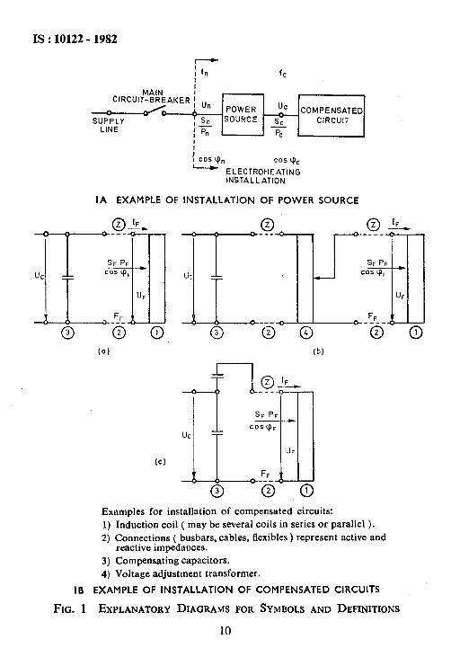
IA EXAMPLE OF INSTALLATION OF POWER SOURCE
(a) (b)
Examples for installation of compensated circuits: 1) Induction coil ( may be several coils in series or parallel ). 2) Connections ( busbars, cables, Elexibles ) represent active and
reactive impedances. 3) Compensating capacitors. 4) Voltage adjustment transformer.
IB EXAMPLE OF INSTALLATION OF COMPENSATED CIRCUITS
FIG. 1 EXPLANATORY DIAGRAMS FOR SYMBOLS AND DEFINITIONS
10
