is 11401-2 (1990): general requirements for slow sand
TRANSCRIPT

Disclosure to Promote the Right To Information
Whereas the Parliament of India has set out to provide a practical regime of right to information for citizens to secure access to information under the control of public authorities, in order to promote transparency and accountability in the working of every public authority, and whereas the attached publication of the Bureau of Indian Standards is of particular interest to the public, particularly disadvantaged communities and those engaged in the pursuit of education and knowledge, the attached public safety standard is made available to promote the timely dissemination of this information in an accurate manner to the public.
इंटरनेट मानक
“!ान $ एक न' भारत का +नम-ण”Satyanarayan Gangaram Pitroda
“Invent a New India Using Knowledge”
“प0रा1 को छोड न' 5 तरफ”Jawaharlal Nehru
“Step Out From the Old to the New”
“जान1 का अ+धकार, जी1 का अ+धकार”Mazdoor Kisan Shakti Sangathan
“The Right to Information, The Right to Live”
“!ान एक ऐसा खजाना > जो कभी च0राया नहB जा सकता है”Bhartṛhari—Nītiśatakam
“Knowledge is such a treasure which cannot be stolen”
“Invent a New India Using Knowledge”
है”ह”ह
IS 11401-2 (1990): General requirements for slow sandfilters, Part 2: Design, construction, operation andmaintenance [CED 24: Public Health Engineering.]


IS 11401(Part2) :1990
Indian Standard
GENERiiLREQUIREMENTSFOR -.
l . SLOWSANDFILTERS I I \ .a' PART 2 DESIGN, CONSTRUCTION, OPERATION AND MAINTENANCE
UDC 628’16’067’1
a-. . ’ I \
. _’
\ 4’ \ 1 ’ . -’ @I BIS 1990
BUREAU OF INDIAN STANDARDS MANAK BHAVAN, 9 BAHADUR SHAH ZAFAR MARG
NEW DELHI 110002
OctabGT 1990 Price Croup 3

Public Health Engineering Equipment Sectional Committee, CED 40
FOREWORD
This Indian Standard was adopted by the Bureau of Indian Standards on 24 January 1990, after the draft finalized by the Public Health Engineering Equipment Sectional Committee had been approved by the Civil Engineering Division Council.
A safe and convenient water supply is paramount importance to human health and well being of a society as a whole. Although the field of water treatment offers a variety of technological choices, only a few of them fully meet the specific requirement of rural area. One such method is slow sand filtration - a simple, efficient and reliable technique for the treatment of water. In the construction of the plant, locally available material is generally used and the skills for construction, operation and maintenance are usually available locally. This standard is intended to give guidance for design, construction and operation of slow sand filters.
For the purpose of deciding whether a particular requirement of this standard is complied with, the final value, observed or calculated, expressing the result of a test or analysis, shall be rounded off in accordance with IS 2 : 1960 ‘Rules for rounding off numerical values ( revised)'. The number of significant places retained in the rounded off value should be the same as that of the specified value in this standard.

IS 11401 ( Part 2 ) : 1990
Indian Standard
GENERALREQ'UIREMENTSFOR SLOWSANDFILTERS
PART 2 DESIGN, CONSTRUCTION, OPERATION AND MAINTENANCE
1 SCOPE
1.1 This standard (Part 2 ) covers plant location design criteria, construction, operation and maintenance of slow sand filters.
2 REFERENCES
2.1 The following Indian Standard is a necessary adjunct to this standard:
IS Jvo. Title
8419 Requirements for filtration ( Part 1 ) : 1977 equipment (Part 1 ) Filtera-
tion media - sand and gravel
3 SUITABILITY Oti SLOW SAND FILTRATION
3.1 Slow sand filtration can be applied as a single step treatment when raw water turbidity does not exceed 30 NTU except occasionally for a few days. When higher turbidities are encountered suitable pre-treatment should be provided.
4 PLANT LOCATION AND LAY-OUT
4.1 Wherever possible, the plants should be so located that the raw water can be gravitated to the filters.
4.2 The location of the plant and its ruling levels should be fixed taking into account the following:
a) mood level
Filter should not be subject to flooding;
t) Gromd rontar fable
Filter box f‘oundations should IIC well above low ground water table and preferably also above higlt waler table. In cilhc this is not
possible special attention is required to ensure water tightness of the filter box; ant1
1Sxcavation in rock and other hard strata may be difficult and cas~ly and should be avoided kvhere possible.
4.3 Plant lay-out should be compact to facilitate operator’s tasks.
4.4 The lay-out expansion.
5 ANNOTATED
should permit easy future
DESIGN CRITERIA
5.1 General design criteria for slow sand filter is given in Table 1.
Table 1 General Design Criteria for Slow Sand Filters in Rural Water Supply
Design Criteria
Design period Period of operation Water demand
Filtration rate
Filter bed area
Depth of filter sand:
a) Initial b) Minimum
Specification of sand:
a) Effective size
b) Uniformity coefficient
Height of underdrain including gravel layer
Height of supernatant water
Recommended Value
15 to 30 years 24 hours per day
SO litre per capita per day for rural water supply
0’1 -0’2 m/h
200 m’ per filter, minimum of 2 units
0’8 - 0’9 m 0’5 - 0’6 m
0’15- 0’30 mm
Max 5, preferably below 3
0’3 -0.5 m
lm
5.2 Design Period
As there is hardly any economy of scale in the costs of SSF plants, they may be designed for a short period of lo-15 years in the first instance and expanded later on as the need arises.
5.3 Filtration Rate
The design rate of filtration may generally be 0’1 m/hour, however, if raw water is of comlznatively good quality with turbidity less than 5 N1’U and coliform MPN cclullt less than 100~100 ml, a higher filtration rate, say 0’15 to 0’20 m/hour, can be adopted for design.
5.4 Period of Operation
Slow sand filters shall IX: designed for 24-hours of opei~a!ion al constant rate. 1 ntermitlent
1

,JS 11401 ( Part 2 ) t 1990
operation, that is operation of the filters for only part of the day is not acceptable as it will impair bacteriological purification.
There will be no difficulty in providing for continuous ( 24 hours ), constant rate filtration when raw water is to be gravitated to the filters.
When raw water has to be pumped to the filters and the plant is large, 24-hours pumping should be provided to enable continuous, constant rate filtration.
When the raw water is to be pumped and the plant is small it may not be practicable to provide for 24-hours of pumping. In such cases, there is need for providing high level storage of raw water before the filters. The storage capacity may be designed to balance the intermittent pumping and the continuous constant-rate feed to the filters. A float valve aryangement .shall be provided OR the influent header to the filters to ensure constant rate of flow.
Declining rate filtration will no doubt enable continuous operation of the filters though pumping may be intermittent; but this alternative will require larger filter area.
5.5 When underdrains are formed of bricks, the overlying gravel layers may be of size and thickness as follows:
Bottom layer
Next higher layer
18 - 33 mm size, 13 cm thick
6 - 22 mm size, 6 cm thick
Next higher layer
2,- 4 mm,size, 6 cm thick
Top layer 0’7 - 1 mm size, 6 cm thick
The gravel layers may he of river bed pebbles or broken stone whichever is cheaper. If of broken stone, special sieving may be dispensed with if commercial sizes are available approxi- mately to the specified sizes.
If underdrains are of special design such as perforated pipe laterals, drains covered by porous concrete slabs or laterals fitted with permeable capsules, the coarse gravel layers may be dispensed with, reducing gravel requirements and also the tlepth of filter box.
The lateral and main undcrdrains should be so sized that the maximum head loss in the underdrains will not exceed 25 percent of the head loss in the sand media with the sand being clean and the bed being at its minimum thickness after repeated scrapings. (The specification is intended to ensure that the I ate of liltration is fairly unifornl over the entire filter bed.)
The main drain may be provided with a nominal slope of about l/200 towards the filter drain-out end to help in cleaning out the filter box after construction. The floor of the filter box may be given a nominal slope (say l/l00 ) towards the main drain.
It is neither necessary nor desirable to vent the underdrains. It does not have any beneficial effect and rnnv even result in contamination of the effluent. ’
5.6 Filtratiowrate Regulation
Filtration rate may be regulated either at the inlet (inlet control ) or at the outlet (outlet control). Inlet control may be used in the case of small, gravity-flow systems having filters in remote locations where daily flow regulation will be difficult. Outlet control may be adopted where it will not be difficult to provide daily flow regulation.
5.7 Inlet Arrangements
In the case of inlet control, there should be provision for measuring and regulating the total flow to the plant and for splitting it equally between the different filter beds.
The inlet ctructures for individual filter beds should be designed to avoid any scouring of sand. They should incorporate provision for closure of flow and for rapid draining of supernatant water up to sand level.
5.8 Outlet Arrangements
The outlet arrangement for each filter bed ( whether of inlet control or outlet control type ) should incorporate a filter drain-out, a means for back-filling with filtered water after cleaning, by making an interconnection with the outlet pipe of the adjacent filter, a regulating valve on the filter outlet pipe, a weir with free fall having its crest fixed 3 cm above maximum level of sand to prevent ‘below atmospheric pressure’ in the filter, a drain pipe after the weir for filtering to waste and a valve for closing the flow to the filtered water tank during filtering to waste.
5.9 Filter Area
1;ilter area requirement ( rn? ) will be given by daily supply reyuired ( m”/day ) at the end 01 the design period divided by filtration rate (m/h) x 24 hnurs. No additional area is to be provided as standby.
5.10 Number of Filter Beds
2

IS 11401 ( Part 2 ) : 19!b0
If the sand contains excess silt (more than 1 percent) it should be washed before use. Sampling of sand shall conform to 3.3 of IS 8419 ( Part 1 ) : 1977.
The minimum depth of sand (that is, depth before re-sanding > should be 0’5-0’6 m. Selec- ting a minimum depth of 0’6 m is advisable if slow sand filtration is the only treatment and the effective grain size is in the higher range.
5.15 Underdrainage
In case of village plants, the lateral underdrains may best be formed of bricks laid on edge covered over with bricks laid flat with open joints of 5-8 mm size. In the case of the ‘outlet control’ the weir in the outlet chamber should also serve as a flow-measuring device. The measuring weir may be a V-notch for small flows and a trapezoidal weir for large flows. A float-operated rate-of-flow indicator should be provided on the upstream side of the weir. It is also desireable to provide a loss of head guage on the outlet pipe of each filter bed.
indication of suitable number (n) is given by the formula n = 0’5vrwhere A = total area of the filters beds in m”. No additional bed need to be provided as standby. When any of the beds need to be cleaned, the rate of filtration in the other bed(s) may be increased. A temporary increase of the rate of filtration up to 0’3 m”,‘m”/h does not have an adverse effect on the effluent quality.
5.11 Maximum Filter Bed Area
In rural plants, the area of individual beds should be kept under 200 m” so as to facilitate quick cleaning of filters.
5.12 Filter Shape and Dimensions
When filter beds are of an area less than about 125 m” and they are to be constructed fully or almost fully below ground, circular shape may be more economical than rectangular shape. For larger installations or when small filters are fully or partly above ground, rectangular beds in a battery may be more economical.
The economical length (L) and width (B) of The outlet chamber should always be covered rectangular filters in a battery are given by the properly and also vented. Manhole covers over formulae: outlet chambers should be of overlapping type.
L = 1/2Aln + 1 and B - (n+l)xL 5.16 Filter Box
2n
where
A = total area of filter beds, and
n = number of filter beds in the battery.
The total height of the filter box will be 2’5-2’7 m, inclusive of 0’2 m free board. The top of filter walls should be at least 0’5 m above formation ground level. An overflow arrangement should be provided in each filter box to help remove scum and prevent flooding.
Small filters above ground may also be constructed in ferrow-cement in which case a 6. CONSTRUCTION circular shape should be adopted.
5.13 Height of Snpernatant Water 6.1 Relevant Indian Standard Specifications should be followed for the construction of all water retaining structures.
It should be 1 metre minimum to allow for sufficiently long filter runs, 6.2 Water tightness of all structures should be
checked and ensured before placing gravel and 5.14 Filter Media sand in the filter box.
The media may be river sand, pit sand or crushed stone. Filter sand should be relatively fine with effective size (e.s.) of 0’15 to 0’30 mm and uniformity coefficient (u.c.) preferably below 3 and not exceeding 5. The quality of sand shall conlilrm to 3.1 of IS 8419 ( Part 1 ) : 1977.
I,ocal sand should be used as filter sand wherever possil~le as it will cut. down costs consiclcrnbiy. A simple field check for suitability or local sand is to test lvhether most c)f the sclmple will pass through a sicvc of <ai)ou1: 1’0 mm opening nnd most of it will be rc,t;linc.cl on :I sieve of ;It)out 0’1’ InIIl op~lli11g with not mule Illan 10 pc,lccut passing througll.
6.3 To prevent short-circuiting of raw water along the walls of the filters, the inside plastering of the walls may be made rough from maximum level of sand up to floor level.
6.4 The alternative of ferro-cement construc- tion should be considered fOr circular filters as it may often be cheaper than brick or R.C.C. construction.
6.5 The outlet valve of the filter I.led, the inter- connecting valve with the adjacent bed and the Jilter drain-ollt valve (if placed before outlet valve), should bc Iixed in dry sluice valve c~hambers Lo t$n:kl)le c.rsy Inainlenancxt. Othet, v;~lves sllc,uld also pret&~bly be installetl in dry
3

IS 11401( Part 2 ) : 1990
chambers rather than in wet chambers. Valves in dry pits require frequent operation as also valves placed in wet chambers should be provided with extension spindles and capstan heads for convenient operation.
7 OPERATION AND MAINTENANCE
7.1 Slow sand filters should be operated continuously 24 hours of the day as intermittent operation will impair filtered water quality. In case there is any interruption in raw water flow, the filters should not be shut down, but allowed to filter at a declining rate.
7.2 Generally, all the filter beds of a plant should be kept operating and no bed should be kept idle, as standby and idle units will take several days after they are started to reach full efficiency.
7.3 Filter bed should be cleaned one at a time. When one bed is being cleaned, other beds may be overloaded to maintain total plant output. Overloading for short periods will not affect filtration efficiency.
7.4 Cleaning of a filter bed should be completed
as quickly as possible and the bed recom- missioned within 18 hours of initial shut-down to limit the adverse effect on the biological flora in the filter.
7.5 Reaaading
When the sand level in a filter has been reduced to the minimum permissible level of 0’5 to 0’6 m, the filter bed should be resanded. In resanding, the ‘throwing over method’ should be followed (see Annex A ).
7.6 Filters which have been drained down below the sand level should first be back-filled with filtered water from adjacent filters before top-filling with raw water. New filters should be back-filled with as clean water as possible before top-filling.
7.7 New filters and resanded filters should be run to waste until the bacteriological quality is satisfactory which may take several days.
7.7.1 When filtering to waste is not feasible, special care should be taken to chlorinate the filtrate before supply.
ANNEX A
( Clause 7.5 )
THROWING OVER METHOD OF RESANDING
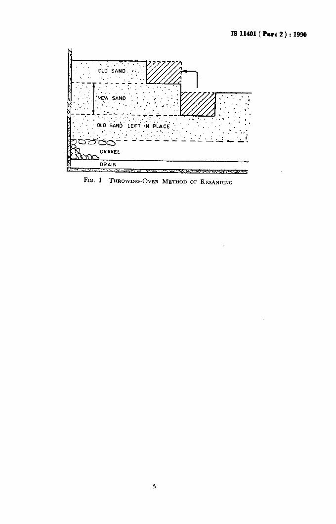
WhZn, after repeated scrapings, the sand depth in a filter bed has fallen to its minimum design level ( 0’5-0’6 m above gravel ) resanding has to be done and the sand depth restored to its design level ( 0’8- I’0 m ).
If, in resanding, new sand is placed directly over the old sand left in the bed there would be cumulative fouling of the latter as some of the raw water impurities and products of biological growth do penetrate to these layers also. Cumulative fouling is indicted by progressive increase in initial head loss (head loss immediately after filter scraping ) and will lead to shorter and shorter filter runs.
Cumulative fouling can be avoided by adopting the throwing over process of resanding. In this process, the bottom layer of sand is moved to vne side, new sand is placecl to make up the
level and the old sand is then put back on top of the new sand. Throwing over ensures that the bottom sand layer is also subjected to scraping in due course. It also ensures the presence of biologically active sand at the top after resanding which will help in quick re-ripening of the filter.
Throwing over is carried uut in strips. Excavation is carried out on each strip in turn, making sure that it is not dug as to disturb the gravel layers below. The removed material from first strip is stacked to one side in a long ridge; the excavated trench is filled with new sand and the adjacent strip is excavated, throwing the removed material from the second trench to cover the new sand in the first. When the whole of the bed has been resanded, the material in the ridge from the first trencl~ is used to COVCI‘ the new sand ilr tl~c last strip.
IS 11491 (Part 2 ) : 1990
FIG. 1 THROWING-OVER METHOD OF RESANDING

Stondrrd Mark I
The use of the Standard Mark is governed by the provisions of the Bureau of Indian Standards Act, 1986 and the Rules and Regulations made thereunder. The Standard Mark on products covered by an Indian Standard conveys the assurance that they have been produced to comply with the requirements of that standard under a well defined system of inspection, testing and quality control which is devised and supervised by BlS and operated by the producer. Standard marked products are also continuously checked by BIS for conformity to that standard as a further safe- guard. 1)etail.s of conditions under which a licence for the use of the Standard Mark may be granted to manufacturers or producers may be obtained from the Bureau of Indian Standards.

Bureau of Indian Standards
BIS is a statutory institution established under the Bureau of Indian Standards Act, 1986 to promote harmonious development of the activities of standardization, markin,g and quality certification of goods and attending to connected matters in the country.
Copyright
BIS has the copyright of all Its publications. No part of these publications may be reproduced in any form without the prior permission in writing of BIS. This does not preclude the free use, in the course of implementing the standard, of necessary details, such as symbols and sizes, type or grade designations. Enquiries relating to copyright be addressed to the Director ( Publications ), BIS.
Revision of Indian Standards
lndran Standards are reviewed periodically and revised, when necessary and amendments, if any, are Issued from time to time. Users of Indian Standards should ascertain that they are in possession of the latest amendments or edition. Comments on this Indian Standard may be sent to BIS giving the following reference:
Dot : No. CED 40 ( 4540 )
Amendments Issued Since Publication
Amend No. Date of Issue Text Affected
BUREAU OF INDIAN STANDARDS
Headquarters:
Manak Bhavan, 9 Bahadur Shah Zafar Marg, New Delhi 110002 Telephones : 331 01 31,331 13 75 Telegrams : Manaksanstha
( Common to all Offices )
Regional Offices:
Central : Manak Bhavan, 9 Bahadur Shah Zafar Marg NEW DELHI 110002
Eastern : l/14 C.I.T. Scheme VII M, V.I.P. Road, Maniktola CALCUTTA 700054
331 01 31 331 13 75
37 86 62
Northern : SC0 445-446, Sector 35-C, CHANDIGARH 160036
Southern : C.I.T. Campus, IV Cross Road, MADKAS 600113
Western : Manakalaya, E3 MIDC, Marol, Andheri (East) BOMBAY 400093
2 1843
41 29 16
6 32 92 95
Branches : AHMADABAD. BANGALOKE. BHOPAL. BHUBANESHWAR. COIMBATOKE. FAKIDABAD. (:HAZlABAD. GUWAHATI, HYDERABAT) JATPIJR. KANPlJR. PATNA. THTRUVAN.4NTHAPIJKAM.
.-_-..-- ._ ~- Printed at Arcae Press. New Delhi. India