is 12786 (1989): irrigation equipment - polyethylene pipes ... · is 12786 (1989): irrigation...
TRANSCRIPT
Disclosure to Promote the Right To Information
Whereas the Parliament of India has set out to provide a practical regime of right to information for citizens to secure access to information under the control of public authorities, in order to promote transparency and accountability in the working of every public authority, and whereas the attached publication of the Bureau of Indian Standards is of particular interest to the public, particularly disadvantaged communities and those engaged in the pursuit of education and knowledge, the attached public safety standard is made available to promote the timely dissemination of this information in an accurate manner to the public.
इंटरनेट मानक
“!ान $ एक न' भारत का +नम-ण”Satyanarayan Gangaram Pitroda
“Invent a New India Using Knowledge”
“प0रा1 को छोड न' 5 तरफ”Jawaharlal Nehru
“Step Out From the Old to the New”
“जान1 का अ+धकार, जी1 का अ+धकार”Mazdoor Kisan Shakti Sangathan
“The Right to Information, The Right to Live”
“!ान एक ऐसा खजाना > जो कभी च0राया नहB जा सकता है”Bhartṛhari—Nītiśatakam
“Knowledge is such a treasure which cannot be stolen”
“Invent a New India Using Knowledge”
है”ह”ह
IS 12786 (1989): Irrigation Equipment - Polyethylene Pipesfor Irrigation Laterals [FAD 17: Farm Irrigation andDrainage Systems]

IS : 12786 - 1989
Indian Standard
IRRIGATION EQU-IPMENT - POLYETHYLENE PIPES FOR IRRIGATION LATERALS -
SPECIFICATION
UDC 621.643.2 [ 678.742.2 ] : 631.67
0 BIS 1990
BUREAU OF INDIAN STANDARDS
MANAK BHAVAN, 9 BAHADUR SHAH ZAFAR MARG
NEW DELHI 110002
February 1990 Price Group 5

Irrigation Equipment and Systems Sectional Committee, FADC 35
FOREWORD
This Indian Standard was adopted by the Bureau of Indian Standard on 29 September 1989, after the draft finalized by the Irrigation Equipment and Systems Sectional Committee had been approved by the Food and Agriculture Division Council.
Drip irrigation systems is one of the modern irrigation techniques to economise the use of water in agriculture. It has a very high water use efficiency as it applies water directly to the plant root zone.
As the drip irrigation is becoming popular the requirements for the polyethelene pipes intended for irrigation laterals have been specified in this standard.
In preparation of this standard, assistance has been derived from ISO/DIS 8779 ‘Polyethylene ( PE ) pipes for irrigation laterals - Specification’ prepared by International Orgnizations for Standardization ( IS0 ) and IS 3G76 : 1985 ‘Specification for low density polyethylene pipes for portable water supplies ( second revision t.
For the purpose of deciding whether a particular requirement of this standard is complied with, the final value, observed or calculated, expressing the result of a test or analysis shall be rounded~off in accordance with IS 2 : 1960 ‘Rules for rounding off numerical values ( revised )‘. The number of significant places retained in the rounded off value should be the same as that of the specified value in this standard.
IS 12786 : 1989
Indian Standard
IRRIGATION EQUIPMENT - POLYETHYLENE PIPES FOR IRRIGATION LATERALS -
SPECIFICATION
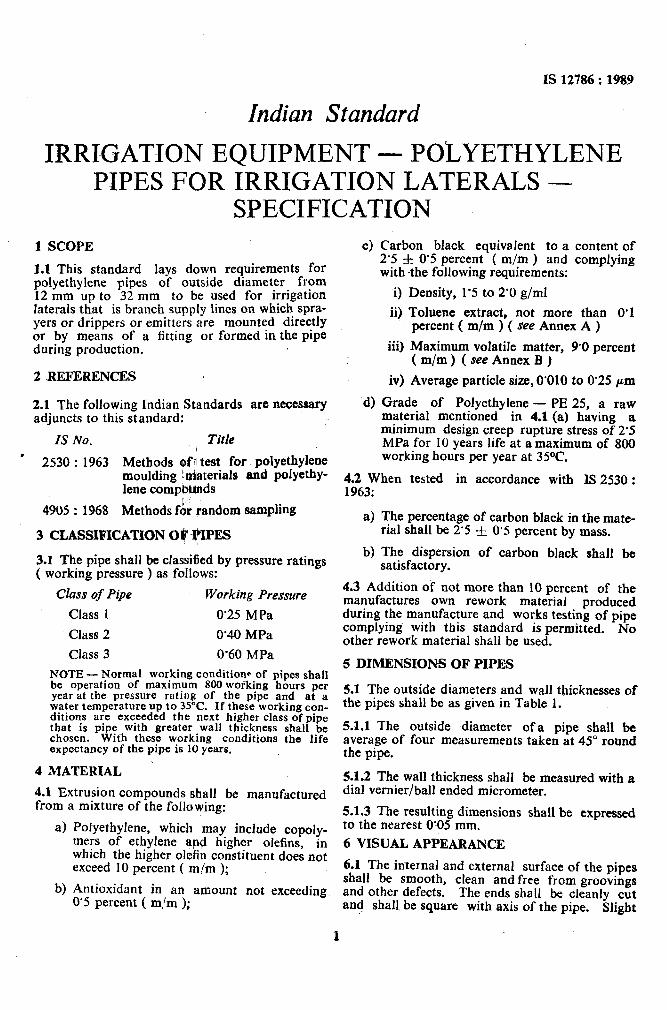
1 SCOPE
1.1 This standard lays down requirements for polyethylene pipes of outside diameter from 12 mm up to 32 mm to be used for irrigation laterals that is branch supply lines on which spra- yers or drippers or emitters are mounted directly or by means of a fitting or formed in the pipe during production.
2 aEFERENCES
2.1 The following Indian Standards are necessary adjuncts to this standard:
IS No. Title
’ 2530 : 1963 Methods olf’l test for polyethylene moulding !.miaterials and polyethy- lene comptilliltlds
4905 : 1968 Methods f& random sampling
3 CLASSIFICATION Oti $‘IPES
3.1 The pipe shall be classified by pressure ratings ( working pressure ) as follows:
Class of Pipe Working Pressure
Class 1 0’25 MPa
Class 2 ~0’40 MPa
Class 3 0’60 MPa
NOTE - Normal working condition- of pipes shall be operation of maximum 800 working hours per year at the pressure rating of the pipe and at a water temperature up to 35°C. If these working con- ditions are exceeded the next higher class of pipe that is pipe with greater wall thickness shall be chosen. With these working conditions the life expectancy of the pipe is 10 years.
4 MATERIAL .
4.1 Extrusion compounds shall be manufactured from a mixture of the following:
4
b)
Potyethylene, which may include copoly- mers of ethylene at@ higher olefins, in which the higher oleiin constituent does not exceed 10 percent ( m/m );
Antioxidant in an amount not exceeding 0’5 percent ( m/m );
c) Carbon black equivalent to a content of 2’5 f 0’5 percent ( m/m ) and complying with $he following requirements:
i) Density, 1’5 to 2’0 g/ml
ii) Toluene extract, not more than 0’1 percent ( m/m ) ( see Annex A )
iii) Maximum volatile matter, 9.0 percent ( m/m ) ( see Annex B )
iv) Average particle size, 0’010 to 0’25 pm
d) Grade of Polyethylene - PE 25, a raw material mentioned in 4.1 (a) having a minimum design creep rupture stress of 2’5 MPa for 10 years life at a maximum of 800 working hours per year at 35OC.
4.2 When tested in accordance with IS 2530 : 1963:
a) The percentage of carbon black in the mate- rial shall be 2’5 f 0’5 percent by mass.
b) The dispersion of carbon black shall be satisfactory.
4.3 Addition of not more than 10 percent of the manufactures own rework material produced during the manufacture and works testing of pipe complying with this standard is permitted. No other rework material shall be used.
5 DIMENSIONS OF PIPES
5.1 The outside diameters and wall thicknesses of the pipes shall be as given in Table 1.
5.1.1 The outside -diameter ~of a pipe shall be average of four measurements taken at 45” round the pipe.
5.1.2 The wall thickness shall be measured with a dial vernier/ball ended micrometer.
5.1.3 The resulting dimensions shall be expressed to the nearest 0:05 mm.
6 VISUAL APPEARANCE
6.1 The internal and external surface of the pipes shall be smooth, clean and free from groovings and other defects. The ends shall be cleanly cut and shall. be square with axis of the pipe. Slight
5s 12986 : 19s9
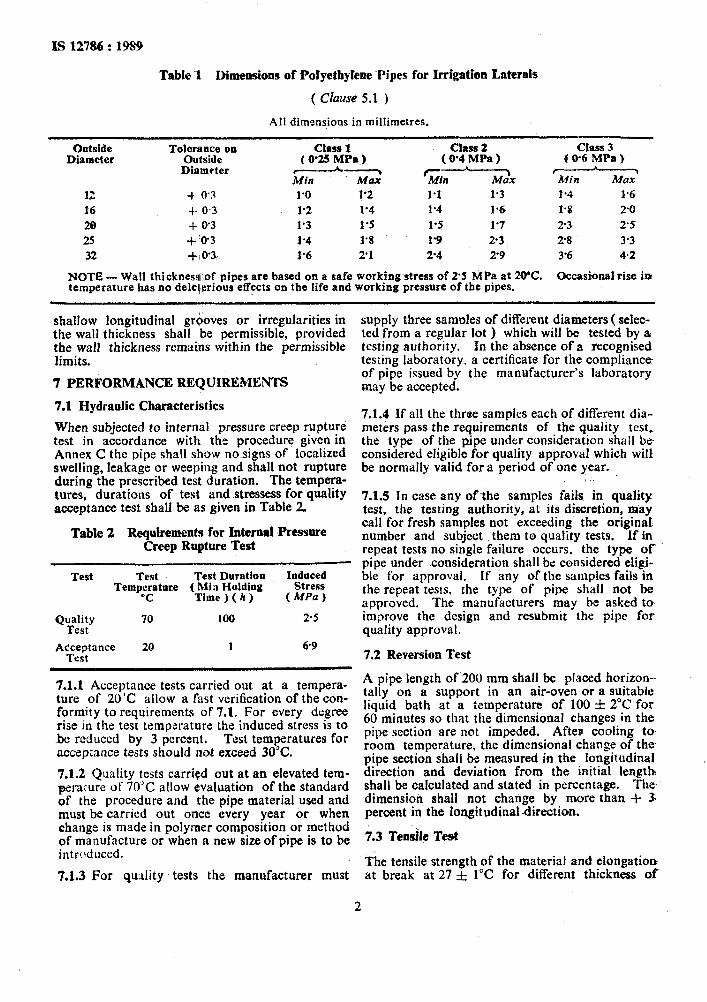
Table I Dimensions of Polyethylene ~Pipes for Irrigation Laterals
( CZuzLYe 5.1 )
All dimensions in millimetres.
Outside Diameter
12
16
29
25
32
T01;;;~ye on
Diameter
+ 0’3
$- o-3
+ 0’3
+ ‘0’3
+,0’3
Class 1 (0’25MPa)
----? Min Max 1’0 1’2
1’2 1’4
1’3 1’5
1.4 1’8
f’6 2’1
Class 2 ( 0.4 MPa )
rMil# Ml& 1.1 1.3
1.4 1.6
1’5 1’7
1’9 23,
24 2’9
NOTE -Wall thicknesq,.of pipes are based on a safe working~stress of 25 MPa at 2VC. temperature has no deleterious effects on the life and working pressure of the pipes.
Class 3 f@6 MPa)
--- Mitt MUX l-4 1.6 f-0 2-O 29 2’5 2-8 33 3% 4.2
Occasional rise ia
shallow longitudinal grooves or irregularities in the wall thickness shall be permissible, provided the wall thickness remains within the .permissible limits.
7 PERFORMANCE REQUIREMENTS
7.1 Hydraolic Characteristics
When subjected to internal pressure creep rupture test in accordance with the procedure given in Annex C the pipe shall show no-signs of localized swelling, leakage or weeping and shall not rupture during the prescribed test duration. The tempera- tures, durations of test and stressess for quality acceptance test shall be as given in Table 2.
Table 2 Requirements for Internal Pressure Creep Rupture Test
Test Test Test Durntion Temp:rture ( Mia Holding
Thne ) ( h )
Quality 70 100 Test
A&ecptance 20 1
Induced Stress
(MPG)
2.5
69
7.1.1 Acceptance tests carried out at a tempera- ture of 2O’C allow a fast verification of the con- formity to requirements of 7.1. ~For every degree rise in the test temperature the induced stress is to be reduced by 3 percent. Test temperatures for acceptance tests should not exceed 30°C.
7.1.2 Quality tests carried out at an elevated tem- peraiure of 70°C allow evaluation of the standard of the procedure and the pipe material used and must be carried out once every year or when ebange is made in polymer composition or method of manufacture or when a new size of pipe is to be introduced.
7.1.3 For quality tests the manufacturer must
supply three samples of different diameters ( seIec- ted from a regular lot ) which will be tested by L testing authority. In the absence of a recognised testing laboratory. a certificate for the compliance of pipe issued by the mnnwfacturer’s laboratory may be accepted.
7.1.4 If all the three samples each of different dia- meters pass the requirements of the quality test, the type of the pipe under consideration shall be considered eligible for quality approval which will be normally valid for a period of one year.
/..
.
7.1.5 In case any ofthe samples fails in quality test, the -testing authority, at its discretion, may call for fresh samples not exceeding the original number and subject them to quality tests. If in repeat tests no single failure occurs, the type of pipe under ~consideration shall be considered eligi- ble for approval. If any of the samples fails in the repeat tests, the type of pipe shall not be approved. The manufacturers may be asked to improve the design and resubmit the pipe for quality approval,
*’
7.2 Reversion Test
A pipe length of 200 mm shall be placed horizon- tally on a support in an air-oven or a suitable liquid bath at a temperature of 100 f 2°C for 60 minutes so that the dimensional changes in the pipe section are not impeded. After; cooling to room temperature, the dimensional change of the, pipe section shall be measured in the longittldinal direction and deviation from the initial length? shall be calculated and stated in percentage. The- dimensioh shall not change by more than + 5 percent in the longitudinal ~direction.
7.3 Tensile Test
The tensile strength of the material and elongation at break at 27 f 1°C for different thickness of
2
the pipes shall be as follows: Tensile Testing
Strength, Min Speed 10 MPa 100 mm/niin
7.3.1 Test Piece
Elongation at Break, Mirr
350 percent
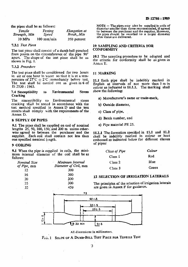
The test piece shall consist of a dumb bell punched from points on the circumference of the pipe 90” apart. The shape of the test piece shall be as shown in Fig. 1.
7.3.2 Procerfure
The test piece shall be conditioned tfor two hours in air or one hour in water so that it is at a tem- perature of 27°C & 2% immediately before test. The test shall be carried out as given in 6 of IS 2530 : 1963.
7.4 SusceptibiIity to Environmental Stress Cracking
The susceptibility $a Environmental stress cracking shall be tested in accordance with the test method specified in Annex D and the test results shall comply with the requirements of the Annex D.
8 SUPPLY OF PIPES
8.1 The pipes shall be supplied on coil of nominal lengths 25, 50, 100, 150, snd 200 m unless other- wise agreed to between ‘the purchaser and the supplier. Each coil shall contain not less than one specified nominal length.
I 9 COILING
9.1 W’hen the pipe is supplied in coiis, the mini- mum internal diameter of the coil shall be as follows:
Nominal Size Minimum Internal of Pipe, mm Diameter of Coil, mm
12 300 16 300 20 300 25 300 32 450
IS 12786 : 1989
NOTE - The pipes may also be supplied in coils of diameter smaller than those recommended, if agreed to between the purchaser and the supplier. However, the pipes should be recoiled to a larger diameter after these are delivered.
10 SAMPLING AND CRITERIA FOR CONFORMITY
10.1 The sampling procedure to be adopted and the criteria for conformity shall be as given in Annex E.
11 MARKING
11.1 Each pipe shall be indelibly marked in English at intervals of not more than 5 m in colour as indicated in 11.1.1. The marking shall show the ~following:
a) Manufacturer’s name or trade-mark,
b) Outside diameter,
c) Class of pipe,
d) Batch number, and
e) Pipe material PE 25.
11.1.1 The formation specified in 11.1 and 11.2 shall be indelibly marked in colour or heat embossed as indicated below for different classes of pipes:
Class of Pipe Colour
Class 1 Red
Class 2 Blue
Class 3 Green
12 SELECTION OF 1RRIGATION LATERALS
The principles of the selection of irrigation laterals are given in Annex F for guidance.
4 75 .
All dimensions in millimeters.
Fr;. 1 SH,~PEOP ADUMB-BELLTESTPIECB FORTENSILE TEST
3
IS 12786 : 1989
ANNEX A
[ Clause 4.1 (c) ]
DETERMINATION OF TOLUENE EXTRACT OF CARBON BLACK
A-l APPARATUS
A-l.1 Extraction Thimbles, double thickness, fat extracted.
A-I.2 Soxhlet Apparatus
A-1.3 Shallow Weighing Dish, 50 ml capacity, of borosilicate glass.
A-2 REAGENT
A-2.1 Toluene, Sulphur-free, of AR quality.
A-3 PROCEDURE
A-3.1 Place 5 to 8 g of pelletized carbon black or 2 to 5 g of compressed fluffy black in a paper extraction thimble. Insert the thimble into the soxhlet ~extractor. Measure 50 to 60 ml of toluene into the soxhlet flask.
A-3.2 Assemble the soxhlet apparatus and extract for 22 hours.
A-3.3 Evaporate successive small portions of the extract solution ( filtered, if necessary ) nearly to dryness in the previously cleaned, dried and tared 50 ml shallow glass weighing dish. Rinse the extraction flask with tdluene and add the washings, to the weighing dish. Evaporate the combined extracts on a hot-plate to a volume of approxi- mately 5 to 10 ml and finally the dish and contents in an oven at 115°C. until dry.
A-3.4 Cool in a desiccator to room temperature. and weigh.
A-4 CALCULATION
A-4.1 Calculate the toluene extract, percent as. follows:
Toluene extract
Mass of extract =.___ .__-~____ x 100 percent Mass of sample
ANNEX B
[ Clause 4.1 (c) J
DETERMINATION OF MAXIMUM VOLATILE MATTER IN CARBON BLACK
B-l APPARATUS
B-l.1 Electric Furnace
Capable of temperature regulation of f 25°C at 950°C and equipped with 4 thermocouple-activated indicating pyrometer.
B-1.2 Platinum Crucibles, 25 x 35 mm.
B-1.3 Petri Dish, 75 mm dia.
B-l.4 Oven
Electrically operated air-circulating type, capable of temperature regulation of fl”C at 1OO’C.
B-1.5 Analytical Balance, having a sensitivity of 0’1 mg.
B-l.6 Desiccator
B-2 PROCEDURE
B-2.1 Dry 5 g of the sample in an air-oven at 100°C for 2 hours.
B-2.2 Ignite two platinum crucibles in the electric furnace at 950 f25’C for about 30 minutes. Cool to about 200-C in an iron plate and place in the
4
!
desiccator. When these attain the room tempera-. ture, weigh them to the nearest 0. I mg.
B-2.3 Place 1 g of dried carbon black in the. weighed crucible leaving an air space not more than 2 mm.
B-2.4 Ignite the crucibles and contents in the electric furnace for exactly 7 minutes at a tern-- perature of 950 f 20°C.
B.2.5 Remove the crucible assembly to the desic- cator, allow to cool to room temperature and weigh to the nearest 0’1 mg.
B-3 CALCULATION
B-3.1 Calculate the percentage of volatile matter as follows:
Volatile matter Loss of mass
= Mass of sample taken x 100 percent
NOTE - The loss of volatile matter during drying operation is negligible.
.- I a
J

IS 12786 : 1989
. /
ANNEX C
( Cluuse 7.1 )
INTERNAL PRESSURE CREEP RUPTURE TESTS
C-l GENERAL
C-l.1 The test shall be carried out not earlier than 24 hours after the pipes have been manufactured.
C-2 TEST SPECIMEN
C-2.1 A specimen of pipe having free length between the end fittings equal to ten times the out- side diameter but not less than 250 mm for testing from each pipe to be tested.
C-3 APPARATUS
deviation f 1°C ) and kept in the bath for 1 hour to adjust the temperature.
C-4.3 The pressure in the pipe shall then be in- creased to the test pressure ( p ) gradually and without shock, preferably within 10 to 30 seconds in the bath whose~temperature has been adjusted in accordance with C-4.2. The pressure, with a permissible deviation of -12.5 percent, shall be maintained for the test period laid down in Table 2. The test pressure (p ) shall be calcu- lated from the minimum dimension and values of induced stress given in Table 2 as follows:
C-3.1 Equipment which permits the application of a controlled internal hydraulic pressure to the specimen while being immersed in a thermostati- cally controlled water-bath shall be used. where
C-4 PROCEDURE
C-4.1 The pipes shall be fitted with the locking plugs at both ends in such a way that the axial forces due to the internal pressure are transmitted to the pipe. The pipe shall remain free to move in lcngitudinal direction.
P = test pressure in MPa,
s = minimum wall thickness in mm,
G = induced stress in MPa, and
d = nominal outside diameter in mm.
C-5 ASSESSMENT OF RESULTS
C-4.2 Through a closable opening in one of the locking plugs, the pipe shall be filled with water
C-5.1 The specimen when tested as above shall
It shall then be put in a meet the requirements specified in 7.1. The tests
at ambient temperature. water-bath at the test temperature ( permissible
showing rupture within a distance d from the end cap shall be disregarded and the test repeated.
ANNEX D
( Clause 7.4 )
ENVIRONMENTAL STRESS CRACKING RESISTANCE TEST
D-l SCOPE AND FIELD OF APPLICATION
This standard specifies a test method used to detect, in a very short time, pipes which are poten- tially susceptible to environmental stress-cracking ( ESC ).
D-2 TEST METHOD
D-2.1 Reagent
An undiluted surface active agent of the type of nonylphenoxy poly ( ethyleneoxy ) ethanol [ Igepal CO-630 or Antarox CO-6301 may be used for reference purposes. This information is given for the convenience of users and does not consti- tute eindorsement of the product kept in closed contamers and used fresh for each test.
NOTE-If used in a bath, the reagent should be replaced every week,
D-2.2 Apparatus
Forced air circulation oven, maintained at 50 f3”C, capable of re-establishing that tempera-, ture within five minutes after insertion of test pieces.
NOTE - A constant temperature bath containing the reagent may be used, if it has the same thermal capabilities as the oven described above.
D-2.3 Test Pieces
Five sections of pipe, preferably from different coils, each of length about 20 times the diameter shall eonstitute the test piece.
5
PS 12786 : I989
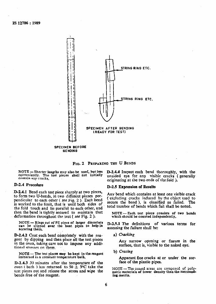
SPECIMEN AFTER BENDING (READY FOR TEST)
SPECIMEN BEFORE BENDING
FIG. 2 PREPARING THE U BENDS
NOTE -Shorter lengths may also be used, but less conveniently. The test pieces shall not initially
D-2.4.4 Inspect each bend thoroughly, with the
contain any cracks. unaided eye for any visible cracks ( generally originating at the two ends of the fold ).
D-2.4 Procedure D-2.5 Expression of Results D-2.4.1 Bend each test piece sharply at two pieces, to form two U-bends, in two different planes per- Any bend which contains at least one visible crack
pendicular to each other ( seeFig. 2 ). Each bend (-excluding cracks induced by the object used to
is worked to the limit, that is until both sides of. secure the bend ), is classified as failed. The
the fold touch and lie parallel to each other, and total number of bends which fail shall be noted.
then the bend is tightly secured to maintain that NOTE deformation throughout the test ( see Fig. 2 ).
-Each test piece carGists of two bends which should be counted independently.
NOTE - Rings cut of PE pipes of Jarger diameters ~45.1 The definitions can be slipped over the bent pipes to help in
of various terms for
securing them. assessing the failure shall be:
D-2.4.2 Coat each bend cbmpletely with the rea- a) Cracking gent by dipping and then place all the test pieces in the oven, taking care nat to impose any addi-
Any narrow opening or fissure in the
tional stresses on them. surface, that is, visible to the naked eyd
NOTE - The test pieces may be kept in the reagent immersed in a constant temprature bath.
-D-2.4.3 30 minutes after the temperature of the oven ( bath ) has returned to 50 f 3% take the test pieces out and release the stress and wipe the bends free of the reagent.
b) Crazing
Apparant fine cracks at or under the sur- face of the plastic pipes.
NOTE -The crazed areas are composed of poly- merit materials of lower density than the surround- ing matrix.
6
.1
is 127% F 1989
I) Bloom D-3 RETEST
A visible exudation or efflorescence on the D-3.1 If one bend failed while nine others did
surface of the pipe. not, the whole procedure is repeated with five further test pieces ( that is ten further bends ).
d) Rupture D-4 REQUIREMENTS
A break in the pipe wall with immediate D-4.1 The pipe is considered to have passed the loss of test fluid and continued loss of test if not more than 10 percent of the bends pressure. ( that is 1 out of 10 or 2 out of 20 ) have failed.
ANNEX E
( Clause 10.1 )
SCALE OF SAMPLING AND CRITERIA FOR CONFORMITY
E-l LOT
E-l.1 All pipes in a single consignment of the same outside diameter, same wall thickness, same length and manufactured essentially under similar conditions of manufacture shah constitute a lot.
E-1.2 For ascertaining the conformity of the material to the requirements of this specification, samples shall be tested from each lot separately.
Fr2 VIS11AL AND DIMENSIONAL REQUIREMENTS
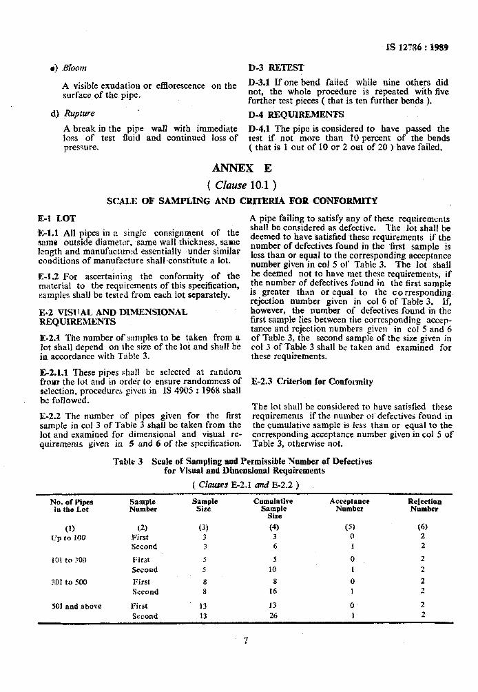
E-2.4 The number of s:unples to be taken from a lot shall depend on the size of the lot and shall be in accordance with Table 3.
E-2.1.1 These pipes shall be selected at random from the lot and in order to ensure randomness of selection, procedures given in 1s 4905 : 1968 shall be followed.
E-2.2 The number of pipes given for the first sample in co1 3 of Table 3 shalI be taken from the lot and examined for dimensional and visual re- quirements given in 5 and 6 of the specification.
A pipe failing to satisfy any of these requirements shall be considered as defective. The lot shall be deemed to have satisfied these requirements if the number of defectives found in the first sample is less than or equal to the-corresponding acceptance number given in co1 5 of Table 3. The lot shall be deemed not to have met these requirements, if the number of defectives found in the first sample is greater tha.n or equal to the corresponding rejection number given in co1 6 of Table 3. .lf, however, the number of defectives found in the first sample lies between the corresponding accep- tance and rejection numbers given in co1 5 and 6 of Table 3, the second sample of the size given in co1 3 of Table 3 shall be taken and examined for these requirements.
E-2.3 Criterion for Conformity
The lot shall be considered to have satisfied these requirements if the number 01’ defectives found in the cumulative sample is less than or equal to the corresponding acceptance number given in co1 5 of Table 3, otherwise not.
Table 3 Scale of Sampling and Permissible Camber of Defectives ~for Visual and Dimensional Requirements
( Clauses E-2.1 and E-2.2 )
No. of Yipes Sample in the Lot Number
(1) (2)
Cumulative SaW;
(4)
Acceptance Number
(5) IJp to 100 R;‘irst
Second 3 j 0 2 3 4 1 2
101 to 300 First 3 5 0 2
Second 3 10 I 2
301 to 500 First 8 8 0 2 Second 8 16 1 2
SO1 and above First 13 13 0 2 Second 13 26 1 2
IS 12786 : 1989
E3 REVERSION TEST
E-3.1 The lot having satisfied visual and dimen; sional requirements shall be tested for reversion. I
E-3.1.1 For this purpose, the first sample of~three pipes-shall be taken from the lot. The sample pipe failing in the reversion test shall be consider- ed as defective. If no defective is found in the first sample, the lot shall be deemed to have met the requirements given in the specification for reversion test. If, however, only one defective is found in the first sample, a second sample of three pipes shall be taken from the lot and tested for reversion.
E-3.2 Criterion for Conformity
The lot shall be deemed to have met the specifica- tion requirement for reversion given in 7.2 if not more than one defective is found in the cumula- tive sample, otherwise not.
E-4 HYDRAULIC AND TENSILE STRENGTH REQUIREMENTS
E-4.1 The lot having met the requirements given in E-2.2 and E-3 shall be finally tested for internal pressure creep rupture test lrpecified in 7.1 and tensile strength test specified lin 7.3.
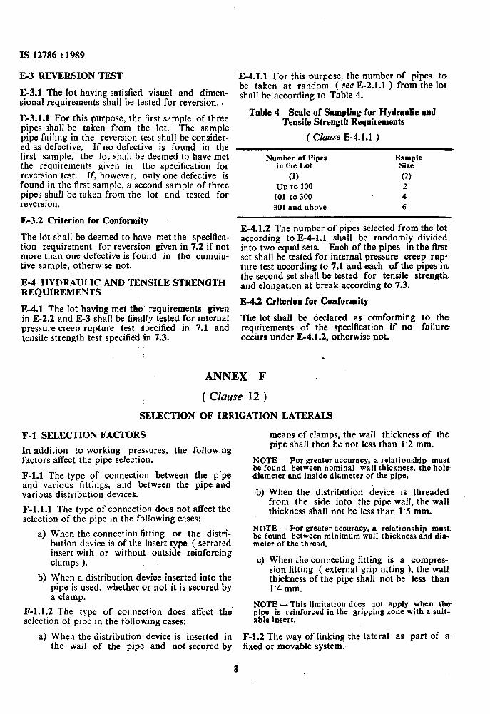
E-4.1.1 For this purpose, the number of pipes to be taken at random ( see E-2.1.1 ) from the lot shall be according to Table 4.
Table 4 Scale of Sampling for Hydraulic and Tensile Strength Requirements
( Clause E-4.1 .l )
Number of Pipes Sample in the Lot Size
(1) (2) up to 100 2
101 to 300 4
301 and above 6
E-4.1.2 The number of pipes selected from the lot according to E-4-1.1 shall be randomly divided into two equal sets. Each of the pipes in the first set shall be tested for internal pressure creep rup ture test according to 7.1 and each of the pipes in; the second set shall be tested for tensile strength and elongation at break according to 7.3.
E-4.2 Criterion for Conformity
The lot shall be declared as conforming to the requirements of the specification if no failure- occurs under E-4.1.2, otherwise not.
.
ANNEX F
( Chuse- 12 )
SELECTION OF IRRIGATION LATERALS
F-l SELECTION FACTORS
In addition to working pressures, the following factors affect the pipe selection.
F-l.1 The type of connection between the pipe and various fittings, and between the pipe and various distribution devices.
F-1.1.1 The type of connection does not affect the selection of the pipe in the following cases:
a) When the connection fitting or the distri- bution device is of the insert type ( serrated insert with or without outside reinforcing clamps ).
b) When a distribution device inserted into the pipe is used, whether or not it is secured by a clamp.
F-1.1.2 The type of connection does affect the’ selection of pipe in the following cases:
a) When the distribution device is inserted in the wall of the pipe and not secured by
means of clamps, the wall thickness of the pipe shall then be not less than 1’2 mm.
NOTE -For greater accuracy, a relationship must be found between nominal wall thickness, the~hole. diameter and inside diameter of the pipe.
b) When the distribution device is threaded from the side into the pipe wall, the wall thickness shall not be less than 1’5 mm.
NOTE - For greater accuracy, a relationship must. be found between minimum wall thickness and dia- meter of the thread.
c) When the connecting fitting is a compres- sion fitting ( external grip fitting ), the wall thickness of the pipe shall not be less than 1’4 mm.
NOTE -This limitation does not apply when the pipe is reinforced in the gripping zone with a suit- able .insert.
F-l.2 The way of linking the lateral as part of a. fixed or movable system.
8
Is 12786 : 1989
F-1.2.1 In a semi-mobile sprinkler system, the pressure of the pipe is determined according to the lateral shall not be less than a Class 3 pipe. maximum marking pressure in the pipe.
F-1.2.2 In a trailer-type drip irrigation SYStemI the lateral shall not be less than a Class 2 pipe:
F-1.3.2 At temperatures of 36 to 40°C the pipe shall be selected according to the next higher
F-l.3 Effect of water temperature on selection of class of pipe series listed in Table 1, so as to
nominal pressure of pipe. obtain a pipe with greater wall thickness for example if the working pressure is V25 MPa use
F-1.3.1 At temperatures up to 35”C, the nominal 0’40 MPa pipe.
9
.-.--ll_. .~..____I___-~.- --..
Standard Mark
The use of the Standard Mark ia governed by the provisions of the Bureau of Indian Standards Act, 1986 and the Rules and Regulations made thereunder. The Standard Mark on products covered by an Indian Standard conveys the assurance that they have been produced to comply with the requirements of that standard under a well defined system of inspection, testing and quality control which is devised and supervised by BIS and operated by the producer. Standard marked products are also continuously checked by BIS for conformity to that standard as a further safeguard. Details of conditions under which a licence for the use of the Standard Mark may be granted to manufacturers or producers may be obtained from the Bureau of Indian Standards.

Bureau of Indian Standards
BIS is a statutory institution established under the Bureau of Indian Standards Acr, 1986 to promote harmonious development of the activities of standardization, marking and quality certification of goods and attending’*0 connected matters in the country.
Copyright
BIS has the copyright of a11 its publications. NO part of these publications may be reproduced in any form without the prior permission in writing of BIS. This does not preclude the free use, in the course of implementing the standard, of necessary details, such as symbols and sizes, type or grade designations. Enquiries relating to copyright be addressed to the Director ( Publications ). BIS.
Revision of Indian Standards
Indian Standards are reviewed periodically and revised, when necessary and amendments, II any, are issued from time to time. Users of Indian Standards should ascertain that they are in possession of the latest amendments or edition. Comments on this Indian Standard may be sent to BlS giving the following reference:
Dot : No. FAD 35 ( 3041 1
Amendments Issued Since Publicdon
Amend No. Date of Jssue Text Affected
-
BUREAU OF
Headquarters :
Manak Bhavan. 9 Bahadur Shah Zafar Marg, Telephones : 331 01 31. 331 I3 75
Rogiontll Officer :
INDIAN STANDARDS
New Delhi 110002
Central : Manak Bhavan, 9 Bahadur Shah Zafar Marg NEW DELHI 110002
Bastorn : l/14 C. I. T. Scheme VII M, V. 1. P. Road, Maniktola CALCUTTA 700054
Northern : SC0 445446, Sector 35-C. CHANDIGARH 160036
Southern : C. I. T. Campus, IV Cross Road, MADRAS 600113
Western : Manakalaya, E9 MIDC, Marol, Aadheri ( Ept ) BOMBAY 400093
Telegrams : Manakaanetha ( Common to all OHices )
Telephone
1 331 331 01 13 75 31
36 24 99
1 2 3 1843 1641
41 24 42 41 25 19 41 29 16
‘b3292ii5
Branches : AHMADABAD. BANGALORE. BHOPAL. BHUBANESHWAR. GUWAHATI. HYDERABAD. JAIPUR. KANPUR. PATNA. TRIVANDRUM.
.
Printed at Printwell Priotrrr. Delhi, India
’11
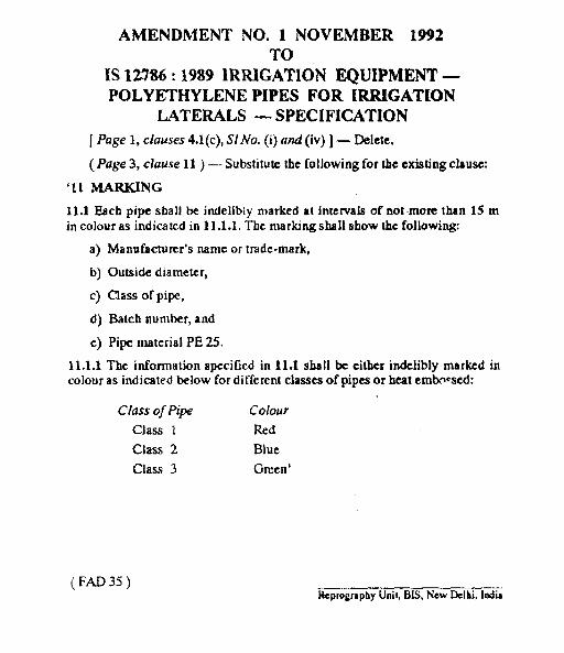
AMENDMENT NO. 1 NOVEMBER 1992TO
IS 12786:1989 IRRIGATION EQUIPMENT —POLYETHYLENE PIPES FOR IRRIGATION
LATERALS — SPECIFICATION
[ Page 1, clauses 4.1(c), SIAfo. (i) and (iv)] — Delete.
(Page 3, clause 11 } — Substitute the [ollowing for the existing clause:
MARKING
11.1 Each pipe shall be indelibly marked at intervals of not-more than 15 min colour as indicated in 11.1.1, Titc marking shall show the followin&
a) Manufacturer’s name or tmde-mark,
b) Outside diameter,
c) Class of pipe,
d] Batch number, and
e) Pipe material PE 25.
11.1.1 The information apecificd in 114 sba 11he either indelibly marked incolour as indicsted below for di fferent classes of pipea or heat embwsed:
C[ass of Pipe Colow
Class 1 Red
Class 2 Blue
Class 3 Great’
(FAD35)ReprographyUni{,BE, New Delhi,1=
NOIJV~Idi03dS—S’IV213J4VlINOLLVWWWZIOdSIIdld3NWIiKHMlA~Od
‘JAlW4dIfl?)3NOLLVWlilH6861:98UHS1ml
8661I13WW03UZ“ONkN3JW(Ih31W
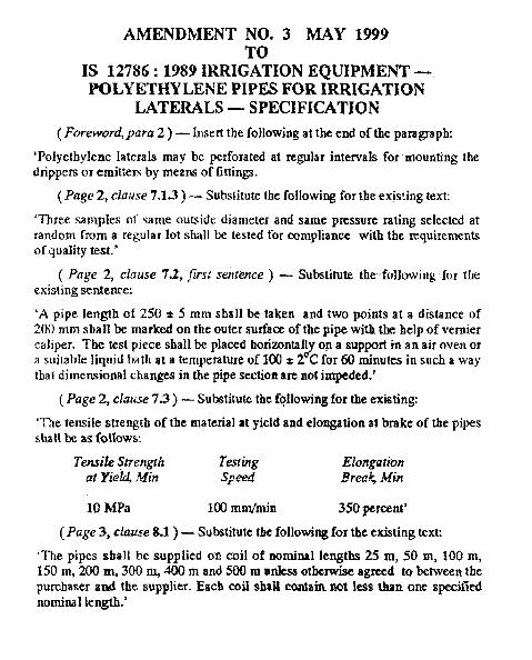
AMENDMENT NO. 3 MAY 1999TO
IS 12786:1989 IRRIGATION EQUIPMENT —POLYETHYLENE PIPES FOR IRRIGATION
LATERALS — SPECIFICATION
( Foreword,para 2 ) — Insert the following at the end of the paragraph:
‘Polyethylene laterals may be perforated at regular rntewals for mounting thedrippers or emit[em by means of fittings.
(Page 2, clause 7.1.3) — Substitute the following for the existing text:
‘Three sarnpIes d’ same outside diameter and same pressure rating selected atrandom from a regular lot shall be tested for compliance with the requirementsof quality tesl.’
( Pfrge 2, clause 7.2, Jiwsl sen(ence ) — Substitute the following for theexisting sentence.
‘A pipe length of 250 * 5 mm shall be taken and two points at a distance of200 mm shall be marked on the outer surfacz of the pipe with the help of verniercaliper. The test piece shall be placed horizontal y on a support in an air oven orz sui~b!e liquid bath at a temperature of 100 t 2°C for 60 minutes in such a waythat dimensional changes in the pipe section are not impeded.’
(Page 2, clause 7S ) — Substitute the ff$lowing for the exiatingq
‘The tensile strength of the material at yield and elongation al brake of the pipesshall be as Wlows:
Tensife Strength T14ng ElongationZr Y&?%Milt Speed &@d+ -$f~fi
10 MPa 1(KImrn/min 350 percent’
(Page 3, clause 8.1) — Substitute the following for the existing text
The pipes shalI be supplied ofi cd of nomfml lengths 25 m, 50 m, 100 m,150 m, 200 m, 300 m, 400 m and S00 m urtfesa otherwise agreed to betweert tbepurchaser and the sup#ier. Each eoif shall contain not less than one specifiednominal length.’
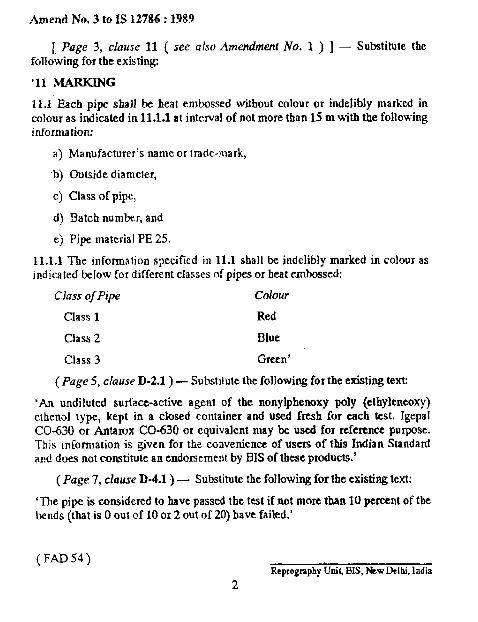
.4rnend No. 3 to IS 12786:1989
[ Page 3, clause 11 ( xee CISOAmendmenf No. 1 ) J – Substitute thefollowing for the existing
’11 MARKING
11J Each pipe shall be heat embossed without colour or indelibly marked incokmr as indicated in 11.1.1 at interval of not more than 15 m with the followinginforrtration:
a) Manufacturer’s name or lrade-mark,
b) Outside diameler,
c) Class of pipe,
d) Batch number, and
c) Pipe material PE 25.
11.1.1 The information specified in 11.1 shall be indelibly marked in colour asindieated below for different classes of pipes or heat embossed:
Class ofPipe Colour
Class 1 Red
Class 2 Blue
class 3 Green’
(Page 5, chwse D-2.1 ) – Substitute the following for the existing text
‘M undiiuted surface-active agent of the nonylphenoxy poly (ethyleneoxy}etheno] type, kept in a closed container and USed fresh for each test. IgepaiCO-630 or Antarox CO-630 or equivalent may be used for referenee purpose.This infomlation is given for the convenience of users of this Indian Standardand does not constitute an endorsement by BIS of these products.’
(Page 7, chruse D.4.1 ) – Substitute the following for the existing text:
‘The pipe is considered to have passed the test if not more than 10 percent of thebends (that is Oout of 10 or 2 out of 20) have failed.’
(FAD54)ReprographyUriiLBIS,NewDelhi,India
2
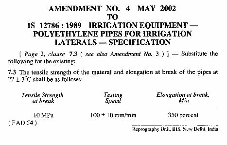
AMENDMENT NO. 4 MAY 2002TO
1S 12786:1989 IRRIGATION EQUIPMENT —POLYETHYLENE PIPES FOR IRRIGATION
LATERALS — SPECIFICATION
[ Page 2, clause 7.3 ( see also Amendment No. 3 ) ] — Substitute thefollowing for the existing:
7.3 The tensile strength of the materal and elongation at break of the pipes at27 ~ 3°C shall be as follows:
Tens~~b~e:~gth Testini
Elcmgati~i,:t break,Spee
10 MPa 100 ~ 10 mm/min 350 percent( FAD 54 )
Reprography Unit, B IS. Ncw Delhi, India
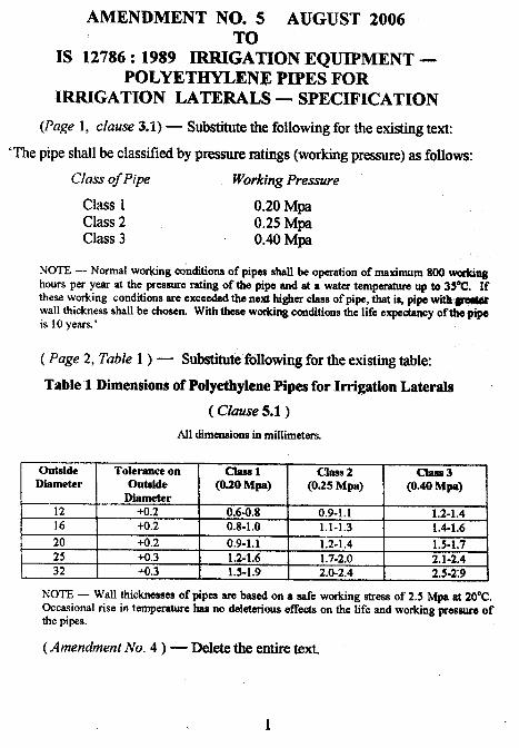
AMENDMENT NO. 5 AUGUST 2006TO
IS 12786:1989 IRRIGATION EQUIPMENT —POLYETHYLENE PIPES FOR
IRRIGATION LATERALS — SPECIFICATION> (Page 1, clause 3.1) — Substitute the following for the existing text
‘The pipe shall be classifkd by pressure ratings (working pressure) as follows:
Class of Pipe Working Pressure
class 1 0.20 MpaClass 2 0.25 Mpaclass 3 0.40 Mpa
NOTE — Normal wor@ng conditions of pipes shall be operation of maximum 800wuskinghoursperyemat the pressureratingof the pipeandat a watertemperatureupto 35%2.Ifthese workkg condithms are exceeded the next higher class of pipe, that i%pipe witls#e#@wall thickness shall be chosen, With these working conditions the life expeetmwy of the pipeis 10 ycsrs.’
( Page 2, Table 1 ) — Substitute following for the existing table:
Table 1 Dimensions of Polyethylene Pipes for Irrigation LateralsJi%-
( Clause 5.1)
AH dimensions in millimeters,
Outside Tolerance on Chsl-1Diameter outside (0.20 Mpa) (O%M;a) (O%M;)
Diameter12 +0.2 0.6-0.8 0.9-1.1 1.2-1.416 +0.2 0.8-1.0 1.1-1.3 1.4-1.6
20 +0.2 0.9.1.1 1.2-1.4 1.5-1,725 +0.3 1.2-1.6 1.7-2.0 2.1-2.432 +0.3 1.5-1.9 2.0-2.4 2.5-2:9
NOTE — Wall thicknesses of pipes are based on a safe working stress of 2.5 Mpa at 20°C.Occasional rise in temperature has no deleterious effects on the life and worMmg pressure ofthe pipes.
(Amendment No. 4 ) — Delete the entire text.
1
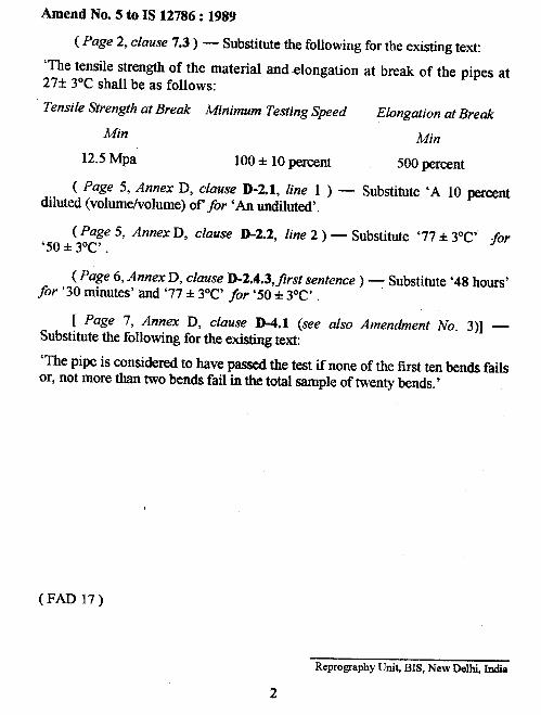
Amend No. 5 to IS 12786:1989
( Page 2, clause 7.3) — Substitute the following for the existing text:
‘The tensile strength of the material and-elongation at break of the pipes at27* 3°C shall be as follows:
Tensi[e Strength at Break Minimum Testing Speed Elongation at Break
Min Min
12.5 Mpa 100 * 10 percent 500 percent
( %ge %XbmexD, ck?use D-2.1, line 1 ) — Substitute ‘A 10 Wr~ntdiluted (volumeholume) of for ‘An undiluted’.
( Page 5, Annex D, clause D-2.2, line 2 ) — substitute ’77* 3“C’ for’50 * 3y!’ .
( Page 6, Annex D, clause D-2.4.3, first sentence ) - Substitute ’48 hours’for ’30 minutes’ and ‘77-* 3°C’ for ’50+ 3°C’ .
[ Page 7, Annex D, clause D-4.1 (see also Amendment No. 3)] —Substitute the following for the existing text:
‘The pipe is considered to have passed the test if none of the first ten bends failsor, not more than two bends fail in the total sample of twenty bends.’
(FAD 17)
Reprography Unit BIS, New Delhi, India
2
----- .-. . .