is 13270 (1992): test for gases by orsat and
TRANSCRIPT

Disclosure to Promote the Right To Information
Whereas the Parliament of India has set out to provide a practical regime of right to information for citizens to secure access to information under the control of public authorities, in order to promote transparency and accountability in the working of every public authority, and whereas the attached publication of the Bureau of Indian Standards is of particular interest to the public, particularly disadvantaged communities and those engaged in the pursuit of education and knowledge, the attached public safety standard is made available to promote the timely dissemination of this information in an accurate manner to the public.
इंटरनेट मानक
“!ान $ एक न' भारत का +नम-ण”Satyanarayan Gangaram Pitroda
“Invent a New India Using Knowledge”
“प0रा1 को छोड न' 5 तरफ”Jawaharlal Nehru
“Step Out From the Old to the New”
“जान1 का अ+धकार, जी1 का अ+धकार”Mazdoor Kisan Shakti Sangathan
“The Right to Information, The Right to Live”
“!ान एक ऐसा खजाना > जो कभी च0राया नहB जा सकता है”Bhartṛhari—Nītiśatakam
“Knowledge is such a treasure which cannot be stolen”
“Invent a New India Using Knowledge”
है”ह”ह
IS 13270 (1992): Test for gases by orsat andchromatographic methods [CHD 32: Environmental Protectionand Waste Management]


IS 13270 : 1992
Indian Standard
TESTFORGASESBYORSATAND CHROMATOGRAPHICMETHODS-
METHODS
UDC 543’27 : 543’54
@ BIS 1992
BUREAU OF INDIAN STANDARDS MANAK BHAVAN, 9 BAHADUR SHAH ZAFAR MARG
NEW DELHI 110002
&?rch 1992 Price Group 4

Environmental Protection Sectional Committee, CHD 012
FOREWORD
This lcdian Standard wzs sdopted by the Bureau of Indian Standards, after the draft finalized by the Environmental Protection Sectional Committee had been approved by the Chemical Division Council.
Orsat analysis and chromatographic gas analysis are ccmmonly used. Each one has some advantages and disadvantages. These ar’e listed below:
Orsat Analysis Chromatographic Analysis
Advantages
Gasometric ( volumetric procedures ) Gas chromatographic analysis 1 The equipment required is relatively simple. 2 It does not require any calibration.
3 When the analysis is done on an infrequent basis, it is very useful.
4 Simple to operate.
Disadvantages
1 Errors may be due to collection storage and handling of samples.
2 Unless special care is taken in the collec- tion of samples contamination by air
occurs.
3 Mercury is an ideal confining liquid/fluid because of the solubility of all gases in it. Rut practically it cannot be used due to great density and cost. Hence saturated salt/water is used for ordinary purposes.
4 It cannot measure concentrations of gases below 0 2 percent.
1 It has a great advantage of speed. 2 A gas analysis can be completed in few
minutes. 3 It can be used for low range.
4 The method is suitable for continuous analysis, as the instrument needs calibra- tion before use.
1 Instrument must have been previously calibrated for each gas of interest.
2 The oven must have reached a constant temperature and the detector must be giving stable response.
3 It is very difficult to carry instrument to the site. If the sample is collected in gas holder or any other equipment, collection, storage or handling becomes a problem.
4 It requires inert gas cylinder.
In reporting the result of a test or analysis made in accordance with this standard, if the final value, cbserved or calculated, is to be rounded off, it shall be done in accordance with IS 2 : 1960 ‘Rules for rounding off numerical values ( revised )‘.
Indian Standard IS 13270 : 1992
TESTFORGASESBYORSATAND CHROMATOGRAPHICMETHODS-
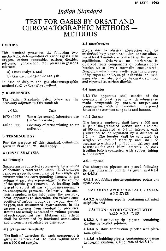
METHODS 1 SCOPE 4.3 Interferences
This standard prescribes the following two methods for determination of various gases like oxygen, carbon monoxide, carbon dioxide, nitrogen, hydrocarbon, etc, present in gaseous mixtures:
a) Orsat analysis, and b) Gas chromatographic analysis.
In case of dispute the gas chromatographic method shall be the refree method.
2 REFERENCES
The Jndian Standards listed below are the necessary adjuncts to this standard:
IS No. Title
1070 : 1977 Water for general laboratory use ( second revision )
4167 : 1980 Glossary of terms relating to air pollution.
3 TERMINOLOGY
For the purpose of this standard, definitions given in IS 4167 : 1980 shall apply.
4 ORSAT ANALYSIS
4.1 Principle
Sample gas is contacted successively by a series of chemically reactive solutions. Each solution removes a specific constituent of the sample gas mixture with the corresponding decrease in gas volume at each step representative of the volume of the specific gas removed. A levelling bulb is used to adjust all gas volume measurements to atmospheric pressure. Ordinarily, the ana- lysis is apphed in the field using the portable, orsat apparatus to determine the volume com- position of carbon monoxide, carbon dioxide, -oxygen_, and unsaturated hydrocarbons in the gaseous emission from combustion processes. Results are usually expressed in volume percent of each component gas. Methane and ethane shall be determined by fractional combustion and nitrogen is calculated by difference.
4.2 Range and Sensitivity
The limit of detection for each component is given as 0’2 percent of the total volume based on a 100’0 ml sample.
Errors due to physical absorption can be minimized by proper air-solution contact allow- ing at least 3 minutes as contact time for proper equilibrium. Otherwise, no interference is observed from components of ordinary com- bustion air at levels normally encountered. Negligible interference results from the presence of hydrogen sulphide, sulphur dioxide and acid gases which are absorbed by the caustic solution and reported as carbon dioxide.
4.4 Apparatus
4.4.1 The apparatus shall consist of the conventional orsat type in which volumes are made comparable by pressure temperature compensator, with a manometer interposed between the compensating tube and burette.
4.4.2 Burette
The burette employed shall have a 600 mm length of the graduated section with a volume of 100 ml, graduated at 0’2 ml intervals, each graduation to be separated by a distance of 1‘2 mm. The burette shall be calibrated by weighed volumes of mercury and shall be accurate to within 0’1 ml/100 ml delivery and to 0’02 ml for each 10 ml intervals. A glass levelling bulb is connected with rubber tubing to the burette.
4.4.3 Pipette
Gas absorption pipettes are placed following the gas measuring burette as given in 4.4.3.4 to 4.4.3.6.
4.4.3.1 A bubbling pipette containing potassium hydroxide.
CAUTION : AVOID CONTACT TO SKlN AND EYES
4.4.3.2 A bubbling ~pipette containing activated sulphuric acid.
CAUTION : AVOID CONTACT WITH SKIN AND EYES
4.4.3.3 A distributing tip pipette containing alkaline pyrogallol solution.
4.4.3.4 A slow combustion pipette with plati- num spiral.
4.4.3.5 A bubbling pipette containing potassium hydroxide solution. ( Duplicate of 4-4-3-1).
1

IS132:0:1992
4.4.3.6 A distributing tip pipette containing alkaline pyrogallol solution ( Duplicate of 4.4.3.3 ).
4.4.3.7 These pipettes must possess smooth surface which will not entrap gas bubbles, acd shall be so sufficient as to absorb the following gases from the sample after the required number of contacts with reagents.
Gas Number of Contacts with Reagents
Oxygen 4 to 5
Carbon dioxide 3
Unsaturated hydrocarbons 3
4.4.4 Manometer
The apparatus shall be of reproducibility of measurement of 0’02 ml per single contact or 0’05 ml on three successive contacts using the same reference gas or air.
4.5 Reagents
4.5.1 Quality of Reagents
Unless specified, otherwise, pure chemicals and distilled water ( see IS 1070 : 1977 ) shall be employed in tests.
NOTE - ‘Pure chemicals’ shall mean chemicals that do not contain impurities shich affect the results of analysis.
4.5.2 Potassium Hydroxide Solution Saturated
In 200 ml of distilled water, dissolve solid potassium hydroxide until excess potassium hydrcxide remains. Cool the saturated solution to at least 3°C below lowest expected tempera- ture at which analysis will be carried out. Decant and store the supernate liquid.
45.3 Activated Sulphuric Acid
Concentrated sulphuric acid containing silver sulphate or vanadium pentoxide.
4.5.4 Alkaline Pyrogallol Solution
Dissolve 17 g of pyrogallol crystals in 100 ml of potassium hydroxide solution ( 4.5.2 ). Store under rcfregeration in a glass-stoppered bottle.
4.5.5 Acidic Copper (II) Chloride Solution
Dissolve 450 g of copper (II) chloride in 2 500 ml of hydrochloric acid ( relative density 1’18 ). If this solution appears greenish or black in colour after preparation strips or turnings of copper shall be added to the solution until a straw- yellow coloured liquid is produced on standing. Store solution over copper turnings or wire.
4.5.6 Sodium Hydrate Asbestos Absorbent
Used when an unusually accurate measure of carbon dioxide is required. This absorbent may also be used to remove sulphur dioxide for a more accurate determination of unsaturated hydrocarbons.
4.5.7 Saturated Salt Solution - 75 percent.
Contains 30 g of sodium chloride or sodium sulphate or both, 5 ml of hydrochloric acid, 2 drops of methyl red per 100 ml of distilled water.
4.6 Procedure
4.6.1 Analysis with Portable Apparatus for Carbon Dioxide Oxygen and Carbon Monoxide
The portable orsat apparatus is fitted with a metal or wooden carrying case and uses a shortened form of burette with three gas absorb- ing pipettes. In order, starting from the burette, the pipettes are filled with potassium hydroxide, pyrogallol and cuprous chloride solution res- pectively. After filling the above pipettes to the engraved mark with the above solutions and before starting the test adjust the level of each to atmospheric pressure using the levelling bulb. Open the stopcock of the burette to the atmos- phere. Raise the levelling bulb until the burette fills to the stopcock with salt water ( saturated). Connect the stopcock -of the burette to the atmosphere to be sampled or to a sample con- tainer and fill the burette with sample gas by lowering the levelling bulb until the meniscus of the water level reads the desired volume in the burette ( I’,). Open the stopcock connecting the burette to manifold of the absorbing system and also open the stopcock of the potassium -hydroxide pipette. Pass the gas contained in the burette into the potassium hydroxid pipette by first raising and then lowering the levelling bottle. Repeat until three to five full contacts have been made. Return the remainder of the gas sample to the burette using the levelling bulb-until the level of potassium hydroxide solution returns to the engraved mark, and with the pipette stopcock closed, again, adjust the water level in the burette to atmospheric pres- sure using the levelling bulb. Measure the volume V, of the remaining gas and record the percent carbon dioxide as follows:
Carbon dioxide, percentage = loo ( ‘\- Va ) 1
Similarly, oxygen is removed from the remaining gas volume V, by passing this gas into the pyrogallol solution in the second pipette. Measurement of the remaining volume, V, is used to calculate the percent oxygen as follows:
Oxygen, percent = 100 ( V, - Vs )
V1
2

IS 13270 : 1992
Carbon monoxide is measured by mnnipulating the remaining gas volume V3 as done previously to admit this sample into the pipette containing copper (II) chloride. However, before returning the gas volume V, to the burette for measure- ment, volume V4 % passed once into the potas- sium hydroxide pipette to remove any hydro- chloric acid vapours evolved from copper (II) chloride.
Carbon monoxide, = 100 ( V, - V4 ) percent
Vl
4.6.2 Analysis by Constant Pressure Volumetry
In the laboratory bench apparatus the burette is filled with mercury and enclosed in a water jacket. The pipettes are connected to the burette by a manifold and a bubbling pipette containing sulphuric acid ( 4.4.3.2 ) is used together with a slow combustion pipette (4.4.3.4) which is equipped with a separate levelling bulb. Pipettes (4.4.3.5 and 4.4.3.6 ) are added to the system. Results of both absorption and combustion analyses are reported.
4.6.3 Removal of Gases by Absorption Analysis
Transfer 95 to 100 ml of the sample gas $0 the burette allowing 2 to 3 minutes for attaining temperature and humidity equilibrium. Using the leveling bulb bring the sample volume to atmospheric pressure and read the exact volume VI.
4.6.3.1 Removal of carbon dioxide ( or acid gases )
Displace the gas sample into the manifold and then transfer into the potassium hydroxide pipette. Return the sample gas to the burette. Then contact the potassium hydroxide pipette twice, finally returning the sample to the burette and allowing 2 to 3 minutes before equilibrating the sample to atmospheric pressure with the leveling bulb. Then read the volume V,.
4.6.3.2 Removal of amsaturated hydrocarbon
Displace the gas sample from the manometer arm and pass twice in and out of the pipette containing activated sulphuric acid. Transfer the sample to the potassium hydroxide pipette return to the sulphuric acid pipette for two successive contacts. Finally return to the burette for measurement F’s of the gas after standing 3 minutes in the burette.
4.6.3.3 Re.moval of oxygen
Displace the gas sample from the manometer and transfer twice to the pipette containing alkaline pyrogallol, then transfer to the potas- sium hgdroxide pipette and the sulphuric acid pipette in sequence. Finally transfer twice to the alkaline pyrogallol pipette and return to the burrette for measurement of the residual volume ( V4). When acid gases, oxygen and .unsaturated hydrocarbons occur at levels below
0’5 perc:nt they are best determined using reaction tubes rather than -pipettes.
4.6.4 Combustion Analysis
Prepare nitrogen to be used as a transfer gas by absorption of oxygen from uncontaminated air by contact with alkaline pyrogallol pipette. Flush the manifold with this nitrogen, then transfer approximately 40 ml of the pure nitrogen to the duplicate potassium hydroxide pipette ( 4.4.3.5 ) for storage V,. Transfer approximstely 95 ml of pure cylinder oxygen V, to the burette; measure and transfer to the slow combustion pipette for storage. Lst the inert impurities shown by the published analysis of this cylinder oxygen be represented as VT. Measure a fresh 30 to 35 ml of sample gas V, through the fuming sulphuric acid pipette prior to combustion analysis.
With the combustion gas sample contained in the burette adjust the pressure in the combustion pipette and the burette to atmospheric and with the platinum wire glowing dull red op:n the combustion pipette and slowly admit the gas sample over the hot platinum wire. Allow a full 15 minutes for the first pass of sample into the bomb combustion tubs. When all of the gas sample has been transferred to the combus- tion pipette, displace the gas contained in the manometer arm through the distributer into the combustion pipette. Over a period of about 5 minutes, return the contents of the combustion pipette to the burette until the mercury level is just below the platinum spiral, then return the gas slowly to the combustion pipette and repeat the slow combustion three times. Allow the final pass of sample gas in the combustion pipette to cool before returning to the burette. Measure this residue and record as V,.
4.6.4.1 Removal of carbon dioxide produced by combustion
Displace the gas from the manometer and the contents sample residue in the burette into the duplicate potassium hydroxide pipette ( 4.4.3.5 ) three times. Return this sample volume to the combustion pipette and then repeat contact with the potassium hydroxide solution before return- ing to the burette for measurement as VIO.
4.6.4.2 Removal of excess oxygen after combustion
Dissolve the sample gas from the manometer and contact 4 times in the duplicate alkaline pyro- gall01 pipette ( 4.4.3.6 ). Then contact once the duplicate potassium hydroxide pipette (4.4.3.5 ) and pass once through the slow combustion pipette before returning -to the alkaline pyro- gall01 pipette. Transfer this residue to the burette and measure VI1.
4.7 Calibration and Standard
Calibration shall be performed using commer- cially purchased oxygen, nitrogen, carbon
3

IS13270:1992
monoxide and specific hydrocarbon gases as the application of the method dictates to prepare synthetic mixtures for admission into the appa- ratus as calibration gas. Such calibration gases may be standardized if desired by gas chro- matography and/or gravimetric methods.
4.8 Calculation
4.8.1 Absorption Analysis
Carbondioxide, percent = ( P1 v,“) X 100
Unsaturated bydrocar- -_ ( V, - I’s) x loo bons, percent Vl
Oxygen, percent = ( v3 - v4 ) x 100 v 1
Volume designaticns refer to steps indicated in 4.6.3 ard designated as follows:
V1 = initial vclume in ml of sample for absorption analysis
V, = volume in ml of sample after removal of carbocdioxide ( and the acid gases)
V, = volume in ml of sample after removal of unsaturated hydrocarbons
V, = volume in ml of sample after removal of oxygen
4.8.2 Combustion Analysis
Volume designations refer to steps indicated in 4.6.4 ard designated as follows:
V1 = initial volume in ml of sample
va = volume in ml of sample after removal of carbondioxide ( and the acid gases >
vs = volume in ml of sample wafter removal of unsaturated hydrocarbons
V, = volume in ml of residual gas after removal of oxygen.
Balance nitrogen Na = I’,,-VF,-- Vr after subtraction of transfer nitro- gen and inert impurities in oxygen taken -for combustion
Other volumes represented:
vlr=(vl-v,)x~ 1
V ,3=(K3-y4)xg
V5 = volume in ml of nitrogen taken as transfer gas.
4.9 Precision and Accuracy
4.9.1 Hydrocarbons
Since no more than two hydrocarbons may be determined simultaneously by this method errors may be caused by the presence of other hydro- carbons depending upon type and concentration. Consequently, it is not proper to express ~accu- racy for individual hydrocarbons although relative precision has been determined for the most common combustion related hydrocarbons exclusive of other hydrocarbon interferences.
Gas Reproducibility ( percent ) r----- A--__-7
Different Single Laboratories Laboratory
and and Apparatus Apparatus
Unsaturated hydro- - 0’01 carbons as a group
Methane 1’0 0’2
Ethane 1.0 0’2
4.9.2 Gas Probable Reproducibility (percent )
Accuracv r----h----- Ethane, percent
= l/3 [ 603 - 4 (
Methane, percent
=1/3[7(2-c+
where
Total sample contraction after combustion
* Different Single
TC + co2 ) ] x Jg Labor$ories Lab;;;tory
Apparatus Apparatus
Carbon- 0’05 0’05 0’02
COZ) - 9021 x $$) dioxide
Carbon- 0’1 - -
monoxide Nitrogen 0’6 0’6 0’1
TC = vs + vs - v, Oxygen 0’1 to 0’2 0’1 0'03
5 GAS CHROMATOGRAPHIC ANALYSIS
Carbondioxide pro- COa=V6+ PO- VI,- V~B duced upon
A dual column/dual thermal conductivity detector
sample com- gas chromatograph is used to separate and
bustion quantify oxygen, nitrogen, carbon monoxide, carbon dioxide and methane in gas samples.
Oxygen consumed Oa=Vs- VT-I- VIS The sample is introduced as a plug into the during com- -( v10- VII ) carrier gas, and after drying in a desiccant tube bustion it passes successively through two carefully
4

matched gas chromatographic columns. The first column contains a very polar stationary liquid phase while the second is packed with molecular sieve 13-X. Detectors are placed at each of the column. The first column retains only carbon dioxide which is eluted after passage of the rest of the mixture ( the composite peak). The first detector thus records two peaks, one corresponding to the unresolved oxygen, nitrogen methane and/or carbon monoxide and the second to carbon dioxide. The gases are swept into the molecular sieve column which separates all the components. The second detector records the elution of oxygen, nitrogen, carbon mono- xide and/or methane. The carbon dioxide is irreversibly adsorbed on molecular sieve 13-X and does not elute. As shown in Fig. I, the retention time of oxygen is sufficiently long to allow carbcn dioxide to elute from the polar column before the oxygen elutes from the second column.
Peak heights are used in conjunction with calibratron plots for quantitative measurements. Alternatively, electronic integration of peak areas may be used.
The separation is complete in 8’5 minutes.
5.1 Range and Sensitivity
The limits of detection with hot wire thermal conductivity detectors and helium carrier gas expressed as ppm of a gas in a 1 ml sample that produces a 0’01 mV signal on a 1 mV recorder, are given below:
Gas Limits of Detection, ppm Carbon dioxide 250 Oxygen 300 Nitrogen 300 Carbon monoxide 500 Methane 300
IS 13270 : 1992
5.2 Interferences
Argon is not separated from oxygen, but is present in natural air at 0’9 volume percent. For samples with low ox-ygen concentration, a correction may be necessary depending upon the preparation of the calibration standards.
5.2.1 Any compound present in a sample at a detectable level which elute from either column at a time close to that of component of interest is a potential interference. Polar compounds including acid gases are strongly retained in both columns at ambient temperature and will not interfere. Heavier hydrocarbons than methane are retained somewhat by the polar column and elute in order of increasing mole- cular weight. Hydrogen is not detected using helium carrier gas, but may be measured using argon carrier gas.
5.3 Apparatus
5.3.1 Gas Chromatograph
Any commercial gas chromatograph equipped with dual column fittings, a four channel thermal conductivity detector and both a six port gas sampling valve and a syringe injection port, may be adopted to this analysis. Commercially available models designed specifically for this analysis are recommended. A schematic diagram of one such apparatus is given in Fig. 2.
5.3.1.1 Detector
Either tungsten filament or thermister thermal conductivity detector elements are suitable. Gold plated filaments are resistant to oxidation by oxygen. Greatest detector is thermostated and controlled at a temperature slightly above ambient.
Sample - 0.5 ml, 5, each component
Carrier Gas - 40 ml/mm of He
Attenuation - 32
Chart Speed - l/2 inch/mm
Columns - DEHS & Molecular Sieve
Recorder - 1 millivolt
FIG. 1 TYPICAL CEROMATOGRAM 5

IS 13270 : 1992
_ _ CONDUCTIVITY CELL
SAMPLING
COLUMN 7 COLUMN 1
FIG. 2 DUAL COLUMN/DUAL DETECTOR GC SCHEMATIC
5.3.1.2 Currier gas
A ~cylinder of purified helium with a two stage regulator is required. Flow rat is measured at the exit of the second detector with a soap film flow meter.
NOTE -. Carrier gas may vary for different use.
5.3.1.3 Sample introducer
A six-port gas sampling valve with a 1 ml sample loop provides the better precision. Alternatively, a 1 rnb precision gas-tight syringe with needle may be used.
5.3.1.4 Drying tube
A tube of 200 ml capacity with gas-tight fittings at either end is filled with indicating desiccant 1’70 mm/850 micron ( IO/20 mesh ). The tube is installed between the sample introduction system and the first gas chromatography column. The desiccant shall be replaced when the indicator colour changes from blue to pink.
5.3.1.5 Gas chromatography columns
Column number 1 is a 1 800 X 6 mm column packed with 30 percent by mass hexamethyl- phosphoamide ( HMPA ) on 250/180 micron ( 60/80 mesh ) chromosorb P. Alternatively the column may be packed with 30 percent by mass di-2-ethyl-hexyl-sebacate ( DEHS ) or 250/ 180 micron ( 60/80 mesh ) chromosorb P. The DEHS column has a longer life time than the HMPA column, but DEHS does not separate ethane and ethylene from carbon dioxide.
Column number 2 is a 1 950 x 5 mm, column packed with 425/250 micron ( 40/60 mesh ) molecular sieve 13-X. The columns shall be carefully matched to ensure that the retention
times of the components allow separation of the carbon dioxide from the oxygen.
NOTE - Depending upon the specific use, different types of columns are used.
5.3.1.6 Temperature
The columns are operated at room temperature. Best precision results when the detector is operated slightly above ambient temperature.
5.3.1.7 Recorder
Any 1 mV potentiometric strip-chart recorder with a chart speed of 2’5 cm/min is suitable.
5.3.1.8 Electronic integrator
Any suitable electronic integrator compatible with the chromatograph may be used to measure peak areas for quantification.
5.4 Reagents
5.4.1 Helium - Of high purity grade ( 99’995 percent ).
5.4.2 Calibration Standards
Standard blends encompassing the concentration range of components in the samples can be obtained from commercial suppliers.
5.5 Procedure
5.5.1 Gas Chromatograph
The carrier gas is turned on and the flow rate adjusted to 50 ml/min. The flow should be checked periodically. After the gas has been flowing for at least 3 min, the thermal conducti- vity dectors may be turned on and the currents
6

IS 13270 : 1992
adjusted to the values specified for the instru- ments by its manufacturer. About thirty minutes are required for instrument stabilization. The recorder is turned eon and zeroed before samples are introduced.
5.5.2 Injection of Sample
5.5.2.1 Sampling valve
The sample loop is flushed with several volumes of calibration standard or sample gas. The handle is then turned to divert the sample to the chromatograph.
5.5.2.2 Syringe
Sample is withdrawn from the sample vessel and quickly injected, guarding against blow-back of the plunger.
5.5.3 Repetitive Analysis
A new sample may be analyzed immedintely after the last peak if the sample has emerged. Samples should be analyzed in duplicate.
5.6 Calibration and Standards
A standard curve of peak height or peak area vs volume percent is prepared for each constitu- ent of interest by analyzing the calibration standards. The calibration should bracket the
air diluted with pure nitrogen both samples and standards contain argon and no correction is necessary.
5.6.1 The standard curves should be checked periodically.
5.6.2 A severe loss in resolution of the carbon dioxide composite peaks and/or of the nitrogen/ oxygen peaks indicates the need for replacement of columns. The polar gas chromatography column continuously looses stationary liquid phase through volatilization. These vapours are adsorbed on the molecular sieve column along with the carbon dioxide, which leads to slow deterioration of the performance of that column. Normally this will happen slowly over a long period of time.
5.7 Calculations
sample concentrations. Linear plots should result. However, in the presence of 5 to 7 per- cent carbon dioxide, the calibration for oxygen is not linear up to 20 percent, but the calibration plot may still be used. If the sample source is natural air, the result for oxygen may need correction for argon present in the sample but not separated from the oxygen. If the oxygen calibration standard mixtures contain pure oxygen dilute with pure nitrogen, the apparent volume percent of conductivity detector molar response factors for oxygen are sufficiently close that no appreciable error will result from assum- ing identical relative responses. If the oxygen calibration standard mixtures contain natural
Concentrations are determined directly from the calibration plots. The following conversion factors apply at 76 mm Hg and 25°C.
Gas ( mglm3 Yupm
Carbondioxide 1’80
Oxygen 1’31 Nitrogen 1’14 Carbon monoxide 0’,654 Methane 1’14
5.8 Precision and Accuracy
Accuracy depends upon the availability of accurate calibration standards. These may be obtained with a certificate of analysis from com- mercial suppliers. Precision is controlled by the mode of sample introduction, primarily, gas of & 0.3 percent. Reproducibility with a 1 ml gas-tight syringe is about & 1’5 percent. Pre- cision is also affected by detector drift, which in turn depends upon the control of carrier gas, flow rate and system, temperature. Standard commercial gas chromatographic equipment capable of detector temperature control to rt 0’5 and flow rate control to f 1 percent is adequate.
7

I Standard Mark
The use of the Standard Mark is governed by the provisions of the Bureau of Indian Standards Act, 1986 and the Rules and Regulations made thereunder. The Standard Mark on products covered by an Indian Standard conveys the assurance that they have been produced to comply with the requirements of that standard under a well defined system of inspection, testing and quality control which is devised and supervised by BIS and operated by the pro- ducer. Standard marked products are also continuously checked by BIS for conformity to that standard as a further safeguard. Details of conditions under which a licence for the use of the Standard Mark may be granted to manufacturers or producers may be obtained from the Bureau of Indian Standards.

Bureau of Indian Standards
BIS is a statutory institution established under the B-creau ofIndian Standards Act, 1936 to promote harmonious development of the activities of standsrdizstion, marking and quality certification of goods and attending to connected matters in the country.
Copyright
BIS has the copyright of all its publications. No psrt of these publications mzy be reproduced in any form without the prior PErmission in writing of BIS. This do:s not preclude the free use, in the course of implem:nting the standsrd, of necessary details, such as symbols and sizes, type or grade designations. Enquiries relating to copyright b: addressed to the Director ( Publications >, BIS.
Revision of Indian Standards
Indian Standards are reviewed periodically and revised, when necessary and amendments, if any, are issued from time to time. Users of Indian Standards should ascertain that they are in possession of the latest amendments or edition. Comments on this Indian Standard may be sent to BIS giving the following reference :
Dot : No. CHD 12 ( 9402 )
Amendments Issued Since Publication
Amend No. Date of Issue Text Affected
BUREAU OF INDIAN STANDARDS
Headquarters :
Manak Bhavan, 9 Bahadur Shah Zafar Marg, New Delhi 110002 Telephones : 331 01 31, 331 13 75 Telegrams : Manaksanstha
Regional
Central :
Eastern ~:
Offices :
Manak Bhavan, 9 Bahadur Shah Zafar Marg NEW DELHI 110002
l/14 C.I.T. Scheme VII M, V.I.P. Road, Maniktola CALCUTTA 700054
( Common to all Offices )
Telephone
331 01 31 331 13 75
37 86 62
Northern : SC0 445-446, Sector 35-C, CHANDIGARH 160036
Southern : C.I.T. Campus, IV Cross Road, MADRAS 600113
Western : Manakalaya, E9 MIDC, Marol, Andheri ( East ) BOMBAY 400093
Branches : AHMADABAD. BANGALORE. BHOPAL. BHUBANESHWAR. COIMBATORE. FARIDABAD. GHAZIABAD. GUWAHATI. HYDERABAD. JAIPUR. KANPUR. LUCKNOW. PATNA. THIRUVANANTHAPURAM.
53 38 43
235 0216
6 32 92 95
Printed at Swatantra Bharat Press, Delhi, India