is 15021-4 (2001): technical drawings - projection methods
TRANSCRIPT

Disclosure to Promote the Right To Information
Whereas the Parliament of India has set out to provide a practical regime of right to information for citizens to secure access to information under the control of public authorities, in order to promote transparency and accountability in the working of every public authority, and whereas the attached publication of the Bureau of Indian Standards is of particular interest to the public, particularly disadvantaged communities and those engaged in the pursuit of education and knowledge, the attached public safety standard is made available to promote the timely dissemination of this information in an accurate manner to the public.
इंटरनेट मानक
“!ान $ एक न' भारत का +नम-ण”Satyanarayan Gangaram Pitroda
“Invent a New India Using Knowledge”
“प0रा1 को छोड न' 5 तरफ”Jawaharlal Nehru
“Step Out From the Old to the New”
“जान1 का अ+धकार, जी1 का अ+धकार”Mazdoor Kisan Shakti Sangathan
“The Right to Information, The Right to Live”
“!ान एक ऐसा खजाना > जो कभी च0राया नहB जा सकता है”Bhartṛhari—Nītiśatakam
“Knowledge is such a treasure which cannot be stolen”
“Invent a New India Using Knowledge”
है”ह”ह
IS 15021-4 (2001): Technical Drawings - Projection Methods,Part 4: General Projection [PGD 24: Drawings]


IS 15021 (Part 4): 2001ISO 5456-4:1996
Indian Standard
TECHNICAL DRAWINGS — PROJECTION METHODSPART 4 CENTRAL PROJECTION
Ics 01.100.01
@ BIS 2001
BUREAU OF IN DI AN STAN DARDSMANAK BHAVAN, 9 BAHADUR SHAH ZAFAR MARG
NEW DELHI 110002
December 2001 Price Group 11

Drawings Sectional Committee, BP 24
NATIONAL FOREWORD
This Indian Standard (Part 4) which is identical with ISO 5456-4 : 1996 ‘Technical drawings —Projection methods — Part 4: Central projection’ issued by the International Organization forStandardization (ISO) was adopted by the Bureau of Indian Standards on the recommendation ofDrawings Sectional Committee and approval of the Basic and Production Engineering DivisionCouncil.
This standard (Part 4) specifies basic rules for the development and application of central projection intechnical drawings. Other parts of this series are given as follows:
IS 15021 (Part 1) :2001 Technical drawings — Projection methods: Part 1 Synopsis
IS 15021 (Part 2) :2001 Technical drawings — Projection methods: Part 2 Orthographicrepresentations
IS 15021 (Part 3) :2001 Technical drawings — Projection methods: Part 3 Axonometricrepresentations
The text of ISO Standard has been approved as suitable for publication as Indian Standard withoutdeviations. In the adopted standard certain terminology and conventions are not identical to thoseused in Indian Standards. Attention is particularly drawn to the following:
a) Wherever the words ‘International Standard’ appear referring to this standard, they should beread as ‘Indian Standard’.
b) Comma (,) has been used as a decimal marker, while in Indian Standards, the currentpractice is to use a full point (.) as the decimal marker.
In this adopted standard, reference appears to the following International Standard for which IndianStandard also exists. The corresponding Indian Standard which is to be substituted in its place islisted below along with its degree of equivalence for the edition indicated :
International Corresponding Degree of
Standard Indian Standard Equivalence
ISO 10209-2:1993 IS 8930 (Part 2) :2001 Technical product Identicaldocumentation — Vocabulary: Part 2Terms relating to projection methods
This adopted standard also gives Bibliography in Annex B which is informative. The correspondingIndian Standard against the ISO Standard is given below along with their degree of equivalence forthe editions indicated:
/nternationa/ Corresponding Degree of
Standard Indian Standard Equivalence
ISO 5456-1:1996 IS 15021 (Part 1) : 2001 Technical Identicaldrawings — Projection methods: Part 1Synopsis
ISO 5456-2:1996 IS 15021 (Part 2) : 2001 Technical dodrawings — Projection methods: Part 2Orthographic representations
ISO 5456-3:1996 IS 15021 (Part 3) : 2001 Technical dodrawings — Projection methods: Part 3Axonometric representations
ISO 10209-1:1992 IS 8930 (Part 1) :1995 Technical product dodocumentation — Vocabulary: Part 1Terms relating to technical drawings:General and types of drawings (firstrevision)

IS 15021 ( Part 4 ) :2001ISO 5456-4:1996
Indian Standard
TECHNICAL DRAWINGS — PROJECTION METHODSPART4 CENTRAL PROJECTION
1 Scope
This part of 1S05456 specifies basic rules for thedevelopment and application of central projection intechnical drawings.
2 Normative reference
The following standard contains provisions which,through reference in this text, constitute provisions ofthis part of ISO 5456, At the time of publication, theedition indicated was valid. All standards are subjectto revision, and parties to agreements based on thispart of ISO 5456 are encouraged to investigate thepossibility of applying the most recent edition of thestandard indicated below. Members of IEC and ISOmaintain registers of currently valid internationalStandards.
ISO 10209-2:1993, Technical product documentation— Vocabulary — Part 2: Terms relating to projectionmethods.
3 Definitions
For the purposes of this part of ISO 5456, the defi-nitions given in ISO 10209-2 and the foHowing defi-nitions apply.
3.1 alignment line Line parallel to a given linepassing through the projection centre. Its intersectionwith the projection plane gives the vanishing point ofall lines parallel to the given line.
3.2 height of projection: Vertical distance of theprojection centre from the basid plane.
3.3 horizontal distanca: Distance between theprojection centre and the projection plane.
3.4 projection angle Angle formed by the projec-tion plane and the horizon plane.
3.5 scale point Vanishing point of the horizontaldirection orthogonal to that bisecting the angle formedby the horizon line and the alignment line of the givenhorizontal line, and allowing the true length of theprojection of the given line to be determined.
3.6 station of observation: Orthogonal projectionof the projection centre onto the basic plane.
1

.4
IS 15021 ( Part 4 ) :2001ISO 5456-4:1996
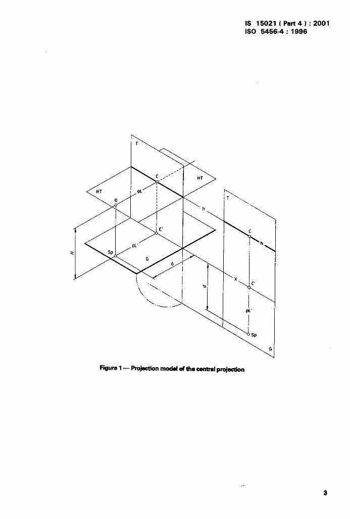
4 Symbols
Letter symbols for terms used in central projectionare given in table 1 and illustrated in figures 1 and 2,as well as in the figures mentioned in table 1.
Table 1— Lattarsymbols
No. Term Letter symbol Figura
1) Projection plane T 1
1) Basic plane G 1
1) Basic line x 1
3.4 Projection angle P 5
1) Horizon plane HT 1
1) Horizon line h 1
3.1 Alignment line VI 4
1) Main point c 11) Vanishing point v 4
1) Main projector pL 1
1) Projection centre o 13.2 Height of projection H 1
3.3 Horizontal distance d 1
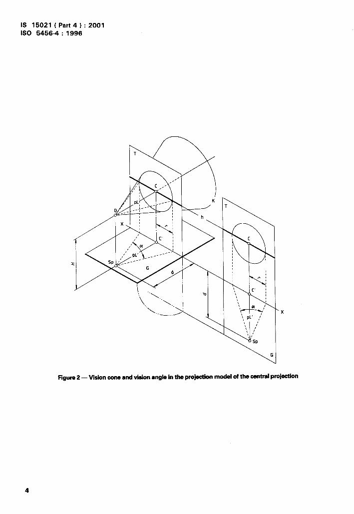
1) Vision cone K 2
1) Circle of vision Ks 3
1) Vision angle a 2
1) Projector PI 3
1) Distance point DP 13
3.5 Scale point MP 14
3.6 Station of observation Sp 1
1) Terms already defined in ISO 10209-2.
5 Centralprojectionmethods
The mode of the central projection depends on theposition of the object to be represented with respectto the projection plane.
For possible positions and applicable projectionmethods, see 5.1 to 5.4.
5.1 One-pointmethod
A one-point projection method is a central projectionof an object having its principal face parallel to theprojection plane (special position). All parallel outlinesand edges of the object which are parallel to theprojection plane retain their direction in this represen-
‘b
.,. f
.
tation (horizontal lines remain horizontal and vertical,?;<
lines remain vertical). All lines perpendicular to theprojection plane converge at the vanishing point, V,coinciding with the main point, C, (see figure 3 and7.2.1 and 7.3). . ;:
-*:$
\
,$
5.2 Two-point method%{,.,:“,
,~’A two-point projection method is a central projection .!
of an object having its vertical outlines and edges t ‘;jparaliel to the projection plane (particular position). All ,:horizontal lines of a representation converge at multi-ple vanishing points VI, V2, V3, .... on the horizon line(see figure 4 and 7.2.2 and 7.4).
5.3 Three-point method
A three-point projection method is a central projectionof an object having no outlines or edges parallel to the ;/
projection plane (any position). If the projection planeis inclined towards the projection centre, i.e. ~ >90”, 3tha vanishing point for vertical lines is situated belowthe horizon line (see figure 5 and 7.5.1 and 7.5.2).
5.4 Coordinatemethod
Representation by the coordinate method is based onsimple proportions.
The coordinates, related to the main projector of allrelevant points of the object to be represented, aretaken by the graphic method from the basic plane andelevation. From these point coordinates, the imagecoordinates are obtained by a calculation method andentered to scale. The image points are connected toeach other to provide a clear representation of theobject (see figure 6).
6 Principle
6.1 Locationandpositionoftheprojectionplane
The image size of an object can be varied by parallelshifting of the projection plane. If the object is placedin front of the projection plane, the representation willbe enlarged. The object behind the projection planewill result in a smaller image. Figure 7 shows thechange in image size depending on the position of theobject with respect to the projection plane.
Figure 8 shows the change in image size dependingon the method of representation with vertical orinclined projection planes. /3 is the included anglebetween the projection plane and the basic plane nearthe projection centre.
2
IS 15021 ( Part 4 ) :2001ISO 54564:1996
Figure1— Projectionmodal of the centralprojection
IS 15021 ( Part4 ) :2001ISO 5456-4:1996
x
Figure2 — Wion coneand viaionanglein the projectionmodal of the centralprojection
I

&—
IS 15021 ( Part 4 ) :2001ISO 5456-4:1996
‘.,
Figure 3 — Projection model with vertical projection plane and an object in a special position
with respectto the projectionplane
..
Figure4 — Projectionmodel with verticalprojectionplaneand an objectin a particularpositionwith respectto the projectionplane

IS 15021 ( Part4 ) :2001ISO 5456-4:1996
i
Figure5 — Projectionmodel with inclinedprojectionplane and an objectin any positionwith respectto the projectionplane (/3>90°)

IS 15021 ( Part4 ) :2001ISO 5456-4:1996
Figure6 — Projectionmodel with verticalprojectionplaneand an objectin specialposition,showing thelengthsused in the mathematicalformula for calculationof the parepectiveimage
P=~OtPl>wO; J%c900Figure7 — Locationof projectionplanes Figure8 — Positionof projectionplanes

IS 15021 ( Part 4 ) :2001ISO 5456-4: 1996
6.2 Circle of vision and vision cone instructive since length, width and height do notmatch the object’s inherent proportions (see figure 9).
To obtain a fully instructive image of an object withoutperipheral distortions on the projection plane, the An object can be depicted nearly undistorted if theobject must be positioned within a vision cone having projectors result in a bundle of rays inclined not morean aperture angle not greater than 60°. than 30° with respect to the main projector. At this
Heavy peripheral distortions occur on images outsideaperture angle the vision cone provides only a small
the circle of vision; the image does not appear fullydistortion on the projection plane.
/4T
o T
f!!u!iho‘\. “’b “ ““’””:,,!$paim#:: ::
J
[+C I
“-“-l
W ‘—..,1 ““~
@@RI I
Sp
Figure9 — Object, framed in a cube,within and outsidethe circleof vision
8

The main projector should hit the object to be de-picted in a part which is visually important, so that theobject is contained within the minimum vision cone.
6.3 Distance
Different relative distances influence the image size andits appearance. When the distance between the objectand the projection plane is fixed and the projection centreand the object lie on opposite sides of the projectionplane, increasing the distance (d) between the projectioncentre and the projection plane gives enlarged andflattened representations. When the distance (d) is fixedand the object and the projection centre lie on oppositesides of the projection plane, increasing the distance
IS 15021 ( Part 4 ) :2001 --qISO 5456-4:1996
{i,,t$
1:$
between the object and the projection plane gives rc+duced and flattened representations.
,
7 Principlesand methods of depiction1
7.1 Piercing method {f,,,
Using the piercing method, the piercing points ofprojectors with the projection plane are shown bybasic plane and elevation, and may be determinedeither by drawing or by calculation (see figure 10).
The piercing method allows even complex objects(round shapes, helicoids, etc.) to be easily repre-sented in central projection.
h
. .
Figure10— projectionmodal turned intothe drawingsurfacewith sideview
9
IS 15021 ( Part 4 ) :2001ISO 5456-4:1996
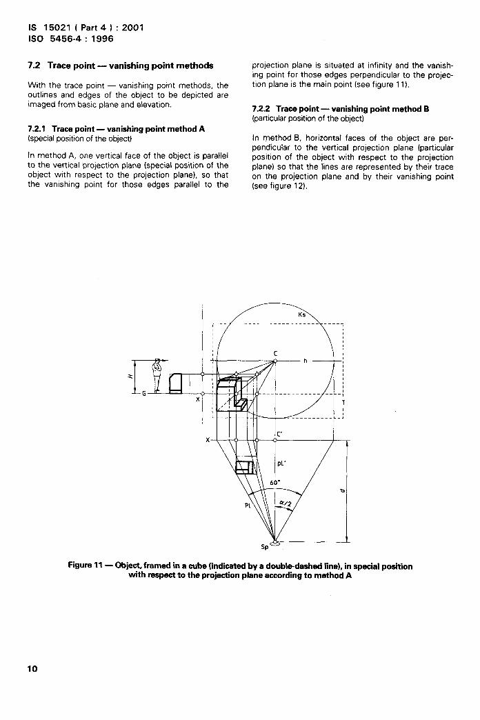
7.2 Trace point — vanishing point methods
With the trace point — vanishing point methods, theoutlines and edges of the object to be depicted areimaged from basic plane and elevation.
7.2.1 Tracepoint— vanishingpoint method A(special position of the object)
In method A, one vertical face of the object is parallelto the vertical projection plane (special position of theobject with respect to the projection plane), so thatthe vanishing point for those edges parallel to the
projection plane is situated at infinity and the vanish-ing point for those edges perpendicular to the projec-tion plane is the main point (see figure 11).
7.2.2 Tracepoint — vanishingpoint method B(particular position of the object)
In method B, horizontal faces of the object are per-pendicular to the vertical projection plane (particularposition of the object with respect to the projectionplane) so that the lines are represented by their traceon the projection plane and by their vanishing point(see figure 12).
I :---~...1( c M
z ,, $a/ /1;‘G ,
x ; ,-
-“” 1’T
.-_ ——____— _ _,
~--_ f_--f_;--./.f_;
m =1
P1 u/2
Sp
,
Figure11— Object,framed in a cube(indicatedby a double-dashedline),in specialpositionwith respectto the projectionplaneaccordingto method A
10

IS 15021 ( Part 4 ) :2001ISO 5456-4:1996
I
..?..’jZ$,..:,<
,x,,~
‘{
..
..
.
.
Figure12— Object,fremed in a cube (indicatedby a doubl~dashed line),in particularpositionwith respectto the projectionplaneaccordingto method B
11

IS 15021 ( Part4 ) :2001ISO 5456-4:1996
7.3 Distance point method tion). The distance point has the same distance from
(special position of the object) the main point as the projection centre from theprojection plane. All horizontal lines inclined at 45°
The distance point method gives the central projection with respect to the projection plane align to the dis-of an object without its basic plane, by setting up a tance point. The vanishing point of the depth lines ofperspective grid. The outlines and edges are parallel the grid is the main point (see figure 13).or perpendicular to the projection plane (special posi-
Figure13— Obje@ framed in a cube(indicatedby a double.dashedline),in specialpositionwith respectto the projectionplane

IS 15021 ( Part 4 ) :2001ISO 5456-4:1996
7.4 Scale point method of the object to be depicted may be transferred from(particular position of the object) the basic line in the projection plane on depth lines
(see figure 14). By means of the basic plane, a definiteFor any vanishing point there is a corresponding scale relation between the perspective representation ofpoint. With the aid of scale points, certain dimensions the object and the object itself may be established.
,-
Figure 14— Object,framed in a cube(indicatedby a double-dashedline),in particularpositionwith respectto the projectionplane
13

kt<
IS 15021 ( Part4 ) :2001ISO 5456-4:1996
7.5 Trace point method with inclined the vertical lines of the object to be depicted moves
projection plane from infinite to finite. The angle /3, i.e. the angle ofinclinatiorl of the projection plane with respect to the
7.5.1 Inclinedprojectionplane~ c 9Q” ‘horizon plane, defines the position of the vanishingpoint above the horizon. Vertical object lines are
Due to the inclination of the projection plane with represented as tilting lines, which gives an optical dis-respect to the horizon plane, the vanishing point for tortion suggesting a tapering form (see figure 15).
/ A!
kmI
II
\ 1 h
vi-
Sp
?7v’
/
(
0
—
Fi-gura15— Object,framed in a cube(indicatedby a double-dashed line),in front of a projection
.,
plane inclinedtowardsthe projectioncentre
14
I

4,,
IS 15021 ( Part4 ) :2001ISO 5456-4:1996
7.5.2 Inclinedprojectionplane~> 90° to be depicted moves below the horizon line frominfinite to finite, so that tilting projected vertical lines
Due to the inclination away from the projection cen- provide an optical distortion suggesting a taperingtre, the vanishing point for vertical lines of the object form (see figure 16).
P-1v \
v, \
\
J\\
Sp
3c“
--------
/
\
/
./
l-h v 0
/
/
‘\,..-/.”
v’
$2’//
—
..
Figure16— Object,framed in a cube (indicatedby a double-dashedline),in front of a projectionplane inclinedaway from the projectioncentre
15

IS 15021 ( Part4 ) :2001ISO 5456-4:1996
7.6 Coordinate piercing method
The coordinate piercing method is based on simpleproportions, in which each piercing point of the pro-jectors in the projection plane is not established bydrawing, but by calculation. This method is based ondividing the space in four quadrants by two referenceplanes, one horizontal and one vertical, each perpen-dicular to the projection plane, their common linebeing the main projector. The common lines of thehorizontal and vertical reference planes and the pro-jection plane are the X and Y axes of a rectangularCartesian coordinate system situated in the projectionplane, the origin of which is the main point. The
projector &P of point P pierces the projection plane at
point P’ (X n.
The coordinates X and Y of the point P’ can be deter-
mined from the distances ~ = BIC1 and
~ = AIC1 of the point P from the reference planes,
from the object distance D = ~ and the distance
d=~:
X= BICI. dD and Y= AICI. dD
The values calculated for X and Y for all points of the
object to be represented are transferred into thecoordinate system to obtain the representation of theobject. The dimensions needed for the calculation of
~, AICI and D are taken from the basic plane,
elevation, side view, etc. of the object, whereby theseplanes may be drawn in various scales. The represen-tation may be reduced or enlarged in a similar modeby multiplying the coordinates X and Y by the scale
factor (see figure 17).
NOTE 1 R is positive (negative) when BI is on the right
(left) side of the main projector; ~ is positive (negative)
when Al is above (below) the main projector.
8 Developmentof a centralprojection
By turning the basic plane into the projection plane(see figure 1), it is possible to present the represen-tation of the basic plane on the drawing surface andsubsequently to create the complete representationof the dimensions taken from the elevation.
There are two different ways to turn the basic plane:
.>“.
Figure17— Coordinatepiercingmethod
16
IS 15021 ( Part4 ) :2001ISO 5456-4:1996
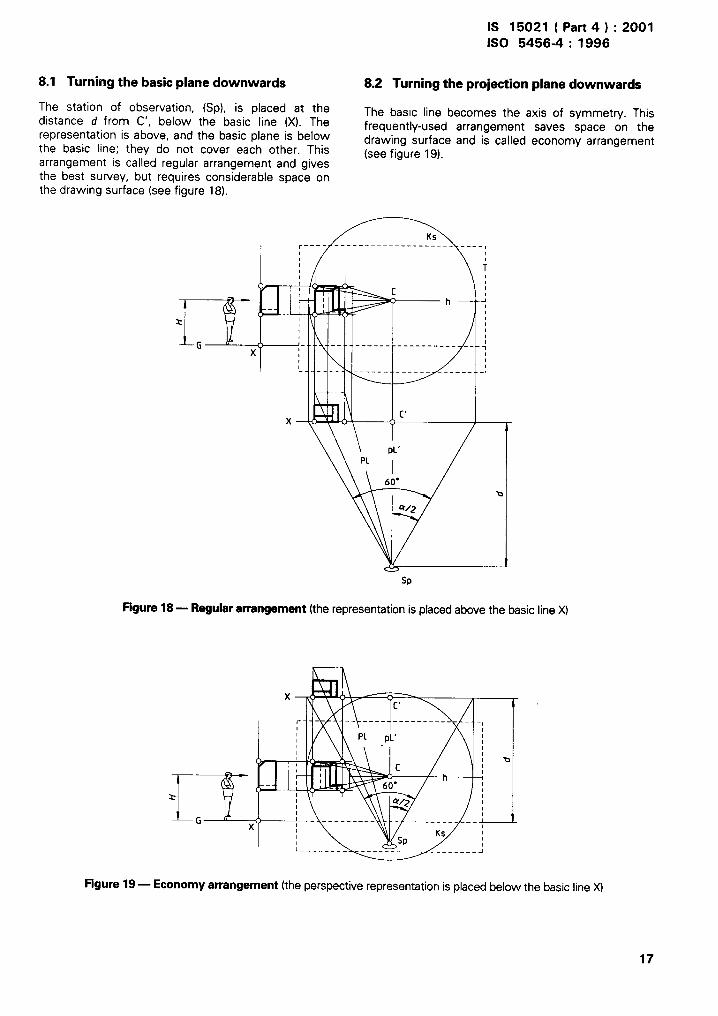
8.1 Turning the basic plane downwards 8.2 Turning the projection plane downwards
The station of observation, (Sp), is placed at thedistance d from C’, below the basic line (X). The
The basic line becomes the axis of symmetry. Thisfrequently-used arrangement saves space on the
representation is above, and the basic plane is below drawing surface and is called economy arrangementthe basic line; they do not cover each other. This (see figure 19).arrangement is cal!ed regular arrangement and givesthe best survey, but requires considerable space onthe drawing surface (see figure 18).
$,,L-,
x
i
“1’’__t’x
\lPL’
P1
\ 6i”
Ks,—.._– ------ ——— ——_________ ____l
I
i
I!iiiia -!
ch -+,1
J- -- ------ ---------- __ -;
---- -————— —1
Y/z-.-l-e
Q/2
Sp
Figure18— Regulararrangement(the representation is placed above the basic line X)
-..
Figure19— Economyarrangement(the perspective representation is placed below the basic line X)
17

a
IS 15021 ( Part 4 ) :2001ISO 5456-4: 1996
Annex A(informative)
Examples for comparison of different depiction methods
The following figures A.1 to A.17 illustrate some of the different depiction methods described in clause 7.
II
I1
1
[ I
~ _—------ .
— -
/---- -
I
.:
m
Figure A.1— Exteriorspaceimage,projectionwith one vanishingpoint the spiralstaircasehas beenrepresentadaccordingto the method describedin 7.1
18
. &
IS 15021 ( Part 4 ) :2001ISO 5456-4:1996
...-
.t
.
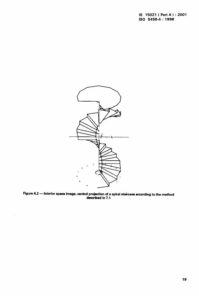
Figure A.2 — Interiorspaceimage,centralprojectionof a spiralstaircaseaccordingto the methoddescribedin 7.1
19

IS 15021 ( Part 4 ) :2001ISO 5456-4:1996
—
‘/’.
\\\
-n\
FigureA.3— Outsideinteriorspaceimage,projectionwith one vanishing point
IS 15021 ( Part4 ) :2001ISO 5456-4:1996
=+lIlllu E!I I
.-
.
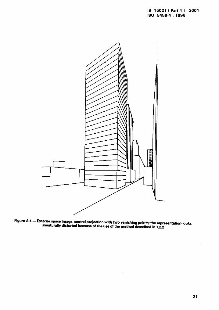
FigureA.4 — Exteriorspaceimage, centralprojectionwith two vanishingpoints; the representationlooksunnaturallydistotied becauseof the use of the method describedin 7.2.2
21

IS 15021 ( Part 4 ) :2001
ISO 5456-4: 1996
Figure A.5 — Exterior space image, projection with inclined projection plane and three vanishing points
according to the method described in 7.5.1
,
22

IS 15021 ( Part 4 ) :2001ISO 5456-4:1996
Figure A.6 — Interior space image, projedion according to the method described in 7.2 with various
vanishing points and the representation of inclined planes
?
t
Figure A.7 — Interior space image, so-called section perspective with one vanishing point
23

IS 15021 ( Part4 ) :2001ISO 5456-4:1996
I1’
J==w--- , ,/ ,
FigureA.8 — Interiorspaceimage,projectionwith one vanishingpoint and othervanishing pointafor inclinedplanes(staircases)
24

IS 15021 ( Part 4 ) :2001ISO 54564:1996
,.
FigureA.9 — Interiorspaceimage,projectionwith inclinedprojectionplaneand threevanishingpointaaccordingto tha methoddescribedin 7.5.2
25

IS 15021 ( Part 4 I :2001ISO 5456-4:1996
II
FigureA.1O— Exteriorspaceimage,projectionaccordingto the method describedin 7.6(simple wire frame model and two vanishing points)
26

IS 15021 ( Part 4 ) :2001
ISO 5456-4: 1996
FigureA.11— Exteriorepaceimage,projectioneccordingto the method deecribedin 7.6(wire frame model with further detail elaboration and OWOvanishingpoints)
/
27

IS 15021 ( Part 4 ) :2001ISO 5456-4:1996
.,+
.,!-,/
!.
FigureA.12— Exteriorapaceimage,enlargeddetailfrom figureA.11
28

IS 15021 ( Part4 ) :2001ISO 5456-4:1996
FigureA.13— Exteriorspaceimagaw-kitthe rapraaantationof surroundings,projectionwith inclinedprojectionplaneand vanishingpointaaccordingto the method describedin 7.5.3
A~
.-g
‘-..+-!
“?“~
,
.
29
I

IS 15021 ( Part 4 ) :2001ISO 5456-4:1996
&c!z! 43
l!% l!9-a) Orthogonal Images
b) Projectionwithinclinedprojectionplone
FigureA.14— Exteriorspaceimage, representationof surroundingsand accassoriee

,A,
IS 15021 ( Part4) :2001ISO 54564:1996
FiguraA.15— Exteriorapaceimageof a residentialsite,projectionwith threevanishingpoints
Figure A.16 — Extarior spaceimage(bird’seyaview),projectionwith inclinedprojectionplane
31

IS 15021 ( Part 4 ) :2001ISO 5456-4:1996
Figure A.17— Examplaof dimatricaxonomatry,rapraaantstionof an enginecrankshaft
32
I
/“

IS 15021 ( Part 4 ) :2001ISO 5456-4:1996
Annex B(informative)
Bibliography
[1] ISO 841:1974, Numerical control of machines — [51 ISO 5456-3:1996, Technical drawings — Projec-Axis and motion nomenclature. , tion methods — Part 3: Axonometric represen-
tations.[2] ISO 1503; 197’7, Geometric/ orientation and
directions of movements. [61 ISO 10208-1:1992, Technical product documen-tation — Vocabulary — Part 1: Terms relating
[31 ISO 5456-1:1996, Technics/ drawings — Projec- to technical dra wings: general and types of draw-
tion methods — Part 1: Synopsis. ings.
[4] ISO 5456-2:1996, Technical drawings — Projec-tion methods — Part 2: Orthographic represen-tations.
33

Bureau of Indian Standards
61S is a statutory institution established under the Bureau of hdian Standards Act, 1986 to promoteharmonious development of the activities of standardization, marking and quality certification of goodsand attending to connected matters in the country.
Copyright
61S has the copyright of all its publications. No part of these publications may be reproduced in anyform without the prior permission in writing of 61S. This does not preclude the free use, in the courseof implementing the standard, of necessary details, such as symbols and sizes, type or gradedesignations. Enquiries relating to copyright be addressed to the Director (Publications), 61S.
Review of Indian Standards
Amendments are issued to standards as the need arises on the basis of comments. Standards arealso reviewed periodically; a standard along with amendments is reaffirmed when such review incfi-cates that no changes are needed; if the review indicates that changes are needed, it is taken up forrevision. Users of Indian Standards should ascertain that they are in possession of the latest amend-ments or edition by referring to the latest issue of ’61S Catalogue’ and ‘Standards: Monthly Additions’.
This Indian Standard has been developed from Doc : No. BP 24 (0143).
Amendments Issued Since Publication
Amend No. Date of Issue Text Affected
BUREAU OF INDIAN STANDARDS
Headquarters :
Manak Bhavan, 9 Bahadur Shah Zafar Marg, New Delhi 110002 Telegrams : ManaksansthaTelephones :3230131,3233375, 3239402 (Common to all offices)
Regional Offices : Telephone
Central :
Eastern :
Northern :
Southern :
Western :
Branches :
Manak Bhavan, 9 Bahadur Shah Zafar Marg
{
3237617NEW DELHI 110002 3233841
1/1 4 C.I.T. Scheme WI M, V. 1.P. Road, Kankurgachi
{
3378499,3378561KOLKATA 700054 3378626,3379120
SCO 335-336, Sector 34-A, CHANDIGARH 160022
{
603843602025
C.I.T. Campus, IV Cross Road, CHENNAI 600113
{
2541216,25414422542519,2541315
Manakalaya, E9 MlDC, Marol, Andheri (East)
{
8329295,8327858MUMBAI 400093 8327891, 8327892
AHMEDABAD. BANGALORE. BHOPAL. BHUBANESHWAR. COIMBATORE.FARIDABAD. GHAZIABAD. GUWAHATI. HYDERABAD. JAIPUR. KANPUR.LUCKNOW. NAGPUR. NALAGARH. PATNA. PUNE. RAJKOT. THIRUVANANTHAPURAM.
Printed at Prabhat Offset Press, New Delhi-2
,