is 15369 (2003): code of practice for construction of
TRANSCRIPT

Disclosure to Promote the Right To Information
Whereas the Parliament of India has set out to provide a practical regime of right to information for citizens to secure access to information under the control of public authorities, in order to promote transparency and accountability in the working of every public authority, and whereas the attached publication of the Bureau of Indian Standards is of particular interest to the public, particularly disadvantaged communities and those engaged in the pursuit of education and knowledge, the attached public safety standard is made available to promote the timely dissemination of this information in an accurate manner to the public.
इंटरनेट मानक
“!ान $ एक न' भारत का +नम-ण”Satyanarayan Gangaram Pitroda
“Invent a New India Using Knowledge”
“प0रा1 को छोड न' 5 तरफ”Jawaharlal Nehru
“Step Out From the Old to the New”
“जान1 का अ+धकार, जी1 का अ+धकार”Mazdoor Kisan Shakti Sangathan
“The Right to Information, The Right to Live”
“!ान एक ऐसा खजाना > जो कभी च0राया नहB जा सकता है”Bhartṛhari—Nītiśatakam
“Knowledge is such a treasure which cannot be stolen”
“Invent a New India Using Knowledge”
है”ह”ह
IS 15369 (2003): Code of Practice for Construction ofValult (Strong-Room) [MED 24: Mechanical Engineering]


IS 15369 : 2003 (Reaffiremed 2008)
Indian Standard CODE OF PRACTICE FOR
CONSTRUCTION OF VAULT (STRONG-ROOM)
ICS 13.310
© BIS 2003
B U R E A U O F I N D I A N S T A N D A R D S MANAK BHAVAN, 9 BAHADUR SHAH ZAFAR MARG
NEW DELHI 110002
July 2003 Price Group 4

Security Equipment Sectional Committee, ME 24
FOREWORD
This Indian Standard was adopted by the Bureau of Indian Standards, after the draft finalized by the Security Equipment Sectional Committee had been approved by the Mechanical Engineering Division Council.
Vault (strong-room) play a very important role in protecting cash, jewellery and other valuables against the threat of burglary attacks and fire. While equipments like safes, lockers and record protection cabinets protect the contents to a certain degree of security, the vault protects this equipment and enhances the degree of security to the contents of these equipments. Thus, vault is a peripheral security arrangement, which is a must, where the risk levels are high.
IS 11188 (Part 1) : 1991 'Vault (strong-room) doors: Part 1 Specification (first revision)' specifies five classes of vault doors in the increasing degree of security levels. The vaults are also classified in five increasing levels of security, which will be compatible with the five classes of doors. This will provide meaningful quantum jump in the security offered by vaults for the benefit and choice of user. The recommended use of vault and the door to be fitted is a general guideline to user. This is because finally the external conditions such as remote location, rare/frequent policing; normal or terrorist hit area, as also the amount of wealth to be protected shall define the exact risk level. The selection of vault and the door to be fitted shall, therefore be best decided by the user after assessing actual risk level.
The composition of the Committee responsible for the formulation of this standard is given in Annex B.

AMENDMENT NO. 1 DECEMBER 2004 TO
IS 15369 : 2003 CODE OF PRACTICE FOR CONSTRUCTION OF VAULT (STRONG-ROOM) ( Page 3, Fig. 2) — Substitute the following for the existing figure:
ENLARGED DETAIL AT - A All dimensions in millimetres.
FIG. 2 TYPICAL UNTWISTED FORM OF TANG BAR
1

Amend No. 1 to IS 15369 : 2003
( Page 5, clause 8.1, sixteenth line ) — Substitute 'minimum 3.5 mm taper per tooth' for '3.5 mm taper per tooth'.
( Page 5, clause 8.1, last line ) — Substitute the words 'twisted tang bar' for 'listed long bar'.
(ME 24) Reprography Unit, BIS, New Delhi, India
2
IS 15369 : 2003
Indian Standard CODE OF PRACTICE FOR
CONSTRUCTION OF VAULT (STRONG-ROOM) 1 SCOPE This standard lays down the requirements regarding sizes, materials, and details of construction of various classes of vault and their recommended use.
2 REFERENCES The standards listed in Annex A contain provisions, which through reference in this text constitute provisions of this standard. At the time of publication, the editions indicated were valid. All standards are subject to revision, and parties to agreements based on this standard are encouraged to investigate the possibility of applying the most recent editions of the standards indicated in Annex A.
3 CLASSIFICATION AND RECOMMENDED USE The vaults shall be of five classes. The recommended use and door to be installed shall be as per Table 1.
4 SIZES The vault sizes shall be denoted by their internal clear dimensions as specified in Table 1.
5 DESIGNATION Vault shall generally be designated by its class, the number of this Indian Standard and size, wherever applicable.
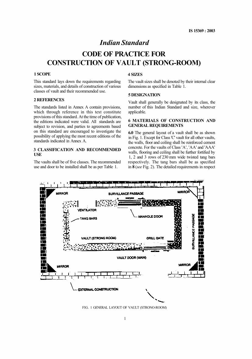
6 MATERIALS OF CONSTRUCTION AND GENERAL REQUIREMENTS 6.0 The general layout of a vault shall be as shown in Fig. 1. Except for Class 'C' vault for all other vaults, the walls, floor and ceiling shall be reinforced cement concrete. For the vaults of Class 'A', 'AA' and 'AAA' walls, flooring and ceiling shall be further fortified by 1, 2 and 3 rows of 230 mm wide twisted tang bars respectively. The tang bars shall be as specified in 8 (see Fig. 2). The detailed requirements in respect
FIG. 1 GENERAL LAYOUT OF VAULT (STRONO-ROOM)
1

IS 15369 : 2003
of each class shall be as given in 6.1, 6.2, 6.3, 6.4 and 6.5.
6.1 Class 'C' Vault 6.1.1 The Class 'C' vault is of portable type and shall be constructed from mild steel plates lined with high quality fire resisting insulation blocks/bricks [see 3, 4, 8 and 9 of IS 2185 (Part 3)].
6.1.2 All six sides of the Class 'C' vault shall be made from minimum 10 mm thick mild steel plates of any of the grades given in 4 conforming to the requirements given in 6 (C and Mn only), 7.3, 8 and 12 of IS 1079 or any of the grades given in 5 conforming to the requirements given in 8 (C and Mn only), 10.3 and 11 of IS 2062 or of any of the grades given in 6 conforming to the requirements given in 7 (C and Mn only), 9.3 and 10 of IS 5986 (see also IS 1730). The plates shall be connected to each other by minimum 10 nun bolts or counter sunk screws at pitch not exceeding 200 mm center to center. The joining
method shall be such that the bolts or counter sunk screws [see 3 of IS 1364 (Parts 1 and 3)or 2 of IS 1365] are not traceable when viewed externally or accessible from outside. The thickness of joining member made of mild steel shall not be less than 10 mm.
6.1 3 All steel plates and structurals shall be shot blasted/chemically cleaned to remove rust, scale, grease, etc, to provide proper surface for application of further anti-corrosive protecting layer. The finishing shall be by minimum one coat of anti-corrosive primer followed by final finish in enamel paint (see 3.4 of IS 110 and 5.5 of IS 133 or 6.5 of IS 2932) or nitrocellulose paint (see 3.4 of IS 6126) or alkyd amino paint (see 4.1 of IS 11811) after assembly at site.
6.1.4 Except for door area, the entire Class 'C' vault shall be covered with quality fire resisting blocks/bricks conforming to 3, 4, 8 and 9 of IS 2185 (Part 3) on all four sides and complete ceiling. The total protection of bricks/blocks shall be minimum 230 mm thick for sides and minimum 150 mm thick for ceiling.
Table 1 Classification of Vaults (Clauses 3 and 4)
All dimensions in millimetres.
Vault Class
Recommended application
Recommended main door, emergency door [ see
IS 11188 (Part 1)]
Recommended internal clear usable size without obstruction (H ×W × D)
Construction
Surveillance passage
Ventilator
Wealth level
Risk level
—
Tolerance on dimensions: ±2
percent
Wall thickness
Floor and roof
Concrete mix (see IS 456)
Steel
grid
Bar dia.
Mesh
Tang bars, Min
Height from ground level
C Low
Low
Class 'C'
2450 × 3350 × 2450
2450 × 4575 × 2450
2 450 × 4 575 × 4 880
Portable mild steel plate with fire resistance
insulation
600, Min for 'back and sides'
—
B Medium
Low
Class 'B'
As required by the user
300, Min
300, Min
1420, Min
12 150 × 150 × 150
CTC
Not
mandatory
A Medium
Medium
Class 'A'
As required by the user
450, Min
300. Min
M20, Min
16 200 × 200 ×
200
CTC
1 Row
AA Medium
High
Class 'AA'
As required by the user
450, Min
450, Min
M20, Min
16 200 × 200 ×
200
CTC
2 Rows
AAA High
High
Class 'AAA'
As required by the user
600. Min
600, Min
M25, Min
16 200 × 200 ×
200
CTC
3 Rows
1 150, Min for 'front and back', 760, Min for 'sides'
2 100, Min
2

IS 15369 : 2003
ENLARGED DETAIL AT - A FIG. 2 TYPICAL UNTWISTED FORM OF TANG BAR
6.1.5 Surveillance
There must be a surveillance space of minimum 600 mm wide between Class 'C' vault and the outside construction and the same shall be accessible to the guards on duty on all sides except for the passage connecting the vault door to the external door where the passage shall be wide to permit maneuvering of the trolleys. Class 'C' vault shall be fitted with Class 'C' main door as per 5, 7, 8 and 13 of IS 11188 (Part 1).
6.1.6 Recommended standard minimum clear internal sizes for Class 'C' vault are 2 450 mm height × 3 350 mm width × 2 450 mm depth. If required by purchaser, the sizes can vary to suit the available space.
6.2 Class 'B' Vault 6.2.1 Walls
Walls of the Class 'B' vault shall be of reinforced concrete of grade minimum M 20 as per 6 and 9.2 of IS 456 and shall be of minimum thickness 300 mm. The reinforcement shall be of mild steel rods of minimum 12 mm diameter (see 7 and 8 of IS 9550 and 4 of IS 1732) placed vertically and horizontally at 150 mm center to center distance to form mesh and two meshes shall be staggered apart in such a way so
that the reinforcement bars shall be at every 75 mm center to center in cross section.
6.2.2 Floor and Roof
Floor and roof shall be reinforced concrete of grade minimum M 20 as per 6 and 9.2 of IS 456 and of minimum 300 mm thickness. The reinforcement shall be of minimum 12 mm diameter mild steel rods (see 7 and 8 of IS 9550 and 4 of IS 1732) placed both ways at 150 mm center to center to form mesh. The number and diameter of rods shall vary if the span and thickness of floor is increased. This is in addition to the normal structural reinforcement required for the roof and floor as the design and the users of these specifications are encouraged to consult a qualified structural consultant for designing the structure namely roof, walls, floors, etc.
6.2.3 Main Door
The recommended door for Class 'B' vault is Class 'B' main door as per IS 11188 (Part I).
6.2.4 Emergency Door
The recommended emergency door for Class 'B' vault shall be of identical security level as the main door, namely Class 'B' emergency door as per IS 11188 (Part I).
3

IS 15369 : 2003
6.2.5 Surveillance The surveillance space of minimum 760 mm width shall be kept on all sides around the Class 'B' if, the premise around the vault is not under users possession. 6.2.6 Ventilation
If required ventilator shall be provided as per IS 14387 and placed high enough on the wall for efficient ventilation. Alternatively emergency door given in 6.2.4 along with plenum chamber attachment may be used for ventilation.
6.3 Class 'A' Vault 6.3.1 Walls
Walls of the Class 'A' vault shall be of reinforced concrete of grade minimum M 20 as per 6 and 9.2 of IS 456 and of minimum 450 mm thickness. The reinforcement shall be of mild steel rods of minimum 16 mm diameter (see 7 and 8 of IS 9550 and 4 of IS 1732) placed vertically and horizontally at 200 mm center-to-center distance to form mesh and two meshes shall be staggered in such a way so that the reinforcement bars shall be at every 100 mm in cross-section. The walls shall be further fortified with nominal 230 mm wide × 3.15 mm thick twisted tang bars (see 8) in single row. 6.3.2 Floor and Roof
Floor and roof shall be reinforced concrete of M 20 as per 6 and 9.2 of IS 456 and of minimum 300 mm thickness. The reinforcement shall be of same structure as of wall, namely two way doubly reinforcement with 16 mm diameter mild steel rods (see 7 and 8 of IS 9550 and 4 of IS 1732) with staggered arrangement and single row of tang bars.
6.3.3 Main Door
The recommended door for Class 'A' vault is Class 'A' main door as per IS 11188 (Part 1).
6.3.4 Emergency Door
The recommended emergency door for Class 'A' vault shall be of identical security level as the main door, namely Class 'A' emergency door as per IS 11188 (Part 1).
6.3.5 Surveillance
The surveillance space of minimum 760 mm width shall be kept on all sides around the Class 'A' vault if the premises around the vault are not under user possession. The passage space on the side where main door is provided shall be widened to permit maneuvering of the trolleys. 6.3.6 Ventilation
If required, ventilator shall be provided as per IS 14387
and placed high enough on the wall for efficient ventilation. Alternatively, emergency door given in 6.3.4 along with plenum chamber attachment may be used for ventilation.
6.4 'Class AA' Vault 6.4.1 Walls
Walls of the Class 'AA' vault shall be of reinforced concrete of grade minimum M 20 as per 6 and 9.2 of IS 456 and minimum 450 mm thick. The reinforcement shall be of mild steel rods of minimum 16 mm diameter (see 7 and 8 of IS 9550 and 4 of IS 1732) placed vertically and horizontally at 200 mm center-to-center distance to form mesh and two meshes shall be staggered in such a way so that the reinforcement bars shall be at every 100 mm in cross-section. The remforcement shall be further fortified with 230 mm wide × 3.15 mm thick twisted tang bars (see 8) in two rows.
6.4.2 Floor and Roof
Floor and roof shall be reinforced concrete of grade minimum M 20 as per 6 and 9.2 of IS 456 and minimum 450 mm thick. The reinforcement shall be of same structure as of wall, namely two way doubly reinforcement with 16 mm diameter mild steel rods (see 7 and 8 of IS 9550 and 4 of IS 1732) and two rows of twisted tang bars.
6.4.3 Main Door
The recommended door for Class 'AA' vault is Class 'AA' main door as per IS 11188 (Part 1).
6.4.4 Emergency Door
The recommended emergency door for Class 'AA' vault shall be of identical security level as the main door, namely Class 'AA' emergency door as per IS 11188 (Part 1).
6.4.5 Surveillance
The surveillance space of 760 mm wide around the Class 'AA' vault shall be kept. The passage space on the side where main door is provided shall be widened to permit maneuvering of the trolleys.
6.4.6 Ventilation
If required may be provided with plenum chamber attachment to the emergency door as given in 6.4.4 for ventilation.
6.5 Class 'AAA' Vault
6.5.1 Walls
Walls of the Class 'AAA' vault shall be of reinforced concrete of grade M25 as per 6 and 9.2 of IS 456 and minimum of 600 nun thick. The reinforcement shall
4

IS 15369 : 2003
be of mild steel rods of minimum 16 mm diameter (see 7 and 8 of IS 9550 and 4 of IS 1732) placed vertically and horizontally at 200 mm center distance staggered to form mesh and two meshes shall be in such a way so that the reinforcement bars shall be at every 100 mm in cross-section. The reinforcement shall be further fortified with 230 mm wide × 3.15 mm thick twisted tang bars (see 8 for further details of tang bars) in three rows. 6.5.2 Floor and Roof
Floor and roof shall be reinforced concrete of grade M 25 as per 6 and 9.2 of IS 456 and minimum 600 mm thick. The reinforcement shall be of same structure as of wall, namely two way doubly reinforcement with 16 mm diameter mild steel rods (see 7 and 8 of IS 9550 and 4 of IS 1732) with staggered arrangement and three rows of twisted tang bars.
6.5.3 Main Door
The recommended door for Class 'AAA' vault is class 'AAA' main door as per IS 11188 (Part 1).
6.5.4 Emergency Door
The recommended emergency door for Class 'AAA' vault shall be of identical security level as the main door, namely Class 'AAA' emergency door as per IS 11188 (Part 1). 6.5.5 Surveillance
The surveillance space of 760 mm wide around the Class 'AAA' vault shall be kept. The passage space on the side where main door is provided shall be widened to permit maneuvering of the trolleys.
6.5.6 Ventilation
If required may be provided with plenum chamber attachment to the emergency door as given in 6.5.4.
7 WIRING ARRANGEMENT INSIDE VAULT
All electrical wiring inside vault shall be as per the best safety standards. The power inside vault shall preferably be controlled by power cut-off switch provided on vault door. The arrangement shall preferably be such that when the external door is closed, the power inside vault shall get cut off automatically [see 9.4 of IS 11188 (Part 1)].
8 TANG BAR — DESIGN AND CONSTRUCTION DETAILS
8.1 Design Tang bar shall be made from 230 mm wide and 3.15 mm nominal thickness steel sheet of any of the four grades given in 3 conforming to the requirements given in 6 and 7.4 of IS 513 or any of the grades given in 4 conforming to the requirements given in 6 (C and Mn only), 7.3, 8 and 12 of IS 1079 or any of the grades given in 5 conforming to the requirements given in 8 (C and Mn only), 10.3 and 11 of IS 2062 or any of the grades given in 6 conforming to the requirements given in 7 (C and Mn only), 9.3 and 10 of IS 5986 (see also IS 1730) and shall be stamped in the form of a double comb for maximum material utilization (see Fig. 2). The tangs of the tang bar shall have tapered shape to resist the pulling attempt of tang bar from partially attacked concrete wall. The amount of taper to be included is 3.5 mm taper per tooth. Tang bar before laying down on site shall be twisted by a tang bar twisting machine, to radiate the tangs in all directions. The number of twists of 180° each shall be approximately 2 per running meter length of tang bar. A typical form of listed long bar is given in Fig. 3.
8.2 Welded Tang Bar 8.2.1 When stamped from full sheet, the first and last strip of tang bars shall have tangs in one direction only. Two end strips of tang bars may be welded by manual metal arc welding or any other superior process like CO2 welding, MIG welding etc. with each other to have one full tang bar having tangs in both directions. The percentage of welded tang bars to be used in a given wall shall be limited to a maximum of 7.5 percent subject to agreement by the purchaser.
8.2.2 A typical welded flat tang bar construction is shown in Fig. 4.
8.3 Laying of Tang Bars Tangs bar shall be laid in such a way that each tang bar shall overlap by minimum 25 mm along the length. When laid in double or triple rows the overlap shall be minimum 25 mm across the row. Further the overlapping joints (along the length) shall be staggered
FIG. 3 TYPICAL TWISTED FORM OF TANG BAR
5

IS 15369 : 2003
All dimensions in millimetres.
FIG. 4 TYPICAL WELDED TANG BAR
in successive layer (like brickwork) to avoid weak section.
While laying the tang bars, it is essential that the method adopted does not impair the efficiency of the
structural reinforcement. The precise procedure may require variation to suit individual jobs and may call for the advice of the Architect or Structural Engineer.
ANNEX A (Clause 2)
LIST OF REFERRED INDIAN STANDARDS
IS No. 110 : 1983
133 : 1993
456 : 2000
513 : 1994
1079 : 1994
1364
(Part 1) : 1992
(Part 3) : 1992
1365 : 1978
1730 : 1989
Title Ready mixed paint, brushing, grey filler, for enamels, for use over primers (first revision) Enamel, interior (a) undercoating (b) finishing — Specification (third revision) Plain and reinforced concrete — Code of practice (third revision) Cold-rolled low carbon steel sheet and strip (fourth revision) Hot rolled carbon steel sheets and strips — Specification (fifth revision) Hexagonal head bolts, screws and nuts of product grades A and B: Hexagon head bolts (size range M 1.6 to M 64) (third revision) Hexagon nuts (size range M 1.6 to M 64) (third revision) Slotted counter sunk head screws (third revision) Steel plates, sheets, strips and flats for structural and general engineering purposes — Dimensions (second revision)
IS No. 1732 : 1989
2062 : 1999
2185 (Part 3): 1984
2932 : 1993
5986 : 2002
6126 : 1971 9550 : 2001 11188 (Part 1) : 1991
11811 : 1986 14387 : 1996
Title Steel bars, round and square for structural and general engineering purposes — Dimensions (first revision) Steel for general structural purposes — Specification (fifth revision) Concrete masonry units: Part 3 Autoclaved cellular (aerated) concrete blocks (first revision) Enamel, synthetic exterior (a) undercoating (b) finishing (second revision) Hot rolled steel plates, sheets, strips and flats for forging and forming operation — Specification (second revision) Nitrocellulose surfacer Bright bars (first revision) Vault (strong room) doors: Part 1 Specification (first revision) Alkyd resins Vaults — Air ventilation — Specification
6

IS 15369 : 2003
ANNEX B (Foreword)
COMMITTEE COMPOSITION Security Equipment Sectional Committee, ME 24
Organization Reserve Bank of India, Mumbai
Bank of India, Mumbai Central Bank of India, Mumbai
Central Building Research Institute, Roorkee
Central Bureau of Investigation, New Delhi
Chandan Metal Products Pvt Ltd, Vadodara
Center for Environment and Explosive Safety (DRDO), New Delhi
General Insurance Corporation of India, Mumbai
Godrej and Boyce Manufacture Co Ltd, Mumbai
Loss Prevention Association of India Ltd, New Delhi
Methodex Systems Ltd. New Delhi
Punjab National Bank, New Delhi
Standard Chartered Bank, Mumbai State Bank of India, Mumbai
Steelage Industries Ltd, Mumbai
Union Bank of India, Mumbai
BIS Directorate General
Representative (s) SHRI B . K. KATYAL (Chairman)
SHRI K. RAGHUNATHAN (Alternate)
SHRI S. HARIHARAN
M. L. KANAUJIA
SHRI D. R. SHARMA (Alternate)
DR T. P. SHARMA
SHRI SUBIR SINGH (Alternate)
DR S. R. SINGH
DR RAJINDER SINGH (Alternate)
SHRI NITIN P. PATNI
SHRI G. D. VERMA (Alternate)
SHRI A. K. KAPOOR
SHRI V. K. CHAUDHARY (Alternate)
SHRI S. M. TRIPATHI
SHRI T. R. A. KRISHNAN (Alternate)
SHRI D. E. BYRAMJEE
SHRI AJIT NIRVANE (Alternate)
SHRI D. K. SARKAR
SHRI T. P. RAO (Alternate)
COL (RETD) R. C. SARIN
SHRI SUNIL WALI (Alternate)
CAPT S. P. SINGH
SHRI K. L. JAGGA (Alternate)
SHRI ROBERT G. TAYLOR
SHRI G. V. CHANANA
SHRI S. D. SUMANI (Alternate)
SHRI SANJOY DAS
SHRI N. S. JOSHI (Alternate)
SHRI K. C. SATPATHY
CAPT E. RAJARAM (Alternate)
SHRI M. L. CHOPRA, Director & Head (MED) [Representing Director General (Ex-officio)]
Member Secretary SHRI P. VENKATESWARA RAO Joint Director (MED), BIS
7

Bureau of Indian Standards
BIS is a statutory institution established under the Bureau of Indian Standards Act, 1986 to promote harmonious development of the activities of standardization, marking and quality certification of goods and attending to connected matters in the country.
Copyright
BIS has the copyright of all its publications. No part of these publications may be reproduced in any form without the prior permission in writing of BIS. This does not preclude the free use, in the course of implementing the standard, of necessary details, such as symbols and sizes, type or grade designations. Enquiries relating to copyright be addressed to the Director (Publications), BIS.
Review of Indian Standards
Amendments are issued to standards as the need arises on the basis of comments. Standards are also reviewed periodically; a standard along with amendments is reaffirmed when such review indicates that no changes are needed; if the review indicates that changes are needed, it is taken up for revision. Users of Indian Standards should ascertain that they are in possession of the latest amendments or edition by referring to the latest issue of 'B1S Catalogue' and 'Standards: Monthly Additions'.
This Indian Standard has been developed from Doc : No. ME 24 (0504).
Amendments Issued Since Publication
Amend No. Date of Issue Text Affected
BUREAU OF INDIAN STANDARDS Headquarters : Manak Bhavan, 9 Bahadur Shah Zafar Marg, New Delhi 110 002 Telephones : 2323 0131, 2323 33 75, 2323 9402
Telegrams : Manaksanstha (Common to all offices)
Regional Offices :
Central : Manak Bhavan, 9 Bahadur Shah Zafar Marg NEW DELHI 110 002
Eastern : 1/14 C.I.T. Scheme VII M, V. I. P. Road, Kankurgachi KOLKATA 700 054
Northern : SCO 335-336, Sector 34-A, CHANDIGARH 160 022
Southern : C.I.T. Campus, IV Cross Road, CHENNAI 600 113
Western : Manakalaya, E9 MIDC, Marol, Andheri (East) MUMBAI 400 093
Telephone 2323 7617 2323 3841
'2337 8499, 2337 8561 2337 8626, 2337 9120
60 3843 60 9285
2254 1216, 2254 1442 2254 2519, 2254 2315
2832 9295, 2832 7858 2832 7891, 2832 7892
Branches : AHMEDABAD. BANGALORE. BHOPAL. BHUBANESHWAR. COIMBATORE. FARIDABAD. GHAZIABAD. GUWAHATI. HYDERABAD. JAIPUR. KANPUR. LUCKNOW. NAGPUR. NALAGARH. PATNA. PUNE. RAJKOT. THIRUVANANTHAPURAM. VISAKHAPATNAM.
Printed at Prabhat Offset Press. New Delhi-2