is 2327 (1993): straight sided splines for cylindrical shafts with … · 2018-11-14 · is 2327 :...
TRANSCRIPT

Disclosure to Promote the Right To Information
Whereas the Parliament of India has set out to provide a practical regime of right to information for citizens to secure access to information under the control of public authorities, in order to promote transparency and accountability in the working of every public authority, and whereas the attached publication of the Bureau of Indian Standards is of particular interest to the public, particularly disadvantaged communities and those engaged in the pursuit of education and knowledge, the attached public safety standard is made available to promote the timely dissemination of this information in an accurate manner to the public.
इंटरनेट मानक
“!ान $ एक न' भारत का +नम-ण”Satyanarayan Gangaram Pitroda
“Invent a New India Using Knowledge”
“प0रा1 को छोड न' 5 तरफ”Jawaharlal Nehru
“Step Out From the Old to the New”
“जान1 का अ+धकार, जी1 का अ+धकार”Mazdoor Kisan Shakti Sangathan
“The Right to Information, The Right to Live”
“!ान एक ऐसा खजाना > जो कभी च0राया नहB जा सकता है”Bhartṛhari—Nītiśatakam
“Knowledge is such a treasure which cannot be stolen”
“Invent a New India Using Knowledge”
है”ह”ह
IS 2327 (1993): Straight sided splines for cylindricalshafts with internal centering - Dimensions, tolerances andverification [PGD 31: Bolts, Nuts and FastenersAccessories]


IS 2327 : 1993 IS0 14 : 1982
Indian Standard
STRAIGHT-SIDED SPLINES FOR CYLINDRICAL SHAFTS WITH INTERNAL CENTERING -
DIMENSIONS, TOLERANCES AND VERIFICATION
( First Revision )
U DC 621’824’4
‘gl BIS 1993
BUREAU OF INDIAN STANDARDS MANAK BHAVAN, 9 BAYADUR SHAH ZAFAH b’PFG
NEW DELHI 110002
May 1993 Price Group 6
-Transmission Devices Sectional Committee, LM 10
‘NATIONAL FOREWORD
This Indian Standard ( First Revision ) which is identical with IS0 14 : 1982 ‘Straight-sided splines for cylindrical shafts with internal centering - Dimensions, tolerances and verification’, issued by the International Organization for Standardization ( IS0 ), was adopted by the Bureau of Indian Standards on the recommendation of the Transmission Devices Sectional Committee ( LM ‘IO ) and approval of the Light rVlechanical Engineering Division Council.
Splined shafts are generally used:
a) for coupling shafts when relatively heavy torques are to be transmitted without slip;
b) for transmitted power by sliding or fixed gears, pulleys and other rotating members; and
c) for attaching parts that may require removal for indexing or change in angular position.
Spline shafts and hubs have wide application in the automobile, machine tool and other indus- tries. This standard was originally published in 1963. The present revision has been taken up ta harmonize it with IS0 14 : 1982.
In the adopted standard certain terminolcgy and conventions are not identical with those used ,in the Indian Standard, attention is especially drawn to the following:
a) Comma ( , ) has been used as decimal marker while in Indian Standards, the current practice is to use a point ( . ) as the decimal marker.
b) Wherever the words ‘International Standard’ appear referring to this standard, they shall be read as ‘Indian Standard’.

IS 2327 : 1993
IS0 14 : 1982
Indian Standard
STRAIGHT-SIDED SPLINES FOR CYLINDRICAL SHAF
DIMENSI ‘TS WITH INTERNAL CENTERING - ONS, TOLERANCES AND VERIFICATION
( First Revision )
1 Scope and field of application
Thus International Standard lays down dimensions, in
millrmetres, of straight-sided splines for cylindrical shafts with
internal centering, light series and medium series.
This International Standard also specifies control methods and
corresponding gauges.
2 Dimensions
The nominal dimensions common to shaft and hub, d, D and B
are given in table 1. The tolerances are indicated in tables 2
and 3.
3 Designation
The profile of a splined shaft or hub shall be designated by
stating, in the following order : the number of splines N, the
minor diameter d and the outside diameter D, these three
numbers being separated by the sign x ; for example :
Shaft for hub) 6 x 23 x 26
Table 1 - Nominal dimensions
-
d
mm
ii
13
16
18
21
23
26
28
32
36
42
46
52
56
62
72
82
w
102
112 -
T Light series
Designation
6x 23x 26
6 x 26 x 30
6x 28x 32
8x 32x 36
8x36~40
8x 42x 46
8x46~50
8x 52x 58
8x 56x 62
8x 62x 68
10x 72x 78
10x 82x 88
10x 92x 99
10 x 102 x 108
10 x 112 x 120 L
- N
6 26
6 30
6 32
a 36
8 40
8 46
a 50
8 58
8 62
a 68
10
10
10
10
10
78
86
98
I
f
D mm
B mm
6
6
7
6x 11x 14
6 x 13 x 16
6x 16x 20
6x 18x 22
6x 21x 25
6 x 23 x 28
6 x 26 x 32
6x26x34
6 25 5
6 28 6
6 32 6
6 34 7
6 8x 32x38 8 38 6
7 8x 36x 42 8 42 7
8 8x 42x 48 8 46 8
9 8x46~54 8 54 9
10
10
12
.a 60
8 65
8 72
12
12
14
82
92
102
16
18
8x 52x 60
8x 56x 65
8 x 62 x 72
10x 72x 82
10 x 82x 92
10 x 92 x 102
10 x 102 x 112
10 x 112 x 125 I 10
10
10
fb
10
112
125
10
10
12
12
12
14
E - I
I Medium series 1 Designation
i
N
6 6
6
6
D mm
14
16
20
22
f
B mm
3
3.5
4
5
1
IS 2327 : 1993
IS0 14 : 1982
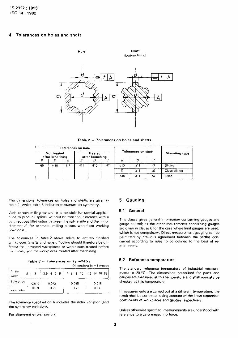
4 Tolerances on holes and shaft
4
i
Hole Shaft
(bottom fitting)
Table 2 - Tolerances on holes and shafts
-El A
I Tolerances on hole i I I
Not treated Treated Tolerances on shaft
Mounting type after broaching after broaching
B j D d B D d B D d
H9 I HlO H7 Hll HlO H7 d10 all f7 Sliding
I f9 all 97 Close sliding
h10 all h7 Fixed
The dimensional tolerances on holes and shafts are given in
table 2, whilst table 3 indicates tolerances on symmetry.
‘Ntth certain milling cutters, it is possible for special applica-
*Ions to produce splines without bottom tool clearance with a
very reduced fillet radius between the spline side and the minor
diameter d (for example, milling cutters with fixed working
oositrons).
Tne tolerances in table 2 above relate to entirely finished
‘Aorkpieces (shafts and hubs). Tooling should therefore be dif-
ferent for untreated workpieces or workpieces treated before
:mchmlng and for workpieces treated after machining.
Table 3 - Tolerances on symmetry
Dimensions in millimetres
I Spllne I
3.5 4 5 6 / 7 8 9 10 12 14 16 18 width I
--t-- I
I rolerance
of 0,010 / 0,012 0,015 0,018
i symmetry ” (IT71 (IT7) (IT7) (IT71
The tolerance specified on B includes the index variation (and
the symmetry variation).
For alignment errors, see 5.7
5 Gauging
5.1 General
This clause gives general information concerning gauges and
gauge control; all the other requirements concerning gauges
are given in clause 6 for the case where limit gauges are used,
which is not compulsory. Direct measurement gauging can be
permitted by previous agreement between the parties con-
cerned according to rules to be defined to the best of re-
quirements.
5.2 Reference temperature
The standard reference temperature of industrial measure-
ments is 20 OC. The dimensions prescribed for parts and
gauges are measured at this temperature and shall normally be
checked at this temperature.
If measurements are carried out at a different temperature, the
result shall be corrected taking account of the linear expansion
coefficients of workpieces and gauges respectively.
Unless otherwise specified, measurements are understood with
reference to a zero measuring force.
IS 2327 : 1993
IS0 14 : 1982
If mess~~rements are carried out with a measuring force differ-
ing from zero, the results shall be corrected consequently. Cor-
rection however is not required for comparative measurements
carried out using the same means of comparison and the same
measuring force between similar elements of the same material
and surface finish.
5.3 Conditions of application
A workpiece is conventionally acknowledged good when its
splines are found satisfactory using gauges according to the re-
quirements of clauses 5 and 6 of this International Standard
which are authoritative for gauging. Consequently, if the
customer uses his own gauges for acceptance purposes, they
shall be close enough to the external limits prescribed not to re-
ject splines already accepted by the manufacturer’s gauges.
In the case of dispute, both the manufacturer and customer
should make their gauges available to each other for checking
at their respective sites. In the event of continuing dispute the
gauges shall be referred to a recognized calibration authority.
5.4 Shaft gauging
5.4.1 GO side
Shaft yauglng on the GO side is carried out using a spline GO
ring gauge simultaneously checking ?hose characteristics
relating to :
5.4.1.1 fitting, i.e. :
- spllne minor diameter.
i.4.1.2 mounting, i.e. :
- spltne major diameter;
- spline thickness;
.~ major and minor diameter concentricity;
spline angular position;
- spline position ano orientation with respect to the
axis. Ii
1.2 NOT GO side
aft gauging on the NOT GO side is carned out using segmen-
NOT GO gauges checking each element separately, i.e. :
- for spline major diameters : a calliper gauge or a plain
ring gauge;
-- for spllne minor diameters : a calliper gauge (with
appropriate special anvils, if necessary);
- for spline thicknesses : a calliper gauge (of appropriate
external shape if necessary).
5.5 Hole gauging
5.5.1 GO side
Hole gauging on the GO side is carried out using a spline GO
plug gauge simultaneously checking those characteristics
relating to :
5.5.1.1 fitting, i.e :
- spline minor diameter.
5.5.1.2 mounting, i.e :
- spline major diameter;
- spline space width;
- major and minor diameter concentncrty;
- spline angular position;
- sptlne posltion and orientation with respect to the
axis. 11
5.5.2 NOT GO side
Hole gauging on the NOT GO side is carried out using NOT GO
segmental gauges checkrng each element separately, 1.e.
- for spline minor diameters : a cylindrical plain plug
gauge;
-- for spline major diameters : a cylindricai plate gauge
with appropriate measuring faces;
-- for spline space widths : a plate gauge
5.6 Additional gauging
Workprece (hole or shaft) gauging on the GO stde by means of
spline !plug or ring) gauges does not make it possible, if a
workpiece IS rejected by the gauge, to determine which ele-
ment of the workpiece has provoked rejection.
In case such indications are required, they may be obtained by
additional gauging (to be prescribed explicitly) using segrnen
tai gauges controlling each element separately on the GO stde
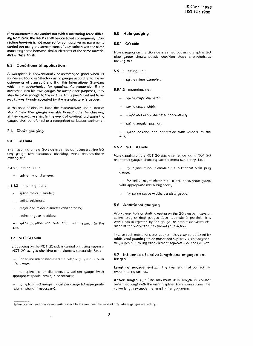
5.7 Influence of active length and engagement length
Length of engagement g, : The axial length of contact be-
tween mating splines.
Active length gW : The maximum axial length In contact
(when working) with the mating spline. For sliding spllnes, the
active length exceeds the length of engagernent
jpline posItIon and orientation with respect tG the am need be verified only where gauges are lacking
3

-.-- ._ -- _-. -11_*1.. x_. _ ..I_
IS 2327 : 1993
IS0 14 : 1982
Y 1
- Active length
I
5.8 Conditions of use of gauges
5.8.1 GO side
GO gauges (spline ring or plug gauge) shall slide @.thout
clearance over the whole length of the gauged workpiece under
their own weight or in accordance with a fixed working load,
gauging being carried out at three angular positions at least,
evenly distributed over the surface. The gauge may be moved
slightly to and fro in order to minimise the effects of friction. -- _
---t--t---- 5.8.2 NOT GO side
Length of engagement NOT GO segmental gauges are used in the same way as gauges
intended for plain workpiece checking. Gauging is carried out
a) Shaft longer than hole at all angular positions.
5.9 Gauge control
5.9.1 GO side
GO gauges are normally controlled by direct measurement.
5.9.2 NOT GO side
NOT GO segmental gauges are controlled under the same con-
ditions as gauges for plain workpiece gauging.
Leng
6 Definitions of gauges
6.1 General
__EIp_L This clause defines the positions and values of tolerances for
GO and NOT GO gauges and their permissible wear limits on
the GO side. It also specifies the length of gauge measuring
parts.
b) Hole longer than shaft The general indications concerning gauges and gauge control
are given in clause 5.
Figure - Active length and engagement length NOTE.3
1 When gauges are manufactured at the maximum material limit,
they shall not present form errors outside permitted tolerances.
As gauges are generally smaller than gauged workpieces, the
actrve length and length of engagement can influence the
maximum permissible errors of alignment of splines (errors of
parallelism of splines with respect to the axis).
If the active length is equal to the length of engagement, spline
altgnment errors will in general and unless otherwise specified
be included in dtmensionat tolerances and checked
simultaneously.
If the active length is longer than the length of engagement, it
mght be necessary to prescribe spline alignment errors
Independent of dimensional tolerances; such tolerances may
then be checked separately, for example, by direct measure-
ment.
2 To limit the number of gauges, only one GO spline plug gauge is
provided to check the minimum limits of hub dimensions (whether
treated or not after broaching).
3 In the following texts, the phrase zero gauge line has been used to
designate the theoretical line from which GO gauges are positioned in
analogy with the zero assembly line (nominal dimension).
The position of the “zero gauge line” has been determined as a func-
tion of workpiece limits at the maximum material condition, in order to
satisfy assembly and operation requirements taking account of the fact
that GO gauges are not segmental gauges but full form gauges.
The “zero gauge line” is in some cases coincident with the zero
assembly line (or nomrnal drmension of assembly).
4 In conformity with clause 4, the minor diameter serves for
workprece fitting. This diameter has therefore been taken as reference
for the control of geometrical defects on other elements (i.e. the other
drameter of width B of splines).
If solne alignment tolerances are to be prescribed, it shall be In thus context the phrases dimensions for fitting and dimensions
consldered that they mus? generally be all the smaller as the ac- not ensuring fitting have been used to destgnate the various
tive length is longer. elements.
4
IS 2327 : 1993
IS0 14 : 1982
6.2 Basic principles
6.2 1 GO gauges
i;O gauges are full forrn gauges cneckirrg spllne minor diameter
(1, major diameter 11 and width /j simultaneously.
6.2.1.1 GO gau>;lrlg of dlmenslons for fitting (minor
!lacnoter c/)
T.i 1 (& gdUglng 01 mlrl;~r dlarTletc?r rl enstlr:ncJ fitting, the VaiUeS
r~r-~ci positIons of dimensional tolerances of hole or shaft
.ja~~c)~, the wear llmtts and fern: tolerances shall conform to
‘r-11:’ reqtilrernents of IS0 P 1938, /SO system of hmits and fits
pdrt 2 lfispectlon of plain workpieces.
,. ^ OL!? &I gauginy of dlmensrorIs not ensuring fitting
t2.2 1 2 1 Posltlon of zero gauge line
* (.I’ (10 yaugtny of major diameter II not ensuring fitting the
:~r gauge iine common to both shaft and hole is located at
:IIO dlstarlce between shaft and hole at the maximum permissi-
r)ir sndterlal condmor of the workpieces concerned.
0’ 3 +.lg.nq of width H, the three cases considered in
‘a~st: 4 shall be taken into account, i.e. sltdtng, close sliding or
-.xwI tyi)e mounting
<3 Sliding type mounting :
: !~e zero gauge line common to both shaft and hole IS
located as in 62.1 2.1 at mid-distance between shaft and
whole at the maximum permissible material condition of the
worko~~ces.
I;! Close sliding type mounting :
’ he hole gauge (plug gauge) is the same as for sliding type
mollnting gaugmg and the hole zero gauge line therefore
11es in the same position.
i-or the shaft gauge (rrng gauge), the zero gauge line is
located on the zero Ime (nominal dimension), without taking
cnto account mid-distance between shaft and hole at the
maximum permissible material condition of the workpieces.
c: Fixed type mounting
The hole gauge (plug gauge) is the same as for sliding or
c:ose sliding type mounting gauging and the hole zero
gauge line therefore lies in the same position.
For the shaft gauge (ring gauge] the shaft zero gauge line is
located with respec? to the shaft maximum permissible
material condition (nominal dimension) above the limit at a
distance equal to tha: retained for sliding type mounting,
I e. half the deviation allowance 1)
6.2.1.2.2 Values and positions of tolerances and wear limits
for GO gauging of dimensions not ensuring fitting.
The values of dimerlslonal tolerances for hole or sh,lfl (;O
gauges correspond to values of yrade 6 ,~r,d ~rlcl~ldt~ l~otl~
dlmensional and form errors (namely c:orlct:rlfrlc.lry, syrr~rr~~lr~
angular position, helix, alignment, etc 1
The deviations between the zero yauye II~CS as deflricsc: II)
6.21 .2.1 and the values of grade 6 qu<trttltlrxs t loscst to :t”t!
lanes correspond to grad<? 4 values
6.2.2 NOT GO gauyes
NO~T GO gauges arc segmc:ntai yauges check III, 1 splir~r. rtil; ,o.
diameter (I, malor diameter I! or widttl /I sepCjr;ltel\
For NOT GO gauging oi each element separ,+tc,iy the V.~IIIP:~
and posltions of yacrye toletar,ces stlall collfc;irr; to try :a’
quirements of ISO’ R 1938, /SO systc’lri of l1rr11f.s ,frlci t/i:,
Part 2 : Inspect/on of p/au1 workpieces.
6.3 Tables of tolerance positions and values
(for hubs, shafts, GO QaLJgeS and NOT GO g<iuges, st:~
tables 4. 5 and 6)
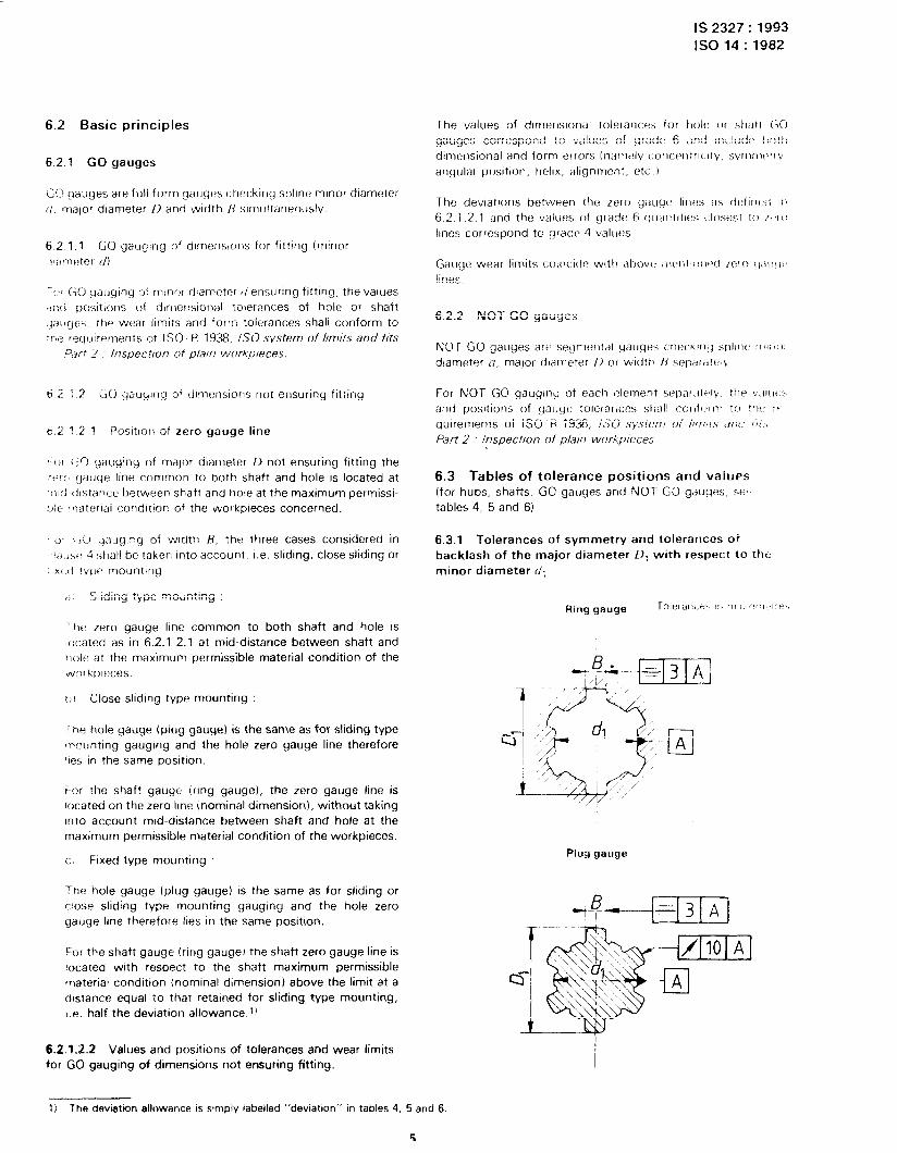
6.3.1 Tolerances of symmetry and tolerances of
backlash of the major diameter 0, with respect to tht:
minor diameter d.,
Plug gauge
11 The deviatton allowance IS smply labelled “deviation” in tables 4, 5 and 6.
5
IS 2327: 1993
IS0 14 : 1982
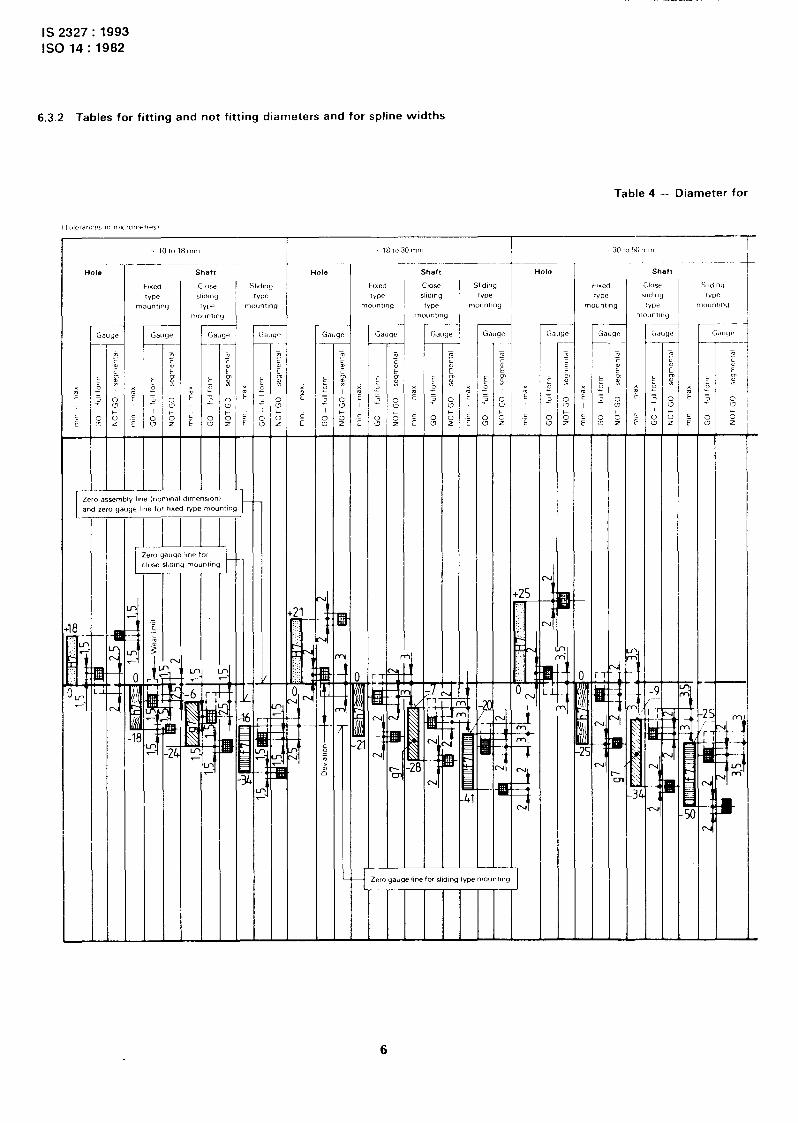
6.3.2 Tables for fitting and not fitting diameters and for spline widths
Table 4 - Diameter for
HOI.3 Shaft
r r. r Gauge
i
m
,
, -1 /
21
..: .:..
i .:
?;
I-- , .I
-
5 ‘r- I
3
6

L___. ^._. -- __ .._---
IS2327:1993 Iso14:1982
fitting Minor diameter
x
?
E
-
40 ,.. . . ‘.
: R . . . .
:
0 i
* 1 0
rl
i n
I--
Y
-
1
I-
E5 n
L A.
7

IS 2327: 1993 IS0 14 : 1982
Table 5 -- Diameter not
(Tolerances in micrometresl
1 lOto18mm 1 40 to 50 IllIn ’ !xlto
Hole
> 18 to 30 mm > 30 to 40 mm
Hole Shaft Hole Shaft Shaft lole
r Gi
E ‘0 =
3
“7 i2 -
N
_
/
N
-
_I
E b
f ‘; 8
cu
-
cu
I -
-
-i In
Zero assembly line (nominal dimensions)
8
-. .____--
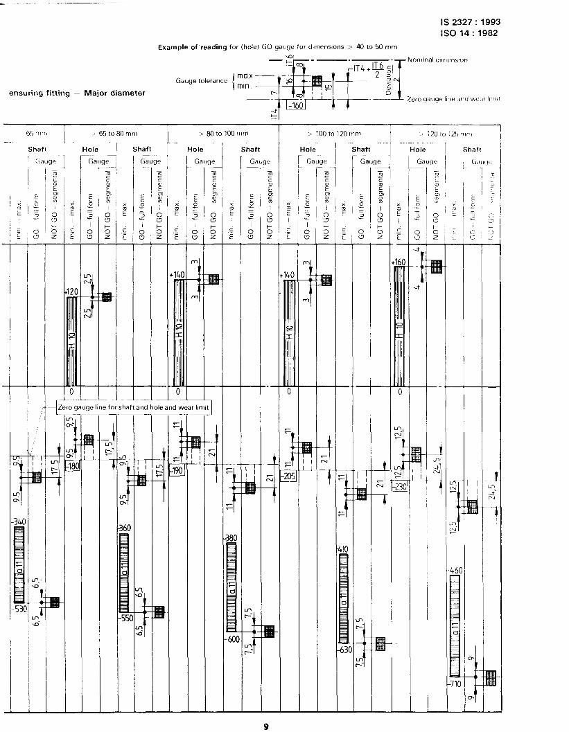
IS2327:1993 ISO14:1982
Example of reading for (hole) GO gauge for dlmenslons > 40 to 50 mm
Gauge tolerance
Nomtnal dlmrnslon
ensuring fitting - Major diameter
> 65 to 80 mm > 6OtolOOmm > 100to120mm ’ 120 to 125 ‘1111,
Hole / Shaft Hole -r Shaft Hole Shaft Hole Shaft
i r r x Gauc le Gi _
Gauge Gauge
2 E I
.E E
-
-.
F
i F
38(
--fZero gauge line for shaft and hole and wear limit 1

IS 2327 : 1993 IS0 14 : 1982
Table 6 - Widths of splines - Sliding,
(Tolerances in micrometres)
< to3mm > 3 to 6 mm
Hole HOI63 Shaft
Close
sliding
me mounting
Shaft
Close
sliding
tvpe mounting
Fixed
tvpe mounting
Sliding
type mounting
Fixed
we mounting
Sliding
me mounting
1 -i Ga
I I-
r r r r r Ga Ill< -
E b = 3
7
s -
3e Gi NJ! -
E z =
2 I
8 I -
Ga UC GZ 3U! -
E P = 3
*;
8 I -
w Gi -
E 0’ ?I
2 I
8 -
ii
Gauge au! -
E b ?I
2 I
8 - I E I
.c_ E -
2 E I
.c E -
E I
.c E
5 I
.c E
E I
.r E
50
iz I
.E E
-
: ._ f .- L 0
I I I I I I I I Zero assembly line (nominal dimensions)
I I I
~~~~~~~t~~r
for close sliding type mounting In
N
i
In
cu-
Kl F-
. .
i K: .-. _-
I limit
1
Zero gauge line and wear limit for sliding type mounting
I) For the close sliding mounting, the wear limit of GO gauges (of shaft) has been located at the nominal dimension, without taking the deviation/2
nto account.
10
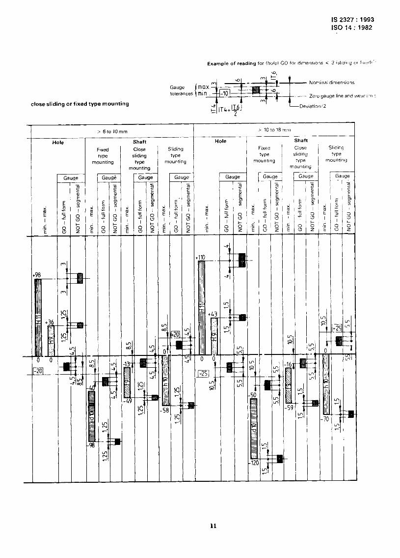
IS 2327 : 1993 IS0 14 : 1982
Example of reading for (hole) GO for dlmenslons < 3 (slrdtng or fjxrdr’
Nominal dlmenslons
- Zero gauge line and wear 111111
close sliding or fixed type mounting
> lOto18mm > 6to 70mm
Hole Shaft
Ciose
slidrng
type mounting
Hole Shaft
Close
sliding
type mounting
Fixed
type mounting
Sliding
We mounting
Sliding
Ma mounting
Fixed
type mounting
_.
.I6
1 r Gauge r r r Gauge Gl 3UC
-
E’ 6 = 3
-7 I 0 W -
au! Gaug6 Gauge Gauge
I u
P-
L
/
t’
T -
E z = 1
I
0 w
T! -
r-l --
/ n
-
2 E I
.r_ E
-
58
t_
r-
11
IS 2327 : 1993
Iso 14 : 1982
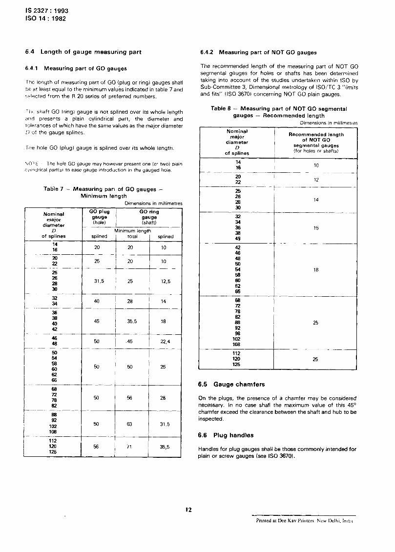
6.4 Length of gauge measuring part 6.4.2 Measuring part of NOT GO gauges
6.4.1 Measuring part of GO gauges
‘The length of measuring part of GO (plug or ring) gauges shall
be at least equal to the minimum valu& indicated in table 7 and
rAected from the R 20 series of preferred numbers.
The recommended length of the measuring part of NOT GO
segmental gauges for holes or shafts has been determined
taking into account of the studies undertaken within IS0 by
Sub-Committee 3, Dimensional metrology of ISO/TC 3 “limits
and fits” (IS0 3670) concerning NOT GO plain gauges
-‘hi- shaft GO (ring) gauge is not splined over its whole length
and presents a plain cylindrical part, the diameter and
tolerances of which have the same values as the major diameter
II of the gauge splines.
Table 8 - Measuring part of NOT GO segmental
gauges - Recommended length
Dimensions in millimt
The hole GO (plug) gauge is splined over its whole length.
Nominal major
diameter D
of splines
Recommended length of NOT GO
segmental gauges (for holes or shafts)
PvVOTE -~~ The hole GO gauge may however present one (c- two) plain
cv’lr~dncal part(s) to ease gauge introduction in the gauged hole.
14 16 10
____-
m 22 12 -__ __t____ _~
25 26 26 14
30
Tatile 7 - Measuring parr of GO gauges -
Minimum length
Dimensions in millimetres
Nominal major
diameter
GO plug GO ring
gauge gauge Ihole) (shaft)
D of splines
14 16
20
22
25 26 26
30
32
34 36 36 40
42
Minimum length splined total splined
20 20 10
I 25 20 10
31.5 ; 25 12,5
-___
40 _”
45 35,5 18
54 58 60
50 (M 25
62 66
66 72 76
50 56 28
62
112 im 56 71 35,5 125
32 34
36 15 36 49
--_ 42 46
z
54 18 58 60 62 66
___ 66 72 76 62
66 25 92 99
102 108
112
120 25 125
6.5 Gauge chamfers
On the plugs, the presence of a chamfer may be considered
necessary. In no case shall the maximum value of this 45’
chamfer exceed the clearance between the shaft and hub to be
inspected.
6.6 Plug handles
Handles for plug gauges shall be those commonly intended for
plain or screw gauges (see IS0 36701.
12
Printed a~ Dee Kav Printers h’ew Delhi. Indid

Standard Mark
The use of the Standard Mark is governed by the provisions of the Bureau of Indian Standards Act, 1986 and the Rules and Regulations made thereunder. The Standard Mark on products covered by an Indian Standard conveys the assurance that they have been produced to complv with the requirements of that standard under a well defined system of inspection, testing and quality control which is devised and supervised by BIS and operated by the producer. Standard marked products are also continuously checked by BIS for conformity to that standard as a further safeguard. Detaiis of conditions under which a licence for the use of the Standard Mark may be granted to manufacturers or producers may be obtained from the Bureau of Indian Standards.

Bureau of Indian Standards
BIS is a statutory institution established under the Bureau of Indian Standards Act, 1986 to promote harmonious development of the activities of standardization, marking and quality certification of goods and attending to connected matters in the country.
Copyright
BIS has the copyright cbf all its publications. No part of these publications may be reproduced in any form without the prior permission in writing of BIS. This does not preclude the free use, in the course of implementing the standard, of necessary details, such as symbols and sizes, type or grade designations. Enquiries relating tu copyright be addressed to the Director ( Publications ), BIS.
Revision of Indian Standards
Amendments are issued to standards as the need arises on the basis of comments. Standards are also rel.iewed periodically; a standard along, with amendments is reaffirmed when such review indicates that no changes are needed; if the review indicates that changes are needed, it is taken Up for revision Users of Indin Standards should ascertain that they are in possession of the latest amendments or edition by referring to the Iatest issue of ‘BIS Handbook’ and ‘Standards Monthly Additions’. Comments on this Indian Standard may be sent to BIS giving the following reference:
Dot : No. LM 10 ( 50.51 )
Amendments Issued Since Publication
Amend No. Date of Issue Text Affected
BUREAU OF INDIAN STANDARDS
Headquarters:
Mansk Bhavan, 9 Bahadur Shah Zafar Marg, New Delhi 11002 Telephones : 331 01 31, 331 13 75 Telegrams : Manaksanstha
Regional
Central :
Eastern :
Offices :
Manak Bhavan, 9 Bahadur Shah Zafar Marg
NEW DELHI 110002
l/l4 C. I. T. Scheme VII M, V. I. P. Road, Maniktola
CALCUTTA 700054
Northern : SC0 445-446, Sector 35-C, CHANDIGARH 160036
Southern : C. 1. T. Campus, IV Cross Road, MADRAS 600113
Common to all Offices )
Telephone
C 33101 31
331 13 75
f37 84 99, 37 85 61
137 56 26, 37 86 62
153 38 43: 53 16 40
153 23 84
C
235 02 16, 235 04 42
235 15 19, 235 23 15
Western : Manakalaya, E9 MIDC, Marol, Andheri ( East ) l-632 92 95, 632 78 58
BOMBAY 400093 < 1632 78,91, 632 78 92
Branch : AHMADABAD. BANGALORE. BHOPAL. BHUBANESHWAR. COIMBATORE. FARTDABAD. GHAZIABAD, GUWAHATI. HYDERABAD. JAIPUR. KANPUR LUCKNOW. PATNA. THIRUVANANTHAPURAM.
Printed at Printwell Printers, Aligarh, India