is 3823 (1988): rolling bearings - static load ratings
TRANSCRIPT

Disclosure to Promote the Right To Information
Whereas the Parliament of India has set out to provide a practical regime of right to information for citizens to secure access to information under the control of public authorities, in order to promote transparency and accountability in the working of every public authority, and whereas the attached publication of the Bureau of Indian Standards is of particular interest to the public, particularly disadvantaged communities and those engaged in the pursuit of education and knowledge, the attached public safety standard is made available to promote the timely dissemination of this information in an accurate manner to the public.
इंटरनेट मानक
“!ान $ एक न' भारत का +नम-ण”Satyanarayan Gangaram Pitroda
“Invent a New India Using Knowledge”
“प0रा1 को छोड न' 5 तरफ”Jawaharlal Nehru
“Step Out From the Old to the New”
“जान1 का अ+धकार, जी1 का अ+धकार”Mazdoor Kisan Shakti Sangathan
“The Right to Information, The Right to Live”
“!ान एक ऐसा खजाना > जो कभी च0राया नहB जा सकता है”Bhartṛhari—Nītiśatakam
“Knowledge is such a treasure which cannot be stolen”
“Invent a New India Using Knowledge”
है”ह”ह
IS 3823 (1988): Rolling bearings - Static load ratings [PGD13: Bearing]


IS 3823 : 1988 IS0 78 : 1987
Indian Standard
ROLLING BEARINGS -STATIC LOAD RATINGS
( Second Revision )
First Reprint APRIL 1994
UDC 621.822.6/.8:620.172
0 BIS 1990
BUREAU OF INDIAN STANDARDS MANAK BHAVAN, 9 BAHADUR SHAH ZAFAR MARG
NEW DELHI 110002
March 1990 Price Group 4

1s 3823 : w8 IS0 76 : 1987
Indian Standard
ROLLING BEARINGS-STATIC LOAD RATINGS
( Second Revision )
NATIONAL FOREWORD
This Indian Standard ( Second Revision ), which is identical with IS0 76 : 1.987 ‘Rolling bearings - Static load ratings’, issued by the International Organization for Standardization ( IS0 1. was adopted bv the Bureau of Indian Standards on 4 November 1988 on the recommendation of the Rolling Bearings Sectional Committee ( EDC 39 ) and approval of the Mechanical Engineering Division Council.
This standard was originally issued in 1966, and was revised in 1984 by adoption of IS0 76 : 1978. Consequent upon the revision of the IS0 standard, this Indian Standard has also been revised to bring it in line with the latest IS0 Standard.
In the adopted standard, certain terminology and conventions are not identical with those used in Indian Standards; attention is specially drawn to the following:
a) Wherever the words ‘International Standard’ appear, referring to this standard, they should be read as ‘Indian Standard’; and
b) Comma (,) has been used as decimal marker in the International Standard, while in Indian Standards, the current practice is to use point (.) as the decimal marker.

As in the Original Standard, this Page is Intentionally Left Blank

IS 3823 : 1888 IS0 78 : 1887
0 introduction
Permanent deformations appear in rolling elements and raceways of rolling bearings under static loads of moderate magnitude and increase gradually with increasing load.
It is often impractical to establish whether the deformations appearing in a bearing in a specific application are permissible by testing the bearing in that application. Other methods are therefore required to establish the suitability of the bearing selected.
Calculations carried out in accordance with thii International Standard do not yield satisfactory results for bearings in which, because of application conditions and/or because of internal design, there is a considerable truncation of the area of contact between the rolling elements and the ring raceways. The same limitation applies where application condiions cause deviations from a normal load distribution in the bearing, for example misalignnent, preload or extra large clearance. Where there is reason to assume that such conditions prevail, the user should consult the bearing manufacturer for recommendations and evaluation of staric equivalent load.
Experience shows that a total permanent deformation of 0,OW 1 of the rolling element diameter, at the centre of the most h6avily loaded rolling element/raceway contact, can be tolerated in most bearing applications without the subsequent bearing operation being impaired. The basic static load rating is, therefore, given a magnitude such that approximately this deformation occurs when the static equivalent load is equal to the load rating.
This International Standard is not applicable to designs where the rolling elements operate directly on a shaft or housing sur- .face,‘unless that surface is equivalent in all respects to the be..#.- ing surface it replaces.
Double-row radial be;,ings and double-direction thrust bear- ‘ings are, when referred to in this International Standard. presumed to be symmetrical.
Tests in different countries indicate that a load of the magnitude in question may be considered to correspond to a calculated contact stress of 2 Definitions
- 4 600 MPal) for self-aligning ball bearings,
- 4 200 MPa for all other ball bearings, and
- 4 Ooo MPa for all roller bearings
at the centre of the most heavily loaded rolling eknent/raceway cor&ct. The formulae and factors for the calculation of the basic static load ratings are based on the;e contact stresses.
The permissible static equivalent load may be smaller than, equal to or greater than the basic static load rating, depending on the requirements for smoothness of operation and friction, as well as on actual contact surface geometry. Bearing users without previous experience of these conditions should consult the bearing manufacturers.
For the purposes of this International Standard, the following definitions apply.
2.1 static load: The load acting (‘7 a bearing when the speed of rotation of its rings in relatic to each other is zero.
2.2 basic static radial load rating, Car: Static radial load which corresponds to a calculated contact stress at the centre of the most heavily loaded rolling element/raceway contact of
- 4 600 MPa for self-aligning ball bearings;
- 4 200 MPa for all other radial ball bearing types;
- 4 000 MPa for all radial roller bearings.
This International Standard specifies methods of calculating
1 Scope and field of application
the basic static load rating and the static equivalent load tar rolling bearings within the size ranges shown in the relevant International Standards, manufactured from good quality hardened steel, in accordance with good manufacturing pr.ac- tice and basically of conventional design as regards the shape of rolling contact surfaces.
load rating refers to the radial component of that load which In the case of a single-row angular contact bearing, the radial
causes a purely radial displacement of the bearing rings in re- lation to each other.
NOTE - For these contact stresses, a total permanent deformation of rolling element and raceway occurs which is approximately O,ooO 1 of the rolling element diameter.
1) 1 MPa =: 1 N/mm*
3

IS 2823 : 1888 180 78 : 1887
2.3 b#ic m axial 1-d rating, C,: Static centric axial load which conerpondr to a calculatsd contact stress at the fXllUe of the most heavily loaded rolling element/raceway con- tactof
- 4 200 MPa for thrust ball bearings;
- 4 000 Wa for all thrust roller bearings.
NO~-Fatkecontactstrssws,atota~psrrnsnsmdeWmationof rolling sbixw?t srtd raceway OCCUR which is approximstsly 0,000 1 of
tlmrdlingebmmtdielmm.
2.4 static oquhmht radial load, Pm: Static radial load whichwouldcmmethesameconmct~atthecentreoftt?3 morthsevilybadedrollii-/racewaycontactasthat whichgcarnundertheachralloadcondftions.
2.6 static aquivaht mid load, Pm: Static centric rxid loadwhichwouldc8uaethesamecontactstmsatthecenm, ofthemo8ttKuldybededroHiIlQ-/racewayconmctjs thMWhiChCKZCURSUlldWthg8CtUdlOdconditionr.
2.6 roWwdiamator(applicabieinthecakulationofload ratings),D,:?hedbmeteratthemid&oftherdk3r.
NOTE-Forataperedrok,thisbequaltothsmssnvalueofths diNlWWSMthOthOOdCdshatpCOfnUSatthElsrgeOlldOfKltht3~
alddtherolkM.
Fan~convexrdkr,~isanrpprolti~tionfarthe dmm83rstttwpointofa3ntactbetwssnthsmHsrsndtheribka rsmnnlyatzerolwd.
2.7 rolb length bppliwble in the calculation of load ratings), t,: The Wore&al maximum length of contact bs twwnarollerandthatramwaywhsrethecontactisshorWst.
NOTE-Thishmmlsayt&Jntobesithertbd@ancebetwsnti thOOdCdShWpCOWSOfttMrdkrlIiilNlSthOrdkrChalllfelSW~th~
mC8vaywidthexdUdingthegrindingUndarCURwhiCheverhthe
srtdu.
2.6 nowhI wnmctangle,a:Thean@betweenaplsm, pwpanMMtothebwingaxisandthenominallineoftki reaubltofthafwcestmnamwdbyrbearfngringtoardling damsnt.
2.8 Phch dkmotwr. Dw
2)2 pitch ~Of~rdkr~:ThediOllWMOftb ~~ngtherolkraxesatthemiddleoftherollersin n~inobeering.
3 Symbols
c, = c, =
Dw=
D,,, =
Dw =
L, -=
F, =
Fa =
Pw =
P, =
x0 =
Y o. =
i? =
,. I,, =
i =
a =
basii static radial load rating, in newtons
basic static axial load rating, in newtons
&ch diameter of a ball or roller set, in millimetres
ball diameter, in miknetres
roller diimeter appliibk in the calculation of load mtings,inmillimetres
roller kngth applicable in the calculation of load ratings, in millimetres
.
bearingradialktEJd=GJdlalcomponent of actual bear- ing load, in newtons
baaring axial load = axial component of actual bearing load, in nawtqs
static eqUiilent radial load, in newtons
static equivalent axial load, in newtons
radiilkHdfsctw
axialloadfactor
number of rolling elements in a single row bearing; number of rolling ebments per row of a multi-row bearingwiththasamenumbarofrolHngebmsntsper row
factor whiihdependsonthegeometvofthebaaring wmpoMmsandontheapplicablestresslevel
numberofrowaofkUingebmentsinabaaring
nominalcontactangleofabe0ring, indagrees
4 Radial ball bewings
4.1 Bark static mdbl Ihad mtlng
ThebasicstaticradisfbadratingforradUlmWbwings~given bythefomwb
C,,, - f,,iZD~ccxw
whom the values off, am giwn in tabb 1.
lheformubapplierrto~ngswithrcross--~ grooveradbnotlargerthan0,52D,inmdialsndangukrcun- ~groovsbdlbeerinei~rinessnd0,53D,inndidand angularcontactgrowebdlbecwiflg0utWdngSand~- aligning ball bowing inner ring%
lheload-canyingabiliiofabearingisnotnecmarilyin- cret3sedbytheuseofasmallefgrooveradius.tikredu~by theuseofagroow3radiikgerthanthoseindk8tedinthe previousparagraph.Inthelattercase,acomwmdMh/rs- dllcedwheoff,shaubeused.
IS 3822 : 1888 ISO 78 : 1887
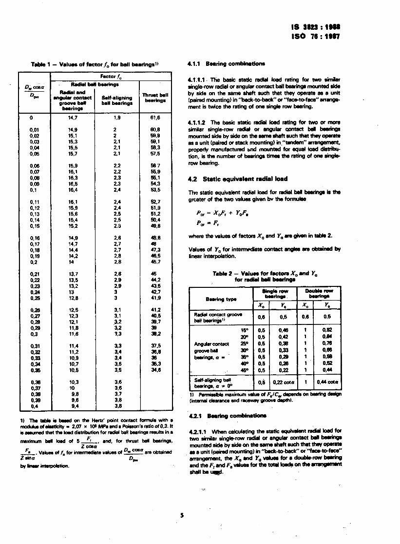
Table 1 - Values of factorf, for bell bearingsl)
Factor ./,
D-c&a ’ Radial bsll bearings
% Radialand
ngulw contect &If-aligning Thru8t ball
groove ball bell bearings bOUingS
beerings
0 14.7 1.9 61.6
0.01 14.9 2 60.8 0.02 15.1 2 59.9 0.03 15.3 2.1 58.1 0.04 15.5 2.1 58.3 0.65 15.7 2.1 57.5
0.06 15.9 2.2 567 0.07 16.1 2.2 56.9 0.08 16.3 2.3 55.1 0.09 16.5 2.3 54.3 0.1 16.4 2.4 53,5
0.11 16.1 2.4 52.7 0.12 15.9 2.4 51,9 0.13 15.6 2.5 51.2 0.14 15.4 2.5 50.4 0,15 15.2 2.3 49,6
0,16 14,9 2.6 48.8 0.17 14.7 2.7 $8 0.18 14.4 2.7 47.3 0.19 14.2 2.8 46.5 0.2 14 2.8 45.7
0.21 13.7 2.8 45 0.22 13.5 2.8 44.2 0.23 13.2 2.9 43.5 0.24 13 3 42.7 0.25 12.6 3 41.9
0.26 12.5 3.1 41.2 0.27 12.3 3.1 40.5
0:3 E
12.1 ,3,2 38.7
11.8 11.6 3.2 3.3 39 39.2
0.31 11.4 3.3 0.32 11.2 3.4 E 0.33 10.9 3.4 36’
0.34 10.7 3.5 0.36 10.5 3.5 E$
0.38 10.3 3.6 0.37 10 3.6 03 9.8 3.7 0.39 9.6 3.8 0.4 9*4 3.8
1) ThetabbhbessdontheHera’pointcontactformdawitha modukaofdrrticity = 2.07 x 10s MPCendsPobwn’srati0of0.3. It h~ma~~dhhiknionforndmlbaW~~lttina
meximum bsll bad of 5 F, Z’
and, for thrust bail bsBfin9s.
F. G-G’
Vatm6 of .f, for intenmdiate values of %E are obtained
opl. byGmuinte@etknl.
4.1.1 Bearing combinethms
4.lJ.l* The basic static radial load rating for two simiilw single-row radii or angular contact ball beerings mounted side by side on the seme sheft such that they operate es a unit (paired mounting) in “back-to-b&C or “face-to-face” ammge- mentistwicetheratingofonesingler0wb8aring.
4.1.1.2 The basic stetic redid bsd mting for two or mom similar single-row radii or 8ngular contact bdl b08hgs mountedsidebysideonthesameshaftsuchthtthw0PrINO as a unit (paired or stack mounting) in.“tadem” amuwmeM, properly manufactured d mounted for equal losd dktribu- tion,isthenumbsrofbearingstimestheratingofonesingle row bearing.
4.2 Static equivalent radial load
Th9 static equivalent radial Id for radd Ml beeriqs is the grwterofthetwovaluesgivenbvthefomlulee
I’,,, = .XoF, + Y,F,
P,,, = F,
bwherethevdue!3offactofsx,snd Y,tlmgivm in tebb2.
Valuesof Y,forintwmdetecontactenglesere0btainedby
Tabk2- V8h#eeforfwtomX,8d Y, for radid beu bouings
I Singkrow I DouWroW
- maxwnum vmue OI ‘,/Cw
lintsmai clearance and raceww groove de@M
42.1 Bowing combiwtiom
4.2.1.1 When cekulating the stetic e&dent rekiel bed for twosimilarsinglwowradid0ranguhrC0tlWCtbd~ mountedsidebysi&onthesameahdtsuchthatthqopaats as a unit (paired mounting) in ‘%eck-M 0r“WCe-to-M srmqement,theX,andY&fduesforrdoubkuuw~ andtheF,andF,vduesforthetoblkmd8ontho~ &bdlbeu@.

IS 3823 : 1988 IS0 78 : 1987
4.2.1.2 When calculating the static equivalent radial load for two or more similar single-row radial or angular contact ball bearings mounted side by side on the same shaft such that they operate as a unit (paired or stack mounting) in “tandem” arrangement, the X0 and Y, values for a single-row bearing and the Fr and FB valiues for the total loads on the arrangement shall be used.
5 Thrust ball bearings
5.1 Basic static axial load rating
The basic static axial load rating for single- or double-direction thrust ball bearings is given by the formula
C0.S = fOZSw sina
where the values off0 are given in table 1 and Z is the number of balls carrying load in one direction.
The formula applies to bearings with a cross-sectional raceway groove radius not larger than 0,!54 0,.
The load-cmying ability of a bearing is not necessarily in- creased by the use of a smaller groove radius, but is reduced by the use of a larger groove radius. In the latter case, a cor- respondingly reduced value off, shall ba used.
5.2 Static equivalent axial load
The static equivalent axial load for thrust ball bearings with Q + 900 is given by the formula
P, = 2,3 F, tana + Fa
This formula is valid for all ratios of radial load to axial load in the case of double-direction bearings. For single-direction bear- ings, it is valid where F,/F, c 0,44 cota and gives satisfactory but less conservative values of P, for F,/Fa up to 0,67 cota.
Thrust ball bearings with a = 900 can support axial loads only. The staticequiv,lent axial load for this type of bearing’is given by tha formula
6.1.1 Bearing combinations
6.1.1.1 The basic static radial load rating for two similar single-row roller bearings mounted side by side on the same shaft such that they operate as a unit (paired mounting) in “back-to-back” or “face-to-face” arrangement is twice the rating of one single-row bearing.
6.1.1.2 The basic static radial load rating for two or more similar single-row roller bearings mounted side by side on the same shaft such that they operate as a unit (paired or stack mounting) in “tandem” arrangement, properly manufactured and mounted for equal load distribution, is the number of bear- ings times the rating of one single-row bearing.
6.2 Static 8qUiV818nt radial load
The static equivalent radial load for roller bearings with a + O” is the greater of the two values given by the formulae
P,,, = X,F, + Y,F,
P or = F,
where the values of factors X,, and Y, are given in table 3.
Table 3 - Values for factors X0 and Y,, for radial roller bearings with a # O”
The static equivalent radial load for radial roller bearings with a = 0°, and subjected to radial load only, is given by the formula
PO, = Fr
NOTE - The ability of radial roller bearings with a = O” to support axial loads varies considerably with bearing design and execution. The bearing ussr should therefore consult the bearing manufacturer for recommendations regarding the evaluation of equivalent load in cases where bearings with a = O” are subjected to axial load.
6.2.1 Bearing combinations
P, = F,
5 Radial roller bearings
6.1 Basic static tadi load rating
The basic static radial load rating for radial roller bearings is . given by the formula
D, cosa
D > iZL,D, cosa
VW
6.2.1.1 When calculating the static equivalent radial load for two similar single-row angular contact roller bearings mounted side by side on the same shaft such that they operate as a unit (paired mountingi in “back-to-back” or “face-to-face” arrange- ment, the X, and Y0 values for a double-row bearing and the F, and FB for the total loads on the arrangement shall be used.
6.2.1.2 When calculating the static equivalent radial load for two or more similar single-row angular contact roller bearings mounted side by side on the same shaft such that they operate as a unit (paired or stack mounting) in “tandem” arrangement, the X0 and Y, values for a single-row bearing and the F; and Fa values for the total loads on the arrangement shall be used.

IS 3823 : 1988 IS0 76 : 1987
7 Thrust roller bearings
7.1 Basic static axial load rating
The basic static axial load rating for single- and double- direction thrust roller bearings is given by the formula
where Z is the number of rollers carrying load in one direction.
In cases where rollers have different lengths, ZL, is taken as the sum of the lengths, defined in 2.7, of all the rollers carrying load in one direction.
7.1 .l Bearing combinations
The basic static axial load rating for two or more similar single- direction thrust roller bearings mounted side by side on the same shaft such that they operate as a unit (paired or stack mounting) in “tandem” arrangement, properly manufactured and mounted for equal load distribution, is the number of bear- ings timas the rating of one single-direction bearing.
7
7.2 Static equivalent axial load
The static equivalent axial load for thrust roller bearings with a # %I0 is given by the formula
Pea = 2,3 Fr tana + F,
This formula is valid for all ratios of radial load to axial load in the case of double-direction bearings. For single-direction bear- ings, it is valid where F&F, < 3.44 cota and gives satisfactory but less conservative values of P, for F,IF, up to 0.67 cota.
Thrust roller bearings with a = !W can support axial loads only. The static equivalent axial load for this type of bearing is given by the formula
7.2.1 Bearing combinations
When calculating the static equivalent axial load for two or more similar thrust roller bearings mounted side by side on the same shaft such that they operate as a unit (paired or stack mounting) in “tandem” arrangement, the F, and Fa values for the total loads acting on the arrangement shall be used.
Rrprogmphy Unit, BIS, New Delhi, Irrdi;r

Bureau of Indian Standards
BIS is a statutory institution established under the Bureau of In..fian Standards Act, 1986 to promote harmonious development of the activities of standardization, marking and quality certification of goods and attending to connected matters in the country.
Copyright
BIS has the copyright of all its publications. No part of these publications may be reproduced in any form without the prior permission in writing of BIS. This does not preclude the free use, in the course of implementing the standard, of necessary details, such as symbols and sizes, type or grade designations. Enquiries relating to copyright be addressed to the Director ( Publications ), BIS.
Revision of Indian Standards
Indian Standards are reviewed periodically and revised, when necessary and amendments, if any, nre issued from time to time. Users of Indian Standards should ascertain that they are in possession of the latest amendments or edition. giving the following reference:
t
Amendmeats Issued Since Publication
Amend No. Date of Issue Text Affected
BUREAU OF INDIAN STANDARDS
Headquarters :
Manak Bhavan, 9 Bahadur Shah Zafar Marg, New Delhi 110002 Telephones : 33101 31, 331 13 75 Telegrams : Manaksanstha
( Common to all Offices )
Regional Offices :
Central : Manak Bhavan, 9 Bahadur Shah Zafar Marg, NEW DELHI 110002
Eastern : l/14 C. I. T. Scheme VII M, V. I. P. Road, Maniktola CALCUTTA 700054
Telephone
I 331 01 31 331 13 75
37 86 62
Northern : SC0 445-444 Sector 35-C, CHANDIGARH 160036 2 1843
Southern : C. I. T. Campus, IV Cross Road, MADRAS 600113 41 29 16
Western : Manakalaya, E9 MIDC, Marol, Andheri ( East ) BOMBAY 400093
6 32 92 9s
Branches : AHMADABAD. BANGALORE. BHGPAL. BHUBANESHWAR COIMBATORE. FARIDABAD. GHAZIABAD GUWAHATI, HYDERABAD. JAIPUR. KANPUR. PATNA. TRIVANDRUM.
Reprngrapbp Unit, BIS, New Delhi ) India