is 4720 (1982): code of practice for ventilation of ...is :4720- 1982 1.1.1 for installation,...
TRANSCRIPT

Disclosure to Promote the Right To Information
Whereas the Parliament of India has set out to provide a practical regime of right to information for citizens to secure access to information under the control of public authorities, in order to promote transparency and accountability in the working of every public authority, and whereas the attached publication of the Bureau of Indian Standards is of particular interest to the public, particularly disadvantaged communities and those engaged in the pursuit of education and knowledge, the attached public safety standard is made available to promote the timely dissemination of this information in an accurate manner to the public.
इंटरनेट मानक
“!ान $ एक न' भारत का +नम-ण”Satyanarayan Gangaram Pitroda
“Invent a New India Using Knowledge”
“प0रा1 को छोड न' 5 तरफ”Jawaharlal Nehru
“Step Out From the Old to the New”
“जान1 का अ+धकार, जी1 का अ+धकार”Mazdoor Kisan Shakti Sangathan
“The Right to Information, The Right to Live”
“!ान एक ऐसा खजाना > जो कभी च0राया नहB जा सकता है”Bhartṛhari—Nītiśatakam
“Knowledge is such a treasure which cannot be stolen”
“Invent a New India Using Knowledge”
है”ह”ह
IS 4720 (1982): Code of Practice for Ventilation of SurfaceHydel Power Stations [WRD 15: Hydroelectric Power HouseStructures]

IS :4720 - 1982
Indian StandardCODE OF
PRACTICE FOR VENTILATION OFSURFACE HYDEL POWER STATIONS
( First Revision 1
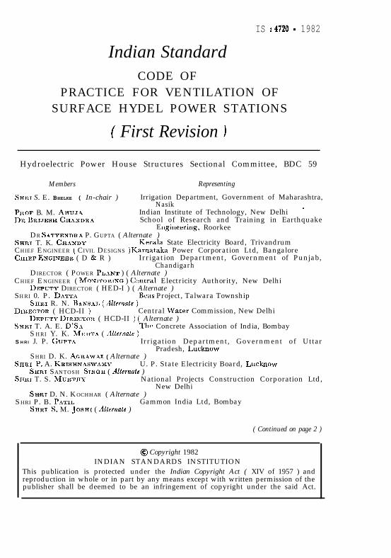
Hydroelectric Power House Structures Sectional Committee, BDC 59
Members Representing
Srrr:~ S. E. BHELKE ( In-chair ) Irrigation Department, Government of Maharashtra,Nasik
PI~OF B. M. AHUJ~ Indian Institute of Technology, New Delhi ’Dn B~I.JESH CHANDRA School of Research and Training in Earthquake
Engineering, RoorkeeDR SATYENDR~ P. GUPTA ( Alternate )
SHRI T. K. CH~NDY Kerala State Electricity Board, TrivandrumCHIEF ENGINEER ( CIVIL DESIGNS )Karnataka Power Corporation Ltd, BangaloreCEIEF ENGINEER ( D & R ) Irrigation Department, Government of Punjab,
ChandigarhDIRECTOR ( POWER PL.~NT ) ( Alternate )
CHIEF ENGINEER ( M~NITORIX~ ) Czntral Electricity Authority, New DelhiDEP~JTY DIRECTOR ( HED-I ) ( Alternate )
S HRI 0. P. DATTASHRI R. N. B.~NSAI, ( .4Zternate )
Beas Project, Talwara Township
DIRECTOR ( HCD-II ) Central MJater Commission, New DelhiDEPUTY DIRB~TOR ( HCD-II ) ( Alternate )
SHXJ T. A. E. D’SaS HRI Y. K. Mn.1-r~~ ( Alternate )
The Concrete Association of India, Bombay
S HRI J. P. Gaprn Irrigation Department, Government of Uttar
SHRI D. K. AGRAWAL ( Alternate )Pradesh, Lucknow
SISRI P. A. KRISHN.4SWAMY U. P. State Electricity Board, LucknowSHXI SANTOSH SINGII ( rllternate )
SHE1 T. S. MURTHY National Projects Construction Corporation Ltd,New Delhi
SERI D. N. KOCHHAR ( Alternate )SHRI P. B. P~TIL
SHRI S. M. JOSHI ( Alternate )Gammon India Ltd, Bombay
( Continued on page 2 )
@ Copyright 1982INDIAN STANDARDS INSTITUTION
This publication is protected under the Indian Copyright Act ( XIV of 1957 ) andreproduction in whole or in part by any means except with written permission of thepublisher shall be deemed to be an infringement of copyright under the said Act.
IS :4720- 1982
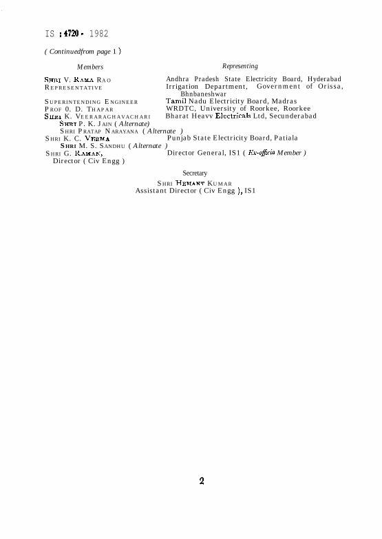
( Continuedfrom page 1 )
Members
SHRI V. RAMA RA OREPRESENTATIVE
SUPERINTENDING ENGINEERPROF 0. D. THAPARSHRI K. VEERARAGHAVACHARI
Representing
Andhra Pradesh State Electricity Board, HyderabadIrrigation Department, Government of Orissa,
BhnbaneshwarTamil Nadu Electricity Board, MadrasWRDTC, University of Roorkee, RoorkeeBharat Heavv Electricals Ltd, Secunderabad
SHRI P. K. JAIN ( Alternate)SHRI PRATAP NARAYANA ( Alternate )
SHRI K. C. VE~MA Punjab State Electricity Board, PatialaSHRI M. S. SANDHU ( Alternate )
SHRI G. RAMAN, Director General, IS1 ( Ex-oflcio Member )Director ( Civ Engg )
Secretary
SHRI HEMANT KUMARAssistant Director ( Civ Engg ), IS1
2
IS : 4720 - 1982
Indian StandardCODE OF
PRACTICE FOR VENTILATION OFSURFACE HYDEL POWER STATIONS
s( First Revision )
0 . FOREWBRD
0.1 This Indian Standard was adopted by the Indian StandardsInstitution on 14 January 1982, after the draft finalized by theHydroelectric Power House Structures Sectional Committee had beenapproved by the Civil Engineering Division Council.
0.2 This standard was first published in 1968. Since then moreexperience has been gained in the field and to reflect the latest practicesthe present revision has been taken up. In this revision, requirements ofnatural ventilation with the provision of windows and ventilators havebeen included.
0.3 Due consideration should be given to the ventilation requirements indesigning surface hydel power stations. Provision for ventilation becomesnecessary in the power station building to provide for any or all of the~following purposes:
a) To prevent temperature stratification,b) To remove contaminated or vitiated air,c) To remove waste heat from generators,d) To provide for cooling or heating of building,e) To furnish clean/tempered air, andf) To furnish outside air necessary for human comfort.
0.3.1 Ventilation in surface hydel power stations ~by natural meansalone using gravity may be sufficient in some stations to meet the abovementioned purposes. Where these purposes cannot be met by naturalventilation, forced ventilation or combination of the two with heatingand cooling systems, where necessary, may be resorted to ensure clean,and if necessary, tempered air to reach various premises in the powerstation, which will, otherwise, receive little or no ventilation and where,
3
c
IS:4720- 1982
for the protection of equipment and to maintain satisfactory thermalenvironments, the heat to be removed is too great to be handled bygravity.
0.4 In the formulation of this standard, due weightage has been given tointernational co-ordination among the standards and practices prevailingin different countries in addition to relating it to the practices in the fieldin India. This requirement has been met by deriving assistance fromthe following publications:
ASHRAE guide and data book 1977. American Society of Heatin;,Refrigerating and Air-Conditioning Engineers, Inc., New York.
United States of America. Department of the Interior and Bureauof Reclamation. Design Supplement No. 6 Turbine and pumps.Government Printing Office, Washington.
United States of America. Department of the Interior and Bureauof Reclamation. D e s i g n S u p p l e m e n t N o . 8 Miscdlaneousmechanical equipment and facilities. Government PrintingOffice, Washington.
0.5 This standard is one of a series of Indian Standards on surface hydelpower stations. Other standards so far published in this series are:
IS : 4247 ( Part I )-1978 Code of practice for structural design ofsurface hydel power stations: Part I Datafor design (first revision ).
IS : 4461-1979 Code of practice for joints in surface hydroelectricpower stations (jr& revision ).
IS : 4721-1968 Code of practice for drainage and dewatering ofsurface hydel power stations.
0.6 For the purpose of deciding whether a particular requirement ofthis standard is complied with, the final value observed or calculated,expressing the result of a test or analysis, shall be rounded off ina c c o r d a n c e w i t h I S : 2-1960”. The number of significant placesretained in the rounded off value should be the same as that of thespecified value in this standard.
1. SCOPE
1.1 This standard covers basic requirements regardingventilation system for surface hydel power stations.
des ign of
*Rules for rounding off numerical values ( revised ).
4
IS :4720- 1982
1.1.1 For installation, operation, testing and maintenance of ventilatingsystem reference may be made to IS : 3103-1975*.
1.2 This standard, however, does not cover the requirements forventilation of generators or other equipment and specifications for fans,ducts and other equipment used in the ventilation of surface hydel powerstations.
2. TYPES OF VENTILATION
2.1 The ventilation may be of following types:
a) Natural, that is, by forces set in motion by the heat of sun,namely, winds; and
b) Forced or artificial, that is, by extraction or propulsion.
3. GENERAL RULES FOR DESIGN
3.1 Natural Ventilation
3.1.1 Thorough ventilation of power house building should be aimedat by the provision of adequate windows and ventilators.
3.1.2 Provision of Windows and Ventilators - The object of providingwindows and ventilators is two-fold, that is, to get fresh air and light.The minimum area of windows and ventilators to be provided in powerhouse building shall be one-tenth of the floor area. However, effortsshould be made to increase it to one-fifth of the floor area. Windowsshould be well distributed and be located on windward side at low leveland should not, as far as possible, be obstructed by adjoining structuresor partitions. When wind direction is variable, windows should beprovided on all sides, if possible. Effort should be made to developcross-ventilation. For protection against fire, it is preferable to providesteel doors and windows in power house and auxiliary rooms. Referencemay be made to IS : 1038-19757 and IS : 1361-1978:. The ventilatorsshould be fixed as high as possible for proper expulsion of warm air.Full advantage should be taken of sunshine which is important inventilation its availability depends on the orientation of the power housewhich in turn may depend on site condition. In providing openings,measures to guard against entry of birds, moths, etc, should be taken.
3.2 Forced Ventilation
3.2.1 Forced ventilation system is designed keeping the inlet fancapacity 10 percent more than the exhaust fan capacity.
*Code of practice for industrial ventilation ( jimt r&ion ).tStee1 doors, windows and ventilators ( second r&ion ).@tee1 windows for industrial buildings (jirst reoision ).
5
IS :4720 - 1982
3.2.2 Unassigned rooms and storage rooms should be carefullyconsidered, so that sufficient ventilation may be provided in those whichmight be used for purpose requiring additional ventilation in the future.
3.2.3 In portions of the power station building where moisturecondensation is anticipated, dehumidified air should be supplied toprevent condensation, as condensation causes deterioration of point,corrosion of metal surfaces and breakdown of insulation on electricalequipment.
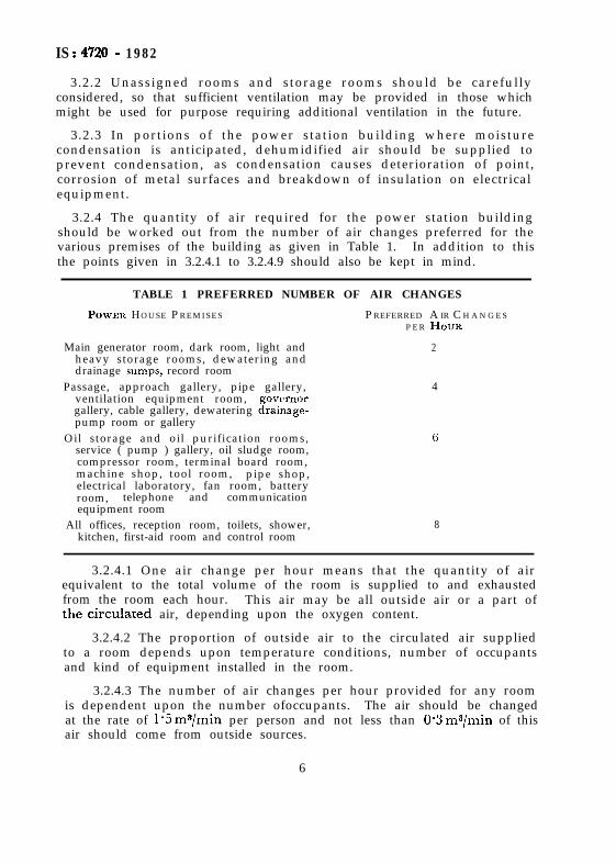
3.2.4 The quantity of air required for the power station buildingshould be worked out from the number of air changes preferred for thevarious premises of the building as given in Table 1. In addition to thisthe points given in 3.2.4.1 to 3.2.4.9 should also be kept in mind.
TABLE 1 PREFERRED NUMBER OF AIR CHANGES
POWER HOUSE P R E M I S E S P REFERRED A IR C H A N G E SP E R Hou~t
Main generator room, dark room, light andheavy storage rooms, dewatering anddrainage sumps, record room
2
Passage, approach gallery, pipe gallery,ventilation equipment room, govrrnorgallery, cable gallery, dewatering drainage-pump room or gallery
4
Oil storage and oil purification rooms,service ( pump ) gallery, oil sludge room,compressor room, terminal board room,machine shop, tool room, pipe shop,electrical laboratory, fan room, batteryroom, telephone and communicationequipment room
6
All offices, reception room, toilets, shower,kitchen, first-aid room and control room
8
3.2.4.1 One air change per hour means that the quantity of airequivalent to the total volume of the room is supplied to and exhaustedfrom the room each hour. This air may be all outside air or a part ofthe~circulated air, depending upon the oxygen content.
3.2.4.2 The proportion of outside air to the circulated air suppliedto a room depends upon temperature conditions, number of occupantsand kind of equipment installed in the room.
3.2.4.3 The number of air changes per hour provided for any roomis dependent upon the number ofoccupants. The air should be changedat the rate of 1.5 ms/min per person and not less than O-3 ms/min of thisair should come from outside sources.
6
IS:4720-1982
3.2.4.4 The number of air changes per hour provided for roomscontaining equipment generating heat shall necessarily be increased,depending on the amount of heat to be carried out by the ventilatingsystem.
3.2.4.5 For medium climates, the maximum temperature rise of aircarrying off heat of transformers should be limited to 2O”C, and for hotclimates the temperature rise shall be limited to 16°C ; however, the finaltemperature of the air exhausted shall not exceed 45°C.
3.2.4.6 Air supplied to rooms containing special mechanical orelectrical equipment should be filtered aridcirculation maintained at aminimum, through diffusers, to prevent the accumulation of dust onsensitive mechanisms. The relative humidity of air supplied should notbe higher than 65 percent.
3 . 2 . 4 . 7 R o o m s w h i c h m a y c o n t a i n a i r c o n t a m i n a t e d w i t hobjectionable or harmful odours, carbon dioxide gas or smoke, shouldbe exhausted directly to the outside of the building.
3.2.4.8 When heating or cooling units are provided in the powerhouse, their effect on the quantity and temperature or air circulatingthrough the building shall be considered.
-3.2.4.9 The spacing of supply and exhaust openings in long roomsor galleries should be such that sufficient air changes per hour areprovided along the full length of the room.
4. FANS
4.1 Forced air ventilation is provided by propeller, axial or centrifugaltype fans powered by electric motors. Propeller fans may be used eitherto supply or exhaust where no duct system, filters or other restrictionsare in the air passage. When duct system is used, axial or centrifugalfans may be used for any type of operation involving the movement ofair and may be accompanied by filters, and coolers or heaters wherecleaning and tempering of supply air is required. Choice of a particulartype of fan may be made by consulting the fan manufacturers data,which give full operating characteristics with a preferred range ofoperation for a particular fan.
5. AIR INTAKE AND EXHAUST -OPENINGS
5.1 Openings are provided for intake and exhaust of air where outsideair is required for ventilation. Where natural ventilation is used, theopening of windows is sometimes sufficient. For forced ventilation,special openings are required. The number of openings for intake andexhaust of air depends on the space arrangement in the building, on thesize of the building and the design of the ventilation system. Small
7
IS:4720- 1982
power plants may have one opening of each type. For larger powerplants, separate outside air intake should be installed for the control,service and main unit bays. Each intake should be provided with stormlouver+ screens, and dampers for controlling the mixcure of outside andcirculated air. The obstruct ive ef fect of the louvers should becompensated for by making the gross area of the initial intake twice thearea of the connecting duct. When filters are used, the area shall beincreased to accommodate the required filter area.
5.2 Air opening may be placed any where on the exposed walls or roofof the power plant building, except that, in order to reduce dust intake,air intake should be at least 1.25 m above ground or deck level.
5.3 Air is exhausted from the building through exhaust openings providedwith louvers or by axial-.flow exhaust fans located near the roof in themain generator room. Normally, the number of exhaust openings maybe more than the air inlet openings, since the spaces to be exhausted areseldom located in the same general area, nor do they have commonrequirements. Individual centrifugal fans and connecting ducts areusually installed to exhaust air from toilets, battery rooms and oil storagerooms.
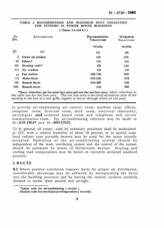
5.4 The size of air openings is dependent on noise level, and to a lesserdegree, on horse power requirements, since the smaller the opening thehigher will be the noise level and the resistance. The size of airopenings may also be worked out from the air velocity as recommendedin Table 2, which will be found to give satisfactory results in designingconventional systems.
6. AIR CLEANING
6.1 It is desirable to clean the air entering the power plant building inorder to remove the air-borne dust particles which, if allowed to enterthe building, may have an abrasive effect on rotating machinery,interfere with the operation of electric or electronic devices, and may,otherwise settle on equipment, giving a dirty appearance. The a i rfilters are usually located upstream of the fan. The size of the air filtersmay be determined by the recommended velocity of air passing as givenin Table 2. The choice of the air filter may be made by reference tothe manufacturer’s catalogues.
7 . AIR-CONDITIONING
7.1 When the desired temperatures and humidities inside the hydel powerstation are not obtainable by ordinary ventilation, air-conditioning maybe resorted to by heating or cooling the entering air to the desiredtemperature to maintain comfortable working conditions in the premisesoccupied by working personnel. The premises where it will be desirable
8
IS : 4720 - 19S2
TABLE 2 RECOMMENDED AND MAXIMUM DUCT VELOCITIESFOR SYSTEMS IN POWER HOUSE BUILDINGS
( Clauses 5.4 and 6.1 )
I%D ESIGNATION RE~~WSIENDED MAXLMUM
VELOCIZES VELOCITIES
(1) (2)9 Outer air intakes
ii) Filters*iii) Heating coils*iv) Air washers
v) Fan outletsvi) Main ducts
vii) Branch ductsviii) Branch risers
m/min m/min
(3) (4)
150 370110 110180 210150 150
500-730 850370-550 670250-300 550
250 500
*These velocities are for total face area and not the net free area; other velocities inthe table are for net free area. The net free area is the total minimum area of theopening in the face of a coil, grille, register or louver through which air can pass.
to provide air-conditioning are control. room, machine shop, offices,reception room, first-aid room, dark room, electrical laboratory,switchgear land terminal board room and telephone and carriercommunication room. For air-conditioning reference may be made toIS : 659-1964* and IS : 660-1963t.
7.2 In general, all rooms, used by sedentary personnel shall be maintainedat 22°C with a relative humidity of about 50 percent, or in special caseslocal radiant type portable heaters may be used for the space actuallyoccupied. Operat ion of the a ir -condit ioning system should beindependent of the main ventilating system and the control of the systemshould be automatic by means of thermostatic devices. Heating andcooling load computations may be based on currently accepted standardpractice.
8. DUCTS
8.1 Where positive ventilation requires ducts for proper air distribution,considerable advantage may be achieved by incorporating the ductsinto the building structure and by having the interior surfaces carefullyfinished to render them smooth and air-tight.
*Safety code for air-conditioning ( revised ).TSafety code for mechanical refrigeration ( revised).
9
IS :4720 - 1982
8.2 Where meta duct work is installed, it shah be fabricated fromgalvanized steel or aluminium sheets, and shall conform to IS : 655-1963”.
8.3 The transfer of air by ducts; from source to delivery point, shouldbe as direct as practicable with the fewest possible bends. Flexibleconnections shall be provided between fans and duct work to prevent thenoise of fan vibration being transmitted directly to the sheet-metal ducts.
8.4 The size of the air ducts shall be worked out from the permissibleair velocities given in Table 2.
8.5 Supply and exhaust ducts of acid battery rooms shall be painted withacid resistant pain1 both inside and outside.
8.6 Ducts shall be suitably insulated wherever required.
9. AIR DISTRIBUTION CONTROL
9.1 To regulate the flow of air in a ventilating system, control dampersshall be provided throughout. At outside air intakes, multi-louverdampers shall be used to control the amount of air admitted. A similardamper is required on inside air intakes to control the amount ofrecirculated air. These two dampers shall be interconnected to permitregulation of the proportion of outside air to inside air used in theventilating system. These may be operated manually or automatically.Back-draft dampers are used where it is desired to prevent a reverse flowof the air, such as the air supply duct to a battery room. Exhaust ductsfrom rooms containing a fire hazard shall have dampers which can beautomatically and manually closed in case of fire. Discharge openings,provided with propeller exhaust fans, should be fitted with motor ormechanically operated type multi-louver dampers, which will open andclose automatically when the fan motor starts and stops.
*Specification for metal air ducts ( revised ),
10