is 5878-6 (1975): code of practice for construction of ...is : 5878 ( part vi ) - 1975 1.2 this code...
TRANSCRIPT
Disclosure to Promote the Right To Information
Whereas the Parliament of India has set out to provide a practical regime of right to information for citizens to secure access to information under the control of public authorities, in order to promote transparency and accountability in the working of every public authority, and whereas the attached publication of the Bureau of Indian Standards is of particular interest to the public, particularly disadvantaged communities and those engaged in the pursuit of education and knowledge, the attached public safety standard is made available to promote the timely dissemination of this information in an accurate manner to the public.
इंटरनेट मानक
“!ान $ एक न' भारत का +नम-ण”Satyanarayan Gangaram Pitroda
“Invent a New India Using Knowledge”
“प0रा1 को छोड न' 5 तरफ”Jawaharlal Nehru
“Step Out From the Old to the New”
“जान1 का अ+धकार, जी1 का अ+धकार”Mazdoor Kisan Shakti Sangathan
“The Right to Information, The Right to Live”
“!ान एक ऐसा खजाना > जो कभी च0राया नहB जा सकता है”Bhartṛhari—Nītiśatakam
“Knowledge is such a treasure which cannot be stolen”
“Invent a New India Using Knowledge”
है”ह”ह
IS 5878-6 (1975): Code of practice for construction oftunnel conveying water, Part 6: Steel lining [WRD 14: WaterConductor Systems]

is : 5878 ( Pet VI ) - 19%
Indian Standard
CODE OF PRACTICE FOR CONSTRUCTION OF TUNNELS
PART VI STEEL LINING
(Third Reprint NOVEMBER 1991)
UDC 624.191.2:624.191.835
@ Copyright 1975
BUREAU OF INDIAN STANDARDS MANAK BHAVAN, 9 BAHADUR SHAH ZAFAR MARC3
NEW DELHI 110002
Gr 3 June 1975
Indian Standard CODE OF PRACTICE FOR
CONSTRUmION OF TUNNELS
PART VI STEEL LINING
Wakr Conductor Systems Scctioti Committee, BDC 58
-faaha#I SSBI P. M. h3Ame
R
Mt?mb#rs R8#r0S8lUiRg ADDITIONAL D~BE~TOB ( FE )
DEPUTY DIBECWB STANDABDE Mmiatry of Railways, New Delhi
SaeI $ ; $/S&I (Ait- ) . . . Public Works 8c Electricity Department, Govern-
mint of Kamataka, Bangalore Sam K. A. NAUAYANA RAO ( Alfcrnatr )
Csnw ~O~~B~UI~ONENOU~EEB SUPEBIwrmiDma Enol~~gB
Tamil Nadu Electricity Board, Madras
( TECIIXIOAL/CIVIL ) ( Alkrnorr ) CarnBxor mtB( QVIL) Andhra Pradesh
Hyderabad State Electricity Board,
SU~XU~ENDII~IO EN~II~~ ( D-ON h PLUM-• ) ( Allmrdr )
CruBrElto-(c&XL) Kerala State Electricity Board, Trivandrum SEBIK. RUCABHADBA~NAIR(AIILII~(I~C)
~~E*~m~ (Irrigation) Public Works Department, Govcrnmont of’Tami1
SrmBIxTEMD~O EsoUJEsB Nadu, Madras
( D&WC ) ( Altmo(r ) SEEI 0. P. DATTA
Sa81J.S. SIZWiOTA(~flm4t#) Beu Duigns Organization, Nand Township
D-OB ( HGD ; Gent4 Water & Power Gommimkm, New Delhi DB?UTY Ihr=+QB ( PIi-1 ) ( A&#lb#!# ).
bmmos, LmPRI
-1 k. L. &ABYA ( AkIM& )
I~a$~~~;;g~h~ent, Government of
~EBI D. N. DUl'TA Aaum State Electricity Board, &long ( GMwed on pap 2 )
Q cqprighf 1975
BUREAU OF INOIAN -STANDARDS
Tbim publkatiorr ir protected unda the India G&r&ht Ad (XIV of i957) and i reproduction in whole or in part by any mesas except witb written permitsion of the
i publ&ha &all be deaned to be an infringknt of copyright under the aaid Act. I
-
IS : 5878 ( Part \tI ) - 1975
( Continued from page 1 )
Members
SHRI R. G. GANDHI
Representing
SR~I R. K. J~SHI ( Ahnate ) Hindustan Construction Go Ltd, Bombay
SlrarK.C. GEOSAL Alokudyog Services Ltd, New Delhi SHRI A K. BISWAS ( Alternate )
SHRI M. S. JAIN SHRI L. N. KABIRAJ
Geological Survey of India, Calcutta Damodar Valley Corporatron, Dhanbad
S&RI B. S. KAPRE Irrigation & Power Department, Government of
SHRI S M. BHAL~RAO ( Alternate ) Maharashtra, Bombay
SHRI D. N. KOCHHAR National Projects Construction Corporation Ltcl, New Delhi
SHICI K. N. TANEJA ( Alternate ) SIIRI Y. G. PATEL Pate1 Engineering Co Ltd, Bombay
SIIRI c. K CHOKS~I ( Alternate ) SIIRI A. R. RAICHUR SWZRETARY
R. J. Shah 8s Co Ltd., Bombay Ceqtral Boxd of Irrrgation & Power, New Delhi
DEPUTY SECRETARY ( I. 0. ) ( Alfernate ) SURI G. N. TANDON Irrigation Department, Government of Uttar
Pradesh, Lucknow SHRI D. AJITHA SIMIIA, Director General, ISI ( Ex-oficio Member )
Director ( Civ Engg )
Secretary
SRRI K. K. SHARMA Assistant Director ( Civ Engg ) , ISI
Panel for Construction of Tunnels, BDC 58 : P2
Convener
SXRI B. ‘S. KAPRE
Members
Irrigation & Power Department, Government of Mabarashtra, Bombay
ADDITIONAL DIRECTOR ( FE ) Ministry of Railways, New Delhi DEPUTY DIRECTOR STANDARDS
( B & S)-I (Alterde) SHRI C. K. CHOK~III Pate1 Engineering Co Ltd, Bombay DEPUTY DI~EOTOR ( HCD ) SHRI K. C. GHOSAL
Central Water 8s Power Commission., New Delhi Alokudyog Services Ltd, New ‘Delhi
SKRI A. K. BISWAS ( Ahrnate ! SHRI R. K. JOSHI Hindustan Construction Co Ltd, Bombay
SI~SI D. G. KADKADB ( Alternate) SHRI A. R. RAICHUR R. J. Shah & Co Ltd, Bombay SHRI G. L. RAMASWAMiAH Indian Hume Pipe Co Ltd, Dehradun
SHRI S. A. VIJAYAKEEETI ( Alternate ) SHRI K. SHAMA RAO Kerala State Electricity Board, Trivandrum
SHRIJOHN M.JOHN ( Alternnte ) SHRI G. N. TAND~N Irrigation Department, Government of Uttrc
Pradesh, Lucknow
2
IS : 5878 ( Fart VI ) - 1975
lndinn Standard
CODE OF PRACTKE FOR CONSTRUCTION OF TUNNELS
PART VI STEEL LlNlNG
0. FOREWORD
0.1 This Indian Standard was adopted by the Indian Standards Institution on 29 January 1975, after the draft finalized by the Water Conductor Systems Sectional Committee had been approved by the Civil Engineering Division Council.
0.2 The construction of tunnels involves a large number of problems. Because of the great longitudinal extent of the work many different kinds of conditions are encountered which for maximum economy should be treated differently. This standard covers recommendations which would be generally applicable to construction of tunnels for the assistance of the engineers engaged in the project. This standard should( however, be used with caution since due to the very nature of the subject it is not possible to lay down detailed specifications to cover each and every. possible case. The specifications laid down by designers shall be followed and the discretion of the engineer-in-charge would be required in some cases.
0.3 Lining of tunnels generally contributes to the total cost of the tunnel to an extent of 30 to 40 percent, and therefore, lining operation requires considerable study and careful planning.
0.3.1 The type of lining chosen for tunnels depends upon the quality of the rock and the type of tunnel Tunnels forming part of a water conductor system have to be invariably lined with cement concrete from structural and hydraulic considerations. If the tunnel has to withstand very high internal pressures, it will have to be steel lined.
0.4 This standard is being published in parts. Other parts of this standard are as follows:
Part I Precision survey and setting out
Part II Underground excavation in rock
Section 1 Drilling and blasting
Section 2 Ventilation, lighting, mucking’ and dewatering
3
IS : 5878 ( Part VI ) - 1975
Section 3 Tunnelling method for steeply inclined tunnels, shafts and underground power houses
Part III Underground excavation in soft strata
Part IV Tunnel supports
Part V Concrete lining
Part VII Grouting 0.5 Other related standards are given below:
IS : 2825-1969 Code for unfired pressure vessels IS : 408 l- 1967 Safety code for blasting and related drilling operations
IS : 4137-1967 Safety code for working in compressed air .
IS : 4756-1968 Safety code for tunnelling work IS : 4880( Part II )-1968 Code of practice for design of tunnels
conveying water: Part II Geometric. design IS : 4880( Part III)-1968 Code of practice for design of tunnels
conveying water: Part III Hydraulic design
IS : 4880( Part IV)-1971 Code of practice for design of tunnels eonveying water: Part IV Structural design of concrete lining in rock
IS : 4880( Part V )-I972 Code of practice for design of tunnels conveying water: Part V Structural design of concrete lining in soft strata and soils
IS : 4880( Part VI )-I971 Code of practice for design of tunnels conveying water: Part VI Tunnel supports
0.6 This standard does not cover the design of steel lining for tunnels. The design aspects are covered in IS : 4880 ( Part VII )-1975*. 0.7 For-the purpose of deciding whether a particular requirement of this standard is complied with, the final value, observed or calculated, expressing the result of a test or analysis, shall be rounded off in accordance with IS : 2-1960t. The number of significant places retained in the rounded off value should be the same as that of the specified value in this standard,
1. SCOPE
1.1 This code of practice covers fabrication, testing and erection of steel lining of tunnels conveying water from reservoirs to hydraulic turbines in hydro-power plants or vice-versa in case of reversible pump turbines in pumped storage schemes or for other similar installations.
*Code of practicd for design of tunnels conveying water: Part VII Steel lining. tRules for rounding off numerical values ( reuised ).
4
IS : 5878 ( Part VI ) - 1975
1.2 This code of practice does not cover fabrication, testing and erection of specials like bends, bifurcations, etc.
2. MATERIALS
2.1 The material to be used for different components shall be as given in 2.1.1 to 2.1.4.
2.1.1 Steel plates for liners, nozzle attachments and all pressure parts shall heof weldable boiler quality plates conforming to Grade I or Grade 2A of IS: 2002-1962*. These plates shall come under carbon steels of minimum tensile strength of 28 to 53 kg/mm”. High tensile steel, low alloy steel, etc, may be used provided proper welding procedure is established for the use of such steel. Where high heads are involved, the use of high tensile steel conforming to IS : 204-l-1962t is recommended.
2.1.2 The stiffeners may be cut from plates or structurals bent to the required shape. The material shall conform to the requirements of IS : 226-1969:.
2.1.3 Gaskets for manholes or other flanged nozzles shall be of compressed asbestos fibre suitable for the purpose and temperature of the working conditions. If rubber ring is used, the hardness of the rubber ring shall be Durometcr 751f 5.
2.1.4 Welding consumables such as electrodes, filler rods .and wires shall conform to IS: 814 ( Part II )-19743, IS : 1395-197111, IS : 3613-19667, IS : 6419-1970**, IS : 656.0-1972tt and IS : 7280-1974$$.
5. FABRICATION
3.1 General
3.1.1 Each manufacturer or contractor shall be responsible for the quality of the welding done by his organization and shall conduct tests not only of the welding procedure to determine its suitability to ensure welds which will meet the required tests, but also of the welders and welding operators to determine their ability to apply the procedure properly. For this purpose
*Specification for steel plates for boilers. tSpecification for steel plates for pressure vessels. SSpecification for structural steel ( standard quality ) (fourth revision ). §Covered electrodes for metal arc welding of structural steels: Part II For welding
sheets (fourth revision ). IlLSpecification for molybdenum and chromium molybdenum vanadium low alloy steel
electrodes for metal-arc welding ( second reuision ). . YAcceptance tests for wire flux combinations for submerged arc welding. **Welding rods and bare electrodes for gas shielded arc welding of structural steels. ttMolybdenum and chromium molybdenum low alloy steel welding rods and bare
electrodes for gas shielded arc welding. JIBare wire electrodes for submerged arc welding of structural steels.
5
IS : 5878 ( Part \ _ ) - 1975
;e9f;Tznce may he made to IS : 7307 ( Part I )-1974* and IS : 7310 (Part I)-
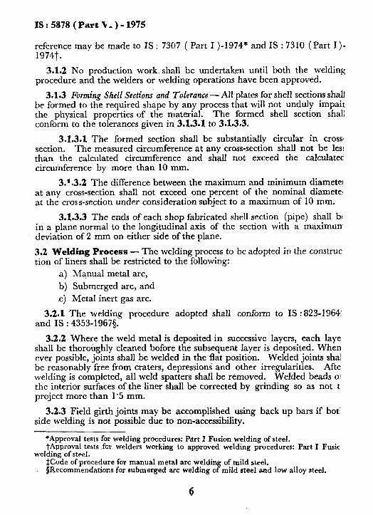
3.1.2 No production work. shall be undertaken until both the welding procedure and the welders or welding operations have been approved.
3.1.3 Forming Shell Sections and Tolerance - All plates for shell sections shall be formed to the required shape by any process that will not unduly impair the physical properties of the material. The formed shell section shal conform to the tolerances given in 3.X.3.1 to 3.1.3.3.
3.1.3.1 The formed section shall be substantially circular in cross section. The measured circumference at any cross-section shall not be les: than the calculated circumference and shall not exceed the calculatec circumference by more than 10 mm.
3.1.3.2 The difference between the maximum and minimum diameter at any cross-section shall not exceed one percent of the nominal diamete: at the cross-section under consideration subject to a maximum of 10 mm.
3.1.3.3 The ends of each shop fabricated shell section (pipe) shall bc in a plane normal to the longitudinal axis of the section with a maximun deviation of 2 mm on either side of the plane.
3.2 Welding Process - The welding process to be adopted in the construe tion of liners shall be restricted to the following:
a) Manual metal arc,
b) Submerged arc, and c) Metal inert gas arc.
3.2.1 The welding procedure adopted shall conform to IS : 823-1964: and IS : 4353-1967s.
3.2.2 Where the weld metal is deposited in successive layers, each laye shall be thoroughly cleaned bofore the subsequent layer is deposited. When ever possible, joints shall be welded in the flat position. Welded joints sha! be reasonably free from craters, depressions and other irregularities. Afte welding is completed, all weld spatters shall be removed. Welded beads 0: the interior surfaces of the liner shall be corrected by grinding so as not t project more than 1’5 mm.
3.2.3 Field girth joints may be accomplished using back up bars if bot‘ side welding is not possible due to non-accessibility.
*Approval tests for welding procedures: Part I Fusion welding of steel. iApproval tests for welders working to approved welding procedures: Part I Fusic
welding of steel. ICode of procedure for manual metal arc weldi
T of mild steel.
$Recommendations for submerged arc welding o mild steel and low alloy steel.
6
IS:5878 (Pa&VI)-W5
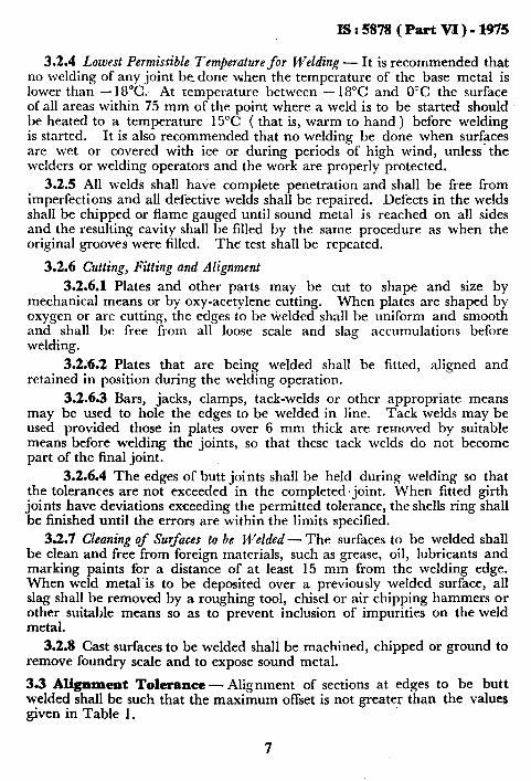
3.2.4 Lowest Permissible Temperature for Welding - It is recommended that no welding of any joint bedone when the temperature of the base metal is lower than - 18°C: At temperature between - 18°C and 0°C the surface of all areas within 75 mm of the point where a weld is to be started should be heated to a temperature 15°C ( that is, warm to hand ) before welding is started. It is also recommended that no welding be done when surfsces are wet or covered with ice or during periods of high wind, unless the welders or welding operators and the work are properly protected.
3.2.5 All welds shall have complete penetration and shall be free from imperfections and all defective welds shall be repaired. Defects in the welds shall be chipped or flame gauged until sound metal is reached on all sides and the resulting cavity shall be filled by the same procedure as when the original grooves were filled. The test shall be repeated.
3.2.6 Cutting, Fitting and Alignment
3.2.6.1 Plates and other parts may be cut to shape and size by mechanical means or by oxy-acetylene cutting. When plates are shaped by oxygen or arc cutting, the edges to be welded shall be uniform and smooth and shall bc free from all loose scale and slag accumulations before welding.
3.2.6.2 Plates that are being welded shall be fitted, aligned and retained in position during the weldmg operation.
3.2.6.3 Bars, jacks, clamps, tack-welds or other appropriate means may be used to hole the edges to be welded in line. Tack welds may be used provided those in plates over 6 mm thick are removed by suitable means before welding the joints, so that these tack welds do not become part of the final joint.
3.2.6.4 The edges of butt joints shall be held during welding so that the tolerances are not exceeded in the completed.joint. When fitted girth joints have deviations exceeding the permitted tolerance, the shells ring shall be finished until the errors are within the limits specified.
3.2.7 Cleaning of Surfaces to be Welded - The surfaces to be welded shall be clean and free from foreign materials, such as grease, oil, lubricants and marking paints for a distance of at least 15 mm from the welding edge. When weld metal’is to be deposited over a previously welded surface, all slag shall be removed by a roughing tool, chisel or air chipping hammers or other suitable means so as to prevent inclusion of impurities on the weld metal.
3.2.8 Cast surfaces to be welded shali be machined, chipped or ground to remove foundry scale and to expose sound metal.
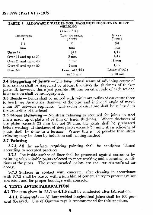
3.3 Alignment Tolerance - Alignment of sections at edges to be butt welded shall be such that the maximum offset is not greater than the values given in Table 1.
7
IS : 5878 (Part VI ) - 1975
--.p w---- TABLE 1 ALLOWABLE VALUES FOR MAXIMUM OFFSETS IN BUTT
WELDING
( Qause 3.3 )
THICKNESS LcNGrTl?n,INA~, GIRTFI
C:,
JOINTS JOINTS
(2) (3) mm mm mm
up to 12 l/4 t l/4 t
Over 12 and up to 20 3xGrn l/4 t Over 20 and up to 40 3mm 5mm
Over 40 and up to 50 3mm l/8 t
Over 50 Lesser of l/l6 t Lesser of l/8 t or 10 mm or 20 mm
3.4 Staggering of Joints - The longitudinal seams of adjoining course of liner section shall be staggered by at least five times the thickness of thicker plate. If, however, this is not possible 100 mm on either side of each welded inter-section shall be radiographed. 3.5 Bends - Bends shall be mitred with minimum radius of curvature three to five times the internal diameter of the pipe and included angle of maxi- mum 10’ between segments. The radius of curvature shall be referred to the centreline of the bend.
3.6 Stress Relieving - No stress relieving is required for joints in steel liners made up of plates of 32 mm or lesser thickness. Where thickness of the plates exceeds 32 mm but not 38 mm, the joints shall be preheated before welding. If thickness of steel plates exceeds 38 mm, stress relieving of joints shall be done in a furnace. Where this is not possible then stress relieving may be done by induction coil heating method.
3.7 Painting
3.7.1 All the surfaces requiring painting shall be sand/shot blasted according to accepted practices.
3.7.2 The inside surface of liner shall be protected against corrosion by painting with suitable paints selected to meet working and operating condi- tions of the pipes. The recommended paints are coal tar enamel/coal tar epoxy.
3.7.3 Surfaces in contact with concrete, after cleaning in accordance with 3.7.1 shall be coated with a thin film of cement slurry to protect against corrosion and for proper bondage with concrete.
4. TESTS AFTER FABRICATION
4.1 The tests given in 4.1.1 to 4.1.3 shall be conducted after fabrication.
4.1.1 Radiography - All butt welded longitudinal joints shall be 100 per- cent X-rayed. Use of Gamma rays is recommended for thicker plates,
IS : 5878 ( Part VI ) - 1975
4.t.2 Ultrasonic Tests - All butt welded girth joints shall be 100 percent ultrasonically tested.
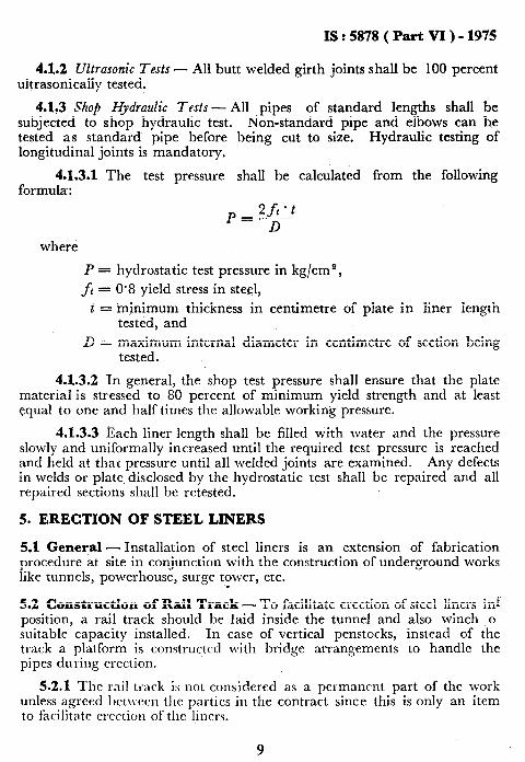
4.1.3 Shop Hydraulic Tests- All pipes of standard lengths shall be subjected to shop hydraulic test. tested as standard pipe before longitudinal joints is mandatory.
4.1.3.1 The test pressure formula:
&&standard pipe and elbows can be being cut to size. Hydraulic testing of
shall be calculated from the following
where
P = hydrostatic test pressure in kg/cme,
ft = 0.8 yield stress in ste1,
t = tiinimum thickness in centimetre of plate in liner length tested, and
B = maximum internal diameter in centimetre of section being tested.
4.1.3.2 In general, the shop test pressure shall ensure that the plate material is stressed to 80 percent of minimum yield strength and at least equal to one and half times the allowable working pressure.
4.1.3.3 Each liner length shall be filled with water and the pressure slowly and uniformally increased until the required test pressure is reached and held at that pressure until all welded joints arc examined. Any defects in welds or plate, disclosed by the hydrostatic test shall be repaired and all repaired sections shall bc retested.
5. ERECTION OF STEEL LINERS
5.1 General - Installation of steel liners is an extension of fabrication procedure at site in conjunction with the construction of underground works like tunnels, powcrhousc, surge tower, etc. W
5.2 Construction of Rail Track - To facilitate erection of steel liners inf position, a rail track should be laid inside the tunnel and also winch o suitable capacity installed. In case of vertical penstocks, instead of the track a platform is constructed with bridge arrangements to handle the pipes during erection.
5.2.1 The rail track is not considered as a pcrmancnt part of the work unless agreed bchvcen the partics in the contract since this is only an item to facilitate crcction of tllc liners.
9
IS:5878(PartVI)-1975
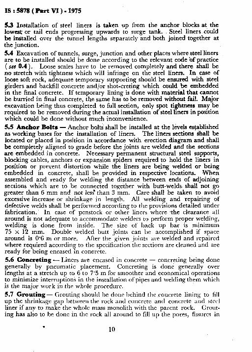
53 Installation of steel liners is taken up from the anchor blocks at the low* or tail ends progressing upwards to surge tank. Steel liners could be installed over the tunnel lengths separately and both joined together at the junction. 5.4 Excavation of tunnels, surge, junction and other places where steelliners are to be installed should be done according to the relevant code ‘of practice ( see 0.4 ). Loose scales have to be removed completely and there shall be no stretch with tightness which will infringe on the steel liners. In case of loose soft rock, adequate temporary supporting should be ensured with steel girders and backfill concrete and/or shot-creting which could be embedded in the final concrete. If temporary lining is done with material that cannot be burried in final concrete, the same has to be removed without fail. Major excavation being thus completed to full section, only spot tightness may be required to be removed during the actual installation of steel liners in position which could be done without much inconvenience.
5.5 Anchor Bolts - Anchor bolts shall be installed at the levels established as working bases for the installation of liners. The liners sections ‘shall be located or placed in position in accordance with erection diagram and shall be completely aligned to grade before the joints are welded and the sections are embedded in concrete. Necessary permanent structural steel supports, blocking cables, anchors or expansion spiders required to hold the liners in position or prevent distortion while the liners_ are being welded or being embedded in concrete, shall be provided in respective locations. When assembled and ready for welding the distance between ends of adjoining sections which are to be connected together with butt-welds- shall not go greater than 6 mm and not less’ than 3 mm. Care shall be taken to avoid excessive increase or shrinkage in length. All welding and repairing of defective welds shall be performed according to the provisions detailed under fabrication. In case of penstock or other liners where the clearance all around is not adequate to accommodate welders to perform proper welding, welding is done from inside. The size of back up bar is minimum 75 x 12 mm. Double welded butt joints can be accomplished if space around is 0’6 m or more. After the given -joints are welded and repaired where required according to the specification tire sections are cleaned and are ready for being encased in concrete. 5.6 Concreting - Liners are encased in concrete - concreting being done generally by pneumatic placement. Concreting is done generally over lengths at a stretch up to 6 to 7.5 m for smoother and economical operations to minimize interruptions in the installation ofpipes and welding them which is the major work in the whole procedure. 5.7 Grouting- Grouting sl~oulcl he done behind the .coucrete lining to fill up the shrinkage gap between the rock ant1 concrctc and concrctc and steel liner if any to make the whole mass monolith with the parent rock. Crout- ing has also to be done in the rock all around to fill up the pores, fissures in
IS:5878 (Part VI)-1975
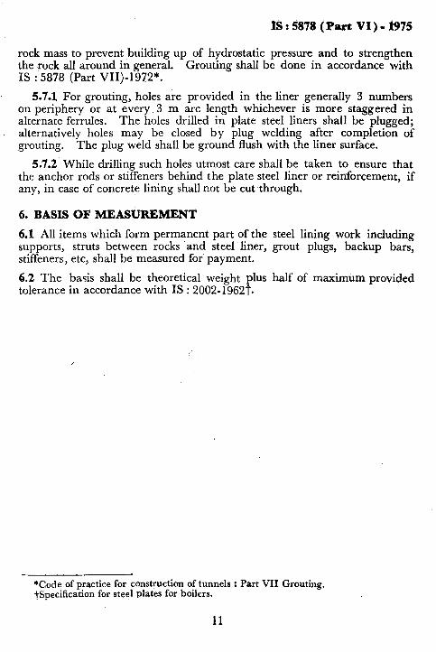
rock mass to prevent building up of hydrostatic pressure and to strengthen the rock all around in general. Grouting shall be done in accordance with IS : 5878 (Part VII)-1972*.
5.7.1 For grouting, holes are provided in the liner generally 3 numbers on periphery or at every 3 m arc length whichever is more staggered in alternate ferrules. The holes drilled in plate steel liners shall be plugged; alternatively holes may be closed by plug welding after completion of grouting. The plug weld shall be ground flush with the liner surface.
5.7.2 While drilling such holes utmost care shall be taken to ensure that the anchor rods or stiffeners behind the plate steel liner or reinforcement, if any, in case of concrete lining shall not be cut through.
6. BASIS OF MEASUREMENT
6.1 All items which form permanent part of the steel lining work including supports, struts between rocks and. steel liner, grout plugs, backup bars, stiffeners, etc, shall be measured for payment.
6.2 The basis shall be theoretical weight plus half of maximum provided tolerance in accordance with IS : 2002-1962t.
*Code of practice for construction of tunnels : Part VII Grouting. tspecification for steel plates for boilers.
11
BUREAU OF INDIAN STANDARDS
Headquarters:
Manak Bhavan, 9 Bahadur Shah Zafar Marg, NEW DELHI 110002
Telephones: 331 01 31, 331 13 75 TmManaksanstha ( Common to all Off ices )
Regional Offices:
Central : Manak Bhti&., 9 Bahadur Shah Zafar Marg, Telephone
I
331 01 31 NEW DELHI li 0002 331 13 75
+Egstern : l/l 4 C. I. T. Scheme VII M, V. I. P. Road, 36 24 99 Maniktola, CALCUTTA 700054
Nor\hern : SC0 445-446, Sector 35-C,
I
2 18 43 CHANDIGARH 160036 3 1641
(
41 24 42 Southern : C. I. T. Campus, MADRAS,6001 13 41 25 19 \
41 2916 twestern : Manakalaya, E9 MIDC, Marol, Andheri ( East ), 6 32 92 95
BOMBAY 400093
Branch Offices:
‘Pushpak’. Nurmohamed Shaikh Marg, Khanpur.
I
2 63 48 AHMADABAD 380001 2 63 49
+,Peenya lndust rial Area 1 st Stage, Bangalore Tumkur Road BANGALORE 560058
Gangotri Complex, 5th Floor, Bhadbhada R‘oad, T. T. Nagar, I
38 49 55 38 49 56 6 67 16
BHOPAL 462003 Plot No. 82/83. Lewis Road, BHUBANESHWAR 751002 53i5. Ward No. 29, R.G. Barua Road, 5th Byelane,
GUWAHATI 781003
5 36 27 3 31 77
5-8-56C L. N. Gupta Marg ( Nampally Station Road ), HYDERABAD 500001
23 1083
R14 Yudhister Marg, C Scheme, JAIPUR 302005
1171418 B Sarvodaya Nagar, KANPUR 208005
Patliputra Industrial Estate, PATNA 800013 T.C. No. 14/l 421. Universitv P.O.. Palayam
TRIVANDRUM 695035
{ 6 34 71 6 98 32
I ;: :: if 6 23 05
/6 21 04 16 21 17’
Mspection Offices ( With Sale Point ):
Pushpanjali, First Floor, 205-A West High Court Road, 2 51 71 Shankar Nagar Square, NAGPUR 440010
institution of Engineers ( India ) Building, 1332 Shivaji Nagar, 5 24 35 PUNE 411005
*Sales Office in Calcut!a is at 5 Chowringhee Approach, P. 0, Princep 27 68 00 Street. Cakutra 700072
tSalas Office in Bombay is at Novelty Chambers, Great Road, 89 66 29 Bombay 400007
$Sales Office in Bangalore is at Unity Building, Narasimharaje $quar;;22 39 71 Bangalore 560002
Reprography Unit, BIS, New Delhi, India
AHENDMENT NO. 1 n*CH 1977
TO
IS:5878(Part VI)-1975 CODE OF PRACTICE FOR CONSTRUCTION OF TUNNELS
PART VI STEEL LINIfiG
Alteration
: (Pirot uover page, pages I and 3, title) - Substitute the followin& fol' the exl8ting title:
‘Indian Standard CODE OF PRACTICE FOR COBSTRUCTIOI
OF TUlJlELS COBVEYIlG WATER
PART VI STEEL LIEIXG'
(BDc 58)
Reprography Unit, BIS, New Delhi, India