isa seminars on the web live experts on hot topics
TRANSCRIPT

© 2011, ISA EN00W4 (1.4)
Standards
Certification
Education and Training
Publishing
Conferences and Exhibits
ISA Seminars on the Web Live Experts on Hot Topics
Standards
Certification
Education and Training
Publishing
Conferences and Exhibits
CSE PE Exam Review:
Control Systems
EN00W4 Version 1.4
© 2011

© 2011, ISA EN00W4 (1.4)
Seminar Logistics
• Seminar materials
– Downloadable presentation
– Question and Answer session (audio and email)
– Survey
– Earn 1 Professional Development Hour (PDH)
• Seminar length
– 60 minute presentation
– Three 10-minute question and answer sessions
Audio Instructions
• As a participant, you are in a “listen-only” mode.
• You may ask questions via the internet, using your keyboard, at any time during the presentation. However, the presenter may decide to wait to answer your question until the next Q&A Session.
• If you have audio difficulties, press *0.

© 2011, ISA EN00W4 (1.4)
Audio Instructions for Q&A Sessions
• Questions may be asked via your telephone line.
• Press the *1 key on your telephone key-pad.
• If there are no other callers on the line, the operator will announce your name and affiliation to the audience and then ask for your question.
• If other participants are asking questions, you will be placed into a queue until you are first in line.
• While in the queue, you will be in a listen-only mode until the operator indicates that your phone has been activated. The operator will announce your name and affiliation and then ask for your question.
Introduction of Presenter
• Gerald Wilbanks, P.E. Vice President of Documentation and Engineering Services in Birmingham, Alabama has over 40 years of experience in engineering, management, consulting, and design in heavy industry. He is a registered professional engineer in 4 states, a member of NSPE, ASQ, and an International Former President (1995) of ISA. Gerald is a graduate of Mississippi State University with a Bachelors Degree in Electrical Engineering and was recognized as the Engineer of the Year in 1991 by the Engineering Council of Birmingham. He is a Distinguished Engineering Fellow of Mississippi State University and is a Life Fellow member of ISA. He has served as an instructor in many courses, seminars, and other educational sessions for ISA and in his own business.

© 2011, ISA EN00W4 (1.4)
Key Benefits of Seminar
• Identify areas of focus for more effective studying to assist inpassing the PE examination
• Explain control system functionality
• List Control System applications
• Discuss system documentation and standards used
• Review Control Loop Tuning
• Control Systems represents 18 problems or 22% of the CSE PE exam
Section 1: Control Loops
• Loop Definitions
• Controller Actions
• Loop Examples
• Proportional Mode
• Integral Mode
• Derivative Mode
• Controller Characteristics

© 2011, ISA EN00W4 (1.4)
Process Control
• The regulation or manipulation of variables influencing the conduct of a process in such a way as to obtain a product of desired quality and quantity in an efficient manner
PROCESSMANIPULATED
VARIABLESMEASURED
VARIABLE
CONTROLLER
CONTROLLED
VARIABLE
DISTURBANCES
The Process Control System (Loop)
PROCESS
TRANSMITTED
SIGNAL
SENSOR
TRANSMITTERCONTROLLER
FINAL CONTROLELEMENT
MANIPULATED
VARIABLE
CONTROLLED
VARIABLE
SET POINT
Signal basedon error ordeviation and effects of controlmodes

© 2011, ISA EN00W4 (1.4)
Controller Actions and Modes
• Direct and reverse actions
• On-Off control
• Proportional control
• Integral control
• Derivative control
CORPORATE LEVEL CONTROLS
SCHEDULING AND OTHER
Ratio, Cascade, Feedforward
ADVANCED REGULATORY CONTROL
Feedback
BASIC REGULATORY CONTROL
OPTIMIZATION
SAFETY CONTROLS
PROCESS
Control Hierarchy

© 2011, ISA EN00W4 (1.4)
Controllers and Control Strategies
Set Point
Disturbances
Process Measurement
Algorithm(Control Law)
FinalControlElement
ProcessΣΣΣΣ
Controller Output
Direct Acting Controller
CONTROLLAW
ErrorSet Point
Measurement
ControllerOutput
Increase in MeasurementCauses
Increase in Controller Output
ΣΣΣΣ

© 2011, ISA EN00W4 (1.4)
Reverse Acting Controller
CONTROLLAW
ErrorSet Point
Measurement
ControllerOutput
Increase in MeasurementCauses
Decrease in Controller Output
ΣΣΣΣ
Direct or Reverse Acting - Example
Steam
Air-to-Open

© 2011, ISA EN00W4 (1.4)
Proportional Control
Proportional Control Algorithm
Gain
Closed
Open
Setpoint
Valve
100
90
80
70
60
50
40
30
20
100
m = Kce + Bias
e
KC
KCe
e m
Proportional Action
• Proportional band
– The amount of input change that will produce 100% output change.
– Always expressed as a percentage
• Gain
– A unit-less number that defines the ratio of the change in output, due to
proportional control action, to the change in input
PB G
200% --------------------------------- .5
100% -----------------------------------1
50% ------------------------------------2
in
outG
∆
∆=
PBG
100=

© 2011, ISA EN00W4 (1.4)
Integral Action
• Integral (reset):
– Control action in which the output is proportional to the time
integral of the input
– Reset action is adjusted in repeats/minutes or minutes/repeat
Minutes/Repeat (Ti) Repeats/Minute (Tr)
2 ------------------------- .5
1 ------------------------- 1
.5 ------------------------- 2
Proportional + Integral Control
Proportional - Plus - Integral (PI):
Integral (Reset) Action: mT
edt
i
= ∫1
BiasdteT
eKm
i
c+
+= ∫
1
Gain
Closed
Open
Setpoint
Valve
100
90
80
70
60
50
40
30 20
10 0
Reset

© 2011, ISA EN00W4 (1.4)
Derivative Action
• Derivative (rate):
– Control action in which the output is proportional to the rate of change in the input
Derivative (Rate) Control Action
m Td
dte
d=
Control action in which the output is proportionalto the rate of change in the input
Error Signal-5
0
+5
75¡
80¡
85¡ Temperature
Rate of Change Over Time

© 2011, ISA EN00W4 (1.4)
Proportional + Integral + Derivative Control
Gain
Closed
Open
Setpoint
Valve
10090807060
50403020100
Reset
Rate
P + I + D + Biasm K eT
edt Td
dte
c
i
d= + +
∫
1
edt
dT Action (Rate) Derivative D ==m
Characteristics of Controller Modes
• Proportional
– Simple
– Inherently stable when properly tuned
– Easy to tune
– Experiences offset at steady state
• Proportional-plus-reset
– No offset
– Better dynamic response than reset alone
– Possibilities exist for instability due to lag introduced

© 2011, ISA EN00W4 (1.4)
Characteristics of Controller Modes (cont’d)
• Proportional-plus-rate
– Stable
– Less offset than proportional alone (use of higher Kc possible)
– Reduces lags, i.e., more rapid response
• Proportional-plus-reset-plus-rate
– Most complex
– Rapid Response
– No offset
– Difficult to tune
– Best control if properly tuned
Process Dynamics (Response to Change)
INPUT CHANGE OUTPUT RESPONSE
PROCESSDEAD TIME PLUS
FIRST ORDER LAG

© 2011, ISA EN00W4 (1.4)
Dead Time
DEAD TIME
CHANGEIN INPUT
INPUT CHANGE INITIATED
PROCESS
Process Variable Measurement
Time
Time Constant
FIRST TIMECONSTANT
TIME
100%
63.2%
0%
CHANGE IN INPUT
PROCESS
OU
TP
UT
CH
AN
GE
%
Process Variable Measurement

© 2011, ISA EN00W4 (1.4)
First Order Lag
0 1 2 3
TIME CONSTANTS
INPUT
OUTPUT
4 5
Input
Output
Dead Time
Product Out
Td
TIC
Steam
Product In
Condensate
Time
Steam In
Outlet Temperature

© 2011, ISA EN00W4 (1.4)
First Order Lag plus Dead Time
0 1 2 3
TIME CONSTANTS
INPUT
OUTPUT
4
Td
Tuning Methods
• Objectives of Tuning
• Trial & error
• Open-loop test
• Closed-loop test
• Improving “as found” tuning

© 2011, ISA EN00W4 (1.4)
Objectives of Tuning
• Adjustment of gain, reset, and rate to achieve “good” process
control
CHANGE / DISTURBANCE
PROCESS
CONTROLSYSTEM
GOOD PROCESS CONTROL
Acceptable response to a set point change
1. ONE-QUARTER DECAY RATIO
A BB
A
1
4
2. MINIMIZE OVERSHOOT
Objectives of Tuning (cont’d)
© 2011, ISA EN00W4 (1.4)
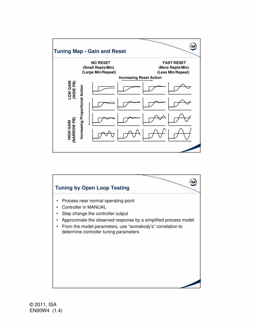
Tuning Map - Gain and Reset
Increasing Reset Action
FAST RESET
(More Repts/Min)
(Less Min/Repeat)
NO RESET
(Small Repts/Min)
(Large Min/Repeat)
Inc
rea
sin
g P
rop
ort
ion
al
Ac
tio
n
HIG
H G
AIN
(NA
RR
OW
PB
)L
OW
GA
IN(W
IDE
PB
)
Tuning by Open Loop Testing
• Process near normal operating point
• Controller in MANUAL
• Step change the controller output
• Approximate the observed response by a simplified process model
• From the model parameters, use “somebody’s” correlation to determine controller tuning parameters

© 2011, ISA EN00W4 (1.4)
Z-N Open Loop Test Method
TIMEττττTd
K = PROCESS GAIN =p
T =d DEAD TIME
ττττ TIME CONSTANT
Tangent - drawn at pointof steepest process rise
VALVE∆∆∆∆
MEAS∆∆∆∆
VALVE∆∆∆∆
MEAS∆∆∆∆ 63.2%MEAS∆∆∆∆
=
=
=
Open Loop Method (cont’d)
TUNING PARAMETERS
P PI PID
K
T
T
I
D
Cττττ
K Tp d
ττττK Tp d
ττττK Tp d
0.9 1.2
3.33 Td 2.0 Td
0.5 Td
(Gain)
(Minutes/Repeat)
(Minutes)

© 2011, ISA EN00W4 (1.4)
Problems with Open Loop Method
• Sensitive to parameter estimation error (especially dead time)
• Simplified form of process model may not match the actual process
• Controller not in normal operating mode
• Limitations on step size may make it difficult to interpret the response - especially in the presence of noise
• Closed loop response may not be acceptably damped for a set point change
Tuning by Closed Loop Testing
• Process near normal operating point
• Controller in AUTOMATIC
• GAIN only; no RESET nor DERIVATIVE
• Induce sustained oscillation by gradually increasing controller gain
• Note the ultimate period (Pu) and ultimate gain (Kcu)
• Use correlation to determine controller tuning parameters

© 2011, ISA EN00W4 (1.4)
Z-N Closed Loop Method
uP
Increase Kc
Decrease Kc
K = Kcu c
Closed Loop Method (cont’d)
TUNING PARAMETERS
P PI PID
K
T
T
I
D
C 0.6 K cu
0.83 P 0.5 P
0.125 P
u u
u
0.45 K cu0.5 K cu
(Gain)
(Minutes/Repeat)
(Minutes)

© 2011, ISA EN00W4 (1.4)
Problems with Closed Loop Method
• May not be possible to drive process into oscillating condition
• May require several tests - longer testing time - than open loop method
• Cannot guarantee how much the PV - nor the controller output - will “swing”
Good Points with Closed Loop Test
• Controller is operating in its normal mode (automatic)
• No artificial form of the process model imposed
• Minimal uncertainty in the data

© 2011, ISA EN00W4 (1.4)
Review of Key Points
• The controller action works together with the control valve operation
• Controller law or algorithm determines the output from the controller in response to loop error
• Control modes must be selected based on the process characteristics and response
• Three mode control is not always the most effective selection
• The control modes are interactive and dynamic
Live Question and Answer Session
• During Q&A, questions may be asked via your telephone line.
• Press the *1 key on your telephone key-pad.
• If there are no other callers on the line, the operator will announce your name and affiliation to the audience and then ask for your question.
• If other participants are asking questions, you will be placed into a queue until you are first in line.
• While in the queue, you will be in a listen-only mode until the operator indicates that your phone has been activated. The operator will announce your name and affiliation and then ask for your question.

© 2011, ISA EN00W4 (1.4)
Section 2: System Documentation
• Process and Instrument Diagrams
• ISA Standards for Documentation
• Loop Numbering Conventions
• Loop Diagram Symbology
• Instrument Lists
• Installation Details
Process and Instrumentation Diagram
FIC
FIC
PIC
LIC
VENT
FEED
O2
FIFCV
FCVLCV
PCV
© 2011, ISA EN00W4 (1.4)
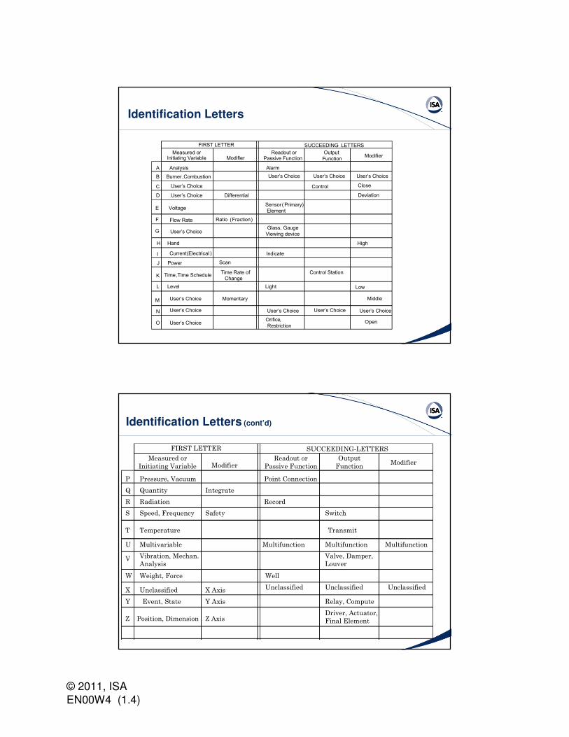
Identification Letters
FIRST LETTER SUCCEEDING- LETTERS
Measured orInitiating Variable Modifier
A
B
C
D
E
F
G
H
I
J
K
L
M
N
O
Analysis
Burner, Combustion
User’s Choice
User’s Choice
Voltage
Flow Rate
User’s Choice
Hand
Current (Electrical )
Power
Time, Time Schedule
Level
User’s Choice
User’s Choice
User’s Choice
Differential
Ratio (Fraction)
Scan
Time Rate of
Change
Momentary
Readout orPassive Function
Alarm
User’s Choice
Sensor (Primary)
Element
Glass, Gauge
Viewing device
Indicate
Light
User’s Choice
Orifice,
Restriction
Output
Function
User’s Choice
Control
Control Station
User’s Choice User’s Choice
User’s Choice
Modifier
High
Low
Close
Deviation
Middle
Open
Identification Letters (cont’d)
FIRST LETTER SUCCEEDING-LETTERS
Measured or
Initiating Variable ModifierReadout or
Passive Function
Output
FunctionModifier
P Pressure, Vacuum Point Connection
Q Quantity Integrate
R Radiation Record
S Speed, Frequency Safety Switch
T Temperature Transmit
U Multivariable Multifunction Multifunction Multifunction
V Vibration, Mechan.
Analysis
Valve, Damper,
Louver
W Weight, Force Well
X Unclassified X Axis Unclassified Unclassified Unclassified
Y Event, State Y Axis Relay, Compute
Z Position, Dimension Z AxisDriver, Actuator,
Final Element
© 2011, ISA EN00W4 (1.4)
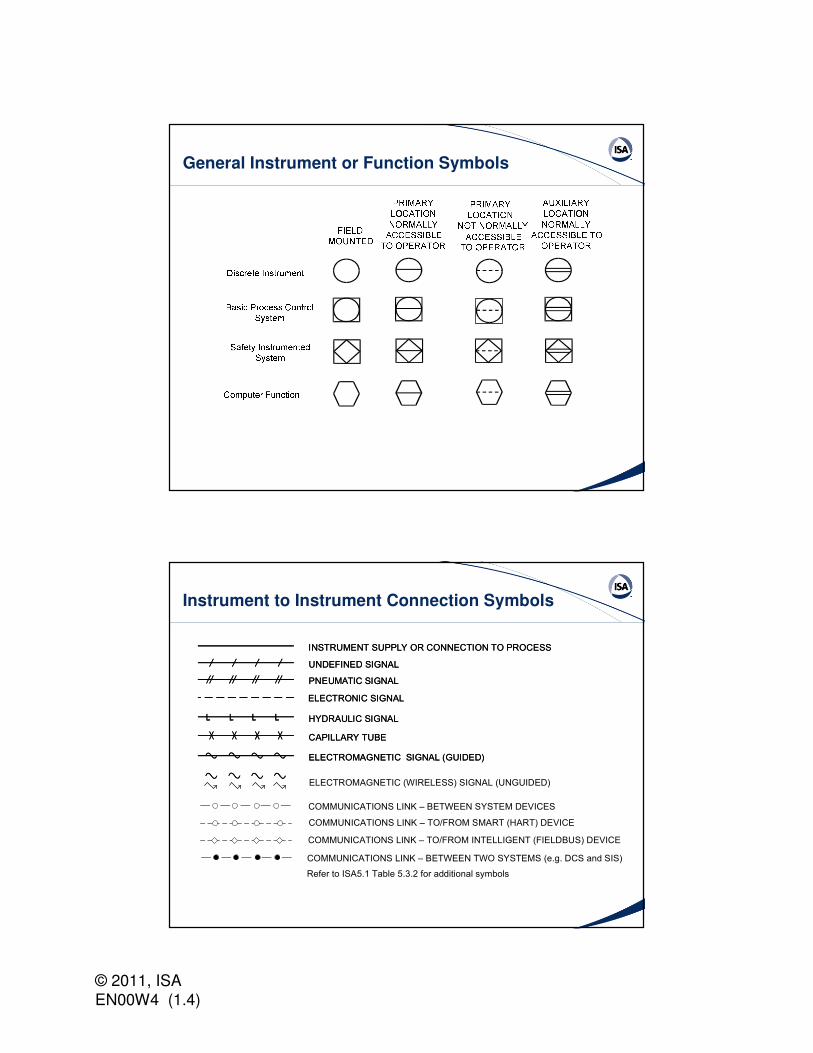
General Instrument or Function Symbols
Instrument to Instrument Connection Symbols
INSTRUMENT SUPPLY OR CONNECTION TO PROCESS
UNDEFINED SIGNAL
PNEUMATIC SIGNAL
ELECTRONIC SIGNAL
CAPILLARY TUBE
HYDRAULIC SIGNAL
ELECTROMAGNETIC SIGNAL (GUIDED)
INSTRUMENT SUPPLY OR CONNECTION TO PROCESS
UNDEFINED SIGNAL
PNEUMATIC SIGNAL
ELECTRONIC SIGNAL
CAPILLARY TUBE
HYDRAULIC SIGNAL
ELECTROMAGNETIC SIGNAL (GUIDED)
COMMUNICATIONS LINK – BETWEEN SYSTEM DEVICES
COMMUNICATIONS LINK – TO/FROM SMART (HART) DEVICE
COMMUNICATIONS LINK – TO/FROM INTELLIGENT (FIELDBUS) DEVICE
ELECTROMAGNETIC (WIRELESS) SIGNAL (UNGUIDED)
COMMUNICATIONS LINK – BETWEEN TWO SYSTEMS (e.g. DCS and SIS)
Refer to ISA5.1 Table 5.3.2 for additional symbols
© 2011, ISA EN00W4 (1.4)
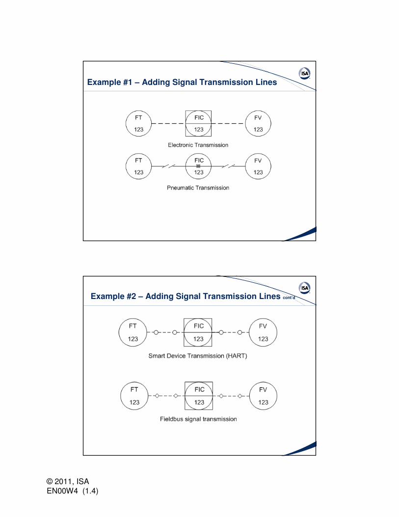
Example #1 – Adding Signal Transmission Lines
Example #2 – Adding Signal Transmission Lines cont’d

© 2011, ISA EN00W4 (1.4)
Actuator Action and Power Failure
Flow Measuring Element Symbols
Orifice plate or restriction orifice
Pitot tube
Turbine flowmeter
Vortex shedding flowmeter
b)Ma) Magnetic flowmeter
∆T a) b) Thermal mass flowmeter
Positive displacement flowmeter
Cone flowmeter
Coriolis mass flowmeter
Sonic flowmeter
Open channel flowmeter
Refer to ISA5.1 Table 5.2.3 for additional symbols

© 2011, ISA EN00W4 (1.4)
Level Measuring Element Symbols
Displacer internally mounted in vessel
Ball float internally mounted in vessel
Sonic or Single point Radiation
Dip Tube and other primary element
Probe inserted in vessel
Radar
Refer to ISA5.1 Table 5.2.3 for additional symbols
Typical Transmitters – Flow
Orifice plate and orifice flanges withflange taps, differential pressure transmitter, pneumatic transmission
Orifice plate andflanges, taps aremade in pipe,differential pressuretransmitter, electronictransmission
Venturi tube, tapsare in tube, differential pressuretransmitter withindicator, electronictransmission
Pitot tube, connections are in tube, differentialpressure transmitter,electronic transmission
FE99
FT99
FE1
FT1
FE100
FIT100
FT15
FE15

© 2011, ISA EN00W4 (1.4)
Level using Differential Pressure Transmitter
Differential pressure typetransmitter, electronicsignal
VESSELLIT99
ISA Standards used for Documentation
• ISA5.1-2009, Instrumentation Symbols and Identification
• ISA5.4-1991, Instrument Loop Diagrams
• ISA5.5-1985, Graphic Symbols for Process Displays

© 2011, ISA EN00W4 (1.4)
Other Documentation
• Loop diagrams
• Process flow diagrams
• Instrument lists
• Instrument installation
• Piping specifications
Review of Key Points
• Control systems can be documented in a logical and standard manner
• Each drawing has a specific purpose and conveys information to avariety of people
• The P&I Diagram is the central most important document to portray the overall control function
• Calculations and device selection is based on the documents for the system function

© 2011, ISA EN00W4 (1.4)
Live Question and Answer Session
• During Q&A, questions may be asked via your telephone line.
• Press the *1 key on your telephone key-pad.
• If there are no other callers on the line, the operator will announce your name and affiliation to the audience and then ask for your question.
• If other participants are asking questions, you will be placed into a queue until you are first in line.
• While in the queue, you will be in a listen-only mode until the operator indicates that your phone has been activated. The operator will announce your name and affiliation and then ask for your question.
Section 3: Control Types/Characteristics
• Ratio control
• Cascade control
• Feedforward control

© 2011, ISA EN00W4 (1.4)
Ratio Control - Wild Stream
• RATIO CONTROL:
Flow rate of one stream paces the flow rate of a second stream
FFC
FT
FT
Wild Flow
FY
FY
Controlled
Flow
Ratio Control - Both Streams Controlled
Air
Hydrocarbon
Air
MIXINGTEE TO
REACTOR
FC
F F
F C

© 2011, ISA EN00W4 (1.4)
Automatic Ratio Set: Example
TT
TICFC
FTFT
FC
O C2 O T2
AIR FUEL
Cascade Control: Diagram
• CASCADE CONTROL:
When one feedback controller
sets the set point of another feedback controller
FIC
FT
TIC
Primary
Controller
Secondary
Controller
FY
TT
© 2011, ISA EN00W4 (1.4)
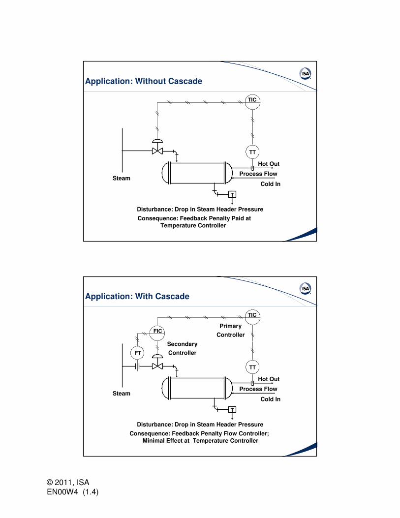
Application: Without Cascade
TIC
T
SteamCold In
Hot Out
Process Flow
TT
Disturbance: Drop in Steam Header Pressure
Consequence: Feedback Penalty Paid at
Temperature Controller
Application: With Cascade
FIC
FT
TIC
Primary
Controller
Secondary
Controller
T
SteamCold In
Hot Out
Process Flow
TT
Disturbance: Drop in Steam Header Pressure
Consequence: Feedback Penalty Flow Controller;
Minimal Effect at Temperature Controller

© 2011, ISA EN00W4 (1.4)
Inner and Outer Loops
Primary Secondary InnerProcess
MainProcess
Disturbance Disturbance
INNER LOOP
OUTER LOOP
Σ Σ
Feedforward Control: Definition
FEEDFORWARD CONTROL:
The final control device (valve or set point of lower level flow controller) is manipulated by a measurement of the process disturbance, rather than by the output of a feedback controller

© 2011, ISA EN00W4 (1.4)
Feedforward Control: Requirements
• The disturbance must be measurable
• We must know what to do to compensate for the disturbance
• We must know when (i.e., on what time schedule) to take the compensating action
Feedforward Control Loop (cont’d)
SETPOINTDISTURBANCE
FEEDFORWARDCONTROLLER
SENSOR
PROCESSMANIPULATED CONTROLLED
VARIABLE VARIABLE

© 2011, ISA EN00W4 (1.4)
Feedforward Control of Heat Exchanger
LIQUID IN
LIQUID OUT
STEAM
FC
FI
TRC
TI
TRAP
T
T
W
F
T
T
T
SP
SP
SP
0
F =Wc ( )
H∆
T – TSPP ii
ADJUSTING THE SETPOINT
Level Control Strategy – Functional Diagram
LT
T AA
PI
f(x)Feedwater Control
Valve (Valve A)
Steam Drum Level(Device C)
Single Element Control

© 2011, ISA EN00W4 (1.4)
Level Control Strategy – Functional Diagram
FT
T AA
SUM
f(x)
Feedwater Flow(Device B)
Three Element Control
PI
FTSteam Flow(Device E)
PI
LT
Steam Drum Level(Device C)
Feedwater ControlValve (Valve A)
Review of Key Points
• Blending and mixing can be done with ratio control systems
• Cascade control is when the output of one feedback controller isthe set point for another controller
• The inner loop of a cascade system should have a much faster speed of response than the primary control loop
• Feedforward control may be used with feedback control to provide correction in anticipation of a disturbance.

© 2011, ISA EN00W4 (1.4)
Live Question and Answer Session
• During Q&A, questions may be asked via your telephone line.
• Press the *1 key on your telephone key-pad.
• If there are no other callers on the line, the operator will announce your name and affiliation to the audience and then ask for your question.
• If other participants are asking questions, you will be placed into a queue until you are first in line.
• While in the queue, you will be in a listen-only mode until the operator indicates that your phone has been activated. The operator will announce your name and affiliation and then ask for your question.
How Many People Are at Your Site?
• Poll Slide
• Click on the appropriate number indicating the number of people that are at your site.

© 2011, ISA EN00W4 (1.4)
Sample Exam Question - #1
• According to ISA Standard 5.1, Instrumentation Symbols and Identification, the terms “record” or “recording” can apply to which of the following:
I. Graphical data in a strip or circular chart
II. A table of numerical data in a computer memory
III. A listing of alarms by a control computer
A. I and II
B. II and III
C. I and III
D. I, II, and III
Sample Exam Question - #2
• The control algorithm for a flow control loop is under consideration. It is determined that the flow must be maintained near set point with little or no offset and the signal will be rapid response and noisy. The best choice of control modes for this loop will be:
A. Proportional Mode
B. Integral plus Derivative
C. Proportional plus Integral
D. Proportional plus Integral plus Derivative
© 2011, ISA EN00W4 (1.4)
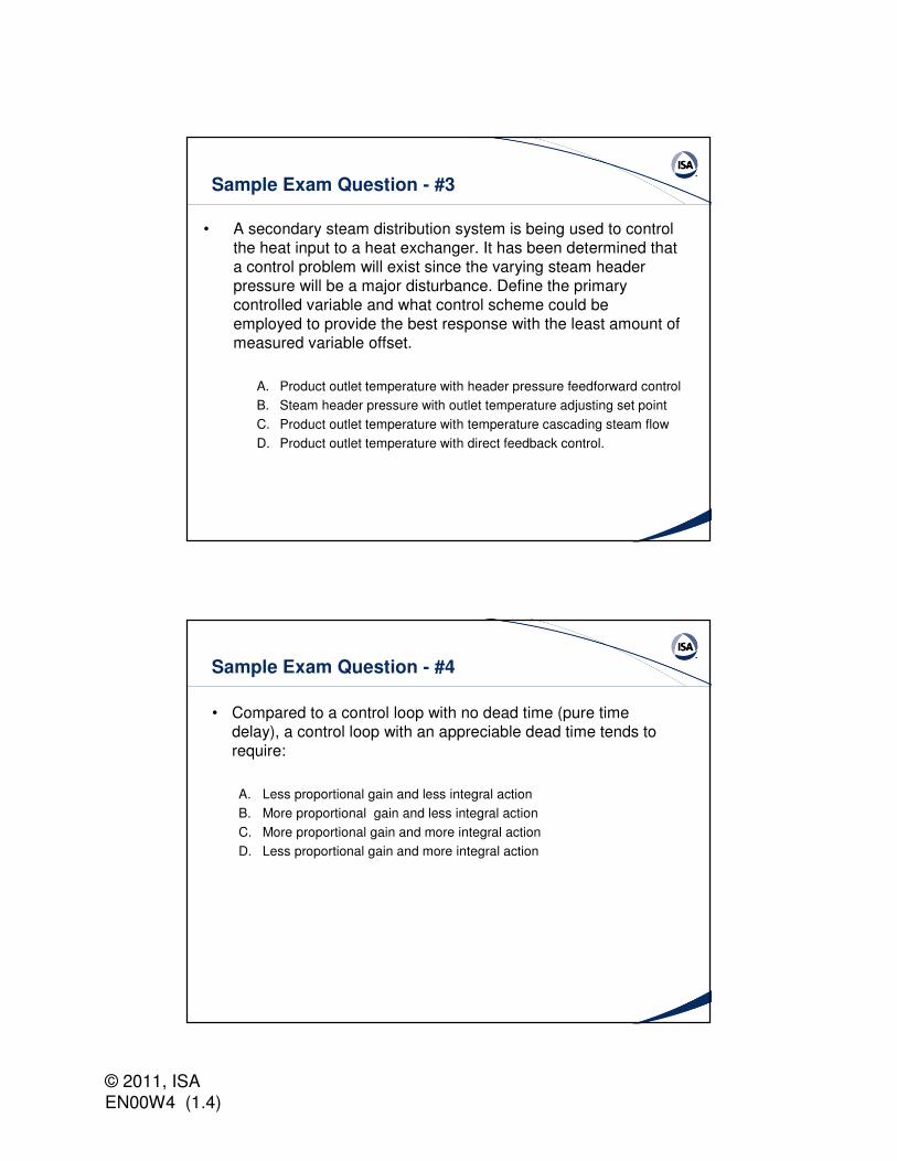
Sample Exam Question - #3
• A secondary steam distribution system is being used to control the heat input to a heat exchanger. It has been determined that a control problem will exist since the varying steam header pressure will be a major disturbance. Define the primary controlled variable and what control scheme could be employed to provide the best response with the least amount of measured variable offset.
A. Product outlet temperature with header pressure feedforward control
B. Steam header pressure with outlet temperature adjusting set point
C. Product outlet temperature with temperature cascading steam flow
D. Product outlet temperature with direct feedback control.
Sample Exam Question - #4
• Compared to a control loop with no dead time (pure time delay), a control loop with an appreciable dead time tends to require:
A. Less proportional gain and less integral action
B. More proportional gain and less integral action
C. More proportional gain and more integral action
D. Less proportional gain and more integral action

© 2011, ISA EN00W4 (1.4)
Related Courses from ISA
• Understanding and Applying Standard Instrumentation and Control Documentation (FG15)
• Tuning Advanced Controllers (TC05C2)
• Understanding Industrial Process Measurement and Control (FG05)
• All ISA courses are available any time as on-site training
• For more information: www.isa.org/training or (919) 549-8411
Other Related Resources from ISA
• Instrument Engineer’s Handbook, 3rd Edition (Bela Liptak) from ISA Press
• Fundamentals of Process Control Theory (Paul Murrill) from ISA Press
• The Condensed Handbook of Measurement and Control, 2nd
Edition (N. Battikha) from ISA Press
• ISA5.1-2009 – Instrumentation Symbols & Identification

© 2011, ISA EN00W4 (1.4)
Other Related Resources from ISA
• ISA Membership is just $100 per year, which includes free membership in two Technical Divisions (a $20 value) - one from each Department: Automation and Technology and Industries and Sciences.
– For more information: http://www.isa.org/membership/meminfo or (919) 549-8411
ISA Certifications
• Certified Automation Professionals ® (CAP ®)
– www.isa.org/CAP
• Certified Control Systems Technician® (CCST®)
– www.isa.org/CCST
• Please visit us online for more information on any of these programs, or call (919) 549-8411.

© 2011, ISA EN00W4 (1.4)
Please take our Web Seminar Surveyvia Zoomerang
The seminar survey was sent to you via email during the seminar. Please do not forget to complete the Zoomerang survey.