iseries experience reports: configuring management … · 2016-03-02 · most firewalls have this...
TRANSCRIPT
iSeries
Experience
Reports
Configuring
Management
Central
Connections
for
Firewall
Environments
���

iSeries
Experience
Reports
Configuring
Management
Central
Connections
for
Firewall
Environments
���

©
Copyright
International
Business
Machines
Corporation
2004.
All
rights
reserved.
US
Government
Users
Restricted
Rights
–
Use,
duplication
or
disclosure
restricted
by
GSA
ADP
Schedule
Contract
with
IBM
Corp.
Contents
Configuring
Management
Central
Connections
for
Firewall
Environments
. v
Chapter
1.
Terminology
.
.
.
.
.
.
.
. 1
Chapter
2.
Management
Central
Connections
.
.
.
.
.
.
.
.
.
.
.
.
. 3
C++
Infrastructure
.
.
.
.
.
.
.
.
.
.
.
. 4
CA++
Extensions
.
.
.
.
.
.
.
.
.
.
.
.
. 5
Java
Infrastructure
.
.
.
.
.
.
.
.
.
.
.
. 6
Java
Extensions
.
.
.
.
.
.
.
.
.
.
.
.
. 8
Host
Servers
.
.
.
.
.
.
.
.
.
.
.
.
.
. 9
Secure
Sockets
Layer
.
.
.
.
.
.
.
.
.
.
. 10
Connection
Configurations
.
.
.
.
.
.
.
.
. 11
Chapter
3.
Management
Central
Firewall
Quick
Reference
.
.
.
.
.
.
. 13
Chapter
4.
Management
Central
Limitations
due
to
Network
Address
Translation
.
.
.
.
.
.
.
.
.
.
.
.
. 15
Network
Address
Translation
(NAT)
.
.
.
.
.
. 15
Static
NAT
.
.
.
.
.
.
.
.
.
.
.
.
.
.
. 16
Dynamic
NAT
.
.
.
.
.
.
.
.
.
.
.
.
. 16
Management
Central
Limitations
.
.
.
.
.
.
. 16
Chapter
5.
Graphical
Client
Protected
by
a
Firewall
.
.
.
.
.
.
.
.
.
.
.
. 17
Warning:
Temporary
Level
2
Header
.
.
.
.
.
. 18
Firewall
that
is
not
using
NAT
.
.
.
.
.
.
. 18
Firewall
that
uses
Static
NAT
.
.
.
.
.
.
.
. 18
Firewall
that
uses
Dynamic
NAT
.
.
.
.
.
. 18
Chapter
6.
Central
System
Protected
by
a
Firewall
.
.
.
.
.
.
.
.
.
.
.
.
. 19
Firewall
that
is
not
using
NAT
.
.
.
.
.
.
.
. 20
Firewall
that
uses
Static
NAT
.
.
.
.
.
.
.
. 20
Firewall
that
uses
Dynamic
NAT
.
.
.
.
.
.
. 20
Chapter
7.
Endpoint
Systems
Protected
by
a
Firewall
.
.
.
.
.
.
.
.
.
.
.
. 21
Firewall
that
is
not
using
NAT
.
.
.
.
.
.
.
. 22
Firewall
that
uses
Static
NAT
.
.
.
.
.
.
.
. 22
Firewall
that
uses
Dynamic
NAT
.
.
.
.
.
.
. 23
©
Copyright
IBM
Corp.
2004
iii

iv
iSeries
Experience
Reports:
Configuring
Management
Central
Connections
for
Firewall
Environments
Configuring
Management
Central
Connections
for
Firewall
Environments
This
report
details
Management
Central
connections
and
the
configurations
required
to
enable
Management
Central
to
operate
within
a
variety
of
firewall
environments
as
of
v5r3.
As
a
distributed
management
application,
Management
Central
requires
numerous
incoming
and
outgoing
TCP/IP
socket
connections.
In
contrast,
the
basic
premise
of
a
firewall
is
to
restrict/modify
incoming
and
outgoing
connections.
To
assist
in
configuring
Management
Central
within
a
firewall
environment,
this
report
discusses
the
nature
and
orientation
of
Management
Central
connections
and
the
restrictions
of
specific
types
of
firewalls
that
limit
or
disable
some
Management
Central
connections.
Both
Static
Network
Address
Translation
(NAT)
and
Dynamic
NAT
will
be
discussed.
Three
basic
firewall
environments
will
be
described
along
with
the
configuration
required
to
enable
Management
Central
to
operate
properly
within
each
environment.
These
basic
environments
and
associated
configurations
are
intended
to
be
used
as
a
guide
to
enable
Management
Central
in
more
complex
firewall
environments.
Terminology
Defines
important
terms
that
will
be
used
throughout
this
report.
Management
Central
Connections
Describes
the
different
connections
that
are
made
between
the
Graphical
Client
and
the
Management
Central
servers.
Groups
the
applications
by
those
that
use
each
of
the
connections.
Management
Central
Firewall
Quick
Reference
A
chart
listing
the
ports
that
need
to
be
opened
in
your
firewalls
in
order
to
get
Management
Central
to
work
in
a
simple
case
(not
valid
if
network
address
translation
is
being
used).
Management
Central
Limitations
due
to
Network
Address
Translation
Describes
static
and
dynamic
network
address
translation
and
how
these
types
of
address
translation
affect
Management
Central.
Scenario
1
-
Graphical
Client
Protected
by
a
FirewallDetails
configuration
required
to
enable
Management
Central
when
the
Graphical
Client
is
protected
by
a
firewall
from
the
rest
of
the
network.
Scenario
2
-
Central
System
Protected
by
a
Firewall
Details
configuration
required
to
enable
Management
Central
when
the
Central
System
and
Endpoint
System
Servers
are
protected
by
a
common
firewall
from
Graphical
Clients
and
the
rest
of
the
network.
Scenario
3
-
Endpoint
Systems
Protected
by
a
Firewall
Details
configuration
required
to
enable
Management
Central
when
the
Endpoint
System
Servers
are
protected
by
a
common
firewall
from
the
Central
System,
Source
System
and
the
rest
of
the
network.
©
Copyright
IBM
Corp.
2004
v

vi
iSeries
Experience
Reports:
Configuring
Management
Central
Connections
for
Firewall
Environments
Chapter
1.
Terminology
It
is
important
to
clearly
define
certain
key
terms.
Some
terms
associated
with
Management
Central
and
firewalls
are
ambiguous,
so
defining
them
clearly
in
the
beginning
is
important.
These
terms
are
used
in
this
document
refer
to
exactly
what
is
specified
in
the
definition
(unless
otherwise
noted).
Central
System
(CS)
An
iSeries(TM)
system
that
is
used
to
manage
other
iSeries
systems.
The
Management
Central
(MC)
Central
System
sends
requests
to
and
receives
responses
from
Management
Central
(MC)
Endpoint
Systems
to
perform
tasks
and
run
monitor
services.
The
Management
Central
data
including
system,
inventory,
task
and
monitor
definitions
are
stored
on
the
Central
System
iSeries.
Each
iSeries
system
is
enabled
to
manage
as
a
MC
Central
System
and
to
be
managed
as
a
MC
Endpoint
System.
Dynamic
Network
Address
Translation
(Dynamic
NAT)
Mapping
a
local
IP
addresses
to
the
first
available
in
a
pool
of
global
IP
addresses.
Most
firewalls
have
this
option,
and
most
let
you
specify
Dynamic
NAT,
Static
NAT,
or
not
to
use
NAT
on
a
per
connection
basis.
This
can
also
be
known
as
Port
Address
Translation,
PAT,
Single
Address
NAT,
Port-level
Multiplexed
NAT,
and
Overloading.
All
of
these
types
will
be
referred
to
in
this
document
simply
as
Dynamic
NAT.
Endpoint
System
(EP)
An
iSeries
system
that
is
managed
by
an
iSeries
Central
System.
The
Management
Central
(MC)
Central
System
sends
requests
to
and
receives
responses
from
Management
Central
(MC)
Endpoint
Systems
to
perform
tasks
and
run
monitor
services.
Each
iSeries
system
is
enabled
to
manage
as
a
MC
Central
System
and
to
be
managed
as
a
MC
Endpoint
System.
iSeries
Host
Server
A
server
that
runs
on
an
iSeries
and
receives
and
processes
requests
from
iSeries
Navigator
clients.
These
host
servers
have
different
purposes,
and
provide
much
of
the
single
system
functionality
found
in
iSeries
Navigator
(this
includes
most
functions
found
for
a
system
under
the
My
Connections
container).
Management
Central
(MC)
Management
Central
is
a
three
tier
distributed
architecture
that
hosts
a
set
of
iSeries
Systems
Management
applications.
Management
Central
encompasses
the
C++
and
Java(TM)
based
class
infrastructures
implemented
within
iSeries
Navigator
Graphical
Clients
(Operations
Navigator
in
V5R1),
iSeries
MC
Central
System
Servers
and
iSeries
MC
Endpoint
System
Servers.
Management
Central
Application
A
set
of
related
functions
that
use
the
Management
Central
Infrastructure.
For
instance,
System
Monitoring
is
a
Management
Central
application
that
provides
distributed
monitoring
of
iSeries
system
level
performance
metrics
with
graph
views,
thresholds
and
automation
primitives.
Remote
Command
is
a
a
Management
Central
application
that
provides
persistent
iSeries
command
definitions,
distributed
command
execution
and
tracking.
Management
Central
C++
infrastructure
The
MC
distributed
architecture
implemented
as
a
C++
class
library
that
enables
a
rich
set
of
application
build
blocks
including:
communication,
persistence,
distribution,
synchronous
and
asynchronous
processing.
The
MC
C++
infrastructure
is
available
within
iSeries
Navigator
Graphical
Clients
(Operations
Navigator
in
V5R1),
iSeries
MC
Central
System
Servers
and
iSeries
MC
Endpoint
System
Servers.
Management
Central
Java
Infrastructure
The
MC
distributed
architecture
implemented
as
a
Java
class
library
that
enables
a
rich
set
of
application
build
blocks
including:
communication,
persistence,
distribution,
synchronous
and
©
Copyright
IBM
Corp.
2004
1
asynchronous
processing.
The
MC
Java
infrastructure
is
available
within
iSeries
Navigator
Graphical
Clients
(Operations
Navigator
in
V5R1),
iSeries
MC
Central
System
Servers
and
iSeries
MC
Endpoint
System
Servers.
Source
System
(or
Model
System)
The
iSeries
system
used
as
a
source
or
model
for
Management
Central
application
data.
For
example,
Software
Distribution
selects
a
Source
System
from
which
all
Target
Systems
are
to
retrieve
the
items
of
a
package
distribution.
Compare
and
Update
Fixes
selects
the
Model
System
that
all
Target
Systems
are
compared
to
(and
possibly
updated
from).
Static
Network
Address
Translation
(Static
NAT)
Mapping
one
internal
IP
address
to
a
specific
(and
unchanging)
external
IP
address.
A
one-to-one
static
mapping.
Most
firewalls
have
this
option,
and
most
let
you
specify
Dynamic
NAT,
Static
NAT,
or
not
to
use
NAT
on
a
per
connection
basis.
Target
Systems
The
iSeries
systems
that
are
the
destinations
or
receivers
for
Management
Central
application
data
or
action.
For
example,
the
system
or
systems
used
as
the
target
for
Compare
and
Update
of
Fixes
(or
other
similar
task).
These
are
the
systems
that
are
compared
to
the
Source
System
(or
Model
System)
and
updated
if
necessary.
2
iSeries
Experience
Reports:
Configuring
Management
Central
Connections
for
Firewall
Environments
Chapter
2.
Management
Central
Connections
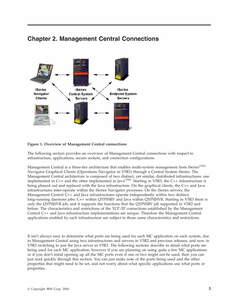
Figure
1.
Overview
of
Management
Central
connections
The
following
section
provides
an
overview
of
Management
Central
connections
with
respect
to
infrastructure,
applications,
secure
sockets,
and
connection
configurations.
Management
Central
is
a
three-tier
architecture
that
enables
multi-system
management
from
iSeries(TM)
Navigator
Graphical
Clients
(Operations
Navigator
in
V5R1)
through
a
Central
System
iSeries.
The
Management
Central
architecture
is
composed
of
two
distinct,
yet
similar,
distributed
infrastructures:
one
implemented
in
C++
and
the
other
implemented
in
Java(TM).
Starting
in
V5R3,
the
C++
infrastructure
is
being
phased
out
and
replaced
with
the
Java
infrastructure.
On
the
graphical
clients,
the
C++
and
Java
infrastructures
inter-operate
within
the
iSeries
Navigator
processes.
On
the
iSeries
servers,
the
Management
Central
C++
and
Java
infrastructures
operate
independently
within
two
distinct,
long-running
daemons
jobs:
C++
within
QYPSSRV
and
Java
within
QYPSJSVR.
Starting
in
V5R3
there
is
only
the
QYPSJSVR
job,
and
it
supports
the
functions
that
the
QYPSSRV
job
supported
in
V5R2
and
before.
The
characteristics
and
restrictions
of
the
TCP/IP
connections
established
by
the
Management
Central
C++
and
Java
infrastructure
implementations
are
unique.
Therefore
the
Management
Central
applications
enabled
by
each
infrastructure
are
subject
to
those
same
characteristics
and
restrictions.
It
isn’t
always
easy
to
determine
what
ports
are
being
used
for
each
MC
application
on
each
system,
due
to
Management
Central
using
two
infrastructures
and
servers
in
V5R2
and
previous
releases,
and
now
in
V5R3
switching
to
just
the
Java
server
in
V5R3.
The
following
sections
describe
in
detail
what
ports
are
being
used
for
each
MC
application,
however
if
you
are
planning
on
using
quite
a
few
MC
applications
or
if
you
don’t
mind
opening
up
all
the
MC
ports
even
if
one
or
two
might
not
be
used,
then
you
can
just
read
quickly
through
this
section.
You
can
just
make
note
of
the
ports
being
used
and
the
other
properties
that
might
need
to
be
set,
and
not
worry
about
what
specific
applications
use
what
ports
or
properties.
©
Copyright
IBM
Corp.
2004
3
C++
Infrastructure
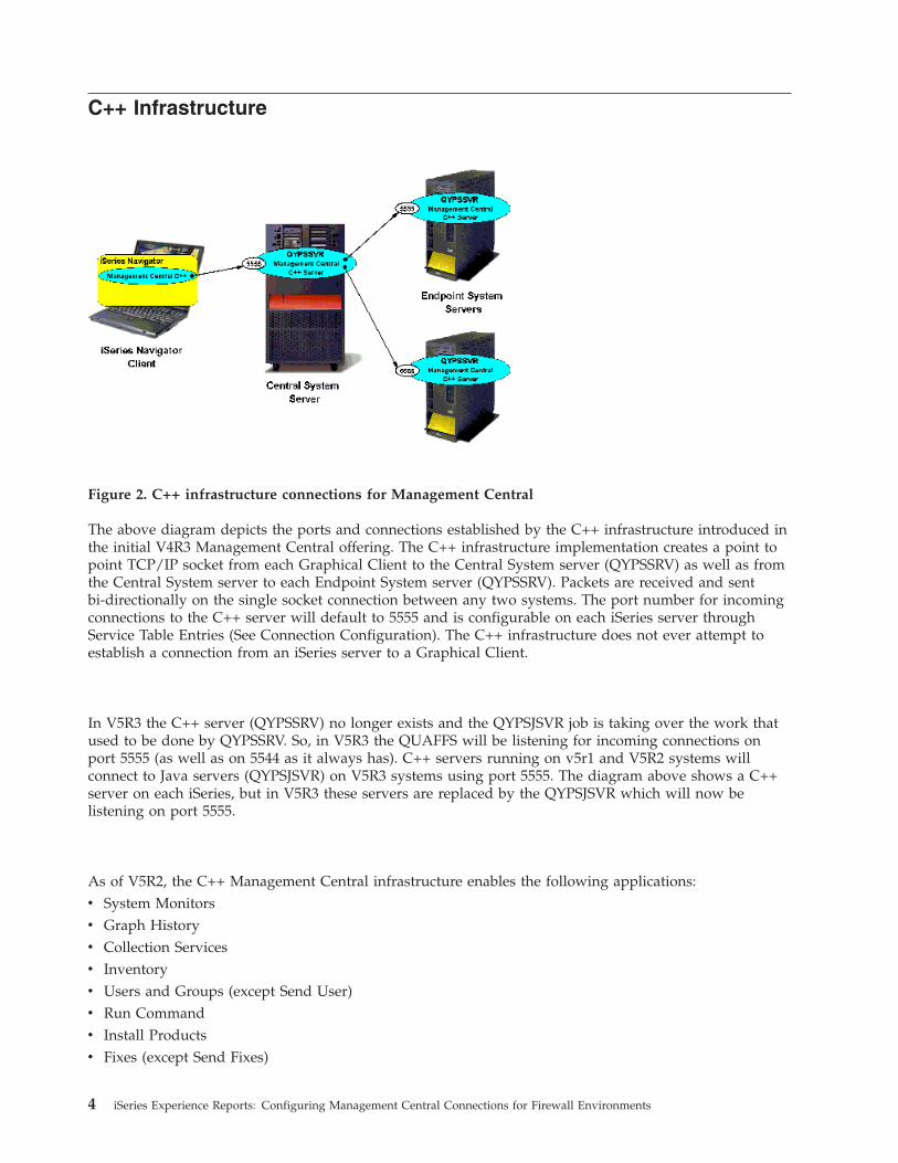
Figure
2.
C++
infrastructure
connections
for
Management
Central
The
above
diagram
depicts
the
ports
and
connections
established
by
the
C++
infrastructure
introduced
in
the
initial
V4R3
Management
Central
offering.
The
C++
infrastructure
implementation
creates
a
point
to
point
TCP/IP
socket
from
each
Graphical
Client
to
the
Central
System
server
(QYPSSRV)
as
well
as
from
the
Central
System
server
to
each
Endpoint
System
server
(QYPSSRV).
Packets
are
received
and
sent
bi-directionally
on
the
single
socket
connection
between
any
two
systems.
The
port
number
for
incoming
connections
to
the
C++
server
will
default
to
5555
and
is
configurable
on
each
iSeries
server
through
Service
Table
Entries
(See
Connection
Configuration).
The
C++
infrastructure
does
not
ever
attempt
to
establish
a
connection
from
an
iSeries
server
to
a
Graphical
Client.
In
V5R3
the
C++
server
(QYPSSRV)
no
longer
exists
and
the
QYPSJSVR
job
is
taking
over
the
work
that
used
to
be
done
by
QYPSSRV.
So,
in
V5R3
the
QUAFFS
will
be
listening
for
incoming
connections
on
port
5555
(as
well
as
on
5544
as
it
always
has).
C++
servers
running
on
v5r1
and
V5R2
systems
will
connect
to
Java
servers
(QYPSJSVR)
on
V5R3
systems
using
port
5555.
The
diagram
above
shows
a
C++
server
on
each
iSeries,
but
in
V5R3
these
servers
are
replaced
by
the
QYPSJSVR
which
will
now
be
listening
on
port
5555.
As
of
V5R2,
the
C++
Management
Central
infrastructure
enables
the
following
applications:
v
System
Monitors
v
Graph
History
v
Collection
Services
v
Inventory
v
Users
and
Groups
(except
Send
User)
v
Run
Command
v
Install
Products
v
Fixes
(except
Send
Fixes)
4
iSeries
Experience
Reports:
Configuring
Management
Central
Connections
for
Firewall
Environments
On
V5R3
systems,
these
applications
are
being
run
using
the
Management
Central
Java
infrastructure
(which
is
described
in
a
later
section).
So,
when
these
applications
run
between
V5R3
systems
they
will
communicate
using
the
Java
infrastructure
port,
and
when
these
applications
run
between
V5R2
systems
(or
between
a
V5R2
system
and
a
V5R3
system)
they
will
use
the
CA++
Infrastructure
port.
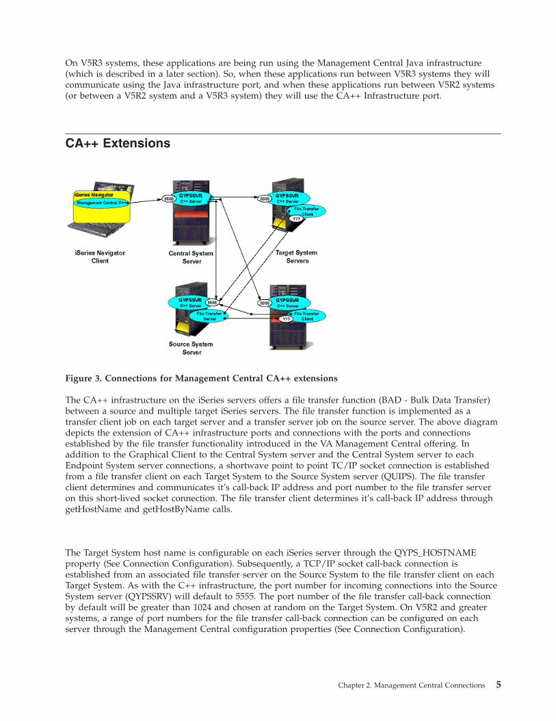
CA++
Extensions
Figure
3.
Connections
for
Management
Central
CA++
extensions
The
CA++
infrastructure
on
the
iSeries
servers
offers
a
file
transfer
function
(BAD
-
Bulk
Data
Transfer)
between
a
source
and
multiple
target
iSeries
servers.
The
file
transfer
function
is
implemented
as
a
transfer
client
job
on
each
target
server
and
a
transfer
server
job
on
the
source
server.
The
above
diagram
depicts
the
extension
of
CA++
infrastructure
ports
and
connections
with
the
ports
and
connections
established
by
the
file
transfer
functionality
introduced
in
the
VA
Management
Central
offering.
In
addition
to
the
Graphical
Client
to
the
Central
System
server
and
the
Central
System
server
to
each
Endpoint
System
server
connections,
a
shortwave
point
to
point
TC/IP
socket
connection
is
established
from
a
file
transfer
client
on
each
Target
System
to
the
Source
System
server
(QUIPS).
The
file
transfer
client
determines
and
communicates
it’s
call-back
IP
address
and
port
number
to
the
file
transfer
server
on
this
short-lived
socket
connection.
The
file
transfer
client
determines
it’s
call-back
IP
address
through
getHostName
and
getHostByName
calls.
The
Target
System
host
name
is
configurable
on
each
iSeries
server
through
the
QYPS_HOSTNAME
property
(See
Connection
Configuration).
Subsequently,
a
TCP/IP
socket
call-back
connection
is
established
from
an
associated
file
transfer
server
on
the
Source
System
to
the
file
transfer
client
on
each
Target
System.
As
with
the
C++
infrastructure,
the
port
number
for
incoming
connections
into
the
Source
System
server
(QYPSSRV)
will
default
to
5555.
The
port
number
of
the
file
transfer
call-back
connection
by
default
will
be
greater
than
1024
and
chosen
at
random
on
the
Target
System.
On
V5R2
and
greater
systems,
a
range
of
port
numbers
for
the
file
transfer
call-back
connection
can
be
configured
on
each
server
through
the
Management
Central
configuration
properties
(See
Connection
Configuration).
Chapter
2.
Management
Central
Connections
5
As
of
V5R2,
the
following
Management
Central
applications
enabled
by
the
V5R2++
infrastructure
also
leverage
the
C++
file
transfer
functionality:
v
Package
Distribution
v
Send
Products
v
Send
User
v
Send
Fixes
As
mentioned
in
the
C++
Infrastructure
section
above,
in
V5R3
the
Java
server
is
taking
over
for
the
C++
server
and
the
QYPSSRV
job
doesn’t
exist.
So,
on
V5R3
systems
the
above
applications
are
being
run
using
the
Management
Central
Java
infrastructure
and
the
Management
Central
Java
extensions
(which
are
described
in
later
sections.
This
means
that
when
these
applications
run
between
V5R3
systems,
they
will
communicate
using
the
Java
infrastructure
and
Java
extension
ports,
and
when
these
applications
run
between
V5R2
systems
(or
between
a
V5R2
system
and
a
V5R3
system),
they
will
use
the
C++
Infrastructure
and
C++
extension
ports.
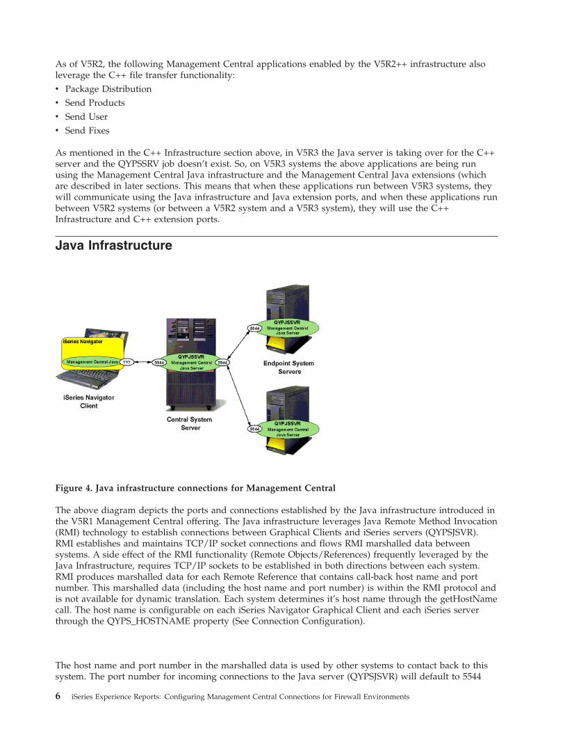
Java
Infrastructure
Figure
4.
Java
infrastructure
connections
for
Management
Central
The
above
diagram
depicts
the
ports
and
connections
established
by
the
Java
infrastructure
introduced
in
the
V5R1
Management
Central
offering.
The
Java
infrastructure
leverages
Java
Remote
Method
Invocation
(RMI)
technology
to
establish
connections
between
Graphical
Clients
and
iSeries
servers
(QYPSJSVR).
RMI
establishes
and
maintains
TCP/IP
socket
connections
and
flows
RMI
marshalled
data
between
systems.
A
side
effect
of
the
RMI
functionality
(Remote
Objects/References)
frequently
leveraged
by
the
Java
Infrastructure,
requires
TCP/IP
sockets
to
be
established
in
both
directions
between
each
system.
RMI
produces
marshalled
data
for
each
Remote
Reference
that
contains
call-back
host
name
and
port
number.
This
marshalled
data
(including
the
host
name
and
port
number)
is
within
the
RMI
protocol
and
is
not
available
for
dynamic
translation.
Each
system
determines
it’s
host
name
through
the
getHostName
call.
The
host
name
is
configurable
on
each
iSeries
Navigator
Graphical
Client
and
each
iSeries
server
through
the
QYPS_HOSTNAME
property
(See
Connection
Configuration).
The
host
name
and
port
number
in
the
marshalled
data
is
used
by
other
systems
to
contact
back
to
this
system.
The
port
number
for
incoming
connections
to
the
Java
server
(QYPSJSVR)
will
default
to
5544
6
iSeries
Experience
Reports:
Configuring
Management
Central
Connections
for
Firewall
Environments
and
is
configurable
on
each
iSeries
server
through
Service
Table
Entries
(See
Connection
Configuration).
The
port
number
for
incoming
Java
infrastructure
connections
to
the
Graphical
Client
by
default
will
be
chosen
at
random
on
the
client
system
and
is
configurable
on
each
client
through
a
properties
file
(See
Connection
Configuration).
The
host
name
in
the
marshalled
data
(which
can
be
either
an
actual
host
name
or
an
IP
address)
represents
the
address
that
other
systems
will
use
to
contact
this
system.
This
host
name
will
default
to
the
IP
address
that
the
host
recognizes
as
its
own
and
is
configurable
on
each
iSeries
server
and
Graphical
Client
through
the
QYPS_HOSTNAME
property
(See
Connection
Configuration).
The
Java
infrastructure
was
introduced
in
the
V5R1
Management
Central
offering
and
as
of
V5R3
enables
the
following
applications:
v
System
Values
Compare
and
Update
v
Synchronize
Date
and
Time
v
Synchronize
Functions
v
Job
Monitor
v
Message
Monitor
v
File
Monitor
v
B2B
Monitors
v
BRMS
tasks
v
Schedule
LPAR
resource
moves
The
following
applications
use
the
Java
infrastructure
on
V5R3
systems,
but
use
the
C++
infrastructure
on
V5R2
and
earlier
systems
(see
the
C++
infrastructure
section
for
details):
v
System
Monitors
v
Graph
History
v
Collection
Services
v
Inventory
v
Users
and
Groups
(except
Send
User)
v
Run
Command
v
Install
Products
v
Fixes
(except
Send
Fixes)
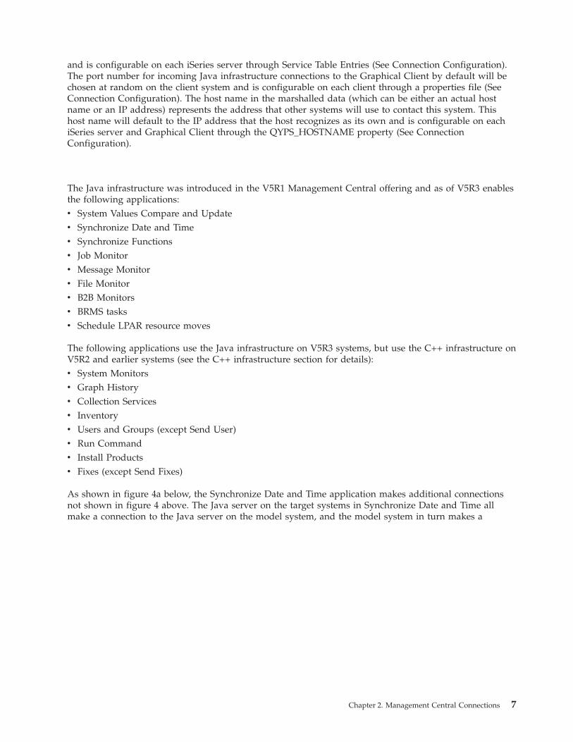
As
shown
in
figure
4a
below,
the
Synchronize
Date
and
Time
application
makes
additional
connections
not
shown
in
figure
4
above.
The
Java
server
on
the
target
systems
in
Synchronize
Date
and
Time
all
make
a
connection
to
the
Java
server
on
the
model
system,
and
the
model
system
in
turn
makes
a
Chapter
2.
Management
Central
Connections
7
connection
back
to
the
Java
server
on
each
target
system.
Figure
4a.
Synchronize
date
and
time
connections
for
Management
Central
Also,
the
Synchronize
Functions
application
treats
its
model
system
just
like
another
endpoint,
meaning
that
the
Java
server
on
the
CS
contacts
the
Java
server
on
the
model
system,
and
the
Java
server
on
the
model
system
contacts
the
Java
server
on
the
CS.
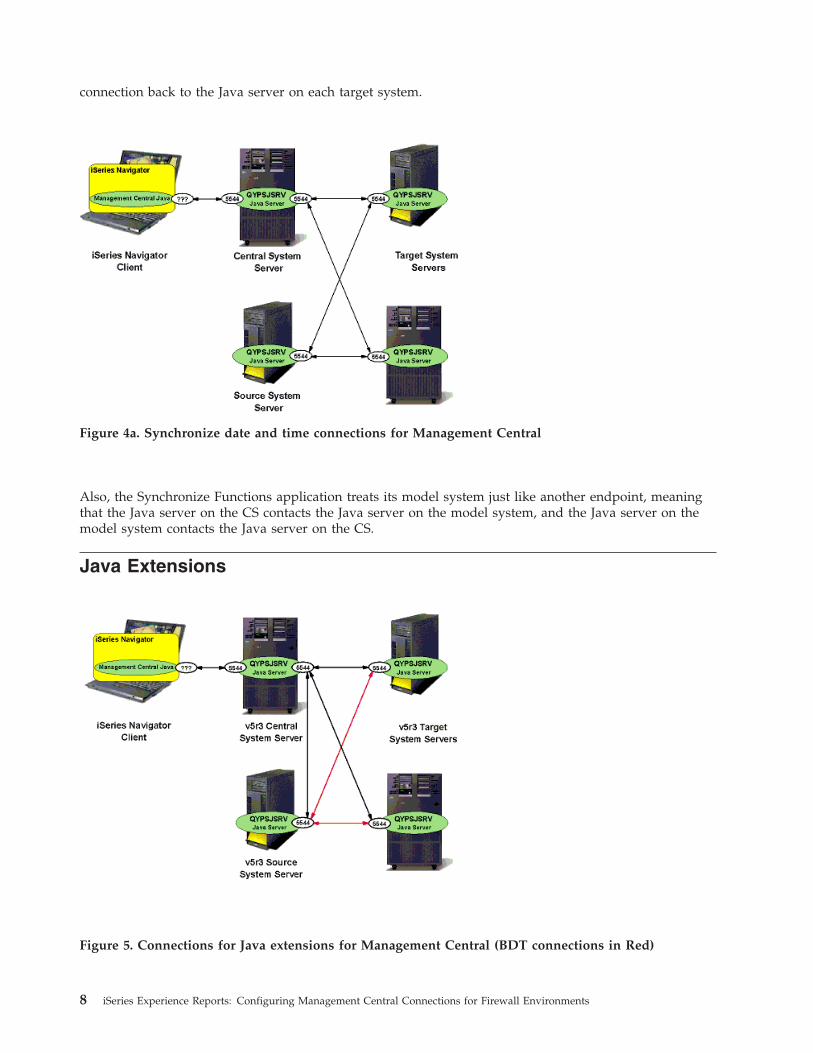
Java
Extensions
Figure
5.
Connections
for
Java
extensions
for
Management
Central
(BDT
connections
in
Red)
8
iSeries
Experience
Reports:
Configuring
Management
Central
Connections
for
Firewall
Environments
The
Java
infrastructure
in
V5R3
added
a
file
transfer
function
(BDT
-
Bulk
Data
Transfer)
between
a
source
and
multiple
target
iSeries
servers.
This
BDT
function
serves
the
same
purpose
as
the
BDT
function
in
C++
(see
the
C++
Extensions
section
above),
however
it
is
implemented
in
a
different
way.
The
Java
file
transfer
function
uses
the
Java
infrastructure
port
in
order
to
accomplish
the
file
transfer,
but
is
only
available
between
V5R3
and
higher
source
systems
and
V5R3
and
higher
target
systems,
since
this
feature
is
new
in
V5R3.
To
accomplish
file
transfer
between
a
source
and
a
target
system
where
one
(or
both)
of
the
systems
is
at
V5R2
or
earlier,
the
C++
file
transfer
function
and
its
associated
ports
are
used.
Figure
5
above
shows
the
connections
used
for
Java
BDT
between
a
V5R3
source
system
and
V5R3
target
systems.
Note
that
when
using
a
V5R3
source
and
a
V5R3
target
system,
the
Bulk
Data
Transfer
uses
connections
initiated
on
port
5544
which
means
the
range
of
port
numbers
mentioned
in
the
C++
Extensions
section
above
isn’t
being
used.
If
either
the
source
or
the
target
is
an
earlier
release
than
V5R3
however,
this
range
of
ports
is
used
(since
the
C++
Extensions
ports
are
being
used).
As
of
V5R3,
the
following
Management
Central
applications
now
use
the
Java
infrastructure
and
also
leverage
the
Java
file
transfer
functionality.
v
Package
Distribution
v
Send
Products
v
Send
User
v
Send
Fixes
Note
that
these
applications
use
the
Java
file
transfer
functionality
when
only
V5R3
and
higher
systems
are
involved.
Communications
that
include
at
least
one
V5R2
or
earlier
system
still
use
the
C++
file
transfer
functionality
(see
the
C++
extensions
section
for
details).
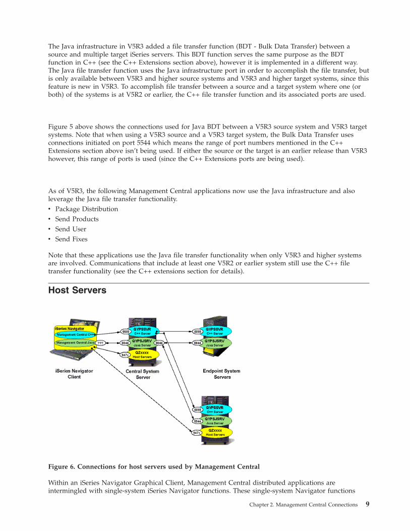
Host
Servers
Figure
6.
Connections
for
host
servers
used
by
Management
Central
Within
an
iSeries
Navigator
Graphical
Client,
Management
Central
distributed
applications
are
intermingled
with
single-system
iSeries
Navigator
functions.
These
single-system
Navigator
functions
Chapter
2.
Management
Central
Connections
9
establish
point
to
point
TCP/IP
socket
connections
to
a
set
of
iSeries
Host
Servers.
The
point
to
point
socket
connections
to
these
iSeries
Host
Servers
are
shared
between
applications
within
each
iSeries
Navigator
client.
Several
Management
Central
application
implementations
leverage
these
shared
Host
Server
connections
on
the
Graphical
Client
to
interact
with
the
Central
System.
A
few
Management
Central
applications
leverage
these
connections
to
interact
directly
with
Endpoint
Systems
as
well.
For
example,
System
Values
Compare
and
Update
contacts
the
Model
System
directly
from
iSeries
Navigator
Graphical
Client
to
retrieve
System
Values
from
the
model
system.
The
Information
urls:
http://publib.boulder.ibm.com/iseries/V5R3/ic2924/index.htm?info/rzaii/rzaiihstsvrbyfnctn.htm
and
http://publib.boulder.ibm.com/iseries/V5R3/ic2924/index.htm?info/rzaii/rzaiicahstsvr.htm
document
the
iSeries
Host
Servers
and
the
functions
they
provide
to
client
applications.
To
get
a
list
of
the
port
numbers
used
by
each
iSeries
Host
Server,
go
to
url:
http://www-1.ibm.com/servers/eserver/iseries/access/caiixe1.htm
and
select
APAR
II12227.
The
port
numbers
utilized
by
the
iSeries
Host
Servers
typically
leveraged
by
Management
Central
range
from
8470
to
8476
for
non-SSL
connections
and
9470
to
9476
for
SSL
connections.
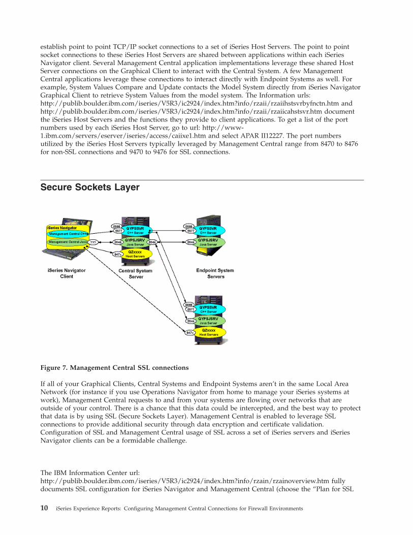
Secure
Sockets
Layer
Figure
7.
Management
Central
SSL
connections
If
all
of
your
Graphical
Clients,
Central
Systems
and
Endpoint
Systems
aren’t
in
the
same
Local
Area
Network
(for
instance
if
you
use
Operations
Navigator
from
home
to
manage
your
iSeries
systems
at
work),
Management
Central
requests
to
and
from
your
systems
are
flowing
over
networks
that
are
outside
of
your
control.
There
is
a
chance
that
this
data
could
be
intercepted,
and
the
best
way
to
protect
that
data
is
by
using
SSL
(Secure
Sockets
Layer).
Management
Central
is
enabled
to
leverage
SSL
connections
to
provide
additional
security
through
data
encryption
and
certificate
validation.
Configuration
of
SSL
and
Management
Central
usage
of
SSL
across
a
set
of
iSeries
servers
and
iSeries
Navigator
clients
can
be
a
formidable
challenge.
The
IBM
Information
Center
url:
http://publib.boulder.ibm.com/iseries/V5R3/ic2924/index.htm?info/rzain/rzainoverview.htm
fully
documents
SSL
configuration
for
iSeries
Navigator
and
Management
Central
(choose
the
“Plan
for
SSL
10
iSeries
Experience
Reports:
Configuring
Management
Central
Connections
for
Firewall
Environments
enablement”,
and
then
the
“Secure
applications
with
SSL
->
Management
Central”
links).
Once
Management
Central
is
configured
for
SSL
and
SSL
is
enabled,
Server
Authentication
within
the
C++
infrastructure
will
utilize
port
number
5566
and
Client/Server
Authentication
within
the
C++
infrastructure
will
use
port
number
5577.
When
SSL
is
enabled
the
only
impact
to
Management
Central
connections
and
port
numbers
in
that
the
5555
port
number
in
the
above
C++
infrastructure
connection
diagrams
would
be
replaced
with
5566
and/or
5577
depending
on
selected
authentication.
The
Java
infrastructure
continues
to
use
port
number
5544
regardless
of
SSL
enablement
or
selected
authentication.
Each
of
these
port
numbers
configurable
through
the
Management
Central
configuration
properties
(See
Connection
Configuration).
When
the
iSeries
Host
Servers
typically
leveraged
by
Management
Central
applications
are
configured
for
SSL,
the
port
numbers
utilized
by
those
Host
Servers
range
from
9470
to
9476.
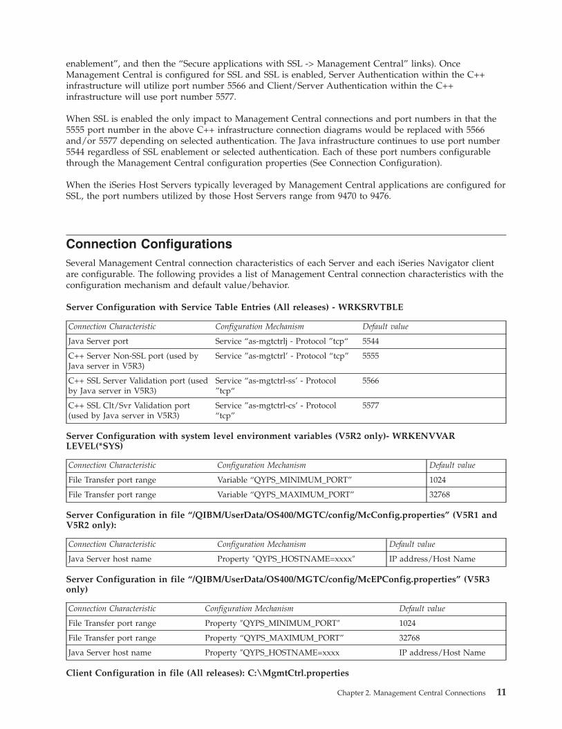
Connection
Configurations
Several
Management
Central
connection
characteristics
of
each
Server
and
each
iSeries
Navigator
client
are
configurable.
The
following
provides
a
list
of
Management
Central
connection
characteristics
with
the
configuration
mechanism
and
default
value/behavior.
Server
Configuration
with
Service
Table
Entries
(All
releases)
-
WRKSRVTBLE
Connection
Characteristic
Configuration
Mechanism
Default
value
Java
Server
port
Service
“as-mgtctrlj
-
Protocol
”tcp“
5544
C++
Server
Non-SSL
port
(used
by
Java
server
in
V5R3)
Service
”as-mgtctrl’
-
Protocol
“tcp”
5555
C++
SSL
Server
Validation
port
(used
by
Java
server
in
V5R3)
Service
“as-mgtctrl-ss’
-
Protocol
”tcp“
5566
C++
SSL
Clt/Svr
Validation
port
(used
by
Java
server
in
V5R3)
Service
”as-mgtctrl-cs’
-
Protocol
“tcp”
5577
Server
Configuration
with
system
level
environment
variables
(V5R2
only)-
WRKENVVAR
LEVEL(*SYS)
Connection
Characteristic
Configuration
Mechanism
Default
value
File
Transfer
port
range
Variable
“QYPS_MINIMUM_PORT”
1024
File
Transfer
port
range
Variable
“QYPS_MAXIMUM_PORT”
32768
Server
Configuration
in
file
“/QIBM/UserData/OS400/MGTC/config/McConfig.properties”
(V5R1
and
V5R2
only):
Connection
Characteristic
Configuration
Mechanism
Default
value
Java
Server
host
name
Property
″QYPS_HOSTNAME=xxxx″
IP
address/Host
Name
Server
Configuration
in
file
“/QIBM/UserData/OS400/MGTC/config/McEPConfig.properties”
(V5R3
only)
Connection
Characteristic
Configuration
Mechanism
Default
value
File
Transfer
port
range
Property
″QYPS_MINIMUM_PORT″
1024
File
Transfer
port
range
Property
“QYPS_MAXIMUM_PORT”
32768
Java
Server
host
name
Property
″QYPS_HOSTNAME=xxxx
IP
address/Host
Name
Client
Configuration
in
file
(All
releases):
C:\MgmtCtrl.properties
Chapter
2.
Management
Central
Connections
11
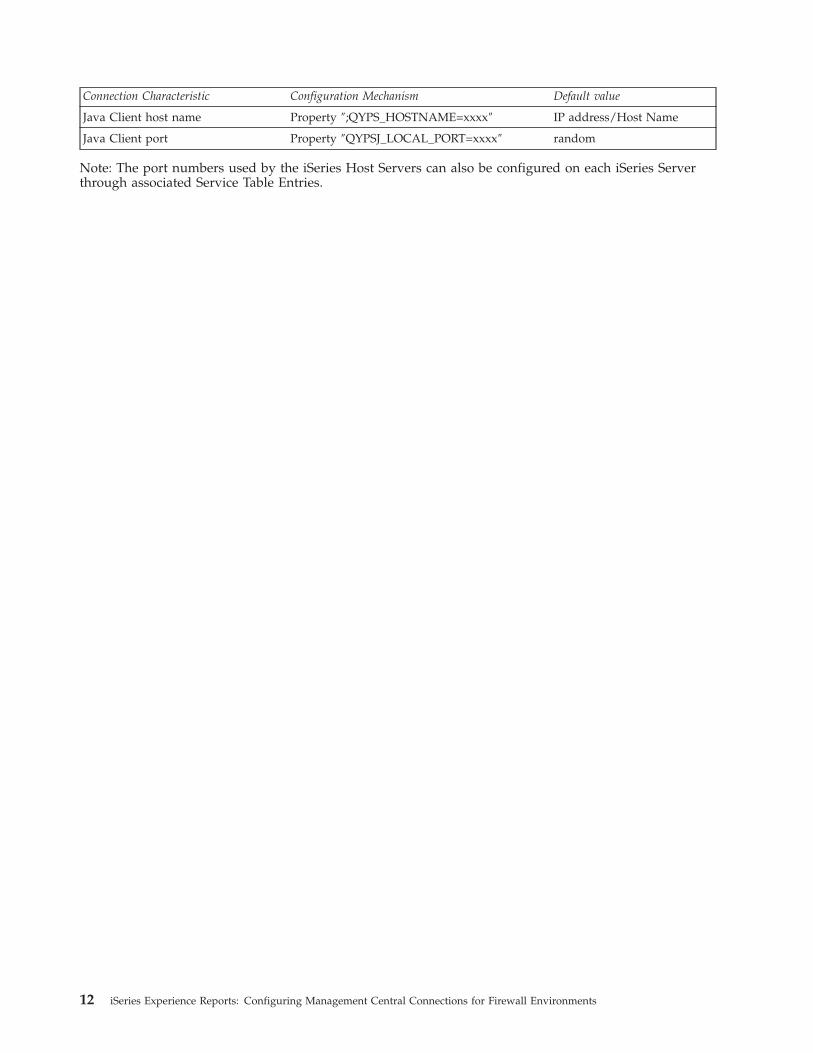
Connection
Characteristic
Configuration
Mechanism
Default
value
Java
Client
host
name
Property
″;QYPS_HOSTNAME=xxxx″
IP
address/Host
Name
Java
Client
port
Property
″QYPSJ_LOCAL_PORT=xxxx″
random
Note:
The
port
numbers
used
by
the
iSeries
Host
Servers
can
also
be
configured
on
each
iSeries
Server
through
associated
Service
Table
Entries.
12
iSeries
Experience
Reports:
Configuring
Management
Central
Connections
for
Firewall
Environments
Chapter
3.
Management
Central
Firewall
Quick
Reference
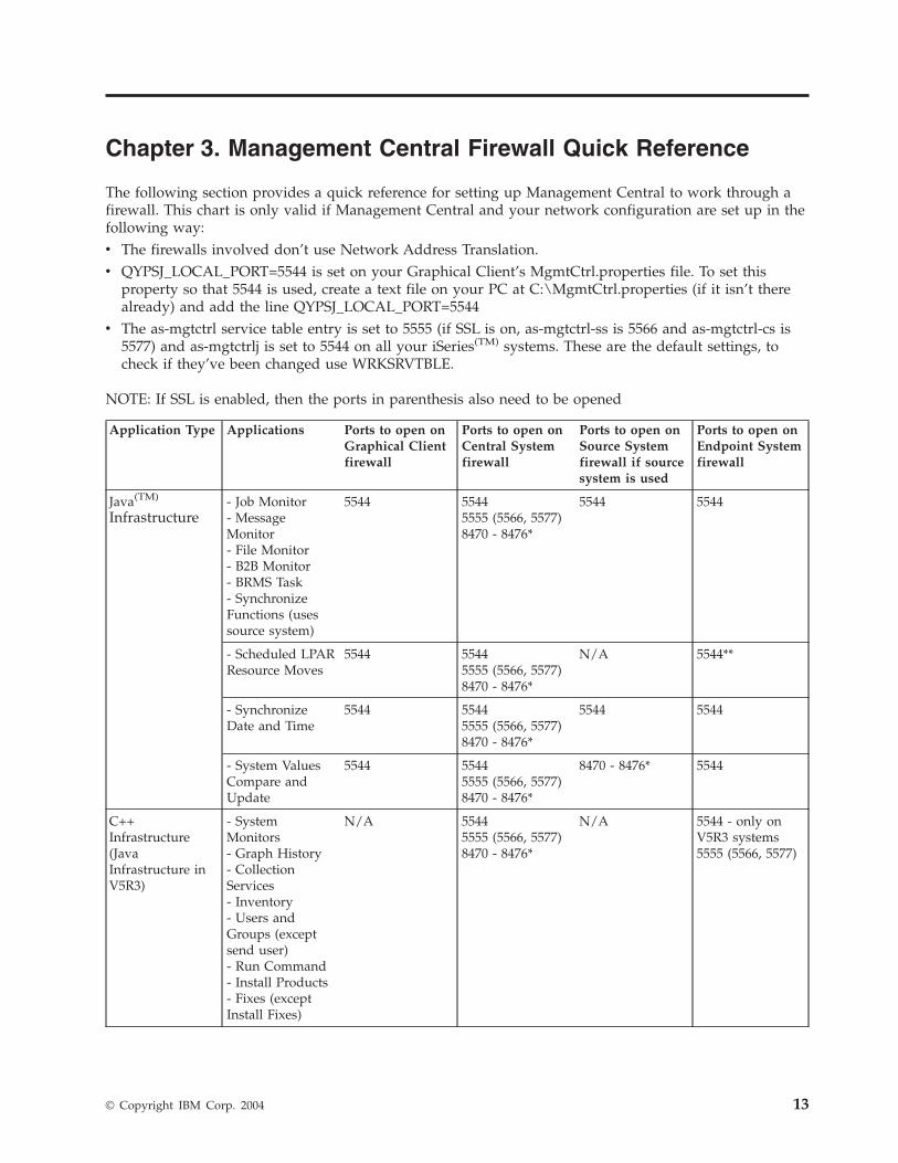
The
following
section
provides
a
quick
reference
for
setting
up
Management
Central
to
work
through
a
firewall.
This
chart
is
only
valid
if
Management
Central
and
your
network
configuration
are
set
up
in
the
following
way:
v
The
firewalls
involved
don’t
use
Network
Address
Translation.
v
QYPSJ_LOCAL_PORT=5544
is
set
on
your
Graphical
Client’s
MgmtCtrl.properties
file.
To
set
this
property
so
that
5544
is
used,
create
a
text
file
on
your
PC
at
C:\MgmtCtrl.properties
(if
it
isn’t
there
already)
and
add
the
line
QYPSJ_LOCAL_PORT=5544
v
The
as-mgtctrl
service
table
entry
is
set
to
5555
(if
SSL
is
on,
as-mgtctrl-ss
is
5566
and
as-mgtctrl-cs
is
5577)
and
as-mgtctrlj
is
set
to
5544
on
all
your
iSeries(TM)
systems.
These
are
the
default
settings,
to
check
if
they’ve
been
changed
use
WRKSRVTBLE.
NOTE:
If
SSL
is
enabled,
then
the
ports
in
parenthesis
also
need
to
be
opened
Application
Type
Applications
Ports
to
open
on
Graphical
Client
firewall
Ports
to
open
on
Central
System
firewall
Ports
to
open
on
Source
System
firewall
if
source
system
is
used
Ports
to
open
on
Endpoint
System
firewall
Java(TM)
Infrastructure
-
Job
Monitor-
Message
Monitor-
File
Monitor-
B2B
Monitor-
BRMS
Task-
Synchronize
Functions
(uses
source
system)
5544
55445555
(5566,
5577)8470
-
8476*
5544
5544
-
Scheduled
LPAR
Resource
Moves
5544
55445555
(5566,
5577)8470
-
8476*
N/A
5544**
-
Synchronize
Date
and
Time
5544
55445555
(5566,
5577)8470
-
8476*
5544
5544
-
System
Values
Compare
and
Update
5544
55445555
(5566,
5577)8470
-
8476*
8470
-
8476*
5544
C++
Infrastructure
(Java
Infrastructure
in
V5R3)
-
System
Monitors-
Graph
History-
Collection
Services-
Inventory-
Users
and
Groups
(except
send
user)-
Run
Command-
Install
Products-
Fixes
(except
Install
Fixes)
N/A
55445555
(5566,
5577)8470
-
8476*
N/A
5544
-
only
on
V5R3
systems5555
(5566,
5577)
©
Copyright
IBM
Corp.
2004
13
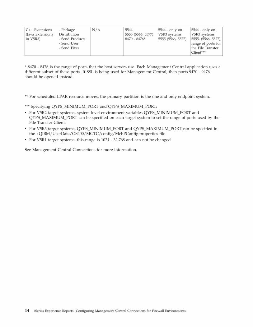
C++
Extensions
(Java
Extensions
in
V5R3)
-
Package
Distribution-
Send
Products-
Send
User-
Send
Fixes
N/A
55445555
(5566,
5577)8470
-
8476*
5544
-
only
on
V5R3
systems
5555
(5566,
5577)
5544
-
only
on
V5R3
systems5555,
(5566,
5577),
range
of
ports
for
the
File
Transfer
Client***
*
8470
-
8476
is
the
range
of
ports
that
the
host
servers
use.
Each
Management
Central
application
uses
a
different
subset
of
these
ports.
If
SSL
is
being
used
for
Management
Central,
then
ports
9470
-
9476
should
be
opened
instead.
**
For
scheduled
LPAR
resource
moves,
the
primary
partition
is
the
one
and
only
endpoint
system.
***
Specifying
QYPS_MINIMUM_PORT
and
QYPS_MAXIMUM_PORT:
v
For
V5R2
target
systems,
system
level
environment
variables
QYPS_MINIMUM_PORT
and
QYPS_MAXIMUM_PORT
can
be
specified
on
each
target
system
to
set
the
range
of
ports
used
by
the
File
Transfer
Client.
v
For
V5R3
target
systems,
QYPS_MINIMUM_PORT
and
QYPS_MAXIMUM_PORT
can
be
specified
in
the
/QIBM/UserData/OS400/MGTC/config/McEPConfig.properties
file
v
For
V5R1
target
systems,
this
range
is
1024
-
32,768
and
can
not
be
changed.
See
Management
Central
Connections
for
more
information.
14
iSeries
Experience
Reports:
Configuring
Management
Central
Connections
for
Firewall
Environments
Chapter
4.
Management
Central
Limitations
due
to
Network
Address
Translation
Firewalls,
by
definition,
restrict
the
types
of
connections
that
can
be
made
to
a
given
system
or
set
of
systems.
Sometimes
in
order
for
distributed
applications
to
work,
the
firewall
configuration
and/or
the
application
configuration
need
to
be
altered.
Sometimes
there
are
no
configuration
changes
that
will
allow
that
application
to
work
(short
of
disabling
or
removing
the
firewall
completely).
This
section
discusses
firewalls
that
use
Network
Address
Translation
and
the
restrictions
they
can
cause
on
distributed
applications
such
as
Management
Central.
Network
Address
Translation
(NAT)
Many
firewalls
can
be
configured
use
Network
Address
Translation
(NAT).
To
do
this
an
administrator
sets
up
rules
where
some
or
all
of
the
requests
that
come
in
to
and
go
out
from
the
protected
systems
are
altered
by
changing
the
IP
address
they
are
going
to
or
coming
from.
There
are
many
types
of
Network
Address
Translation,
but
there
are
two
main
categories:
Dynamic
NAT
and
Static
NAT.
As
a
general
rule
(with
a
few
exceptions),
most
of
Management
Central
can
be
configured
to
work
with
Static
NAT,
but
can
not
be
configured
to
work
with
Dynamic
NAT.
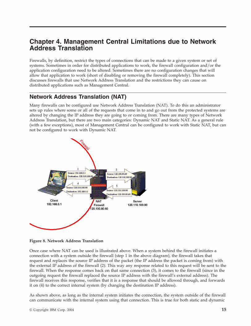
Figure
8.
Network
Address
Translation
Once
case
where
NAT
can
be
used
is
illustrated
above.
When
a
system
behind
the
firewall
initiates
a
connection
with
a
system
outside
the
firewall
(step
1
in
the
above
diagram),
the
firewall
takes
that
request
and
replaces
the
source
IP
address
of
the
packet
(the
IP
address
the
packet
is
coming
from)
with
the
external
IP
address
of
the
firewall
(2).
This
way
any
response
related
to
this
request
will
be
sent
to
the
firewall.
When
the
response
comes
back
on
that
same
connection
(3),
it
comes
to
the
firewall
(since
in
the
outgoing
request
the
firewall
replaced
the
source
IP
address
with
the
firewall’s
external
address).
The
firewall
receives
this
response,
verifies
that
it
is
a
response
that
should
be
allowed
through,
and
forwards
it
on
(4)
to
the
correct
internal
system
(by
changing
the
destination
IP
address).
As
shown
above,
as
long
as
the
internal
system
initiates
the
connection,
the
system
outside
of
the
firewall
can
communicate
with
the
internal
system
using
that
connection.
This
is
true
for
both
static
and
dynamic
©
Copyright
IBM
Corp.
2004
15
NAT.
The
difference
between
static
and
dynamic
NAT
is
that
static
NAT
makes
it
possible
for
external
systems
to
initiate
connections
with
systems
inside
the
firewall
but
dynamic
NAT
does
not.
Static
NAT
With
static
NAT,
there
is
a
table
that
maps
internal
IP
addresses
to
external
IP
addresses.
If
a
request
was
being
sent
from
a
system
inside
the
firewall
with
internal
IP
address
192.168.0.1,
the
firewall
would
look
up
that
internal
address
in
the
table
to
find
out
what
external
address
should
be
used
to
replace
it.
Then,
when
a
response
comes
back
to
that
external
IP
address,
the
firewall
uses
that
table
again
to
see
what
internal
system
is
associated
with
that
external
IP.
This
table
is
static
(meaning
an
internal
system’s
external
IP
address
will
always
be
the
same).
This
means
that
systems
outside
the
firewall
are
able
to
initiate
a
connection
to
that
internal
system
as
long
as
that
external
system
knew
the
internal
system’s
external
IP
address.
Dynamic
NAT
With
dynamic
NAT,
the
firewall
dynamically
determines
what
external
IP
address
to
give
to
an
outgoing
request.
It
could
be
that
all
requests
get
the
same
external
IP
address,
or
they
could
each
get
the
next
available
one
in
a
pool
of
external
IP
addresses.
Since
there
isn’t
a
static
table,
at
one
point
the
internal
system
could
have
an
external
address
of
120.110.100.95
and
the
next
time
could
have
an
external
address
of
120.110.90.85.
Each
time
the
firewall
replaces
an
internal
IP
address
with
an
external
address,
it
makes
a
record
of
this
so
that
when
a
response
comes
back
on
the
same
connection,
the
firewall
will
be
able
to
route
that
response
to
the
correct
internal
IP
address.
This
way
of
distributing
external
IP
addresses
results
in
systems
outside
the
firewall
not
being
able
to
initiate
a
connection
to
an
internal
system,
(since
there
is
no
way
for
an
external
system
to
determine
what
external
IP
address
to
use).
The
only
way
a
system
outside
the
firewall
can
talk
to
a
system
inside
the
firewall
is
to
respond
to
a
request
that
was
initiated
by
the
system
inside
the
firewall.
Management
Central
Limitations
Any
distributed
applications
(including
Management
Central
applications)
that
need
to
initiate
a
connection
from
an
external
system
to
a
system
inside
a
firewall
won’t
work
with
dynamic
NAT.
For
information
about
using
Management
Central
with
a
specific
Dynamic
NAT
setup
refer
to
the
previous
Management
Central
Connections
section
to
determine
what
Management
Central
applications
use
what
connections
(PC
to
CS,
CS
to
PC,
CS
to
EP,
EP
to
CS,
etc).
Use
that
information
along
with
information
about
what
systems
and
connections
are
using
Dynamic
NAT
to
figure
out
what
applications
will
and
won’t
work..
Distributed
applications
(including
Management
Central
applications)
that
need
to
establish
a
connection
from
an
external
system
to
a
system
behind
a
firewall
should
work
with
Static
NAT.
However,
many
times
these
applications
have
to
be
specially
configured
so
that
the
external
system
trying
to
establish
a
connection
with
the
system
behind
the
firewall
uses
that
internal
system’s
external
IP
address.
For
Management
Central,
if
a
system
(iSeries(TM)
or
PC)
is
inside
a
firewall
that
is
using
Static
NAT,
that
system
needs
to
set
its
own
QYPS_HOSTNAME
property
to
its
external
IP
address.
Or,
if
that
system
will
have
systems
both
inside
and
outside
the
firewall
connecting
to
it,
it
needs
to
set
its
own
QYPS_HOSTNAME
to
a
hostname
that
will
resolve
to
its
internal
IP
address
on
internal
systems,
and
to
its
external
IP
address
on
external
systems.
The
Management
Central
Connections
section
describes
how
to
set
this
QYPS_HOSTNAME
property
(setting
this
property
is
different
depending
on
what
release
your
system
is
at).
16
iSeries
Experience
Reports:
Configuring
Management
Central
Connections
for
Firewall
Environments
Chapter
5.
Graphical
Client
Protected
by
a
Firewall
Management
Central
Graphical
clients
that
are
also
used
to
connect
directly
to
the
Internet
are
often
protected
by
a
firewall.
Software
and/or
hardware
firewalls
are
becoming
common
in
homes
with
high
speed
internet
access.
Without
special
configuration
this
simple
firewall
environment
can
restrict
Management
Central
functionality.
Objectives
Detail
Management
Central
configuration
required
within
a
common
firewall
environment
where
the
Graphical
Client
is
protected
by
a
firewall.
Details
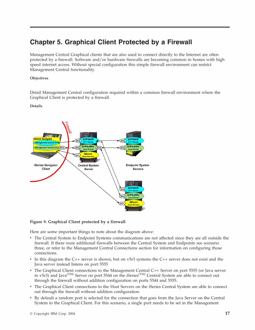
Figure
9.
Graphical
Client
protected
by
a
firewall
Here
are
some
important
things
to
note
about
the
diagram
above:
v
The
Central
System
to
Endpoint
Systems
communications
are
not
affected
since
they
are
all
outside
the
firewall.
If
there
were
additional
firewalls
between
the
Central
System
and
Endpoints
see
scenario
three,
or
refer
to
the
Management
Central
Connections
section
for
information
on
configuring
those
connections.
v
In
this
diagram
the
C++
server
is
shown,
but
on
v5r3
systems
the
C++
server
does
not
exist
and
the
Java
server
instead
listens
on
port
5555
v
The
Graphical
Client
connections
to
the
Management
Central
C++
Server
on
port
5555
(or
Java
server
in
v5r3)
and
Java(TM)
Server
on
port
5544
on
the
iSeries(TM)
Central
System
are
able
to
connect
out
through
the
firewall
without
addition
configuration
on
ports
5544
and
5555.
v
The
Graphical
Client
connections
to
the
Host
Servers
on
the
iSeries
Central
System
are
able
to
connect
out
through
the
firewall
without
addition
configuration.
v
By
default
a
random
port
is
selected
for
the
connection
that
goes
from
the
Java
Server
on
the
Central
System
to
the
Graphical
Client.
For
this
scenario,
a
single
port
needs
to
be
set
in
the
Management
©
Copyright
IBM
Corp.
2004
17
Central
PC’s
properties
file
(see
Connection
Configurations)
so
that
a
random
port
isn’t
used
to
connect
from
the
CS
back
to
the
Graphical
Client
(in
the
diagram
we’ve
picked
5544,
but
another
port
can
be
used).
See
the
instructions
below
for
more
information
about
this.
v
If
SSL
is
being
used,
ports
5566
and
5577
will
need
to
be
included
with
5555
throughout
this
document.
The
steps
to
configure
Management
Central
are
slightly
different
depending
on
how
the
firewall
is
configured
to
use
NAT.
Warning:
Temporary
Level
2
Header
Firewall
that
is
not
using
NAT
v
Set
the
port
used
to
connect
from
the
Central
System
to
the
Graphical
Client
to
a
specific
port
as
described
in
bullet
four
above
and
as
shown
in
the
diagram
(see
the
Management
Central
Connections
section
for
details).
v
Configure
the
firewall
to
open
the
specific
port
so
traffic
from
the
Central
System
can
get
to
the
Graphical
Client.
Firewall
that
uses
Static
NAT
v
Follow
the
instructions
(above)
for
a
firewall
that
is
not
using
NAT.
v
Set
the
QYPS_HOSTNAME
property
on
the
Graphical
Client
(see
the
Management
Central
Connections
section)
to
the
external
IP
address
of
this
Graphical
Client
(the
IP
address
used
by
systems
outside
of
the
firewall
to
contact
this
Graphical
Client).
Firewall
that
uses
Dynamic
NAT
If
the
firewall
protecting
the
Graphical
Client
is
using
Dynamic
NAT,
the
Central
System
won’t
be
able
to
contact
back
to
the
Graphical
Client.
This
will
prevent
all
MC
applications
that
use
the
Java
Infrastructure
from
working.
Applications
that
don’t
use
the
Java
Infrastructure
(including
applications
that
were
C++
applications
in
V5R2
and
were
converted
to
Java
applications
in
V5R3)
should
work
just
fine
without
any
configuration
needed
(since
it
is
only
the
Java
Infrastructure
that
connects
back
to
the
PC).
18
iSeries
Experience
Reports:
Configuring
Management
Central
Connections
for
Firewall
Environments
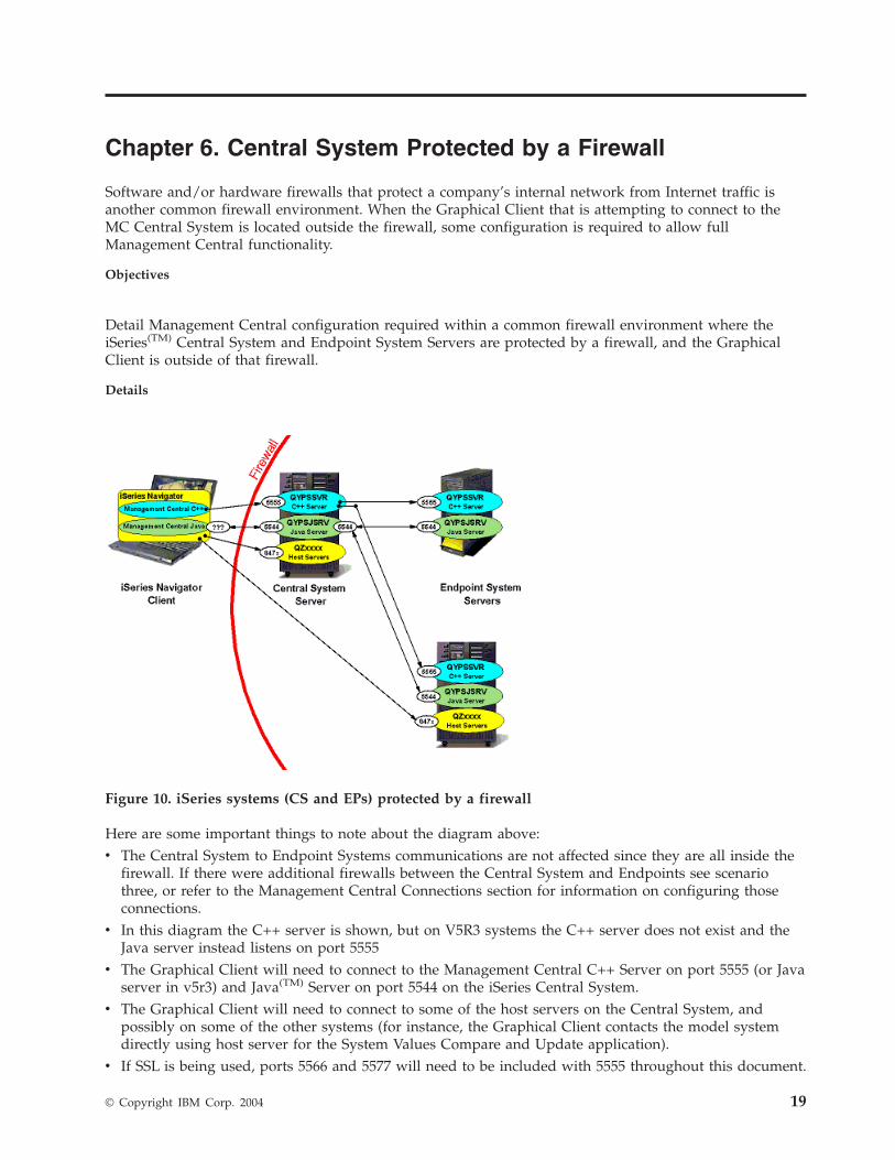
Chapter
6.
Central
System
Protected
by
a
Firewall
Software
and/or
hardware
firewalls
that
protect
a
company’s
internal
network
from
Internet
traffic
is
another
common
firewall
environment.
When
the
Graphical
Client
that
is
attempting
to
connect
to
the
MC
Central
System
is
located
outside
the
firewall,
some
configuration
is
required
to
allow
full
Management
Central
functionality.
Objectives
Detail
Management
Central
configuration
required
within
a
common
firewall
environment
where
the
iSeries(TM)
Central
System
and
Endpoint
System
Servers
are
protected
by
a
firewall,
and
the
Graphical
Client
is
outside
of
that
firewall.
Details
Figure
10.
iSeries
systems
(CS
and
EPs)
protected
by
a
firewall
Here
are
some
important
things
to
note
about
the
diagram
above:
v
The
Central
System
to
Endpoint
Systems
communications
are
not
affected
since
they
are
all
inside
the
firewall.
If
there
were
additional
firewalls
between
the
Central
System
and
Endpoints
see
scenario
three,
or
refer
to
the
Management
Central
Connections
section
for
information
on
configuring
those
connections.
v
In
this
diagram
the
C++
server
is
shown,
but
on
V5R3
systems
the
C++
server
does
not
exist
and
the
Java
server
instead
listens
on
port
5555
v
The
Graphical
Client
will
need
to
connect
to
the
Management
Central
C++
Server
on
port
5555
(or
Java
server
in
v5r3)
and
Java(TM)
Server
on
port
5544
on
the
iSeries
Central
System.
v
The
Graphical
Client
will
need
to
connect
to
some
of
the
host
servers
on
the
Central
System,
and
possibly
on
some
of
the
other
systems
(for
instance,
the
Graphical
Client
contacts
the
model
system
directly
using
host
server
for
the
System
Values
Compare
and
Update
application).
v
If
SSL
is
being
used,
ports
5566
and
5577
will
need
to
be
included
with
5555
throughout
this
document.
©
Copyright
IBM
Corp.
2004
19
The
steps
to
configure
Management
Central
are
slightly
different
depending
on
how
the
firewall
is
configured
to
use
NAT.
Firewall
that
is
not
using
NAT
v
Open
ports
5544
and
5555
on
the
firewall
so
that
the
Graphical
Client
can
connect
with
the
Management
Central
Central
System.
v
Open
the
host
server
ports
on
the
firewall
that
are
needed
for
the
Management
Central
functions
being
used.
For
additional
general
information
on
setting
up
host
servers
to
work
through
a
firewall,
see
http://www-1.ibm.com/servers/eserver/iseries/access/cafirewl.htm
Firewall
that
uses
Static
NAT
v
Follow
the
instructions
(above)
for
a
firewall
that
is
not
using
NAT.
v
Set
the
Central
System
in
iSeries
Navigator
to
connect
to
the
external
IP
address
of
the
CS
(by
making
sure
the
Central
System
under
My
Connections
is
using
the
external
IP
address).
v
Set
QYPS_HOSTNAME
on
the
Central
System
as
described
in
the
Management
Central
Connection
section.
There
are
two
ways
to
do
this:
1.
Set
QYPS_HOSTNAME
of
the
Central
System
to
the
external
IP
address
of
the
Central
System.
This
means
that
any
MC
system
(including
Endpoint
Systems,
which
might
be
inside
the
firewall)
will
connect
to
the
Central
System
by
using
the
external
IP
address.
2.
Set
QYPS_HOSTNAME
to
a
certain
hostname
that
will
resolve
to
the
Central
System’s
external
IP
address
on
external
systems
(for
instance
the
Graphical
Client),
but
will
resolve
to
the
Central
System’s
internal
IP
address
on
internal
systems.
Firewall
that
uses
Dynamic
NAT
If
the
firewall
protecting
the
Central
System
is
using
Dynamic
NAT,
then
the
Graphical
Client
won’t
be
able
to
connect
to
it.
In
fact,
no
system
outside
the
firewall
will
be
able
to
initiate
a
connection
to
the
Central
System
to
use
any
distributed
application.
20
iSeries
Experience
Reports:
Configuring
Management
Central
Connections
for
Firewall
Environments
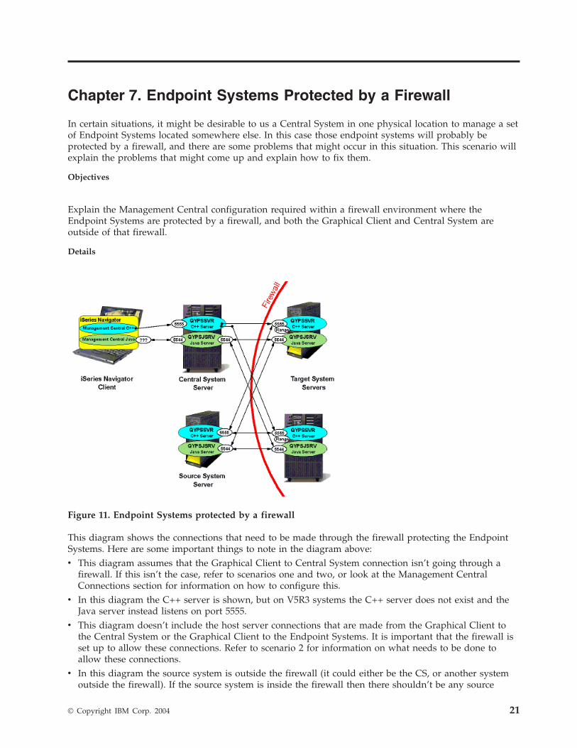
Chapter
7.
Endpoint
Systems
Protected
by
a
Firewall
In
certain
situations,
it
might
be
desirable
to
us
a
Central
System
in
one
physical
location
to
manage
a
set
of
Endpoint
Systems
located
somewhere
else.
In
this
case
those
endpoint
systems
will
probably
be
protected
by
a
firewall,
and
there
are
some
problems
that
might
occur
in
this
situation.
This
scenario
will
explain
the
problems
that
might
come
up
and
explain
how
to
fix
them.
Objectives
Explain
the
Management
Central
configuration
required
within
a
firewall
environment
where
the
Endpoint
Systems
are
protected
by
a
firewall,
and
both
the
Graphical
Client
and
Central
System
are
outside
of
that
firewall.
Details
Figure
11.
Endpoint
Systems
protected
by
a
firewall
This
diagram
shows
the
connections
that
need
to
be
made
through
the
firewall
protecting
the
Endpoint
Systems.
Here
are
some
important
things
to
note
in
the
diagram
above:
v
This
diagram
assumes
that
the
Graphical
Client
to
Central
System
connection
isn’t
going
through
a
firewall.
If
this
isn’t
the
case,
refer
to
scenarios
one
and
two,
or
look
at
the
Management
Central
Connections
section
for
information
on
how
to
configure
this.
v
In
this
diagram
the
C++
server
is
shown,
but
on
V5R3
systems
the
C++
server
does
not
exist
and
the
Java
server
instead
listens
on
port
5555.
v
This
diagram
doesn’t
include
the
host
server
connections
that
are
made
from
the
Graphical
Client
to
the
Central
System
or
the
Graphical
Client
to
the
Endpoint
Systems.
It
is
important
that
the
firewall
is
set
up
to
allow
these
connections.
Refer
to
scenario
2
for
information
on
what
needs
to
be
done
to
allow
these
connections.
v
In
this
diagram
the
source
system
is
outside
the
firewall
(it
could
either
be
the
CS,
or
another
system
outside
the
firewall).
If
the
source
system
is
inside
the
firewall
then
there
shouldn’t
be
any
source
©
Copyright
IBM
Corp.
2004
21
system
connection
problems
(since
the
endpoint
systems
the
source
is
talking
to
are
inside
the
firewall
also),
and
some
of
the
configuration
described
below
won’t
be
necessary.
v
The
CS
will
communicate
with
the
EPs
on
two
ports,
5544
and
5555
v
If
SSL
is
being
used,
ports
5566
and
5577
will
need
to
be
included
with
5555
throughout
this
document.
v
Note
in
the
diagram
that
if
an
application
uses
BDT
(a
C++
extension),
then
each
target
(endpoint)
system
will
pick
a
random
port
to
listen
on,
and
the
source/model
system’s
BDT
server
will
contact
the
endpoint
system
at
that
port
to
transfer
the
data.
v
For
V5R2
and
V5R3
endpoint
systems,
a
range
of
ports
can
be
specified
for
this
BDT
port
using
the
QYPS_MINIMUM_PORT
and
QYPS_MAXIMUM_PORT
properties
described
in
the
Management
Central
Connections
section.
Each
task
that
is
running
needs
a
separate
BDT
port
while
the
task
is
started
up,
so
if
you
could
have
7
Management
Central
applications
that
use
BDT
all
starting
up
on
the
same
target
system
at
the
same
time,
your
range
will
have
to
have
at
least
7
ports.
The
steps
to
configure
Management
Central
are
slightly
different
depending
on
how
the
firewall
is
configured
to
use
NAT.
Firewall
that
is
not
using
NAT
If
the
firewall
doesn’t
use
Network
Address
Translation
(NAT),
then
the
configuration
is
fairly
straightforward
v
Open
ports
5544
and
5555
on
the
firewall
so
that
the
Central
System
and
Source
System
can
connect
with
the
Endpoint
Systems.
v
Refer
to
scenario
2
for
information
on
allowing
the
host
server
connections.
v
Specify
a
range
of
ports
on
each
of
the
target
systems
that
will
be
large
enough
to
have
one
port
for
every
BDT
application
that
is
starting
up
at
the
same
time.
v
Open
this
range
of
ports
on
the
firewall
so
that
the
source/model
system
can
send
data
to
the
target
systems.
Firewall
that
uses
Static
NAT
v
Follow
the
instructions
(above)
for
a
firewall
that
is
not
using
NAT.
v
Make
sure
that
each
Endpoint
System
in
Management
Central
that
is
behind
the
firewall
has
its
external
IP
address
specified
in
the
endpoint
system
list
on
the
Central
System
(since
the
Central
System
won’t
be
able
to
connect
to
the
internal
IP
address
for
any
endpoint
system).
Or,
if
the
lookup
frequency
is
set
to
always,
make
sure
that
on
the
Central
System
the
endpoint
system
names
resolve
to
the
external
IP
address
of
those
endpoint
systems.
v
Set
QYPS_HOSTNAME
on
each
Endpoint
System
as
described
in
the
Management
Central
Connections
section.
This
is
set
in
one
of
two
ways:
1.
Set
QYPS_HOSTNAME
to
the
external
IP
address
of
that
system.
This
means
that
any
MC
system
(including
a
model
system
inside
the
firewall),
will
connect
to
the
Central
System
using
the
external
IP
address.
2.
Set
QYPS_HOSTNAME
to
a
certain
hostname
that
will
resolve
to
that
Endpoint
System’s
external
IP
address
on
external
systems
(for
instance
the
CS),
but
will
resolve
to
that
system’s
internal
IP
address
on
internal
systems.
NOTE:
Setting
QYPS_HOSTNAME
to
a
hostname
(as
opposed
to
an
IP
address)
will
work
well
for
the
Java(TM)
infrastructure
and
extensions,
which
pass
this
QYPS_HOSTNAME
value
to
other
systems
to
be
resolved.
However,
setting
QYPS_HOSTNAME
to
a
hostname
as
opposed
to
an
IP
address
won’t
affect
the
C++
extension
(Bulk
Data
Transfer).
If
QYPS_HOSTNAME
is
actually
set
to
a
hostname
and
not
an
IP
address,
the
Bulk
Data
Transfer
client
on
each
Endpoint
System
will
resolve
this
QYPS_HOSTNAME
to
an
IP
address
first
using
the
DNS
or
host
table
on
that
endpoint
system,
and
then
pass
this
IP
address
on
(instead
of
just
passing
the
hostname
to
a
remote
system
to
be
resolved
there).
Finally,
the
C++
infrastructure
doesn’t
use
this
QYPS_HOSTNAME
value
at
all,
so
there
is
nothing
to
worry
about
there.
22
iSeries
Experience
Reports:
Configuring
Management
Central
Connections
for
Firewall
Environments
Firewall
that
uses
Dynamic
NAT
If
the
firewall
protecting
the
Endpoint
Systems
is
using
Dynamic
NAT,
then
the
Central
System
won’t
be
able
to
connect
to
them.
In
fact,
no
system
outside
the
firewall
will
be
able
to
initiate
a
connection
to
any
of
the
Endpoint
Systems
to
use
any
distributed
application.
Chapter
7.
Endpoint
Systems
Protected
by
a
Firewall
23

24
iSeries
Experience
Reports:
Configuring
Management
Central
Connections
for
Firewall
Environments


����
Printed
in
USA