isl9110, isl9112 datasheet - · pdf fileisl9110, isl9112 fn7649rev 2.00 page 4 of 21 july...
TRANSCRIPT

FN7649Rev 2.00
July 13, 2012
ISL9110, ISL91121.2A High Efficiency Buck-Boost Regulators
DATASHEET
The ISL9110 and ISL9112 are highly-integrated Buck-Boost switching regulators that accept input voltages either above or below the regulated output voltage. Unlike other Buck-Boost regulators, these regulators automatically transition between operating modes without significant output disturbance.
Both parts are capable of delivering up to 1.2A output current, and provide excellent efficiency due to their fully synchronous 4-switch architecture. No-load quiescent current of only 35µA also optimizes efficiency under light-load conditions. Forced PWM and/or synchronization to an external clock may also be selected for noise sensitive applications.
The ISL9110 is designed for standalone applications and supports 3.3V and 5V fixed output voltages or variable output voltages with an external resistor divider. Output voltages as low as 1V, or as high as 5.2V are supported using an external resistor divider.
The ISL9112 supports a broader set of programmable features that may be accessed via an I2C bus interface. With a programmable output voltage range of 1.9V to 5V, the ISL9112 is ideal for applications requiring dynamically changing supply voltages. A programmable slew rate can be selected to provide smooth transitions between output voltage settings.
The ISL9110 and ISL9112 require only a single inductor and very few external components. Power supply solution size is minimized by a tiny 3mmx3mm package and a 2.5MHz switching frequency, which further reduces the size of external components.
Features• Accepts Input Voltages Above or Below Regulated Output
Voltage
• Automatic and Seamless Transitions Between Buck and Boost Modes
• Input Voltage Range: 1.8V to 5.5V
• Output Current: Up to 1.2A
• High Efficiency: Up to 95%
• 35µA Quiescent Current Maximizes Light-load Efficiency
• 2.5MHz Switching Frequency Minimizes External Component Size
• Selectable Forced-PWM Mode and External Synchronization
• I2C Interface (ISL9112)
• Fully Protected for Overcurrent, Over-temperature and Undervoltage
• Small 3mmx3mm TDFN Package
Applications• Regulated 3.3V from a Single Li-Ion Battery
• Smart Phones and Tablet Computers
• Handheld Devices
• Point-of-Load Regulators
Related Literature• See AN1648 “ISL9110IRTNEVAL1Z, ISL9110IRT7EVAL1Z,
ISL9110IRTAEVAL1Z Evaluation Board User Guide”
• See AN1647 “ISL9112IRTNEVAL1Z, ISL9112IRT7EVAL1Z EvaluationBoard User Guide”
FIGURE 1. TYPICAL APPLICATION
VOUT =3.3V/1AVOUT 1
FB 12 C210µF
BATPG
STATUSOUTPUTS
87
PVIN
VIN =1.8V TO 5.5V
VIN
5
6
MODEEN
109
C110µF
ISL9110IRTNZ
GN
D
PG
ND
11 3
LX1
LX2
4
2
L12.2µH
IOUT (A)
EF
FIC
IEN
CY
(%
)
70
75
80
85
90
95
100
0.01 0.05 0.25 1.25
VIN = 5V
VIN = 2.5VVIN = 3V
VOUT = 3.3V
FIGURE 2. EFFICIENCY
FN7649 Rev 2.00 Page 1 of 21July 13, 2012
ISL9110, ISL9112
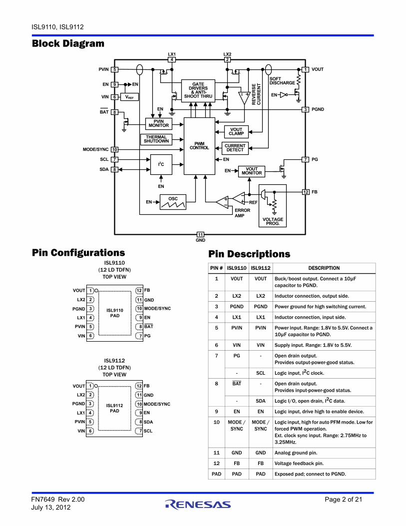
Block Diagram
Pin ConfigurationsISL9110
(12 LD TDFN)TOP VIEW
ISL9112(12 LD TDFN)
TOP VIEW
OSC
ERROR AMP
PVIN
PWM CONTROL
PVIN MONITOR
LX1
VREF
REF
RE
VE
RS
E
CU
RR
EN
T
VOUT5
4 2LX2
GATE DRIVERS & ANTI-
SHOOT THRU6VIN
THERMALSHUTDOWN
I2C
CURRENTDETECT
1
VOUTMONITOR
9
EN
12 FB
3 PGND
11GND
EN
EN
EN
EN EN
EN
VOUTCLAMP
8BAT
10MODE/SYNC
7
8
SCL
SDA
7 PG
VOLTAGEPROG.
EN
SOFTDISCHARGE
VOUT
PVIN
PGND
FB
GND
LX1
LX2
VIN
EN
MODE/SYNC
1
2
3
4
5
6 7
8
9
10
11
12
PG
BAT
ISL9110PAD
SCL
SDA
ISL9112PAD
VOUT
PVIN
PGND
FB
GND
LX1
LX2
VIN
EN
MODE/SYNC
1
2
3
4
5
6 7
8
9
10
11
12
Pin DescriptionsPIN # ISL9110 ISL9112 DESCRIPTION
1 VOUT VOUT Buck/boost output. Connect a 10µF capacitor to PGND.
2 LX2 LX2 Inductor connection, output side.
3 PGND PGND Power ground for high switching current.
4 LX1 LX1 Inductor connection, input side.
5 PVIN PVIN Power input. Range: 1.8V to 5.5V. Connect a 10µF capacitor to PGND.
6 VIN VIN Supply input. Range: 1.8V to 5.5V.
7 PG - Open drain output. Provides output-power-good status.
- SCL Logic input, I2C clock.
8 BAT - Open drain output. Provides input-power-good status.
- SDA Logic I/O, open drain, I2C data.
9 EN EN Logic input, drive high to enable device.
10 MODE /SYNC
MODE /SYNC
Logic input, high for auto PFM mode. Low for forced PWM operation.Ext. clock sync input. Range: 2.75MHz to 3.25MHz.
11 GND GND Analog ground pin.
12 FB FB Voltage feedback pin.
PAD PAD PAD Exposed pad; connect to PGND.
FN7649 Rev 2.00 Page 2 of 21July 13, 2012

ISL9110, ISL9112
Ordering InformationPART NUMBER
(Notes 3, 4)PART
MARKINGVOUT(V)
HICCUPMODE
TEMP RANGE(°C) PACKAGE
PKG. DWG. #
ISL9110IRTNZ (Notes 1, 2) GASA 3.3 Enabled -40 to +85 12 Ld Exposed Pad 3x3 TDFN L12.3x3C
ISL9110IRT7Z (Notes 1, 2) GATA 5.0 Enabled -40 to +85 12 Ld Exposed Pad 3x3 TDFN L12.3x3C
ISL9110IRTAZ (Notes 1, 2) GAUA ADJ. Enabled -40 to +85 12 Ld Exposed Pad 3x3 TDFN L12.3x3C
ISL9112IRTNZ (Notes 1, 2) GAVA 3.3 Enabled -40 to +85 12 Ld Exposed Pad 3x3 TDFN L12.3x3C
ISL9112IRT7Z (Notes 1, 2) GAWA 5.0 Enabled -40 to +85 12 Ld Exposed Pad 3x3 TDFN L12.3x3C
ISL9110BIRTAZ (Notes 1, 2) GBAF ADJ. Disabled -40 to +85 12 Ld Exposed Pad 3x3 TDFN L12.3x3C
ISL9110IRTNEVAL1Z Evaluation Board
ISL9110IRT7EVAL1Z Evaluation Board
ISL9110IRTAEVAL1Z Evaluation Board
ISL9112IRTNEVAL1Z Evaluation Board
ISL9112IRT7EVAL1Z Evaluation Board
NOTES:
1. Add “-T*” suffix for tape and reel. Please refer to TB347 for details on reel specifications.
2. These Intersil Pb-free plastic packaged products employ special Pb-free material sets, molding compounds/die attach materials, and 100% matte tin plate plus anneal (e3 termination finish, which is RoHS compliant and compatible with both SnPb and Pb-free soldering operations). Intersil Pb-free products are MSL classified at Pb-free peak reflow temperatures that meet or exceed the Pb-free requirements of IPC/JEDEC J STD-020.
3. For Moisture Sensitivity Level (MSL), please see device information page for ISL9110 or ISL9112. For more information on MSL please see techbrief TB363.
4. The ISL9110 and ISL9112 can be special ordered with any output voltage between 1.9V and 5.0V in 100mV steps.
FN7649 Rev 2.00 Page 3 of 21July 13, 2012

ISL9110, ISL9112
Table of ContentsAbsolute Maximum Ratings. . . . . . . . . . . . . . . . . . . . . . . . . . . . . . . . . . . . . . . . . . . . . . . . . . . . . . . . . . . . . . . . . . . . . . . . . . . . . . . . . . . . . . . . . . . 5
Thermal Information . . . . . . . . . . . . . . . . . . . . . . . . . . . . . . . . . . . . . . . . . . . . . . . . . . . . . . . . . . . . . . . . . . . . . . . . . . . . . . . . . . . . . . . . . . . . . . . . . 5
Recommended Operating Conditions. . . . . . . . . . . . . . . . . . . . . . . . . . . . . . . . . . . . . . . . . . . . . . . . . . . . . . . . . . . . . . . . . . . . . . . . . . . . . . . . . . . 5
Analog Specifications . . . . . . . . . . . . . . . . . . . . . . . . . . . . . . . . . . . . . . . . . . . . . . . . . . . . . . . . . . . . . . . . . . . . . . . . . . . . . . . . . . . . . . . . . . . . . . . 5
I2C Interface Timing Specification . . . . . . . . . . . . . . . . . . . . . . . . . . . . . . . . . . . . . . . . . . . . . . . . . . . . . . . . . . . . . . . . . . . . . . . . . . . . . . . . . . . . . 7
Typical Performance Curves. . . . . . . . . . . . . . . . . . . . . . . . . . . . . . . . . . . . . . . . . . . . . . . . . . . . . . . . . . . . . . . . . . . . . . . . . . . . . . . . . . . . . . . . . . . 8
Functional Description . . . . . . . . . . . . . . . . . . . . . . . . . . . . . . . . . . . . . . . . . . . . . . . . . . . . . . . . . . . . . . . . . . . . . . . . . . . . . . . . . . . . . . . . . . . . . . 12Functional Overview . . . . . . . . . . . . . . . . . . . . . . . . . . . . . . . . . . . . . . . . . . . . . . . . . . . . . . . . . . . . . . . . . . . . . . . . . . . . . . . . . . . . . . . . . . . . . 12Internal Supply and References. . . . . . . . . . . . . . . . . . . . . . . . . . . . . . . . . . . . . . . . . . . . . . . . . . . . . . . . . . . . . . . . . . . . . . . . . . . . . . . . . . . . 12Enable Input . . . . . . . . . . . . . . . . . . . . . . . . . . . . . . . . . . . . . . . . . . . . . . . . . . . . . . . . . . . . . . . . . . . . . . . . . . . . . . . . . . . . . . . . . . . . . . . . . . . . 12Soft Discharge . . . . . . . . . . . . . . . . . . . . . . . . . . . . . . . . . . . . . . . . . . . . . . . . . . . . . . . . . . . . . . . . . . . . . . . . . . . . . . . . . . . . . . . . . . . . . . . . . . 12POR Sequence and Soft-start. . . . . . . . . . . . . . . . . . . . . . . . . . . . . . . . . . . . . . . . . . . . . . . . . . . . . . . . . . . . . . . . . . . . . . . . . . . . . . . . . . . . . . 12Overcurrent Protection . . . . . . . . . . . . . . . . . . . . . . . . . . . . . . . . . . . . . . . . . . . . . . . . . . . . . . . . . . . . . . . . . . . . . . . . . . . . . . . . . . . . . . . . . . . 12Short Circuit Protection. . . . . . . . . . . . . . . . . . . . . . . . . . . . . . . . . . . . . . . . . . . . . . . . . . . . . . . . . . . . . . . . . . . . . . . . . . . . . . . . . . . . . . . . . . . 12Undervoltage Lockout . . . . . . . . . . . . . . . . . . . . . . . . . . . . . . . . . . . . . . . . . . . . . . . . . . . . . . . . . . . . . . . . . . . . . . . . . . . . . . . . . . . . . . . . . . . . 12PG Status Output (ISL9110 only). . . . . . . . . . . . . . . . . . . . . . . . . . . . . . . . . . . . . . . . . . . . . . . . . . . . . . . . . . . . . . . . . . . . . . . . . . . . . . . . . . . 12BAT Status Output (ISL9110 only). . . . . . . . . . . . . . . . . . . . . . . . . . . . . . . . . . . . . . . . . . . . . . . . . . . . . . . . . . . . . . . . . . . . . . . . . . . . . . . . . . 12Ultrasonic Mode (ISL9112 only). . . . . . . . . . . . . . . . . . . . . . . . . . . . . . . . . . . . . . . . . . . . . . . . . . . . . . . . . . . . . . . . . . . . . . . . . . . . . . . . . . . . 12Thermal Shutdown . . . . . . . . . . . . . . . . . . . . . . . . . . . . . . . . . . . . . . . . . . . . . . . . . . . . . . . . . . . . . . . . . . . . . . . . . . . . . . . . . . . . . . . . . . . . . . 13External Synchronization . . . . . . . . . . . . . . . . . . . . . . . . . . . . . . . . . . . . . . . . . . . . . . . . . . . . . . . . . . . . . . . . . . . . . . . . . . . . . . . . . . . . . . . . . 13Buck-Boost Conversion Topology. . . . . . . . . . . . . . . . . . . . . . . . . . . . . . . . . . . . . . . . . . . . . . . . . . . . . . . . . . . . . . . . . . . . . . . . . . . . . . . . . . . 13PWM Operation . . . . . . . . . . . . . . . . . . . . . . . . . . . . . . . . . . . . . . . . . . . . . . . . . . . . . . . . . . . . . . . . . . . . . . . . . . . . . . . . . . . . . . . . . . . . . . . . . 13PFM Operation . . . . . . . . . . . . . . . . . . . . . . . . . . . . . . . . . . . . . . . . . . . . . . . . . . . . . . . . . . . . . . . . . . . . . . . . . . . . . . . . . . . . . . . . . . . . . . . . . . 13Operation With VIN Close to VOUT. . . . . . . . . . . . . . . . . . . . . . . . . . . . . . . . . . . . . . . . . . . . . . . . . . . . . . . . . . . . . . . . . . . . . . . . . . . . . . . . . . 13Output Voltage Programming . . . . . . . . . . . . . . . . . . . . . . . . . . . . . . . . . . . . . . . . . . . . . . . . . . . . . . . . . . . . . . . . . . . . . . . . . . . . . . . . . . . . . 13Digital Slew Rate Control (ISL9112 only) . . . . . . . . . . . . . . . . . . . . . . . . . . . . . . . . . . . . . . . . . . . . . . . . . . . . . . . . . . . . . . . . . . . . . . . . . . . . 13Register Description (ISL9112) . . . . . . . . . . . . . . . . . . . . . . . . . . . . . . . . . . . . . . . . . . . . . . . . . . . . . . . . . . . . . . . . . . . . . . . . . . . . . . . . . . . . 13I2C Serial Interface (ISL9112) . . . . . . . . . . . . . . . . . . . . . . . . . . . . . . . . . . . . . . . . . . . . . . . . . . . . . . . . . . . . . . . . . . . . . . . . . . . . . . . . . . . . . 14Protocol Conventions . . . . . . . . . . . . . . . . . . . . . . . . . . . . . . . . . . . . . . . . . . . . . . . . . . . . . . . . . . . . . . . . . . . . . . . . . . . . . . . . . . . . . . . . . . . . 14Write Operation . . . . . . . . . . . . . . . . . . . . . . . . . . . . . . . . . . . . . . . . . . . . . . . . . . . . . . . . . . . . . . . . . . . . . . . . . . . . . . . . . . . . . . . . . . . . . . . . . 15Read Operation . . . . . . . . . . . . . . . . . . . . . . . . . . . . . . . . . . . . . . . . . . . . . . . . . . . . . . . . . . . . . . . . . . . . . . . . . . . . . . . . . . . . . . . . . . . . . . . . . 15
Applications Information . . . . . . . . . . . . . . . . . . . . . . . . . . . . . . . . . . . . . . . . . . . . . . . . . . . . . . . . . . . . . . . . . . . . . . . . . . . . . . . . . . . . . . . . . . . . 17Component Selection . . . . . . . . . . . . . . . . . . . . . . . . . . . . . . . . . . . . . . . . . . . . . . . . . . . . . . . . . . . . . . . . . . . . . . . . . . . . . . . . . . . . . . . . . . . . 17Output Voltage Programming, Adj. Version . . . . . . . . . . . . . . . . . . . . . . . . . . . . . . . . . . . . . . . . . . . . . . . . . . . . . . . . . . . . . . . . . . . . . . . . . . 17Feed-Forward Capacitor Selection. . . . . . . . . . . . . . . . . . . . . . . . . . . . . . . . . . . . . . . . . . . . . . . . . . . . . . . . . . . . . . . . . . . . . . . . . . . . . . . . . . 17Non-Adjustable Version FB Pin Connection . . . . . . . . . . . . . . . . . . . . . . . . . . . . . . . . . . . . . . . . . . . . . . . . . . . . . . . . . . . . . . . . . . . . . . . . . . 17Inductor Selection . . . . . . . . . . . . . . . . . . . . . . . . . . . . . . . . . . . . . . . . . . . . . . . . . . . . . . . . . . . . . . . . . . . . . . . . . . . . . . . . . . . . . . . . . . . . . . . 17PVIN and VOUT Capacitor Selection . . . . . . . . . . . . . . . . . . . . . . . . . . . . . . . . . . . . . . . . . . . . . . . . . . . . . . . . . . . . . . . . . . . . . . . . . . . . . . . . 17Application Example 1. . . . . . . . . . . . . . . . . . . . . . . . . . . . . . . . . . . . . . . . . . . . . . . . . . . . . . . . . . . . . . . . . . . . . . . . . . . . . . . . . . . . . . . . . . . . 18Application Example 2. . . . . . . . . . . . . . . . . . . . . . . . . . . . . . . . . . . . . . . . . . . . . . . . . . . . . . . . . . . . . . . . . . . . . . . . . . . . . . . . . . . . . . . . . . . . 18Application Example 3. . . . . . . . . . . . . . . . . . . . . . . . . . . . . . . . . . . . . . . . . . . . . . . . . . . . . . . . . . . . . . . . . . . . . . . . . . . . . . . . . . . . . . . . . . . . 18Recommended PCB Layout . . . . . . . . . . . . . . . . . . . . . . . . . . . . . . . . . . . . . . . . . . . . . . . . . . . . . . . . . . . . . . . . . . . . . . . . . . . . . . . . . . . . . . . 18The TDFN Package Requires Additional PCB Layout Rules for the Thermal Pad . . . . . . . . . . . . . . . . . . . . . . . . . . . . . . . . . . . . . . . . . . . 18General PowerPAD Design Considerations . . . . . . . . . . . . . . . . . . . . . . . . . . . . . . . . . . . . . . . . . . . . . . . . . . . . . . . . . . . . . . . . . . . . . . . . . . 18
Revision History . . . . . . . . . . . . . . . . . . . . . . . . . . . . . . . . . . . . . . . . . . . . . . . . . . . . . . . . . . . . . . . . . . . . . . . . . . . . . . . . . . . . . . . . . . . . . . . . . . . . 19
Products . . . . . . . . . . . . . . . . . . . . . . . . . . . . . . . . . . . . . . . . . . . . . . . . . . . . . . . . . . . . . . . . . . . . . . . . . . . . . . . . . . . . . . . . . . . . . . . . . . . . . . . . . . 19
Package Outline Drawing . . . . . . . . . . . . . . . . . . . . . . . . . . . . . . . . . . . . . . . . . . . . . . . . . . . . . . . . . . . . . . . . . . . . . . . . . . . . . . . . . . . . . . . . . . . 20
FN7649 Rev 2.00 Page 4 of 21July 13, 2012

ISL9110, ISL9112
Absolute Maximum Ratings Thermal InformationPVIN, VIN . . . . . . . . . . . . . . . . . . . . . . . . . . . . . . . . . . . . . . . . . . . -0.3V to 6.5VLX1, LX2 (Note 7) . . . . . . . . . . . . . . . . . . . . . . . . . . . . . . . . . . . . -0.3V to 6.5VFB (adjustable version) . . . . . . . . . . . . . . . . . . . . . . . . . . . . . . . -0.3V to 2.7VFB (fixed VOUT versions) . . . . . . . . . . . . . . . . . . . . . . . . . . . . . . . -0.3V to 6.5VGND, PGND . . . . . . . . . . . . . . . . . . . . . . . . . . . . . . . . . . . . . . . . . -0.3V to 0.3VAll Other Pins . . . . . . . . . . . . . . . . . . . . . . . . . . . . . . . . . . . . . . . -0.3V to 6.5VESD Rating
Human Body Model (Tested per JESD22-A114E) . . . . . . . . . . . . . . . . 3kVMachine Model (Tested per JESD22-A115-A) . . . . . . . . . . . . . . . . . 250V
Latch Up (Tested per JESD-78B; Class 2, Level A) . . . . . . . . . . . . . . 100mA
Thermal Resistance (Typical) JA (°C/W) JC (°C/W)12 Ld TDFN Package (Notes 5, 6) . . . . . . . 42 5.5
Maximum Junction Temperature (Plastic Package) . . . . . . . . . . . .+125°CStorage Temperature Range. . . . . . . . . . . . . . . . . . . . . . . .-65°C to +150°CPb-Free Reflow Profile . . . . . . . . . . . . . . . . . . . . . . . . . . . . . . . see link below
http://www.intersil.com/pbfree/Pb-FreeReflow.asp
Recommended Operating ConditionsTemperature Range . . . . . . . . . . . . . . . . . . . . . . . . . . . . . . . . -40°C to +85°CSupply Voltage Range . . . . . . . . . . . . . . . . . . . . . . . . . . . . . . . . . 1.8V to 5.5VLoad Current Range . . . . . . . . . . . . . . . . . . . . . . . . . . . . . . . . . . . . 0A to 1.2A
CAUTION: Do not operate at or near the maximum ratings listed for extended periods of time. Exposure to such conditions may adversely impact productreliability and result in failures not covered by warranty.
NOTES:
5. JA is measured in free air with the component mounted on a high effective thermal conductivity test board with “direct attach” features. See Tech Brief TB379
6. For JC, the “case temp” location is the center of the exposed metal pad on the package underside.
7. LX1 and LX2 pins can withstand switching transients of -1.5V for 100ns, and 7V for 20ms.
Analog Specifications VVIN = VPVIN = VEN = 3.6V, VOUT = 3.3V, L1 = 2.2µH, C1 = C2 = 10µF, TA = +25°C. Boldface limits apply over the operating temperature range, -40°C to +85°C.
SYMBOL PARAMETER TEST CONDITIONSMIN
(Note 8)TYP
(Note 9)MAX
(Note 8) UNITS
POWER SUPPLY
VIN Input Voltage Range 1.8 5.5 V
VUVLO VIN Undervoltage Lockout Threshold Rising 1.725 1.775 V
Falling 1.550 1.650 V
IVIN VIN Supply Current PFM mode, no external load on Vout (Note 10) 35 60 µA
ISD VIN Supply Current, Shutdown EN = GND, VIN = 3.6V 0.05 1.0 µA
OUTPUT VOLTAGE REGULATION
VOUT Output Voltage Range ISL9110IRTAZ, IOUT = 100mA 1.00 5.20 V
ISL9112, IOUT = 100mA 1.90 5.00 V
Output Voltage Accuracy VIN = 3.7V, VOUT = 3.3V, IOUT = 0mA, PWM mode -2 +2 %
VIN = 3.7V, VOUT = 3.3V, IOUT = 1mA, PFM mode -3 +4 %
VFB FB Pin Voltage Regulation For adjustable output version 0.79 0.80 0.81 V
IFB FB Pin Bias Current For adjustable output version 1 µA
VOUT / VIN
Line Regulation, PWM Mode IOUT = 500mA, VOUT = 3.3V, MODE = GND, VIN step from 2.3V to 5.5V
±0.005 mV/mV
VOUT / IOUT
Load Regulation, PWM Mode VIN = 3.7V, VOUT = 3.3V, MODE = GND, IOUT step from 0mA to 500mA
±0.005 mV/mA
VOUT / VI
Line Regulation, PFM Mode IOUT = 100mA, VOUT = 3.3V, MODE = VIN, VIN step from 2.3V to 5.5V
±12.5 mV/V
VOUT / IOUT
Load Regulation, PFM Mode VIN=3.7V, VOUT = 3.3V, MODE = VIN, IOUT step from 0mA to 100mA
±0.4 mV/mA
VCLAMP Output Voltage Clamp Rising, VIN = 3.6V 5.25 5.95 V
Output Voltage Clamp Hysteresis VIN = 3.6V 400 mV
FN7649 Rev 2.00 Page 5 of 21July 13, 2012

ISL9110, ISL9112
DC/DC SWITCHING SPECIFICATIONS
fSW Oscillator Frequency 2.25 2.50 2.75 MHz
tONMIN Minimum On Time 80 ns
IPFETLEAK LX1 Pin Leakage Current -1 1 µA
INFETLEAK LX2 Pin Leakage Current -1 1 µA
SOFT-START and SOFT DISCHARGE
tSS Soft-start Time Time from when EN signal asserts to when output voltage ramp starts.
1 ms
Time from when output voltage ramp starts to when output voltage reaches 95% of its nominal value with device operating in buck mode.VIN = 4V, VOUT = 3.3V, IO = 200mA
1 ms
Time from when output voltage ramp starts to when output voltage reaches 95% of its nominal value with device operating in boost mode.VIN = 2V, VOUT = 3.3V, IO = 200mA
2 ms
RDISCHG VOUT Soft-Discharge ON-Resistance VIN = 3.6V, EN < VIL 120
POWER MOSFET
RDSON_P P-Channel MOSFET ON-Resistance VIN = 3.6V, IO = 200mA 0.12 0.17
VIN = 2.5V, IO = 200mA 0.15 0.23
RDSON_N N-Channel MOSFET ON-Resistance VIN = 3.6V, IO = 200mA 0.10 0.15
VIN = 2.5V, IO = 200mA 0.13 0.23
IPK_LMT P-Channel MOSFET Peak Current Limit VIN = 3.6V 2.0 2.4 2.8 A
PFM/PWM TRANSITION
Load Current Threshold, PFM to PWM VIN = 3.6V, VOUT = 3.3V 200 mA
Load Current Threshold, PWM to PFM VIN = 3.6V, VOUT = 3.3V 75 mA
External Synchronization Frequency Range 2.75 3.25 MHz
Thermal Shutdown 155 °C
Thermal Shutdown Hysteresis 30 °C
BATTERY MONITOR AND POWER GOOD COMPARATORS
VTBMON Battery Monitor Voltage Threshold 1.85 2.0 2.15 V
VHBMON Battery Monitor Voltage Hysteresis 100 mV
tBMON Battery Monitor Debounce Time 25 µs
PG Delay Time (Rising) 1 ms
PG Delay Time (Falling) 20 µs
Minimum Supply Voltage for Valid PG Signal EN = VIN 1.2 V
PGRNGLR PG Range - Lower (Rising) Percentage of programmed voltage 90 %
PGRNGLF PG Range - Lower (Falling) Percentage of programmed voltage 87 %
PGRNGUR PG Range - Upper (Rising) Percentage of programmed voltage 112 %
PGRNGUF PG Range - Upper (Falling) Percentage of programmed voltage 110 %
Compliance Voltage - PG, BAT VIN = 3.6V, ISINK = 1mA 0.3 V
Analog Specifications VVIN = VPVIN = VEN = 3.6V, VOUT = 3.3V, L1 = 2.2µH, C1 = C2 = 10µF, TA = +25°C. Boldface limits apply over the operating temperature range, -40°C to +85°C. (Continued)
SYMBOL PARAMETER TEST CONDITIONSMIN
(Note 8)TYP
(Note 9)MAX
(Note 8) UNITS
FN7649 Rev 2.00 Page 6 of 21July 13, 2012

ISL9110, ISL9112
LOGIC INPUTS
ILEAK Input Leakage 0.05 1 µA
VIH Input HIGH Voltage 1.4 V
VIL Input LOW Voltage 0.4 V
Analog Specifications VVIN = VPVIN = VEN = 3.6V, VOUT = 3.3V, L1 = 2.2µH, C1 = C2 = 10µF, TA = +25°C. Boldface limits apply over the operating temperature range, -40°C to +85°C. (Continued)
SYMBOL PARAMETER TEST CONDITIONSMIN
(Note 8)TYP
(Note 9)MAX
(Note 8) UNITS
I2C Interface Timing Specification For SCL, and SDA pins, unless otherwise noted.
SYMBOL PARAMETER TEST CONDITIONSMIN
(Note 8)TYP
(Note 9)MAX
(Note 8) UNITS
Cpin Pin Capacitance (Note 11) 15 pF
fSCL SCL Frequency (Note 11) 400 kHz
tsp Pulse Width Suppression Time at SDA and SCL Inputs
Any pulse narrower than the max spec is suppressed (Note 11)
50 ns
tAA SCL Falling Edge to SDA Output Data Valid SCL falling edge crossing VIL, until SDA exits the VIL to VIH window (Note 11)
900 ns
tBUF Time the Bus Must be Free Before the Start of a New Transmission
SDA crossing VIH during a STOP condition, to SDA crossing VIH during the following START condition (Note 11)
1300 ns
tLOW Clock LOW Time Measured at the VIL crossings (Note 11) 1300 ns
tHIGH Clock HIGH Time Measured at the VIH crossings (Note 11) 600 ns
tSU:STA START Condition Set-up Time SCL rising edge to SDA falling edge; both crossing VIH (Note 11)
600 ns
tHD:STA START Condition Hold Time From SDA falling edge crossing VIL to SCL falling edge crossing VIH (Note 11)
600 ns
tSU:DAT Input Data Set-up Time From SDA exiting the VIL to VIH window, to SCL rising edge crossing VIL (Note 11)
100 ns
tHD:DAT Input Data Hold Time From SCL rising edge crossing VIH to SDA entering the VIL to VIH window (Note 11)
0 ns
tSU:STO STOP Condition Set-up Time From SCL rising edge crossing VIH, to SDA rising edge crossing VIL (Note 11)
600 ns
tHD:STO STOP Condition Hold Time for Read, or Volatile Only Write
From SDA rising edge to SCL falling edge; both crossing VIH (Note 11)
1300 ns
tDH Output Data Hold Time From SCL falling edge crossing VIL, until SDA enters the VIL to VIH window (Note 11)
0 ns
tR SDA and SCL Rise Time From VIL to VIH (Note 11) 20 + 0.1 x Cb 250 ns
tF SDA and SCL Fall Time From VIH to VIL (Note 11) 20 + 0.1 x Cb 250 ns
Cb Capacitive Loading of SDA or SCL Total on-chip and off-chip (Note 11) 10 400 pF
Rpu SDA and SCL Bus Pull-up Resistor Off-chip Maximum is determined by tR and tFFor Cb = 400pF, max is about 2k~2.5kFor Cb = 40pF, max is about 15k~20k(Note 11)
1 k
NOTES:
8. Parameters with MIN and/or MAX limits are 100% tested at +25°C, unless otherwise specified. Temperature limits established by characterization and are not production tested.
9. Typical values are for TA = +25°C and VIN = 3.6V.
10. Quiescent current measurements are taken when the output is not switching.
11. ISL9112 only. Limits established by characterization and are not production tested.
FN7649 Rev 2.00 Page 7 of 21July 13, 2012
ISL9110, ISL9112
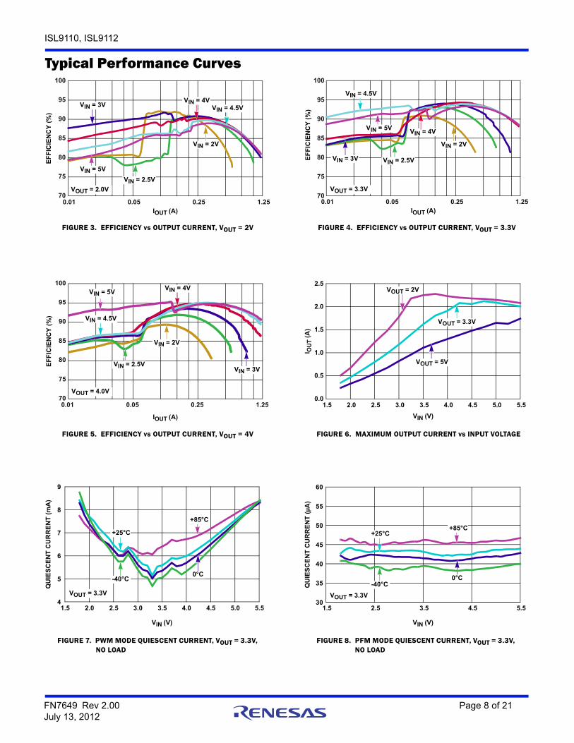
Typical Performance Curves
FIGURE 3. EFFICIENCY vs OUTPUT CURRENT, VOUT = 2V FIGURE 4. EFFICIENCY vs OUTPUT CURRENT, VOUT = 3.3V
FIGURE 5. EFFICIENCY vs OUTPUT CURRENT, VOUT = 4V FIGURE 6. MAXIMUM OUTPUT CURRENT vs INPUT VOLTAGE
FIGURE 7. PWM MODE QUIESCENT CURRENT, VOUT = 3.3V, NO LOAD
FIGURE 8. PFM MODE QUIESCENT CURRENT, VOUT = 3.3V, NO LOAD
70
75
80
85
90
95
100
0.01 0.05 0.25 1.25IOUT (A)
EF
FIC
IEN
CY
(%
)
VIN = 5V
VIN = 4.5V
VIN = 2.5V
VIN = 3V
VIN = 2V
VOUT = 2.0V
VIN = 4V
IOUT (A)
EF
FIC
IEN
CY
(%
)
70
75
80
85
90
95
100
0.01 0.05 0.25 1.25
VIN = 5V
VIN = 4.5V
VIN = 4V
VIN = 2.5V
VIN = 2V
VOUT = 3.3V
VIN = 3V
70
75
80
85
90
95
100
0.01 0.05 0.25 1.25
IOUT (A)
EF
FIC
IEN
CY
(%
)
VIN = 5V
VIN = 4.5V
VIN = 2.5VVIN = 3V
VIN = 2V
VOUT = 4.0V
VIN = 4V
0.0
0.5
1.0
1.5
2.0
2.5
1.5 2.0 2.5 3.0 3.5 4.0 4.5 5.0 5.5
I OU
T (
A)
VIN (V)
VOUT = 5V
VOUT = 3.3V
VOUT = 2V
4
5
6
7
8
9
1.5 2.0 2.5 3.0 3.5 4.0 4.5 5.0 5.5
QU
IES
CE
NT
CU
RR
EN
T (
mA
)
VIN (V)
-40°C0°C
+25°C
+85°C
VOUT = 3.3V
30
35
40
45
50
55
60
1.5 2.5 3.5 4.5 5.5
-40°C0°C
+25°C+85°C
VOUT = 3.3V
QU
IES
CE
NT
CU
RR
EN
T (
µA
)
VIN (V)
FN7649 Rev 2.00 Page 8 of 21July 13, 2012

ISL9110, ISL9112
FIGURE 9. STEADY STATE TRANSITION FROM BUCK TO BOOST FIGURE 10. STEADY STATE TRANSITION FROM BOOST TO BUCK
FIGURE 11. STEADY STATE VIN NEAR VOUT FIGURE 12. INPUT TRANSIENT
FIGURE 13. TRANSIENT LOAD RESPONSE FIGURE 14. TRANSIENT LOAD RESPONSE
Typical Performance Curves (Continued)
LX15V/DIV
5V/DIVLX2
50mV/DIVVOUT
0.5A/DIVCURRENT
INDUCTOR
400µs/DIV
VIN = 4.5V 2.5VVOUT = 3.3V
IOUT = 500mALX1
5V/DIV
5V/DIVLX2
50mV/DIVVOUT
0.5A/DIVCURRENT
INDUCTOR
400µs/DIV
VIN = 2.5V 4.5VVOUT = 3.3V
IOUT = 500mA
LX12V/DIV
2V/DIVLX2
50mV/DIVVOUT
0.5A/DIVCURRENT
INDUCTOR
400ns/DIV
VIN = 3.6VVOUT = 3.3VIOUT = 0.6A
50mV/DIVVOUT
2V/DIVVIN
50µs/DIV
VIN = 4.5V 2.5V 4.5VVOUT = 3.3V
IOUT = 400mA
0.1V/DIVVOUT
0.5A/DIVCURRENT
INDUCTOR
100µs/DIV
LX15V/DIV
5V/DIVLX2
VIN = 2VVOUT = 3.3V
IOUT = 0A TO 0.4A
LX15V/DIV
5V/DIVLX2
0.1V/DIVVOUT
0.5A/DIVCURRENT
INDUCTOR
100µs/DIV
VIN = 3.6VVOUT = 3.3V
IOUT = 0A TO 1A
FN7649 Rev 2.00 Page 9 of 21July 13, 2012

ISL9110, ISL9112
FIGURE 15. SWITCHING WAVEFORMS, BOOST MODE FIGURE 16. SWITCHING WAVEFORMS, BUCK MODE
FIGURE 17. NFET RDS(ON) vs INPUT VOLTAGE FIGURE 18. PFET RDS(ON) vs INPUT VOLTAGE
FIGURE 19. VREF vs TEMPERATURE, TA = -40°C TO +85°C FIGURE 20. OUTPUT VOLTAGE vs VIN VOLTAGE (VOUT = 3.3V)
Typical Performance Curves (Continued)
LX12V/DIV
2V/DIVLX2
10mV/DIVVOUT
0.5A/DIVCURRENT
INDUCTOR
400ns/DIV
VIN = 2.5VVOUT = 3.3V
IOUT = 500mA
LX15V/DIV
5V/DIVLX2
10mV/DIVVOUT
0.5A/DIVCURRENT
INDUCTOR
400ns/DIV
VIN = 4.5VVOUT = 3.3V
IOUT = 1A
0.00
0.05
0.10
0.15
0.20
0.25
1.5 2.0 2.5 3.0 3.5 4.0 4.5 5.0 5.5
-40°C0°C
+40°C
+85°C
RD
S(O
N)
(Ω)
VIN (V)
0.00
0.05
0.10
0.15
0.20
0.25
1.5 2.0 2.5 3.0 3.5 4.0 4.5 5.0 5.5
-40°C0°C
+40°C
+85°C
RD
S(O
N)
(Ω)
VIN (V)
0.790
0.795
0.800
0.805
0.810
-40 -20 0 20 40 60 80 100
VR
EF (
V)
TEMPERATURE (°C)
3.270
3.275
3.280
3.285
3.290
1.5 2.5 3.5 4.5 5.5
IOUT = 0.1A(PFM)
NO LOAD(PFM)
IOUT = 1.2A(PWM)
IOUT = 0.8A (PWM)
IOUT = 0.4A (PWM)
VO
UT (
V)
VIN (V)
FN7649 Rev 2.00 Page 10 of 21July 13, 2012

ISL9110, ISL9112
FIGURE 21. SOFT-START, VIN = 4V, VOUT = 3.3V FIGURE 22. SOFT-START, VIN = 2V, VOUT = 3.3V
FIGURE 23. OUTPUT VOLTAGE vs LOAD CURRENT (VIN = 2.5V, VOUT = 3.3V, AUTO PFM/PWM MODE)
FIGURE 24. OUTPUT VOLTAGE vs LOAD CURRENT (VIN = 4.5V, VOUT = 3.3V, AUTO PFM/PWM MODE)
FIGURE 25. OUTPUT SOFT-DISCHARGE FIGURE 26. DIGITAL SLEW OPERATION (ISL9112)
Typical Performance Curves (Continued)
LX12V/DIV
2V/DIVLX2
2V/DIVVOUT
2V/DIVEN
400µs/DIV
VIN = 4VVOUT = 3.3VIOUT = 200mA LX1
2V/DIV
2V/DIVLX2
2V/DIVVOUT
2V/DIVEN
400µs/DIV
VIN = 2VVOUT = 3.3VIOUT = 200mA
3.280
3.285
3.290
3.295
3.300
3.305
3.310
3.315
0.0 0.1 0.2 0.3 0.4 0.5
VO
UT
(V
)
IOUT (mA)
LOAD CURRENT RISING
LOAD CURRENT FALLING
3.280
3.285
3.290
3.295
3.300
3.305
3.310
0.0 0.1 0.2 0.3 0.4 0.5
VO
UT
(V
)
IOUT (mA)
LOAD CURRENT RISING
LOAD CURRENT FALLING
1V/DIVVOUT
1V/DIVEN
4ms/DIV
VIN = 3.7VVOUT = 3.3V
200mV/DIVVOUT
2V/DIVSCL
1ms/DIV
2V/DIVSDA
VIN = 5VVOUT = 3.0V 4.0V 3.0V
SLEWRATE = 0b111
FN7649 Rev 2.00 Page 11 of 21July 13, 2012

ISL9110, ISL9112
Functional DescriptionFunctional OverviewRefer to the “Block Diagram” on page 2. The ISL9110, ISL9112 implements a complete buck boost switching regulator, with PWM controller, internal switches, references, protection circuitry, and control inputs.
The PWM controller automatically switches between buck and boost modes as necessary to maintain a steady output voltage, with changing input voltages and dynamic external loads.
The ISL9110 provides output-power-good and input-power-good open-drain status outputs on pins 7 and 8. In the ISL9112, these pins are used for an I2C interface, allowing programmable output voltage and access to the ultrasonic mode and slew rate limit control bits.
Internal Supply and ReferencesReferring to the “Block Diagram” on page 2, the ISL9110, ISL9112 provides two power input pins. The PVIN pin supplies input power to the DC/DC converter, while the VIN pin provides operating voltage source required for stable VREF generation. Separate ground pins (GND and PGND) are provided to avoid problems caused by ground shift due to the high switching currents.
Enable InputA master enable pin EN allows the device to be enabled. Driving EN low invokes a power-down mode, where most internal device functions, including input and output power good detection, are disabled.
Soft DischargeWhen the device is disabled by driving EN low, an internal resistor between VOUT and GND is activated. This internal resistor has typical 120Ω resistance.
POR Sequence and Soft-startBringing the EN pin high allows the device to power-up. A number of events occur during the start-up sequence. The internal voltage reference powers up, and stabilizes. The device then starts operating. There is a typical 1ms delay between assertion of the EN pin and the start of switching regulator soft-start ramp.
The soft-start feature minimizes output voltage overshoot and input inrush currents. During soft-start, the reference voltage is ramped to provide a ramping VOUT voltage. While output voltage is lower than approximately 20% of the target output voltage, switching frequency is reduced to a fraction of the normal switching frequency to aid in producing low duty cycles necessary to avoid input inrush current spikes. Once the output voltage exceeds 20% of the target voltage, switching frequency is increased to its nominal value.
When the target output voltage is higher than the input voltage, there will be a transition from buck mode to boost mode during the soft-start sequence. At the time of this transition, the ramp rate of the reference voltage is decreased, such that the output voltage slew rate is decreased. This provides a slower output voltage slew rate.
The VOUT ramp time is not constant for all operating conditions. Soft-start into boost mode will take longer than soft-start into buck mode. The total soft-start time into buck operating mode is typically 2ms, whereas the typical soft-start time into boost mode operating mode is typically 3ms. Increasing the load current will increase these typical soft-start times.
Overcurrent ProtectionWhen the current in the P-Channel MOSFET is sensed to reach the current limit for 16 consecutive switching cycles, the internal protection circuit is triggered, and switching is stopped for approximately 20ms. The device then performs a soft-start cycle. If the external output overcurrent condition exists after the soft-start cycle, the device will again detect 16 consecutive switching cycles reaching the peak current threshold. The process will repeat as long as the external overcurrent condition is present. This behavior is called ‘hiccup mode’.
Short Circuit ProtectionThe ISL9110, ISL9112 provides short-circuit protection by monitoring the feedback voltage. When feedback voltage is sensed to be lower than a certain threshold, the PWM oscillator frequency is reduced in order to protect the device from damage. The P-Channel MOSFET peak current limit remains active during this state.
Undervoltage LockoutThe undervoltage lockout (UVLO) feature prevents abnormal operation in the event that the supply voltage is too low to guarantee proper operation. When the VIN voltage falls below the UVLO threshold, the regulator is disabled.
PG Status Output (ISL9110 only)An open drain output-power-good signal is provided in the ISL9110. An internal window comparator is used to detect when VOUT is significantly higher or lower than the target output voltage. The PG output will be driven low when sensed VOUT voltage is outside of this ‘power good’ window. When VOUT voltage is inside the ‘power good’ window, the PG pin goes Hi-Z.
The PG detection circuit detects this condition by monitoring voltage on the FB pin. Hysteresis is provided for the upper and lower PG thresholds to avoid oscillation of the PG output.
BAT Status Output (ISL9110 only)The ISL9110 provides an open drain input-power-good status output. The BAT status pin will be driven low when VIN rises above the VTBMON threshold. The BAT status output goes Hi-Z when VBAT falls below the VTBMON threshold. Hysteresis is provided for the VTBMON threshold to avoid oscillation of the BAT output.
Ultrasonic Mode (ISL9112 only)The ISL9112 provides an ultrasonic mode that can be enabled through I2C control by setting the ULTRA bit in the control register.
In ultrasonic mode, the PFM switching frequency is forced to be above the audio frequency range.
This ultrasonic mode applies only to PFM mode operation. With the ULTRA bit set to ‘1’, PFM mode switching frequency is forced
FN7649 Rev 2.00 Page 12 of 21July 13, 2012

ISL9110, ISL9112
well above the audio frequency range (fSW becomes typically 60kHz). This mode of operation, however, reduces the efficiency at light load.
Thermal ShutdownA built-in thermal protection feature protects the ISL9110, ISL9112 if the die temperature reaches +155°C (typical). At this die temperature, the regulator is completely shut down. The die temperature continues to be monitored in this thermal-shutdown mode. When the die temperature falls to +125°C (typical), the device will resume normal operation.
When exiting thermal shutdown, the ISL9110, ISL9112 will execute its soft-start sequence.
External SynchronizationAn external sync feature is provided. Applying a clock signal with a frequency between 2.75MHz and 3.25MHz at the MODE/SYNC input forces the ISL9110, ISL9112 to synchronize to this external clock. The MODE/SYNC input supports standard logic levels.
Buck-Boost Conversion TopologyThe ISL9110, ISL9112 operates in either buck or boost mode. When operating in conditions where VIN is close to VOUT, the ISL9110 alternates between buck and boost mode as necessary to provide a regulated output voltage.
Figure 27 shows a simplified diagram of the internal switches and external inductor.
PWM OperationIn buck PWM mode, Switch D is continuously closed, and Switch C is continuously open. Switches A and B operate as a synchronous buck converter when in this mode.
In boost PWM mode, Switch A remains closed and Switch B remains open. Switches C and D operate as a synchronous boost converter when in this mode.
PFM OperationDuring PFM operation in buck mode, Switch D is continuously closed, and Switch C is continuously open. Switches A and B operate in discontinuous mode during PFM operation.
During PFM operation in boost mode, the ISL9110, ISL9112 closes Switch A and Switch C to ramp up the current in the inductor. When inductor current reaches a certain threshold, the device turns off Switches A and C, then turns on Switches B and D. With Switches B and D closed, output voltage increases as the inductor current ramps down.
In most operating conditions, there will be multiple PFM pulses to charge up the output capacitor. These pulses continue until VOUT has achieved the upper threshold of the PFM hysteretic controller. Switching then stops, and remains stopped until VOUT decays to the lower threshold of the hysteretic PFM controller.
Operation With VIN Close to VOUTWhen the output voltage is close to the input voltage, the ISL9110, ISL9112 will rapidly and smoothly switch from boost to buck mode as needed to maintain the regulated output voltage. This behavior provides excellent efficiency and very low output voltage ripple.
Output Voltage ProgrammingThe ISL9110 is available in fixed and adjustable output voltage versions. To use the fixed output version, the VOUT pin must be connected directly to FB.
In the adjustable output voltage version (ISL9110IRTAZ), an external resistor divider is required to program the output voltage. The FB pin has very low input leakage current, so it is possible to use large value resistors (e.g. R1 = 1MΩ and R2 = 324kΩ) in the resistor divider connected to the FB input.
The ISL9112 is available in a fixed output version only. The factory programmed output voltage can be changed via the I2C interface. Details about the ISL9112 programmable VOUT voltage can be found in the section “Register Description (ISL9112)” on page 13.
Digital Slew Rate Control (ISL9112 only)When changing voltages using the I2C interface, the ISL9110 can be programmed to control the rate of voltage increase or decrease as it transitions from one voltage setting to the next.
The default configuration disables this digital slew rate feature. To enable the slew rate feature, an I2C command is sent to the ISL9112, changing the value of the SLEWRATE bit field to a value other than 0b000. Details about the digital slew rate settings can be found in Table 3.
Register Description (ISL9112)The ISL9112 has a two I2C accessible control registers that are used to set output voltage, operating mode, and digital slew rate. These registers can be read and written to at any time that the ISL9112 is enabled. Attempts to communicate with the ISL9112 via its I2C interface when the ISL9112 is disabled (EN = Low) are not supported.
FIGURE 27. BUCK BOOST TOPOLOGY
5PVIN 1 VOUT
4 2SWITCH A SWITCH D
SWITCH B SWITCH C
LX1 LX2
L1
FN7649 Rev 2.00 Page 13 of 21July 13, 2012

ISL9110, ISL9112
Bits DCDOUT[4:0] set the output voltage, as shown in Equation 1 and Table 2. The ISL9112 output voltage range is 1.9V to 5.0V.
A safety mechanism is provided to prevent unintentional changes to the output voltage by errant host software. The MSB of the control register (I2CEN bit, see Table 1) must be set to ‘1’ in order for the ISL9112 to recognize the I2C command as valid. If a value of ‘0’ is written to this bit, the I2C command is ignored, and output voltage and operating mode will revert to the factory programmed default (3.3V for ISL9112IRTNZ; 5V for ISL9112IRT7Z).
I2C Serial Interface (ISL9112)The ISL9112 supports a bi-directional bus oriented protocol. The protocol defines any device that sends data onto the bus as a transmitter and the receiving device as the receiver. The device controlling the transfer is the master and the device being controlled is the slave. The master always initiates data transfers and provides the clock for both transmit and receive operations. Therefore, the ISL9112 operates as a slave device in all applications.
All communication over the I2C interface is conducted by sending the MSB of each byte of data first.
Protocol ConventionsData states on the SDA line can change only during SCL LOW periods. SDA state changes during SCL HIGH are reserved for indicating START and STOP conditions (see Figure 28). Upon power-up of the ISL9112, the SDA pin is in the input mode.
TABLE 1. REGISTER ADDRESS 0x00: VOLTAGE CONTROL
BIT NAME TYPE RESET DESCRIPTION
4:0 DCDOUT R/W 00000 VOUT programming. See Table 2.
5 ULTRA R/W 0 Ultrasonic mode select. Not applicable in forced PWM mode:0: Ultrasonic feature disabled1: Ultrasonic feature enabled
6 Reserved R/W 0
7 I2CEN R/W 0 I2C programming enable bit:0: Device ignores I2C command, and uses last programmed DCDOUT and ULTRA settings; or if no I2C communication has occurred since POR, the factory programmed default DCDOUT and ULTRA settings are used.1: Device uses the I2C programmed DCDOUT and ULTRA settings.
TABLE 2. DCDOUT[4:0] VALUE vs OUTPUT VOLTAGE
DCDOUT[4:0]OUTPUT VOLTAGE
(V)
0b00000 1.9
0b00001 2.0
0b00010 2.1
0b00011 2.2
0b00100 2.3
0b00101 2.4
0b00110 2.5
0b00111 2.6
0b01000 2.7
0b01001 2.8
0b01010 2.9
0b01011 3.0
0b01100 3.1
0b01101 3.2
0b01110 3.3
0b01111 3.4
0b10000 3.5
0b10001 3.6
VOUT 1.9V n 0.1V + where n = 0 to 31= (EQ. 1)
0b10010 3.7
0b10011 3.8
0b10100 3.9
0b10101 4.0
0b10110 4.1
0b10111 4.2
0b11000 4.3
0b11001 4.4
0b11010 4.5
0b11011 4.6
0b11100 4.7
0b11101 4.8
0b11110 4.9
0b11111 5.0
TABLE 3. REGISTER ADDRESS 0x01: SLEW RATE CONTROL
BIT NAME TYPE RESET DESCRIPTION
2:0 SLEWRATE R/W 000 Slew rate control (typ), expressed as µs per LSB change in DCDOUT value:0b000 = 0µs/LSB0b001 = 1.5µs/LSB0b010 = 3.1µs/LSB0b011 = 6.3µs/LSB0b100 = 12.5µs/LSB0b101 = 25µs/LSB0b110 = 50µs/LSB0b111 = 100µ /LSB
7:3 Reserved R/W 00000
TABLE 2. DCDOUT[4:0] VALUE vs OUTPUT VOLTAGE (Continued)
DCDOUT[4:0]OUTPUT VOLTAGE
(V)
FN7649 Rev 2.00 Page 14 of 21July 13, 2012

ISL9110, ISL9112
All I2C interface operations must begin with a START condition, which is a HIGH to LOW transition of SDA while SCL is HIGH. The ISL9112 continuously monitors the SDA and SCL lines for the START condition and does not respond to any command until this condition is met (see Figure 28). A START condition is ignored during the power-up sequence and when EN input is low.
All I2C interface operations must be terminated by a STOP condition, which is a LOW to HIGH transition of SDA while SCL is HIGH (see Figure 28). A STOP condition at the end of a write operation initiates the reconfiguration of the ISL9112’s voltage feedback loop as necessary to provide the programmed output voltage.
An ACK, Acknowledge, is a software convention used to indicate a successful data transfer. The transmitting device, either master or slave, releases the SDA bus after transmitting eight bits. During the ninth clock cycle, the receiver pulls the SDA line LOW to acknowledge the reception of the eight bits of data (see Figure 29).
The ISL9112 responds with an ACK after recognition of a START condition followed by a valid Identification Byte, and once again after successful receipt of a Register Address Byte. The ISL9112 also responds with an ACK after receiving a Data Byte of a write operation. The master must respond with an ACK after receiving a Data Byte of a read operation.
A valid Identification Byte contains 0b0011100 as the seven MSBs, corresponding to the ISL9112 I2C Slave Address. The LSB of the Identification byte is the Read/Write bit. Its value is “1” for a Read operation, and “0” for a Write operations (see Table 4).
Write OperationA Write operation requires a START condition, followed by a valid Identification Byte (containing the Slave Address with the R/W bit set to 0), a valid Register Address Byte, a Data Byte, and a STOP condition. After each of the three bytes, the ISL9112 responds with an ACK. The master will then send a STOP to complete the command.
STOP conditions that terminate write operations must be sent by the master after sending at least 1 full data byte and its associated ACK signal. If a STOP condition is issued in the middle of a data byte, or before 1 full data byte + ACK is sent, then the ISL9112 will ignore the command, and not change output voltage or other settings.
Read OperationA Read operation is shown in Figure 31. It consists of 4 bytes. The host generates a START condition, then transmits an Identification byte (containing the Slave Address with the R/W bit set to 0). The ISL9112 responds with an ACK. The host then transmits the Register Address byte, and the ISL9112 responds with another ACK.
The host then generates a Repeat START condition, or a STOP condition followed by a START condition. The host then transmits an Identification byte (containing the Slave Address with the R/W bit set to 1). The ISL9112 responds with an ACK, indicating it is ready to begin providing the requested data.
The ISL9112 then transmits the data byte by asserting control of the SDA pin while the host generates clock pulses on the SCL pin. When transmission of the data byte is complete, the host generates a NACK condition followed by a STOP condition. This completes the I2C Read operation.
The ISL9112 register map supports only one register, at register address 0x00. Attempts to read other register addresses are not supported, and should not be attempted. Similarly, I2C block reads and writes are not supported by the ISL9112. The ISL9112 has only one register to read or write, therefore block reads and writes are not necessary.
TABLE 4. IDENTIFICATION BYTE FORMAT
0 0 1 1 1 0 0 R/W
(MSB) (LSB)
SDA
SCL
START DATA DATA STOPSTABLE CHANGE
DATASTABLE
FIGURE 28. VALID DATA CHANGES, START AND STOP CONDITIONS
FN7649 Rev 2.00 Page 15 of 21July 13, 2012

ISL9110, ISL9112
SDA OUTPUT FROMTRANSMITTER
SDA OUTPUTFROM RECEIVER
81 9
START ACK
SCL FROMMASTER
HIGH IMPEDANCE
FIGURE 29. ACKNOWLEDGE RESPONSE FROM RECEIVER
HIGH IMPEDANCE
FIGURE 30. I2C REGISTER WRITE PROTOCOL
S 0 A PD A TA B Y TE
R /W
A
S Y S TE M H O S T
IS L 9112
A – A C K N O W LE D G EN – N O T A C K N O W L E D G ES – S T A R TP – S T O P
A
IS L 9112 I2C W R ITE P R O TO C O L
D C D V1 (5 B ITS )
UL
TR
A
WA
RN
I2C
_EN
0 0 0 0 0 0 0 0
R E G IS TE RA D D R E S S = 0x00
I2C S L A V E7-B IT A D D R E S S
0 0 1 1 1 0 0
FIGURE 31. I2C REGISTER READ PROTOCOL
S 0 A P
R/W
S 1
R/W
NDATA BYTEA A
ISL9112 I2C READ PROTOCOL #1
DCDV1 (5 BITS)
UL
TR
A
WA
RN
I2C
_EN
S 0 A P
R/W
S 1
R/W
NDATA BYTEA A
ISL9112 I2C READ PROTOCOL #2
DCDV1 (5 BITS)
UL
TR
A
WA
RN
I2C
_EN
P
0 0 0 0 0 0 0 0
0 0 0 0 0 0 0 0
REGISTERADDRESS = 0x00
REGISTERADDRESS = 0x00
I2C SLAVE7-BIT ADDRESS
I2C SLAVE7-BIT ADDRESS
I2C SLAVE7-BIT ADDRESS
I2C SLAVE7-BIT ADDRESS
0 0 1 1 1 0 0
0 0 1 1 1 0 0 0 0 1 1 1 0 0
0 0 1 1 1 0 0SYSTEM HOST
ISL9112
A – ACKNOWLEDGEN – NOT ACKNOWLEDGES – STARTP – STOP
FN7649 Rev 2.00 Page 16 of 21July 13, 2012

ISL9110, ISL9112
Applications InformationComponent SelectionThe ISL9112 and the fixed-output versions of the ISL9110 require only three external power components to implement the buck boost converter: an inductor, an input capacitor, and an output capacitor.
The adjustable ISL9110 versions require three additional components to program the output voltage. Two external resistors program the output voltage, and a small capacitor is added to improve stability and response.
An optional input supply filtering capacitor (“C3” in Figure 32) can be used to reduce the supply noise on the VIN pin, which provides power to the internal reference. In most applications, this capacitor is not needed.
Output Voltage Programming, Adj. VersionSetting and controlling the output voltage of the ISL9110IRTAZ (adjustable output version) can be accomplished by selecting the external resistor values.
Equation 2 can be used to derive the R1 and R2 resistor values:
When designing a PCB, include a GND guard band around the feedback resistor network to reduce noise and improve accuracy and stability. Resistors R1 and R2 should be positioned close to the FB pin.
Feed-Forward Capacitor Selection A small capacitor in parallel with resistor R1 is required to provide the specified load and line regulation. The suggested value of this capacitor is 56pF for R1 = 1M. An NPO type capacitor is recommended.
Non-Adjustable Version FB Pin ConnectionThe fixed output versions of the ISL9110 and the I2C-adjustable ISL9112 do not require external resistors or a capacitor on the FB pin. Simply connect VOUT to FB, as shown in Figure 33.
Inductor SelectionAn inductor with high frequency core material (e.g. ferrite core) should be used to minimize core losses and provide good efficiency. The inductor must be able to handle the peak switching currents without saturating.
A 2.2µH inductor with ≥2.4A saturation current rating is recommended. Select an inductor with low DCR to provide good efficiency. In applications where radiated noise must be minimized, a toroidal or shielded inductor can be used.
PVIN and VOUT Capacitor Selection The input and output capacitors should be ceramic X5R type with low ESL and ESR. The recommended input capacitor value is 10µF. The recommended VOUT capacitor value is 10µF to 22µF.
FIGURE 32. TYPICAL ISL9110IRTAZ APPLICATION
VOUT =3.3V/1A
VOUT 1
FB 12 C210µF
R1
R2
1M
324k
BATPG
STATUSOUTPUTS
87
PVIN
VIN =1.8V TO 5.5V
C30.1µF
VIN
5
6
MODEEN
109
C110µF
ISL9110
GN
D
PG
ND
11 3
LX1
LX2
4
2
L12.2µH
C456pF
VOUT 0.8V 1R1R2-------+
= (EQ. 2)
TABLE 5. INDUCTOR VENDOR INFORMATION
MANUFACTURER SERIES WEBSITE
Coilcraft LPS4018 www.coilcraft.com
Murata LQH44P www.murata.com
Taiyo Yuden NRS4018NRS5012
www.t-yuden.com
Sumida CDRH3D23/HPCDRH4D22/HP
www.sumida.com
Toko DEM3518C www.toko.co.jp
TABLE 6. CAPACITOR VENDOR INFORMATION
MANUFACTURER SERIES WEBSITE
AVX X5R www.avx.com
Murata X5R www.murata.com
Taiyo Yuden X5R www.t-yuden.com
TDK X5R www.tdk.com
FIGURE 33. TYPICAL ISL9110IRTNZ APPLICATION
PVIN
VIN =1.8V TO 5.5V
C3 VOUT =3.3V/1A
ISL9112
0.1µF
VIN
5
6
MODEEN
109
LX1
LX2
4
2
L12.2µH
VOUT 1
FB 12 C210µF
SDASCL
I2CBUS
87
GN
D
PG
ND
11 3
C110µF
FN7649 Rev 2.00 Page 17 of 21July 13, 2012

ISL9110, ISL9112
Application Example 1. An application using the fixed-output ISL9110IRTNZ is shown in Figure 34. This application requires only three external components.
Application Example 2. An application requiring VOUT = 3.0V, using the adjustable-output ISL9110IRTAZ is shown in Figure 35. This application requires six external components.
Application Example 3. An application requiring VOUT = 3.3V, using the I2C-controllable ISL9112IRTNZ is shown in Figure 36. This application requires three external components. Output voltage can be changed via I2C control.
Recommended PCB LayoutCorrect PCB layout is critical for proper operation of the ISL9110. The input and output capacitors should be positioned as closely to the IC as possible. The ground connections of the input and output capacitors should be kept as short as possible, and should be on the component layer to avoid problems that are caused by high switching currents flowing through PCB vias.
The TDFN Package Requires Additional PCB Layout Rules for the Thermal PadThe thermal pad is electrically connected to the PGND supply. Its primary function is to provide heat sinking for the IC. However, because of the connection to PGND, the thermal pad must be tied to the GND supply to prevent unwanted current flow to the thermal pad. Maximum AC performance is achieved if the thermal pad is attached to a dedicated ground layer in a multi-layered PC board.
The thermal pad requirements are proportional to power dissipation and ambient temperature. A dedicated layer eliminates the need for individual thermal pad area. When a dedicated layer is not possible, an isolated thermal pad on another layer should be used. Pad area requirements should be evaluated on a case by case basis.
General PowerPAD Design ConsiderationsThe following is an example of how to use vias to remove heat from the IC.
VOUT =3.3V/1AVOUT 1
FB 12 C210µF
BATPG
STATUSOUTPUTS
87
PVIN
VIN =1.8V TO 5.5V
VIN
5
6
MODEEN
109
C110µF
ISL9110IRTNZ
GN
D
PG
ND
11 3
LX1
LX2
4
2
L12.2µH
FIGURE 34. TYPICAL ISL9110IRTNZ APPLICATION
VOUT =3.0V/1AVOUT 1
FB 12 C210µF
R1
R2
1M
365k
BATPG
STATUSOUTPUTS
87
PVIN
VIN =1.8V TO 5.5V
VIN
5
6
MODEEN
109
C110µF
ISL9110IRTAZ
GN
D
PG
ND
11 3
LX1
LX2
4
2
L12.2µH
C456pF
FIGURE 35. TYPICAL ISL9110IRTAZ APPLICATION
PVIN
VIN =1.8V TO 5.5V
VOUT =3.3V/1A
ISL9112IRTNZ
VIN
5
6
MODEEN
109
LX1
LX2
4
2
L12.2µH
VOUT 1
FB 12 C210µF
SDASCL
I2CBUS
87
GN
D
PG
ND
11 3
C110µF
FIGURE 36. TYPICAL ISL9112IRTNZ APPLICATION
FIGURE 37. RECOMMENDED PCB LAYOUT
FIGURE 38. PCB VIA PATTERN
FN7649 Rev 2.00 Page 18 of 21July 13, 2012

ISL9110, ISL9112
We recommend that you fill the thermal pad area with vias. Fill the thermal pad area with vias that are spaced 3x their radius (typically), center-to-center, from each other. Keep the vias small but not so small that their inside diameter prevents solder wicking through the holes during reflow.
It is important that the vias have a low thermal resistance for efficient heat transfer. Do not use “thermal relief” patterns to connect the vias to the ground plane. Instead use a solid connection with no gaps for improved thermal performance.
Revision HistoryThe revision history provided is for informational purposes only and is believed to be accurate, but not warranted. Please go to web to make sure you have the latest revision.
DATE REVISION CHANGE
June 28, 2012 FN7649.2 Corrected Application Note titles in “Related Literature” on page 1.
May 17, 2012 On page 2, pin configuration diagrams, changed "MODE" to "MODE/SYNC".On page 3, added ISL9110BIRTAZ to ordering table.On page 3, added "Hiccup Mode" column in ordering table.On page 3, corrected Evaluation Board numbers.On page 13, corrected "EN/SYNC", to "MODE/SYNC" in “External Synchronization”
August 30, 2011 FN7649.1 Page 3:Removed "ISL9110EVAL1Z" from “Ordering Information” tableAdded "ISL9110IRTAZ-EVAL1Z" to “Ordering Information” tableAdded "ISL9110IRTNZ-EVAL1Z" to “Ordering Information” tableAdded "ISL9110IRT7Z-EVAL1Z" to “Ordering Information” tableAdded "ISL9112IRT7Z-EVAL1Z" to “Ordering Information” table
“Inductor Selection” on page 17:
Corrected "A 10µH inductor.." to "A 2.2µH inductor.."
June 16, 2011 FN7649.0 Initial release.
FN7649 Rev 2.00 Page 19 of 21July 13, 2012

ISL9110, ISL9112
Intersil products are manufactured, assembled and tested utilizing ISO9001 quality systems as notedin the quality certifications found at www.intersil.com/en/support/qualandreliability.html
Intersil products are sold by description only. Intersil may modify the circuit design and/or specifications of products at any time without notice, provided that such modification does not, in Intersil's sole judgment, affect the form, fit or function of the product. Accordingly, the reader is cautioned to verify that datasheets are current before placing orders. Information furnished by Intersil is believed to be accurate and reliable. However, no responsibility is assumed by Intersil or its subsidiaries for its use; nor for any infringements of patents or other rights of third parties which may result from its use. No license is granted by implication or otherwise under any patent or patent rights of Intersil or its subsidiaries.
For information regarding Intersil Corporation and its products, see www.intersil.com
For additional products, see www.intersil.com/en/products.html
© Copyright Intersil Americas LLC 2011-2012. All Rights Reserved.All trademarks and registered trademarks are the property of their respective owners.
ProductsIntersil Corporation is a leader in the design and manufacture of high-performance analog semiconductors. The Company's products address some of the industry's fastest growing markets, such as, flat panel displays, cell phones, handheld products, and notebooks. Intersil's product families address power management and analog signal processing functions. Go to www.intersil.com/products for a complete list of Intersil product families.
For a complete listing of Applications, Related Documentation and Related Parts, please see the respective device information page on intersil.com: ISL9110, ISL9112
To report errors or suggestions for this datasheet, please go to www.intersil.com/askourstaff
FITs are available from our website at http://rel.intersil.com/reports/search.php
FN7649 Rev 2.00 Page 20 of 21July 13, 2012
ISL9110, ISL9112
FN7649 Rev 2.00 Page 21 of 21July 13, 2012
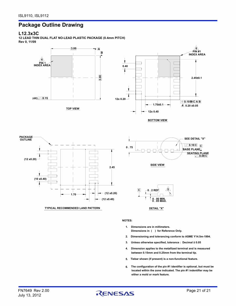
Package Outline Drawing
L12.3x3C12 LEAD THIN DUAL FLAT NO-LEAD PLASTIC PACKAGE (0.4mm PITCH)Rev 0, 11/09
located within the zone indicated. The pin #1 indentifier may be
Unless otherwise specified, tolerance : Decimal ± 0.05
Tiebar shown (if present) is a non-functional feature.
The configuration of the pin #1 identifier is optional, but must be
between 0.15mm and 0.25mm from the terminal tip.
Dimension applies to the metallized terminal and is measured
Dimensions in ( ) for Reference Only.
Dimensioning and tolerancing conform to ASME Y14.5m-1994.
6.
either a mold or mark feature.
3.
5.
4.
2.
Dimensions are in millimeters.1.
NOTES:
BOTTOM VIEW
DETAIL "X"
SIDE VIEW
TYPICAL RECOMMENDED LAND PATTERN
TOP VIEW
2.45±0.1
1.70±0.1
12x 0.40
12x 0.20
0.40
1.70
(10 x0.40)
(12 x0.20)
(12 x0.20)
(12 x0.40)
2.45
(4X) 0.15
INDEX AREAPIN 1
A3.00
B
3.0
0
PIN #1
B0.10 M AC
4
0 . 75 C
SEATING PLANE
BASE PLANE
0.08
0.10
SEE DETAIL "X"
C
C
0 . 00 MIN.0 . 05 MAX.
0 . 2 REFC 5
6
6
0.20 ±0.05
PACKAGE OUTLINE
INDEX AREA