iso 15590-1 e - cngspw.com€¦ · iso 3183-1, petroleum and natural gas industries — steel pipe...
TRANSCRIPT

Reference numberISO 15590-1:2001(E)
© ISO 2001
INTERNATIONALSTANDARD
ISO15590-1
First edition2001-06-01
Petroleum and natural gas industries —Induction bends, fittings and flanges forpipeline transportation systems —
Part 1:Induction bends
Industries du pétrole et du gaz naturel — Coudes d'induction, raccords etbrides pour systèmes de transport par conduites —
Partie 1: Coudes d'induction
ral gas industriegas industrfittings and flangs and flan
ortation systemsn system
bendsnds
du pétrole et du gaz natudu pétrole et du gaz natuour systèmes de transpor systèmes de transp
tie 1: Coudes d'inductionoudes d'inductio
oooomomom

ISO 15590-1:2001(E)
PDF disclaimer
This PDF file may contain embedded typefaces. In accordance with Adobe's licensing policy, this file may be printed or viewed but shall notbe edited unless the typefaces which are embedded are licensed to and installed on the computer performing the editing. In downloading thisfile, parties accept therein the responsibility of not infringing Adobe's licensing policy. The ISO Central Secretariat accepts no liability in thisarea.
Adobe is a trademark of Adobe Systems Incorporated.
Details of the software products used to create this PDF file can be found in the General Info relative to the file; the PDF-creation parameterswere optimized for printing. Every care has been taken to ensure that the file is suitable for use by ISO member bodies. In the unlikely eventthat a problem relating to it is found, please inform the Central Secretariat at the address given below.
© ISO 2001
All rights reserved. Unless otherwise specified, no part of this publication may be reproduced or utilized in any form or by any means, electronicor mechanical, including photocopying and microfilm, without permission in writing from either ISO at the address below or ISO's member bodyin the country of the requester.
ISO copyright officeCase postale 56 � CH-1211 Geneva 20Tel. + 41 22 749 01 11Fax + 41 22 749 09 47E-mail [email protected] www.iso.ch
Printed in Switzerland
ii © ISO 2001 – All rights reserved
m
ISO 15590-1:2001(E)
© ISO 2001 – All rights reserved iii
Contents Page
Foreword.....................................................................................................................................................................ivIntroduction .................................................................................................................................................................v1 Scope ..............................................................................................................................................................12 Normative references ....................................................................................................................................13 Terms and definitions ...................................................................................................................................34 Symbols and abbreviated terms ..................................................................................................................45 Designation ....................................................................................................................................................46 Pressure rating and design ..........................................................................................................................57 Information to be supplied by the purchaser .............................................................................................57.1 Principal information .............................................................................................................................57.2 Supplementary information ..................................................................................................................57.3 Information on the mother pipe............................................................................................................68 Manufacturing ................................................................................................................................................78.1 Manufacturing procedure specification...............................................................................................78.2 Mother pipe.............................................................................................................................................88.3 MPS qualification ...................................................................................................................................88.4 Production bending ...............................................................................................................................88.5 Post-bending heat treatment ................................................................................................................88.6 Forming and sizing after bending ........................................................................................................98.7 Strip/plate end welds .............................................................................................................................98.8 Jointers and girth welds........................................................................................................................98.9 End preparation......................................................................................................................................99 Testing and inspection................................................................................................................................109.1 General requirements ..........................................................................................................................109.2 Extent of testing and inspection.........................................................................................................109.3 Chemical composition.........................................................................................................................109.4 Physical testing....................................................................................................................................109.5 Non-destructive testing .......................................................................................................................179.6 Dimensions ...........................................................................................................................................199.7 Gauging.................................................................................................................................................229.8 Hydrostatic testing...............................................................................................................................2210 Inspection document...................................................................................................................................2211 Marking .........................................................................................................................................................22
bzfxw
.com
.................................
..................................................................................................
.................................................... ..............................................................................
............................................................ ...............................................................................
.......................................................................................................................................
.................................................................................................................................
.....................................................................................................................................
.......................................................................................................................................
.....................................................................................................................................................
.........................................................................................................................................................
..........................................................................................................................................
......................................................................nspection.......................tion.....................
ion...................................n..........................................................................................................
w.be testing ...................................................................................................................
...................................................................tatic testing....................sting...................
wwwn document....................ument..............g ....................................................................

ISO 15590-1:2001(E)
iv © ISO 2001 – All rights reserved
Foreword
ISO (the International Organization for Standardization) is a worldwide federation of national standards bodies (ISOmember bodies). The work of preparing International Standards is normally carried out through ISO technicalcommittees. Each member body interested in a subject for which a technical committee has been established hasthe right to be represented on that committee. International organizations, governmental and non-governmental, inliaison with ISO, also take part in the work. ISO collaborates closely with the International ElectrotechnicalCommission (IEC) on all matters of electrotechnical standardization.
International Standards are drafted in accordance with the rules given in the ISO/IEC Directives, Part 3.
Draft International Standards adopted by the technical committees are circulated to the member bodies for voting.Publication as an International Standard requires approval by at least 75 % of the member bodies casting a vote.
Attention is drawn to the possibility that some of the elements of this part of ISO 15590 may be the subject ofpatent rights. ISO shall not be held responsible for identifying any or all such patent rights.
International Standard ISO 15590-1 was prepared by Technical Committee ISO/TC 67, Materials, equipment andoffshore structures for petroleum and natural gas industries, Subcommittee SC 2, Pipeline transportation systems.
ISO 15590 consists of the following parts, under the general title Petroleum and natural gas industries — Inductionbends, fittings and flanges for pipeline transportation systems:
� Part 1: Induction bends
� Part 2: Fittings
� Part 3: Flanges
www.bzfx
w.comIS
n establion-governmevernme
tional Electrotechnl Electrotechn
Directives, Part 3.tives, Part 3
ed to the member bodiesmember bodiesf the member bodies casmember bodies ca
s part of ISO 15590 mayISO 15590 mall such patent rights.h patent rights.
al Committee ISO/TC 67mittee ISO/TC 6Subcommittee SC 2,mittee SC 2, Pipe
neral titletle Petroleum andPetroleum asystemssystems::

ISO 15590-1:2001(E)
© ISO 2001 – All rights reserved v
Introduction
Users of this part of ISO 15590 should be aware that further or differing requirements may be needed for individualapplications. This part of ISO 15590 is not intended to inhibit a manufacturer from offering, or the purchaser fromaccepting, alternative equipment or engineering solutions for the individual application. This can be particularlyapplicable where there is innovative or developing technology. Where an alternative is offered, the manufacturershould identify any variations from this part of ISO 15590 and provide details.
www.bzfx
w.com
e pcan be
ered, the manthe man

www.bzfx
w.com

INTERNATIONAL STANDARD ISO 15590-1:2001(E)
© ISO 2001 – All rights reserved 1
Petroleum and natural gas industries — Induction bends, fittingsand flanges for pipeline transportation systems —
Part 1:Induction bends
1 Scope
This part of ISO 15590 specifies the technical delivery conditions for bends made by the induction bending processfor use in pipeline transportation systems for the petroleum and natural gas industries as defined in ISO 13623.
This part of ISO 15590 is applicable to induction bends made from seamless and welded pipe of unalloyed or low-alloy steels.
This part of ISO 15590 specifies three classes of induction bend corresponding to increasing quality requirementsin accordance with the technical delivery conditions of ISO 3183 for pipe as indicated in Table 1 (see alsoISO 3183-3:1999, Introduction).
Table 1 — Induction bend class and corresponding pipe standard
Induction bend class Corresponding pipe standard
Class A ISO 3183-1
Class B ISO 3183-2
Class C ISO 3183-3
This part of ISO 15590 is not applicable to the selection of the induction bend class.
This part of ISO 15590 is not applicable to pipeline bends made by other manufacturing processes.
2 Normative references
The following normative documents contain provisions which, through reference in this text, constitute provisions ofthis part of ISO 15590. For dated references, subsequent amendments to, or revisions of, any of these publicationsdo not apply. However, parties to agreements based on this International Standard are encouraged to investigatethe possibility of applying the most recent editions of the normative documents indicated below. For undatedreferences, the latest edition of the normative document referred to applies. Members of ISO and IEC maintainregisters of currently valid International Standards.
ISO 148, Steel — Charpy impact test (V-notch).
ISO 377, Steel and steel products — Location and preparation of samples and test pieces for mechanical testing.
ISO 783, Metallic materials — Tensile testing at elevated temperature.
ISO 2566-1, Steel — Conversion of elongation values — Part 1: Carbon and low alloy steels.
www.bzfx
w.com
ends made by the inductiade by the inductiral gas industries as definustries as de
from seamless and weldeamless and w
ction bend correspondingend correspondinns of ISO 3183 for pipns of ISO 3183 for p
n bend class and corresd class and corre
bend class Coclass CzfzfzfzfzfClass AClass A bzzzzzClass Bass B bzClass CC bw
b590 is not applicable to thot applicable to th
O 15590 is not applicable0 is not applic
ormative referenceative reference
The following normative dlowing normhis part of ISO 15590part of ISO 1559
not apply. Howenot apply. Howeossibility ofsibility o
es, the

ISO 15590-1:2001(E)
2 © ISO 2001 – All rights reserved
ISO 3183-1, Petroleum and natural gas industries — Steel pipe for pipelines — Technical delivery conditions —Part 1: Pipes of requirement class A.
ISO 3183-2, Petroleum and natural gas industries — Steel pipe for pipelines — Technical delivery conditions —Part 2: Pipes of requirement class B.
ISO 3183-3:1999, Petroleum and natural gas industries — Steel pipe for pipelines — Technical deliveryconditions — Part 3: Pipes of requirement class C.
ISO 6507-1, Metallic materials — Vickers hardness test — Part 1: Test method.
ISO 6892, Metallic materials — Tensile testing at ambient temperature.
ISO 7438, Metallic materials — Bend test.
ISO/TR 7705:1991, Guidelines for specifying Charpy V-notch impact prescriptions in steel specifications.
ISO 8501-1, Preparation of steel substrates before application of paints and related products — Visual assessmentof surface cleanliness — Part 1: Rust grades and preparation grades of uncoated steel substrates and of steelsubstrates after overall removal of previous coatings.
ISO 9305, Seamless steel tubes for pressure purposes — Full peripheral ultrasonic testing for the detection oftransverse imperfections.
ISO 9712, Non-destructive testing — Qualification and certification of personnel.
ISO 10124, Seamless and welded (except submerged arc-welded) steel tubes for pressure purposes — Ultrasonictesting for the detection of laminar imperfections.
ISO 10474, Steel and steel products — Inspection documents.
ISO 11496, Seamless and welded steel tubes for pressure purposes — Ultrasonic testing of tube ends for thedetection of laminar imperfections.
ISO 12094, Welded steel tubes for pressure purposes — Ultrasonic testing for the detection of laminarimperfections in strips/plates used in the manufacture of welded tubes.
ISO 12095, Seamless and welded steel tubes for pressure purposes — Liquid penetrant testing.
ISO 13623, Petroleum and natural gas industries — Pipeline transportation systems.
ISO 13664, Seamless and welded steel tubes for pressure purposes — Magnetic particle inspection of the tubeends for the detection of laminar imperfections.
ISO 13665, Seamless and welded steel tubes for pressure purposes — Magnetic particle inspection of the tubebody for the detection of surface imperfections.
ASTM E 112, Standard test methods for determining average grain size.
ASTM E 340, Standard test method for macroetching metals and alloys.
ASTM E 797, Standard practice for measuring thickness by manual ultrasonic pulse-echo contact method.
European Federation of Corrosion, Publication No. 16:1995, Guidelines on materials requirements for carbon andlow alloy steels for H2S containing environments in oil and gas production.
w.bzfx
w.coms in steel specificationsel specifications
related productsed products —— VisuVisuof uncoated steel substrated steel substr
l peripheral ultrasonic teseral ultrasoni
rtification of personneltion of personnel.
ed arc-welded) steel tubed arc-welded) steel tub
ection documentsdocuments..
eel tubes for pressure pbes for pressure p
bes for pressure purporessure purps used in the manufacturein the manufacture
wwwand welded steel tubes folded steel tubes fo
leum and natural gas indnd natural gas ind
Seamless and welded sss and weldhe detection of laminar imtection of laminar
13665, Seamless and wSeamless and wdy for the detection of suhe detection
E 112,112, StandaStan
St

ISO 15590-1:2001(E)
© ISO 2001 – All rights reserved 3
3 Terms and definitions
For the purposes of this part of ISO 15590, the following terms and definitions apply.
3.1arccurved portion of a bend
3.2bend angleamount of directional change through the bend
3.3bend radiusdistance from the centre of curvature to the centreline axis of the bent pipe
3.4by agreementagreed between manufacturer and purchaser
3.5extradosouter curved section of the bend arc
3.6heatbatch of steel prepared in one steel-making operation
3.7induction bendingcontinuous bending process which utilizes induction heating to create a narrow, circumferential, heated bandaround the material being bent
3.8intradosinner curved section of the bend arc
3.9manufacturing procedure specificationMPSdocument which specifies the properties and description of the mother pipe, the bending procedure, the post-bending heat treatment equipment and cycle, the qualification bend testing results, the non-destructive testingprocedures and the weld end bevel details used for the manufacture of the bends
3.10mother pipestraight section of pipe from which an induction bend is made
3.11tangentstraight section at the ends of an induction bend
3.12transition zoneareas at the start and stop points of bending which include material that extends from the unheated mother pipe tothe material that has been heated to the full bending temperature
www.bzfx
w.com
tionion
tilizes induction heatinginduction heating
bend arcarc
rocedure specificationure specificatio
hich specifies the propespecifies the propeat treatment equipmenatment equ
ures and the weld end bend the weld end b
10mother pipepipewtraight section of pipaight section of pi

ISO 15590-1:2001(E)
4 © ISO 2001 – All rights reserved
3.13wall thinningamount of reduction from the original wall thickness of the pipe to the wall thickness in the extrados after bending
4 Symbols and abbreviated terms
For the purpose of this part of ISO 15590, the following symbols and abbreviations apply.
A Percentage of elongation of tensile test specimen after fracture
CE Carbon equivalent
CTOD Crack tip opening displacement testing
D Specified diameter (outside or inside)
Dmax Maximum measured diameter (outside or inside)
Dmin Minimum measured diameter (outside or inside)
DWT Drop-weight tear testing
HAZ Heat-affected zone
HIC Hydrogen-induced cracking
HFW High-frequency welded
MT Magnetic particle testing
NDT Non-destructive testing
PT Liquid penetrant testing
R Bend centreline radius
r Mean radius of the mother pipe
Rm Ultimate tensile strength
R t 0,5 Yield strength for 0,5 % total elongation
RT Radiographic testing
SAW Submerged arc welding
SAWH Helical seam SAW pipe
So Initial cross-sectional area of the gauge length of a tensile test specimen
SSC Sulfide stress-cracking
Td min Minimum design temperature specified by the purchaser
t i Minimum wall thickness at the bend intrados
tmin Minimum wall thickness required in accordance with ISO 13623 for the straight pipe adjacent to thebend
UT Ultrasonic testing
WPS Welding procedure specification
5 Designation
Designation of induction bends shall take the form IB xxx-A or B or C or CS, where:
� xxx is the specified minimum yield strength, expressed in megapascals;
� the suffix A, B, C identifies the technical delivery conditions class for induction bends in non-sour service;
� the suffix CS identifies class C bends for use in sour-service conditions.
ww.bzfx
w.com
tal elongationtal elongatio
lding
AW pipepe
-sectional area of the gaunal area of the ga
stress-cracking-cracking
imum design temperatureesign temperat
inimum wall thickness am wall thickness a
wwMinimum wall thickneinimum wall thicknbendend
Ultrasonic testinUltrasonic testi
S Welding proWelding prwignatioatio
ISO 15590-1:2001(E)
© ISO 2001 – All rights reserved 5
6 Pressure rating and design
The hoop stress in the induction bend due to internal fluid pressure shall not exceed the hoop stress permitted inISO 13623 for the adjacent straight pipe.
Compliance with this requirement shall be demonstrated either by calculations or by satisfying both of the followingrequirements.
a) The wall thickness of the bend extrados shall be at least tmin.
b) The wall thickness at the bend intrados shall be at least:
i min2
2( )R r
t tR r
�
�
�
�
For pipelines not designed in accordance with ISO 13623, it may be permitted for the wall thickness of the bendextrados to be less than tmin.
The requirements in this clause address the design of a bend against internal pressure. Other loads, both staticand dynamic, and pipeline test conditions also need to be considered by the designer to demonstrate compliancewith the strength requirements of ISO 13623.
7 Information to be supplied by the purchaser
7.1 Principal information
The purchaser shall provide the following information, in the order given below:
a) bend designation of each bend;
b) quantity of bends;
c) supply of mother pipe by the purchaser or the manufacturer;
d) required bend dimensions, including:
1) diameter (inside or outside),
2) minimum wall thickness,
3) radius,
4) bend angle,
5) tangent lengths;
e) end preparation if different from square ends.
7.2 Supplementary information
If applicable, the purchaser should specify the following supplementary information:
a) minimum design temperature;
b) maximum design temperature;
ww.bzfx
w.comitted for the wall thicknesthe wall thicknes
inst internal pressure. Oal pressure.ered by the designer toby the designer to
haser
nformation, in the order gation, in the order
by the purchaser or the mpurchaser or the m
ensions, including:ns, includin
wwwer (inside or outside),ide or outside),
inimum wall thickness,wall thickness,
) radius,dius,
4) bend angle,bend anglw5) tangent len5) tangent len
prepa

ISO 15590-1:2001(E)
6 © ISO 2001 – All rights reserved
c) maximum wall thickness;
d) special dimensional requirements;
e) requirements for supplementary inspection and testing;
f) requirements for gauging and other measurements of dimensions if different from this part of ISO 15590;
g) pipeline design standard or design factors, if different from ISO 13623;
h) pipeline operating conditions;
i) whether post-bending heat treatment is to be applied;
j) mechanical property requirements at the maximum design temperature;
k) requirements for proof, burst or hydrostatic testing;
l) hold-points for witness and approval by purchaser;
m) surface condition;
n) coating or painting requirements;
o) marking requirements if different from this part of ISO 15590;
p) packaging and shipping instructions;
q) third-party inspection organization;
r) standard designation in accordance with ISO 10474 of inspection document required;
s) requirements for format and additional content of the inspection document.
7.3 Information on the mother pipe
If the mother pipe is supplied by the purchaser, the following information on the mother pipe shall be provided tothe manufacturer:
a) purchasing specification;
b) pipe diameter (inside or outside);
c) pipe wall thickness (nominal or minimum);
d) pipe lengths;
e) pipe manufacturer;
f) inspection documents with complete chemical composition, mechanical properties, results of NDT anddimensions;
g) welding procedure specification and weld metal chemical composition for SAW and SAWH pipe;
h) weld seam repair welding procedure specification for SAW and SAWH pipe.
ww.bzfx
w.com
15590;0;
with ISO 10474 of inspectO 10474 of inspec
ditional content of the inspional content of the ins
mother pipeer
pplied by the purchaser,by the purchaser
specification;ation;
wwiameter (inside or outsideer (inside or outs
ipe wall thickness (nominthickness (nom
pipe lengths;ipe lengths;
manufactuanufact

ISO 15590-1:2001(E)
© ISO 2001 – All rights reserved 7
8 Manufacturing
8.1 Manufacturing procedure specification
Test bends shall be manufactured in accordance with a preliminary MPS documented before commencement oftest bending. The preliminary MPS shall be modified as necessary, based on the parameters recorded during testbending, prior to commencing production bending. If specified by the purchaser, manufacturing shall not proceeduntil the MPS has been accepted by the purchaser.
The MPS shall specify the following details.
a) Information on the mother pipe:
1) name of manufacturer;
2) steel class and name;
3) pipe forming process;
4) pipe dimensions;
5) chemical composition;
6) mechanical properties;
7) welding procedure and weld metal chemical composition for welded pipe;
8) inspection technique and reports for weld seam;
9) weld seam repair procedures;
10) heat treatment conditions.
b) Testing and inspection requirements for:
1) qualification test bend;
2) production bends.
c) Bending process details:
1) pipe cleaning method prior to bending;
2) identification of the bending machine;
3) method of temperature measurement and control during bending;
4) values of bending parameters (see Table 2);
5) heating and quenching of tangent ends.
d) Details of post-bending heat treatment:
1) type of post-bending heat treatment;
2) heating rate, soaking time and temperature, cooling rate;
3) type and location of thermocouples.
www.bzfx
w.com
cal composition for weldeal composition for welde
weld seam;seam;
quirements for:nts for:
st bend;
n bends.ds.
process details:details:
pipe cleaning method prcleaning method
ww2) identification of theidentification of th
3) method of tem3) method of tw) values ovalues

ISO 15590-1:2001(E)
8 © ISO 2001 – All rights reserved
e) Sizing and rounding processes.
f) Additional purchaser requirements (such as end preparation, coating and marking).
8.2 Mother pipe
The mother pipe may be supplied by either the purchaser or the manufacturer.
If the mother pipe is supplied by the purchaser, the manufacturer should be consulted as to the required chemicalcomposition, properties and dimensions of the mother pipe (including seam weld and seam repair weld) regardingsuitability for induction bending.
Permissible welding processes for the mother pipe shall be as allowed in the corresponding part of ISO 3183. Themother pipe should not contain weld repairs to the pipe body.
The wall thickness of the mother pipe shall have adequate allowance for wall thinning at the extrados due toinduction bending.
The surface of the mother pipe shall be free of contamination by low-melting temperature metals, such as copper,brass and aluminium.
8.3 MPS qualification
Bend manufacture shall be carried out in accordance with an MPS which shall be qualified in accordance with thisclause before commencement of production.
A test bend with a sufficient arc length to allow extraction of the necessary test specimens shall be manufactured inaccordance with each preliminary MPS. The inspection and testing of the test bend shall include tangents andtransition zones if included in the produced bends.
The test bend shall be tested and inspected in accordance with clause 9.
The MPS to be used for production shall, for each of the essential variables in Table 2, specify:
� the values recorded during the manufacturing of the test bend;
� the permissible range during production bending.
The variation in essential variables shall not exceed the permissible limits shown in Table 2.
8.4 Production bending
Induction bending shall be carried out in accordance with a qualified MPS as specified in 8.3.
Interruption of the induction bending operation shall result in rejection of the bend.
8.5 Post-bending heat treatment
Post-bending heat treatment of bends is not mandatory for compliance with this part of ISO 15590.
Post-bending heat treatment may be performed to achieve the required material properties, improve corrosionresistance, remove transition zones at the ends of the bend arc or to relieve residual stresses.
The temperature of each furnace-load of bends shall be monitored by thermocouples connected directly to selectedbends and shall be recorded. The type and location of the thermocouples shall be as specified in the MPS.
www.bzfx
w.com
equiredair weld) reeld) re
ding part of ISO 3183. Tart of ISO 3183. T
all thinning at the extrading at the extrad
elting temperature metalsperature me
an MPS which shall bePS which shall be
traction of the necessarytion of the necessaryinspection and testing oftion and testing
ends.
cted in accordance with cccordance with
n shall, for each of the esall, for each of the es
ng the manufacturing of thmanufacturing of t
ge during production bening production ben
sential variables shall nol variables shall no
uction bendingbending
wwion bending shall be carriding shall be c
erruption of the inductioption of the induwost-bendint-bend

ISO 15590-1:2001(E)
© ISO 2001 – All rights reserved 9
8.6 Forming and sizing after bending
Hot forming, including spot heating, or hot sizing after bending, shall not be performed unless followed by asubsequent full heat treatment above the upper critical temperature.
Cold forming or sizing without subsequent heat treatment is permitted provided the induced permanent strain doesnot exceed 1,5 %.
Table 2 — Essential variables and maximum permissible variations
Essential variable Maximum permissible variations
Heat of steel None
Mother pipe seam weld WPS and welding consumables None
Nominal mother pipe diameter None
Nominal mother pipe wall thickness � 3 mm
Bend radiusFor R u 5D : � �25
0 %
For 5D � R u 10D : � �1000 %
For R � 10D : � �unlimited0
Forming velocity � 2,5 mm/min
Forming temperature � 25 �C
Coil design None
Coolant None
Coolant flowrate or pressure � 10 %
Coolant temperature � 15 �C
Induction heating frequency � 20 %
Weld seam location � 15� from the location in the test bend
Post-bending heat treatment Method: no change
Soaking time: � �150 min
Soaking temperature: � 15 oC
Heating and cooling rates: by agreement
The permissible variations apply to the values as stated in the MPS.
8.7 Strip/plate end welds
Induction bends shall not contain strip/plate end welds.
8.8 Jointers and girth welds
Induction bends shall not contain girth welds.
8.9 End preparation
Bends shall be supplied with square ends unless otherwise specified by the purchaser.
fxw.co
mriationsns
mmmom�0 %
� R u 1010D : � ��100100
www.bzfx
w.com
0 %%
For R � 1010DD :: � �� �unlimitedunlimited
www.bzfx
w.com
00
www.bzfx
w.com
co
zfxw� 2,5 mm/min2,5 mm/minwfx
�� 2525 �CC
fxfxfxwfxfxzfxNoneone
bzfxfxfxzfxNoneNonezfxzfxzfxzfx
w.bzf�bzfzfzfzfbzbzb
www.t treatmentent
w.The permissible variationpermissible variatio
wwwww7 Strip/plate eStrip/plate e
n bend

ISO 15590-1:2001(E)
10 © ISO 2001 – All rights reserved
9 Testing and inspection
9.1 General requirements
An MPS shall be approved or production bends accepted only after all testing and inspection required in this clausehave been performed and all results meet the specified requirements.
Except where otherwise stated in this clause, the testing and inspection methods and acceptance criteria forinduction bends shall be as required by the corresponding part of ISO 3183 for pipe of the same steel grade andtype.
Testing and inspection shall be carried out on bends after final heat treatment.
Test results already available for the mother pipe may be used in place of re-testing where indicated in Table 3.
If the pipeline installation techniques require post-weld heat treatment of the bend, the purchaser may requireadditional testing to demonstrate that the mechanical properties of the bend are also achieved after post-weld heattreatment. The purchaser shall specify the details of the post-weld heat treatment cycle to be used during pipelineinstallation. The test requirements and acceptance criteria shall be decided by agreement.
9.2 Extent of testing and inspection
9.2.1 MPS qualification test bend
The extent of testing and inspection to be performed for qualification of the MPS shall be as stated in Table 3 foreach bend class.
The location and type of tests shall be as specified in Table 4, with the locations for the extraction of samples asshown in Figure 1. For SAWH pipe, the inspection and testing requirements shall be decided by agreement.
9.2.2 Production bends
The extent of testing and inspection to be performed during production shall be as stated in Table 3 for each bendclass.
9.3 Chemical composition
The chemical composition of each bend shall comply with the requirements for pipe of the same grade and type asspecified in the corresponding part of ISO 3183.
NOTE In some instances, aluminium and/or copper contents within the limits allowed by ISO 3183 can give rise toembrittlement and cracking during bending.
9.4 Physical testing
9.4.1 Test pieces — General
Test pieces shall be prepared in accordance with ISO 377.
If thermal cutting has been used to remove samples, the full extent of the heat-affected region shall be removedduring the preparation of the test pieces.
9.4.2 Tensile testing
9.4.2.1 Test pieces
Round bar test pieces machined from unflattened samples may be used by agreement.
Welds shall be ground flush. Local imperfections and mill scale may be removed.
www.bzfx
w.com
steel
here indicated in Table 3.icated in Table
bend, the purchaser mathe purchaser mre also achieved after pohieved after
atment cycle to be usedt cycle to be usedd by agreement.reem
qualification of the MPSfication of the MPS
ed in Table 4, with the loin Table 4, with the lion and testing requiremed testing require
to be performed duringo be performed during
ition
ition of each bend shall cach bend shallresponding part of ISO 31nding part of ISO 3
some instances, aluminiuminstances, aluminiumt and cracking during bendiking during b
Physical testingal testing
.1 Test piecesTest pieces —— Gwces shall bees shall b
ttin

ISO 15590-1:2001(E)
© ISO 2001 – All rights reserved 11
Table 3 — Summary of testing and inspection requirements
Test Class A Class B Class C Acceptance
Chemical analysis Chemical composition M M M ISO 3183
Physical tests Tensile T T T ISO 3183
Impact O T T 9.4.3.3
Through-thicknesshardness
N T T 9.4.4.2
Surface hardness T and P T and P T and P 9.4.5.2
Metallography T T T 9.4.6.2
HIC N N Oa 9.4.7
SSC N N Oa 9.4.8
DWT N N O By agreement
CTOD N N O By agreement
Guided bend (weld seam) M M M ISO 3183
Flattening M M M ISO 3183
NDT Visual inspection T and P T and P T and P ISO 3183 and 9.5.1
Weld seam (UT or RT) M M T and P ISO 3183
Bend ends (laminations) P P P 9.5.3
Bend body (MT or PT) T and P T and P T and P 9.5.4
Bend body (UT)transverse defects
N T and O T and P 9.5.5
Bend body (UT)laminations
N M M 9.5.5
Residual magnetism ends P P P 9.5.6
Repairs P P P ISO 3183
Dimensions Wall thickness T and P T and P T and P 9.6
D bend body P P P 9.6
D at ends P P P 9.6
Out-of-roundness ends P P P 9.6
Out-of-roundness body P P P 9.6
Linear dimensions P P P 9.6
Angle P P P 9.6
Radius O O O 9.6
End squareness P P P 9.6
Out of plane P P P 9.6
End preparation By agreement By agreement
Gauging By agreement By agreement
Hydrostatic test By agreement By agreement
a Only required for sour-service conditions.
M – Testing of the induction bend shall not be required if acceptable test results are available for the mother pipe. If acceptable test resultsfor the mother pipe are not available then the test shall be performed on either the mother pipe or the bend.
N – Not required.
O – Performance of the test or inspection on a production induction bend may be required by agreement.
P – Required for each production bend.
T – Required for each MPS qualification test bend.
www.bzfx
w.com
.4.5.2
9.4.6.2
m9.4.7.4.7mOa 9.4.89.4.8moO By agreemeBy agreemooomoO By agreeO By agooomcoM ISOM ISOcccooocoM M IMcccooocoT and P T and Pnd P T and Pcccw
cM T andM T
wc
wc
wc
wwc
PPwwwww.wwand P T and PT and PwwwwwxwwN T and OT and OxwxwxwxwNN fxwxwxwz xwm ends Ps Pzzzfxxxbzx
PP
bzbzbzf
bzess T andss T andbzbzbzbzbody bzbzbzbzt ends bbbbOut-of-roundness endsoundness ends
wb
Out-of-roundness bodyt-of-roundness bodw.Linear dimensionsLinear dimensionwwAngleAngle
wwwwRadiusRadiwwwwEnd squEnd sqwwwOutOwwwwwwwwGaugingauging wrostatic teststatic testwwquirew

ISO 15590-1:2001(E)
12 © ISO 2001 – All rights reserved
Table 4 — Location of test pieces and type of test for destructive testing of test bends
Location Test
Tangent base metal a Tensile
Impact
Through-thickness hardness
Tangent weld a Tensile transverse
Impact
Flattening
Through-thickness hardness
Metallography
Guided bend
Transition zones base metal Tensile
Impact
Through-thickness hardness
Metallography
Transition zones weld Tensile transverse c
Impact c
Bend extrados base metal Tensile
Impact
Through-thickness hardness
Bend intrados base metal Tensile
Impact
Through-thickness hardness
Bend weld b Tensile transverse
Impact
Through-thickness hardness
Metallography
Guided bend
a Testing after bending is not necessary if test results are available for mother pipe and thetangent is not heat-treated during induction bending or subsequent heat treatment.b Additional testing for SAWH pipe shall be by agreement.c These tests may be distributed between the two transition zones.
9.4.2.2 Test method
Tensile testing at ambient temperature shall be carried out in accordance with ISO 6892. Additional elevatedtemperature tensile testing should be performed if the maximum design temperature exceeds 50 °C. Tensile testingat elevated temperatures shall be carried out in accordance with ISO 783 and the acceptance criteria shall be byagreement.
Rm, R t 0,5 and A shall be determined using test pieces from the base metal in the bend arc and tangent.
bzfxw
.commmmmm
cokness hardnesshard
raphy
ile transversensverse ccwImpactImp c
TensileTensile fxwfImpactImpact
zfThrough-thickThrough-thi
bzf
etal
bzf
bzf
TensileTensile
www.bbzfbzf
bzf
ImpaImpabzTbb baa Testing aftTestingtangent is notangent is nbb AddAcwwwwww

ISO 15590-1:2001(E)
© ISO 2001 – All rights reserved 13
The percentage elongation after fracture shall be reported with reference to a gauge length of 05,65 S . If other
gauge lengths are used, the elongation referred to a gauge length of 05,65 S shall be determined in accordancewith ISO 2566-1.
For weld transverse tensile tests, Rm only shall be required.
Key
1 Tangent weld
2 Transition zone base metal
3 Bend extrados base metal
4 Bend weld
5 Transition zone weld
6 Bend intrados base metal
7 Tangent base metal
Figure 1 — Location for extraction of samples for testingwww.bzfx
w.com
cw
c
bbbw.cow.co
xwco
m
wxwwxwco
mom
wcoo
mmomomomcoocowww
bzfxw
.com
cww.c
ne base metalse metal
rados base metalmeta
weld
ansition zone weldn zone weld
wwBend intrados base metaltrados base me
7 Tangent base metalgent base m

ISO 15590-1:2001(E)
14 © ISO 2001 – All rights reserved
Dimensions in millimetres
Key
1 Weld centreline
2 Fusion line
3 Fusion line � 2 mm
4 Fusion line � 5mm
Figure 2 — Location of V-notch test pieces in the weld region of SAW pipe
9.4.3 Charpy V-notch impact testing
9.4.3.1 Test pieces
Charpy V-notch test pieces shall be prepared in accordance with ISO 148 with the axis of the notch perpendicularto the bend surface. Alternative test pieces may be used by agreement (see ISO 3183-3:1999, 8.2.24). Theorientation and size of the test pieces shall be transverse with the greatest possible width between 10 mm and5 mm. If transverse test pieces with a minimum width of 5 mm are not possible, longitudinal test pieces with thegreatest possible width between 10 mm and 5 mm shall be used.
Impact testing is not required if the bend dimensions are insufficient to produce longitudinal test pieces with aminimum width of 5 mm.
All Charpy V-notch test pieces shall be taken from the sample at a depth of no more than 2 mm below the outersurface.
Test pieces from welds in SAW pipe with a wall thickness not exceeding 25 mm shall be taken across the weld withthe notch at the four locations indicated in Figure 2. The distance of notch location from the fusion line shall bedetermined with reference to the centreline of the test piece.
Test pieces from welds in HFW pipe shall be taken across the weld: one set with the notch located in the weldcentreline and one set with the notch located 2 mm from the weld centreline. The weld centreline shall be locatedby using metallographic etching techniques.
For bends with a wall thickness greater than 25 mm, the locations of test pieces shall be decided by agreement.
9.4.3.2 Test method
Each set of impact tests shall consist of three adjacent test pieces taken from a single non-flattened sample.
xw.co
momo
ww.bzfx
wst pieces in the weld regst pieces in the weld r
prepared in accordance wrepared in accordancetest pieces may be uset pieces may be use
pieces shall be transvershall be transes with a minimum widthth a minimum widt
ween 10 mm and 5 mm s0 mm and 5 mm
required if the bend dimif the bendmm.
wwwnotch test pieces shall btest pieces shall b
ieces from welds in SAWm welds in SAnotch at the four locatioat the four locatio
termined with referenceined with referewces from ws from wand on

ISO 15590-1:2001(E)
© ISO 2001 – All rights reserved 15
Charpy V-notch impact testing shall be in accordance with ISO 148 with an additional requirement to report sheararea of the fracture surface for all test pieces except those for the weld centreline.
The impact test temperature shall be established in accordance with Table 5.
Table 5 — Maximum Charpy V-notch test temperature
Nominal wall thicknessmother pipe
mm
Test temperature
°C
Class A Class B Class C
t u 20 By agreement Td min. Td min. – 10
20 � t u 25 By agreement Td min. Td min. – 20
t � 25 By agreement By agreement By agreement
9.4.3.3 Requirements
For bends from mother pipe with a nominal wall thickness up to and including 25 mm, the results of the CharpyV-notch impact tests shall meet the following requirements.
a) For each set of tests, the minimum average absorbed energy in joules shall be:
Specified Minimum Yield Strength (MPa),
10with a minimum of 27 J, for the transverse direction.
b) The minimum individual value for any set of tests shall not be less than 75 % of the minimum required averagevalue.
c) The minimum average and individual values when testing longitudinal test pieces shall be 1,5 times the valuesspecified for transverse test pieces.
d) The minimum average shear area at the fracture surface shall be 50 % and all individual test pieces shallexhibit at least 40 % fibrous shear.
For subsize test pieces, the minimum required absorbed energy values shall be adjusted in accordance withISO/TR 7705, clause 6.
Any additional requirements for assessing the resistance to brittle fracture in thicker wall induction bends and forthe arrest of shear fracture shall be by agreement.
NOTE Owing to the relatively small percentage of total pipeline length represented by bends, and their dimensionalconsiderations, shear fracture arrest principles are not normally applied to induction bends.
9.4.4 Through-thickness hardness testing
9.4.4.1 Test method
For class B and C bends, through-thickness hardness testing shall be performed using the Vickers method inaccordance with ISO 6507-1 with a test force of 98,07 N. Hardness indent locations shall be in accordance withISO 3183-3.
fxw.co
mmClass CC mmmTd min.Td min. –– 1010mmmTTd min.d mTd min.Td min.
www.bzfx
w.comT –– 2020ommment By agreemenBy agreemenocccco
up to and including 25 mand including 25
orbed energy in joules shorbed energy in joules
ww.bzfx
with a minimum of 27 Ja minimum of
any set of tests shall nott of tests shall not
d individual values whenidual values whentest pieces.
erage shear area at theshear area at th40 % fibrous shear.rous shear.
est pieces, the minimumces, the minim5, clause 6.use 6
wwdditional requirements foal requirements farrest of shear fracture sf shear fracture
NOTE Owing to theE Owing tonsiderations, shear frsiderations, shearwThrougug
ISO 15590-1:2001(E)
16 © ISO 2001 – All rights reserved
9.4.4.2 Requirements
Hardness readings shall not exceed
� 300 HV 10 for class B and C bends,
� 250 HV 10 for class C bends intended for sour-service conditions (designation CS).
9.4.5 Surface hardness testing
9.4.5.1 Test method
Three surface hardness readings shall be taken across two circumferential locations in the arc and across onecircumferential location in each tangent.
The same type of testing device shall be used for both test and production bends. The selection of the testingdevice shall be by agreement.
9.4.5.2 Requirements
The average value of the three readings at each location of the test bend fabricated for MPS qualification shall beused as the reference for production test acceptance.
The average value of the three hardness readings at each location of a production bend shall not vary by morethan the equivalent of 30 HV 10 hardness points from the average value measured in the same location of the testbend. Single hardness values shall meet the requirements of 9.4.4.2.
9.4.6 Metallographic examination
9.4.6.1 Test method
The test pieces for through-thickness hardness testing (see 9.4.4) shall be examined, prior to hardness testing, at amagnification of not less than 100 �. Test piece preparation shall be in accordance with ASTM E 340.
Photomicrographs of the microstructures of the test bend arc, transition and tangent materials after completion ofall post-bend heat treatment shall be prepared at magnifications of 100 � and 400 �. The photomicrographs shallbe representative of the full wall thickness and shall include the external surface of the extrados of the arc of thebend and the transition zones. Grain-size measurement shall be performed in accordance with ASTM E 112 whereappropriate for the microstructure.
9.4.6.2 Requirements
The photomicrographs shall demonstrate that the induction bending and any subsequent heat treatment haveproduced a consistent microstructure without separations in the base metal and, for welded pipe, in the weld andHAZ. The type of microstructure and actual grain size shall be recorded on the bending procedure qualification testreport. The minimum average grain-size number shall be 7.
9.4.7 Hydrogen-induced cracking testing
Unless otherwise specified in the purchase order, the test procedures and acceptance criteria shall be inaccordance with European Federation of Corrosion, Publication No. 16, Annex B.
9.4.8 Sulfide stress cracking testing
Unless otherwise specified in the purchase order, the test procedures and acceptance criteria shall be inaccordance with European Federation of Corrosion, Publication No. 16.
www.bzfx
w.comin the arc and across oarc and acro
bends. The selection ofhe selection of
test bend fabricated for Md fabricated
ch location of a productcation of a producthe average value measuthe average value mea
ments of 9.4.4.2.ents of 9.4.4.2.
ss hardness testing (seehardness testing (see�. Test piece preparatit piece prepar
icrostructures of the tesuctures of the tesment shall be prepared ashall be prepared
the full wall thickness anll wall thicknessition zones. Grain-size mzones. Grain-size m
the microstructure.structure.
wwRequirementsirements
photomicrographs shallmicrographs shalduced a consistent mica consisten. The type of microsThe type of microwThe minimumThe minimu
oge

ISO 15590-1:2001(E)
© ISO 2001 – All rights reserved 17
9.4.9 Drop-weight tear testing
DWT is not mandatory for any bend class.
Test methods, test piece locations and acceptance criteria shall be decided by agreement.
9.4.10 Crack tip opening displacement testing
CTOD testing is not mandatory for any bend class.
Test methods and requirements shall be decided by agreement.
9.4.11 Guided bend testing
9.4.11.1 Test pieces
Test pieces shall be taken in accordance with ISO 7438.
For induction bends with a wall thickness � 20 mm, the test pieces may be machined to provide a rectangular crosssection having a thickness of 19 mm. Full thickness curved section test pieces are mandatory for pipe wallthickness u 20 mm. Welds shall be ground flush at both faces.
9.4.11.2 Test method
The mandrel dimensions shall be as defined in the corresponding part of ISO 3183 for pipe of the same grade asthe production bend and made by the same process as the mother pipe.
Both test pieces shall be bent through approximately 180°, one with the root of the weld and the other with the faceof the weld directly under the mandrel.
9.4.12 Flattening tests
If required, flattening tests shall be as defined in the corresponding part of ISO 3183 for pipe of the same grade andtype.
9.5 Non-destructive testing
9.5.1 Visual inspection
Visual inspection for laminations, cracks, notches, gouges and other imperfections shall be performed on thecomplete outer and, if practical, the inner surface of the bend in accordance with ISO 3183-3:1999, 8.2.3.13. Priorto visual inspection, the entire outside surface of all bends shall be cleaned to a cleanliness grade of ISO 8501-1Sa 2.
Waving, as shown in Figure 3, is acceptable provided that the following requirements are met:
� wave shapes blend into the pipe surface in a gradual manner with a maximum crest-to-valley depth, CVD, of1 % of the actual outside diameter;
� the ratio of the distance between adjacent crests, l, to the CVD is a minimum of 25.
CVD shall be determined as follows:
2 432
D DCVD D
�� �
ay be machined to provichined to proection test pieces are mtest pieces are
corresponding part of IScorresponding part of Iess as the mother pipe.s as the mother pipe
ximately 180tely 180°°, one with, one wit
ll be as defined in the codefined in the co
tive testingesting
inspectiontion
pection for laminations,for laminate outer and, if practical,er and, if practica
sual inspection, the entirespection, the entir2.
aving, as shown inving, as shown inwve shapeshapof th

ISO 15590-1:2001(E)
18 © ISO 2001 – All rights reserved
where
D2 and D4 are the outside diameters of two adjacent crests;
D3 is the outside diameter of the intervening valley.
9.5.2 Weld seam testing
RT or UT of the weld seam shall be required for
� the complete weld seam in the arc and transition zones;
� the end 250 mm of the tangent, if not examined already on the mother pipe prior to bending.
9.5.3 Inspection of bend ends
After end preparation, the complete end preparation and 100 mm of the weld seam shall be inspected by MT or PT.MT of bend ends shall be performed in accordance with ISO 13664. PT shall be performed in accordance withISO 12095.
For class B and C bends, a 50 mm wide band at each end shall be inspected for laminar imperfections by UT inaccordance with ISO 11496. Laminar imperfections shall not exceed 6 mm in the circumferential direction or havean area in excess of 100 mm2.
9.5.4 Magnetic particle testing or liquid penetrant testing on bend body
For all bends, the bend body shall be inspected over an arc of 90° both sides from the extrados by MT inaccordance with ISO 13665 or PT in accordance with ISO 12095.
All cracks, laps, laminations, and all rounded indications greater than 3 mm in any direction, shall be classed asdefects and shall be repaired in accordance with 9.5.7.
9.5.5 Ultrasonic testing on bend body
If required, ultrasonic testing in accordance with ISO 9305 shall be performed on the bend extrados to verify thatthe bend is free from transverse defects.
If required, ultrasonic testing in accordance with ISO 12094, or ISO 10124 as appropriate, shall be performed onthe bend to detect laminar imperfections. The acceptance criteria shall be as stated in the appropriate part ofISO 3183.
9.5.6 Level of residual magnetism
The level of residual magnetism shall not exceed 2 mT.
9.5.7 Repairs
Unless otherwise agreed by the purchaser, no repair by welding shall be performed on any part of the bend ortangents. If repair by welding is agreed, weld repairs should be examined by UT and/or RT.
Surface defects may be removed by grinding, provided that a smooth curved surface is maintained and therequired minimum wall thickness is maintained. Thickness measurement by UT shall be in accordance withASTM E 797.
All ground repair areas shall be examined by MT in accordance with ISO 13665, or PT in accordance withISO 12095, to confirm the complete removal of the defects.
ww.bzfx
w.combending.g.
d seam shall be inspectedm shall be inspecteT shall be performed inbe performed in
ll be inspected for laminapected for laxceed 6 mm in the circu6 mm in the circu
t testing on bend bodyt testing on bend body
ted over an arc of 90ver an arc of 90°°ce with ISO 12095.h ISO 1209
nded indications greaterindications greaterdance with 9.5.7.ance with 9.5
end body
ng in accordance with ISccordance with ISsverse defects.e defects.
nic testing in accordancesting in accordanc
wwwect laminar imperfectioninar imperfect
Level of residual magneof residual magne
e level of residual magneof residual m
Repairsepairs
rwis

ISO 15590-1:2001(E)
© ISO 2001 – All rights reserved 19
Figure 3 — Schematic diagram for measurement of waving
9.5.8 NDT personnel
All NDT personnel shall be qualified and certified in accordance with ISO 9712 to the appropriate level ofcompetence.
9.6 Dimensions
The dimensions of the bends shall be measured to confirm that the dimensions specified by the purchaser havebeen achieved within the permissible tolerances of Table 6.
Wall thickness measurements shall be made at sufficient locations by ultrasonic methods in accordance withASTM E 797.
The bend angle may be determined as follows (see Figure 4).
a) Extend the centreline axis of each tangent to the “centre of bend” where the two axes cross.
b) Measure and mark the distance from the “centre of bend” to each of the "centre of ends".
c) Calculate the bend angle from the two “centre of bend” to “centre of end” dimensions and the chord length.
For angles less than 15°, the angle may be determined by measuring a triangle established by the two centrelineaxes and the offset at the end of the bend, as shown in Figure 4 b).
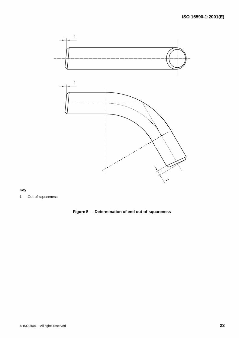
End out-of-squareness shall be measured from lines constructed at the specified bend angle and linesperpendicular to the plane of the bend, as shown in Figure 5.
Out-of-planeness is measured by levelling the centrelines of both bend tangents and measuring the difference inheight between the two tangent centrelines, as shown in Figure 6.
Out-of-roundness, expressed as a percent, is defined as: max min 100D D
D
�
�
w.commo
www.bzfx
wosurement of wavingof waving
accordance with ISO 9rdance with ISO
asured to confirm that thd to confirm thaterances of Table 6.s of Table 6.
ll be made at sufficientll be made at sufficien
termined as follows (see Follows (see
line axis of each tangentxis of each tangen
mark the distance fromthe distance from
te the bend angle from thbend angle from th
gles less than 15less than 15°, the a, thes and the offset at the ene offset at the
End out-of-squarenessout-of-squarenwrpendicular to therpendicular to the
lanenene

ISO 15590-1:2001(E)
20 © ISO 2001 – All rights reserved
Table 6 — Permissible dimensional tolerances
Dimension Permissible tolerance
Linear dimensionsa by agreement
Minimum wall thickness zero
Maximum wall thickness by agreement
Inside or outside diameterb of bend ends � 3 mm
Outside diameter of bend arc and tangents � 1 %
Inside diameter of bend arc and tangents by agreement
Bend angle � 1°
Bend radius for bends with R W 1 000 mm � 1 %
Bend radius for bends with R � 1 000 mm � 10 mm
End out-of-squareness � 3 mm
Out-of-planeness as calculatedc
Out-of-roundness at ends 1 %
Out-of-roundness in bend body 2,5 %
a Such as centre-to-end, offsets, chord lengths.
b Purchaser to specify whether tolerance applies to inside or outside diameter.
cThe smaller of � 1 % of bend radius or (10 � bend angle)/90, expressed in millimetres.
mmmmmmmommm10 mm om� 3 mmmm coas calculatedcalcu cccoxw
.c1 % cw
2,5 %2,
wwfxwwc
ws to inside or outside diamee or outside diam
� bend angle)/90, expressbend angle)/90, exprewww.
www.bzfxfx

ISO 15590-1:2001(E)
© ISO 2001 – All rights reserved 21
a) Bends with angles of 15o and greater
Key
1 Centreline axis
2 Centre to end
3 Centre of bend
4 Bend angle
5 Chord
6 Extension
7 Offsetb) Bends with angles of less than 15o
Figure 4 — Dimensions for determination of bend angle
fxw.co
mcoco
w.cowco
momles of 15f 15o and greaterand greater
bzfxw
bzf
bzbzbzfx
bzf
www.bwbz
f
w.bzfbzbzbzbzbzbbzfxzfxbzbz
wbz
fxwffx
wtreline

ISO 15590-1:2001(E)
22 © ISO 2001 – All rights reserved
9.7 Gauging
The requirements for gauging shall be decided by agreement.
9.8 Hydrostatic testing
Hydrostatic testing of bends is not mandatory for any bend class.
If hydrostatic testing is specified by the purchaser, the methods and requirements shall be decided by agreement.
10 Inspection document
The purchaser shall specify the required ISO 10474 designation of inspection document and any specificrequirements for format and content of the document. MPS qualification test results shall be included in theinspection documents.
11 Marking
Both ends of each bend shall be marked with the following information:
� purchase order and item number;
� bend designation as defined in clause 5;
� diameter (outside or inside);
� minimum wall thickness;
� bend angle;
� bend radius;
� heat number or manufacturer’s heat identification;
� manufacturer's name or trade mark;
� any additional marking specified in the purchase order.
Markings shall be made with indelible paint on the inside surface or, if it is not possible to mark on the insidesurface, on the outside for smaller diameter bends.
For bends of DN 100 and larger, markings shall be executed in block capitals of minimum height 19 mm. Forsmaller bends, stencil marking height shall be 10 mm minimum. Identification markings shall not be stencilled orpainted on the weld preparation.
ww.bzfx
w.com
by agre
document and any sument and any sresults shall be includets shall be includ
ation:
acturer’s heat identificatis heat identificati
wwwame or trade mark;r trade mark;
nal marking specified in ting specified in
shall be made with indebe made with in, on the outside for smallee outside for small
wr bends of DN 100 ands of DN 100aller bends, stencil mer bends, stencilwd on the weld prd on the weld p
ISO 15590-1:2001(E)
© ISO 2001 – All rights reserved 23
Key
1 Out-of-squareness
Figure 5 — Determination of end out-of-squareness
www.bzfx
w.com
w.cowc
zfxw.c
zww.cc
Figure 5Figure 5 — DD

ISO 15590-1:2001(E)
24 © ISO 2001 – All rights reserved
Key
1 Out-of-planeness
Figure 6 — Determination of out-of-planenessfxw.co
mcoc
wwww
www.bzfx
etermination of out-of-pination of out-o

www.bzfx
w.com

ISO 15590-1:2001(E)
ICS 75.200Price based on 24 pages
© ISO 2001 – All rights reserved
www.bzfx
w.com