iso 9001 mechanism, material excellent machine type bre… · failure in the operation of the...
TRANSCRIPT

Excellent MachineMechanism, MaterialISO 9001

Excellent MachineMechanism, MaterialISO 9001
CONTENTS
1-1. General specifications 5 1-2. Tool specifications 61-3. Structure 7
2-1. Product numbers 82-2. Selection of tools 92-3. Principle of breaking 92-4. Correct working methods 102-5. Operating temperature 112-6. Other important points 11 2-7. Storage 122-8. Mounting and dismounting the Hammer 132-9. Setting of operating pressure 142-10. Specification of hoses and pipes 152-11. Hydraulic circuit 15
3-1. Manual lubrication 163-2. Hydraulic oil 17
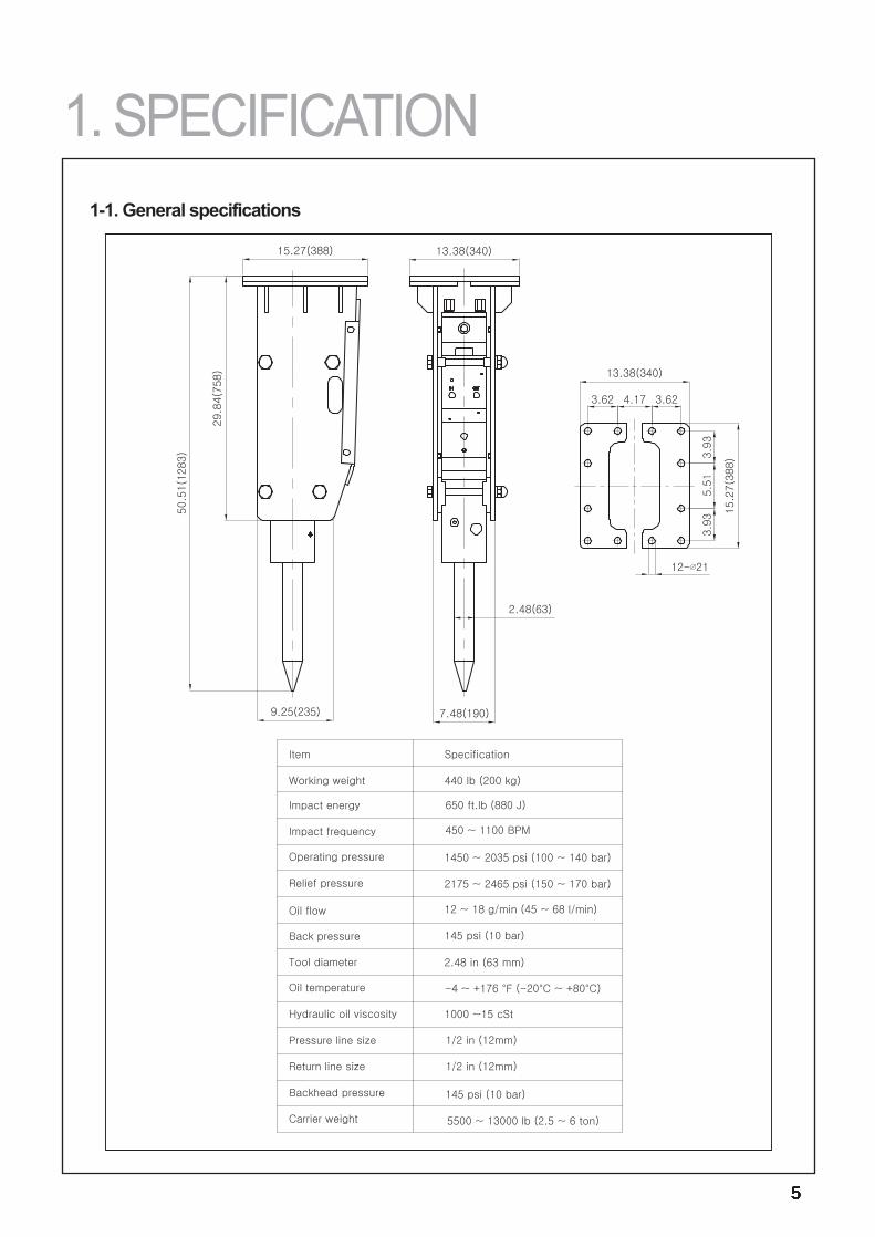
1. SPECIFICATION1-1. General specifications
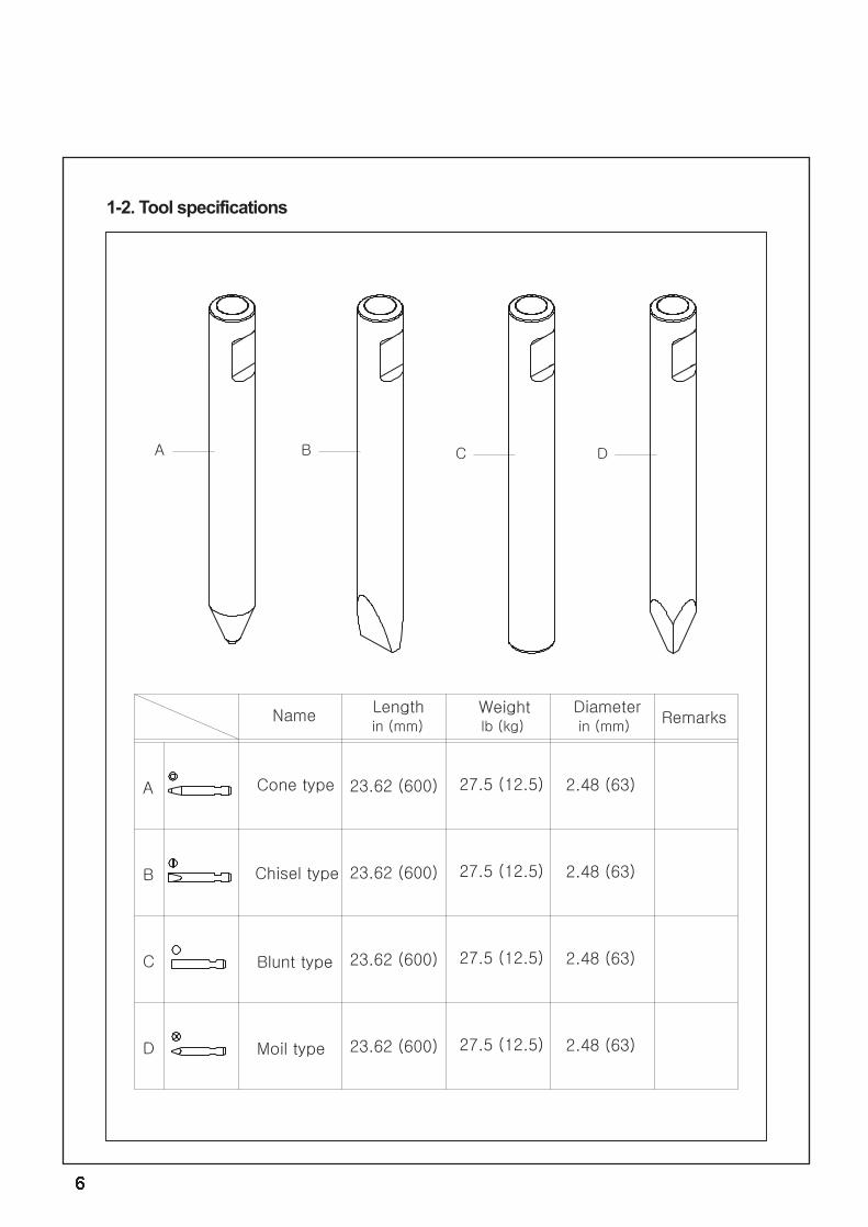
1-2. Tool specifications
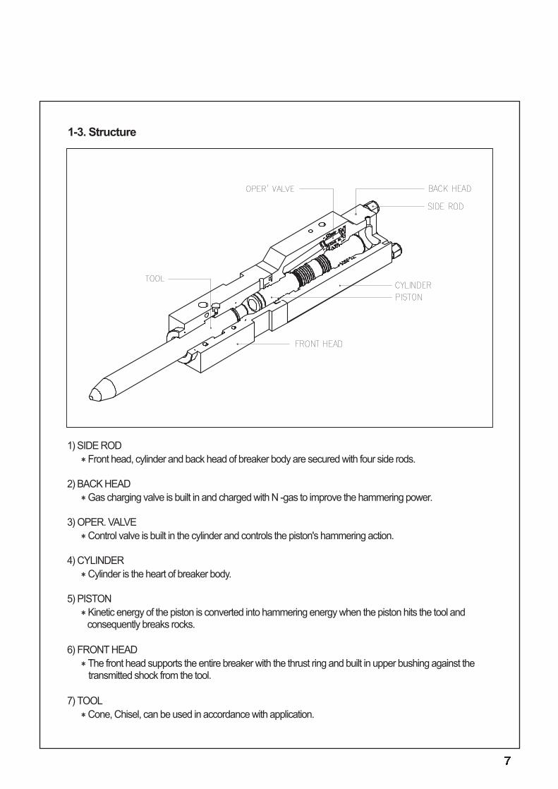
1) SIDE RODFront head, cylinder and back head of breaker body are secured with four side rods.
2) BACK HEADGas charging valve is built in and charged with N -gas to improve the hammering power.
3) OPER. VALVEControl valve is built in the cylinder and controls the piston's hammering action.
4) CYLINDERCylinder is the heart of breaker body.
5) PISTONKinetic energy of the piston is converted into hammering energy when the piston hits the tool and consequently breaks rocks.
6) FRONT HEADThe front head supports the entire breaker with the thrust ring and built in upper bushing against the transmitted shock from the tool.
7) TOOLCone, Chisel, can be used in accordance with application.
1-3. Structure
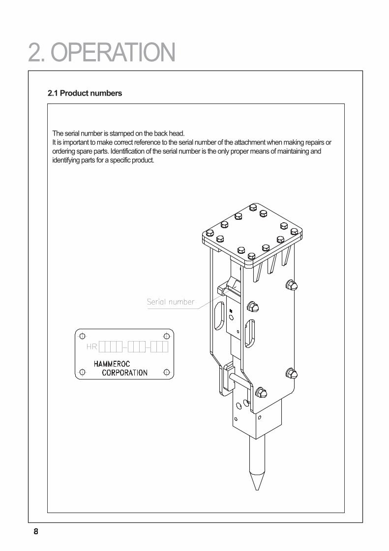
The serial number is stamped on the back head.It is important to make correct reference to the serial number of the attachment when making repairs orordering spare parts. Identification of the serial number is the only proper means of maintaining andidentifying parts for a specific product.
2.1 Product numbers
2. OPERATION
HAMMEROC can offer the selection of standardand special tools to suit each application.The correct type of the tool must be selected to getthe best possible working result and the longest lifetime for tool.
1)BluntFor igneous(e.g. granite) and tough metamorphicrock(e.g.gneiss)into which the tool doesn'tpenetrate.ConcreteBreaking boulders.
2)Chisel and coneFor sedimentary(e.g.sandstone) and weakmetamorphic rock into which the tool penetrates.ConcreteTrenching and benching.
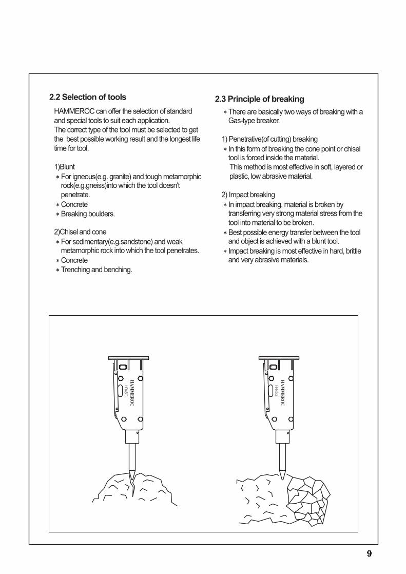
There are basically two ways of breaking with aGas-type breaker.
1) Penetrative(of cutting) breakingIn this form of breaking the cone point or chiseltool is forced inside the material. This method is most effective in soft, layered orplastic, low abrasive material.
2) Impact breakingIn impact breaking, material is broken bytransferring very strong material stress from thetool into material to be broken.Best possible energy transfer between the tooland object is achieved with a blunt tool.Impact breaking is most effective in hard, brittleand very abrasive materials.
2.2 Selection of tools 2.3 Principle of breaking
1) Prepare the carrier as for normal excavationwork.
a. Move the carrier to the required position.b. Engage the parking brake.c. Set the drive to neutral.d. Disengage the boom lock(if fitted)
2) Set the engine speed to the recommendedengine RPM.
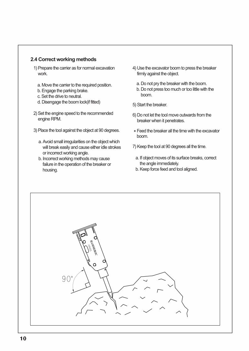
3) Place the tool against the object at 90 degrees.
a. Avoid small irregularities on the object whichwill break easily and cause either idle strokesor incorrect working angle.
b. Incorrect working methods may causefailure in the operation of the breaker orhousing.
4) Use the excavator boom to press the breakerfirmly against the object.
a. Do not pry the breaker with the boom.b. Do not press too much or too little with the
boom.
5) Start the breaker.
6) Do not let the tool move outwards from thebreaker when it penetrates.
Feed the breaker all the time with the excavatorboom.
7) Keep the tool at 90 degrees all the time.
a. If object moves of its surface breaks, correctthe angle immediately.
b. Keep force feed and tool aligned.
2.4 Correct working methods
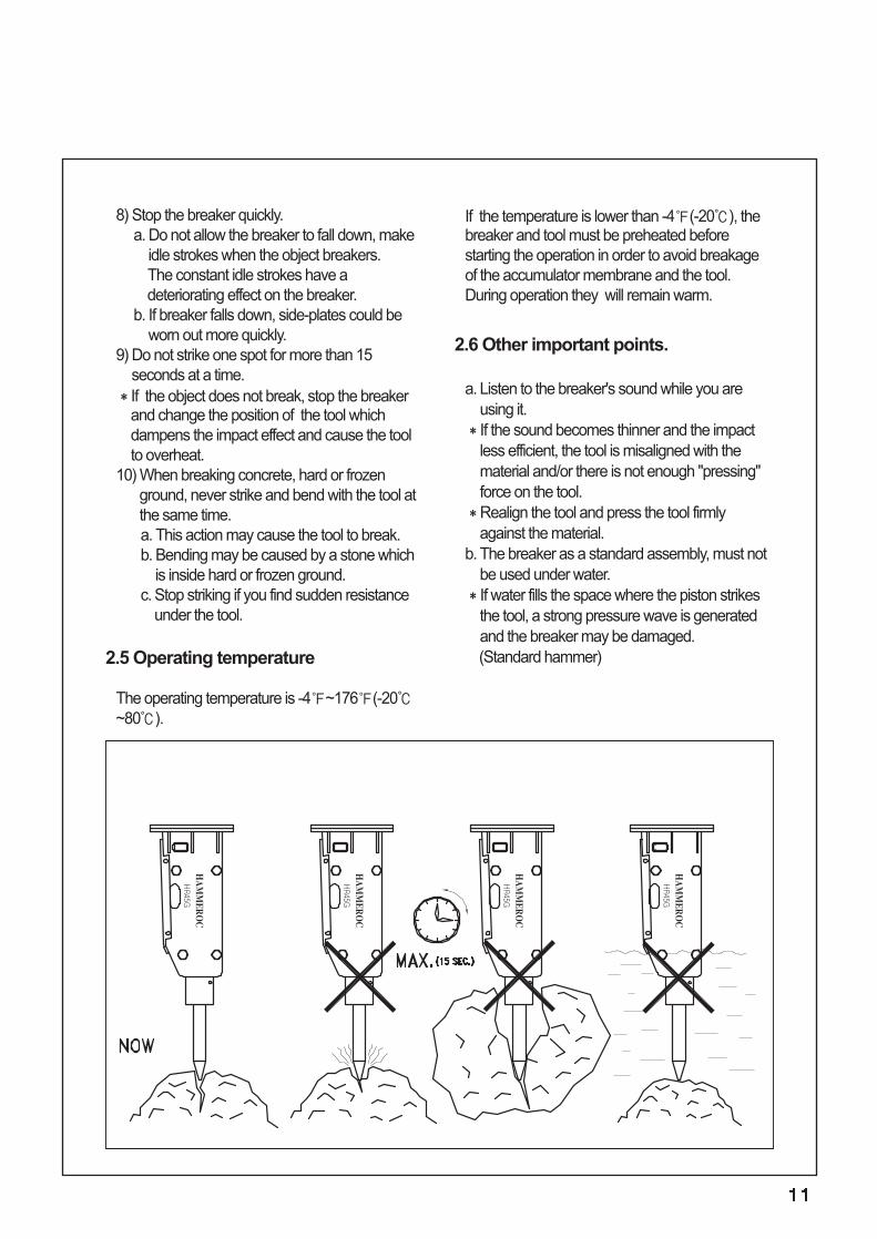
8) Stop the breaker quickly.a. Do not allow the breaker to fall down, make
idle strokes when the object breakers. The constant idle strokes have adeteriorating effect on the breaker.
b. If breaker falls down, side-plates could beworn out more quickly.
9) Do not strike one spot for more than 15seconds at a time.If the object does not break, stop the breakerand change the position of the tool whichdampens the impact effect and cause the toolto overheat.
10) When breaking concrete, hard or frozenground, never strike and bend with the tool atthe same time. a. This action may cause the tool to break.b. Bending may be caused by a stone which
is inside hard or frozen ground.c. Stop striking if you find sudden resistance
under the tool.
2.5 Operating temperature
The operating temperature is -4℉~176℉(-20℃~80℃).
If the temperature is lower than -4℉(-20℃), thebreaker and tool must be preheated beforestarting the operation in order to avoid breakageof the accumulator membrane and the tool.During operation they will remain warm.
2.6 Other important points.
a. Listen to the breaker's sound while you areusing it.If the sound becomes thinner and the impactless efficient, the tool is misaligned with thematerial and/or there is not enough "pressing"force on the tool.Realign the tool and press the tool firmlyagainst the material.
b. The breaker as a standard assembly, must notbe used under water.If water fills the space where the piston strikesthe tool, a strong pressure wave is generatedand the breaker may be damaged. (Standard hammer)
LONG TERM STORAGEObserve the following points when the hammer in stored in the way the vital parts of the attachment areprotected from rust and the machine is ready to be used whenever necessary.
1. The storage area must be dry.2. The tool must be removed from the hammer.3. The lower end of the piston, tool and tool bushing must be well protected with grease in all hydraulic
hammers.4. Connections must be sealed with clean plugs to prevent oil leakage and dirt from getting into couplings.5. The product must be stored in the vertical position.6. Make sure the product can not fall.
2.7 Storage
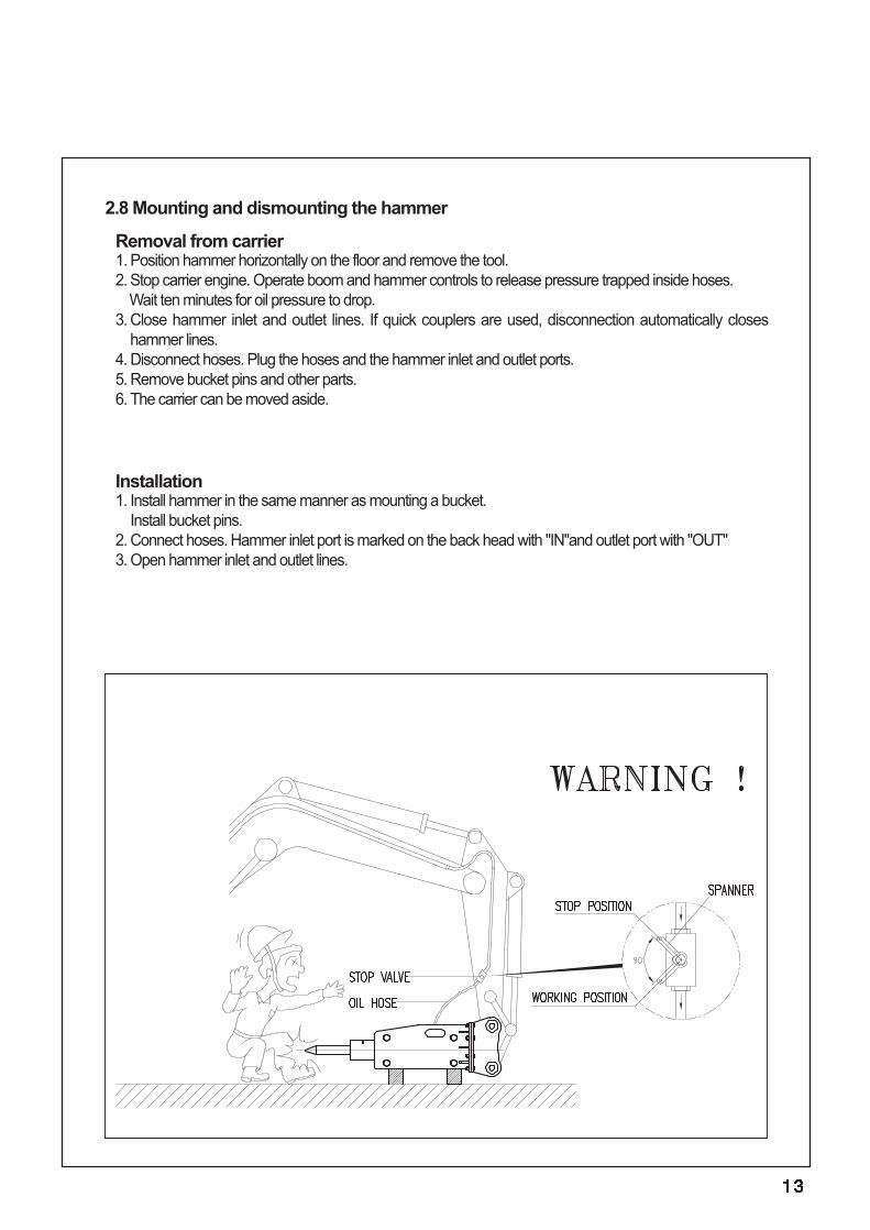
Removal from carrier1. Position hammer horizontally on the floor and remove the tool.2. Stop carrier engine. Operate boom and hammer controls to release pressure trapped inside hoses.
Wait ten minutes for oil pressure to drop.3. Close hammer inlet and outlet lines. If quick couplers are used, disconnection automatically closes
hammer lines.4. Disconnect hoses. Plug the hoses and the hammer inlet and outlet ports.5. Remove bucket pins and other parts.6. The carrier can be moved aside.
Installation1. Install hammer in the same manner as mounting a bucket.
Install bucket pins.2. Connect hoses. Hammer inlet port is marked on the back head with "IN"and outlet port with "OUT"3. Open hammer inlet and outlet lines.
2.8 Mounting and dismounting the hammer
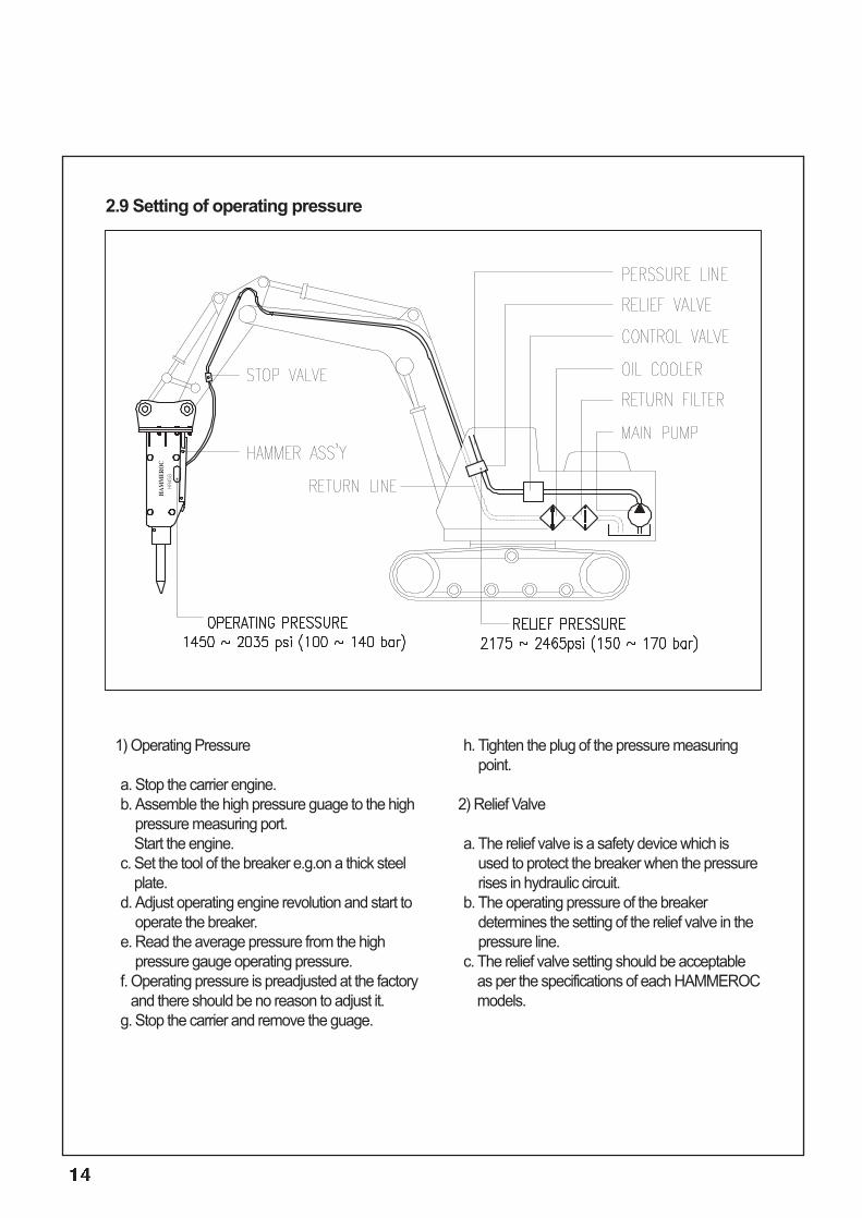
1) Operating Pressure
a. Stop the carrier engine.b. Assemble the high pressure guage to the high
pressure measuring port.Start the engine.
c. Set the tool of the breaker e.g.on a thick steelplate.
d. Adjust operating engine revolution and start tooperate the breaker.
e. Read the average pressure from the highpressure gauge operating pressure.
f. Operating pressure is preadjusted at the factoryand there should be no reason to adjust it.
g. Stop the carrier and remove the guage.
h. Tighten the plug of the pressure measuringpoint.
2) Relief Valve
a. The relief valve is a safety device which isused to protect the breaker when the pressurerises in hydraulic circuit.
b. The operating pressure of the breakerdetermines the setting of the relief valve in thepressure line.
c. The relief valve setting should be acceptableas per the specifications of each HAMMEROCmodels.
2.9 Setting of operating pressure
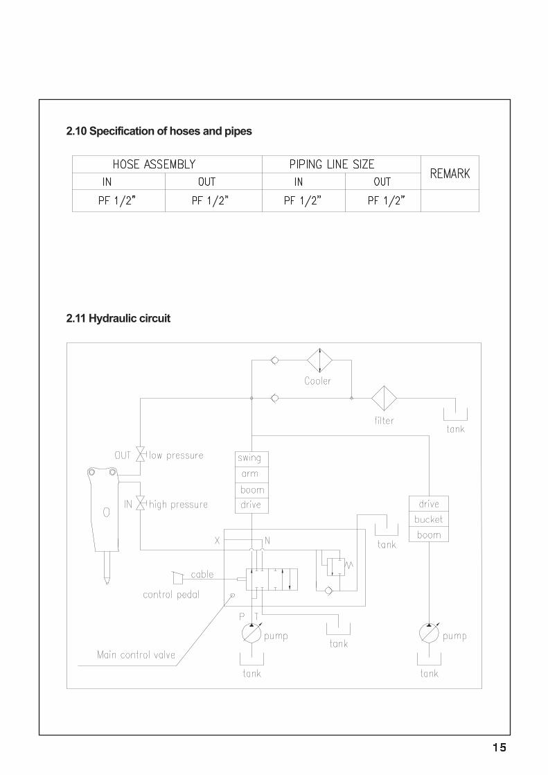
2.10 Specification of hoses and pipes
2.11 Hydraulic circuit
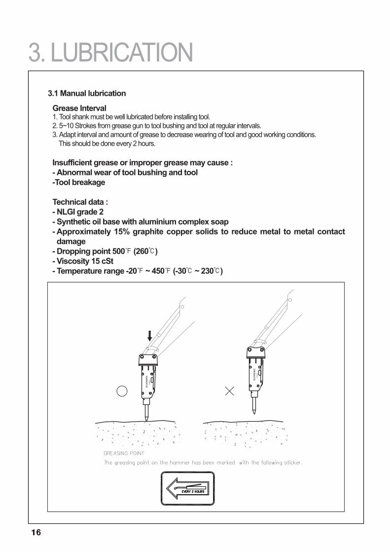
Grease Interval1. Tool shank must be well lubricated before installing tool.2. 5~10 Strokes from grease gun to tool bushing and tool at regular intervals.3. Adapt interval and amount of grease to decrease wearing of tool and good working conditions.
This should be done every 2 hours.
Insufficient grease or improper grease may cause : - Abnormal wear of tool bushing and tool-Tool breakage
Technical data : - NLGI grade 2- Synthetic oil base with aluminium complex soap- Approximately 15% graphite copper solids to reduce metal to metal contactdamage
- Dropping point 500℉ (260℃)- Viscosity 15 cSt- Temperature range -20℉ ~ 450℉ (-30℃ ~ 230℃)
3.1 Manual lubrication
3. LUBRICATION
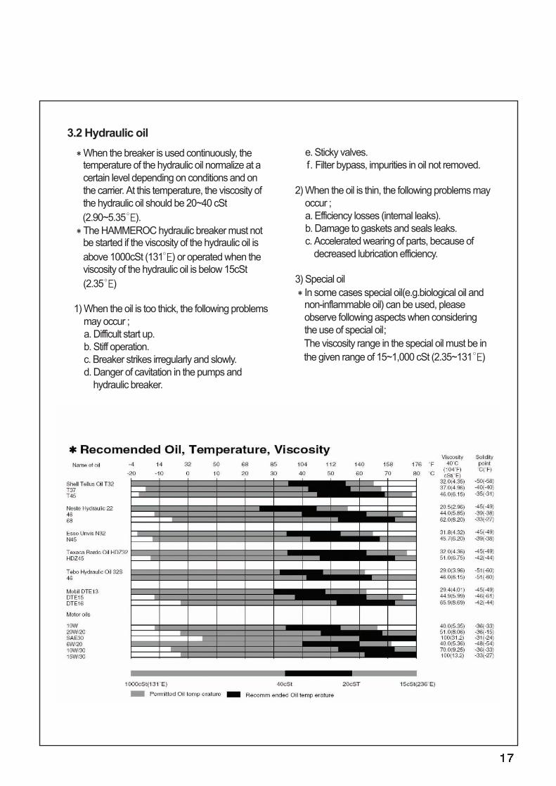
When the breaker is used continuously, thetemperature of the hydraulic oil normalize at acertain level depending on conditions and onthe carrier. At this temperature, the viscosity ofthe hydraulic oil should be 20~40 cSt(2.90~5.35°E).The HAMMEROC hydraulic breaker must notbe started if the viscosity of the hydraulic oil isabove 1000cSt (131°E) or operated when theviscosity of the hydraulic oil is below 15cSt(2.35°E)
1) When the oil is too thick, the following problemsmay occur ;a. Difficult start up.b. Stiff operation.c. Breaker strikes irregularly and slowly.d. Danger of cavitation in the pumps and
hydraulic breaker.
e. Sticky valves.f. Filter bypass, impurities in oil not removed.
2) When the oil is thin, the following problems mayoccur ;a. Efficiency losses (internal leaks).b. Damage to gaskets and seals leaks. c. Accelerated wearing of parts, because of
decreased lubrication efficiency.
3) Special oilIn some cases special oil(e.g.biological oil andnon-inflammable oil) can be used, pleaseobserve following aspects when consideringthe use of special oil;The viscosity range in the special oil must be inthe given range of 15~1,000 cSt (2.35~131°E)
3.2 Hydraulic oil
4) Cleanness of hydraulic oilThe hydraulic oil filter of the carrier will clean theoil flowing through the breaker.The purpose of the oil filter is to remove impuritiesfrom the hydraulic oil since they causeaccelerated component wear, blockages andeven seizure.Impurities also cause the oil to overheat and deteriorate.Air and water are also impurities in oil.
5) Oil filterWhen working with hydraulic breaker, the carrieroil filter must fulfil the following specifications;
a. The oil filter must be rated at 25 micronsmaximum.
b. The oil filter must be a standard return line filterrated to maximum working pressure.
c. The oil filter must have a volume flow capacity ofat least twice the breaker's maximum flow.
d. The cooler must withstand a dynamic pressureof 290 psi(20bar).
e. If the carrier's oil cooler is too small either theoriginal cooler must be replaced with a largerone or an auxiliary cooler must be installed.
6) The auxiliary hydraulic cooler can be installed;a. In front of the radiator, in which case an
additional fan is not required, i.e. maximum riseof the cooling air is 40℉ (5℃).
b. Any other suitable place, using a fan eitherhydraulically or electrically driven.
7) Damage caused by hydraulic oil contamination inthe carrier and breaker circuits;
a. The working life of the pumps is significantlyshortened.-Premature wear of parts-Cavitation
b. Valves do not function properly. -Spools bind-Premature wear of parts-Blocking of small holes
c. Wear of cylinders and gaskets.d. Reduced breaker efficiency.
-Premature wear of moving parts and seals(Danger of piston seizing up Oil overheats)
e. Shorten working life and reduced efficiency ofhydraulic oil.-Oil overheats-Oil quality deterioration-Electrochemical changes in hydraulic oil
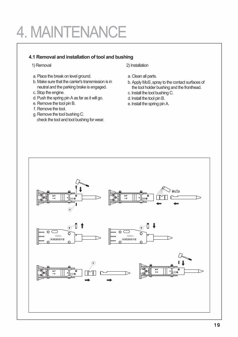
1) Removal
a. Place the break on level ground. b. Make sure that the carrier's transmission is in
neutral and the parking brake is engaged.c. Stop the engine.d. Push the spring pin A as far as it will go.e. Remove the tool pin B.f. Remove the tool.g. Remove the tool bushing C.
check the tool and tool bushing for wear.
2) Installation
a. Clean all parts.b. Apply MoS₂spray to the contact surfaces of
the tool holder bushing and the fronthead.c. Install the tool bushing C.d. Install the tool pin B.e. Install the spring pin A.
4.1 Removal and installation of tool and bushing
4. MAINTENANCE
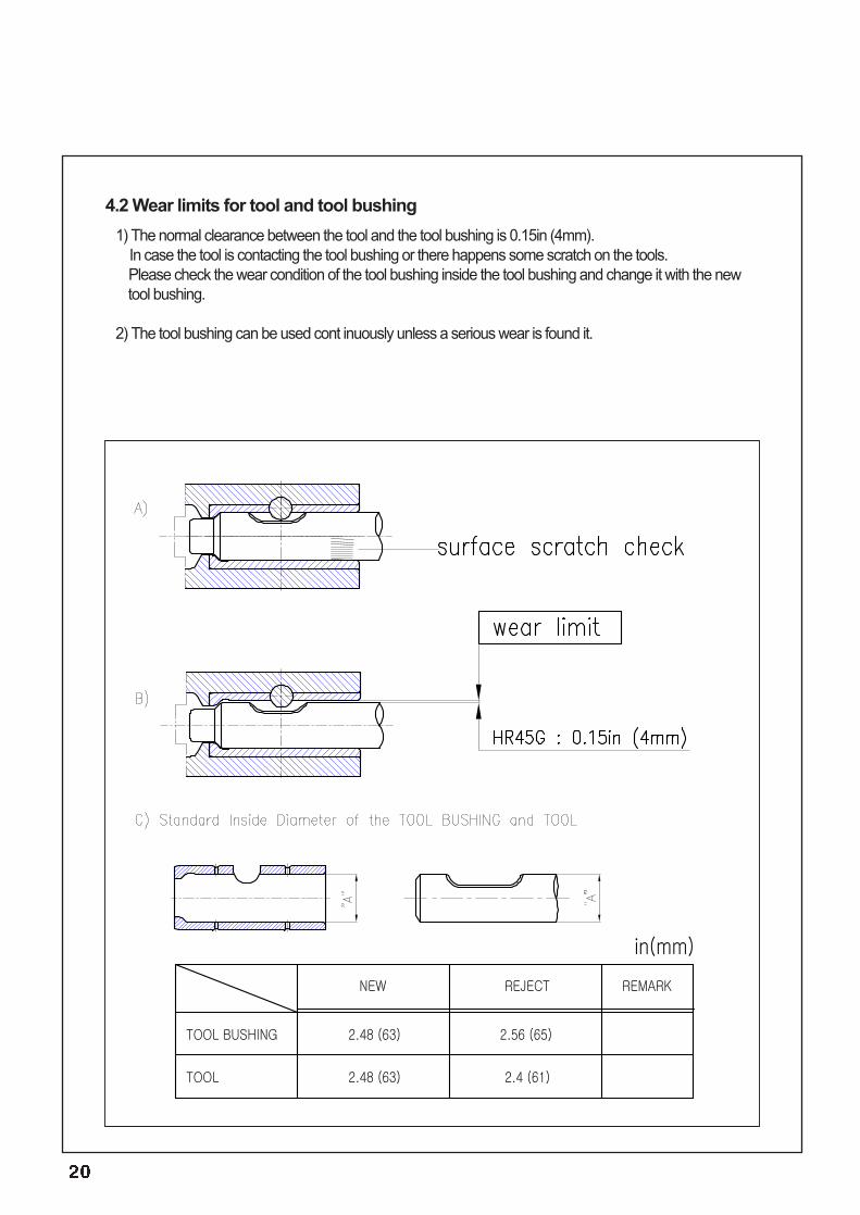
1) The normal clearance between the tool and the tool bushing is 0.15in (4mm).In case the tool is contacting the tool bushing or there happens some scratch on the tools.Please check the wear condition of the tool bushing inside the tool bushing and change it with the newtool bushing.
2) The tool bushing can be used cont inuously unless a serious wear is found it.
4.2 Wear limits for tool and tool bushing
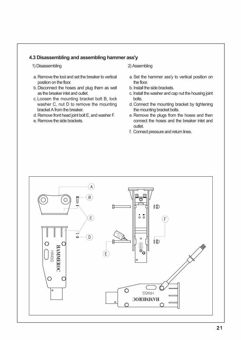
1) Disassembling
a. Remove the tool and set the breaker to verticalposition on the floor.
b. Disconnect the hoses and plug them as wellas the breaker inlet and outlet.
c. Loosen the mounting bracket bolt B, lockwasher C, nut D to remove the mountingbracket A from the breaker.
d. Remove front head joint bolt E, and washer F.e. Remove the side brackets.
2) Assembling
a. Set the hammer ass'y to vertical position onthe floor.
b. Install the side brackets.c. Install the washer and cap nut the housing joint
bolts.d. Connect the mounting bracket by tightening
the mounting bracket bolts.e. Remove the plugs from the hoses and then
connect the hoses and the breaker inlet andoutlet.
f. Connect pressure and return lines.
4.3 Disassembling and assembling hammer ass'y
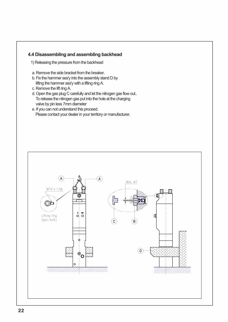
1) Releasing the pressure from the backhead
a. Remove the side bracket from the breaker.b. Fix the hammer ass'y into the assembly stand D by
lifting the hammer ass'y with a lifting ring A.c. Remove the lift ring A.d. Open the gas plug C carefully and let the nitrogen gas flow out..
To release the nitrogen gas put into the hole at the charging valve by pin less 7mm diameter
e. If you can not understand this proceed.Please contact your dealer in your territory or manufacturer.
4.4 Disassembling and assembling backhead
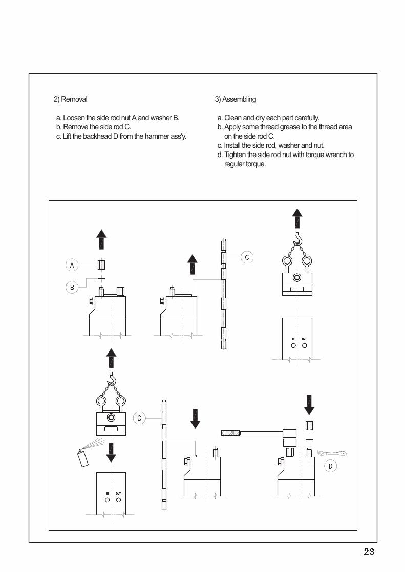
2) Removal
a. Loosen the side rod nut A and washer B.b. Remove the side rod C.c. Lift the backhead D from the hammer ass'y.
3) Assembling
a. Clean and dry each part carefully.b. Apply some thread grease to the thread area
on the side rod C.c. Install the side rod, washer and nut.d. Tighten the side rod nut with torque wrench to
regular torque.
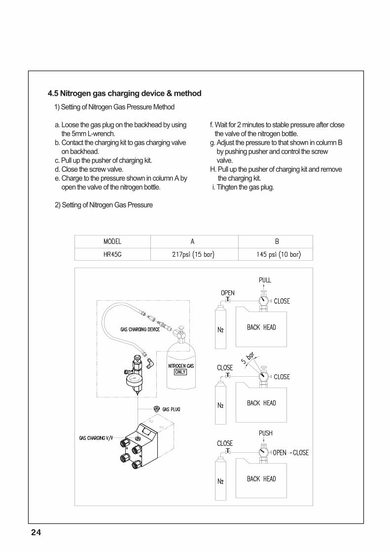
1) Setting of Nitrogen Gas Pressure Method
a. Loose the gas plug on the backhead by usingthe 5mm L-wrench.
b. Contact the charging kit to gas charging valveon backhead.
c. Pull up the pusher of charging kit.d. Close the screw valve.e. Charge to the pressure shown in column A by
open the valve of the nitrogen bottle.
2) Setting of Nitrogen Gas Pressure
f. Wait for 2 minutes to stable pressure after closethe valve of the nitrogen bottle.
g. Adjust the pressure to that shown in column Bby pushing pusher and control the screwvalve.
H. Pull up the pusher of charging kit and removethe charging kit.
i. Tihgten the gas plug.
4.5 Nitrogen gas charging device & method
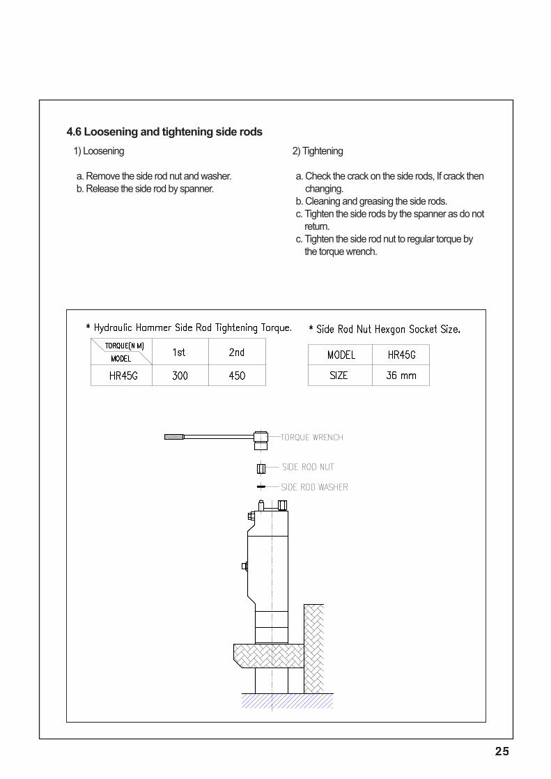
1) Loosening
a. Remove the side rod nut and washer.b. Release the side rod by spanner.
2) Tightening
a. Check the crack on the side rods, If crack thenchanging.
b. Cleaning and greasing the side rods.c. Tighten the side rods by the spanner as do not
return.c. Tighten the side rod nut to regular torque by
the torque wrench.
4.6 Loosening and tightening side rods
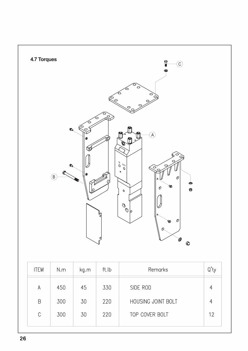
4.7 Torques
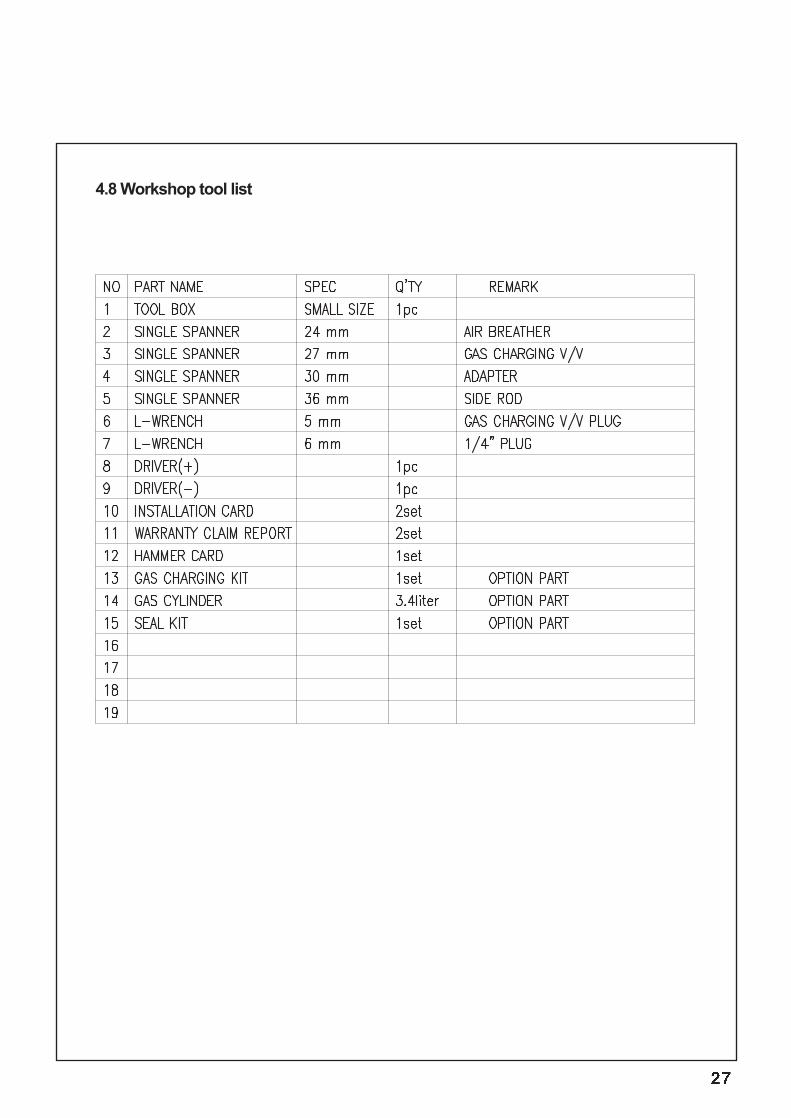
4.8 Workshop tool list
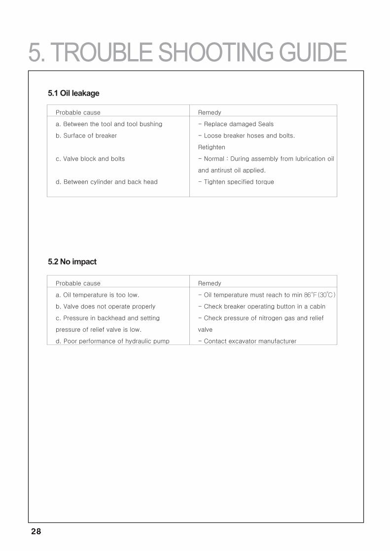
86℉(30℃)
5.1 Oil leakage
5.2 No impact
5. TROUBLE SHOOTING GUIDE
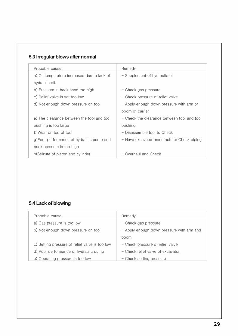
5.3 Irregular blows after normal
5.4 Lack of blowing
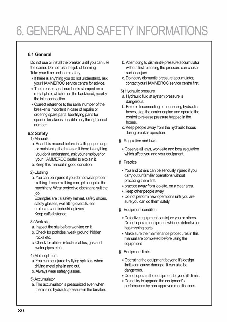
Do not use or install the breaker untill you can usethe carrier. Do not rush the job of learning. Take your time and learn safety.
If there is anything you do not understand, askyour HAMMEROC service centre for advice.The breaker serial number is stamped on ametal plate, which is on the backhead, nearbythe inlet connectionCorrect reference to the serial number of thebreaker is important in case of repairs orordering spare parts. Identifying parts forspecific breaker is possible only through serialnumber.
6.2 Safety1) Manualsa. Read this maunal before installing, operating
or maintaning the breaker. If there is anythingyou don't understand, ask your employer oryour HAMMEROC dealer to explain it.
b. Keep this manual in good condition.
2) Clothinga. You can be injured if you do not wear proper
clothing. Loose clothing can get caught in themachinery. Wear protective clothing to suit thejob.Examples are : a safety helmet, safety shoes,safety glasses, well-fitting overalls, ear-protectors and industrial gloves.Keep cuffs fastened.
3) Work sitea. Inspect the site before working on it.b. Check for potholes, weak ground, hidden
rocks etc.c. Check for utilities (electric cables, gas and
water pipes etc.).
4) Metal splintersa. You can be injured by flying splinters when
driving metal pins in and out.b. Always wear safety glasses.
5) Accumulatora. The accumulator is pressurized even when
there is no hydraulic pressure in the breaker.
b. Attempting to dismantle pressure accumulatorwithout first releasing the pressure can causesurious injury.
c. Do not try dismantle pressure accumulator,contact your HAMMEROC service centre first.
6) Hydraulic pressurea. Hydraulic fluid at system pressure is
dangerous.b. Before disconnecting or connecting hydraulic
hoses, stop the carrier engine and operate thecontrol to release pressure trapped in thehoses.
c. Keep people away from the hydraulic hosesduring breaker operation.
Regulation and laws
Observe all laws, work-site and local regulationwhich affect you and your equipment.
Practice
You and others can be seriously injured if youcarry out unfamiliar operations withoutpracticing them first.practice away from job-site, on a clear area.Keep other people away.Do not perform new operations until you aresure you can do them safely.
Equipment condition
Defective equipment can injure you or others.Do not operate equipment which is detective orhas missing parts.Make sure the maintenance procedures in thismanual are completed before using theequipment.
Equipment limits
Operating the equipment beyond it’s designlimits can cause damage. It can also bedangerous.Do not operate the equipment beyond it’s limits.Do not try to upgrade the equipment'sperformance by non-approved modifications.
6.1 General
6. GENERAL AND SAFETY INFORMATIONS

Excellent MachineMechanism, MaterialISO 9001
CONTENTS
33
35
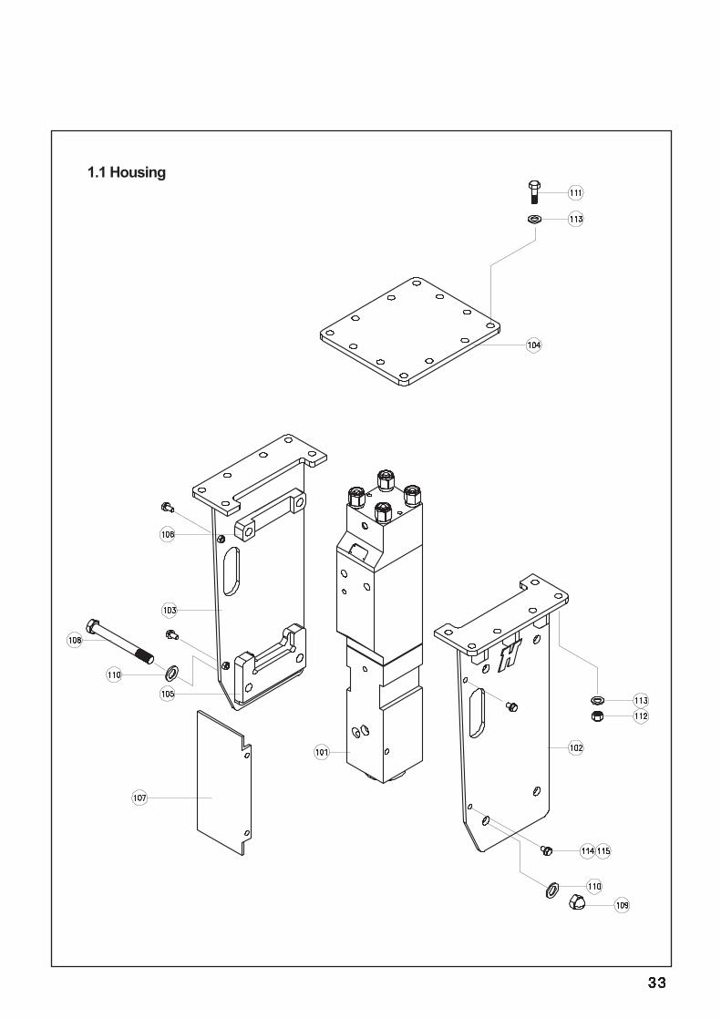
1.1 Housing

101 A0506000 HAMMER ASSEMBLY 1102 A050A500 HOUSING ASSEMBLY (RIGHT) 1103 A050A510 HOUSING ASSEMBLY (LEFT) 1104 A060A030 TOP PLATE 1105 A0501040 PLATE 2106 A0501050 PLATE 2107 A0501150 PLATE 1108 HB1820210 BOLT 4109 CN182000 CAP NUT 4110 SW180000 WASHER 8111 HB1820060 BOLT (TOP) 12112 NN182000 NUT (TOP) 12113 CW180000 WASHER (TOP) 24114 HB1212525 BOLT 4115 SW120000 WASHER 4
NO PART NO. PART NAME Q’TY REMARK
MODEL HR 45G
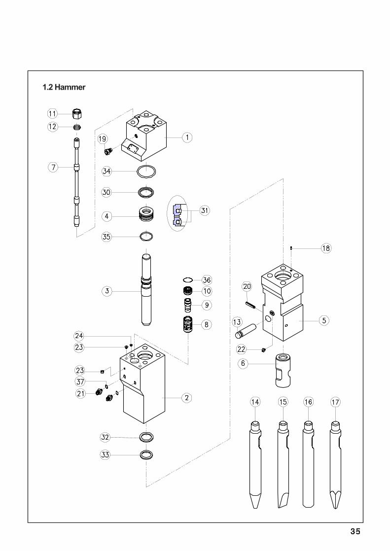
1.2 Hammer

1 A0506010 BACK HEAD 12 A0506020 CYLINDER 13 A0506030 PISTON 14 A0506040 SEAL HOUSING 15 A0506050 FRONT HEAD 167
A0506060A0506070
TOOL BUSHINGSIDE ROD
14
8 A0506080 OPER VALVE SPOOL GUIDE1. 19 A0506090 OPER VALVE SPOOL GUIDE2. 110 A0506100 OPER VALVE SPOOL 111 HN243000 SIDE ROD NUT 412 A0506110 SIDE ROD WASHER 413 A0506120 TOOL PIN 114 B0406220 TOOL - CONE 115 B0406230 TOOL - CHISEL 116 B0406240 TOOL - BLUNT 117 A0406500 TOOL - MOIL 118 B4006370 GUIDE PIN 119 A3006370 GAS CHARGING VALVE 12021
SP100000A0206180
SPRING PIN 12
22 B4006560 GREASE NIPPLEADAPTER (IN,OUT)
123 B4006450 HEX.SOCKET PLUG 324 A0506130 HEX.SOCKET PLUG 1
31 A0507020 STEP SEAL 232 A0507030 SEAL 133 A0507040 WIPER 134 B1507120 O-RING 135 A2007120 O-RING 136 A0507050 O-RING 137 A0207070 O-RING 2
1SET
NO PART NO. PART NAME Q’TY REMARK
MODEL HR 45G
30 A0507010 GAS SEAL 1
A0507000 SEAL SET


14749 Carmenita Road Norwalk, CA 90650 U.S.A TEL : 562-926-2014 FAX : 562-926-9614
E-mail : [email protected] Web Site : www.hammeroc.com