iso cylinder series c85 - smc pneumatics · iso cylinder series c85 ø8, ø10, ø12, ø16, ø20,...
TRANSCRIPT
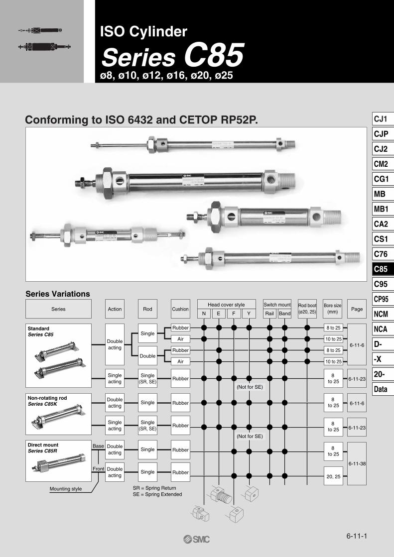
ISO Cylinder
Series C85ø8, ø10, ø12, ø16, ø20, ø25
Conforming to ISO 6432 and CETOP RP52P.
Series Variations
Series RodRod boot(ø20, 25) Page
SingleRubber 8 to 25
10 to 25
8 to 25
10 to 25
Air
Rubber
Air
Rubber
Double
Single(SR, SE)
Action Cushion
Doubleacting
Singleacting
RubberSingleDoubleacting
RubberSingle
(SR, SE)Singleacting
StandardSeries C85
Non-rotating rodSeries C85K
RubberSingle
RubberSingle
SR = Spring ReturnSE = Spring Extended
Mounting style
Front
BaseDirect mountSeries C85R
Head cover style
N E F Y
Bore size(mm)
6-11-23
6-11-6
6-11-23
6-11-38
8 to 25
6-11-6
Switch mount
Rail Band
Doubleacting
Doubleacting
8 to 25
8 to 25
8 to 25
20, 25
(Not for SE)
(Not for SE)
6-11-1
CJ1
CJP
CJ2
CM2
CG1
MB
MB1
CA2
CS1
C76
C85
C95
CP95
NCM
NCA
D-
-X
20-
Data
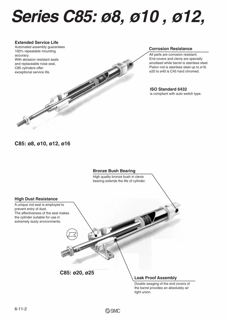
Series C85: ø8, ø10 , ø12,
ISO Standard 6432is compliant with auto switch type.
Extended Service Life Automated assembly guarantees 100% repeatable mounting accuracy.With abrasion resistant seals and replaceable nose seal, C85 cylinders offerexceptional service life.
C85: ø8, ø10, ø12, ø16
C85: ø20, ø25
High quality bronze bush in clevis bearing extends the life of cylinder.
Bronze Bush Bearing
A unique rod seal is employed to prevent entry of dust.The effectiveness of the seal makes the cylinder suitable for use inextremely dusty environments.
High Dust Resistance
Double swaging of the end covers of the barrel provides an absolutely air tight union.
Leak Proof Assembly
All parts are corrosion resistant.End covers and clevis are specially anodised while barrel is stainless steel.Piston rod is stainless steel up to ø16.ø20 to ø40 is C45 hard chromed.
Corrosion Resistance
6-11-2
Bandmounting
Railmounting
Rod boot(Only ø20, ø25)
VariationsSeries Action
Rubbercushion
Singleacting,Springreturn
Singleacting,Spring
extended
Doubleacting,
Single rod
Doubleacting,
Double rod
C85
8 10 12 16 20 25
Bore size (mm)
Basic integrated clevis (N)
Double end (E)
Front nose in line port (Y)
Auto switchFront nose-XB6Hightemp.
-XB7Low
temp.
-XB9Low
speed
-XC4Heavyduty
scraper R R2
Only bores ø20, ø25 mm Bore ø8 to ø16 and all non-rotating piston rod are
already Stainless steel
Aircushion
Nonrotating
Rubbercushion
Aircushion
Rubbercushion
Nonrotating
Rubbercushion
Nonrotating
Stainless steel piston rod,
rod end nut and mounting nut
Stainless steel piston rod and
rod end nut
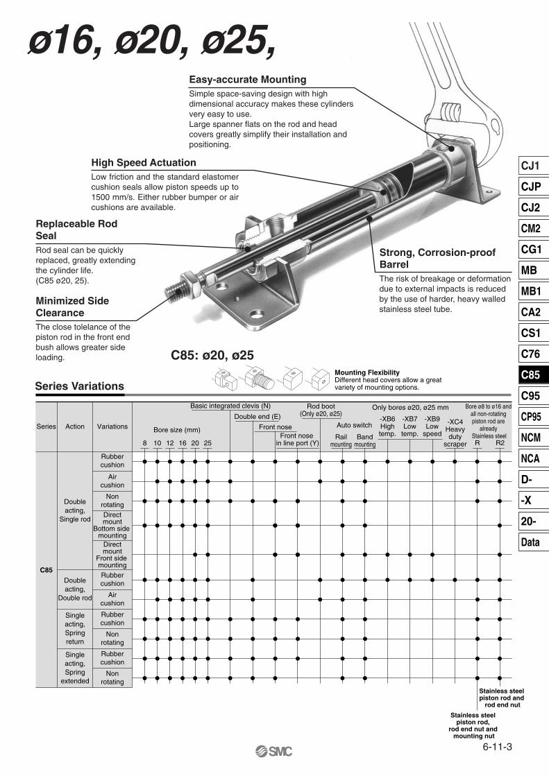
Mounting FlexibilityDifferent head covers allow a greatvariety of mounting options.Series Variations
Directmount
Bottom side mounting
Directmount
Front side mounting
ø16, ø20, ø25,Simple space-saving design with high dimensional accuracy makes these cylinders very easy to use.Large spanner flats on the rod and head covers greatly simplify their installation and positioning.
Low friction and the standard elastomer cushion seals allow piston speeds up to 1500 mm/s. Either rubber bumper or air cushions are available.
Rod seal can be quickly replaced, greatly extending the cylinder life.(C85 ø20, 25).
The close tolelance of the piston rod in the front end bush allows greater side loading. C85: ø20, ø25
The risk of breakage or deformation due to external impacts is reduced by the use of harder, heavy walled stainless steel tube.
Easy-accurate Mounting
High Speed Actuation
Replaceable Rod Seal
Minimized SideClearance
Strong, Corrosion-proofBarrel
6-11-3
CJ1
CJP
CJ2
CM2
CG1
MB
MB1
CA2
CS1
C76
C85
C95
CP95
NCM
NCA
D-
-X
20-
Data
6-11-5
CJ1
CJP
CJ2
CM2
CG1
MB
MB1
CA2
CS1
C76
C85
C95
CP95
NCM
NCA
D-
-X
20-
Data
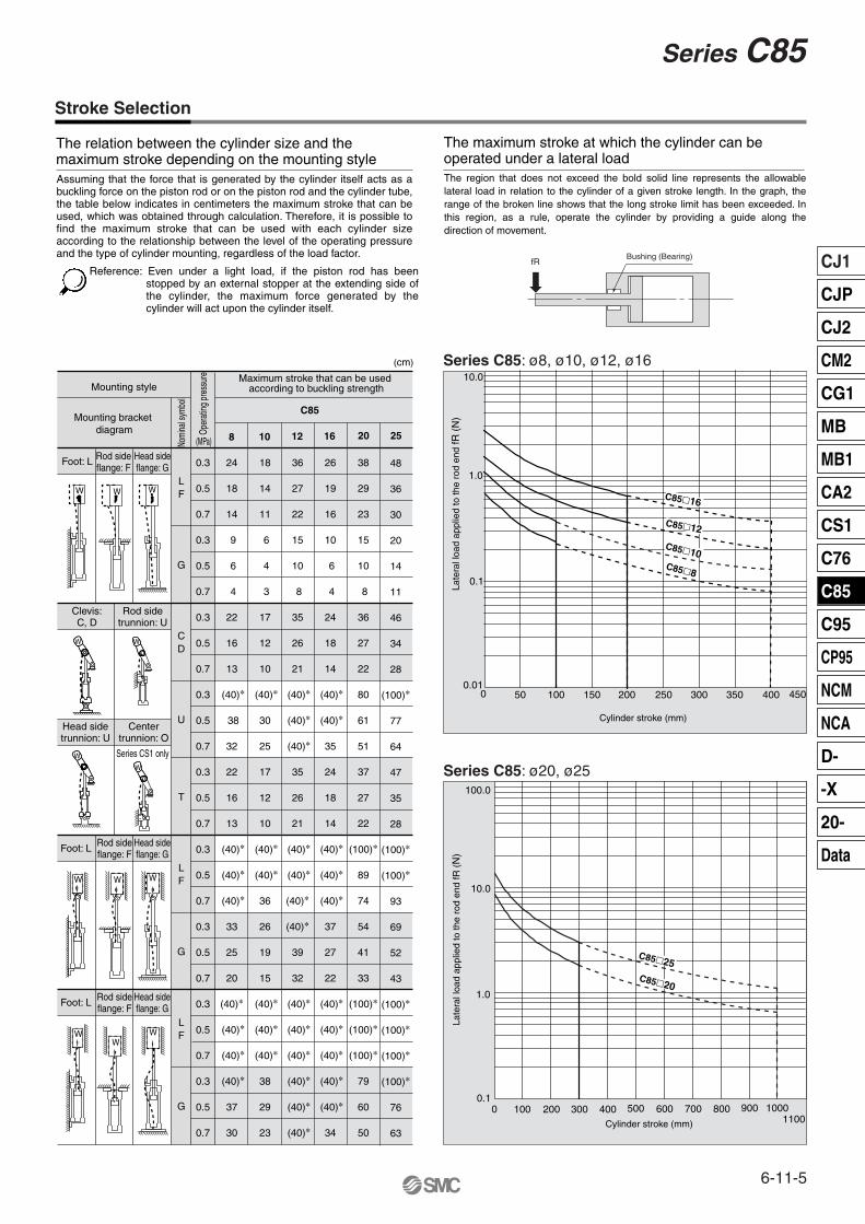
Series C85
Stroke Selection
The relation between the cylinder size and the maximum stroke depending on the mounting style
The maximum stroke at which the cylinder can be operated under a lateral load
0.3
0.5
0.7
0.3
0.5
0.7
0.3
0.5
0.7
0.3
0.5
0.7
0.3
0.5
0.7
0.3
0.5
0.7
0.3
0.5
0.7
0.3
0.5
0.7
0.3
0.5
0.7
24
18
14
9
6
4
22
16
13
(40)∗
38
32
22
16
13
(40)∗
(40)∗
(40)∗
33
25
20
(40)∗
(40)∗
(40)∗
(40)∗
37
30
18
14
11
6
4
3
17
12
10
(40)∗
30
25
17
12
10
(40)∗
(40)∗
36
26
19
15
(40)∗
(40)∗
(40)∗
38
29
23
36
27
22
15
10
8
35
26
21
(40)∗
(40)∗
(40)∗
35
26
21
(40)∗
(40)∗
(40)∗
(40)∗
39
32
(40)∗
(40)∗
(40)∗
(40)∗
(40)∗
(40)∗
26
19
16
10
6
4
24
18
14
(40)∗
(40)∗
35
24
18
14
(40)∗
(40)∗
(40)∗
37
27
22
(40)∗
(40)∗
(40)∗
(40)∗
(40)∗
34
38
29
23
15
10
8
36
27
22
80
61
51
37
27
22
(100)∗
89
74
54
41
33
(100)∗
(100)∗
(100)∗
79
60
50
48
36
30
20
14
11
46
34
28
(100)∗
77
64
47
35
28
(100)∗
(100)∗
93
69
52
43
(100)∗
(100)∗
(100)∗
(100)∗
76
63
8 10 12 16 20 25
L
F
G
C
D
U
T
L
F
G
L
F
G
Mounting styleMaximum stroke that can be used
according to buckling strength
C85Mounting bracket
diagram
Nomi
nal s
ymbo
l
Oper
ating
pre
ssur
e
Foot: L Rod sideflange: F
Head sideflange: G
Foot: L Rod sideflange: F
Head sideflange: G
Foot: L Rod sideflange: F
Head sideflange: G
Clevis:C, D
Rod sidetrunnion: U
Centertrunnion: O
Head sidetrunnion: U
Series CS1 only
W W W
WW W
W W
W
W
WW
W
(MPa)
Assuming that the force that is generated by the cylinder itself acts as a buckling force on the piston rod or on the piston rod and the cylinder tube, the table below indicates in centimeters the maximum stroke that can be used, which was obtained through calculation. Therefore, it is possible to find the maximum stroke that can be used with each cylinder size according to the relationship between the level of the operating pressure and the type of cylinder mounting, regardless of the load factor.
Reference: Even under a light load, if the piston rod has been stopped by an external stopper at the extending side of the cylinder, the maximum force generated by the cylinder will act upon the cylinder itself.
Bushing (Bearing)fR
The region that does not exceed the bold solid line represents the allowable lateral load in relation to the cylinder of a given stroke length. In the graph, the range of the broken line shows that the long stroke limit has been exceeded. In this region, as a rule, operate the cylinder by providing a guide along the direction of movement.
Series C85: ø8, ø10, ø12, ø16
Late
ral l
oad
appl
ied
to th
e ro
d en
d fR
(N
)
40035030025020015010050 4500
0.1
10.0
0.01
1.0
Cylinder stroke (mm)
C85�8
C85�16
C85�12
C85�10
Late
ral l
oad
appl
ied
to th
e ro
d en
d fR
(N
)
Cylinder stroke (mm)
Series C85: ø20, ø25
1.0
100.0
0.1
10.0
600500400300 10001100
9008007002001000
C85�25C85�20
(cm)
6-11-6
ISO Cylinder: Standard/Non-rotating TypeDouble Acting, Single/Double Rod
Series C85ø8, ø10, ø12, ø16, ø20, ø25
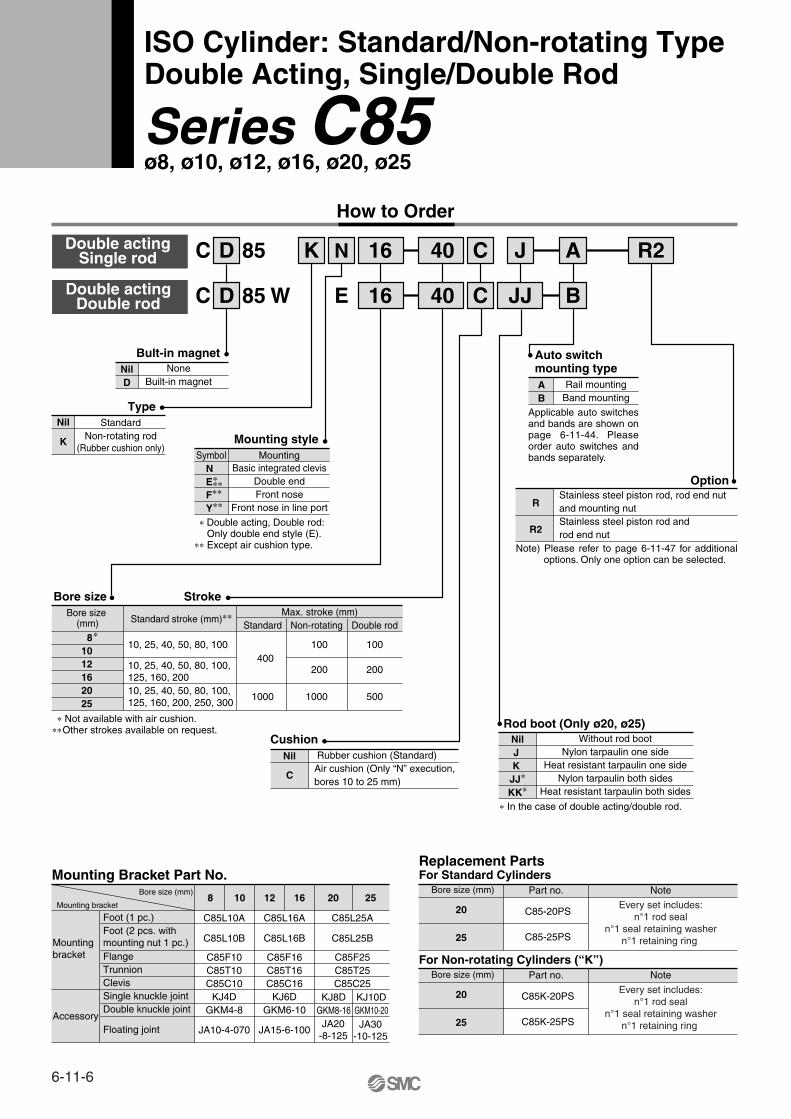
How to Order
Double actingDouble rod
Double actingSingle rod
D 85 WC
D 85C K N 16 C
E 16
40
40
R2
C
A
B
Bult-in magnet
Type
Bore size Stroke
Symbol
Mounting style
Basic integrated clevisDouble endFront nose
Front nose in line port
NilD
NoneBuilt-in magnet
Nil Standard
Nil
Cushion Rubber cushion (Standard)Air cushion (Only “N” execution,bores 10 to 25 mm)
Auto switchmounting typeAB
Rail mountingBand mounting
Rod boot (Only ø20, ø25)
J
JJ
K Non-rotating rod(Rubber cushion only)
NE∗
F∗∗
Y∗∗
∗ Double acting, Double rod:Only double end style (E).
∗∗ Except air cushion type.
C
Mounting bracket
Bore size (mm)
Mounting Bracket Part No.
NilJ K
JJ∗
KK∗
Without rod bootNylon tarpaulin one side
Heat resistant tarpaulin one sideNylon tarpaulin both sides
Heat resistant tarpaulin both sides
∗ In the case of double acting/double rod.
Option
Foot (1 pc.)
Floating joint
Foot (2 pcs. withmounting nut 1 pc.)
Accessory
Mounting bracket Flange
TrunnionClevisSingle knuckle jointDouble knuckle joint
8 10 12 16
C85L10A
C85L10B
JA10-4-070
C85F10C85T10C85C10
KJ4DGKM4-8
C85L16A
C85L16B
JA15-6-100
C85F16C85T16C85C16
KJ6DGKM6-10
20 25
C85L25A
C85L25B
C85F25C85T25C85C25
KJ8DGKM8-16
KJ10DGKM10-20JA30
-10-125JA20
-8-125
Bore size (mm)
Replacement PartsFor Standard Cylinders
20
25
Part no. Note
C85-20PS
C85-25PS
Every set includes:n°1 rod seal
n°1 seal retaining washern°1 retaining ring
Bore size (mm)
For Non-rotating Cylinders (“K”)
20
25
Part no. Note
C85K-20PS
C85K-25PS
Every set includes:n°1 rod seal
n°1 seal retaining washern°1 retaining ring
Mounting
R
R2
Stainless steel piston rod, rod end nut and mounting nutStainless steel piston rod and rod end nut
Applicable auto switches and bands are shown on page 6-11-44. Please order auto switches and bands separately.
Note) Please refer to page 6-11-47 for additional options. Only one option can be selected.
∗∗
Bore size (mm)
Max. stroke (mm)
10, 25, 40, 50, 80, 100
10, 25, 40, 50, 80, 100,125, 160, 20010, 25, 40, 50, 80, 100,125, 160, 200, 250, 300
Standard
400
1000
Non-rotating
100
200
1000
Double rod
100
200
500
∗ Not available with air cushion.∗∗ Other strokes available on request.
∗81012162025
Standard stroke (mm)∗∗
6-11-7
CJ1
CJP
CJ2
CM2
CG1
MB
MB1
CA2
CS1
C76
C85
C95
CP95
NCM
NCA
D-
-X
20-
Data
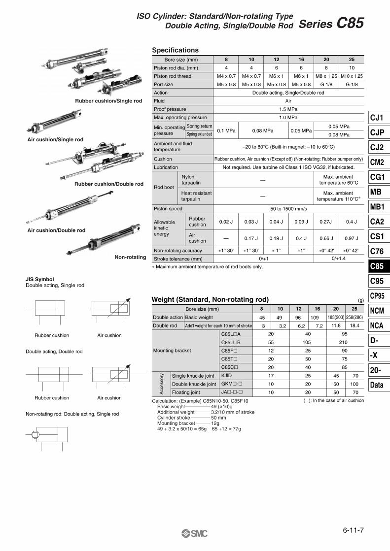
Series C85ISO Cylinder: Standard/Non-rotating Type
Double Acting, Single/Double Rod
SpecificationsBore size (mm) 8
4
M4 x 0.7
M5 x 0.8
10
4
M4 x 0.7
M5 x 0.8
12
6
M6 x 1
M5 x 0.8
16
6
M6 x 1
M5 x 0.8
20
8
M8 x 1.25
G 1/8
25
10
M10 x 1.25
G 1/8
Double acting, Single/Double rod
Air
1.5 MPa
1.0 MPa
0.1 MPa 0.08 MPa
—
—
–20 to 80°C (Built-in magnet: –10 to 60°C)
50 to 1500 mm/s
0.02 J 0.03 J 0.04 J 0.09 J 0.27J 0.4 J
— 0.17 J 0.19 J 0.4 J
±1° 30' ±1° 30' ± 1°
0/+1
±1°
0.66 J 0.97 J
±0° 42' ±0° 42'
0/+1.4
Rubber cushion, Air cushion (Except ø8) (Non-rotating: Rubber bumper only)
Not required. Use turbine oil Class 1 ISO VG32, if lubricated.
0.05 MPa0.05 MPa
0.08 MPa
Max. ambient temperature 60°C
Max. ambient temperature 110°C∗
Min. operating pressure
Spring return
Spring extended
Cushion
Lubrication
Ambient and fluid temperature
Rod boot
Piston speed
Non-rotating accuracy
Stroke tolerance (mm)
Allowablekineticenergy
Nylon tarpaulin
Heat resistant tarpaulin
Rubbercushion
Aircushion
∗ Maximum ambient temperature of rod boots only.
Weight (Standard, Non-rotating rod)
Double action
Double rod
Bore size (mm)
Single knuckle joint
Double knuckle joint
Floating joint
Mounting bracket
Acc
esso
ry
C85L�A
C85L�B
C85F�
C85T�
C85C�
KJlD
GKM�-�
JA�-�-�
25
258(286)
18.4
20
183(203)
11.8
1612108
20
55
12
20
20
17
10
10
40
105
25
50
40
25
20
20
95
210
90
75
85
45
50
50
70
100
70
Basic weight
Add’l weight for each 10 mm of stroke
(g)
JIS SymbolDouble acting, Single rod
Rubber cushion Air cushion
Rubber cushion Air cushion
Double acting, Double rod
Non-rotating rod: Double acting, Single rod
( ): In the case of air cushion
Rubber cushion/Single rod
Air cushion/Single rod
Rubber cushion/Double rod
Air cushion/Double rod
Non-rotating
Calculation: (Example) C85N10-50, C85F10Basic weight 49 (ø10)gAdditional weight 3.2/10 mm of strokeCylinder stroke 50 mmMounting bracket 12g49 + 3.2 x 50/10 = 65g 65 +12 = 77g
Piston rod dia. (mm)
Piston rod thread
Port size
Action
Fluid
Proof pressure
Max. operating pressure
45
3
49
3.2
96
6.2
109
7.2
6-11-8
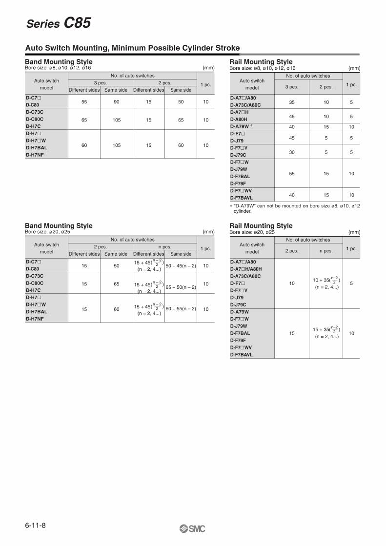
Series C85
Band Mounting Style
Auto Switch Mounting, Minimum Possible Cylinder Stroke
No. of auto switches
3 pcs. 2 pcs.
Different sides
55
65
60
Same side
90
105
105
Same side
50
65
60
15
15
15
1 pc.
10
10
10
Different sides
Auto switch
model
D-C7�D-C80D-C73CD-C80CD-H7C D-H7�D-H7�WD-H7BALD-H7NF
(mm)Bore size: ø8, ø10, ø12, ø16
35
45
40
45
30
55
40
10
10
15
5
5
15
15
5
5
10
5
5
10
10
Rail Mounting Style
No. of auto switches
3 pcs. 2 pcs.Auto switch
model
D-A7�/A80D-A73C/A80CD-A7�HD-A80HD-A79W ∗
D-F7�D-J79D-F7�VD-J79CD-F7�WD-J79WD-F7BALD-F79FD-F7�WVD-F7BAVL
1 pc.
(mm)Bore size: ø8, ø10, ø12, ø16
Band Mounting Style
No. of auto switches
2 pcs. n pcs.
Different sides
15
15
15
Same side
50
65
60
Same side1 pc.
10
10
10
Different sides
Auto switch
model
D-C7�D-C80D-C73CD-C80CD-H7C D-H7�D-H7�WD-H7BALD-H7NF
(mm)Bore size: ø20, ø25Rail Mounting Style
No. of auto switches
2 pcs. n pcs.Auto switch
model
D-A7�/A80D-A7�H/A80HD-A73C/A80CD-F7�D-F7�VD-J79D-J79CD-A79WD-F7�WD-J79WD-F7BALD-F79FD-F7�WVD-F7BAVL
1 pc.
(mm)Bore size: ø20, ø25
50 + 45(n – 2)
65 + 50(n – 2)
60 + 55(n – 2)
15 + 45(n = 2, 4...)
( n – 2 )2
15 + 45(n = 2, 4...)
( n – 2 )2
15 + 45(n = 2, 4...)
( n – 2 )2
)10 + 35(n = 2, 4...)
( n–22
)15 + 35(n = 2, 4...)
( n–22
10
15
5
10
∗ “D-A79W” can not be mounted on bore size ø8, ø10, ø12 cylinder.
6-11-9
CJ1
CJP
CJ2
CM2
CG1
MB
MB1
CA2
CS1
C76
C85
C95
CP95
NCM
NCA
D-
-X
20-
Data
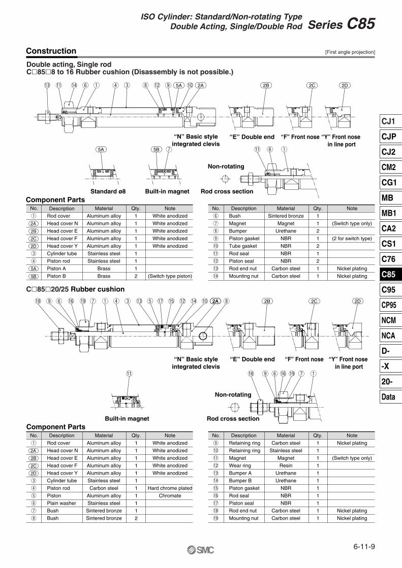
Series C85ISO Cylinder: Standard/Non-rotating Type
Double Acting, Single/Double Rod
2A
No.
Rod cover
Head cover N
Head cover E
Head cover F
Head cover Y
Cylinder tube
Piston rod
Piston A
Piston B
Material
Aluminum alloy
Aluminum alloy
Aluminum alloy
Aluminum alloy
Aluminum alloy
Stainless steel
Stainless steel
Brass
Brass
1
1
1
1
1
1
1
1
2
Note
White anodized
White anodized
White anodized
White anodized
White anodized
(Switch type piston)
Component Parts
2A
2B
2C
2D
5A
5B
Double acting, Single rodC�85�8 to 16 Rubber cushion (Disassembly is not possible.)
Description Qty.
q
e
r
No.
Bush
Magnet
Bumper
Piston gasket
Tube gasket
Rod seal
Piston seal
Rod end nut
Mounting nut
Material
Sintered bronze
Magnet
Urethane
NBR
NBR
NBR
NBR
Carbon steel
Carbon steel
1
1
2
1
2
1
2
1
1
Note
(Switch type only)
(2 for switch type)
Nickel plating
Nickel plating
Description Qty.
y
u
i
o
!0
!1
!2
!3
!4
No.
Rod cover
Head cover N
Head cover E
Head cover F
Head cover Y
Cylinder tube
Piston rod
Piston
Plain washer
Bush
Bush
Material
Aluminum alloy
Aluminum alloy
Aluminum alloy
Aluminum alloy
Aluminum alloy
Stainless steel
Carbon steel
Aluminum alloy
Stainless steel
Sintered bronze
Sintered bronze
1
1
1
1
1
1
1
1
1
1
2
Note
White anodized
White anodized
White anodized
White anodized
White anodized
Hard chrome plated
Chromate
Component Parts
2A
2B
2C
2D
Description Qty.
q
e
r
t
y
u
i
No.
Retaining ring
Retaining ring
Magnet
Wear ring
Bumper A
Bumper B
Piston gasket
Rod seal
Piston seal
Rod end nut
Mounting nut
Material
Carbon steel
Stainless steel
Magnet
Resin
Urethane
Urethane
NBR
NBR
NBR
Carbon steel
Carbon steel
1
1
1
1
1
1
1
1
1
1
1
Note
Nickel plating
(Switch type only)
Nickel plating
Nickel plating
Description Qty.
o
!0
!1
!2
!3
!4
!5
!6
!7
!8
!9
C�85�20/25 Rubber cushion
!3 !1 !4 y q r e i
u
!2 o !0
!1 y q
!8 2Ao y !6 !9 u q r e !3 t !7 !5 !2 !4 i!0
!1 !8 o y !6 !9 u q
“Y” Front nose in line port
“N” Basic styleintegrated clevis
“E” Double end “F” Front nose
Non-rotating
Rod cross sectionBuilt-in magnetStandard ø8
“F” Front nose “N” Basic styleintegrated clevis
“E” Double end “Y” Front nose in line port
Non-rotating
Rod cross sectionBuilt-in magnet
2B 2C 2D
5A 2A 2B 2C 2D
5A 5B
Construction [First angle projection]
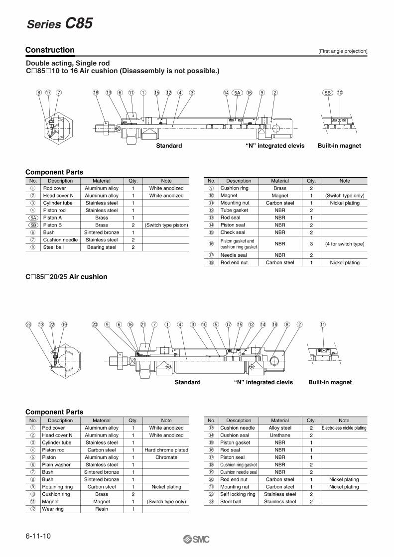
6-11-10
Series C85
Construction
Double acting, Single rodC�85�10 to 16 Air cushion (Disassembly is not possible.)
No.
Rod cover
Head cover N
Cylinder tube
Piston rod
Piston A
Piston B
Bush
Cushion needle
Steel ball
Material
Aluminum alloy
Aluminum alloy
Stainless steel
Stainless steel
Brass
Brass
Sintered bronze
Stainless steel
Bearing steel
1
1
1
1
1
2
1
2
2
Note
White anodized
White anodized
(Switch type piston)
Component Parts
5A
5B
Description Qty.
q
w
e
r
y
u
i
No.
Cushion ring
Magnet
Mounting nut
Tube gasket
Rod seal
Piston seal
Check seal
Piston gasket andcushion ring gasket
Needle seal
Rod end nut
Material
Brass
Magnet
Carbon steel
NBR
NBR
NBR
NBR
NBR
NBR
Carbon steel
2
1
1
2
1
2
2
3
2
1
Note
(Switch type only)
Nickel plating
(4 for switch type)
Nickel plating
Description Qty.
o
!0
!11
!2
!3
!4
!5
!6
!7
!8
No.
Rod cover
Head cover N
Cylinder tube
Piston rod
Piston
Plain washer
Bush
Bush
Retaining ring
Cushion ring
Magnet
Wear ring
Material
Aluminum alloy
Aluminum alloy
Stainless steel
Carbon steel
Aluminum alloy
Stainless steel
Sintered bronze
Sintered bronze
Carbon steel
Brass
Magnet
Resin
1
1
1
1
1
1
1
1
1
2
1
1
Note
White anodized
White anodized
Hard chrome plated
Chromate
Nickel plating
(Switch type only)
Component PartsDescription Qty.
q
w
e
r
t
y
u
i
o
!0
!1
!2
No.
Cushion needle
Cushion seal
Piston gasket
Rod seal
Piston seal
Cushion ring gasket
Cushion needle seal
Rod end nut
Mounting nut
Self locking ring
Steel ball
Material
Alloy steel
Urethane
NBR
NBR
NBR
NBR
NBR
Carbon steel
Carbon steel
Stainless steel
Stainless steel
2
2
1
1
1
2
2
1
1
2
2
Note
Electroless nickle plating
Nickel plating
Nickel plating
Description Qty.
!3
!4
!5
!6
!7
!8
!9
@0
@1
@2
@3
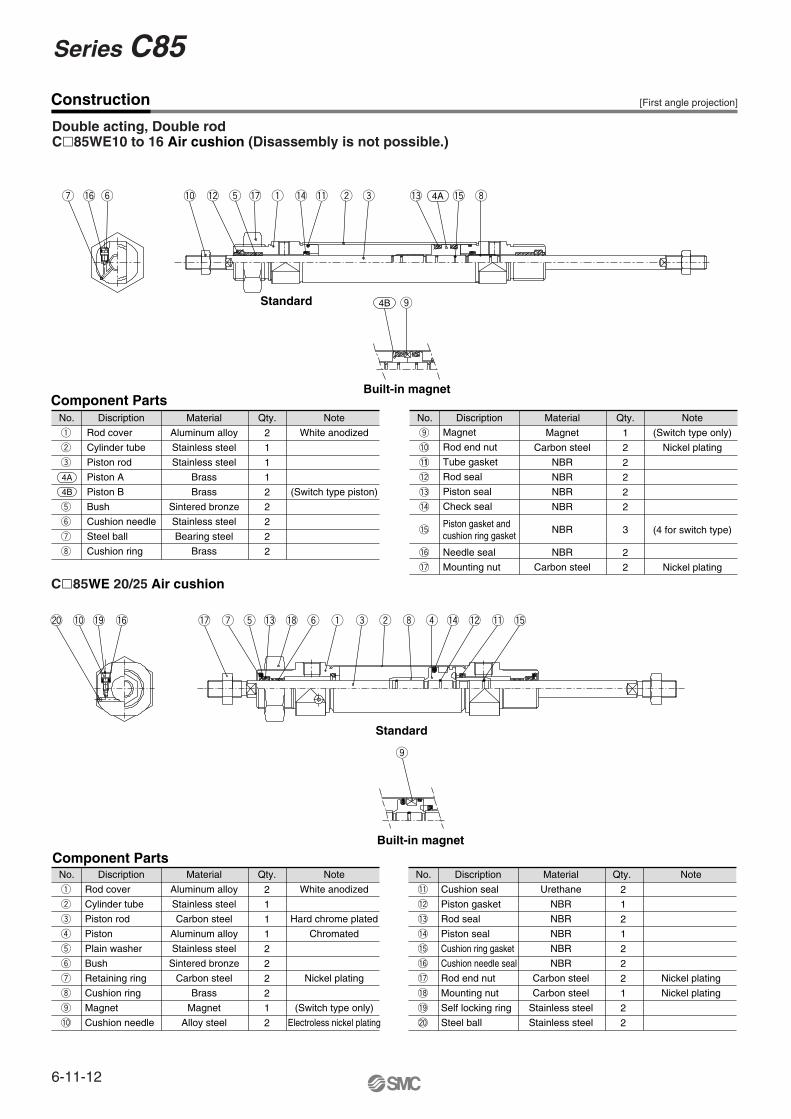
C�85�20/25 Air cushion
i !7 u !8 !3 y !1 q !5 !2 r e !4 !65A 5Bo !0w
@3 !3 @2 !9 @0 o y !6 @1 u q r e !0 t !7 !5 !2 !4 !8 i w !1
Standard “N” integrated clevis Built-in magnet
Built-in magnet“N” integrated clevisStandard
[First angle projection]
6-11-11
CJ1
CJP
CJ2
CM2
CG1
MB
MB1
CA2
CS1
C76
C85
C95
CP95
NCM
NCA
D-
-X
20-
Data
Series C85ISO Cylinder: Standard/Non-rotating Type
Double Acting, Single/Double Rod
Construction
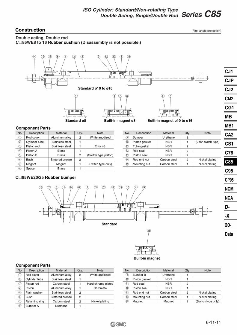
Double acting, Double rodC�85WE8 to 16 Rubber cushion (Disassembly is not possible.)
No.
Rod cover
Cylinder tube
Piston rod
Piston A
Piston B
Bush
Magnet
Spacer
Material
Aluminum alloy
Stainless steel
Stainless steel
Brass
Brass
Sintered bronze
Magnet
Brass
2
1
1
1
2
2
1
1
Note
White anodized
2 for ø8
(Switch type piston)
(Switch type only)
Component PartsDescription Qty.
q
w
e
r
t
y
u
i
No.
Bumper
Piston gasket
Tube gasket
Rod seal
Piston seal
Rod end nut
Mounting nut
Material
Urethane
NBR
NBR
NBR
NBR
Carbon steel
Carbon steel
2
1
2
2
2
2
1
Note
(2 for switch type)
Nickel plating
Nickel plating
Description Qty.
o
!0
!11
!2
!3
!4
!5
No.
Rod cover
Cylinder tube
Piston rod
Piston
Plain washer
Bush
Retaining ring
Bumper A
Material
Aluminum alloy
Stainless steel
Carbon steel
Aluminum alloy
Stainless steel
Sintered bronze
Carbon steel
Urethane
2
1
1
1
2
2
2
1
Note
White anodized
Hard chrome plated
Chromate
Nickel plating
Component PartsDescription Qty.
q
w
e
r
t
y
u
i
No.
Bumper B
Piston gasket
Rod seal
Piston seal
Rod end nut
Mounting nut
Magnet
Material
Urethane
NBR
NBR
NBR
Carbon steel
Carbon steel
Magnet
1
1
2
1
2
1
1
Note
Nickel plating
Nickel plating
(Switch type only)
Description Qty.
o
!0
!1
!2
!3
!4
!5
C�85WE20/25 Rubber bumper
!4 !2 !5 y q e w o !3 !0 r !1
r r u i t u
!3 u t !1 !4 y q e w i !2 !0 r o
!5
Standard ø10 to ø16
Standard ø8 Built-in magnet ø8 Built-in magnet ø10 to ø16
Standard
Built-in magnet
[First angle projection]
6-11-12
Series C85
Construction
Double acting, Double rodC�85WE10 to 16 Air cushion (Disassembly is not possible.)
No.
Rod cover
Cylinder tube
Piston rod
Piston A
Piston B
Bush
Cushion needle
Steel ball
Cushion ring
Material
Aluminum alloy
Stainless steel
Stainless steel
Brass
Brass
Sintered bronze
Stainless steel
Bearing steel
Brass
2
1
1
1
2
2
2
2
2
Note
White anodized
(Switch type piston)
Component PartsDiscription Qty.
q
w
e
t
y
u
i
No.
Magnet
Rod end nut
Tube gasket
Rod seal
Piston seal
Check seal
Piston gasket andcushion ring gasket
Needle seal
Mounting nut
Material
Magnet
Carbon steel
NBR
NBR
NBR
NBR
NBR
NBR
Carbon steel
1
2
2
2
2
2
3
2
2
Note
(Switch type only)
Nickel plating
(4 for switch type)
Nickel plating
Discription Qty.
o
!0
!11
!2
!3
!4
!5
!6
!7
No.
Rod cover
Cylinder tube
Piston rod
Piston
Plain washer
Bush
Retaining ring
Cushion ring
Magnet
Cushion needle
Material
Aluminum alloy
Stainless steel
Carbon steel
Aluminum alloy
Stainless steel
Sintered bronze
Carbon steel
Brass
Magnet
Alloy steel
2
1
1
1
2
2
2
2
1
2
Note
White anodized
Hard chrome plated
Chromated
Nickel plating
(Switch type only)
Electroless nickel plating
Component PartsDiscription Qty.
q
w
e
r
t
y
u
i
o
!0
No.
Cushion seal
Piston gasket
Rod seal
Piston seal
Cushion ring gasket
Cushion needle seal
Rod end nut
Mounting nut
Self locking ring
Steel ball
Material
Urethane
NBR
NBR
NBR
NBR
NBR
Carbon steel
Carbon steel
Stainless steel
Stainless steel
2
1
2
1
2
2
2
1
2
2
Note
Nickel plating
Nickel plating
Discription Qty.
!1
!2
!3
!4
!5
!6
!7
!8
!9
@0
C�85WE 20/25 Air cushion
4A
4B
4Au !6 y !0 !2 t !7 q !4 !1 w e !3 !5 i
4B o
@0 !0 !9 !6 !7 u t !3 !8 y q e w i r !4 !2 !1 !5
o
Built-in magnet
Standard
Standard
Built-in magnet
[First angle projection]
6-11-13
CJ1
CJP
CJ2
CM2
CG1
MB
MB1
CA2
CS1
C76
C85
C95
CP95
NCM
NCA
D-
-X
20-
Data
Series C85ISO Cylinder: Standard/Non-rotating Type
Double Acting, Single/Double Rod
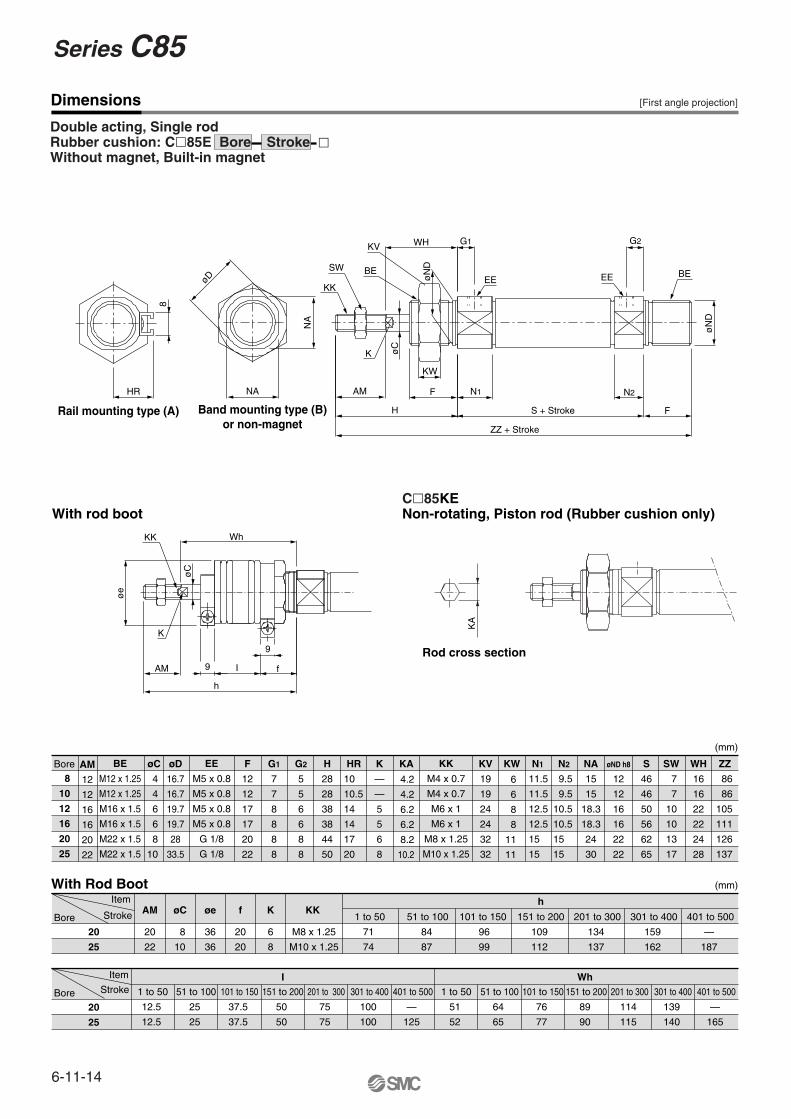
Bore øCAM
12
12
16
16
20
22
Bore
Bore
20
25
20
25
AM øC øe f K
20
22
8
10
36
36
20
20
6
8
KK1 to 50
M8 x 1.25
M10 x 1.25
71
74
1 to 50
12.5
12.5
51 to 100
25
25
101 to 150
37.5
37.5
151 to 200
50
50
201 to 300
75
75
301 to 400
100
100
401 to 500
—
125
1 to 50
51
52
51 to 100
64
65
101 to 150
76
77
151 to 200
89
90
201 to 300
114
115
301 to 400
139
140
401 to 500
—
165
51 to 100
84
87
101 to 150
96
99
151 to 200
h
WhI
109
112
201 to 300
134
137
301 to 400
159
162
401 to 500
(mm)
(mm)
—
187
Stroke
Stroke
Item
Item
øCD H9 øD EW F
12
12
17
17
20
22
G1
7
8
8
G2
5
8
8
WA
—
10.5
9.5
9.5
11.5(13)
11.5(13)
WB H
28
28
38
38
44
50
HR K
—
—
5
5
6
8
KA KV
19
19
24
24
32
32
KW NA
15
15
18.3
18.3
24
30
N2
9.5
15(17)
15(17)
N1
11.5
15(17)
15(17)
øND h8
12
12
16
16
22
22
RR
10
10
14
13
11
11
KK
M4 x 0.7
M4 x 0.7
M6 x 1
M6 x 1
M8 x 1.25
M10 x 1.25
EE
M5 x 0.8
M5 x 0.8
M5 x 0.8
M5 x 0.8
G 1/8
G 1/8
BE
M12 x 1.25
M12 x 1.25
M16 x 1.5
M16 x 1.5
M22 x 1.5
M22 x 1.5
U WH
16
16
22
22
24
28
XC
64
95
104
Z
76
115
126
ZZ
86
126
137
SWS
46
62
65
4H9
4H9
6H9
6H9
8
7(5.5)
8(5.5)
8(5.5)
5(5.5)
11.5(13.5)12.5
(12.5)12.5
(12.5)
9.5(13.5)
46(53)
64(71)75
(79)82
(82)
76(83)91
(95)98
(98)
86(93)105
(109)111
(111)
50(54)56
(56)
10.5(12.5)10.5
(12.5)
6(5.5)
6(5.5)
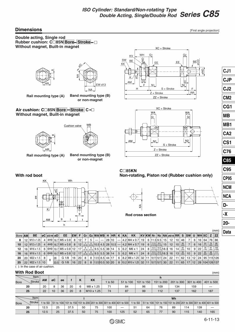
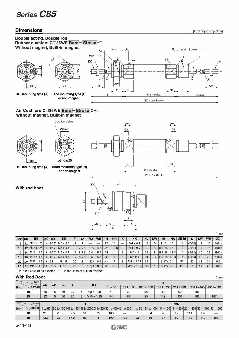
( ): In the case of air cushion.
With Rod Boot
Air cushion: C�85N Bore Stroke C �Without magnet, Built-in magnet
With rod bootC�85KNNon-rotating, Piston rod (Rubber cushion only)
Band mounting type (B)or non-magnet
Band mounting type (B)or non-magnet
Rod cross section
NA
NA
øD
EW d13
SWKK
BE
KV WH
K
G1
EE
øC
AM
HF
KW
N1
ZZ + Stroke
Z + Stroke
S + Stroke
RRF
UN2
øN
D
øC
D
øN
D
BE
G2
EE
XC + Stroke
Cushion valve WB
AM N1S + Stroke
Z + Stroke
ZZ + Stroke
N2
WA
G2
XC + Stroke
WA
G1
KA
øe
KK
øC
K
AM
h
9
9
I f
Wh
Dimensions
Rail mounting type (A)
8
HR
Rail mounting type (A)
8
HR
Double acting, Single rodRubber cushion: C�85N Bore Stroke �Without magnet, Built-in magnet
6
6
9
9
12
12
7
7
10
10
13
17
6
6
8
8
11
11
4.2
4.2
6.2
6.2
8.2
10.2
10
10.5
14
14
17
20
—
4.5
5.5
5.5
8.5
10.5
8
8
12
12
16
16
16.7
16.7
19.7
19.7
28
33.5
4
4
6
6
8
10
8
10
12
16
20
25
[First angle projection]
6-11-14
Series C85
Dimensions
8
10
12
16
20
25
øCAM
12
12
16
16
20
22
Bore
Bore
20
25
20
25
AM øC øe f K
20
22
8
10
36
36
20
20
6
8
KK1 to 50
M8 x 1.25
M10 x 1.25
71
74
1 to 50
12.5
12.5
51 to 100
25
25
101 to 150
37.5
37.5
151 to 200
50
50
201 to 300
75
75
301 to 400
100
100
401 to 500
—
125
1 to 50
51
52
51 to 100
64
65
101 to 150
76
77
151 to 200
89
90
201 to 300
114
115
301 to 400
139
140
401 to 500
—
165
51 to 100
84
87
101 to 150
96
99
151 to 200
h
WhI
109
112
201 to 300
134
137
301 to 400
159
162
401 to 500
—
187
Stroke
Stroke
Item
Item
øD
16.7
16.7
19.7
19.7
28
33.5
F
12
12
17
17
20
22
G1
7
7
8
8
8
8
G2
5
5
6
6
8
8
H
28
28
38
38
44
50
HR K
—
—
5
5
6
8
KA KV
19
19
24
24
32
32
KW NA
15
15
18.3
18.3
24
30
N2N1 øND h8
12
12
16
16
22
22
KK
M4 x 0.7
M4 x 0.7
M6 x 1
M6 x 1
M8 x 1.25
M10 x 1.25
EE
M5 x 0.8
M5 x 0.8
M5 x 0.8
M5 x 0.8
G 1/8
G 1/8
BE
M12 x 1.25
M12 x 1.25
M16 x 1.5
M16 x 1.5
M22 x 1.5
M22 x 1.5
WH
16
16
22
22
24
28
ZZSWS
46
46
50
56
62
65
With Rod Boot
With rod boot
Rod cross section
KA
øe
KK
øC
K
AM
h
9
9
I f
Wh
8
HR NA
NA
øD
SW
KK
AM
K øC
H
F
KW
N1
ZZ + Stroke
S + Stroke
KV
BE
WH
øN
D
G1
EE
N2
F
øN
D
BE
G2
EE
Rail mounting type (A) Band mounting type (B)or non-magnet
C�85KENon-rotating, Piston rod (Rubber cushion only)
Double acting, Single rodRubber cushion: C�85E Bore Stroke �Without magnet, Built-in magnet
Bore
4
4
6
6
8
10
10
10.5
14
14
17
20
4.2
4.2
6.2
6.2
8.2
10.2
6
6
8
8
11
11
11.5
11.5
12.5
12.5
15
15
9.5
9.5
10.5
10.5
15
15
7
7
10
10
13
17
86
86
105
111
126
137
[First angle projection]
(mm)
(mm)
6-11-15
CJ1
CJP
CJ2
CM2
CG1
MB
MB1
CA2
CS1
C76
C85
C95
CP95
NCM
NCA
D-
-X
20-
Data
Series C85ISO Cylinder: Standard/Non-rotating Type
Double Acting, Single/Double Rod
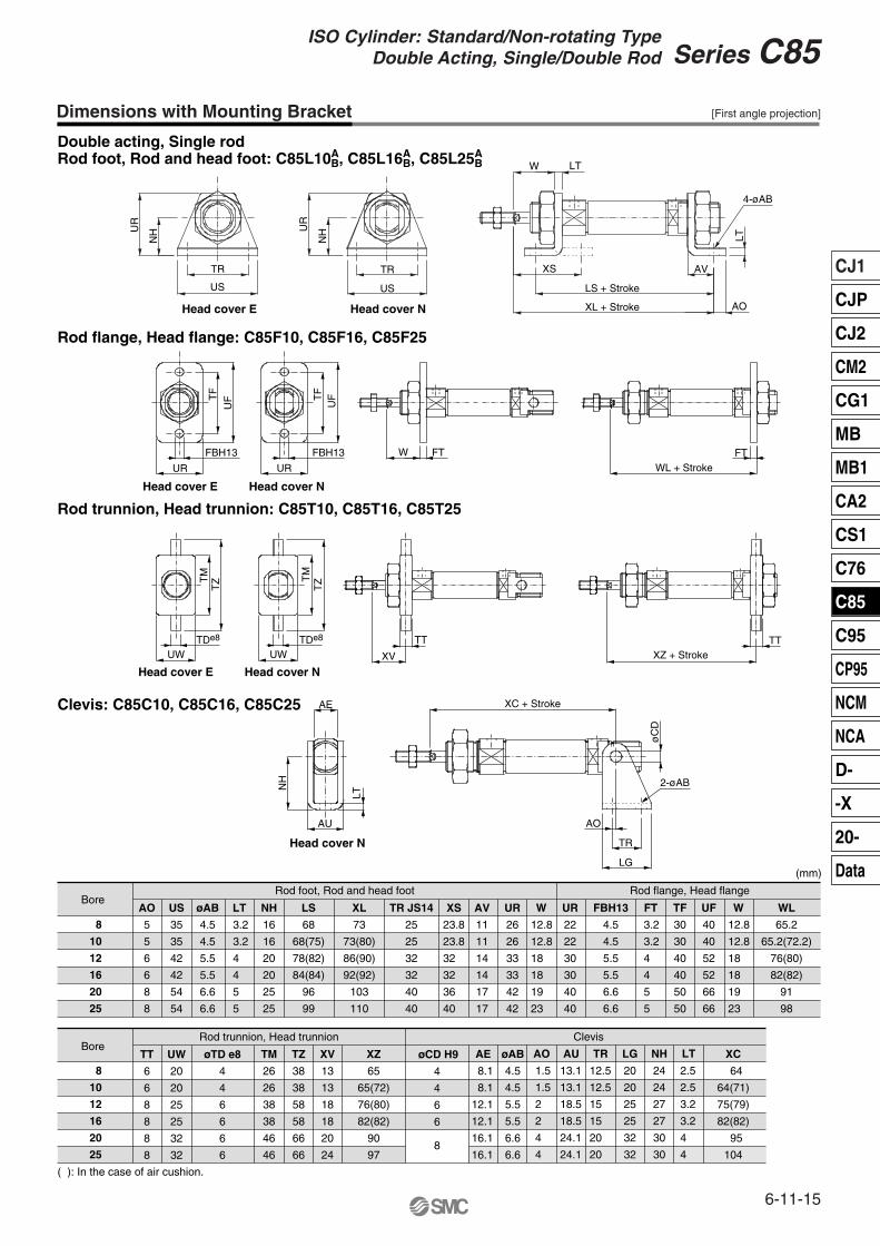
Dimensions with Mounting Bracket
8
10
12
16
20
25
Double acting, Single rodRod foot, Rod and head foot: C85L10A
B, C85L16AB, C85L25A
B
Rod flange, Head flange: C85F10, C85F16, C85F25
Rod trunnion, Head trunnion: C85T10, C85T16, C85T25
Clevis: C85C10, C85C16, C85C25
Bore AO
5
5
6
6
8
8
US
35
35
42
42
54
54
øAB
4.5
4.5
5.5
5.5
6.6
6.6
LT NH
16
16
20
20
25
25
LS
68
68(75)
78(82)
84(84)
96
99
XL
73
73(80)
86(90)
92(92)
103
110
TR JS14
25
25
32
32
40
40
XS AV
11
11
14
14
17
17
UR
26
26
33
33
42
42
W UR
22
22
30
30
40
40
FBH13
4.5
4.5
5.5
5.5
6.6
6.6
FT TF
30
30
40
40
50
50
Rod flange, Head flangeRod foot, Rod and head foot
UF
40
40
52
52
66
66
W WL
65.2
65.2(72.2)
76(80)
82(82)
91
98
8
10
12
16
20
25
TT
6
6
8
8
8
8
UW
20
20
25
25
32
32
øTD e8
4
4
6
6
6
6
TM
26
26
38
38
46
46
TZ
38
38
58
58
66
66
XV
13
13
18
18
20
24
XZ
65
65(72)
76(80)
82(82)
90
97
øCD H9
4
4
6
6
AE øAB
4.5
4.5
5.5
5.5
6.6
6.6
AO AU TR LG
20
20
25
25
32
32
NH
24
24
27
27
30
30
LT XC
64
64(71)
75(79)
82(82)
95
104
( ): In the case of air cushion.
UR
NH
TR
US
UR
NH
TR
US
W LT
XS
LS + Stroke
XL + Stroke
AV
AO
LT
4-øABT
F
UF
FBH13
UR UR
FBH13
TF
UF
W FT
WL + StrokeFT
TM
TZ
TDe8 TDe8
UW UW
TM
TZ
XV
TT
XZ + StrokeTT
XC + Stroke
øC
D
2-øAB
LG
TR
AO
AE
NH
LT
AU
Head cover E Head cover N
Head cover E Head cover N
Head cover E Head cover N
Head cover N
Rod trunnion, Head trunnion Clevis
8
Bore
3.2
3.2
4
4
5
5
23.8
23.8
32
32
36
40
12.8
12.8
18
18
19
23
12.8
12.8
18
18
19
23
3.2
3.2
4
4
5
5
2.5
2.5
3.2
3.2
4
4
12.5
12.5
15
15
20
20
1.5
1.5
2
2
4
4
8.1
8.1
12.1
12.1
16.1
16.1
13.1
13.1
18.5
18.5
24.1
24.1
[First angle projection]
(mm)
6-11-16
Series C85
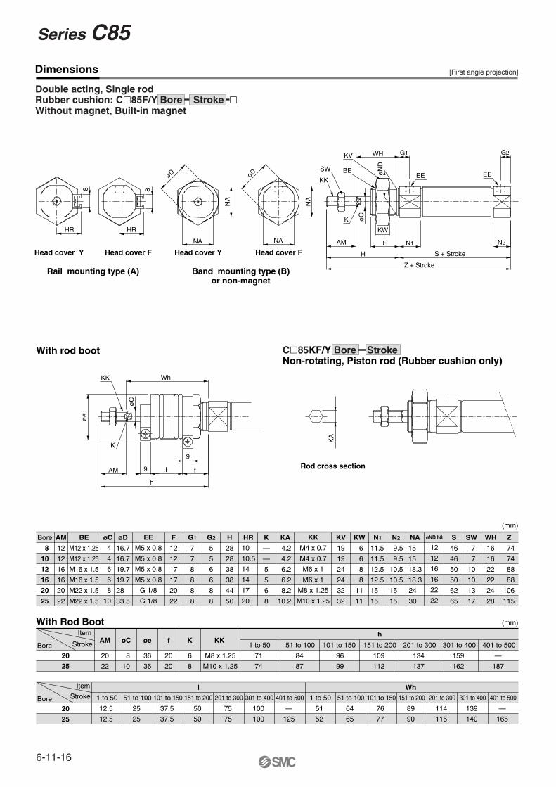
Dimensions
Bore øCAM
12
12
16
16
20
22
20
25
20
25
AM øC øe f K
20
22
8
10
36
36
20
20
6
8
KK1 to 50
M8 x 1.25
M10 x 1.25
71
74
1 to 50
12.5
12.5
51 to 100
25
25
101 to 150
37.5
37.5
151 to 200
50
50
201 to 300
75
75
301 to 400
100
100
401 to 500
—
125
1 to 50
51
52
51 to 100
64
65
101 to 150
76
77
151 to 200
89
90
201 to 300
114
115
301 to 400
139
140
401 to 500
—
165
51 to 100
84
87
101 to 150
96
99
151 to 200
h
WhI
109
112
201 to 300
134
137
301 to 400
159
162
401 to 500
—
187
Stroke
Bore
Bore
Stroke
Item
Item
øD
16.7
16.7
19.7
19.7
28
33.5
F
12
12
17
17
20
22
G1
7
7
8
8
8
8
G2
5
5
6
6
8
8
H
28
28
38
38
44
50
HR K
—
—
5
5
6
8
KA KV
19
19
24
24
32
32
KW
6
6
8
8
11
11
NA
15
15
18.3
18.3
24
30
N2N1 øND h8
12
12
16
16
22
22
KK
M4 x 0.7
M4 x 0.7
M6 x 1
M6 x 1
M8 x 1.25
M10 x 1.25
EE
M5 x 0.8
M5 x 0.8
M5 x 0.8
M5 x 0.8
G 1/8
G 1/8
BE
M12 x 1.25
M12 x 1.25
M16 x 1.5
M16 x 1.5
M22 x 1.5
M22 x 1.5
WH
16
16
22
22
24
28
ZSWS
46
46
50
50
62
65
With Rod Boot
With rod boot C�85KF/Y Bore StrokeNon-rotating, Piston rod (Rubber cushion only)
Rod cross section
KA
øe
KK
øC
K
AM
h
9
9
I f
Wh
8 8
HR HR
øD øD
NA
NA
NA
NA
SW
KK
KV
BE
WH
øN
D
K
AM
øC
H
KW
F N1
Z + Stroke
S + Stroke
N2
G2
EE
G1
EE
Head cover Y
Rail mounting type (A) Band mounting type (B)or non-magnet
Double acting, Single rodRubber cushion: C�85F/Y Bore Stroke �Without magnet, Built-in magnet
Head cover F Head cover FHead cover Y
8
10
12
16
20
25
4
4
6
6
8
10
10
10.5
14
14
17
20
4.2
4.2
6.2
6.2
8.2
10.2
11.5
11.5
12.5
12.5
15
15
9.5
9.5
10.5
10.5
15
15
7
7
10
10
13
17
74
74
88
88
106
115
(mm)
(mm)
[First angle projection]
6-11-17
CJ1
CJP
CJ2
CM2
CG1
MB
MB1
CA2
CS1
C76
C85
C95
CP95
NCM
NCA
D-
-X
20-
Data
Series C85ISO Cylinder: Standard/Non-rotating Type
Double Acting, Single/Double Rod
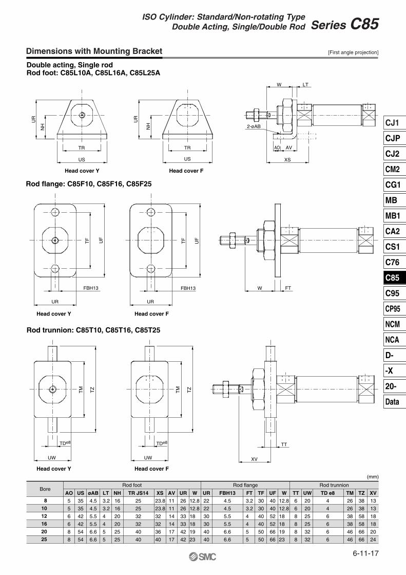
Dimensions with Mounting Bracket
Double acting, Single rodRod foot: C85L10A, C85L16A, C85L25A
8
10
12
16
20
25
Rod flange: C85F10, C85F16, C85F25
Rod trunnion: C85T10, C85T16, C85T25
BoreAO
5
5
6
6
8
8
US
35
35
42
42
54
54
øAB
4.5
4.5
5.5
5.5
6.6
6.6
LT NH
16
16
20
20
25
25
TR JS14
25
25
32
32
40
40
XS AV
11
11
14
14
17
17
UR
26
26
33
33
42
42
W UR
22
22
30
30
40
40
FBH13
4.5
4.5
5.5
5.5
6.6
6.6
FT TF
30
30
40
40
50
50
UF
40
40
52
52
66
66
W TT
6
6
8
8
8
8
UW
20
20
25
25
32
32
TD e8
4
4
6
6
6
6
TM
26
26
38
38
46
46
TZ
38
38
58
58
66
66
XV
13
13
18
18
20
24
Rod trunnionRod flangeRod foot
Head cover Y
Head cover Y
Head cover F
Head cover F
Head cover Y Head cover F
UR
NH
TR
US
UR
NH
TR
US
2-øAB
XS
AO AV
W LT
W FTFBH13
UR
TF
UF
TF UF
FBH13
UR
UW
TDe8
UW
TDe8
TM TZ
TM TZ
XV
TT
3.2
3.2
4
4
5
5
23.8
23.8
32
32
36
40
12.8
12.8
18
18
19
23
3.2
3.2
4
4
5
5
12.8
12.8
18
18
19
23
[First angle projection]
(mm)
Dimensions
Double acting, Double rodRubber cushion: C�85WE Bore Stroke � Without magnet, Built-in magnet
Bore øCAM
12
12
16
16
20
22
Bore
Bore
20
25
20
25
AM øC øe f K
20
22
8
10
36
36
20
20
6
8
KK1 to 50
M8 x 1.25
M10 x 1.25
71
74
1 to 50
12.5
12.5
50 to 100
25
25
101 to 150
37.5
37.5
151 to 200
50
50
201 to 300
75
75
301 to 400
100
100
401 to 500 1 to 50
51
52
51 to 100
64
65
101 ~ 150
76
77
151 ~ 200
89
90
201 ~ 300
114
115
301 ~ 400
139
140
401 ~ 500
—
165
51 to 100
84
87
101 to 150
96
99
151 to 200
h
WhI
109
112
201 to 300
134
137
301 to 400
159
162
401 to 500
—
187
Stroke
Stroke
Item
Item
øD F
12
12
17
17
20
22
G1
7
7(5.5)
8(5.5)
8(5.5)
8
8
WA
—
10.5
9.5
9.5
11.5(13)
11.5(13)
WB
—
H
28
28
38
38
44
50
HR K
—
—
5
5
6
8
KV
19
19
24
24
32
32
KW NA
15
15
18.3
18.3
24
30
N1
11.5
11.5(13.5)
12.5(12.5)
12.5(12.5)
15(17)
15(17)
øND h8
12
12
16
16
22
22
KK
M4 x 0.7
M4 x 0.7
M6 x 1
M6 x 1
M8 x 1.25
M10 x 1.25
EE
M5 x 0.8
M5 x 0.8
M5 x 0.8
M5 x 0.8
G 1/8
G 1/8
BE
M12 x 1.25
M12 x 1.25
M16 x 1.5
M16 x 1.5
M22 x 1.5
M22 x 1.5
WH
16
16
22
22
24
28
ZZ
104{110}
104(109)
128(130)
128(130)
150
165
SWS
48{54}
48(53)
52(54)
52(54)
62
65
With Rod Boot
With rod boot
øe
KK
øC
K
AMh
9
9
I f
Wh
( ): In the case of air cushion. { }: In the case of built-in magnet
Rail mounting type (A) Band mounting type (B)or non-magnet
Rail mounting type (A)
ø8 to ø25
8
HR
øD
NA
NA
H
AM
K øC
KW
F N1
S + Stroke
ZZ + 2 x Stroke
N1 F
H + Stroke
øC
K
AM
KK
BE
øN
D
WH + StrokeG1
EE
8
HR
Cushion Valve
WBWB
N1
ZZ + 2 x Stroke
S + Stroke
N1
G1
WAWA
G1
KK
SW BE
KV WH G1
EE
øND
Air Cushion: C�85WE Bore Stroke C �Without magnet, Built-in magnet
Band mounting type (B)or non-magnet
7
7
10
10
13
17
6
6
8
8
11
11
10
10.5
14
14
17
20
4.5
5.5
5.5
8.5
10.5
16.7
16.7
19.7
19.7
28
33.5
4
4
6
6
8
10
8
10
12
16
20
25
[First angle projection]
(mm)
(mm)
—
125
6-11-18
Series C85
6-11-18
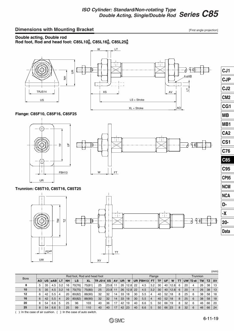
Dimensions with Mounting Bracket
Double acting, Double rodRod foot, Rod and head foot: C85L10A
B, C85L16AB, C85L25A
B
8
10
12
16
20
25
Flange: C85F10, C85F16, C85F25
Trunnion: C85T10, C85T16, C85T25
BoreAO
5
5
6
6
8
8
US
35
35
42
42
54
54
øAB
4.5
4.5
5.5
5.5
6.6
6.6
LT NH
16
16
20
20
25
25
LS
70{76}
70(75)
80(82)
80(82)
96
99
XL
75{81}
75(80)
88(90)
88(90)
103
110
XSTR JS14
25
25
32
32
40
40
AV
11
11
14
14
17
17
UR
26
26
33
33
42
42
W UR
22
22
30
30
40
40
FBH13
4.5
4.5
5.5
5.5
6.6
6.6
FT TF
30
30
40
40
50
50
UF
40
40
52
52
66
66
W TT
6
6
8
8
8
8
UW
20
20
25
25
32
32
TD e8
4
4
6
6
6
6
TM
26
26
38
38
46
46
TZ
38
38
58
58
66
66
XV
13
13
18
18
20
24
TrunnionFlangeRod foot, Rod and head foot
( ): In the case of air cushion. { }: In the case of auto switch.
TRJS14
US
NH
UR
XS
LS + Stroke
XL + Stroke
AV
AO
LT
4-øAB
LTW
UR
FBH13
TF
UF
W FT
TT
XV
TZ
TM
FDe8
UW
3.2
3.2
4
4
5
5
23.8
23.8
32
32
36
40
12.8
12.8
18
18
19
23
3.2
3.2
4
4
5
5
12.8
12.8
18
18
19
23
[First angle projection]
(mm)
6-11-19
CJ1
CJP
CJ2
CM2
CG1
MB
MB1
CA2
CS1
C76
C85
C95
CP95
NCM
NCA
D-
-X
20-
Data
Series C85ISO Cylinder: Standard/Non-rotating Type
Double Acting, Single/Double Rod
6-11-19
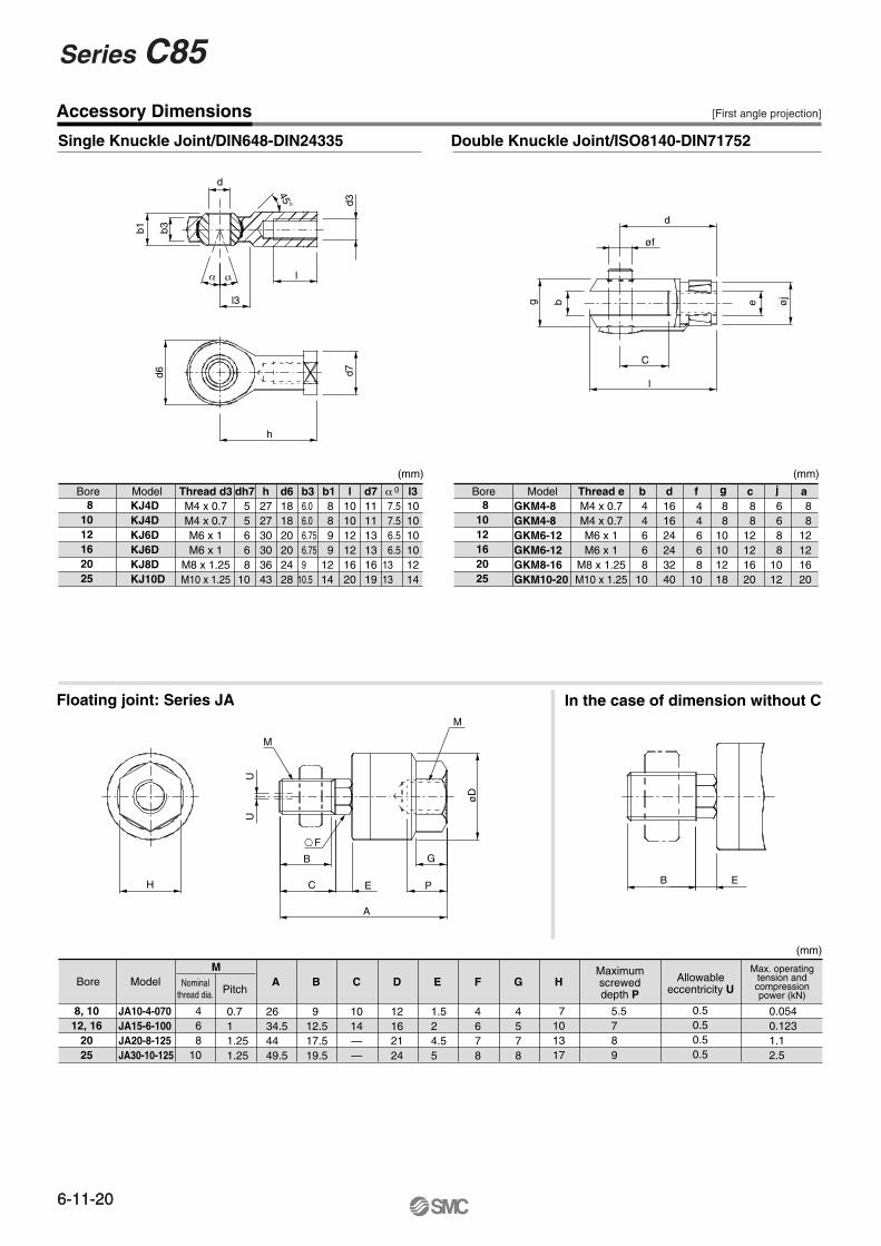
Accessory Dimensions
Single Knuckle Joint/DIN648-DIN24335 Double Knuckle Joint/ISO8140-DIN71752
Floating joint: Series JA In the case of dimension without C
Bore Model Thread d3M4 x 0.7M4 x 0.7M6 x 1M6 x 1
M8 x 1.25M10 x 1.25
dh7 h272730303643
d6181820202428
b3 b1 l101012121620
d7111113131619
α l3101010101214
0
Bore Model Nominalthread dia.
M
Pitch
468
10
A B C
1014——
D
12162124
E F
4678
G
4578
H
0.50.50.50.5
0.0540.1231.12.5
Maximumscreweddepth P
Allowableeccentricity U
Max. operatingtension andcompressionpower (kN)
Bore Model Thread eM4 x 0.7M4 x 0.7M6 x 1M6 x 1
M8 x 1.25M10 x 1.25
b d161624243240
f g c j a
b1 b3
d
45°
l3
lα α
d3d7
h
d6
g b
øf
d
e øj
C
l
H
UU
M
F
B
C E P
G
A
øD
M
B E
81012162025
KJ4DKJ4DKJ6DKJ6DKJ8DKJ10D
55668
10
6.0 6.0 6.75 6.75 910.5
8899
1214
7.5 7.5 6.5 6.51313
81012162025
GKM4-8GKM4-8GKM6-12GKM6-12GKM8-16GKM10-20
44668
10
44668
10
88
10101218
88
12121620
6688
1012
88
12121620
5.5789
7101317
1.524.55
912.517.519.5
2634.54449.5
0.711.251.25
JA10-4-070JA15-6-100JA20-8-125JA30-10-125
8, 1012, 16
2025
[First angle projection]
(mm)
(mm)
(mm)
6-11-20
Series C85
6-11-20
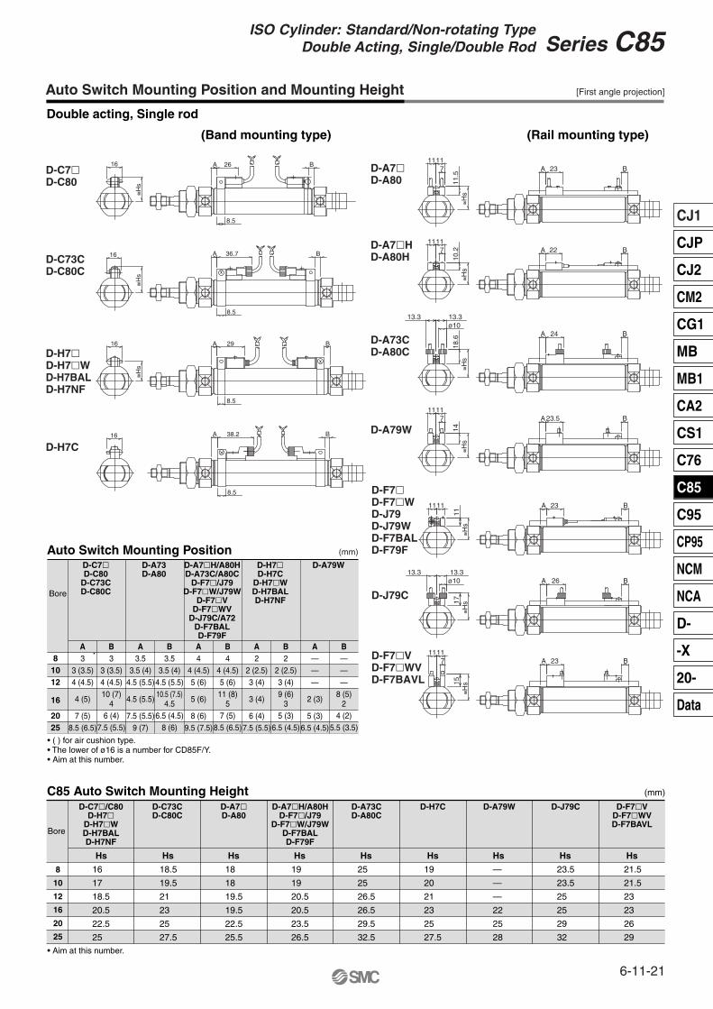
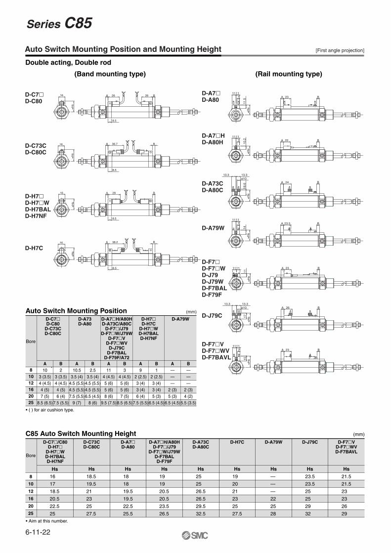
Auto Switch Mounting Position and Mounting Height
Double acting, Single rod
(Band mounting type) (Rail mounting type)
[First angle projection]
(mm)
D-C73CD-C80C
16
≅Hs
A 36.7
8.5
B
D-C7�D-C80
16
≅Hs
A 26
8.5
B
D-H7�D-H7�WD-H7BALD-H7NF
16
≅Hs
A 29 B
8.5
D-H7C16 A
8.5
38.2 B
D-A7�D-A80
23A B1111
≅Hs
11.5
7
D-A7�HD-A80H
22A B1111
≅Hs
10.27
D-A79W23.5A B
1111
≅Hs
14
7
D-A73CD-A80C
A B24
≅Hs
18.6
ø1013.313.3
D-F7�D-F7�WD-J79D-J79WD-F7BALD-F79F
23A B1111
≅Hs
11
D-J79C
17≅H
s
ø1013.313.3
A B26
D-F7�VD-F7�WVD-F7BAVL
23A B1111
7
15≅H
s
Auto Switch Mounting Position
C85 Auto Switch Mounting Height
81012
16
2025
A3
3 (3.5)4 (4.5)
4 (5)
7 (5)8.5 (6.5)
B3
3 (3.5)4 (4.5)10 (7)
46 (4)
7.5 (5.5)
A3.5
3.5 (4)4.5 (5.5)
4.5 (5.5)
7.5 (5.5)9 (7)
B3.5
3.5 (4)4.5 (5.5)10.5 (7.5)
4.56.5 (4.5)
8 (6)
A4
4 (4.5)5 (6)
5 (6)
8 (6)9.5 (7.5)
B4
4 (4.5)5 (6)
11 (8)5
7 (5)8.5 (6.5)
A2
2 (2.5)3 (4)
3 (4)
6 (4)7.5 (5.5)
B2
2 (2.5)3 (4)9 (6)
35 (3)
6.5 (4.5)
A———
2 (3)
5 (3)6.5 (4.5)
B———
8 (5)2
4 (2)5.5 (3.5)
Bore
8
10
12
16
20
25
Bore
• ( ) for air cushion type.• The lower of ø16 is a number for CD85F/Y.• Aim at this number.
• Aim at this number.
D-C7�D-C80
D-C73CD-C80C
D-A73D-A80
D-A7�H/A80HD-A73C/A80C
D-F7�/J79D-F7�W/J79W
D-F7�VD-F7�WV
D-J79C/A72D-F7BALD-F79F
D-C7�/C80D-H7�
D-H7�WD-H7BALD-H7NF
D-A7�H/A80HD-F7�/J79
D-F7�W/J79WD-F7BALD-F79F
D-F7�VD-F7�WVD-F7BAVL
D-C73CD-C80C
D-A73CD-A80C
D-H7C D-A79W D-J79CD-A7�D-A80
D-H7�D-H7C
D-H7�WD-H7BALD-H7NF
D-A79W
(mm)
Hs HsHs Hs Hs Hs Hs Hs Hs
18.5
19.5
21
23
25
27.5
18
18
19.5
19.5
22.5
25.5
16
17
18.5
20.5
22.5
25
19
19
20.5
20.5
23.5
26.5
25
25
26.5
26.5
29.5
32.5
19
20
21
23
25
27.5
—
—
—
22
25
28
23.5
23.5
25
25
29
32
21.5
21.5
23
23
26
29
6-11-21
CJ1
CJP
CJ2
CM2
CG1
MB
MB1
CA2
CS1
C76
C85
C95
CP95
NCM
NCA
D-
-X
20-
Data
Series C85ISO Cylinder: Standard/Non-rotating Type
Double Acting, Single/Double Rod
Auto Switch Mounting Position and Mounting Height
Double acting, Double rod
(Band mounting type) (Rail mounting type)
[First angle projection]
(mm)
Auto Switch Mounting Position
C85 Auto Switch Mounting Height
81012162025
A10
3 (3.5)4 (4.5)4 (5)7 (5)
8.5 (6.5)
B2
3 (3.5)4 (4.5)4 (5)6 (4)
7.5 (5.5)
A10.5
3.5 (4)4.5 (5.5)4.5 (5.5)7.5 (5.5)
9 (7)
B2.5
3.5 (4)4.5 (5.5)4.5 (5.5)6.5 (4.5)
8 (6)
A11
4 (4.5)5 (6)5 (6)8 (6)
9.5 (7.5)
B3
4 (4.5)5 (6)5 (6)7 (5)
8.5 (6.5)
A9
2 (2.5)3 (4)3 (4)6 (4)
7.5 (5.5)
B1
2 (2.5)3 (4)3 (4)5 (3)
6.5 (4.5)
A———
2 (3)5 (3)
6.5 (4.5)
B———
2 (3)4 (2)
5.5 (3.5)
Bore
8
10
12
16
20
25
Bore
• ( ) for air cushion type.
• Aim at this number.
D-C7�D-C80
D-C73CD-C80C
D-A73D-A80
D-A7�H/A80HD-A73C/A80C
D-F7�/J79D-F7�W/J79W
D-F7�VD-F7�WV
D-J79CD-F7BAL
D-F79F/A72
D-C7�/C80D-H7�
D-H7�WD-H7BALD-H7NF
D-A7�H/A80HD-F7�/J79
D-F7�W/J79WD-F7BALD-F79F
D-F7�VD-F7�WVD-F7BAVL
D-C73CD-C80C
D-A73CD-A80C
D-H7C D-A79W D-J79CD-A7�D-A80
D-H7�D-H7C
D-H7�WD-H7BALD-H7NF
D-A79W
(mm)
HsHs Hs Hs Hs Hs Hs Hs
18.5
19.5
21
23
25
27.5
18
18
19.5
19.5
22.5
25.5
16
17
18.5
20.5
22.5
25
19
19
20.5
20.5
23.5
26.5
25
25
26.5
26.5
29.5
32.5
19
20
21
23
25
27.5
—
—
—
22
25
28
23.5
23.5
25
25
29
32
21.5
21.5
23
23
26
29
D-C7�D-C80
16
≅Hs
26
8.5
A 26 B
D-C73CD-C80C
16
≅Hs
A 36.7
8.5
B
D-H7CA
8.5
38.2 B16
≅Hs
D-H7�D-H7�WD-H7BALD-H7NF
A 29
8.5
B16
≅Hs
D-A7�HD-A80H 22A B
≅Hs
1111
10.27
D-A79W23.5A B
≅Hs
1111
14
7
D-A7�D-A80
23A B
≅Hs
1111
11.5
7
D-A73CD-A80C
≅Hs
18.6
ø1013.313.3
B24A
D-F7�D-F7�WD-J79D-J79WD-F7BALD-F79F
23A B1111
≅Hs
11
D-J79C 17≅H
s
ø1013.313.3
A B26
D-F7�VD-F7�WVD-F7BAVL
11117
15≅H
s
A B23
Hs
6-11-22
Series C85
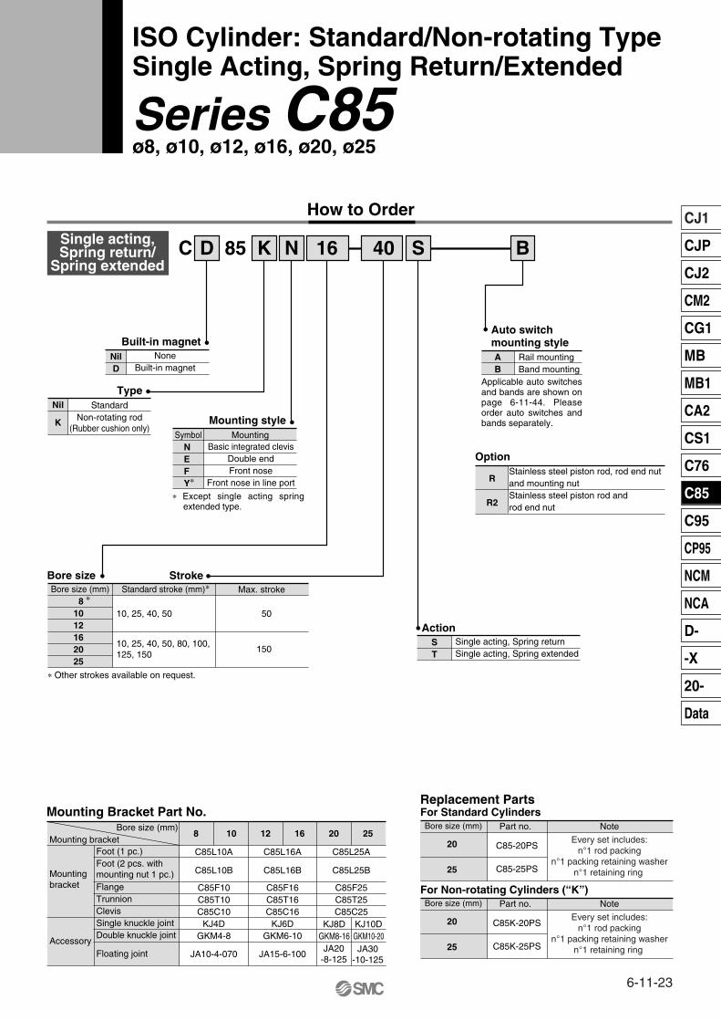
How to Order
Single acting,Spring return/
Spring extendedD 85C K N 16 S40 B
Built-in magnet
Type
Symbol
Mounting style
Basic integrated clevisDouble endFront nose
Front nose in line port
NilD
NoneBuilt-in magnet
Nil Standard
Auto switchmounting styleAB
Rail mountingBand mounting
K Non-rotating rod(Rubber cushion only)
NEFY∗
Standard stroke (mm)∗Bore size (mm) Max. stroke
10, 25, 40, 50
10, 25, 40, 50, 80, 100,125, 150
50
150
∗ Other strokes available on request.
Mounting bracketBore size (mm)
Mounting Bracket Part No.
ActionST
Single acting, Spring returnSingle acting, Spring extended
Option
Foot (1 pc.)
Floating jointAccessory
Foot (2 pcs. withmounting nut 1 pc.)Mounting
bracket FlangeTrunnionClevisSingle knuckle jointDouble knuckle joint
8 10 12 16 20 25
C85L10A
C85L10B
JA10-4-070
C85F10C85T10C85C10
KJ4DGKM4-8
C85L16A C85L25A
C85L16B C85L25B
C85F25C85T25C85C25
JA15-6-100
C85F16C85T16C85C16
KJ6DGKM6-10
KJ8DGKM8-16
KJ10DGKM10-20JA30
-10-125JA20
-8-125
Bore size (mm)
Replacement PartsFor Standard Cylinders
20
25
Part no. Note
C85-20PS
C85-25PS
Every set includes:n°1 rod packing
n°1 packing retaining washern°1 retaining ring
Bore size (mm)
For Non-rotating Cylinders (“K”)
20
25
Part no. Note
C85K-20PS
C85K-25PS
Every set includes:n°1 rod packing
n°1 packing retaining washern°1 retaining ring
Mounting
R
R2
Stainless steel piston rod, rod end nut and mounting nutStainless steel piston rod and rod end nut
ISO Cylinder: Standard/Non-rotating Type Single Acting, Spring Return/Extended
Series C85ø8, ø10, ø12, ø16, ø20, ø25
∗ Except single acting spring extended type.
81012162025
∗
Applicable auto switches and bands are shown on page 6-11-44. Please order auto switches and bands separately.
StrokeBore size
6-11-23
CJ1
CJP
CJ2
CM2
CG1
MB
MB1
CA2
CS1
C76
C85
C95
CP95
NCM
NCA
D-
-X
20-
Data
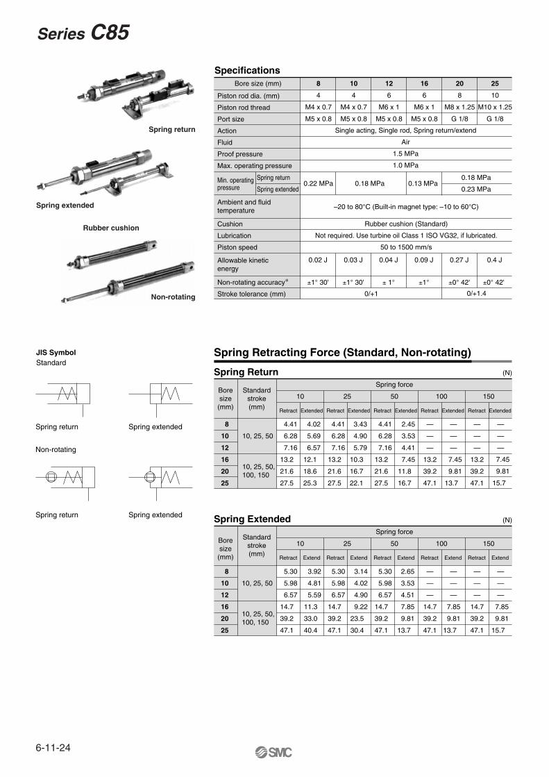
Specifications
Piston rod dia. (mm)
Piston rod thread
Port size
Action
Fluid
Proof pressure
Max. operating pressure
8
4
M4 x 0.7
M5 x 0.8
10
4
M4 x 0.7
M5 x 0.8
12
6
M6 x 1
M5 x 0.8
16
6
M6 x 1
M5 x 0.8
20
8
M8 x 1.25
G 1/8
25
10
M10 x 1.25
G 1/8
Single acting, Single rod, Spring return/extend
Air
1.5 MPa
1.0 MPa
0.22 MPa 0.18 MPa 0.13 MPa
–20 to 80°C (Built-in magnet type: –10 to 60°C)
0.02 J 0.03 J 0.04 J 0.09 J 0.27 J 0.4 J
±1° 30' ±1° 30' ± 1°
0/+1
±1° ±0° 42' ±0° 42'
0/+1.4
Rubber cushion (Standard)
Not required. Use turbine oil Class 1 ISO VG32, if lubricated.
50 to 1500 mm/s
Min. operating pressure
Cushion
Lubrication
Piston speed
Ambient and fluid temperature
Non-rotating accuracy∗
Stroke tolerance (mm)
Allowable kineticenergy
Spring Return
Spring Retracting Force (Standard, Non-rotating)
(N)
Spring return Spring extended
Spring return Spring extended
Non-rotating
Boresize(mm)
Standardstroke(mm)
8
10
12
16
20
25
10, 25, 50
10, 25, 50,100, 150
Spring force
10 25 50 100 150
4.41
6.28
7.16
13.2
21.6
27.5
4.02
5.69
6.57
12.1
18.6
25.3
4.41
6.28
7.16
13.2
21.6
27.5
3.43
4.90
5.79
10.3
16.7
22.1
4.41
6.28
7.16
13.2
21.6
27.5
2.45
3.53
4.41
7.45
11.8
16.7
—
—
—
13.2
39.2
47.1
—
—
—
—
—
—
13.2
39.2
47.1
—
—
—
Spring Extended (N)
Boresize(mm)
Standardstroke(mm)
8
10
12
16
20
25
10, 25, 50
10, 25, 50,100, 150
Spring force
10 25 50 100 150
Retract Extend Retract Extend Retract Extend Retract Extend Retract Extend
Retract Extended Retract Extended Retract Extended Retract Extended Retract Extended
5.30
5.98
6.57
14.7
39.2
47.1
3.92
4.81
5.59
11.3
33.0
40.4
5.30
5.98
6.57
14.7
39.2
47.1
3.14
4.02
4.90
9.22
23.5
30.4
5.30
5.98
6.57
14.7
39.2
47.1
2.65
3.53
4.51
7.85
9.81
13.7
—
—
—
14.7
39.2
47.1
—
—
—
—
—
—
14.7
39.2
47.1
—
—
—
Spring return
Spring extended
Non-rotating
Rubber cushion
Bore size (mm)
7.45
9.81
15.7
7.45
9.81
13.7
7.85
9.81
13.7
7.85
9.81
15.7
JIS SymbolStandard
Spring return
Spring extended
0.18 MPa
0.23 MPa
6-11-24
Series C85
6-11-25
CJ1
CJP
CJ2
CM2
CG1
MB
MB1
CA2
CS1
C76
C85
C95
CP95
NCM
NCA
D-
-X
20-
Data
Series C85ISO Cylinder: Standard/Non-rotating Type
Single Acting, Spring Return/Extended
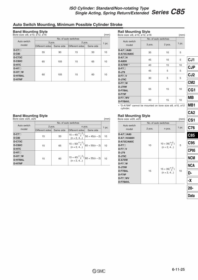
Band Mounting Style
Auto Switch Mounting, Minimum Possible Cylinder Stroke
No. of auto switches
3 pcs. 2 pcs.
Different sides
55
65
60
Same side
90
105
105
Same side
50
65
60
15
15
15
1 pc.
10
10
10
Different sides
Auto switch
model
D-C7�D-C80D-C73CD-C80CD-H7C D-H7�D-H7�WD-H7BALD-H7NF
(mm)Bore size: ø8, ø10, ø12, ø16
35
45
40
45
30
55
40
10
10
15
5
5
15
15
5
5
10
5
5
10
10
Rail Mounting Style
No. of auto switches
3 pcs. 2 pcs.Auto switch
model
D-A7�/A80D-A73C/A80CD-A7�HD-A80HD-A79W ∗
D-F7�D-J79D-F7�VD-J79CD-F7�WD-J79WD-F7BALD-F79FD-F7�WVD-F7BAVL
1 pc.
(mm)Bore size: ø8, ø10, ø12, ø16
Band Mounting Style
No. of auto switches
2 pcs. n pcs.
Different sides
15
15
15
Same side
50
65
60
Same side1 pc.
10
10
10
Different sides
Auto switch
model
D-C7�D-C80D-C73CD-C80CD-H7C D-H7�D-H7�WD-H7BALD-H7NF
(mm)Bore size: ø20, ø25Rail Mounting Style
No. of auto switches
2 pcs. n pcs.Auto switch
model
D-A7�/A80D-A7�H/A80HD-A73C/A80CD-F7�D-F7�VD-J79D-J79CD-A79WD-F7�WD-J79WD-F7BALD-F79FD-F7�WVD-F7BAVL
1 pc.
(mm)Bore size: ø20, ø25
50 + 45(n – 2)
65 + 50(n – 2)
60 + 55(n – 2)
15 + 45(n = 2, 4...)
( n – 2 )2
15 + 50(n = 2, 4...)
( n – 2 )2
15 + 45(n = 2, 4...)
( n – 2 )2
)10 + 35(n = 2, 4...)
( n–22
)15 + 35(n = 2, 4...)
( n–22
10
15
5
10
∗ “D-A79W” cannot be mounted on bore size ø8, ø10, ø12 cylinder.
6-11-25
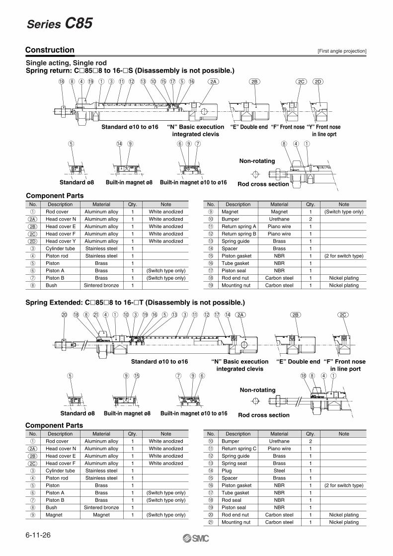
Construction
Single acting, Single rodSpring return: C�85�8 to 16-�S (Disassembly is not possible.)
No.
Rod cover
Head cover N
Head cover E
Head cover F
Head cover Y
Cylinder tube
Piston rod
Piston
Piston A
Piston B
Bush
Material
Aluminum alloy
Aluminum alloy
Aluminum alloy
Aluminum alloy
Aluminum alloy
Stainless steel
Stainless steel
Brass
Brass
Brass
Sintered bronze
1
1
1
1
1
1
1
1
1
1
1
Note
White anodized
White anodized
White anodized
White anodized
White anodized
(Switch type only)
(Switch type only)
Component Parts
2A
2B
2C
2D
Description Qty.
q
e
r
t
y
u
i
No.
Magnet
Bumper
Return spring A
Return spring B
Spring guide
Spacer
Piston gasket
Tube gasket
Piston seal
Rod end nut
Mounting nut
Material
Magnet
Urethane
Piano wire
Piano wire
Brass
Brass
NBR
NBR
NBR
Carbon steel
Carbon steel
1
2
1
1
1
1
1
1
1
1
1
Note
(Switch type only)
(2 for switch type)
Nickel plating
Nickel plating
Description Qty.
o
!0
!1
!2
!3
!4
!5
!6
!7
!8
!9
No.
Rod cover
Head cover N
Head cover E
Head cover F
Cylinder tube
Piston rod
Piston
Piston A
Piston B
Bush
Magnet
Material
Aluminum alloy
Aluminum alloy
Aluminum alloy
Aluminum alloy
Stainless steel
Stainless steel
Brass
Brass
Brass
Sintered bronze
Magnet
1
1
1
1
1
1
1
1
1
1
1
Note
White anodized
White anodized
White anodized
White anodized
(Switch type only)
(Switch type only)
(Switch type only)
Component Parts
2A
2B
2C
Description Qty.
q
e
r
t
y
u
i
o
No.
Bumper
Return spring C
Spring guide
Spring seat
Plug
Spacer
Piston gasket
Tube gasket
Rod seal
Piston seal
Rod end nut
Mounting nut
Material
Urethane
Piano wire
Brass
Brass
Steel
Brass
NBR
NBR
NBR
NBR
Carbon steel
Carbon steel
2
1
1
1
1
1
1
1
1
1
1
1
Note
(2 for switch type)
Nickel plating
Nickel plating
Description Qty.
!0
!1
!2
!3
!4
!5
!6
!7
!8
!9
@0
@1
Spring Extended: C�85�8 to 16-�T (Disassembly is not possible.)
!8 i r !9 q e !1 !2 !3 !0 !5 !7 t !6 2A 2B 2C 2D
t !4 o y o u i r q
@0 !8 i @1 r q !0 e !9 !6 t !3 e !1 !2 !7 !4 2A 2B 2C
t o !5 u o y !8 i r q
Standard ø10 to ø16 “N” Basic executionintegrated clevis
“E” Double end “F” Front nose “Y” Front nose in line oprt
Standard ø10 to ø16 “N” Basic executionintegrated clevis
“E” Double end “F” Front nose in line port
Non-rotating
Rod cross sectionBuilt-in magnet ø10 to ø16Built-in magnet ø8Standard ø8
Non-rotating
Rod cross sectionBuilt-in magnet ø10 to ø16Built-in magnet ø8Standard ø8
[First angle projection]
6-11-26
Series C85
Construction
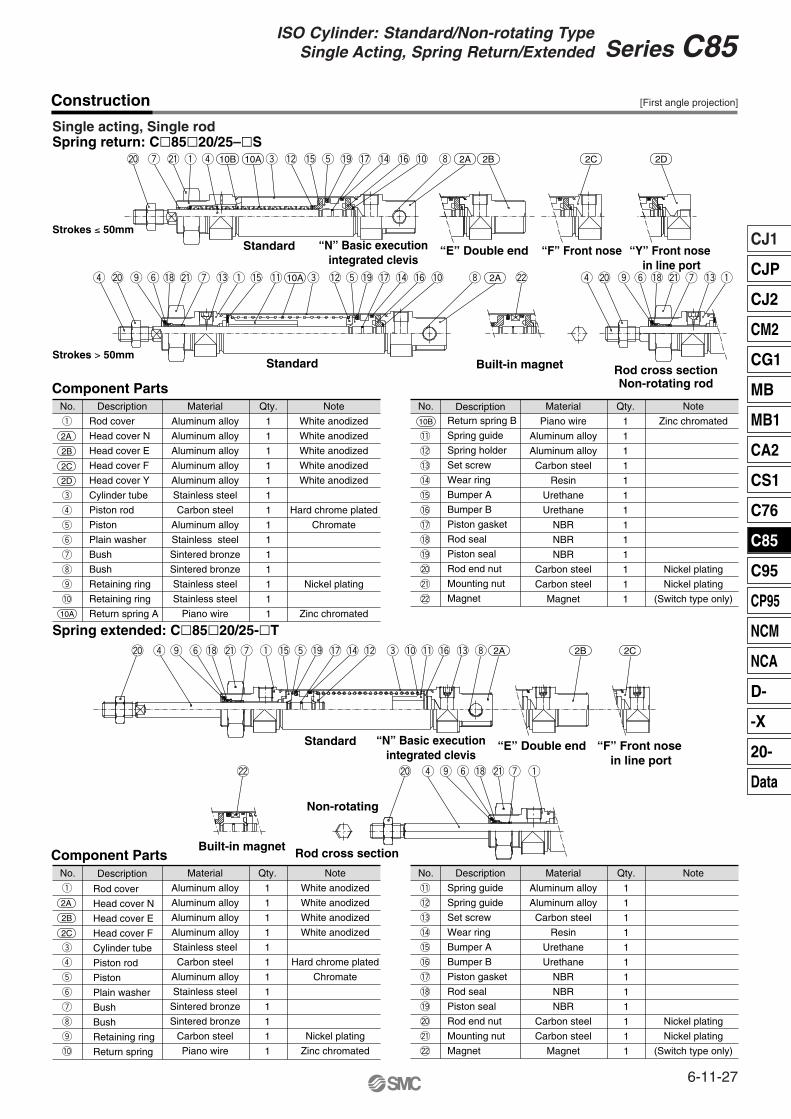
Single acting, Single rodSpring return: C�85�20/25–�S
No.
Rod cover
Head cover N
Head cover E
Head cover F
Head cover Y
Cylinder tube
Piston rod
Piston
Plain washer
Bush
Bush
Retaining ring
Retaining ring
Return spring A
Material
Aluminum alloy
Aluminum alloy
Aluminum alloy
Aluminum alloy
Aluminum alloy
Stainless steel
Carbon steel
Aluminum alloy
Stainless steel
Sintered bronze
Sintered bronze
Stainless steel
Stainless steel
Piano wire
1
1
1
1
1
1
1
1
1
1
1
1
1
1
Note
White anodized
White anodized
White anodized
White anodized
White anodized
Hard chrome plated
Chromate
Nickel plating
Zinc chromated
Component Parts
2A
2B
2C
2D
10A
Description Qty.
q
e
r
t
y
u
i
o
!0
No.Return spring B
Spring guide
Spring holder
Set screw
Wear ring
Bumper A
Bumper B
Piston gasket
Rod seal
Piston seal
Rod end nut
Mounting nut
Magnet
Material
Piano wire
Aluminum alloy
Aluminum alloy
Carbon steel
Resin
Urethane
Urethane
NBR
NBR
NBR
Carbon steel
Carbon steel
Magnet
1
1
1
1
1
1
1
1
1
1
1
1
1
Note
Zinc chromated
Nickel plating
Nickel plating
(Switch type only)
Description Qty.
!1
!2
!3
!4
!5
!6
!7
!8
!9
@0
@1
@2
No.
Rod cover
Head cover N
Head cover E
Head cover F
Cylinder tube
Piston rod
Piston
Plain washer
Bush
Bush
Retaining ring
Return spring
Material
Aluminum alloy
Aluminum alloy
Aluminum alloy
Aluminum alloy
Stainless steel
Carbon steel
Aluminum alloy
Stainless steel
Sintered bronze
Sintered bronze
Carbon steel
Piano wire
1
1
1
1
1
1
1
1
1
1
1
1
Note
White anodized
White anodized
White anodized
White anodized
Hard chrome plated
Chromate
Nickel plating
Zinc chromated
Component Parts
2A
2B
2C
Description Qty.
q
e
r
t
y
u
i
o
!0
No.
Spring guide
Spring guide
Set screw
Wear ring
Bumper A
Bumper B
Piston gasket
Rod seal
Piston seal
Rod end nut
Mounting nut
Magnet
Material
Aluminum alloy
Aluminum alloy
Carbon steel
Resin
Urethane
Urethane
NBR
NBR
NBR
Carbon steel
Carbon steel
Magnet
1
1
1
1
1
1
1
1
1
1
1
1
Note
Nickel plating
Nickel plating
(Switch type only)
Description Qty.
!1
!2
!3
!4
!5
!6
!7
!8
!9
@0
@1
@2
Spring extended: C�85�20/25-�T
10B 10A
10B
@0 u @1 q r e !2 !5 t !9 !7 !4 !6 !0 i 2A 2B 2C 2D
r @0 o y !8 @1 u !3 q !5 !1 10A e !2 t !9 !7 !4 !6 !0 i 2A @2 r @0 o y !8 @1 u !3 q
@0 r o y !8 @1 u q !5 t !9 !7 !4 !2 e !0 !1 !6 !3 i 2A 2B 2C
@2 @0 r o y !8 @1 u q
Strokes ≤ 50mm
Strokes > 50mm
Standard
Standard
“N” Basic executionintegrated clevis
“E” Double end “F” Front nose
Standard “N” Basic executionintegrated clevis
“E” Double end “F” Front nose in line port
“Y” Front nose in line port
Built-in magnet Rod cross sectionNon-rotating rod
Built-in magnet
Non-rotating
Rod cross section
[First angle projection]
6-11-27
CJ1
CJP
CJ2
CM2
CG1
MB
MB1
CA2
CS1
C76
C85
C95
CP95
NCM
NCA
D-
-X
20-
Data
Series C85ISO Cylinder: Standard/Non-rotating Type
Single Acting, Spring Return/Extended
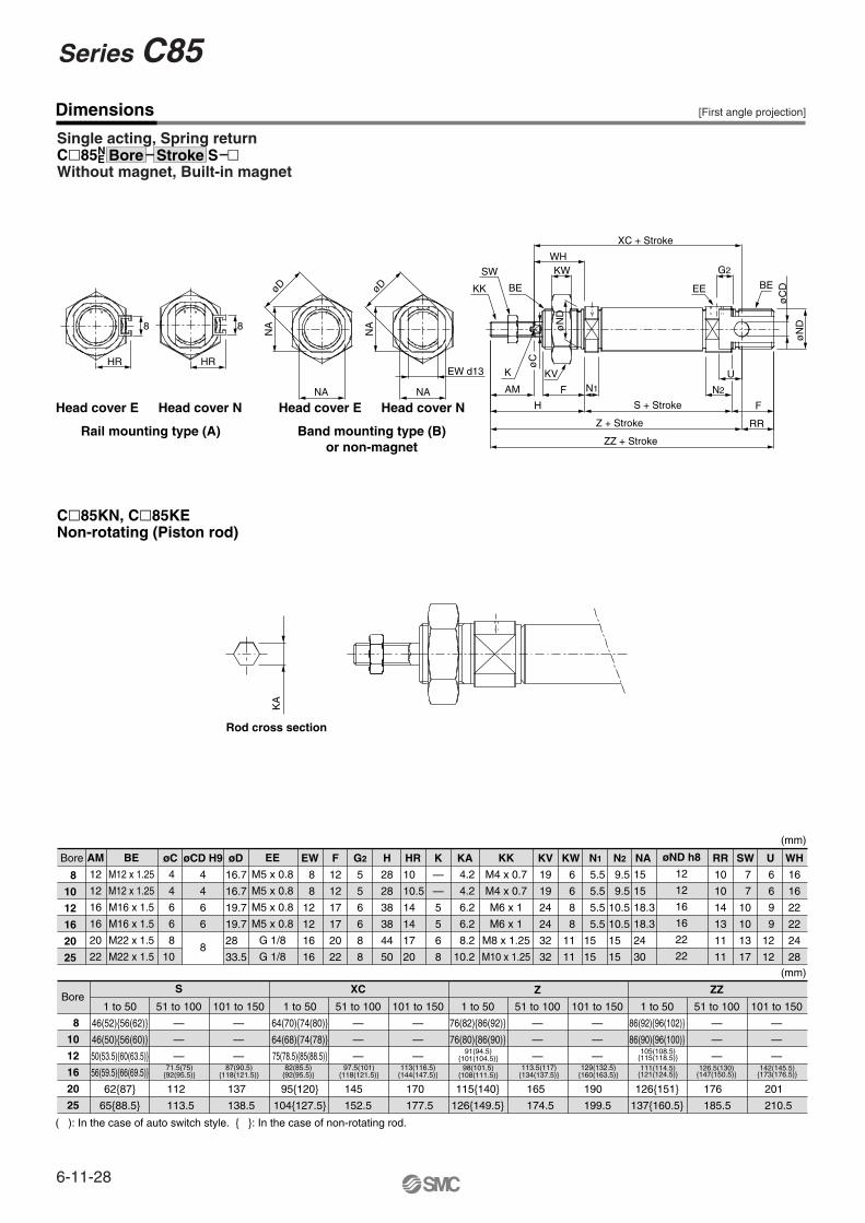
Dimensions
Single acting, Spring returnC�85N
EWithout magnet, Built-in magnet
Bore øC øCD H9
4
4
6
6
AM
12
12
16
16
20
22
Bore
8
10
12
16
20
25
1 to 50
46(52){56(62)}
46(50){56(60)}
50(53.5){60(63.5)}
56(59.5){66(69.5)}
62{87}
65{88.5}
51 to 100
—
—
—
S
101 to 150
—
—
—
1 to 50
64(70){74(80)}
64(68){74(78)}
75(78.5){85(88.5)}
95{120}
104{127.5}
51 to 100
—
—
—
XC
101 to 150
—
—
—
1 to 50
76(82){86(92)}
76(80){86(90)}
115{140}
126{149.5}
51 to 100
—
—
—
Z
101 to 150
—
—
—
1 to 50
86(92){96(102)}
86(90){96(100)}
126{151}
137{160.5}
51 to 100
—
—
—
ZZ
101 to 150
—
—
—
øD EW F
12
12
17
17
20
22
G2
5
5
6
6
8
8
H
28
28
38
38
44
50
HR K
—
—
5
5
6
8
KA KV
19
19
24
24
32
32
KW NAN1 N2 øND h8
12
12
16
16
22
22
KK
M4 x 0.7
M4 x 0.7
M6 x 1
M6 x 1
M8 x 1.25
M10 x 1.25
EE
M5 x 0.8
M5 x 0.8
M5 x 0.8
M5 x 0.8
G 1/8
G 1/8
BE
M12 x 1.25
M12 x 1.25
M16 x 1.5
M16 x 1.5
M22 x 1.5
M22 x 1.5
U WH
16
16
22
22
24
28
SWRR
10
10
14
13
11
11
C�85KN, C�85KENon-rotating (Piston rod)
71.5(75){92(95.5)}
87(90.5){118(121.5)}
82(85.5){92(95.5)}
97.5(101){118(121.5)}
113(116.5){144(147.5)}
113.5(117){134(137.5)}
129(132.5){160(163.5)}
105(108.5){115(118.5)}111(114.5)
{121(124.5)}126.5(130)
{147(150.5)}142(145.5)
{173(176.5)}
91(94.5){101(104.5)}
98(101.5){108(111.5)}
( ): In the case of auto switch style. { }: In the case of non-rotating rod.
øD øD
NA
NA
NA NA
EW d13 K
AM F
KV
øC
H
N1
ZZ + Stroke
Z + Stroke
S + Stroke
N2
U
F
RR
øN
D
øC
DBE
G2
EE
XC + Stroke
WHKW
øN
D
SW
BEKKK
A
Head cover E Head cover NHead cover E Head cover N
HR HR
8 8
Rail mounting type (A) Band mounting type (B)or non-magnet
Rod cross section
8
8
10
12
16
20
25
4
4
6
6
8
10
8
8
12
12
16
16
10
10.5
14
14
17
20
4.2
4.2
6.2
6.2
8.2
10.2
6
6
8
8
11
11
5.5
5.5
5.5
5.5
15
15
9.5
9.5
10.5
10.5
15
15
6
6
9
9
12
12
7
7
10
10
13
17
201
210.5
176
185.5
190
199.5
165
174.5
112
113.5
137
138.5
145
152.5
170
177.5
Bore Stroke S
[First angle projection]
(mm)
(mm)
16.7
16.7
19.7
19.7
28
33.5
15
15
18.3
18.3
24
30
6-11-28
Series C85
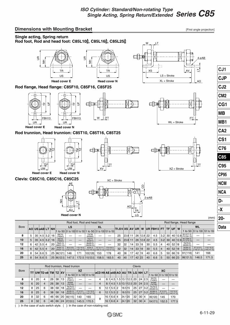
Dimensions with Mounting Bracket
Single acting, Spring returnRod foot, Rod and head foot: C85L10A
B, C85L16AB, C85L25A
B
Rod flange, Head flange: C85F10, C85F16, C85F25
Rod trunnion, Head trunnion: C85T10, C85T16, C85T25
Clevis: C85C10, C85C16, C85C25
Bore
Bore
AO
5
5
6
6
8
8
6
6
8
8
8
8
35
35
42
42
54
54
4.5
4.5
5.5
5.5
6.6
6.6
3.2
3.2
4
4
5
5
16
16
20
20
25
25
US øAB LT NHLS
1 to 50
96{121}
96{122.5}
51 to 100
—
—
—
101 to 150
—
—
—
XLXS
25
25
32
32
40
40
23.8
23.8
32
32
36
40
AV
11
11
14
14
17
17
UR
26
26
33
33
42
42
W
12.8
12.8
18
18
19
23
UR
22
22
30
30
40
40
FT
3.2
3.2
4
4
5
5
TF
Rod flange, Head flange
30
30
40
40
50
50
UF
40
40
52
52
66
66
WWL
1 to 50
91{116}
98{121.5}
51 to 100
—
—
—
101 to 150
—
—
—
12.8
12.8
18
18
19
23
FBH13
4.5
4.5
5.5
5.5
6.6
6.6
TR JS14
Rod foot, Rod and head foot
1 to 50
103{128}
110{133.5}
51 to 100
—
—
—
101 to 150
—
—
—
8
10
12
16
20
25
TT
20
20
25
25
32
32
UW
26
26
38
38
46
46
TM
Rod trunnion, Head trunion Clevis
38
38
58
58
66
66
TZ
13
13
18
18
20
24
XV
8.1
8.1
12.1
12.1
16.1
16.1
AE
4.5
4.5
5.5
5.5
6.6
6.6
øAB
1.5
1.5
2
2
4
4
AO
13.1
13.1
18.5
18.5
24.1
24.1
AU
12.5
12.5
15
15
20
20
TR
20
20
25
25
32
32
LG
24
24
27
27
30
30
NH
2.5
2.5
3.2
3.2
4
4
LT
4
4
6
6
øCD H9
4
4
6
6
6
6
TD e8
8
10
12
16
20
25
68(74){78(84)}68(72)
{78(82)}78(81.5)
{88(91.5)}84(87.5)
{94(97.5)}
73(79){83(89)}73(77)
{83(87)}86(89.5)
{96(99.5)}92(95.5)
{102(105.5)}99.5(103)
{120(123.5)}115(118.5)
{146(149.5)}107.5(111)
{128(131.5)}123(126.5)
{154(157.5)}
65.2(71.2){75.2(81.2)}65.2(69.2)
{75.2(79.2)}76(79.5)
{86(89.5)}82(85.5)
{92(95.5)}97.5(101)
{118(121.5)}113(116.5)
{144(147.5)}
XZ1 to 50
90{115}
97{120.5}
51 to 100
—
—
—
101 to 150
—
—
—
65(71){75(81)}65(69)
{75(79)}76(79.5)
{86(89.5)}82(85.5)
{92(95.5)}97.5(101)
{118(121.5)}113(116.5)
{144(147.5)}
XC1 to 50
95{120}
104{127.5}
51 to 100
—
—
—
101 to 150
—
—
—
64(70){74(80)}64(68)
{74(78)}75(78.5)
{85(88.5)}82(88.5)
{92(95.5)}97.5(101)
{118(121.5)}113(116.5)
{144(147.5)}
( ): In the case of auto switch style. { }: In the case of non-rotating rod.
8
UR
UR
NH
NH
TR
US
TR
US
W LT
XS
LS + Stroke
XL + Stroke
AV
AO
LT
4-øAB
UR
FBH13
UR
FBH13
TF
UF
TF
UF
W FT
WL + Stroke
FT
UW UW
TDe8 TDe8
TM TZ
TM TZ
XV
TT
XZ + Stroke
TT
NH
AE
LT
AU
XC + Stroke
CD
2-øAB
LG
TR
AO
Head cover E
Head cover E
Head cover E
Head cover N
Head cover N
Head cover N
Head cover N
146
147.5
171
172.5
153
158.5
178
183.5
141
146.5
166
171.5
140
145.5
165
170.5
145
152.5
170
177.5
[First angle projection]
(mm)
6-11-29
CJ1
CJP
CJ2
CM2
CG1
MB
MB1
CA2
CS1
C76
C85
C95
CP95
NCM
NCA
D-
-X
20-
Data
Series C85ISO Cylinder: Standard/Non-rotating Type
Single Acting, Spring Return/Extended
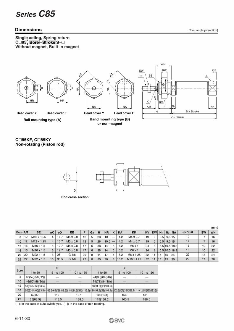
Dimensions
Single acting, Spring returnC�85F
YWithout magnet, Built-in magnet
C�85KF, C�85KYNon-rotating (Piston rod)
Bore øCAM
12
12
16
16
20
22
BoreS
1 to 50
46(52){56(62)}
46(50){56(60)}
50(53.5){60(63.5)}
50(53.5){60(63.5)}
62{87}
65{88.5}
51 to 100
—
—
—
65.5(69){86(89.5)}
101 to 150
—
—
—
81(84.5){112(115.5)}
1 to 50
74(80){84(90)}
74(78){84(88)}
88(91.5){98(101.5)}
88(91.5){98(101.5)}
106{131}
115{138.5}
51 to 100
—
—
—
103.5(107){124(127.5)}
Z
101 to 150
—
—
—
119(122.5){150(153.5)}
16.7
16.7
19.7
19.7
28
33.5
F
12
12
17
17
20
22
G2
5
5
6
6
8
8
H
28
28
38
38
44
50
HR K
—
—
5
5
6
8
KA KV
19
19
24
24
32
32
KW NAN1 N2 øND h8
12
12
16
16
22
22
KK
M4 x 0.7
M4 x 0.7
M6 x 1
M6 x 1
M8 x 1.25
M10 x 1.25
EE
M5 x 0.8
M5 x 0.8
M5 x 0.8
M5 x 0.8
G 1/8
G 1/8
BE
M12 x 1.25
M12 x 1.25
M16 x 1.5
M16 x 1.5
M22 x 1.5
M22 x 1.5
WH
16
16
22
22
24
28
SW
( ): In the case of auto switch type. { }: In the case of non-rotating.
KA
øD øDN
A
NA
NA NA
K
AM F
KV
H
øC
N1
Z + Stroke
S + Stroke
N2
G2
EE
WH
KW
BE
øND
SW
KK
HR
8
HR
8
Head cover Y Head cover F Head cover Y Head cover F
Rail mounting type (A) Band mounting type (B)or non-magnet
Rod cross section
8
10
12
16
20
25
8
10
12
16
20
25
4
4
6
6
8
10
10
10.5
14
14
17
20
4.2
4.2
6.2
6.2
8.2
10.2
6
6
8
8
11
11
5.5
5.5
5.5
5.5
15
15
9.5
9.5
10.5
10.5
15
15
7
7
10
10
13
17
181
188.5
156
163.5
137
138.5
112
113.5
Bore Stroke S
[First angle projection]
(mm)
øD
15
15
18.3
18.3
24
30
6-11-30
Series C85
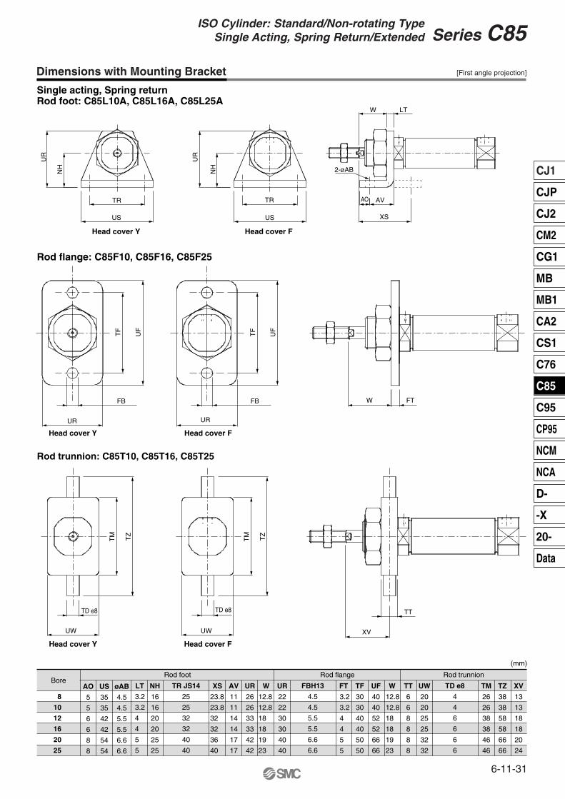
Dimensions with Mounting Bracket
Single acting, Spring returnRod foot: C85L10A, C85L16A, C85L25A
8
10
12
16
20
25
LTAO
5
5
6
6
8
8
US
35
35
42
42
54
54
øAB
4.5
4.5
5.5
5.5
6.6
6.6
NH
16
16
20
20
25
25
XS AV
11
11
14
14
17
17
UR
26
26
33
33
42
42
W UR
22
22
30
30
40
40
FT TF
30
30
40
40
50
50
UF
40
40
52
52
66
66
W TT
6
6
8
8
8
8
UW
20
20
25
25
32
32
FBH13
4.5
4.5
5.5
5.5
6.6
6.6
TD e8
4
4
6
6
6
6
TR JS14
25
25
32
32
40
40
TM
26
26
38
38
46
46
TZ
38
38
58
58
66
66
XV
13
13
18
18
20
24
Rod flange: C85F10, C85F16, C85F25
Rod trunnion: C85T10, C85T16, C85T25
BoreRod foot Rod flange Rod trunnion
UR
NH
UR
NH
TR
US
TR
US
UW
TD e8
UW
TD e8
TM TZ
TM TZ
XV
TT
Head cover Y Head cover F
Head cover Y Head cover F
2-øAB
AO AV
XS
W LT
UR
FB
TF
UF
Head cover Y
TF
UF
UR
FB
Head cover F
W FT
12.8
12.8
18
18
19
23
3.2
3.2
4
4
5
5
12.8
12.8
18
18
19
23
23.8
23.8
32
32
36
40
3.2
3.2
4
4
5
5
[First angle projection]
(mm)
6-11-31
CJ1
CJP
CJ2
CM2
CG1
MB
MB1
CA2
CS1
C76
C85
C95
CP95
NCM
NCA
D-
-X
20-
Data
Series C85ISO Cylinder: Standard/Non-rotating Type
Single Acting, Spring Return/Extended
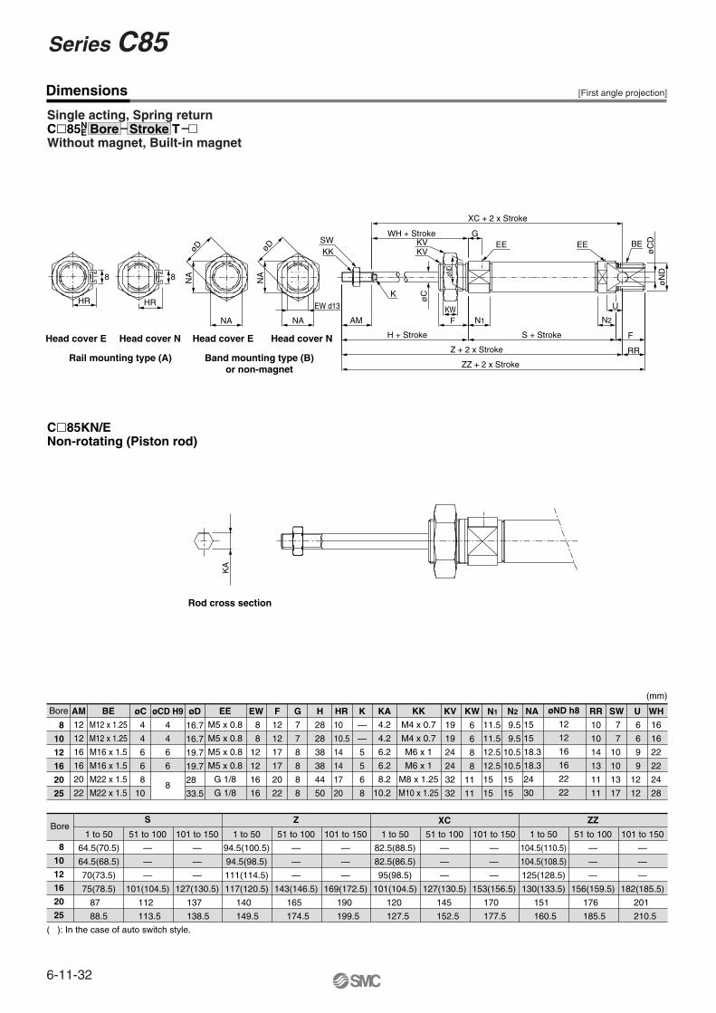
Dimensions
Single acting, Spring returnC�85N
EWithout magnet, Built-in magnet
C�85KN/ENon-rotating (Piston rod)
Bore øC øCD H9
4
4
6
6
AM
12
12
16
16
20
22
Bore1 to 50
64.5(70.5)
64.5(68.5)
70(73.5)
75(78.5)
51 to 100
—
—
—
101(104.5)
S
101 to 150
—
—
—
127(130.5)
1 to 50
94.5(100.5)
94.5(98.5)
111(114.5)
117(120.5)
51 to 100
—
—
—
143(146.5)
Z
101 to 150
—
—
—
169(172.5)
1 to 50
82.5(88.5)
82.5(86.5)
95(98.5)
101(104.5)
51 to 100
—
—
—
127(130.5)
XC
101 to 150
—
—
—
153(156.5)
1 to 50
104.5(110.5)
104.5(108.5)
125(128.5)
130(133.5)
51 to 100
—
—
—
156(159.5)
ZZ
101 to 150
—
—
—
182(185.5)
øD EW F
12
12
17
17
20
22
G
7
7
8
8
8
8
H
28
28
38
38
44
50
HR K
—
—
5
5
6
8
KA KV
19
19
24
24
32
32
KW NAN1 N2 øND h8
12
12
16
16
22
22
KK
M4 x 0.7
M4 x 0.7
M6 x 1
M6 x 1
M8 x 1.25
M10 x 1.25
EE
M5 x 0.8
M5 x 0.8
M5 x 0.8
M5 x 0.8
G 1/8
G 1/8
BE
M12 x 1.25
M12 x 1.25
M16 x 1.5
M16 x 1.5
M22 x 1.5
M22 x 1.5
U WH
16
16
22
22
24
28
SWRR
10
10
14
13
11
11
( ): In the case of auto switch style.
8
Head cover E Head cover NHead cover E Head cover N
Rail mounting type (A) Band mounting type (B)or non-magnet
Rod cross section
HR HR
8 8
øD øD
NA
NA
NA NA
EW d13
AM
H + Stroke
ZZ + 2 x Stroke
Z + 2 x Stroke
K
øC
KWF N1
S + Stroke
RR
F
N2
U
øN
Dø
CDBEEE
XC + 2 x Stroke
EEGWH + Stroke
KVKV
øND
SWKK
KA
8
10
12
16
20
25
8
10
12
16
20
25
4
4
6
6
8
10
8
8
12
12
16
16
10
10.5
14
14
17
20
4.2
4.2
6.2
6.2
8.2
10.2
6
6
8
8
11
11
7
7
10
10
13
17
6
6
9
9
12
12
9.5
9.5
10.5
10.5
15
15
11.5
11.5
12.5
12.5
15
15
176
185.5
201
210.5
151
160.5
170
177.5
145
152.5
120
127.5
190
199.5
87
88.5
112
113.5
137
138.5
140
149.5
165
174.5
Bore Stroke T
[First angle projection]
(mm)
16.7
16.7
19.7
19.7
28
33.5
15
15
18.3
18.3
24
30
6-11-32
Series C85
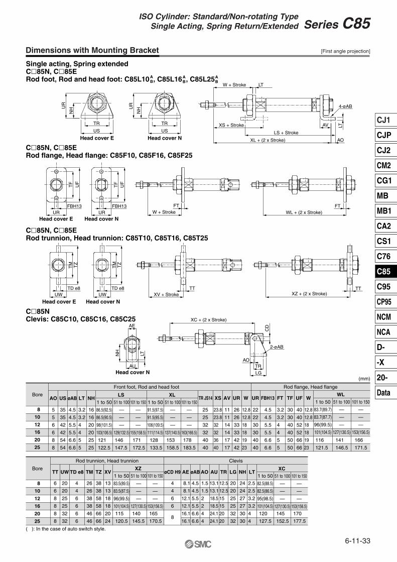
Dimensions with Mounting Bracket
Single acting, Spring extendedC�85N, C�85ERod foot, Rod and head foot: C85L10 , C85L16 , C85L25A
BAB
AB
C�85N, C�85ERod flange, Head flange: C85F10, C85F16, C85F25
C�85N, C�85ERod trunnion, Head trunnion: C85T10, C85T16, C85T25
C�85NClevis: C85C10, C85C16, C85C25
BoreAO
5
5
6
6
8
8
6
6
8
8
8
8
35
35
42
42
54
54
4.5
4.5
5.5
5.5
6.6
6.6
16
16
20
20
25
25
US øAB LT NHLS
1 to 50
86.5(92.5)
86.5(90.5)
98(101.5)
103(106.5)
51 to 100
—
—
—
129(132.5)
101 to 150
—
—
—
155(158.5)
XLXS
25
25
32
32
40
40
23.8
23.8
32
32
36
40
AV
11
11
14
14
17
17
UR
26
26
33
33
42
42
W
12.8
12.8
18
18
19
23
UR
22
22
30
30
40
40
FT
3.2
3.2
4
4
5
5
TF
Rod flange, Head flange
30
30
40
40
50
50
UF
40
40
52
52
66
66
WWL
1 to 50
83.7(89.7)
83.7(87.7)
96(99.5)
101(104.5)
51 to 100
—
—
—
127(130.5)
101 to 150
—
—
—
153(156.5)
12.8
12.8
18
18
19
23
FBH13
4.5
4.5
5.5
5.5
6.6
6.6
TR JS14
Front foot, Rod and head foot
1 to 50
91.5(97.5)
91.5(95.5)
106(109.5)
111(114.5)
51 to 100
—
—
—
137(140.5)
101 to 150
—
—
—
163(166.5)
8
10
12
16
20
25
Bore
8
10
12
16
20
25
TT
20
20
25
25
32
32
UW
26
26
38
38
46
46
TM
Rod trunnion, Head trunnion Clevis
38
38
58
58
66
66
TZ
13
13
18
18
20
24
XV
8.1
8.1
12.1
12.1
16.1
16.1
AE
4.5
4.5
5.5
5.5
6.6
6.6
øAB
1.5
1.5
2
2
4
4
AO
13.1
13.1
18.5
18.5
24.1
24.1
AU
12.5
12.5
15
15
20
20
TR
20
20
25
25
32
32
LG
24
24
27
27
30
30
NH
2.5
2.5
3.2
3.2
4
4
LTøCD H9
4
4
6
6
6
6
TD e8XZ
1 to 50
83.5(89.5)
83.5(87.5)
96(99.5)
101(104.5)
51 to 100
—
—
—
127(130.5)
101 to 150
—
—
—
153(156.5)
XC1 to 50
82.5(88.5)
82.5(86.5)
95(98.5)
101(104.5)
51 to 100
—
—
—
127(130.5)
101 to 150
—
—
—
153(156.5)
( ): In the case of auto switch style.
UR
NH U
R
NH
US
TR
US
TR XS + Stroke
XL + (2 x Stroke)
LS + Stroke
AO
AV LT
4-øAB
4
4
6
6
8
LTW + Stroke
UR URFBH13 FBH13
TF
UF
TF
UF
W + StrokeFT
WL + (2 x Stroke)FT
TM TZ
TM TZ
UW UWTD e8 TD e8
XV + StrokeTT
XZ + (2 x Stroke)TT
NH
AU
LT
AEXC + (2 x Stroke)
AOTRLG
2-øAB
CD
Head cover E Head cover N
Head cover E Head cover N
Head cover E Head cover N
Head cover N
3.2
3.2
4
4
5
5
121
122.5
146
147.5
171
172.5
128
133.5
153
158.5
178
183.5
166
171.5
141
146.5
116
121.5
170
177.5
145
152.5
120
127.5
165
170.5
140
145.5
115
120.5
[First angle projection]
(mm)
6-11-33
CJ1
CJP
CJ2
CM2
CG1
MB
MB1
CA2
CS1
C76
C85
C95
CP95
NCM
NCA
D-
-X
20-
Data
Series C85ISO Cylinder: Standard/Non-rotating Type
Single Acting, Spring Return/Extended
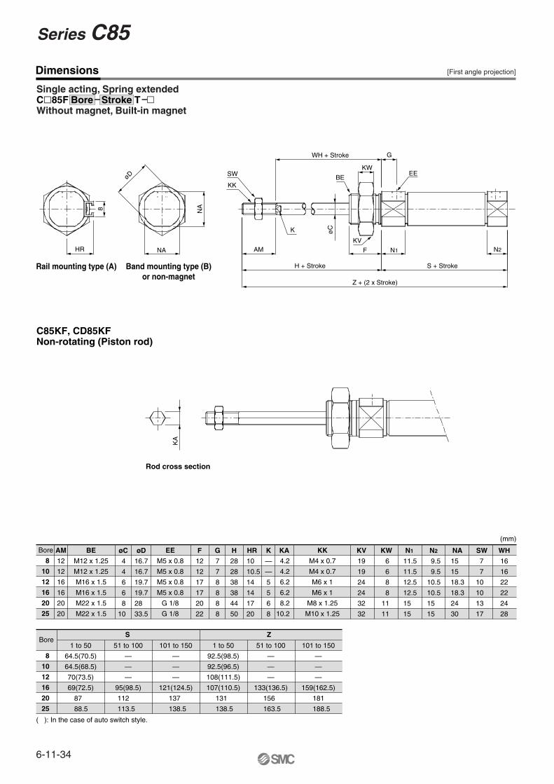
Dimensions
Single acting, Spring extendedC�85FWithout magnet, Built-in magnet
C85KF, CD85KFNon-rotating (Piston rod)
8
10
12
16
20
25
8
10
12
16
20
25
øCAM
12
12
16
16
20
20
BoreS
1 to 50
64.5(70.5)
64.5(68.5)
70(73.5)
69(72.5)
51 to 100
—
—
—
95(98.5)
101 to 150
—
—
—
121(124.5)
1 to 50
92.5(98.5)
92.5(96.5)
108(111.5)
107(110.5)
51 to 100
—
—
—
133(136.5)
Z
101 to 150
—
—
—
159(162.5)
øD
16.7
16.7
19.7
19.7
28
33.5
F
12
12
17
17
20
22
G
7
7
8
8
8
8
H
28
28
38
38
44
50
HR K
—
—
5
5
6
8
KA KV
19
19
24
24
32
32
KW NA
15
15
18.3
18.3
24
30
N1 N2KK
M4 x 0.7
M4 x 0.7
M6 x 1
M6 x 1
M8 x 1.25
M10 x 1.25
EE
M5 x 0.8
M5 x 0.8
M5 x 0.8
M5 x 0.8
G 1/8
G 1/8
BE
M12 x 1.25
M12 x 1.25
M16 x 1.5
M16 x 1.5
M22 x 1.5
M22 x 1.5
WH
16
16
22
22
24
28
SW
( ): In the case of auto switch style.
KA
øD
NA
K
AM F
KV
H + Stroke
øC
N1
Z + (2 x Stroke)
S + Stroke
N2
G
EE
WH + Stroke
KW
BESW
NAHR
8
Rail mounting type (A) Band mounting type (B)or non-magnet
Rod cross section
KK
Bore
4
4
6
6
8
10
10
10.5
14
14
17
20
4.2
4.2
6.2
6.2
8.2
10.2
11.5
11.5
12.5
12.5
15
15
9.5
9.5
10.5
10.5
15
15
7
7
10
10
13
17
6
6
8
8
11
11
181
188.5
156
163.5
131
138.5
137
138.5
87
88.5
112
113.5
Bore Stroke T
[First angle projection]
(mm)
6-11-34
Series C85
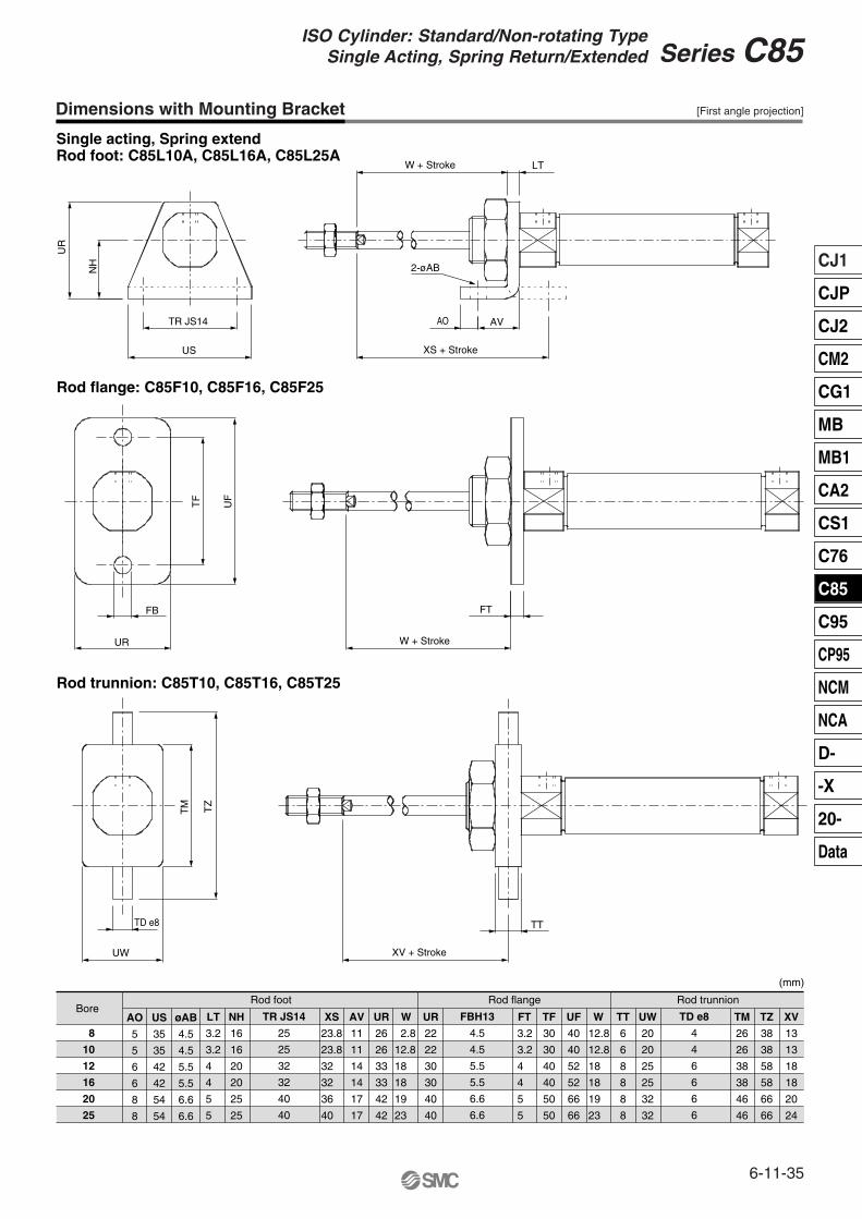
Dimensions with Mounting Bracket
Single acting, Spring extendRod foot: C85L10A, C85L16A, C85L25A
8
10
12
16
20
25
LTAO
5
5
6
6
8
8
US
35
35
42
42
54
54
øAB
4.5
4.5
5.5
5.5
6.6
6.6
NH
16
16
20
20
25
25
XS AV
11
11
14
14
17
17
UR
26
26
33
33
42
42
W UR
22
22
30
30
40
40
FT TF
30
30
40
40
50
50
UF
40
40
52
52
66
66
W TT
6
6
8
8
8
8
UW
20
20
25
25
32
32
FBH13
4.5
4.5
5.5
5.5
6.6
6.6
TD e8
4
4
6
6
6
6
TR JS14
25
25
32
32
40
40
TM
26
26
38
38
46
46
TZ
38
38
58
58
66
66
XV
13
13
18
18
20
24
Rod flange: C85F10, C85F16, C85F25
Rod trunnion: C85T10, C85T16, C85T25
BoreRod foot Rod flange
(mm)
Rod trunnion
UR
FB
TF
UF
W + Stroke
FT
XV + Stroke
TT
UR
NH
TR JS14
US
2-øAB
AO AV
XS + Stroke
W + Stroke LT
UW
TD e8
TM TZ
3.2
3.2
4
4
5
5
23.8
23.8
32
32
36
40
2.8
12.8
18
18
19
23
3.2
3.2
4
4
5
5
12.8
12.8
18
18
19
23
[First angle projection]
6-11-35
CJ1
CJP
CJ2
CM2
CG1
MB
MB1
CA2
CS1
C76
C85
C95
CP95
NCM
NCA
D-
-X
20-
Data
Series C85ISO Cylinder: Standard/Non-rotating Type
Single Acting, Spring Return/Extended
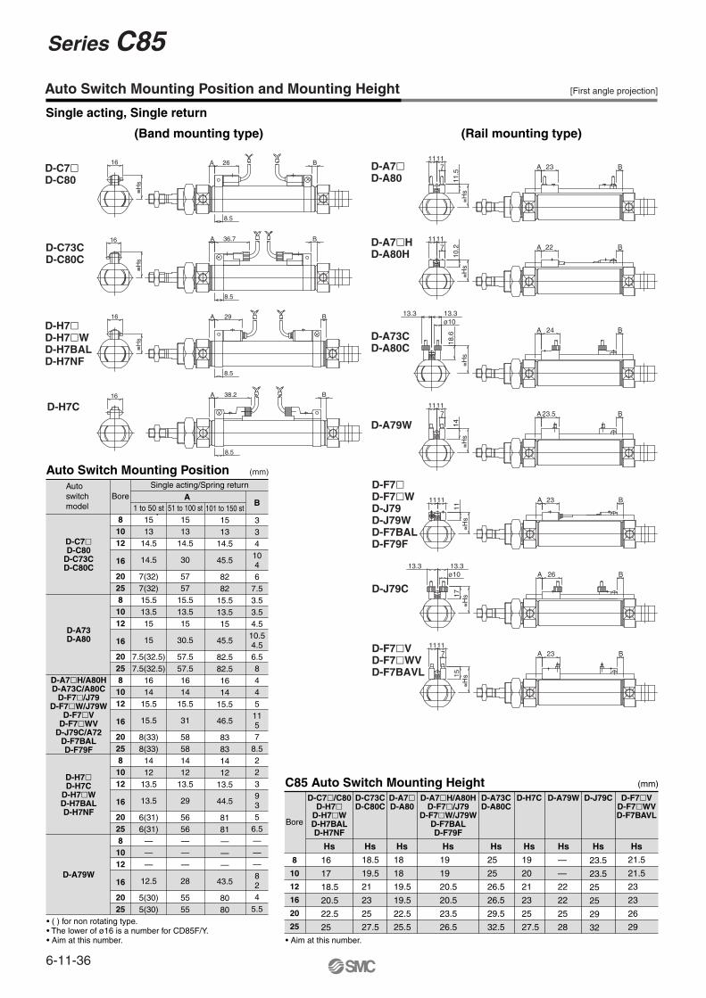
Auto Switch Mounting Position and Mounting Height
Single acting, Single return
(Band mounting type) (Rail mounting type)
[First angle projection]
D-C73CD-C80C
16
≅Hs
A 36.7
8.5
B
D-C7�D-C80
16
≅Hs
A 26
8.5
B
D-H7�D-H7�WD-H7BALD-H7NF
16
≅Hs
A 29 B
8.5
D-H7C16 A
8.5
38.2 B
D-A7�D-A80
23A B1111
≅Hs
11.5
7
D-A7�HD-A80H
22A B1111
≅Hs
10.27
D-A79W23.5A B
1111
≅Hs
14
7
D-A73CD-A80C
A B24
≅Hs
18.6
ø1013.313.3
D-F7�D-F7�WD-J79D-J79WD-F7BALD-F79F
23A B1111
≅Hs
11
D-J79C
17≅H
s
ø1013.313.3
A B26
D-F7�VD-F7�WVD-F7BAVL
23A B1111
7
15≅H
s
(mm)C85 Auto Switch Mounting Height
8
10
12
16
20
25
Bore
• Aim at this number.
D-C7�/C80D-H7�
D-H7�WD-H7BALD-H7NF
Hs
D-A7�D-A80
Hs
D-J79C
Hs
D-F7�VD-F7�WVD-F7BAVL
Hs
D-C73CD-C80C
Hs
18.5
19.5
21
23
25
27.5
18
18
19.5
19.5
22.5
25.5
D-A7�H/A80HD-F7�/J79
D-F7�W/J79WD-F7BALD-F79F
Hs
19
19
20.5
20.5
23.5
26.5
D-A73CD-A80C
Hs
25
25
26.5
26.5
29.5
32.5
D-H7C
Hs
19
20
21
23
25
27.5
D-A79W
Hs
—
—
22
22
25
28
Auto Switch Mounting Position
81012
16
202581012
16
202581012
16
202581012
16
202581012
16
2025
1 to 50 st1513
14.5
14.5
7(32)7(32)15.513.515
15
7.5(32.5)7.5(32.5)
1614
15.5
15.5
8(33)8(33)
1412
13.5
13.5
6(31)6(31)
———
12.5
5(30)5(30)
51 to 100 st1513
14.5
30
5757
15.513.515
30.5
57.557.51614
15.5
31
58581412
13.5
29
5656———
28
5555
101 to 150 st1513
14.5
45.5
8282
15.513.515
45.5
82.582.51614
15.5
46.5
83831412
13.5
44.5
8181———
43.5
8080
3341046
7.53.53.54.510.54.56.584451157
8.5223935
6.5———824
5.5
BoreSingle acting/Spring returnAuto
switch model
• ( ) for non rotating type.• The lower of ø16 is a number for CD85F/Y.• Aim at this number.
D-C7�D-C80
D-C73CD-C80C
D-A73D-A80
D-A7�H/A80HD-A73C/A80C
D-F7�/J79D-F7�W/J79W
D-F7�VD-F7�WV
D-J79C/A72D-F7BALD-F79F
D-H7�D-H7C
D-H7�WD-H7BALD-H7NF
D-A79W
(mm)
AB
16
17
18.5
20.5
22.5
25
23.5
23.5
25
25
29
32
21.5
21.5
23
23
26
29
6-11-36
Series C85
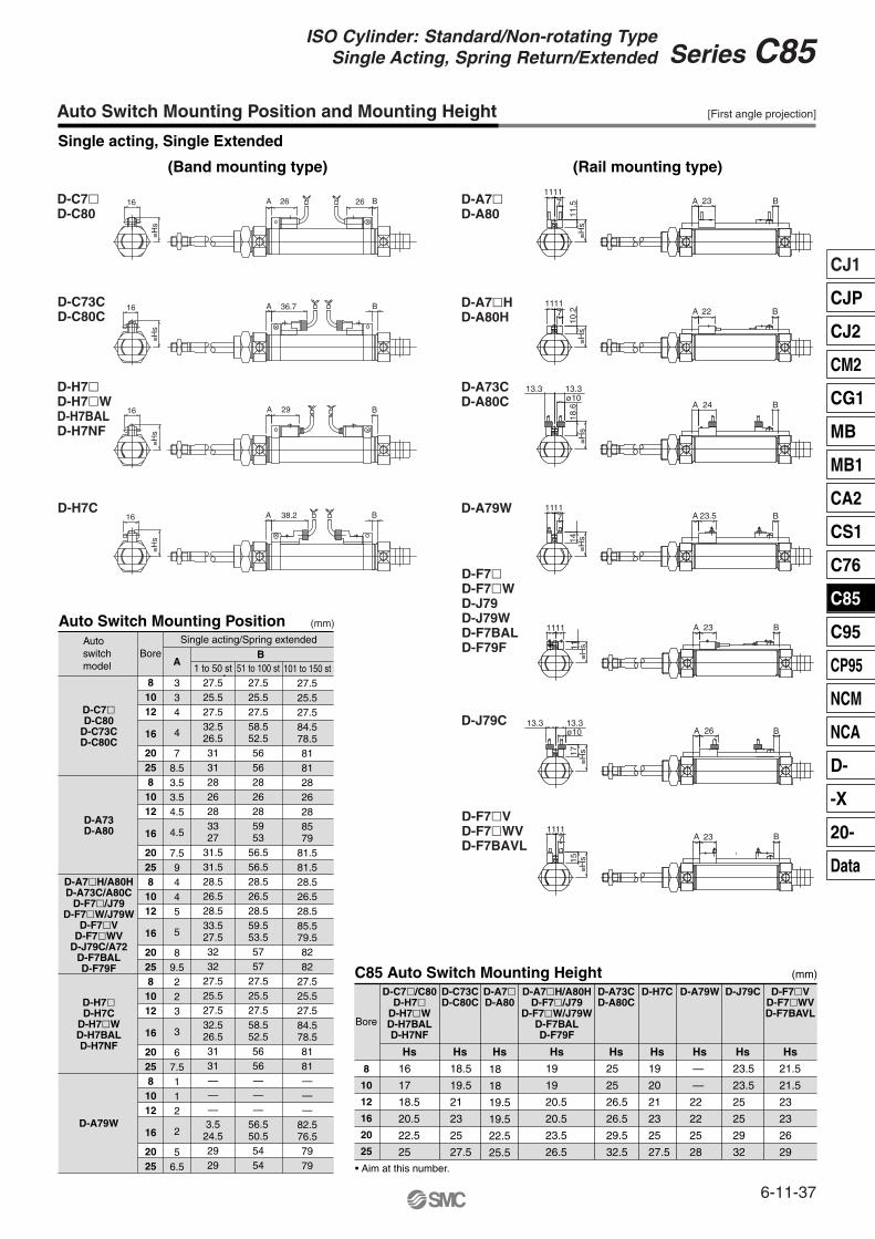
Auto Switch Mounting Position and Mounting Height
Single acting, Single Extended
(Band mounting type) (Rail mounting type)
[First angle projection]
(mm)C85 Auto Switch Mounting Height
8
10
12
16
20
25
Bore
• Aim at this number.
D-C7�/C80D-H7�
D-H7�WD-H7BALD-H7NF
Hs
D-A7�D-A80
Hs
D-J79C
23.5
23.5
25
25
29
32
21.5
21.5
23
23
26
29
D-F7�VD-F7�WVD-F7BAVL
Hs
D-C73CD-C80C
Hs
18.5
19.5
21
23
25
27.5
16
17
18.5
20.5
22.5
25
D-A7�H/A80HD-F7�/J79
D-F7�W/J79WD-F7BALD-F79F
Hs
19
19
20.5
20.5
23.5
26.5
D-A73CD-A80C
Hs
25
25
26.5
26.5
29.5
32.5
D-H7C
Hs
19
20
21
23
25
27.5
D-A79W
Hs Hs
—
—
22
22
25
28
Auto Switch Mounting Position
81012
16
202581012
16
202581012
16
202581012
16
202581012
16
2025
1 to 50 st27.525.527.532.526.531312826283327
31.531.528.526.528.533.527.53232
27.525.527.532.526.53131———3.524.52929
51 to 100 st27.525.527.558.552.556562826285953
56.556.528.526.528.559.553.55757
27.525.527.558.552.55656———
56.550.55454
101 to 150 st27.525.527.584.578.581812826288579
81.581.528.526.528.585.579.58282
27.525.527.584.578.58181———
82.576.57979
334
4
78.53.53.54.5
4.5
7.59445
5
89.5223
3
67.5112
2
56.5
BoreSingle acting/Spring extendedAuto
switch model
D-C7�D-C80
D-C73CD-C80C
D-A73D-A80
D-A7�H/A80HD-A73C/A80C
D-F7�/J79D-F7�W/J79W
D-F7�VD-F7�WV
D-J79C/A72D-F7BALD-F79F
D-H7�D-H7C
D-H7�WD-H7BALD-H7NF
D-A79W
(mm)
BA
16
≅Hs
26A 26 B
16
≅Hs
A 36.7 B
A 38.2 B16
≅Hs
A 29 B16
≅Hs
231111
≅Hs
A B
11.57
221111
A B
≅Hs
10.27
23.51111
A B
≅Hs14
7
A B
≅Hs
18.6
ø1013.3
24
13.3
23A B1111
≅Hs11
A B
17≅H
s
ø1013.313.3
26
231111
7
15≅H
s
A B
18
18
19.5
19.5
22.5
25.5
D-C73CD-C80C
D-C7�D-C80
D-H7�D-H7�WD-H7BALD-H7NF
D-H7C
D-A7�D-A80
D-A7�HD-A80H
D-A79W
D-F7�D-F7�WD-J79D-J79WD-F7BALD-F79F
D-J79C
D-F7�VD-F7�WVD-F7BAVL
D-A73CD-A80C
6-11-37
CJ1
CJP
CJ2
CM2
CG1
MB
MB1
CA2
CS1
C76
C85
C95
CP95
NCM
NCA
D-
-X
20-
Data
Series C85ISO Cylinder: Standard/Non-rotating Type
Single Acting, Spring Return/Extended
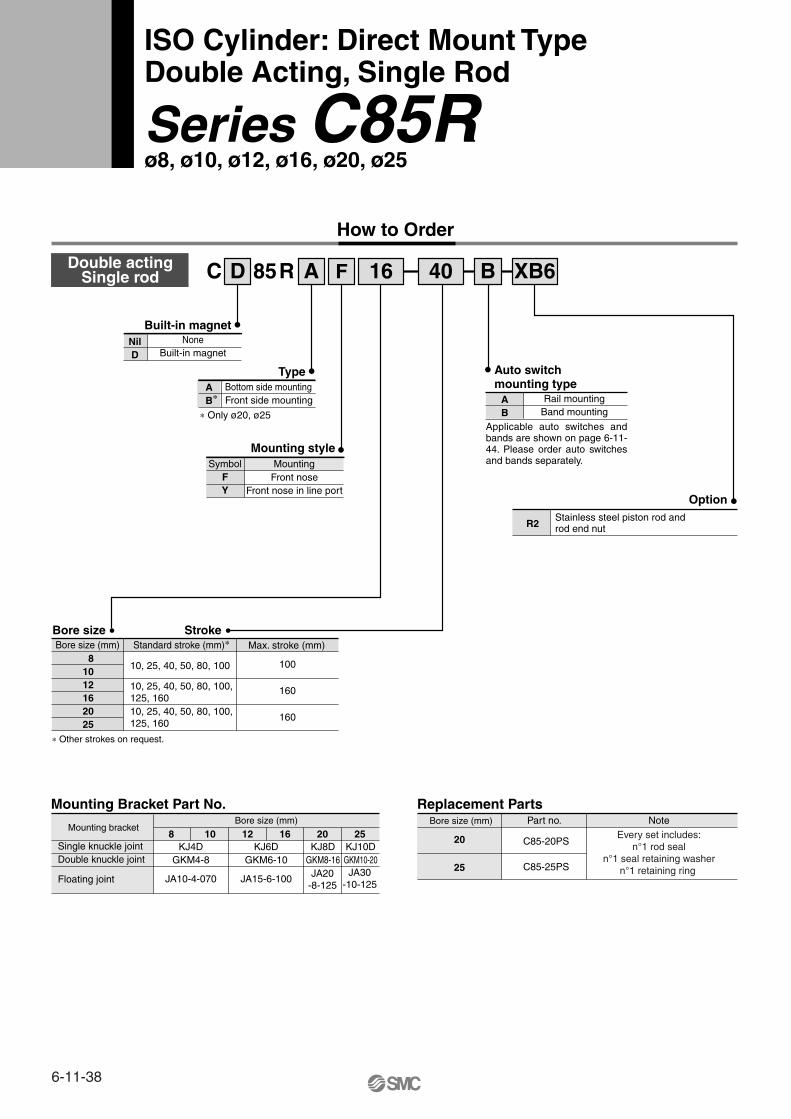
Auto switch mounting type
B Band mountingA Rail mounting
Standard stroke (mm)∗Bore size (mm) Max. stroke (mm)
10, 25, 40, 50, 80, 100
10, 25, 40, 50, 80, 100,125, 16010, 25, 40, 50, 80, 100,125, 160
∗ Other strokes on request.
Option
R2Stainless steel piston rod and rod end nut
Built-in magnet
∗ Only ø20, ø25
NilD
100
160
160
NoneBuilt-in magnet
Type
Bore size Stroke
AB∗
Bottom side mountingFront side mounting
Mounting styleSymbol
FY
MountingFront nose
Front nose in line port
Mounting Bracket Part No.
Mounting bracket8 10 12 16 20 25
JA10-4-070
KJ4DGKM4-8
JA15-6-100
KJ6DGKM6-10
KJ8DGKM8-16
KJ10DGKM10-20JA30
-10-125JA20
-8-125
Bore size (mm)
Replacement Parts
20
25
Part no. Note
C85-20PS
C85-25PS
Every set includes:n°1 rod seal
n°1 seal retaining washern°1 retaining ring
ISO Cylinder: Direct Mount TypeDouble Acting, Single Rod
Series C85Rø8, ø10, ø12, ø16, ø20, ø25
How to Order
Double actingSingle rod D 85RC A F 16 B40 XB6
Bore size (mm)
Applicable auto switches and bands are shown on page 6-11-44. Please order auto switches and bands separately.
81012162025
Single knuckle jointDouble knuckle joint
Floating joint
6-11-38
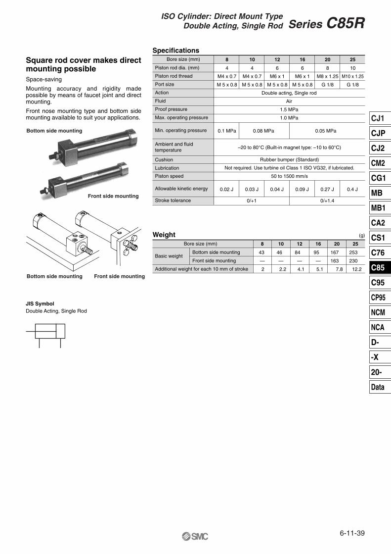
Specifications
Piston rod dia. (mm)
Piston rod thread
Port size
Action
Fluid
Proof pressure
Max. operating pressure
8 10 12 16 20 25
M4 x 0.7 M4 x 0.7 M6 x 1 M6 x 1 M8 x 1.25 M10 x 1.25
4 4 6 6 8 10
M 5 x 0.8 M 5 x 0.8 M 5 x 0.8 M 5 x 0.8 G 1/8 G 1/8
Double acting, Single rod
Air
1.5 MPa
1.0 MPa
–20 to 80°C (Built-in magnet type: –10 to 60°C)
50 to 1500 mm/s
0.02 J 0.03 J 0.04 J 0.09 J 0.27 J 0.4 J
0/+1 0/+1.4
Not required. Use turbine oil Class 1 ISO VG32, if lubricated.
Rubber bumper (Standard)
0.1 MPa 0.08 MPa 0.05 MPaMin. operating pressure
Cushion
Lubrication
Ambient and fluid temperature
Piston speed
Allowable kinetic energy
Stroke tolerance
WeightBore size (mm)
Basic weight
Additional weight for each 10 mm of stroke
25
253
230
12.2
20
167
163
7.8
16
95
5.1
12
84
4.1
10
46
2.2
8
43
2
Bottom side mounting
————Front side mounting
(g)
JIS SymbolDouble Acting, Single Rod
Bottom side mounting
Front side mounting
Bottom side mounting Front side mounting
Square rod cover makes direct mounting possibleSpace-saving
Mounting accuracy and rigidity made possible by means of faucet joint and direct mounting.
Front nose mounting type and bottom side mounting available to suit your applications.
Bore size (mm)
6-11-39
CJ1
CJP
CJ2
CM2
CG1
MB
MB1
CA2
CS1
C76
C85
C95
CP95
NCM
NCA
D-
-X
20-
Data
Series C85RISO Cylinder: Direct Mount Type
Double Acting, Single Rod
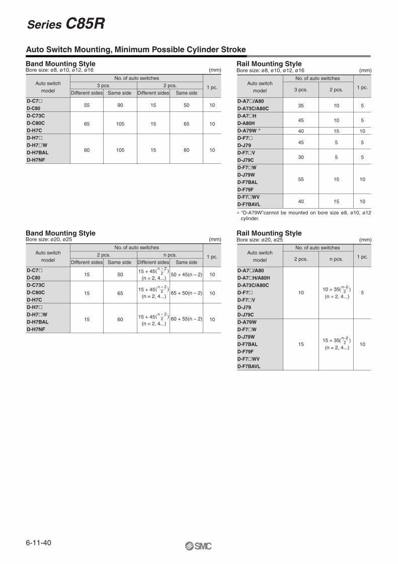
Band Mounting Style
Auto Switch Mounting, Minimum Possible Cylinder Stroke
No. of auto switches
3 pcs. 2 pcs.
Different sides
55
65
60
Same side
90
105
105
Same side
50
65
60
15
15
15
1 pc.
10
10
10
Different sides
Auto switch
model
D-C7�D-C80D-C73CD-C80CD-H7C D-H7�D-H7�WD-H7BALD-H7NF
(mm)Bore size: ø8, ø10, ø12, ø16
35
45
40
45
30
55
40
10
10
15
5
5
15
15
5
5
10
5
5
10
10
Rail Mounting Style
No. of auto switches
3 pcs. 2 pcs.Auto switch
model
D-A7�/A80D-A73C/A80CD-A7�HD-A80HD-A79W ∗
D-F7�D-J79D-F7�VD-J79CD-F7�WD-J79WD-F7BALD-F79FD-F7�WVD-F7BAVL
1 pc.
(mm)Bore size: ø8, ø10, ø12, ø16
Band Mounting Style
No. of auto switches
2 pcs. n pcs.
Different sides
15
15
15
Same side
50
65
60
Same side1 pc.
10
10
10
Different sides
Auto switch
model
D-C7�D-C80D-C73CD-C80CD-H7C D-H7�D-H7�WD-H7BALD-H7NF
(mm)Bore size: ø20, ø25Rail Mounting Style
No. of auto switches
2 pcs. n pcs.Auto switch
model
D-A7�/A80D-A7�H/A80HD-A73C/A80CD-F7�D-F7�VD-J79D-J79CD-A79WD-F7�WD-J79WD-F7BALD-F79FD-F7�WVD-F7BAVL
1 pc.
(mm)Bore size: ø20, ø25
50 + 45(n – 2)
65 + 50(n – 2)
60 + 55(n – 2)
15 + 45(n = 2, 4...)
( n – 2 )2
15 + 45(n = 2, 4...)
( n – 2 )2
15 + 45(n = 2, 4...)
( n – 2 )2
)10 + 35(n = 2, 4...)
( n–22
)15 + 35(n = 2, 4...)
( n–22
10
15
5
10
∗ “D-A79W”cannot be mounted on bore size ø8, ø10, ø12 cylinder.
6-11-40
Series C85R
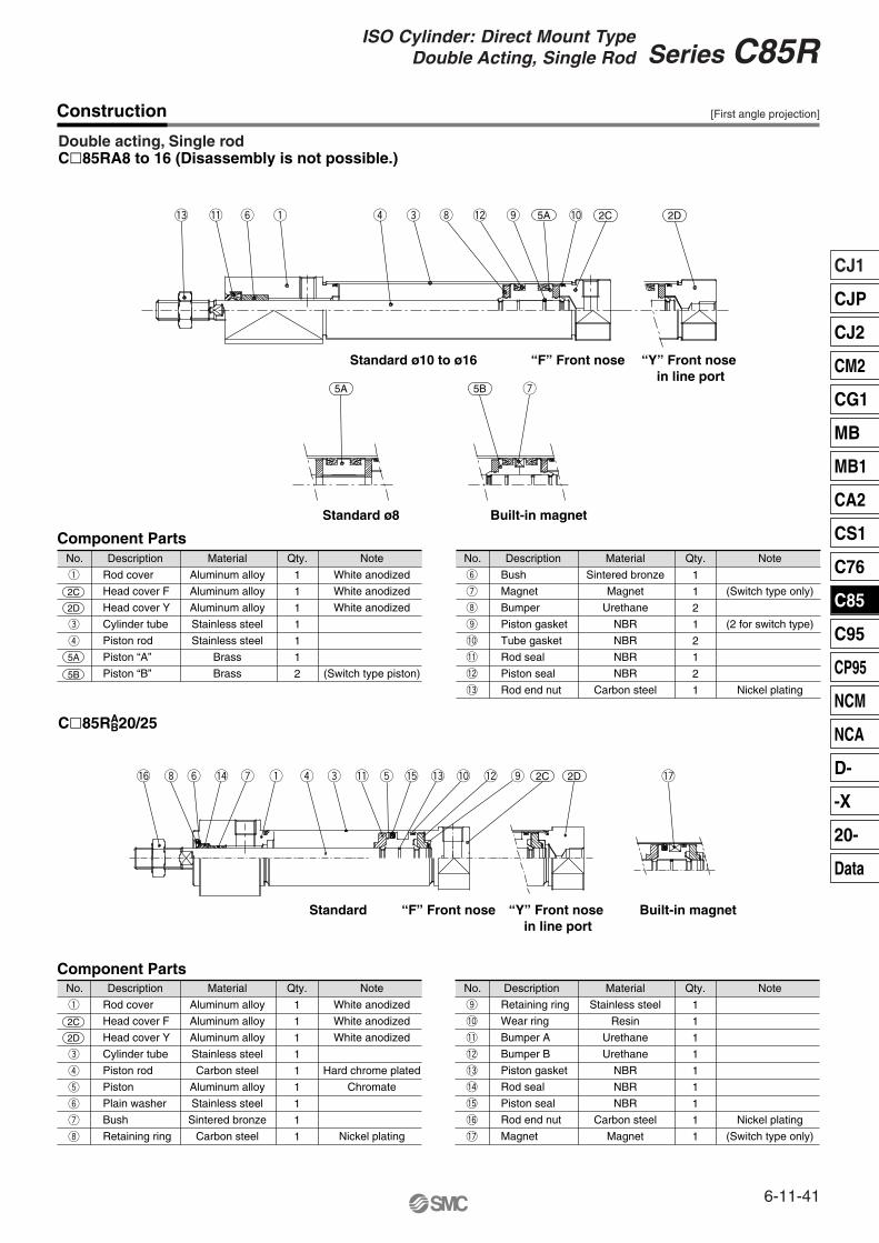
Construction
Double acting, Single rodC�85RA8 to 16 (Disassembly is not possible.)
No.
Rod cover
Head cover F
Head cover Y
Cylinder tube
Piston rod
Piston “A”
Piston “B”
Material
Aluminum alloy
Aluminum alloy
Aluminum alloy
Stainless steel
Stainless steel
Brass
Brass
1
1
1
1
1
1
2
Note
White anodized
White anodized
White anodized
(Switch type piston)
Component Parts
2C
2D
5A
5B
Description Qty.
q
e
r
No.
Bush
Magnet
Bumper
Piston gasket
Tube gasket
Rod seal
Piston seal
Rod end nut
Material
Sintered bronze
Magnet
Urethane
NBR
NBR
NBR
NBR
Carbon steel
1
1
2
1
2
1
2
1
Note
(Switch type only)
(2 for switch type)
Nickel plating
Description Qty.
y
u
i
o
!0
!1
!2
!3
No.
Rod cover
Head cover F
Head cover Y
Cylinder tube
Piston rod
Piston
Plain washer
Bush
Retaining ring
Material
Aluminum alloy
Aluminum alloy
Aluminum alloy
Stainless steel
Carbon steel
Aluminum alloy
Stainless steel
Sintered bronze
Carbon steel
1
1
1
1
1
1
1
1
1
Note
White anodized
White anodized
White anodized
Hard chrome plated
Chromate
Nickel plating
Component Parts
2C
2D
Description Qty.
q
e
r
t
y
u
i
No.
Retaining ring
Wear ring
Bumper A
Bumper B
Piston gasket
Rod seal
Piston seal
Rod end nut
Magnet
Material
Stainless steel
Resin
Urethane
Urethane
NBR
NBR
NBR
Carbon steel
Magnet
1
1
1
1
1
1
1
1
1
Note
Nickel plating
(Switch type only)
Description Qty.
o
!0
!1
!2
!3
!4
!5
!6
!7
C�85RAB20/25
!3 !1 y q r e i !2 o !0
u5A 5B
2C5A
Standard ø10 to ø16 “F” Front nose “Y” Front nose in line port
Built-in magnetStandard ø8
Standard “F” Front nose “Y” Front nose in line port
Built-in magnet
2D
!6 i y !4 u q r e !1 t !5 !3 !0 !2 o 2C 2D !7
[First angle projection]
6-11-41
CJ1
CJP
CJ2
CM2
CG1
MB
MB1
CA2
CS1
C76
C85
C95
CP95
NCM
NCA
D-
-X
20-
Data
Series C85RISO Cylinder: Direct Mount Type
Double Acting, Single Rod
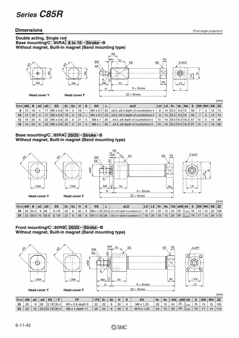
Dimensions
Double acting, Single rodBase mounting/C�85RAF
YWithout magnet, Built-in magnet (Band mounting type)
Bore AM
12
12
16
16
B
16
16
20
20
øC
4
4
6
6
øD
17
17
20
20
EE
M5 x 0.8
M5 x 0.8
M5 x 0.8
M5 x 0.8
G1
19
19
25
25
G2
5
5
6
6
H
16
16
21
21
K
—
—
5
5
KK
M4 x 0.7
M4 x 0.7
M6 x 1
M6 x 1
L
23
23
26
26
øLD
ø3.5, ø6.5 depth of counterbore 4
ø3.5, ø6.5 depth of counterbore 4
ø4.5, ø8 depth of counterbore 5
ø4.5, ø8 depth of counterbore 5
LH LX
14
14
16
16
N1
23.5
23.5
29.5
29.5
N2 NA S
58
58
67
67
SW WH
4
4
5
5
XB
12
12
16
16
ZZ
74
74
88
88
øD
NA
NA
øD
NA
NA
SW
KK
WH
XB
KAM
H
øC
N1
G1EE
S + Stroke
ZZ + Stroke
G2EE
N2 LX
L
LH
B
2-øLD
Head cover Y Head cover F
20
25
AM
20
22
B
30.3
36.6
øC øD EE
G 1/8
G 1/8
G1
22
22
G2
8
8
H
30
36
K
6
8
KK
M8 x 1.25
M10 x 1.25
L øLD
ø5.5, ø9.5 depth of counterbore 6.5
ø6.6, ø11 depth of counterbore 7.5
LH
15
18
LX
21
25
N1
29
29
N2
15
15
�NA
24
30
øND h8 S
76
79
SW
13
17
WH
10
14
XB
22
26
ZZ
106
115
Base mounting/C�85RAF Y
Without magnet, Built-in magnet (Band mounting type)
øD
�NA
øD
�NA
øN
D
øC
SW
XB
WH G1 EF EE G2 2-øLD
N2
KK
K
AM
H
N1
S + Stroke
ZZ + Stroke
3
B
LH
LX
L
20
26
0–0.033 0–0.033
Bore AM
20
22
øC øD EE
G 1/8
G 1/8
�F
30.4
36.4
FF
M5 x 0.8 depth 9
M6 x 1 depth 11
�FX
22
26
G1
22
22
G2
8
8
H
30
36
K
6
8
KK
M8 x 1.25
M10 x 1.25
N1
29
29
N2
15
15
�NA
24
30
øND h8 S
76
79
SW
13
17
WH
10
14
ZZ
106
115
Front mounting/C�85RBF Y
Without magnet, Built-in magnet (Band mounting type)
øD
�NA
øD
�NA
øN
D
øC
SWWH G1 EE
KK
K
AM
H
3 N1
S + Stroke
N2
ZZ + Stroke
EE G2 4-øFF
�FX
�F
20
26
0–0.033 0–0.033
Head cover Y Head cover F
Head cover Y Head cover F
8
10
12
16
8
8
10
10
7
7
10
10
9.5
9.5
10.5
10.5
15
15
18.3
18.3
Bore
8
10
28
33.5
33.5
39
20
25
8
10
28
33.5
8 to 16 Stroke B
20/25 Stroke B
20/25 Stroke B
[First angle projection]
(mm)
(mm)
(mm)
6-11-42
Series C85R
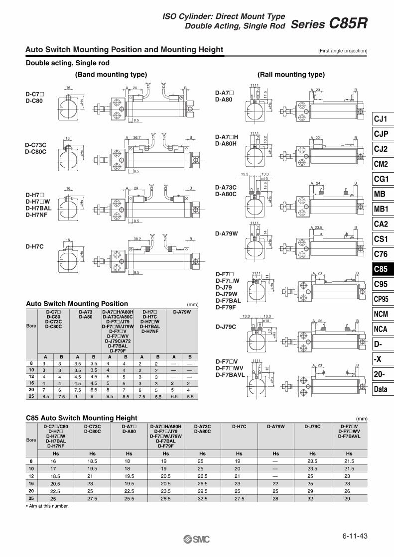
Auto Switch Mounting Position and Mounting Height
Double acting, Single rod
(Band mounting type) (Rail mounting type)
[First angle projection]
(mm)
Auto Switch Mounting Position
C85 Auto Switch Mounting Height
81012162025
A B A B A B A B A B
Bore
8
10
12
16
20
25
Bore
• Aim at this number.
D-C7�D-C80
D-C73CD-C80C
D-A73D-A80
D-A7�H/A80HD-A73C/A80C
D-F7�/J79D-F7�W/J79W
D-F7�VD-F7�WV
D-J79C/A72D-F7BALD-F79F
D-C7�/C80D-H7�
D-H7�WD-H7BALD-H7NF
D-A7�H/A80HD-F7�/J79
D-F7�W/J79WD-F7BALD-F79F
D-F7�VD-F7�WVD-F7BAVL
D-C73CD-C80C
D-A73CD-A80C
D-H7C D-A79W D-J79CD-A7�D-A80
D-H7�D-H7C
D-H7�WD-H7BALD-H7NF
D-A79W
(mm)
D-A7�D-A80
23 BA
≅Hs
1111
11.5
7
23.5 BA
D-A79W
≅Hs
1111
14
7
D-A7�HD-A80H
≅Hs
1111
10.27 22 BA
D-A73CD-A80C
≅Hs
18.6
ø1013.313.3
B24A
D-F7�D-F7�WD-J79D-J79WD-F7BALD-F79F
23 BA1111≅H
s11
D-J79C
17≅H
s
ø1013.313.3
BA 26
D-F7�VD-F7�WVD-F7BAVL
11117
15≅H
s
23 BA
D-C7�D-C80
26
8.5
A B16
≅Hs
D-C73CD-C80C
16
≅Hs
36.7
8.5
A B
D-H7�D-H7�WD-H7BALD-H7NF
16
≅Hs
29
8.5
A B
D-H7C
8.5
38.2 B16
≅Hs
Hs HsHs Hs Hs Hs Hs Hs Hs
18.5
19.5
21
23
25
27.5
18
18
19.5
19.5
22.5
25.5
19
19
20.5
20.5
23.5
26.5
25
25
26.5
26.5
29.5
32.5
19
20
21
23
25
27.5
—
—
—
22
25
28
23.5
23.5
25
25
29
32
21.5
21.5
23
23
26
29
16
17
18.5
20.5
22.5
25
334478.5
334467.5
3.53.54.54.57.59
3.53.54.54.56.58
445589.5
445578.5
223367.5
223356.5
———256.5
———245.5
6-11-43
CJ1
CJP
CJ2
CM2
CG1
MB
MB1
CA2
CS1
C76
C85
C95
CP95
NCM
NCA
D-
-X
20-
Data
Series C85RISO Cylinder: Direct Mount Type
Double Acting, Single Rod
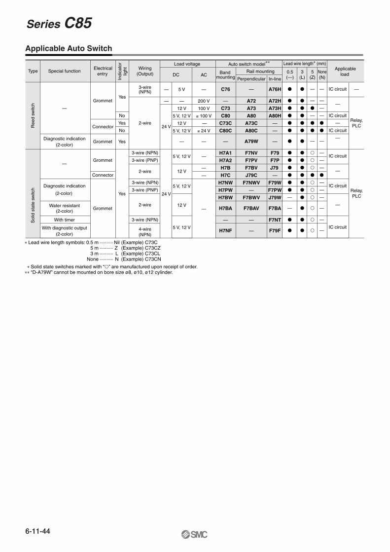
Type Special function
—
Diagnostic indication(2-color)
—
Diagnostic indication
(2-color)
Water resistant(2-color)
With timer
With diagnostic output(2-color)
Ree
d sw
itch
Sol
id s
tate
sw
itch
Electricalentry
Grommet
Connector
Indi
cato
rlig
ht
Yes
No
Yes
Yes
No
Grommet
Grommet
Connector
Grommet
Yes
4-wire(NPN)
Wiring(Output)
3-wire(NPN)
2-wire
3-wire (NPN)
3-wire (PNP)
2-wire
3-wire (NPN)
3-wire (PNP)
2-wire
3-wire (NPN)
Load voltage
DC AC
Auto switch model∗∗
Band mounting
C76
—
C73
C80
C73C
C80C
—
H7A1
H7A2
H7B
H7C
H7NW
H7PW
H7BW
H7BA
—
H7NF
—
—
24 V
24 V
5 V
—
12 V
5 V, 12 V
12 V
5 V, 12 V
—
5 V, 12 V
12 V
5 V, 12 V
12 V
5 V, 12 V
—
200 V
100 V
≤ 100 V
—
≤ 24 V
—
—
—
—
—
Rail mounting
Perpendicular
—
A72
A73
A80
A73C
A80C
A79W
F7NV
F7PV
F7BV
J79C
F7NWV
—
F7BWV
F7BAV
—
—
A76H
A72H
A73H
A80H
—
—
—
F79
F7P
J79
—
F79W
F7PW
J79W
F7BA
F7NT
F79F
Lead wire length∗ (mm)
0.5(—)
3(L)
5(Z)
None(N)
Applicableload
IC circuit
—
IC circuit
—
IC circuit
—
IC circuit
—
IC circuit
—
IC circuit
Relay,PLC
—
Relay,PLC
In-line
∗ Lead wire length symbols: 0.5 m ·········· Nil (Example) C73C5 m ·········· Z (Example) C73CZ3 m ·········· L (Example) C73CL
None ·········· N (Example) C73CN
∗ Solid state switches marked with “�” are manufactured upon receipt of order. ∗∗ “D-A79W” cannot be mounted on bore size ø8, ø10, ø12 cylinder.
�
�
�
�
�
�
�
�
�
�
�
�
�
—
—
�
�
�
�
�
�
�
�
�
�
�
�
�
�
�
�
�
�
�
—
—
�
—
�
�
—
�
�
�
�
�
�
�
�
�
�
—
—
—
—
�
�
—
—
—
—
�
—
—
—
—
—
—
Applicable Auto Switch
6-11-44
Series C85
6-11-44
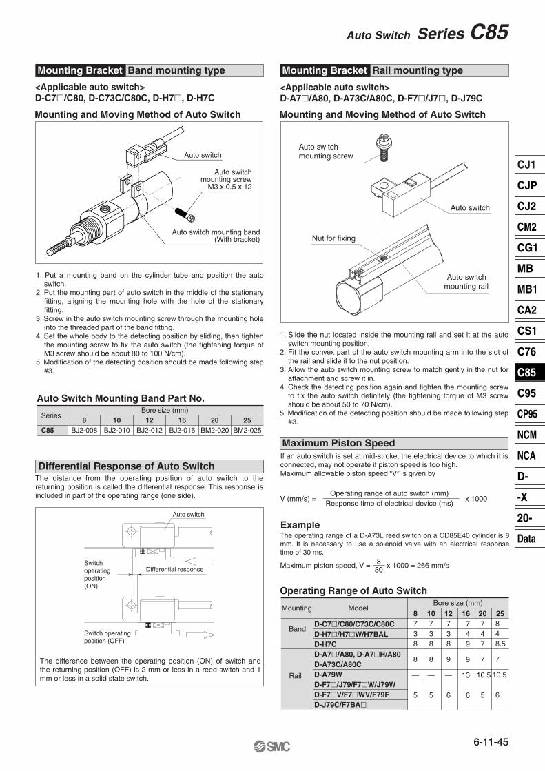
Auto switch
<Applicable auto switch>D-C7�/C80, D-C73C/C80C, D-H7�, D-H7C
<Applicable auto switch>D-A7�/A80, D-A73C/A80C, D-F7�/J7�, D-J79C
Mounting and Moving Method of Auto SwitchMounting and Moving Method of Auto Switch
Auto switch mounting screw
Nut for fixing
Auto switch mounting rail
Maximum Piston Speed
ExampleThe operating range of a D-A73L reed switch on a CD85E40 cylinder is 8 mm. It is necessary to use a solenoid valve with an electrical response time of 30 ms.
Operating Range of Auto Switch
1. Slide the nut located inside the mounting rail and set it at the auto switch mounting position.
2. Fit the convex part of the auto switch mounting arm into the slot of the rail and slide it to the nut position.
3. Allow the auto switch mounting screw to match gently in the nut for attachment and screw it in.
4. Check the detecting position again and tighten the mounting screw to fix the auto switch definitely (the tightening torque of M3 screw should be about 50 to 70 N/cm).
5. Modification of the detecting position should be made following step #3.
1. Put a mounting band on the cylinder tube and position the auto switch.
2. Put the mounting part of auto switch in the middle of the stationary fitting, aligning the mounting hole with the hole of the stationary fitting.
3. Screw in the auto switch mounting screw through the mounting hole into the threaded part of the band fitting.
4. Set the whole body to the detecting position by sliding, then tighten the mounting screw to fix the auto switch (the tightening torque of M3 screw should be about 80 to 100 N/cm).
5. Modification of the detecting position should be made following step #3.
MountingBore size (mm)
Auto Switch Mounting Band Part No.
SeriesBore size (mm)
8BJ2-008C85
The difference between the operating position (ON) of switch and the returning position (OFF) is 2 mm or less in a reed switch and 1 mm or less in a solid state switch.
Auto switch
Differential responseSwitchoperatingposition(ON)
Switch operatingposition (OFF)
The distance from the operating position of auto switch to the returning position is called the differential response. This response is included in part of the operating range (one side).
If an auto switch is set at mid-stroke, the electrical device to which it is connected, may not operate if piston speed is too high.Maximum allowable piston speed “V” is given by
10BJ2-010
12BJ2-012
16BJ2-016
20BM2-020
25BM2-025
V (mm/s) =Operating range of auto switch (mm)
Response time of electrical device (ms)x 1000
Maximum piston speed, V = x 1000 = 266 mm/s830
D-C7�/C80/C73C/C80CD-H7�/H7�W/H7BALD-H7CD-A7�/A80, D-A7�H/A80D-A73C/A80CD-A79WD-F7�/J79/F7�W/J79WD-F7�V/F7�WV/F79FD-J79C/F7BA�
Model8738
8
—
5
10738
8
—
5
12738
9
—
6
20747
7
10.5
5
Band mounting typeMounting Bracket Rail mounting typeMounting Bracket
Auto switchmounting screw
M3 x 0.5 x 12
Auto switch
Auto switch mounting band(With bracket)
Differential Response of Auto Switch
Band
Rail
16749
9
13
6
25848.5
7
10.5
6
6-11-45
CJ1
CJP
CJ2
CM2
CG1
MB
MB1
CA2
CS1
C76
C85
C95
CP95
NCM
NCA
D-
-X
20-
Data
Auto Switch Series C85
6-11-45
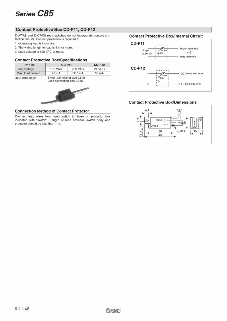
D-A7/A8 and D-C7/C8 reed switches do not incorporate contact pro-tection circuits. Contact protection is required if:1. Operating load is inductive.2. The wiring length to load is 5 m or more.3. Load voltage is 100 VAC or more.
Connect lead wires from reed switch to those on protector box indicated with “switch”. Length of lead between switch body and protector should be less than 1 m.
Contact Protective Box/SpecificationsPart no. CD-P11 CD-P12
Load voltage 100 VAC 200 VAC 24 VDCMax. load current 25 mA 12.5 mA 50 mA
Lead wire lengh ···········
Contact Protective Box/Internal Circuit
Chokecoil
(+) Brown lead wire
(–) Blue lead wire
CD-P12
Surgeabsorber
Chokecoil
Brown lead wire
Blue lead wire
CD-P11
Contact Protective Box/Dimensions
Connection Method of Contact Protector
switc
h
15,5
CD-P
VOLT
3846
4,4
3,4
9 18
ø3.4
Switch connecting side 0.5 mLoad connecting side 0.5 m
Contact Protective Box CD-P11, CD-P12
(~)
6-11-46
Series C85
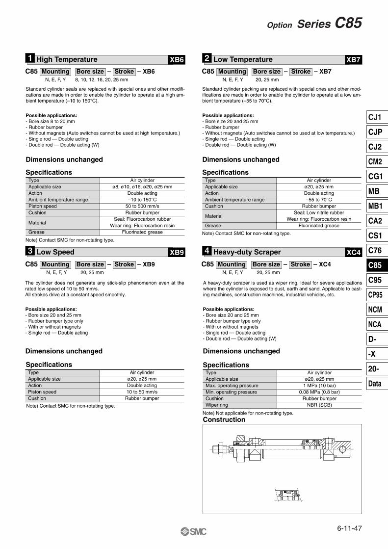
N, E, F, Y 8, 10, 12, 16, 20, 25 mm
Standard cylinder seals are replaced with special ones and other modifi-cations are made in order to enable the cylinder to operate at a high am-bient temperature (–10 to 150°C).
Possible applications:- Bore size 8 to 20 mm- Rubber bumper- Without magnets (Auto switches cannot be used at high temperature.)- Single rod — Double acting- Double rod — Double acting (W)
Dimensions unchanged
SpecificationsTypeApplicable sizeActionAmbient temperature rangePiston speedCushion
Grease
Material
Air cylinderø8, ø10, ø16, ø20, ø25 mm
Double acting–10 to 150°C
50 to 500 mm/sRubber bumper
Seal: Fluorocarbon rubberWear ring: Fluorocarbon resin
Fluorinated grease
N, E, F, Y 20, 25 mm
Possible applications:- Bore size 20 and 25 mm- Rubber bumper- Without magnets (Auto switches cannot be used at low temperature.)- Single rod — Double acting- Double rod — Double acting (W)
Dimensions unchanged
SpecificationsTypeApplicable sizeActionAmbient temperature rangeCushion
Grease
Material
Air cylinderø20, ø25 mmDouble acting–55 to 70°C
Rubber bumperSeal: Low nitrile rubber
Wear ring: Fluorocarbon resinFluorinated grease
Standard cylinder packing are replaced with special ones and other mod-ifications are made in order to enable the cylinder to operate at a low am-bient temperature (–55 to 70°C).
C85 Mounting Bore size – Stroke – XB6
C85 Mounting Bore size – Stroke – XB9
C85 Mounting Bore size – Stroke – XB7
1 High Temperature XB6 2 Low Temperature XB7
3 Low Speed XB9 4 Heavy-duty Scraper XC4
N, E, F, Y 20, 25 mm
C85 Mounting Bore size – Stroke – XC4N, E, F, Y 20, 25 mm
The cylinder does not generate any stick-slip phenomenon even at the rated low speed of 10 to 50 mm/s. All strokes drive at a constant speed smoothly.
A heavy-duty scraper is used as wiper ring. Ideal for severe applications where the cylinder is exposed to dust, earth and sand. Applicable to cast-ing machines, construction machines, industrial vehicles, etc.
Possible applications:- Bore size 20 and 25 mm- Rubber bumper type only- With or without magnets- Single rod — Double acting
Dimensions unchanged
SpecificationsTypeApplicable sizeActionPiston speedCushion
Note) Contact SMC for non-rotating type.
Air cylinderø20, ø25 mmDouble acting10 to 50 mm/s
Rubber bumper
Possible applications:- Bore size 20 and 25 mm- Rubber bumper type only- With or without magnets- Single rod — Double acting- Double rod — Double acting (W)
Dimensions unchanged
Specifications
Construction
TypeApplicable sizeMax. operating pressureMin. operating pressureCushionWiper ring
Air cylinderø20, ø25 mm
1 MPa (10 bar)0.08 MPa (0.8 bar)
Rubber bumperNBR (SCB)
Note) Contact SMC for non-rotating type.Note) Contact SMC for non-rotating type.
Note) Not applicable for non-rotating type.
6-11-47
CJ1
CJP
CJ2
CM2
CG1
MB
MB1
CA2
CS1
C76
C85
C95
CP95
NCM
NCA
D-
-X
20-
Data
Option Series C85