iso metric screw threadszb.guaihou.com/stdpool/bs 3643-1-2007 iso metric screw... · 2008-05-01...
TRANSCRIPT

BS 3643-1:2007
ISO metric screw threadsPart 1: Principles and basic dataICS 21.040.10
NO COPYING WITHOUT BSI PERMISSION EXCEPT AS PERMITTED BY COPYRIGHT LAW
BRITISH STANDARD
Licensed copy:PONTYPRIDD COLLEGE, 05/01/2008, Uncontrolled Copy, © BSI

Publishing and copyright informationThe BSI copyright notice displayed in this document indicates when the document was last issued.
© BSI 2007
ISBN 978 0 580 57924 0
The following BSI references relate to the work on this standard:Committee reference FME/9Draft for comment 07/30158486 DC
Publication historyFirst published June 1963Second edition, March 1981Third edition, November 2007
Amendments issued since publication
Amd. no. Date Text affected
BS 3643-1:2007
Licensed copy:PONTYPRIDD COLLEGE, 05/01/2008, Uncontrolled Copy, © BSI
www.bzfxw.com
© BSI 2007 • i
BS 3643-1:2007
ContentsForeword iii
1 Scope 12 Normative references 13 Terms and definitions and symbols 14 Basic profile 25 General plan 56 Basic dimensions 87 Tolerances – Principles and basic data 188 Tolerances – Deviations for constructional threads 359 Tolerances – Limits of sizes for hot-dip galvanized external screw
threads to mate with internal screw threads tapped with tolerance position H or G after galvanizing 53
10 Tolerances – Limits of sizes for internal screw threads to mate with hot-dip galvanized external screw threads with maximum size of tolerance position h before galvanizing 55
AnnexesAnnex A (informative) Notes for guidance 60Annex B (informative) Examples of calculations of limits of size for metric screw threads 65
Bibliography 68
List of figuresFigure 1 – Basic profile of ISO metric thread 3Figure 2 – Basic dimensions 8Figure 3 – Tolerance positions with respect to zero line (basic size) 19Figure 4 – Internal threads with tolerance position G 21Figure 5 – Internal threads with tolerance position H 22Figure 6 – External threads with tolerance positions e, f and g 22Figure 7 – External threads with tolerance position h 23Figure 8 – External root profile 31Figure A.1 – Maximum material profiles for internal and external threads 61Figure B.1 – Illustration of limits of size for external thread (see Example 1) 66
List of tablesTable 1 – Basic profile dimensions 4Table 2 – Maximum nominal diameter 5Table 3 – Diameter/pitch combinations 6Table 4 – Basic dimensions 9Table 5 – Fundamental deviations for internal threads and external threads 24Table 6 – Lengths of thread engagement 25Table 7 – Minor diameter tolerances of internal threads (TD1) 26Table 8 – Major diameter tolerances of external threads (Td) 27Table 9 – Pitch diameter tolerances of internal threads (TD2) 28Table 10 – Pitch diameter tolerances of external threads (Td2) 29Table 11 – Minimum root radii 31Table 12 – Recommended tolerance classes for internal threads 32Table 13 – Recommended tolerance classes for external threads 32Table 14 – Deviations 36Table 15 – Deviations for hot-dip galvanized external threads 54
Licensed copy:PONTYPRIDD COLLEGE, 05/01/2008, Uncontrolled Copy, © BSI

www.bzfxw.com
BS 3643-1:2007
ii • © BSI 2007
Table 16 – External thread limits for tolerance class 6az 55Table 17 – Deviations for internal threads to mate with hot-dip galvanized external threads 57Table 18 – Internal screw thread limits for tolerance class 6AZ 58Table 19 – Internal screw thread limits for tolerance class 6AX 59Table A.1 – Nominal stress areas for external screw threads – Coarse series 63Table A.2 – Nominal stress areas for external screw threads – Fine series 64
Summary of pages
This document comprises a front cover, an inside front cover, pages i to iv, pages 1 to 68, an inside back cover and a back cover.
Licensed copy:PONTYPRIDD COLLEGE, 05/01/2008, Uncontrolled Copy, © BSI
www.bzfxw.com
© BSI 2007 • iii
BS 3643-1:2007
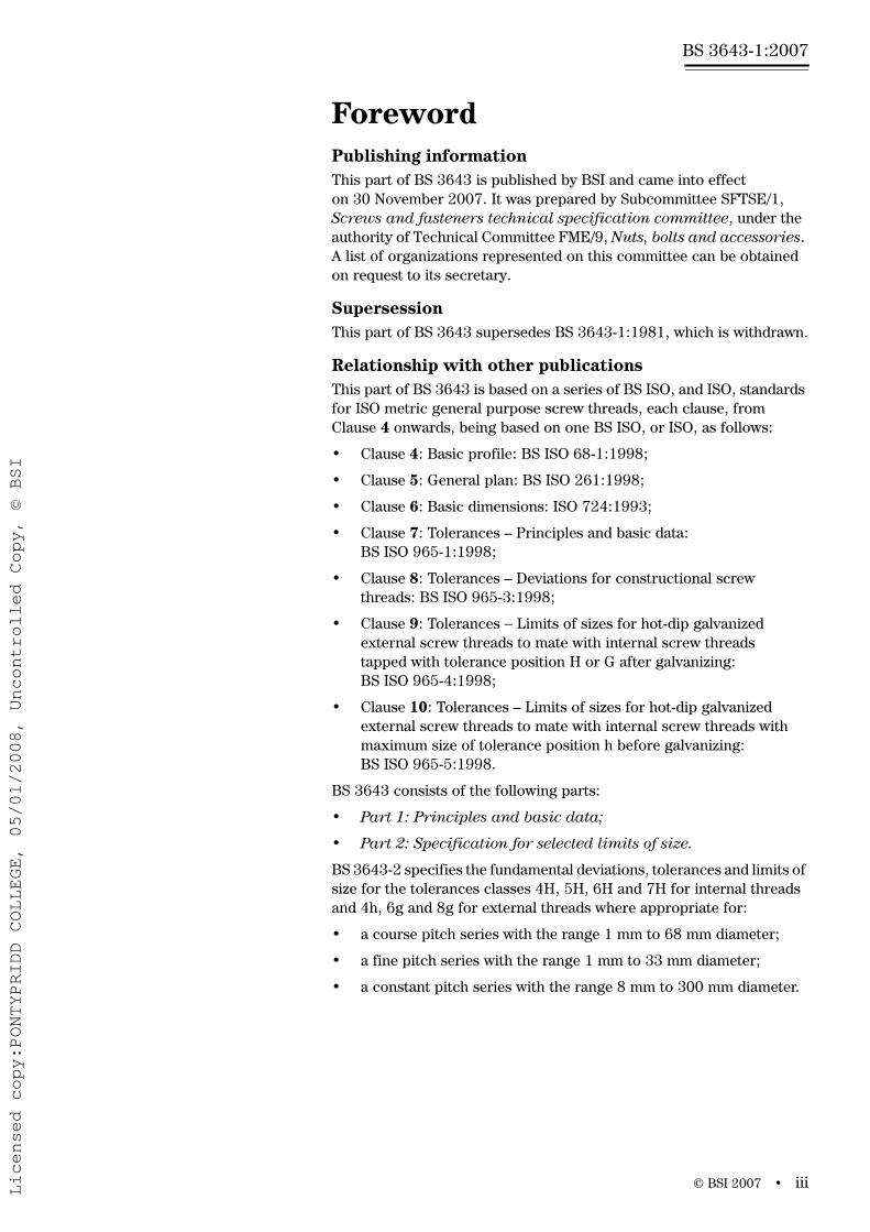
ForewordPublishing informationThis part of BS 3643 is published by BSI and came into effect on 30 November 2007. It was prepared by Subcommittee SFTSE/1, Screws and fasteners technical specification committee, under the authority of Technical Committee FME/9, Nuts, bolts and accessories. A list of organizations represented on this committee can be obtained on request to its secretary.
SupersessionThis part of BS 3643 supersedes BS 3643-1:1981, which is withdrawn.
Relationship with other publicationsThis part of BS 3643 is based on a series of BS ISO, and ISO, standards for ISO metric general purpose screw threads, each clause, from Clause 4 onwards, being based on one BS ISO, or ISO, as follows:
• Clause 4: Basic profile: BS ISO 68-1:1998;
• Clause 5: General plan: BS ISO 261:1998;
• Clause 6: Basic dimensions: ISO 724:1993;
• Clause 7: Tolerances – Principles and basic data: BS ISO 965-1:1998;
• Clause 8: Tolerances – Deviations for constructional screw threads: BS ISO 965-3:1998;
• Clause 9: Tolerances − Limits of sizes for hot-dip galvanized external screw threads to mate with internal screw threads tapped with tolerance position H or G after galvanizing: BS ISO 965-4:1998;
• Clause 10: Tolerances – Limits of sizes for hot-dip galvanized external screw threads to mate with internal screw threads with maximum size of tolerance position h before galvanizing: BS ISO 965-5:1998.
BS 3643 consists of the following parts:
• Part 1: Principles and basic data;
• Part 2: Specification for selected limits of size.
BS 3643-2 specifies the fundamental deviations, tolerances and limits of size for the tolerances classes 4H, 5H, 6H and 7H for internal threads and 4h, 6g and 8g for external threads where appropriate for:
• a course pitch series with the range 1 mm to 68 mm diameter;
• a fine pitch series with the range 1 mm to 33 mm diameter;
• a constant pitch series with the range 8 mm to 300 mm diameter.
Licensed copy:PONTYPRIDD COLLEGE, 05/01/2008, Uncontrolled Copy, © BSI

www.bzfxw.com
BS 3643-1:2007
iv • © BSI 2007
Information about this documentThis part of BS 3643 has been revised to bring it up to date. The 1981 edition of the standard was based on ISO 68:1963, ISO 261:1973, ISO 724:1968, ISO 965-1:1980 and ISO 965-3:1980. These standards have all been withdrawn and superseded and this part of BS 3643 has been revised to reflect the latest editions of these standards (see above).
Two extra clauses have been added to this revision, based on BS ISO 965-4:1998 and BS ISO 965-5:1998, respectively.
This part of BS 3643 does not include a clause based on BS ISO 965-2:1998. Selected limits of size for use in the UK are specified in BS 3643-2:2007.
This part of BS 3643 also does not include a clause based on BS ISO 262:1998 as these sizes can be expected to be specified in the relevant product standards. However, the data given in BS ISO 262:1998 have been included in Table 3.
Additional guidance notes are given in Annex A. These notes are presented separately so as not to disrupt the correspondence between the clauses of the main text and the BS ISO, or ISO, standards on which they are based. Information is given in Annex B on calculating limits of size for metric screw threads for which dimensions are not given in the tables in this part of BS 3643. This information is given because it is recognized that the limitations placed by the BS ISO and ISO standards on nominal sizes and on the diameter/pitch combinations, might in certain cases need to be exceeded.
Hazard warnings
Contractual and legal considerationsThis publication does not purport to include all the necessary provisions of a contract. Users are responsible for its correct application.
Compliance with a British Standard cannot confer immunity from legal obligations.
WARNING. Attention is drawn to the fact that, with the different screw thread forms available, there is the possibility of mismatch, which is potentially hazardous. It is the responsibility of the designer of the end product to ensure that this possibility is reduced to a minimum. For further information on mismatches of screw thread systems see PD 6494.
Licensed copy:PONTYPRIDD COLLEGE, 05/01/2008, Uncontrolled Copy, © BSI

www.bzfxw.com
© BSI 2007 • 1
BS 3643-1:2007
1 ScopeThis part of BS 3643 gives a compilation of principles and basic data for single-start, parallel screw threads having the ISO basic profile for triangular screw threads. Guidance on calculating limits of size for metric screw threads not included in Tables 1 to 14 is given inAnnex B.
2 Normative referencesThe following referenced documents are indispensable for the application of this document. For dated references, only the edition cited applies. For undated references, the latest edition of the referenced document (including any amendments) applies.
BS 919-3, Screw gauge limits and tolerances – Part 3: Specification for gauges for screw threads of ISO metric form
BS 6528:1984, Glossary of terms for cylindrical screw threads
3 Terms and definitions and symbols
3.1 Terms and definitionsFor the purposes of this part of BS 3643 the terms and definitions given in BS 6528:1984 apply together with the following.
3.1.1 basic profile
theoretical profile of a screw thread in an axial plane defined by theoretical dimensions and angles common to internal and external threads
NOTE 1 This definition is repeated from BS 6528:1984 for the convenience of users of this standard.
NOTE 2 The basic profile is shown as a thick line in Figure 1.
Licensed copy:PONTYPRIDD COLLEGE, 05/01/2008, Uncontrolled Copy, © BSI

www.bzfxw.com
BS 3643-1:2007
2 • © BSI 2007
3.2 SymbolsFor the purposes of this part of BS 3643 the following symbols apply.
D basic major diameter of internal thread (nominal diameter)
D1 basic minor diameter of internal thread
D2 basic pitch diameter of internal thread
d basic major diameter of external thread (nominal diameter)
d1 basic minor diameter of external thread
d2 basic pitch diameter of external thread
d3 minor diameter of external thread
H height of fundamental triangle
P pitch
T tolerance
TD1 tolerances for D1
TD2 tolerances for D2
Td1 tolerances for d1
Td2 tolerances for d2
ei, EI lower deviations (see Figure 2)
es, ES upper deviations (see Figure 2)
R root radius of external thread
C root truncation of external thread
S designation for thread engagement group “short”
N designation for thread engagement group “normal”
L designation for thread engagement group “long”
4 Basic profile
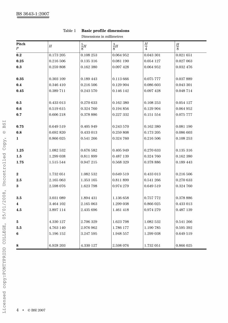
4.1 GeneralThis clause specifies the basic profile for ISO general purpose metric screw threads as shown in Figure 1. The dimensions for the various standard pitches are given in Table 1.
4.2 DimensionsThe fundamental deviations and tolerances specified in Clause 7 are applied to the dimensions of the basic profile shown in Figure 1 and derived from Table 1.
H 32
--------P 0.866i025i404P= =
58---H 0.541i265i877P=
38---H 0.324i759i526P=
H4---- 0.216i506i351P=
H8---- 0.108i253i175P=
Licensed copy:PONTYPRIDD COLLEGE, 05/01/2008, Uncontrolled Copy, © BSI

www.bzfxw.com
© B
SI 2007•
3
BS 3643-1:2007
Figure 1 Basic profile of ISO metric thread
90
(5/8
)H
P/8
P
P/2
P/4
30
60
Axis of screw thread
H/4
H/8
(3/8
)H
H
D dD1D2
d1
d2
Licensed copy:PONTYPRIDD COLLEGE, 05/01/2008, Uncontrolled Copy, © BSI
www.bzfxw.com
BS 3643-1:2007
4 • © BSI 2007
Table 1 Basic profile dimensionsDimensions in millimetres
PitchP
H
0.2 0.173 205 0.108 253 0.064 952 0.043 301 0.021 651
0.25 0.216 506 0.135 316 0.081 190 0.054 127 0.027 063
0.3 0.259 808 0.162 380 0.097 428 0.064 952 0.032 476
0.35 0.303 109 0.189 443 0.113 666 0.075 777 0.037 889
0.4 0.346 410 0.216 506 0.129 904 0.086 603 0.043 301
0.45 0.389 711 0.243 570 0.146 142 0.097 428 0.048 714
0.5 0.433 013 0.270 633 0.162 380 0.108 253 0.054 127
0.6 0.519 615 0.324 760 0.194 856 0.129 904 0.064 952
0.7 0.606 218 0.378 886 0.227 332 0.151 554 0.075 777
0.75 0.649 519 0.405 949 0.243 570 0.162 380 0.081 190
0.8 0.692 820 0.433 013 0.259 808 0.173 205 0.086 603
1 0.866 025 0.541 266 0.324 760 0.216 506 0.108 253
1.25 1.082 532 0.676 582 0.405 949 0.270 633 0.135 316
1.5 1.299 038 0.811 899 0.487 139 0.324 760 0.162 380
1.75 1.515 544 0.947 215 0.568 329 0.378 886 0.189 443
2 1.732 051 1.082 532 0.649 519 0.433 013 0.216 506
2.5 2.165 063 1.353 165 0.811 899 0.541 266 0.270 633
3 2.598 076 1.623 798 0.974 279 0.649 519 0.324 760
3.5 3.031 089 1.894 431 1.136 658 0.757 772 0.378 886
4 3.464 102 2.165 063 1.299 038 0.866 025 0.433 013
4.5 3.897 114 2.435 696 1.461 418 0.974 279 0.487 139
5 4.330 127 2.706 329 1.623 798 1.082 532 0.541 266
5.5 4.763 140 2.976 962 1.786 177 1.190 785 0.595 392
6 5.196 152 3.247 595 1.948 557 1.299 038 0.649 519
8 6.928 203 4.330 127 2.598 076 1.732 051 0.866 025
58---H 3
8---H
H4---- H
8----
Licensed copy:PONTYPRIDD COLLEGE, 05/01/2008, Uncontrolled Copy, © BSI
www.bzfxw.com
© BSI 2007 • 5
BS 3643-1:2007
5 General plan
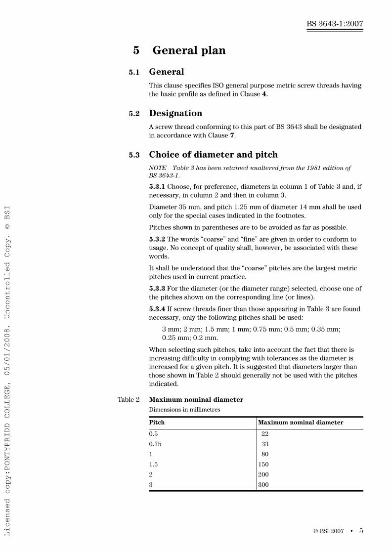
5.1 GeneralThis clause specifies ISO general purpose metric screw threads having the basic profile as defined in Clause 4.
5.2 DesignationA screw thread conforming to this part of BS 3643 shall be designated in accordance with Clause 7.
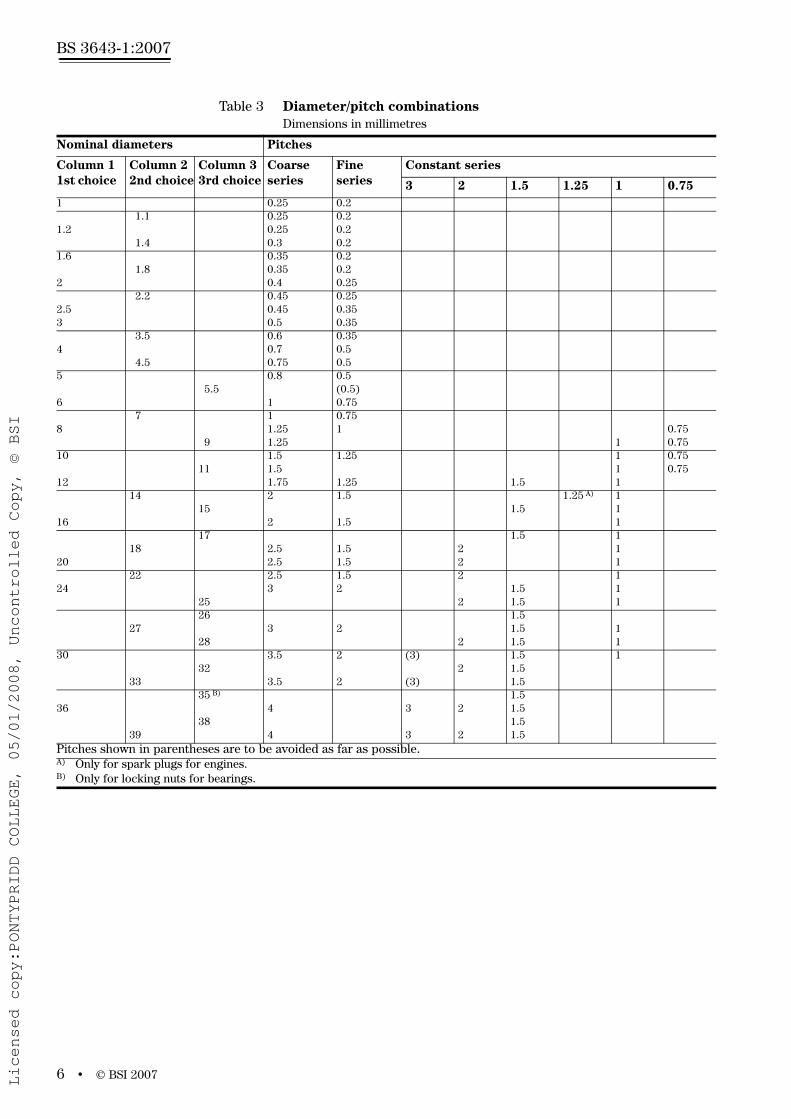
5.3 Choice of diameter and pitchNOTE Table 3 has been retained unaltered from the 1981 edition of BS 3643-1.
5.3.1 Choose, for preference, diameters in column 1 of Table 3 and, if necessary, in column 2 and then in column 3.
Diameter 35 mm, and pitch 1.25 mm of diameter 14 mm shall be used only for the special cases indicated in the footnotes.
Pitches shown in parentheses are to be avoided as far as possible.
5.3.2 The words “coarse” and “fine” are given in order to conform to usage. No concept of quality shall, however, be associated with these words.
It shall be understood that the “coarse” pitches are the largest metric pitches used in current practice.
5.3.3 For the diameter (or the diameter range) selected, choose one of the pitches shown on the corresponding line (or lines).
5.3.4 If screw threads finer than those appearing in Table 3 are found necessary, only the following pitches shall be used:
3 mm; 2 mm; 1.5 mm; 1 mm; 0.75 mm; 0.5 mm; 0.35 mm; 0.25 mm; 0.2 mm.
When selecting such pitches, take into account the fact that there is increasing difficulty in complying with tolerances as the diameter is increased for a given pitch. It is suggested that diameters larger than those shown in Table 2 should generally not be used with the pitches indicated.
Table 2 Maximum nominal diameterDimensions in millimetres
Pitch Maximum nominal diameter
0.5 22
0.75 33
1 80
1.5 150
2 200
3 300
Licensed copy:PONTYPRIDD COLLEGE, 05/01/2008, Uncontrolled Copy, © BSI
www.bzfxw.com
BS 3643-1:2007
6 • © BSI 2007
Table 3 Diameter/pitch combinationsDimensions in millimetres
Nominal diameters Pitches
Column 1 1st choice
Column 2 2nd choice
Column 3 3rd choice
Coarse series
Fine series
Constant series
3 2 1.5 1.25 1 0.751 0.25 0.2
1.1 0.25 0.2 1.2 0.25 0.2
1.4 0.3 0.21.6 0.35 0.2
1.8 0.35 0.2 2 0.4 0.25
2.2 0.45 0.25 2.5 0.45 0.353 0.5 0.35
3.5 0.6 0.35 4 0.7 0.5
4.5 0.75 0.55 0.8 0.5
5.5 (0.5) 6 1 0.75
7 1 0.75 8 1.25 1 0.75
9 1.25 1 0.7510 1.5 1.25 1 0.75
11 1.5 1 0.7512 1.75 1.25 1.5 1
14 2 1.5 1.25 A) 115 1.5 1
16 2 1.5 117 1.5 1
18 2.5 1.5 2 1 20 2.5 1.5 2 1
22 2.5 1.5 2 1 24 3 2 1.5 1
25 2 1.5 126 1.5
27 3 2 1.5 1 28 2 1.5 1
30 3.5 2 (3) 1.5 132 2 1.5
33 3.5 2 (3) 1.5 35 B) 1.5
36 4 3 2 1.538 1.5
39 4 3 2 1.5Pitches shown in parentheses are to be avoided as far as possible.A) Only for spark plugs for engines.B) Only for locking nuts for bearings.
Licensed copy:PONTYPRIDD COLLEGE, 05/01/2008, Uncontrolled Copy, © BSI

www.bzfxw.com
© BSI 2007 • 7
BS 3643-1:2007
Table 3 Diameter/pitch combinations (continued)Dimensions in millimetres
Nominal diameters Pitches
Column 11st choice
Column 22nd choice
Column 33rd choice
Coarse series
Constant series
6 4 3 2 1.540 3 2 1.5
42 4.5 4 3 2 1.5 45 4.5 4 3 2 1.5
48 5 4 3 2 1.5 50 3 2 1.5
52 5 4 3 2 1.555 4 3 2 1.5
56 5.5 4 3 2 1.5 58 4 3 2 1.5
60 5.5 4 3 2 1.5 62 4 3 2 1.5
64 6 4 3 2 1.565 4 3 2 1.5
68 6 4 3 2 1.5 70 6 4 3 2 1.5
72 6 4 3 2 1.5 75 4 3 2 1.5
76 6 4 3 2 1.578 2
80 6 4 3 2 1.582 2
85 6 4 3 2 90 6 4 3 2
95 6 4 3 2100 6 4 3 2
105 6 4 3 2 110 6 4 3 2
115 6 4 3 2 120 6 4 3 2
125 6 4 3 2130 6 4 3 2
135 6 4 3 2 140 6 4 3 2
145 6 4 3 2 150 6 4 3 2
155 6 4 3160 6 4 3
165 6 4 3 170 6 4 3
175 6 4 3 180 6 4 3
185 6 4 3190 6 4 3
195 6 4 3 200 6 4 3
205 6 4 3 210 6 4 3
215 6 4 3220 6 4 3
225 6 4 3 230 6 4 3 235 6 4 3
240 6 4 3 245 6 4 3
250 6 4 3255 6 4
260 6 4 265 6 4270 6 4275 6 4
280 6 4 285 6 4 290 6 4295 6 4
300 6 4
Licensed copy:PONTYPRIDD COLLEGE, 05/01/2008, Uncontrolled Copy, © BSI

www.bzfxw.com
BS 3643-1:2007
8 • © BSI 2007
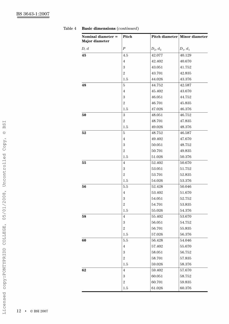
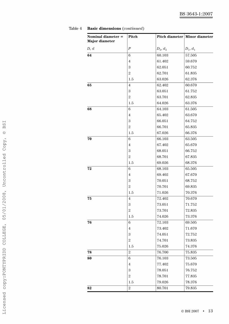
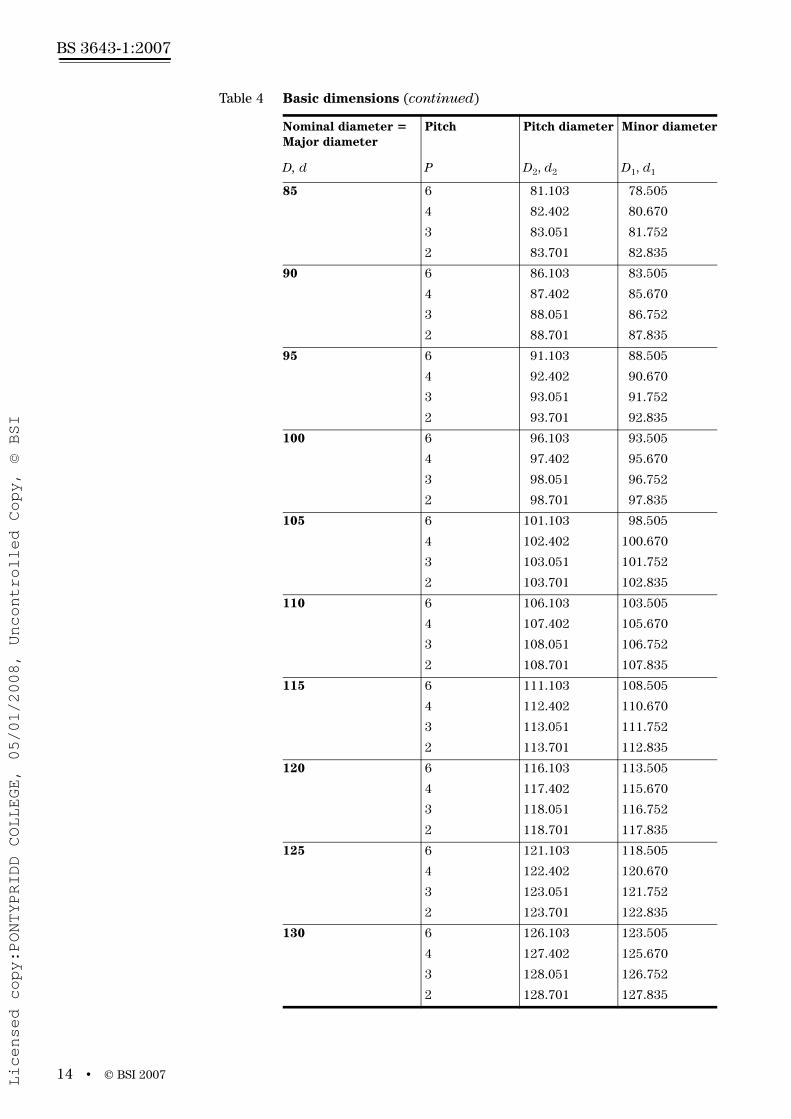
6 Basic dimensions
6.1 GeneralThis clause specifies the basic dimensions, in millimetres, of ISO metric screw threads in accordance with Clause 5.
The values refer to the basic profile in accordance with Clause 4.
6.2 Basic dimensionsThe basic dimensions shall be as shown in Figure 2 and given in Table 4.
The values of D2, d2, D1 and d1 have been calculated from the following formulae and rounded, in Table 4, to the third decimal place:
D2 = D – 2 × = D – 0.649 5P
d2 = d – 2 × = d – 0.649 5P
D1 = D – 2 × = D – 1.082 5P
d1 = d – 2 × = d – 1.082 5P
38
H
38
H
58
H
58
H
Figure 2 Basic dimensions
H
D,
D ,
1D , 2
P
d d1d2
Licensed copy:PONTYPRIDD COLLEGE, 05/01/2008, Uncontrolled Copy, © BSI

www.bzfxw.com
© BSI 2007 • 9
BS 3643-1:2007
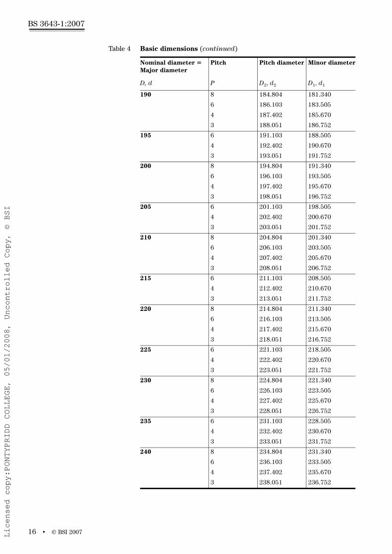
Table 4 Basic dimensions
Nominal diameter = Major diameter
Pitch Pitch diameter Minor diameter
D, d P D2, d2 D1, d1
1 0.25 0.838 0.729
0.2 0.870 0.783
1.1 0.25 0.938 0.829
0.2 0.970 0.883
1.2 0.25 1.038 0.929
0.2 1.070 0.983
1.4 0.3 1.205 1.075
0.2 1.270 1.183
1.6 0.35 1.373 1.221
0.2 1.470 1.383
1.8 0.35 1.573 1.421
0.2 1.670 1.583
2 0.4 1.740 1.567
0.25 1.838 1.729
2.2 0.45 1.908 1.713
0.25 2.038 1.929
2.5 0.45 2.208 2.013
0.35 2.273 2.121
3 0.5 2.675 2.459
0.35 2.773 2.621
3.5 0.6 3.110 2.850
0.35 3.273 3.121
4 0.7 3.545 3.242
0.5 3.675 3.459
4.5 0.75 4.013 3.688
0.5 4.175 3.959
5 0.8 4.480 4.134
0.5 4.675 4.459
5.5 0.5 5.175 4.959
6 1 5.350 4.917
0.75 5.513 5.188
7 1 6.350 5.917
0.75 6.513 6.188
8 1.25 7.188 6.647
1 7.350 6.917
0.75 7.513 7.188
9 1.25 8.188 7.647
1 8.350 7.917
0.75 8.513 8.188
Licensed copy:PONTYPRIDD COLLEGE, 05/01/2008, Uncontrolled Copy, © BSI

www.bzfxw.com
BS 3643-1:2007
10 • © BSI 2007
Table 4 Basic dimensions (continued)
Nominal diameter = Major diameter
Pitch Pitch diameter Minor diameter
D, d P D2, d2 D1, d1
10 1.5 9.026 8.376
1.25 9.188 8.647
1 9.350 8.917
0.75 9.513 9.188
11 1.5 10.026 9.376
1 10.350 9.917
0.75 10.513 10.188
12 1.75 10.863 10.106
1.5 11.026 10.376
1.25 11.188 10.647
1 11.350 10.917
14 2 12.701 11.835
1.5 13.026 12.376
1.25 13.188 12.647
1 13.350 12.917
15 1.5 14.026 13.376
1 14.350 13.917
16 2 14.701 13.835
1.5 15.026 14.376
1 15.350 14.917
17 1.5 16.026 15.376
1 16.350 15.917
18 2.5 16.376 15.294
2 16.701 15.835
1.5 17.026 16.376
1 17.350 16.917
20 2.5 18.376 17.294
2 18.701 17.835
1.5 19.026 18.376
1 19.350 18.917
22 2.5 20.376 19.294
2 20.701 19.835
1.5 21.026 20.376
1 21.350 20.917
24 3 22.051 20.752
2 22.701 21.835
1.5 23.026 22.376
1 23.350 22.917
25 2 23.701 22.835
1.5 24.026 23.376
1 24.350 23.917
Licensed copy:PONTYPRIDD COLLEGE, 05/01/2008, Uncontrolled Copy, © BSI

www.bzfxw.com
© BSI 2007 • 11
BS 3643-1:2007
26 1.5 25.026 24.376
27 3 25.051 23.752
2 25.701 24.835
1.5 26.026 25.376
1 26.350 25.917
28 2 26.701 25.835
1.5 27.026 26.376
1 27.350 26.917
30 3.5 27.727 26.211
3 28.051 26.752
2 28.701 27.835
1.5 29.026 28.376
1 29.350 28.917
32 2 30.701 29.835
1.5 31.026 30.376
33 3.5 30.727 29.211
3 31.051 29.752
2 31.701 30.835
1.5 32.026 31.376
35 1.5 34.026 33.376
36 4 33.402 31.670
3 34.051 32.752
2 34.701 33.835
1.5 35.026 34.376
38 1.5 37.026 36.376
39 4 36.402 34.670
3 37.051 35.752
2 37.701 36.835
1.5 38.026 37.376
40 3 38.051 36.752
2 38.701 37.835
1.5 39.026 38.376
42 4.5 39.077 37.129
4 39.402 37.670
3 40.051 38.752
2 40.701 39.835
1.5 41.026 40.376
Table 4 Basic dimensions (continued)
Nominal diameter = Major diameter
Pitch Pitch diameter Minor diameter
D, d P D2, d2 D1, d1
Licensed copy:PONTYPRIDD COLLEGE, 05/01/2008, Uncontrolled Copy, © BSI
www.bzfxw.com
BS 3643-1:2007
12 • © BSI 2007
45 4.5 42.077 40.129
4 42.402 40.670
3 43.051 41.752
2 43.701 42.835
1.5 44.026 43.376
48 5 44.752 42.587
4 45.402 43.670
3 46.051 44.752
2 46.701 45.835
1.5 47.026 46.376
50 3 48.051 46.752
2 48.701 47.835
1.5 49.026 48.376
52 5 48.752 46.587
4 49.402 47.670
3 50.051 48.752
2 50.701 49.835
1.5 51.026 50.376
55 4 52.402 50.670
3 53.051 51.752
2 53.701 52.835
1.5 54.026 53.376
56 5.5 52.428 50.046
4 53.402 51.670
3 54.051 52.752
2 54.701 53.835
1.5 55.026 54.376
58 4 55.402 53.670
3 56.051 54.752
2 56.701 55.835
1.5 57.026 56.376
60 5.5 56.428 54.046
4 57.402 55.670
3 58.051 56.752
2 58.701 57.835
1.5 59.026 58.376
62 4 59.402 57.670
3 60.051 58.752
2 60.701 59.835
1.5 61.026 60.376
Table 4 Basic dimensions (continued)
Nominal diameter = Major diameter
Pitch Pitch diameter Minor diameter
D, d P D2, d2 D1, d1
Licensed copy:PONTYPRIDD COLLEGE, 05/01/2008, Uncontrolled Copy, © BSI
www.bzfxw.com
© BSI 2007 • 13
BS 3643-1:2007
64 6 60.103 57.505
4 61.402 59.670
3 62.051 60.752
2 62.701 61.835
1.5 63.026 62.376
65 4 62.402 60.670
3 63.051 61.752
2 63.701 62.835
1.5 64.026 63.376
68 6 64.103 61.505
4 65.402 63.670
3 66.051 64.752
2 66.701 65.835
1.5 67.026 66.376
70 6 66.103 63.505
4 67.402 65.670
3 68.051 66.752
2 68.701 67.835
1.5 69.026 68.376
72 6 68.103 65.505
4 69.402 67.670
3 70.051 68.752
2 70.701 69.835
1.5 71.026 70.376
75 4 72.402 70.670
3 73.051 71.752
2 73.701 72.835
1.5 74.026 73.376
76 6 72.103 69.505
4 73.402 71.670
3 74.051 72.752
2 74.701 73.835
1.5 75.026 74.376
78 2 76.700 75.835
80 6 76.103 73.505
4 77.402 75.670
3 78.051 76.752
2 78.701 77.835
1.5 79.026 78.376
82 2 80.701 79.835
Table 4 Basic dimensions (continued)
Nominal diameter = Major diameter
Pitch Pitch diameter Minor diameter
D, d P D2, d2 D1, d1
Licensed copy:PONTYPRIDD COLLEGE, 05/01/2008, Uncontrolled Copy, © BSI
www.bzfxw.com
BS 3643-1:2007
14 • © BSI 2007
85 6 81.103 78.505
4 82.402 80.670
3 83.051 81.752
2 83.701 82.835
90 6 86.103 83.505
4 87.402 85.670
3 88.051 86.752
2 88.701 87.835
95 6 91.103 88.505
4 92.402 90.670
3 93.051 91.752
2 93.701 92.835
100 6 96.103 93.505
4 97.402 95.670
3 98.051 96.752
2 98.701 97.835
105 6 101.103 98.505
4 102.402 100.670
3 103.051 101.752
2 103.701 102.835
110 6 106.103 103.505
4 107.402 105.670
3 108.051 106.752
2 108.701 107.835
115 6 111.103 108.505
4 112.402 110.670
3 113.051 111.752
2 113.701 112.835
120 6 116.103 113.505
4 117.402 115.670
3 118.051 116.752
2 118.701 117.835
125 6 121.103 118.505
4 122.402 120.670
3 123.051 121.752
2 123.701 122.835
130 6 126.103 123.505
4 127.402 125.670
3 128.051 126.752
2 128.701 127.835
Table 4 Basic dimensions (continued)
Nominal diameter = Major diameter
Pitch Pitch diameter Minor diameter
D, d P D2, d2 D1, d1
Licensed copy:PONTYPRIDD COLLEGE, 05/01/2008, Uncontrolled Copy, © BSI

www.bzfxw.com
© BSI 2007 • 15
BS 3643-1:2007
135 6 131.103 128.505
4 132.402 130.670
3 133.051 131.752
2 133.701 132.835
140 6 136.103 133.505
4 137.402 135.670
3 138.051 136.752
2 138.701 137.835
145 6 141.103 138.505
4 142.402 140.670
3 143.051 141.752
2 143.701 142.835
150 8 144.804 141.340
6 146.103 143.505
4 147.402 145.670
3 148.051 146.752
2 148.701 147.835
155 6 151.103 148.505
4 152.402 150.670
3 153.051 151.752
160 8 154.804 151.340
6 156.103 153.505
4 157.402 155.670
3 158.051 156.752
165 6 161.103 158.505
4 162.402 160.670
3 163.051 161.752
170 8 164.804 161.340
6 166.103 163.505
4 167.402 165.670
3 168.051 166.752
175 6 171.103 168.505
4 172.402 170.670
3 173.051 171.752
180 8 174.804 171.340
6 176.103 173.505
4 177.402 175.670
3 178.051 176.752
185 6 181.103 178.505
4 182.402 180.670
3 183.051 181.752
Table 4 Basic dimensions (continued)
Nominal diameter = Major diameter
Pitch Pitch diameter Minor diameter
D, d P D2, d2 D1, d1
Licensed copy:PONTYPRIDD COLLEGE, 05/01/2008, Uncontrolled Copy, © BSI
www.bzfxw.com
BS 3643-1:2007
16 • © BSI 2007
190 8 184.804 181.340
6 186.103 183.505
4 187.402 185.670
3 188.051 186.752
195 6 191.103 188.505
4 192.402 190.670
3 193.051 191.752
200 8 194.804 191.340
6 196.103 193.505
4 197.402 195.670
3 198.051 196.752
205 6 201.103 198.505
4 202.402 200.670
3 203.051 201.752
210 8 204.804 201.340
6 206.103 203.505
4 207.402 205.670
3 208.051 206.752
215 6 211.103 208.505
4 212.402 210.670
3 213.051 211.752
220 8 214.804 211.340
6 216.103 213.505
4 217.402 215.670
3 218.051 216.752
225 6 221.103 218.505
4 222.402 220.670
3 223.051 221.752
230 8 224.804 221.340
6 226.103 223.505
4 227.402 225.670
3 228.051 226.752
235 6 231.103 228.505
4 232.402 230.670
3 233.051 231.752
240 8 234.804 231.340
6 236.103 233.505
4 237.402 235.670
3 238.051 236.752
Table 4 Basic dimensions (continued)
Nominal diameter = Major diameter
Pitch Pitch diameter Minor diameter
D, d P D2, d2 D1, d1
Licensed copy:PONTYPRIDD COLLEGE, 05/01/2008, Uncontrolled Copy, © BSI

www.bzfxw.com
© BSI 2007 • 17
BS 3643-1:2007
245 6 241.103 238.505
4 242.402 240.670
3 243.051 241.752
250 8 244.804 241.340
6 246.103 243.505
4 247.402 245.670
3 248.051 246.752
255 6 251.103 248.505
4 252.402 250.670
260 8 254.804 251.340
6 256.103 253.505
4 257.402 255.670
265 6 261.103 258.505
4 262.402 260.670
270 8 264.804 261.340
6 266.103 263.505
4 267.402 265.670
275 6 271.103 268.505
4 272.402 270.670
280 8 274.804 271.340
6 276.103 273.505
4 277.402 275.670
285 6 281.103 278.505
4 282.402 280.670
290 8 284.804 281.340
6 286.103 283.505
4 287.402 285.670
295 6 291.103 288.505
4 292.402 290.670
300 8 294.804 291.340
6 296.103 293.505
4 297.402 295.670
Table 4 Basic dimensions (continued)
Nominal diameter = Major diameter
Pitch Pitch diameter Minor diameter
D, d P D2, d2 D1, d1
Licensed copy:PONTYPRIDD COLLEGE, 05/01/2008, Uncontrolled Copy, © BSI

www.bzfxw.com
BS 3643-1:2007
18 • © BSI 2007
7 Tolerances – Principles and basic data
7.1 GeneralThis clause specifies a tolerance system for screw threads conforming to Clause 5. The tolerance system refers to the basic profile in accordance with Clause 4.
7.2 Structure of the tolerance systemThe system gives tolerances defined by tolerance grades and tolerance positions and a selection of grades and positions.
The system provides for the following.
a) A series of tolerance grades for each of the four screw thread diameters, as follows:
Details of tolerance grades and combinations of tolerance grades for pitch and crest diameters according to tolerance quality and length of engagement group required, with an order of preference, are given in 7.10.
b) A series of tolerance positions:
• G and H for internal threads;
• e, f, g and h for external threads.
The established tolerance positions are in accordance with the requirements of current coating thicknesses and with the demands of easy assembly. Tolerance positions with respect to the zero line (basic size) are shown in Figure 3.
c) A selection of recommended combinations of grades and positions (tolerance classes) giving the commonly used tolerance qualities fine, medium and coarse for the three groups of length of thread engagement short, normal and long. A further selection of tolerance classes is given for commercial bolt and nut threads. Tolerance classes other than those shown in 7.10 are not recommended and shall be used only for special cases.
Tolerance grades
D1 4, 5, 6, 7, 8
d 4, 6, 8
D2 4, 5, 6, 7, 8
d2 3, 4, 5, 6, 7, 8, 9
Licensed copy:PONTYPRIDD COLLEGE, 05/01/2008, Uncontrolled Copy, © BSI

www.bzfxw.com
© BSI 2007 • 19
BS 3643-1:2007
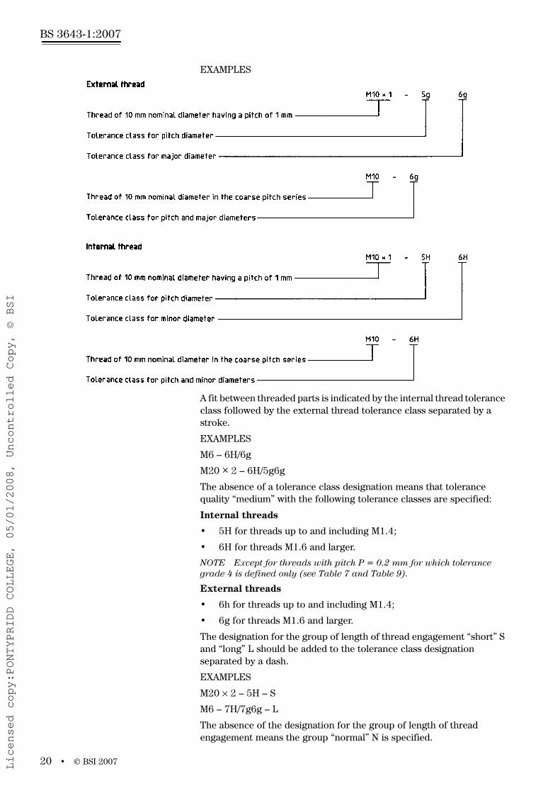
7.3 DesignationThe complete designation for a screw thread comprises a designation for the thread system and size, a designation for the thread tolerance class followed by further individual items if necessary.
A screw thread conforming to this part of BS 3643 shall be designated by the letter M followed by the value of the nominal diameter and of the pitch, expressed in millimetres and separated by the sign “×”.
EXAMPLE
M8 × 1.25
For coarse pitch threads listed in Table 2 and Table 3 the pitch may be omitted.
The tolerance class designation comprises a class designation for the pitch diameter tolerance followed by a class designation for the crest diameter tolerance.
Each class designation consists of:
• a figure indicating the tolerance grade;
• a letter indicating the tolerance position, capital (upper case) for internal threads, small (lower case) for external threads.
If the two class designations for the pitch diameter and crest diameter (major or minor diameter for internal and external threads respectively) are the same, it is not necessary to repeat the symbols.
Figure 3 Tolerance positions with respect to zero line (basic size)
ES
EIes
ei
0
TT
Licensed copy:PONTYPRIDD COLLEGE, 05/01/2008, Uncontrolled Copy, © BSI
www.bzfxw.com
BS 3643-1:2007
20 • © BSI 2007
EXAMPLES
A fit between threaded parts is indicated by the internal thread tolerance class followed by the external thread tolerance class separated by a stroke.
EXAMPLES
M6 – 6H/6g
M20 × 2 – 6H/5g6g
The absence of a tolerance class designation means that tolerance quality “medium” with the following tolerance classes are specified:
Internal threads
• 5H for threads up to and including M1.4;
• 6H for threads M1.6 and larger.
NOTE Except for threads with pitch P = 0.2 mm for which tolerance grade 4 is defined only (see Table 7 and Table 9).
External threads
• 6h for threads up to and including M1.4;
• 6g for threads M1.6 and larger.
The designation for the group of length of thread engagement “short” S and “long” L should be added to the tolerance class designation separated by a dash.
EXAMPLES
M20 × 2 – 5H – S
M6 – 7H/7g6g – L
The absence of the designation for the group of length of thread engagement means the group “normal” N is specified.
Licensed copy:PONTYPRIDD COLLEGE, 05/01/2008, Uncontrolled Copy, © BSI

www.bzfxw.com
© BSI 2007 • 21
BS 3643-1:2007
7.4 Tolerance gradesFor each of the two elements, pitch diameter and crest diameter, a number of tolerance grades have been established. In each case, grade 6 shall be used for tolerance quality medium and normal length of thread engagement. The grades below 6 are intended for tolerance quality fine and/or short lengths of thread engagement. The grades above 6 are intended for tolerance quality coarse and/or long lengths of thread engagement. In some grades, certain tolerance values for small pitches are not shown because of insufficient thread overlap or the requirement that the pitch diameter tolerance shall not exceed the crest diameter tolerance.
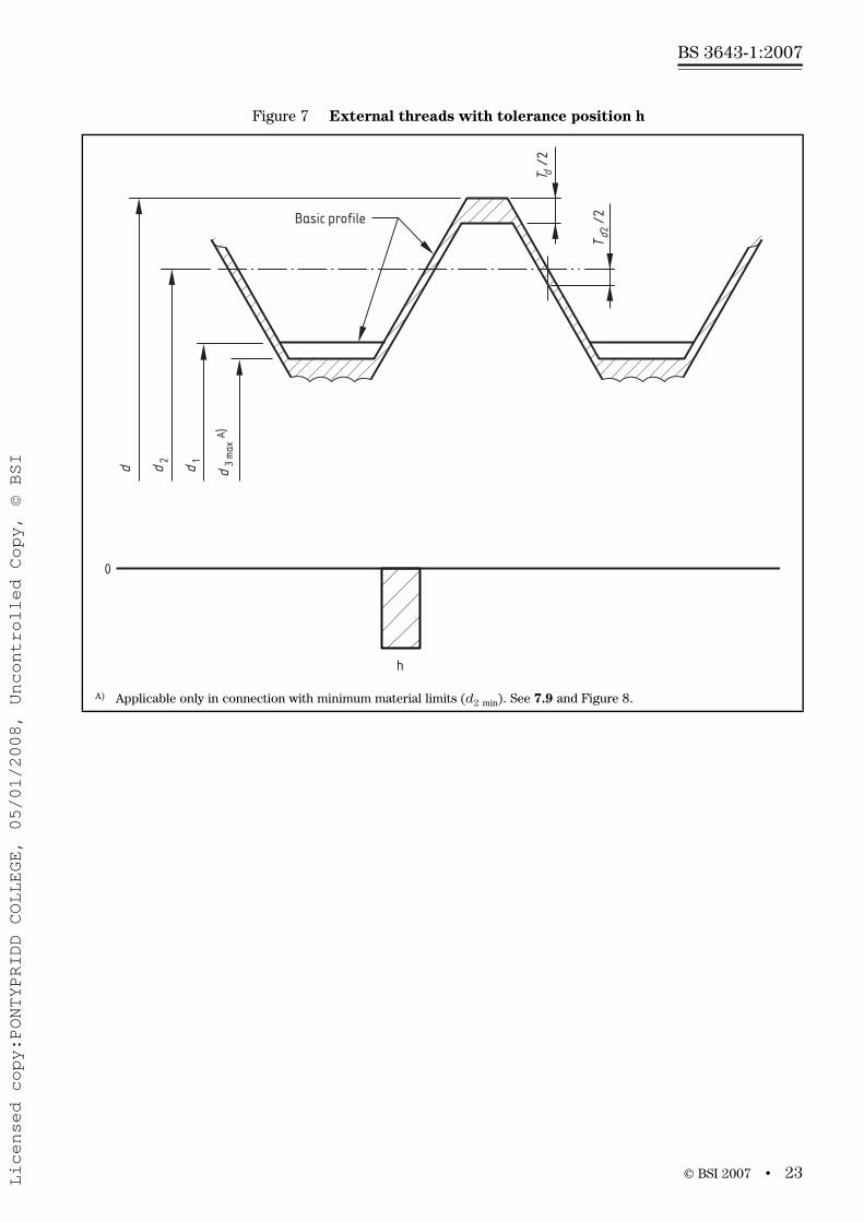
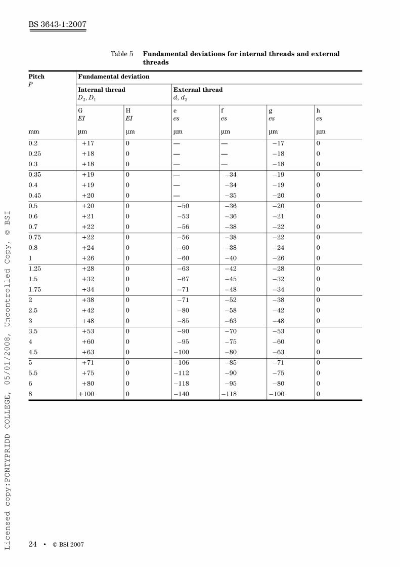
7.5 Tolerance positionsThe following tolerance positions are standardized:
• for internal threads: G with positive fundamental deviation
H with zero fundamental deviation
(See Figure 4 and Figure 5)
• for external threads: e, f and g with negative fundamental deviation
h with zero fundamental deviation
(See Figure 6 and Figure 7)
The values of the fundamental deviations are given in Table 5.
Figure 4 Internal threads with tolerance position G
0
GD1
D D2
EI/2
Basic profile
T
/2
D2
T
/2
D1
Licensed copy:PONTYPRIDD COLLEGE, 05/01/2008, Uncontrolled Copy, © BSI

www.bzfxw.com
BS 3643-1:2007
22 • © BSI 2007
Figure 5 Internal threads with tolerance position H
Figure 6 External threads with tolerance positions e, f and g
A) Applicable only in connection with minimum material limits (d2 min). See 7.9 and Figure 8.
0
H
D1
D D2
Basic profile
T
/2
D2
T
/2
D1
0
gf
e
Basic profile
d3
max
d1
d d2
A)
es/2
T
/2
d2
T /
2d
Licensed copy:PONTYPRIDD COLLEGE, 05/01/2008, Uncontrolled Copy, © BSI
www.bzfxw.com
© BSI 2007 • 23
BS 3643-1:2007
Figure 7 External threads with tolerance position h
A) Applicable only in connection with minimum material limits (d2 min). See 7.9 and Figure 8.
d3
max
d1
Basic profileA)
d d2
0
h
T /
2d
T
/2
d2
Licensed copy:PONTYPRIDD COLLEGE, 05/01/2008, Uncontrolled Copy, © BSI
www.bzfxw.com
BS 3643-1:2007
24 • © BSI 2007
Table 5 Fundamental deviations for internal threads and external threads
PitchP
Fundamental deviation
Internal threadD2, D1
External threadd, d2
GEI
HEI
ees
fes
ges
hes
mm μm μm μm μm μm μm
0.2 +17 0 — — p17 0
0.25 +18 0 — — p18 0
0.3 +18 0 — — p18 0
0.35 +19 0 — p34 p19 0
0.4 +19 0 — p34 p19 0
0.45 +20 0 — p35 p20 0
0.5 +20 0 p50 p36 p20 0
0.6 +21 0 p53 p36 p21 0
0.7 +22 0 p56 p38 p22 0
0.75 +22 0 p56 p38 p22 0
0.8 +24 0 p60 p38 p24 0
1 +26 0 p60 p40 p26 0
1.25 +28 0 p63 p42 p28 0
1.5 +32 0 p67 p45 p32 0
1.75 +34 0 p71 p48 p34 0
2 +38 0 p71 p52 p38 0
2.5 +42 0 p80 p58 p42 0
3 +48 0 p85 p63 p48 0
3.5 +53 0 p90 p70 p53 0
4 +60 0 p95 p75 p60 0
4.5 +63 0 p100 p80 p63 0
5 +71 0 p106 p85 p71 0
5.5 +75 0 p112 p90 p75 0
6 +80 0 p118 p95 p80 0
8 +100 0 p140 p118 p100 0
Licensed copy:PONTYPRIDD COLLEGE, 05/01/2008, Uncontrolled Copy, © BSI

www.bzfxw.com
© BSI 2007 • 25
BS 3643-1:2007
7.6 Lengths of thread engagementThe length of thread engagement is classified into one of three groups, S (short), N (normal) or L (long), in accordance with Table 6.
Table 6 Lengths of thread engagementDimensions in millimetres
Basic major diameterD, d
PitchP
Lengths of thread engagement
Short Normal Long
over up to and including
up to and including
over up to and including
over
0.99 1.4 0.2 0.5 0.5 1.4 1.4 0.25 0.6 0.6 1.7 1.7 0.3 0.7 0.7 2 2
1.4 2.8 0.2 0.5 0.5 1.5 1.5 0.25 0.6 0.6 1.9 1.9 0.35 0.8 0.8 2.6 2.6 0.4 1 1 3 3 0.45 1.3 1.3 3.8 3.8
2.8 5.6 0.35 1 1 3 3 0.5 1.5 1.5 4.5 4.5 0.6 1.7 1.7 5 5 0.7 2 2 6 6 0.75 2.2 2.2 6.7 6.7 0.8 2.5 2.5 7.5 7.5
5.6 11.2 0.75 2.4 2.4 7.1 7.1 1 3 3 9 9 1.25 4 4 12 12 1.5 5 5 15 15
11.2 22.4 1 3.8 3.8 11 11 1.25 4.5 4.5 13 13 1.5 5.6 5.6 16 16 1.75 6 6 18 18 2 8 8 24 24 2.5 10 10 30 30
22.4 45 1 4 4 12 12 1.5 6.3 6.3 19 19 2 8.5 8.5 25 25 3 12 12 36 36 3.5 15 15 45 45 4 18 18 53 53 4.5 21 21 63 63
45 90 1.5 7.5 7.5 22 22 2 9.5 9.5 28 28 3 15 15 45 45 4 19 19 56 56 5 24 24 71 71 5.5 28 28 85 85 6 32 32 95 95
90 180 2 12 12 36 36 3 18 18 53 53 4 24 24 71 71 6 36 36 106 1068 45 45 132 132
180 355 3 20 20 60 60 4 26 26 80 80 6 40 40 118 1188 50 50 150 150
Licensed copy:PONTYPRIDD COLLEGE, 05/01/2008, Uncontrolled Copy, © BSI

www.bzfxw.com
BS 3643-1:2007
26 • © BSI 2007
7.7 Crest diameter tolerances
7.7.1 Minor diameter tolerances of internal threads (TD1)
For the minor diameter tolerances of internal threads, TD1, there are five tolerance grades, 4, 5, 6, 7 and 8, in accordance with Table 7.
Table 7 Minor diameter tolerances of internal threads (TD1)
PitchP
Tolerance grade
4 5 6 7 8
mm μm μm μm μm μm
0.2 38 — — — —
0.25 45 56 — — —
0.3 53 67 85 — —
0.35 63 80 100 — —
0.4 71 90 112 — —
0.45 80 100 125 — —
0.5 90 112 140 180 —
0.6 100 125 160 200 —
0.7 112 140 180 224 —
0.75 118 150 190 236 —
0.8 125 160 200 250 315
1 150 190 236 300 375
1.25 170 212 265 335 425
1.5 190 236 300 375 475
1.75 212 265 335 425 530
2 236 300 375 475 600
2.5 280 355 450 560 710
3 315 400 500 630 800
3.5 355 450 560 710 900
4 375 475 600 750 950
4.5 425 530 670 850 1 060
5 450 560 710 900 1 120
5.5 475 600 750 950 1 180
6 500 630 800 1 000 1 250
8 630 800 1 000 1 250 1 600
Licensed copy:PONTYPRIDD COLLEGE, 05/01/2008, Uncontrolled Copy, © BSI

www.bzfxw.com
© BSI 2007 • 27
BS 3643-1:2007
7.7.2 Major diameter tolerances of external threads (Td)
For the major diameter tolerances of external threads, Td, there are three tolerance grades, 4, 6 and 8, in accordance with Table 8.
The tolerance grades 5 and 7 do not exist for the major diameter of external threads.
7.8 Pitch diameter tolerancesFor the pitch diameter tolerances of internal threads, TD2, there are five tolerance grades, 4, 5, 6, 7 and 8, in accordance with Table 9.
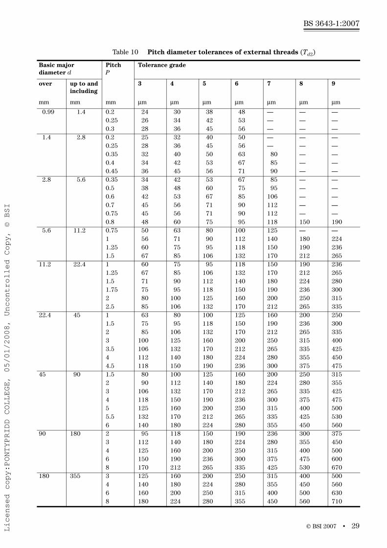
For the pitch diameter tolerances of external threads, Td2, there are seven tolerance grades, 3, 4, 5, 6, 7, 8 and 9, in accordance with Table 10.
Table 8 Major diameter tolerances of external threads (Td)
PitchP
Tolerance grade
4 6 8
mm μm μm μm
0.2 36 56 —
0.25 42 67 —
0.3 48 75 —
0.35 53 85 —
0.4 60 95 —
0.45 63 100 —
0.5 67 106 —
0.6 80 125 —
0.7 90 140 —
0.75 90 140 —
0.8 95 150 236
1 112 180 280
1.25 132 212 335
1.5 150 236 375
1.75 170 265 425
2 180 280 450
2.5 212 335 530
3 236 375 600
3.5 265 425 670
4 300 475 750
4.5 315 500 800
5 335 530 850
5.5 355 560 900
6 375 600 950
8 450 710 1 180
Licensed copy:PONTYPRIDD COLLEGE, 05/01/2008, Uncontrolled Copy, © BSI

www.bzfxw.com
BS 3643-1:2007
28 • © BSI 2007
Table 9 Pitch diameter tolerances of internal threads (TD2)
Basic major diameterD
PitchP
Tolerance grade
over up to and including
4 5 6 7 8
mm mm mm μm μm μm μm μm
0.99 1.4 0.2 40 — — — — 0.25 45 56 — — — 0.3 48 60 75 — —
1.4 2.8 0.2 42 — — — — 0.25 48 60 — — — 0.35 53 67 85 — — 0.4 56 71 90 — — 0.45 60 75 95 — —
2.8 5.6 0.35 56 71 90 — — 0.5 63 80 100 125 — 0.6 71 90 112 140 — 0.7 75 95 118 150 — 0.75 75 95 118 150 — 0.8 80 100 125 160 200
5.6 11.2 0.75 85 106 132 170 — 1 95 118 150 190 236 1.25 100 125 160 200 250 1.5 112 140 180 224 280
11.2 22.4 1 100 125 160 200 250 1.25 112 140 180 224 280 1.5 118 150 190 236 300 1.75 125 160 200 250 315 2 132 170 212 265 335 2.5 140 180 224 280 355
22.4 45 1 106 132 170 212 — 1.5 125 160 200 250 315 2 140 180 224 280 355 3 170 212 265 335 425 3.5 180 224 280 355 450 4 190 236 300 375 475 4.5 200 250 315 400 500
45 90 1.5 132 170 212 265 335 2 150 190 236 300 375 3 180 224 280 355 450 4 200 250 315 400 500 5 212 265 335 425 530 5.5 224 280 355 450 560 6 236 300 375 475 600
90 180 2 160 200 250 315 400 3 190 236 300 375 475 4 212 265 335 425 530 6 250 315 400 500 6308 280 355 450 560 710
180 355 3 212 265 335 425 530 4 236 300 375 475 600 6 265 335 425 530 6708 300 375 475 600 750
Licensed copy:PONTYPRIDD COLLEGE, 05/01/2008, Uncontrolled Copy, © BSI
www.bzfxw.com
© BSI 2007 • 29
BS 3643-1:2007
Table 10 Pitch diameter tolerances of external threads (Td2)
Basic major diameter d
PitchP
Tolerance grade
over up to and including
3 4 5 6 7 8 9
mm mm mm μm μm μm μm μm μm μm
0.99 1.4 0.2 24 30 38 48 — — — 0.25 26 34 42 53 — — — 0.3 28 36 45 56 — — —
1.4 2.8 0.2 25 32 40 50 — — — 0.25 28 36 45 56 — — — 0.35 32 40 50 63 80 — — 0.4 34 42 53 67 85 — — 0.45 36 45 56 71 90 — —
2.8 5.6 0.35 34 42 53 67 85 — —0.5 38 48 60 75 95 — —0.6 42 53 67 85 106 — —0.7 45 56 71 90 112 — —0.75 45 56 71 90 112 — —0.8 48 60 75 95 118 150 190
5.6 11.2 0.75 50 63 80 100 125 — — 1 56 71 90 112 140 180 224 1.25 60 75 95 118 150 190 236 1.5 67 85 106 132 170 212 265
11.2 22.4 1 60 75 95 118 150 190 236 1.25 67 85 106 132 170 212 265 1.5 71 90 112 140 180 224 280 1.75 75 95 118 150 190 236 300 2 80 100 125 160 200 250 315 2.5 85 106 132 170 212 265 335
22.4 45 1 63 80 100 125 160 200 250 1.5 75 95 118 150 190 236 300 2 85 106 132 170 212 265 335 3 100 125 160 200 250 315 400 3.5 106 132 170 212 265 335 425 4 112 140 180 224 280 355 450 4.5 118 150 190 236 300 375 475
45 90 1.5 80 100 125 160 200 250 315 2 90 112 140 180 224 280 355 3 106 132 170 212 265 335 425 4 118 150 190 236 300 375 475 5 125 160 200 250 315 400 500 5.5 132 170 212 265 335 425 530 6 140 180 224 280 355 450 560
90 180 2 95 118 150 190 236 300 375 3 112 140 180 224 280 355 450 4 125 160 200 250 315 400 500 6 150 190 236 300 375 475 6008 170 212 265 335 425 530 670
180 355 3 125 160 200 250 315 400 500 4 140 180 224 280 355 450 560 6 160 200 250 315 400 500 6308 180 224 280 355 450 560 710
Licensed copy:PONTYPRIDD COLLEGE, 05/01/2008, Uncontrolled Copy, © BSI

www.bzfxw.com
BS 3643-1:2007
30 • © BSI 2007
7.9 Root contoursFor internal threads as well as for external threads, the actual root contours shall not at any point transgress the basic profile.
For external threads on fasteners of property class 8.8 and higher (see BS EN ISO 898-1), the root profile shall have a non-reversing curvature, no portion of which shall have a radius of less than 0.125 × P (see Figure 8 and Table 11).
In the maximum minor diameter position, d3, the two radii of Rmin = 0.125 × P will go through the points of intersection between the maximum material flanks and the minor diameter cylinder of the GO gauges in accordance with BS 919-3 and blend tangentially into the minimum material flanks.
The maximum truncation, Cmax, is calculated according to the following formula:
It is, however, advisable to attempt to obtain a truncation
of (R = 0.144 34 × P) and to take as the basis for stress
calculation of the minor diameter, d3, of external threads (for
corresponding values see Clause 8).
The minimum truncation, Cmin, is calculated according to the following formula:
External threads on fasteners of property classes below 8.8 should preferably conform to the requirements stated above. This is particularly important for fasteners or other screwed connections that are subjected to fatigue or impact. However, there are, in principle, no restrictions other than that the maximum minor diameter, d3 max, of the external thread shall be less than the minimum minor diameter of the GO gauges in accordance with BS 919-3.
2 2max min
min
π1 cos arc cos 1
4 3 4 2d dT TH
C RR
⎧ ⎫⎡ ⎤⎛ ⎞⎪ ⎪= − − − − +⎢ ⎥⎨ ⎬⎜ ⎟×⎢ ⎥⎝ ⎠⎪ ⎪⎣ ⎦⎩ ⎭
6H
6H
min 0.1257H
C P= ≈
Licensed copy:PONTYPRIDD COLLEGE, 05/01/2008, Uncontrolled Copy, © BSI

www.bzfxw.com
© BSI 2007 • 31
BS 3643-1:2007
Figure 8 External root profile
a) Position h b) Positions e, f and g
d3
min
Basic profile Go-gaugeprofile
d3
max
Cm
inCm
ax
Cm
in
Basic profile
Go-gauge profile
Cm
ax
d3
min
d3
max
R minR min
es/2
T
/2
d2 es/2
T
/2
d2
R min R
min
Table 11 Minimum root radii
PitchP
Rmin
mm μm
0.2 250.25 310.3 380.35 440.4 500.45 560.5 630.6 750.7 880.75 940.8 1001 1251.25 1561.5 1881.75 2192 2502.5 3133 3753.5 4384 5004.5 5635 6255.5 6886 7508 1 000
Licensed copy:PONTYPRIDD COLLEGE, 05/01/2008, Uncontrolled Copy, © BSI

www.bzfxw.com
BS 3643-1:2007
32 • © BSI 2007
7.10 Recommended tolerance classesIn order to reduce the numbers of gauges and tools the tolerance classes should preferably be chosen from Table 12 and Table 13.
The following general rules can be formulated for the choice of tolerance quality:
• fine: for precision threads, when little variation of fit character is needed;
• medium: for general use;
• coarse: for cases where manufacturing difficulties can arise, for example when threading hot-rolled bars and long blind holes.
If the actual length of thread engagement is unknown (as in the manufacturing of standard bolts), group N is recommended.
Tolerance classes in boxes with heavy outlines are selected for commercial external and internal threads.
Tolerance classes in bold type are first choice.
Tolerance classes in ordinary type are second choice.
Tolerance classes in parentheses are third choice.
Any of the recommended tolerance classes for internal threads can be combined with any of the recommended tolerance classes for external threads. However, in order to guarantee a sufficient overlap, the finished components should preferably be made to form the fits H/g, H/h or G/h. For thread sizes M1.4 and smaller the combinations 5H/6h, 4H/6h or finer shall be chosen.
For coated threads, the tolerances apply to the parts before coating, unless otherwise stated. After coating, the actual thread profile shall not at any point transgress the maximum material limits for positions H or h.
NOTE These provisions are intended for thin coatings, e.g. those obtained by electroplating.
Table 12 Recommended tolerance classes for internal threads
Tolerance quality
Tolerance position G Tolerance position H
S N L S N L
Fine — — — 4H 5H 6H
Medium (5G) 6G (7G) 5H 6H 7H
Coarse — (7G) (8G) — 7H 8H
Table 13 Recommended tolerance classes for external threads
Tolerance quality
Tolerance position e Tolerance position f Tolerance position g Tolerance position h
S N L S N L S N L S N L
Fine — — — — — — — (4g) (5g4g) (3h4h) 4h (5h4h)
Medium — 6e (7e6e) — 6f — (5g6g) 6g (7g6g) (5h6h) 6h (7h6h)
Coarse — (8e) (9e8e) — — — — 8g (9g8g) — — —
Licensed copy:PONTYPRIDD COLLEGE, 05/01/2008, Uncontrolled Copy, © BSI
www.bzfxw.com
© BSI 2007 • 33
BS 3643-1:2007
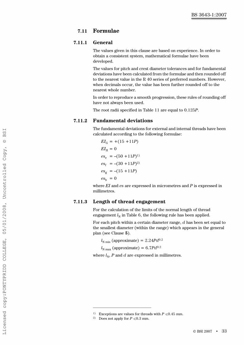
7.11 Formulae
7.11.1 General
The values given in this clause are based on experience. In order to obtain a consistent system, mathematical formulae have been developed.
The values for pitch and crest diameter tolerances and for fundamental deviations have been calculated from the formulae and then rounded off to the nearest value in the R 40 series of preferred numbers. However, when decimals occur, the value has been further rounded off to the nearest whole number.
In order to reproduce a smooth progression, these rules of rounding off have not always been used.
The root radii specified in Table 11 are equal to 0.125P.
7.11.2 Fundamental deviations
The fundamental deviations for external and internal threads have been calculated according to the following formulae:
EIG = +(15 +11P)
EIH = 0
ese = –(50 +11P)1)
esf = –(30 +11P)2)
esg = –(15 +11P)
esh = 0
where EI and es are expressed in micrometres and P is expressed in millimetres.
7.11.3 Length of thread engagement
For the calculation of the limits of the normal length of thread engagement lN in Table 6, the following rule has been applied.
For each pitch within a certain diameter range, d has been set equal to the smallest diameter (within the range) which appears in the general plan (see Clause 5).
lN min (approximate) = 2.24Pd0.2
lN max (approximate) = 6.7Pd0.2
where lN, P and d are expressed in millimetres.
1) Exceptions are values for threads with P u0.45 mm. 2) Does not apply for P u0.3 mm.
Licensed copy:PONTYPRIDD COLLEGE, 05/01/2008, Uncontrolled Copy, © BSI

www.bzfxw.com
BS 3643-1:2007
34 • © BSI 2007
7.11.4 Crest diameter tolerances
7.11.4.1 Tolerances for major diameter of external threads (Td), grade 6These tolerances have been calculated according to the following formula:
where Td is expressed in micrometres and P is expressed in millimetres.
Td-tolerances for the other grades are obtained from the Td(6)-values (see Table 8) according to the table below.
7.11.4.2 Tolerances for minor diameter of internal threads (TD1), grade 6TD1-tolerances for grade 6 are calculated according to the following formulae:
a) Pitches 0.2 mm to 0.8 mm:
TD1(6) = 433P – 190P1.22
b) Pitch 1 mm and coarser:
TD1(6) = 230P0.7
where TD1 is expressed in micrometres and P is expressed in millimetres.
The values for the other grades are obtained from the TD1(6)-values (in Table 7) according to the table below.
7.11.5 Pitch diameter tolerances
7.11.5.1 Tolerances for pitch diameter of external threads (Td2) Td2(6)-values in Table 10 are calculated according to the following formula (d being equal to the geometrical mean value of the diameter range limits):
Td2(6) = 90P0.4d0.1
where Td2(6) is expressed in micrometres and P and d are expressed in millimetres.
The values for the other grades are obtained from the Td2(6)-values (see Table 10) according to the table below.
No Td2-values are given in Table 10 when values calculated according to the given formulae exceed the Td-values in the tolerance grades which are combined in the tables for recommended tolerance classes.
( ) 3 2 3.156 180dT P
P= −
Tolerance grade
4 6 8
0.63Td(6) Td(6) 1.6Td(6)
Tolerance grade
4 5 6 7 8
0.63TD1(6) 0.8TD1(6) TD1(6) 1.25TD1(6) 1.6TD1(6)
Tolerance grade
3 4 5 6 7 8 9
0.5Td2(6) 0.63Td2(6) 0.8Td2(6) Td2(6) 1.25Td2(6) 1.6Td2(6) 2Td2(6)
Licensed copy:PONTYPRIDD COLLEGE, 05/01/2008, Uncontrolled Copy, © BSI

www.bzfxw.com
© BSI 2007 • 35
BS 3643-1:2007
7.11.5.2 Tolerances for pitch diameter of internal thread (TD2)
TD2-values are obtained from the Td2(6)-values (see Table 10) according to the table below.
No TD2-values are given in the Table 9 when values calculated according to the given formulae exceed 0.25P.
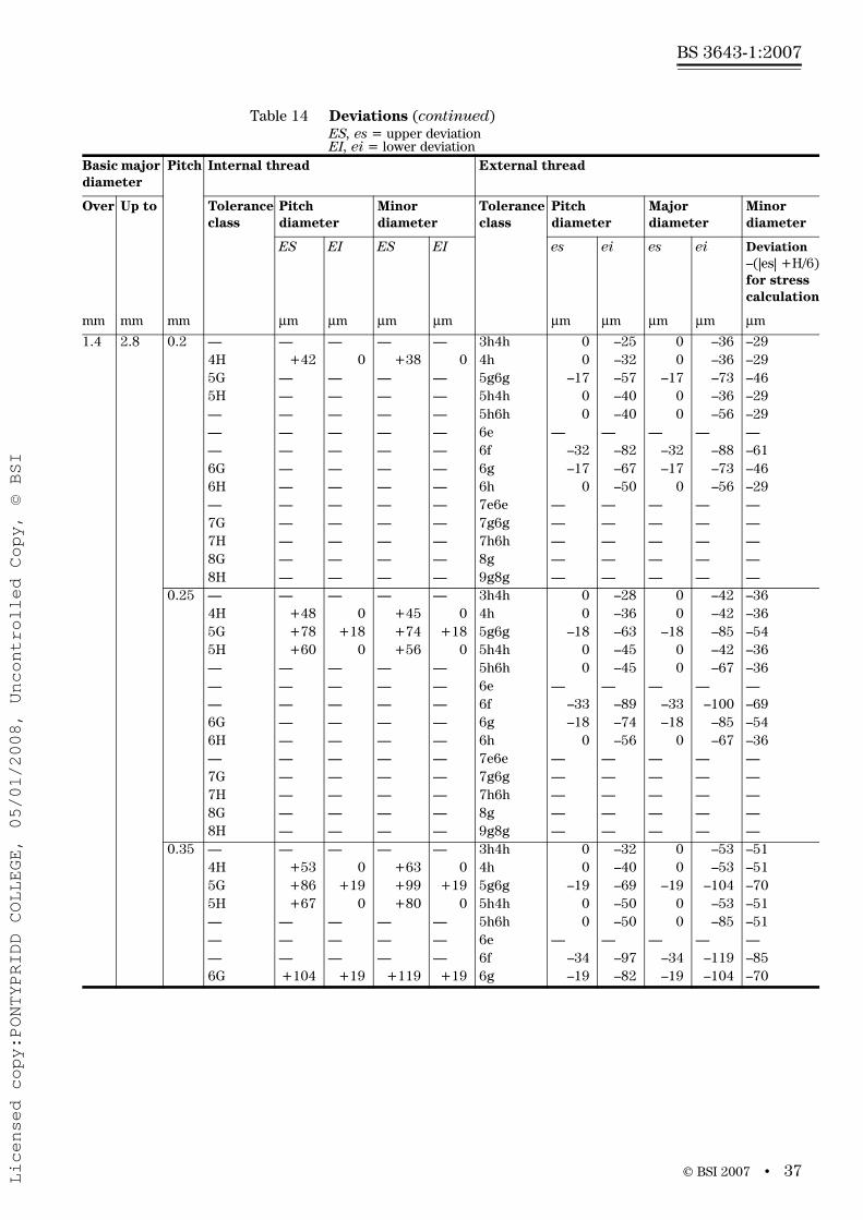
8 Tolerances – Deviations for constructional threads
8.1 GeneralThis clause specifies deviations for pitch and crest diameters for ISO general purpose metric screw threads conforming to Clause 5 having a basic profile in accordance with Clause 4.
The deviations specified are derived from the fundamental deviations and tolerances specified in Clause 7.
The values for the deviations are given in Table 14.
8.2 DeviationsFor internal threads as well as external threads, the actual root contour shall not in any point transgress the basic profile.
The tabulated deviation values for the minor diameter of the external
thread are calculated on the basis of an truncation and may be
used for stress calculations .
For coated threads, the tolerances apply to the parts before coating, unless otherwise stated. After coating, the actual thread profile shall not at any point transgress the maximum material limits for position H or h respectively.
NOTE These provisions are intended for thin coatings, for example those obtained by electroplating.
Tolerance grade
4 5 6 7 8
0.85Td2(6) 1.06Td2(6) 1.32Td2(6) 1.7Td2(6) 2.12Td2(6)
6H
deviation = es6H⎡ ⎤⎛ ⎞− +⎜ ⎟⎢ ⎥⎝ ⎠⎣ ⎦
Licensed copy:PONTYPRIDD COLLEGE, 05/01/2008, Uncontrolled Copy, © BSI

www.bzfxw.com
BS 3643-1:2007
36 • © BSI 2007
Table 14 DeviationsES, es = upper deviationEI, ei = lower deviation
Basic major diameter
Pitch Internal thread External thread
Over Up to Tolerance class
Pitch diameter
Minor diameter
Tolerance class
Pitch diameter
Major diameter
Minor diameter
ES EI ES EI es ei es ei Deviation–(|es| +H/6)for stress calculation
mm mm mm μm μm μm μm μm μm μm μm μm
0.99 1.4 0.2 — — — — — 3h4h 0 –24 0 –36 –294H +40 0 +38 0 4h 0 –30 0 –36 –295G — — — — 5g6g –17 –55 –17 –73 –465H — — — — 5h4h 0 –38 0 –36 –29— — — — — 5h6h 0 –38 0 –56 –29— — — — — 6e — — — — —— — — — — 6f — — — — —6G — — — — 6g –17 –65 –17 –73 –466H — — — — 6h 0 –48 0 –56 –29— — — — — 7e6e — — — — —7G — — — — 7g6g — — — — —7H — — — — 7h6h — — — — —8G — — — — 8g — — — — —8H — — — — 9g8g — — — — —
0.25 — — — — — 3h4h 0 – 26 0 –42 –364H +45 0 +45 0 4h 0 –34 0 –42 –365G +74 +18 +74 +18 5g6g –18 –60 –18 –85 –545H +56 0 +56 0 5h4h 0 –42 0 –42 –36— — — — — 5h6h 0 –42 0 –67 –36— — — — — 6e — — — — —— — — — — 6f — — — — —6G — — — — 6g –18 –71 –18 –85 –546H — — — — 6h 0 –53 0 –67 –36— — — — — 7e6e — — — — —7G — — — — 7g6g — — — — —7H — — — — 7h6h — — — — —8G — — — — 8g — — — — —8H — — — — 9g8g — — — — —
0.3 — — — — — 3h4h 0 –28 0 –48 –434H +48 0 +53 0 4h 0 –36 0 –48 –435G +78 +18 +85 +18 5g6g –18 –63 –18 –93 –615H +60 0 +67 0 5h4h 0 –45 0 –48 –43— — — — — 5h6h 0 –45 0 –75 –43— — — — — 6e — — — — —— — — — — 6f — — — — —6G +93 +18 +103 +18 6g –18 –74 –18 –93 –616H +75 0 +85 0 6h 0 –56 0 –75 –43— — — — — 7e6e — — — — —7G — — — — 7g6g — — — — —7H — — — — 7h6h — — — — —8G — — — — 8g — — — — —8H — — — — 9g8g — — — — —
Licensed copy:PONTYPRIDD COLLEGE, 05/01/2008, Uncontrolled Copy, © BSI
www.bzfxw.com
© BSI 2007 • 37
BS 3643-1:2007
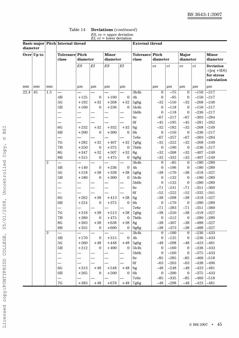
Table 14 Deviations (continued)ES, es = upper deviationEI, ei = lower deviation
Basic major diameter
Pitch Internal thread External thread
Over Up to Tolerance class
Pitch diameter
Minor diameter
Tolerance class
Pitch diameter
Major diameter
Minor diameter
ES EI ES EI es ei es ei Deviation–(|es| +H/6)for stress calculation
mm mm mm μm μm μm μm μm μm μm μm μm
1.4 2.8 0.2 — — — — — 3h4h 0 –25 0 –36 –294H +42 0 +38 0 4h 0 –32 0 –36 –295G — — — — 5g6g –17 –57 –17 –73 –465H — — — — 5h4h 0 –40 0 –36 –29— — — — — 5h6h 0 –40 0 –56 –29— — — — — 6e — — — — —— — — — — 6f –32 –82 –32 –88 –616G — — — — 6g –17 –67 –17 –73 –466H — — — — 6h 0 –50 0 –56 –29— — — — — 7e6e — — — — —7G — — — — 7g6g — — — — —7H — — — — 7h6h — — — — —8G — — — — 8g — — — — —8H — — — — 9g8g — — — — —
0.25 — — — — — 3h4h 0 –28 0 –42 –364H +48 0 +45 0 4h 0 –36 0 –42 –365G +78 +18 +74 +18 5g6g –18 –63 –18 –85 –545H +60 0 +56 0 5h4h 0 –45 0 –42 –36— — — — — 5h6h 0 –45 0 –67 –36— — — — — 6e — — — — —— — — — — 6f –33 –89 –33 –100 –696G — — — — 6g –18 –74 –18 –85 –546H — — — — 6h 0 –56 0 –67 –36— — — — — 7e6e — — — — —7G — — — — 7g6g — — — — —7H — — — — 7h6h — — — — —8G — — — — 8g — — — — —8H — — — — 9g8g — — — — —
0.35 — — — — — 3h4h 0 –32 0 –53 –514H +53 0 +63 0 4h 0 –40 0 –53 –515G +86 +19 +99 +19 5g6g –19 –69 –19 –104 –705H +67 0 +80 0 5h4h 0 –50 0 –53 –51— — — — — 5h6h 0 –50 0 –85 –51— — — — — 6e — — — — —— — — — — 6f –34 –97 –34 –119 –856G +104 +19 +119 +19 6g –19 –82 –19 –104 –70
Licensed copy:PONTYPRIDD COLLEGE, 05/01/2008, Uncontrolled Copy, © BSI

www.bzfxw.com
BS 3643-1:2007
38 • © BSI 2007
1.4 2.8 0.35 6H +85 0 +100 0 6h 0 –63 0 –85 –51— — — — — 7e6e — — — — —7G — — — — 7g6g –19 –99 –19 –104 –707H — — — — 7h6h 0 –80 0 –85 –518G — — — — 8g — — — — —8H — — — — 9g8g — — — — —
0.4 — — — — — 3h4h 0 –34 0 –60 –584H +56 0 +71 0 4h 0 –42 0 –60 –585G +90 +19 +109 +19 5g6g –19 –72 –19 –114 –775H +71 0 +90 0 5h4h 0 –53 0 –60 –58— — — — — 5h6h 0 –53 0 –95 –58— — — — — 6e — — — — —— — — — — 6f –34 –101 –34 –129 –926G +109 +19 +131 +19 6g –19 –86 –19 –114 –776H +90 0 +112 0 6h 0 –67 0 –95 –58— — — — — 7e6e — — — — —7G — — — — 7g6g –19 –104 –19 –114 –777H — — — — 7h6h 0 –85 0 –95 –588G — — — — 8g — — — — —8H — — — — 9g8g — — — — —
0.45 — — — — — 3h4h 0 –36 0 –63 –654H +60 0 +80 0 4h 0 –45 0 –63 –655G +95 +20 +120 +20 5g6g –20 –76 –20 –120 –855H +75 0 +100 0 5h4h 0 –56 0 –63 –65— — — — — 5h6h 0 –56 0 –100 –65— — — — — 6e — — — — —— — — — — 6f –35 –106 –35 –135 –1006G +115 +20 +145 +20 6g –20 –91 –20 –120 –856H +95 0 +125 0 6h 0 –71 0 –100 –65— — — — — 7e6e — — — — —7G — — — — 7g6g –20 –110 –20 –120 –857H — — — — 7h6h 0 –90 0 –100 –658G — — — — 8g — — — — —8H — — — — 9g8g — — — — —
2.8 5.6 0.35 — — — — — 3h4h 0 –34 0 –53 –514H +56 0 +63 0 4h 0 –42 0 –53 –515G +90 +19 +99 +19 5g6g –19 –72 –19 –104 –705H +71 0 +80 0 5h4h 0 –53 0 –53 –51— — — — — 5h6h 0 –53 0 –85 –51
Table 14 Deviations (continued)ES, es = upper deviationEI, ei = lower deviation
Basic major diameter
Pitch Internal thread External thread
Over Up to Tolerance class
Pitch diameter
Minor diameter
Tolerance class
Pitch diameter
Major diameter
Minor diameter
ES EI ES EI es ei es ei Deviation–(|es| +H/6)for stress calculation
mm mm mm μm μm μm μm μm μm μm μm μm
Licensed copy:PONTYPRIDD COLLEGE, 05/01/2008, Uncontrolled Copy, © BSI

www.bzfxw.com
© BSI 2007 • 39
BS 3643-1:2007
2.8 5.6 0.35 — — — — — 6e — — — — —— — — — — 6f –34 –101 –34 –119 –856G +109 +19 +119 +19 6g –19 –86 –19 –104 –706H +90 0 +100 0 6h 0 –67 0 –85 –51— — — — — 7e6e — — — — —7G — — — — 7g6g –19 –104 –19 –104 –707H — — — — 7h6h 0 –85 0 –85 –518G — — — — 8g — — — — —8H — — — — 9g8g — — — — —
0.5 — — — — — 3h4h 0 –38 0 –67 –724H +63 0 +90 0 4h 0 –48 0 –67 –725G +100 +20 +132 +20 5g6g –20 –80 –20 –126 –925H +80 0 +112 0 5h4h 0 –60 0 –67 –72— — — — — 5h6h 0 –60 0 –106 –72— — — — — 6e –50 –125 –50 –156 –122— — — — — 6f –36 –111 –36 –142 –1086G +120 +20 +160 +20 6g –20 –95 –20 –126 –926H +100 0 +140 0 6h 0 –75 0 –106 –72— — — — — 7e6e –50 –145 –50 –156 –1227G +145 +20 +200 +20 7g6g –20 –115 –20 –126 –927H +125 0 +180 0 7h6h 0 –95 0 –106 –728G — — — — 8g — — — — —8H — — — — 9g8g — — — — —
0.6 — — — — — 3h4h 0 –42 0 –80 –874H +71 0 +100 0 4h 0 –53 0 –80 –875G +111 +21 +146 +21 5g6g –21 –88 –21 –146 –1085H +90 0 +125 0 5h4h 0 –67 0 –80 –87— — — — — 5h6h 0 –67 0 –125 –87— — — — — 6e –53 –138 –53 –178 –140— — — — — 6f –36 –121 –36 –161 –1236G +133 +21 +181 +21 6g –21 –106 –21 –146 –1086H +112 0 +160 0 6h 0 –85 0 –125 –87— — — — — 7e6e –53 –159 –53 –178 –1407G +161 +21 +221 +21 7g6g –21 –127 –21 –146 –1087H +140 0 +200 0 7h6h 0 –106 0 –125 –878G — — — — 8g — — — — —8H — — — — 9g8g — — — — —
0.7 — — — — — 3h4h 0 –45 0 –90 –1014H +75 0 +112 0 4h 0 –56 0 –90 –101
Table 14 Deviations (continued)ES, es = upper deviationEI, ei = lower deviation
Basic major diameter
Pitch Internal thread External thread
Over Up to Tolerance class
Pitch diameter
Minor diameter
Tolerance class
Pitch diameter
Major diameter
Minor diameter
ES EI ES EI es ei es ei Deviation–(|es| +H/6)for stress calculation
mm mm mm μm μm μm μm μm μm μm μm μm
Licensed copy:PONTYPRIDD COLLEGE, 05/01/2008, Uncontrolled Copy, © BSI

www.bzfxw.com
BS 3643-1:2007
40 • © BSI 2007
2.8 5.6 0.7 5G +117 +22 +162 +22 5g6g –22 –93 –22 –162 –1235H +95 0 +140 0 5h4h 0 –71 0 –90 –101— — — — — 5h6h 0 –71 0 –140 –101— — — — — 6e –56 –146 –56 –196 –157— — — — — 6f –38 –128 –38 –178 –1396G +140 +22 +202 +22 6g –22 –112 –22 –162 –1236H +118 0 +180 0 6h 0 –90 0 –140 –101— — — — — 7e6e –56 –168 –56 –196 –1577G +172 +22 +246 +22 7g6g –22 –134 –22 –162 –1237H +150 0 +224 0 7h6h 0 –112 0 –140 –1018G — — — — 8g — — — — —8H — — — — 9g8g — — — — —
0.75 — — — — — 3h4h 0 –45 0 –90 –1084H +75 0 +118 0 4h 0 –56 0 –90 –1085G +117 +22 +172 +22 5g6g –22 –93 –22 –162 –1305H +95 0 +150 0 5h4h 0 –71 0 –90 –108— — — — — 5h6h 0 –71 0 –140 –108— — — — — 6e –56 –146 –56 –196 –164— — — — — 6f –38 –128 –38 –178 –1466G +140 +22 +212 +22 6g –22 –112 –22 –162 –1306H +118 0 +190 0 6h 0 –90 0 –140 –108— — — — — 7e6e –56 –168 –56 –196 –1647G +172 +22 +258 +22 7g6g –22 –134 –22 –162 –1307H +150 0 +236 0 7h6h 0 –112 0 –140 –1088G — — — — 8g — — — — —8H — — — — 9g8g — — — — —
0.8 — — — — — 3h4h 0 –48 0 –95 –1154H +80 0 +125 0 4h 0 –60 0 –95 –1155G +124 +24 +184 +24 5g6g –24 –99 –24 –174 –1405H +100 0 +160 0 5h4h 0 –75 0 –95 –115— — — — — 5h6h 0 –75 0 –150 –115— — — — — 6e –60 –155 –60 –210 –176— — — — — 6f –38 –133 –38 –188 –1536G +149 +24 +224 +24 6g –24 –119 –24 –174 –1406H +125 0 +200 0 6h 0 –95 0 –150 –115— — — — — 7e6e –60 –178 –60 –210 –1767G +184 +24 +274 +24 7g6g –24 –142 –24 –174 –1407H +160 0 +250 0 7h6h 0 –118 0 –150 –115
Table 14 Deviations (continued)ES, es = upper deviationEI, ei = lower deviation
Basic major diameter
Pitch Internal thread External thread
Over Up to Tolerance class
Pitch diameter
Minor diameter
Tolerance class
Pitch diameter
Major diameter
Minor diameter
ES EI ES EI es ei es ei Deviation–(|es| +H/6)for stress calculation
mm mm mm μm μm μm μm μm μm μm μm μm
Licensed copy:PONTYPRIDD COLLEGE, 05/01/2008, Uncontrolled Copy, © BSI

www.bzfxw.com
© BSI 2007 • 41
BS 3643-1:2007
2.8 5.6 0.8 8G +224 +24 +339 +24 8g –24 –174 –24 –260 –1408H +200 0 +315 0 9g8g –24 –214 –24 –260 –140
5.6 11.2 0.75 — — — — — 3h4h 0 –50 0 –90 –1084H +85 0 +118 0 4h 0 –63 0 –90 –1085G +128 +22 +172 +22 5g6g –22 –102 –22 –162 –1305H +106 0 +150 0 5h4h 0 –80 0 –90 –108— — — — — 5h6h 0 –80 0 –140 –108— — — — — 6e –56 –156 –56 –196 –164— — — — — 6f –38 –138 –38 –178 –1466G +154 +22 +212 +22 6g –22 –122 –22 –162 –1306H +132 0 +190 0 6h 0 –100 0 –140 –108— — — — — 7e6e –56 –181 –56 –196 –1647G +192 +22 +258 +22 7g6g –22 –147 –22 –162 –1307H +170 0 +236 0 7h6h 0 –125 0 –140 –1088G — — — — 8g — — — — —8H — — — — 9g8g — — — — —
1 — — — — — 3h4h 0 –56 0 –112 –1444H +95 0 +150 0 4h 0 –71 0 –112 –1445G +144 +26 +216 +26 5g6g –26 –116 –26 –206 –1705H +118 0 +190 0 5h4h 0 –90 0 –112 –144— — — — — 5h6h 0 –90 0 –180 –144— — — — — 6e –60 –172 –60 –240 –204— — — — — 6f –40 –152 –40 –220 –1846G +176 +26 +262 +26 6g –26 –138 –26 –206 –1706H +150 0 +236 0 6h 0 –112 0 –180 –144— — — — — 7e6e –60 –200 –60 –240 –2047G +216 +26 +326 +26 7g6g –26 –166 –26 –206 –1707H +190 0 +300 0 7h6h 0 –140 0 –180 –1448G +262 +26 +401 +26 8g –26 –206 –26 –306 –1708H +236 0 +375 0 9g8g –26 –250 –26 –306 –170
1.25 — — — — — 3h4h 0 –60 0 –132 –1804H +100 0 +170 0 4h 0 –75 0 –132 –1805G +153 +28 +240 +28 5g6g –28 –123 –28 –240 –2085H +125 0 +212 0 5h4h 0 –95 0 –132 –180— — — — — 5h6h 0 –95 0 –212 –180— — — — — 6e –63 –181 –63 –275 –243— — — — — 6f –42 –160 –42 –254 –2226G +188 +28 +293 +28 6g –28 –146 –28 –240 –2086H +160 0 +265 0 6h 0 –118 0 –212 –180
Table 14 Deviations (continued)ES, es = upper deviationEI, ei = lower deviation
Basic major diameter
Pitch Internal thread External thread
Over Up to Tolerance class
Pitch diameter
Minor diameter
Tolerance class
Pitch diameter
Major diameter
Minor diameter
ES EI ES EI es ei es ei Deviation–(|es| +H/6)for stress calculation
mm mm mm μm μm μm μm μm μm μm μm μm
Licensed copy:PONTYPRIDD COLLEGE, 05/01/2008, Uncontrolled Copy, © BSI

www.bzfxw.com
BS 3643-1:2007
42 • © BSI 2007
5.6 11.2 1.25 — — — — — 7e6e –63 –213 –63 –275 –2437G +228 +28 +363 +28 7g6g –28 –178 –28 –240 –2087H +200 0 +335 0 7h6h 0 –150 0 –212 –1808G +278 +28 +453 +28 8g –28 –218 –28 –363 –2088H +250 0 +425 0 9g8g –28 –264 –28 –363 –208
1.5 — — — — — 3h4h 0 –67 0 –150 –2174H +112 0 +190 0 4h 0 –85 0 –150 –2175G +172 +32 +268 +32 5g6g –32 –138 –32 –268 –2495H +140 0 +236 0 5h4h 0 –106 0 –150 –217— — — — — 5h6h 0 –106 0 –236 –217— — — — — 6e –67 –199 –67 –303 –284— — — — — 6f –45 –177 –45 –281 –2626G +212 +32 +332 +32 6g –32 –164 –32 –268 –2496H +180 0 +300 0 6h 0 –132 0 –236 –217— — — — — 7e6e –67 –237 –67 –303 –2847G +256 +32 +407 +32 7g6g –32 –202 –32 –268 –2497H +224 0 +375 0 7h6h 0 –170 0 –236 –2178G +312 +32 +507 +32 8g –32 –244 –32 –407 –2498H +280 0 +475 0 9g8g –32 –297 –32 –407 –249
11.2 22.4 1 — — — — — 3h4h 0 –60 0 –112 –1444H +100 0 +150 0 4h 0 –75 0 –112 –1445G +151 +26 +216 +26 5g6g –26 –121 –26 –206 –1705H +125 0 +190 0 5h4h 0 –95 0 –112 –144— — — — — 5h6h 0 –95 0 –180 –144— — — — — 6e –60 –178 –60 –240 –204— — — — — 6f –40 –158 –40 –220 –1846G +186 +26 +262 +26 6g –26 –144 –26 –206 –1706H +160 0 +236 0 6h 0 –118 0 –180 –144— — — — — 7e6e –60 –210 –60 –240 –2047G +226 +26 +326 +26 7g6g –26 –176 –26 –206 –1707H +200 0 +300 0 7h6h 0 –150 0 –180 –1448G +276 +26 +401 +26 8g –26 –216 –26 –306 –1708H +250 0 +375 0 9g8g –26 –262 –26 –306 –170
1.25 — — — — — 3h4h 0 –67 0 –132 –1804H +112 0 +170 0 4h 0 –85 0 –132 –1805G +168 +28 +240 +28 5g6g –28 –134 –28 –240 –2085H +140 0 +212 0 5h4h 0 –106 0 –132 –180— — — — — 5h6h 0 –106 0 –212 –180— — — — — 6e –63 –195 –63 –275 –243
Table 14 Deviations (continued)ES, es = upper deviationEI, ei = lower deviation
Basic major diameter
Pitch Internal thread External thread
Over Up to Tolerance class
Pitch diameter
Minor diameter
Tolerance class
Pitch diameter
Major diameter
Minor diameter
ES EI ES EI es ei es ei Deviation–(|es| +H/6)for stress calculation
mm mm mm μm μm μm μm μm μm μm μm μm
Licensed copy:PONTYPRIDD COLLEGE, 05/01/2008, Uncontrolled Copy, © BSI

www.bzfxw.com
© BSI 2007 • 43
BS 3643-1:2007
11.2 22.4 1.25 — — — — — 6f –42 –174 –42 –254 –2226G +208 +28 +293 +28 6g –28 –160 –28 –240 –2086H +180 0 +265 0 6h 0 –132 0 –212 –180— — — — — 7e6e –63 –233 –63 –275 –2437G +252 +28 +363 +28 7g6g –28 –198 –28 –240 –2087H +224 0 +335 0 7h6h 0 –170 0 –212 –1808G +308 +28 +453 +28 8g –28 –240 –28 –363 –2088H +280 0 +425 0 9g8g –28 –293 –28 –363 –208
1.5 — — — — — 3h4h 0 –71 0 –150 –2174H +118 0 +190 0 4h 0 –90 0 –150 –2175G +182 +32 +268 +32 5g6g –32 –144 –32 –268 –2495H +150 0 +236 0 5h4h 0 –112 0 –150 –217— — — — — 5h6h 0 –112 0 –236 –217— — — — — 6e –67 –207 –67 –303 –284— — — — — 6f –45 –185 –45 –281 –2626G +222 +32 +332 +32 6g –32 –172 –32 –268 –2496H +190 0 +300 0 6h 0 –140 0 –236 –217— — — — — 7e6e –67 –247 –67 –303 –2847G +268 +32 +407 +32 7g6g –32 –212 –32 –268 –2497H +236 0 +375 0 7h6h 0 –180 0 –236 –2178G +332 +32 +507 +32 8g –32 –256 –32 –407 –2498H +300 0 +475 0 9g8g –32 –312 –32 –407 –249
1.75 — — — — — 3h4h 0 –75 0 –170 –2534H +125 0 +212 0 4h 0 –95 0 –170 –2535G +194 +34 +299 +34 5g6g –34 –152 –34 –299 –2875H +160 0 +265 0 5h4h 0 –118 0 –170 –253— — — — — 5h6h 0 –118 0 –265 –253— — — — — 6e –71 –221 –71 –336 –324— — — — — 6f –48 –198 –48 –313 –3016G +234 +34 +369 +34 6g –34 –184 –34 –299 –2876H +200 0 +335 0 6h 0 –150 0 –265 –253— — — — — 7e6e –71 –261 –71 –336 –3247G +284 +34 +459 +34 7g6g –34 –224 –34 –299 –2877H +250 0 +425 0 7h6h 0 –190 0 –265 –2538G +349 +34 +564 +34 8g –34 –270 –34 –459 –2878H +315 0 +530 0 9g8g –34 –334 –34 –459 –287
2 — — — — — 3h4h 0 –80 0 –180 –2894H +132 0 +236 0 4h 0 –100 0 –180 –2895G +208 +38 +338 +38 5g6g –38 –163 –38 –318 –327
Table 14 Deviations (continued)ES, es = upper deviationEI, ei = lower deviation
Basic major diameter
Pitch Internal thread External thread
Over Up to Tolerance class
Pitch diameter
Minor diameter
Tolerance class
Pitch diameter
Major diameter
Minor diameter
ES EI ES EI es ei es ei Deviation–(|es| +H/6)for stress calculation
mm mm mm μm μm μm μm μm μm μm μm μm
Licensed copy:PONTYPRIDD COLLEGE, 05/01/2008, Uncontrolled Copy, © BSI

www.bzfxw.com
BS 3643-1:2007
44 • © BSI 2007
11.2 22.4 2 5H +170 0 +300 0 5h4h 0 –125 0 –180 –289— — — — — 5h6h 0 –125 0 –280 –289— — — — — 6e –71 –231 –71 –351 –360— — — — — 6f –52 –212 –52 –332 –3416G +250 +38 +413 +38 6g –38 –198 –38 –318 –3276H +212 0 +375 0 6h 0 –160 0 –280 –289— — — — — 7e6e –71 –271 –71 –351 –3607G +303 +38 +513 +38 7g6g –38 –238 –38 –318 –3277H +265 0 +475 0 7h6h 0 –200 0 –280 –2898G +373 +38 +638 +38 8g –38 –288 –38 –488 –3278H +335 0 +600 0 9g8g –38 –353 –38 –488 –327
2.5 — — — — — 3h4h 0 –85 0 –212 –3614H +140 0 +280 0 4h 0 –106 0 –212 –3615G +222 +42 +397 +42 5g6g –42 –174 –42 –377 –4035H +180 0 +355 0 5h4h 0 –132 0 –212 –361— — — — — 5h6h 0 –132 0 –335 –361— — — — — 6e –80 –250 –80 –415 –441— — — — — 6f –58 –228 –58 –393 –4196G +266 +42 +492 +42 6g –42 –212 –42 –377 –4036H +224 0 +450 0 6h 0 –170 0 –335 –361— — — — — 7e6e –80 –292 –80 –415 –4417G +322 +42 +602 +42 7g6g –42 –254 –42 –377 –4037H +280 0 +560 0 7h6h 0 –212 0 –335 –3618G +397 +42 +752 +42 8g –42 –307 –42 –572 –4038H +355 0 +710 0 9g8g –42 –377 –42 –572 –403
22.4 45 1 — — — — — 3h4h 0 –63 0 –112 –1444H +106 0 +150 0 4h 0 –80 0 –112 –1445G +158 +26 +216 +26 5g6g –26 –126 –26 –206 –1705H +132 0 +190 0 5h4h 0 –100 0 –112 –144— — — — — 5h6h 0 –100 0 –180 –144— — — — — 6e –60 –185 –60 –240 –204— — — — — 6f –40 –165 –40 –220 –1846G +196 +26 +262 +26 6g –26 –151 –26 –206 –1706H +170 0 +236 0 6h 0 –125 0 –180 –144— — — — — 7e6e –60 –220 –60 –240 –2047G +238 +26 +326 +26 7g6g –26 –186 –26 –206 –1707H +212 0 +300 0 7h6h 0 –160 0 –180 –1448G — — — — 8g –26 –226 –26 –306 –1708H — — — — 9g8g –26 –276 –26 –306 –170
Table 14 Deviations (continued)ES, es = upper deviationEI, ei = lower deviation
Basic major diameter
Pitch Internal thread External thread
Over Up to Tolerance class
Pitch diameter
Minor diameter
Tolerance class
Pitch diameter
Major diameter
Minor diameter
ES EI ES EI es ei es ei Deviation–(|es| +H/6)for stress calculation
mm mm mm μm μm μm μm μm μm μm μm μm
Licensed copy:PONTYPRIDD COLLEGE, 05/01/2008, Uncontrolled Copy, © BSI
www.bzfxw.com
© BSI 2007 • 45
BS 3643-1:2007
22.4 45 1.5 — — — — — 3h4h 0 –75 0 –150 –2174H +125 0 +190 0 4h 0 –95 0 –150 –2175G +192 +32 +268 +32 5g6g –32 –150 –32 –268 –2495H +160 0 +236 0 5h4h 0 –118 0 –150 –217— — — — — 5h6h 0 –118 0 –236 –217— — — — — 6e –67 –217 –67 –303 –284— — — — — 6f –45 –195 –45 –281 –2626G +232 +32 +332 +32 6g –32 –182 –32 –268 –2496H +200 0 +300 0 6h 0 –150 0 –236 –217— — — — — 7e6e –67 –257 –67 –303 –2847G +282 +32 +407 +32 7g6g –32 –222 –32 –268 –2497H +250 0 +375 0 7h6h 0 –190 0 –236 –2178G +347 +32 +507 +32 8g –32 –268 –32 –407 –2498H +315 0 +475 0 9g8g –32 –332 –32 –407 –249
2 — — — — — 3h4h 0 –85 0 –180 –2894H +140 0 +236 0 4h 0 –106 0 –180 –2895G +218 +38 +338 +38 5g6g –38 –170 –38 –318 –3275H +180 0 +300 0 5h4h 0 –132 0 –180 –289— — — — — 5h6h 0 –132 0 –280 –289— — — — — 6e –71 –241 –71 –351 –360— — — — — 6f –52 –222 –52 –332 –3416G +262 +38 +413 +38 6g –38 –208 –38 –318 –3276H +224 0 +375 0 6h 0 –170 0 –280 –289— — — — — 7e6e –71 –283 –71 –351 –3607G +318 +38 +513 +38 7g6g –38 –250 –38 –318 –3277H +280 0 +475 0 7h6h 0 –212 0 –280 –2898G +393 +38 +638 +38 8g –38 –307 –38 –488 –3278H +355 0 +600 0 9g8g –38 –373 –38 –488 –327
3 — — — — — 3h4h 0 –100 0 –236 –4334H +170 0 +315 0 4h 0 –125 0 –236 –4335G +260 +48 +448 +48 5g6g –48 –208 –48 –423 –4815H +212 0 +400 0 5h4h 0 –160 0 –236 –433— — — — — 5h6h 0 –160 0 –375 –433— — — — — 6e –85 –285 –85 –460 –518— — — — — 6f –63 –263 –63 –438 –4966G +313 +48 +548 +48 6g –48 –248 –48 –423 –4816H +265 0 +500 0 6h 0 –200 0 –375 –433— — — — — 7e6e –85 –335 –85 –460 –5187G +383 +48 +678 +48 7g6g –48 –298 –48 –423 –481
Table 14 Deviations (continued)ES, es = upper deviationEI, ei = lower deviation
Basic major diameter
Pitch Internal thread External thread
Over Up to Tolerance class
Pitch diameter
Minor diameter
Tolerance class
Pitch diameter
Major diameter
Minor diameter
ES EI ES EI es ei es ei Deviation–(|es| +H/6)for stress calculation
mm mm mm μm μm μm μm μm μm μm μm μm
Licensed copy:PONTYPRIDD COLLEGE, 05/01/2008, Uncontrolled Copy, © BSI

www.bzfxw.com
BS 3643-1:2007
46 • © BSI 2007
22.4 45 3 7H +335 0 +630 0 7h6h 0 –250 0 –375 –4338G +473 +48 +848 +48 8g –48 –363 –48 –648 –4818H +425 0 +800 0 9g8g –48 –448 –48 –648 –481
3.5 — — — — — 3h4h 0 –106 0 –265 –5054H +180 0 +355 0 4h 0 –132 0 –265 –5055G +277 +53 +503 +53 5g6g –53 –223 –53 –478 –5585H +224 0 +450 0 5h4h 0 –170 0 –265 –505— — — — — 5h6h 0 –170 0 –425 –505— — — — — 6e –90 –302 –90 –515 –595— — — — — 6f –70 –282 –70 –495 –5756G +333 +53 +613 +53 6g –53 –265 –53 –478 –5586H +280 0 +560 0 6h 0 –212 0 –425 –505— — — — — 7e6e –90 –355 –90 –515 –5957G +408 +53 +763 +53 7g6g –53 –318 –53 –478 –5587H +355 0 +710 0 7h6h 0 –265 0 –425 –5058G +503 +53 +953 +53 8g –53 –388 –53 –723 –5588H +450 0 +900 0 9g8g –53 –478 –53 –723 –558
4 — — — — — 3h4h 0 –112 0 –300 –5774H +190 0 +375 0 4h 0 –140 0 –300 –5775G +296 +60 +535 +60 5g6g –60 –240 –60 –535 –6375H +236 0 +475 0 5h4h 0 –180 0 –300 –577— — — — — 5h6h 0 –180 0 –475 –577— — — — — 6e –95 –319 –95 –570 –672— — — — — 6f –75 –299 –75 –550 –6526G +360 +60 +660 +60 6g –60 –284 –60 –535 –6376H +300 0 +600 0 6h 0 –224 0 –475 –577— — — — — 7e6e –95 –375 –95 –570 –6727G +435 +60 +810 +60 7g6g –60 –340 –60 –535 –6377H +375 0 +750 0 7h6h 0 –280 0 –475 –5778G +535 +60 +1 010 +60 8g –60 –415 –60 –810 –6378H +475 0 +950 0 9g8g –60 –510 –60 –810 –637
4.5 — — — — — 3h4h 0 –118 0 –315 –6504H +200 0 +425 0 4h 0 –150 0 –315 –6505G +313 +63 +593 +63 5g6g –63 –253 –63 –563 –7135H +250 0 +530 0 5h4h 0 –190 0 –315 –650— — — — — 5h6h 0 –190 0 –500 –650— — — — — 6e –100 –336 –100 –600 –750— — — — — 6f –80 –316 –80 –580 –7306G +378 +63 +733 +63 6g –63 –299 –63 –563 –713
Table 14 Deviations (continued)ES, es = upper deviationEI, ei = lower deviation
Basic major diameter
Pitch Internal thread External thread
Over Up to Tolerance class
Pitch diameter
Minor diameter
Tolerance class
Pitch diameter
Major diameter
Minor diameter
ES EI ES EI es ei es ei Deviation–(|es| +H/6)for stress calculation
mm mm mm μm μm μm μm μm μm μm μm μm
Licensed copy:PONTYPRIDD COLLEGE, 05/01/2008, Uncontrolled Copy, © BSI

www.bzfxw.com
© BSI 2007 • 47
BS 3643-1:2007
22.4 45 4.5 6H +315 0 +670 0 6h 0 –236 0 –500 –650— — — — — 7e6e –100 –400 –100 –600 –7507G +463 +63 +913 +63 7g6g –63 –363 –63 –563 –7137H +400 0 +850 0 7h6h 0 –300 0 –500 –6508G +563 +63 +1 123 +63 8g –63 –438 –63 –863 –7138H +500 0 +1 060 0 9g8g –63 –538 –63 –863 –713
45 90 1.5 — — — — — 3h4h 0 –80 0 –150 –2174H +132 0 +190 0 4h 0 –100 0 –150 –2175G +202 +32 +268 +32 5g6g –32 –157 –32 –268 –2495H +170 0 +236 0 5h4h 0 –125 0 –150 –217— — — — — 5h6h 0 –125 0 –236 –217— — — — — 6e –67 –227 –67 –303 –284— — — — — 6f –45 –205 –45 –281 –2626G +244 +32 +332 +32 6g –32 –192 –32 –268 –2496H +212 0 +300 0 6h 0 –160 0 –236 –217— — — — — 7e6e –67 –267 –67 –303 –2847G +297 +32 +407 +32 7g6g –32 –232 –32 –268 –2497H +265 0 +375 0 7h6h 0 –200 0 –236 –2178G +367 +32 +507 +32 8g –32 –282 –32 –407 –2498H +335 0 +475 0 9g8g –32 –347 –32 –407 –249
2 — — — — — 3h4h 0 –90 0 –180 –2894H +150 0 +236 0 4h 0 –112 0 –180 –2895G +228 +38 +338 +38 5g6g –38 –178 –38 –318 –3275H +190 0 +300 0 5h4h 0 –140 0 –180 –289— — — — — 5h6h 0 –140 0 –280 –289— — — — — 6e –71 –251 –71 –351 –360— — — — — 6f –52 –232 –52 –332 –3416G +274 +38 +413 +38 6g –38 –218 –38 –318 –3276H +236 0 +375 0 6h 0 –180 0 –280 –289— — — — — 7e6e –71 –295 –71 –351 –3607G +338 +38 +513 +38 7g6g –38 –262 –38 –318 –3277H +300 0 +475 0 7h6h 0 –224 0 –280 –2898G +413 +38 +638 +38 8g –38 –318 –38 –488 –3278H +375 0 +600 0 9g8g –38 –393 –38 –488 –327
3 — — — — — 3h4h 0 –106 0 –236 –4334H +180 0 +315 0 4h 0 –132 0 –236 –4335G +272 +48 +448 +48 5g6g –48 –218 –48 –423 –4815H +224 0 +400 0 5h4h 0 –170 0 –236 –433— — — — — 5h6h 0 –170 0 –375 –433
Table 14 Deviations (continued)ES, es = upper deviationEI, ei = lower deviation
Basic major diameter
Pitch Internal thread External thread
Over Up to Tolerance class
Pitch diameter
Minor diameter
Tolerance class
Pitch diameter
Major diameter
Minor diameter
ES EI ES EI es ei es ei Deviation–(|es| +H/6)for stress calculation
mm mm mm μm μm μm μm μm μm μm μm μm
Licensed copy:PONTYPRIDD COLLEGE, 05/01/2008, Uncontrolled Copy, © BSI
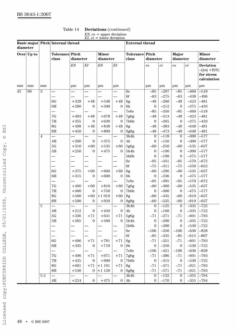
www.bzfxw.com
BS 3643-1:2007
48 • © BSI 2007
45 90 3 — — — — — 6e –85 –297 –85 –460 –518— — — — — 6f –63 –275 –63 –438 –4966G +328 +48 +548 +48 6g –48 –260 –48 –423 –4816H +280 0 +500 0 6h 0 –212 0 –375 –433— — — — — 7e6e –85 –350 –85 –460 –5187G +403 +48 +678 +48 7g6g –48 –313 –48 –423 –4817H +355 0 +630 0 7h6h 0 –265 0 –375 –4338G +498 +48 +848 +48 8g –48 –383 –48 –648 –4818H +450 0 +800 0 9g8g –48 –473 –48 –648 –481
4 — — — — — 3h4h 0 –118 0 –300 –5774H +200 0 +375 0 4h 0 –150 0 –300 –5775G +310 +60 +535 +60 5g6g –60 –250 –60 –535 –6375H +250 0 +475 0 5h4h 0 –190 0 –300 –577— — — — — 5h6h 0 –190 0 –475 –577— — — — — 6e –95 –331 –95 –570 –672— — — — — 6f –75 –311 –75 –550 –6526G +375 +60 +660 +60 6g –60 –296 –60 –535 –6376H +315 0 +600 0 6h 0 –236 0 –475 –577— — — — — 7e6e –95 –395 –95 –570 –6727G +460 +60 +810 +60 7g6g –60 –360 –60 –535 –6377H +400 0 +750 0 7h6h 0 –300 0 –475 –5778G +560 +60 +1 010 +60 8g –60 –435 –60 –810 –6378H +500 0 +950 0 9g8g –60 –535 –60 –810 –637
5 — — — — — 3h4h 0 –125 0 –335 –7224H +212 0 +450 0 4h 0 –160 0 –335 –7225G +336 +71 +631 +71 5g6g –71 –271 –71 –601 –7935H +265 0 +560 0 5h4h 0 –200 0 –335 –722— — — — — 5h6h 0 –200 0 –530 –722— — — — — 6e –106 –356 –106 –636 –828— — — — — 6f –85 –335 –85 –615 –8076G +406 +71 +781 +71 6g –71 –321 –71 –601 –7936H +335 0 +710 0 6h 0 –250 0 –530 –722— — — — — 7e6e –106 –421 –106 –636 –8287G +496 +71 +971 +71 7g6g –71 –386 –71 –601 –7937H +425 0 +900 0 7h6h 0 –315 0 –530 –7228G +601 +71 +1 191 +71 8g –71 –471 –71 –921 –7938H +530 0 +1 120 0 9g8g –71 –571 –71 –921 –793
5.5 — — — — — 3h4h 0 –132 0 –355 –7944H +224 0 +475 0 4h 0 –170 0 –355 –794
Table 14 Deviations (continued)ES, es = upper deviationEI, ei = lower deviation
Basic major diameter
Pitch Internal thread External thread
Over Up to Tolerance class
Pitch diameter
Minor diameter
Tolerance class
Pitch diameter
Major diameter
Minor diameter
ES EI ES EI es ei es ei Deviation–(|es| +H/6)for stress calculation
mm mm mm μm μm μm μm μm μm μm μm μm
Licensed copy:PONTYPRIDD COLLEGE, 05/01/2008, Uncontrolled Copy, © BSI

www.bzfxw.com
© BSI 2007 • 49
BS 3643-1:2007
45 90 5.5 5G +355 +75 +675 +75 5g6g –75 –287 –75 –635 –8695H +280 0 +600 0 5h4h 0 –212 0 –355 –794— — — — — 5h6h 0 –212 0 –560 –794— — — — — 6e –112 –377 –112 –672 –906— — — — — 6f –90 –355 –90 –650 –8846G +430 +75 +825 +75 6g –75 –340 –75 –635 –8696H +355 0 +750 0 6h 0 –265 0 –560 –794— — — — — 7e6e –112 –447 –112 –672 –9067G +525 +75 +1 025 +75 7g6g –75 –410 –75 –635 –8697H +450 0 +950 0 7h6h 0 –335 0 –560 –7948G +635 +75 +1 255 +75 8g –75 –500 –75 –975 –8698H +560 0 +1 180 0 9g8g –75 –605 –75 –975 –869
6 — — — — — 3h4h 0 –140 0 –375 –8664H +236 0 +500 0 4h 0 –180 0 –375 –8665G +380 +80 +710 +80 5g6g –80 –304 –80 –680 –9465H +300 0 +630 0 5h4h 0 –224 0 –375 –866— — — — — 5h6h 0 –224 0 –600 –866— — — — — 6e –118 –398 –118 –718 –984— — — — — 6f –95 –375 –95 –695 –9616G +455 +80 +880 +80 6g –80 –360 –80 –680 –9466H +375 0 +800 0 6h 0 –280 0 –600 –866— — — — — 7e6e –118 –473 –118 –718 –9847G +555 +80 +1 080 +80 7g6g –80 –435 –80 –680 –9467H +475 0 +1 000 0 7h6h 0 –355 0 – 600 –8668G +680 +80 +1 330 +80 8g –80 –530 –80 –1 030 –9468H +600 0 +1 250 0 9g8g –80 –640 –80 –1 030 –946
90 180 2 — — — — — 3h4h 0 –95 0 –180 –2894H +160 0 +236 0 4h 0 –118 0 –180 –2895G +238 +38 +338 +38 5g6g –38 –188 –38 –318 –3275H +200 0 +300 0 5h4h 0 –150 0 –180 –289— — — — — 5h6h 0 –150 0 –280 –289— — — — — 6e –71 –261 –71 –351 –360— — — — — 6f –52 –242 –52 –332 –3416G +288 +38 +413 +38 6g –38 –228 –38 –318 –3276H +250 0 +375 0 6h 0 –190 0 –280 –289— — — — — 7e6e –71 –307 –71 –351 –3607G +353 +38 +513 +38 7g6g –38 –274 –38 –318 –3277H +315 0 +475 0 7h6h 0 –236 0 –280 –2898G +438 +38 +638 +38 8g –38 –338 –38 –488 –3278H +400 0 +600 0 9g8g –38 –413 –38 –488 –327
Table 14 Deviations (continued)ES, es = upper deviationEI, ei = lower deviation
Basic major diameter
Pitch Internal thread External thread
Over Up to Tolerance class
Pitch diameter
Minor diameter
Tolerance class
Pitch diameter
Major diameter
Minor diameter
ES EI ES EI es ei es ei Deviation–(|es| +H/6)for stress calculation
mm mm mm μm μm μm μm μm μm μm μm μm
Licensed copy:PONTYPRIDD COLLEGE, 05/01/2008, Uncontrolled Copy, © BSI

www.bzfxw.com
BS 3643-1:2007
50 • © BSI 2007
90 180 3 — — — — — 3h4h 0 –112 0 –236 –4334H +190 0 +315 0 4h 0 –140 0 –236 –4335G +284 +48 +448 +48 5g6g –48 –228 –48 –423 –4815H +236 0 +400 0 5h4h 0 –180 0 –236 –433— — — — — 5h6h 0 –180 0 –375 –433— — — — — 6e –85 –309 –85 –460 –518— — — — — 6f –63 –287 –63 –438 –4966G +348 +48 +548 +48 6g –48 –272 –48 –423 –4816H +300 0 +500 0 6h 0 –224 0 –375 –433— — — — — 7e6e –85 –365 –85 –460 –5187G +423 +48 +678 +48 7g6g –48 –328 –48 –423 –4817H +375 0 +630 0 7h6h 0 –280 0 –375 –4338G +523 +48 +848 +48 8g –48 –403 –48 –648 –4818H +475 0 +800 0 9g8g –48 –498 –48 –648 –481
4 — — — — — 3h4h 0 –125 0 –300 –5774H +212 0 +375 0 4h 0 –160 0 –300 –5775G +325 +60 +535 +60 5g6g –60 –260 –60 –535 –6375H +265 0 +475 0 5h4h 0 –200 0 –300 –577— — — — — 5h6h 0 –200 0 –475 –577— — — — — 6e –95 –345 –95 –570 –672— — — — — 6f –75 –325 –75 –550 –6526G +395 +60 +660 +60 6g –60 –310 –60 –535 –6376H +335 0 +600 0 6h 0 –250 0 –475 –577— — — — — 7e6e –95 –410 –95 –570 –6727G +485 +60 +810 +60 7g6g –60 –375 –60 –535 –6377H +425 0 +750 0 7h6h 0 –315 0 –475 –5778G +590 +60 +1 010 +60 8g –60 –460 –60 –810 –6378H +530 0 +950 0 9g8g –60 –560 –60 –810 –637
6 — — — — — 3h4h 0 –150 0 –375 –8664H +250 0 +500 0 4h 0 –190 0 –375 –8665G +395 +80 +710 +80 5g6g –80 –316 –80 –680 –9465H +315 0 +630 0 5h4h 0 –236 0 –375 –866— — — — — 5h6h 0 –236 0 –600 –866— — — — — 6e –118 –418 –118 –718 –984— — — — — 6f –95 –395 –95 –695 –9616G +480 +80 +880 +80 6g –80 –380 –80 –680 –9466H +400 0 +800 0 6h 0 –300 0 –600 –866— — — — — 7e6e –118 –493 –118 –718 –984
7G +580 +80 +1 080 +80 7g6g –80 –455 –80 –680 –9467H +500 0 +1 000 0 7h6h 0 –375 0 –600 –8668G +710 +80 +1 330 +80 8g –80 –555 –80 –1 030 –9468H +630 0 +1 250 0 9g8g –80 –680 –80 –1 030 –946
Table 14 Deviations (continued)ES, es = upper deviationEI, ei = lower deviation
Basic major diameter
Pitch Internal thread External thread
Over Up to Tolerance class
Pitch diameter
Minor diameter
Tolerance class
Pitch diameter
Major diameter
Minor diameter
ES EI ES EI es ei es ei Deviation–(|es| +H/6)for stress calculation
mm mm mm μm μm μm μm μm μm μm μm μm
Licensed copy:PONTYPRIDD COLLEGE, 05/01/2008, Uncontrolled Copy, © BSI

www.bzfxw.com
© BSI 2007 • 51
BS 3643-1:2007
90 180 8 A) — — — — — 3h4h 0 –170 0 –450 –1 1554H +280 0 +630 0 4h 0 –212 0 –450 –1 1555G +380 +100 +900 +100 5g6g –100 –365 –100 –810 –1 2555H +355 0 +800 0 5h4h 0 –265 0 –450 –1 155— — — — — 5h6h 0 –265 0 –710 –1 155— — — — — 6e –140 –475 –140 –850 –1 295— — — — — 6f –118 –453 –118 –828 –1 2736G +550 +100 +1 100 +100 6g –100 –435 –100 –810 –1 2556H +450 0 +1 000 0 6h 0 –335 0 –710 –1 155— — — — — 7e6e –140 –565 –140 –850 –1 2957G +660 +100 +1 350 +100 7g6g –100 –525 –100 –810 –1 2557H +560 0 +1 250 0 7h6h 0 –425 0 –710 –1 1558G +810 +100 +1 700 +100 8g –100 –630 –100 –1 280 –1 2558H +710 0 +1 600 0 9g8g –100 –770 –100 –1 280 –1 255
180 355 3 — — — — — 3h4h 0 –125 0 –236 –4334H +212 0 +315 0 4h 0 –160 0 –236 –4335G +313 +48 +448 +48 5g6g –48 –248 –48 –423 –4815H +265 0 +400 0 5h4h 0 –200 0 –236 –433— — — — — 5h6h 0 –200 0 –375 –433— — — — — 6e –85 –335 –85 –460 –518— — — — — 6f –63 –313 –63 –438 –4966G +383 +48 +548 +48 6g –48 –298 –48 –423 –4816H +335 0 +500 0 6h 0 –250 0 –375 –433— — — — — 7e6e –85 –400 –85 –460 –5187G +473 +48 +678 +48 7g6g –48 –363 –48 –423 –4817H +425 0 +630 0 7h6h 0 –315 0 –375 –4338G +578 +48 +848 +48 8g –48 –448 –48 –648 –4818H +530 0 +800 0 9g8g –48 –548 –48 –648 –481
4 — — — — — 3h4h 0 –140 0 –300 –5774H +236 0 +375 0 4h 0 –180 0 –300 –5775G +360 +60 +535 +60 5g6g –60 –284 –60 –535 –6375H +300 0 +475 0 5h4h 0 –224 0 –300 –577— — — — — 5h6h 0 –224 0 –475 –577— — — — — 6e –95 –375 –95 –570 –672— — — — — 6f –75 –355 –75 –550 –6526G +435 +60 +660 +60 6g –60 –340 –60 –535 –6376H +375 0 +600 0 6h 0 –280 0 –475 –577— — — — — 7e6e –95 –450 –95 –570 –6727G +535 +60 +810 +60 7g6g –60 –415 –60 –535 –6377H +475 0 +750 0 7h6h 0 –355 0 –475 –5778G +660 +60 +1 010 +60 8g –60 –510 –60 –810 –6378H +600 0 +950 0 9g8g –60 –620 –60 –810 –637
A) Pitch 8 mm applies only to basic major diameters M125 and larger.
Table 14 Deviations (continued)ES, es = upper deviationEI, ei = lower deviation
Basic major diameter
Pitch Internal thread External thread
Over Up to Tolerance class
Pitch diameter
Minor diameter
Tolerance class
Pitch diameter
Major diameter
Minor diameter
ES EI ES EI es ei es ei Deviation–(|es| +H/6)for stress calculation
mm mm mm μm μm μm μm μm μm μm μm μm
Licensed copy:PONTYPRIDD COLLEGE, 05/01/2008, Uncontrolled Copy, © BSI

www.bzfxw.com
BS 3643-1:2007
52 • © BSI 2007
180 355 6 — — — — — 3h4h 0 –160 0 –375 –8664H +265 0 +500 0 4h 0 –200 0 –375 –8665G +415 +80 +710 +80 5g6g –80 –330 –80 –680 –9465H +335 0 +630 0 5h4h 0 –250 0 –375 –866— — — — — 5h6h 0 –250 0 –600 –866— — — — — 6e –118 –433 –118 –718 –984— — — — — 6f –95 –410 –95 –695 –9616G +505 +80 +880 +80 6g –80 –395 –80 –680 –9466H +425 0 +800 0 6h 0 –315 0 –600 –866— — — — — 7e6e –118 –518 –118 –718 –9847G +610 +80 +1 080 +80 7g6g –80 –480 –80 –680 –9467H +530 0 +1 000 0 7h6h 0 –400 0 –600 –8668G +750 +80 +1 330 +80 8g –80 –580 –80 –1 030 –9468H +670 0 +1 250 0 9g8g –80 –710 –80 –1 030 –946
8 — — — — — 3h4h 0 –180 0 –450 –1 1554H +300 0 +630 0 4h 0 –224 0 –450 –1 1555G +475 +100 +900 +100 5g6g –100 –380 –100 –810 –1 2555H +375 0 +800 0 5h4h 0 –280 0 –450 –1 155— — — — — 5h6h 0 –280 0 –710 –1 155— — — — — 6e –140 –495 –140 –850 –1 295 — — — — — 6f –118 –473 –118 –828 –1 2736G +575 +100 +1 100 +100 6g –100 –455 –100 –810 –1 2556H +475 0 +1 000 0 6h 0 –355 0 –710 –1 155— — — — — 7e6e –140 –590 –140 –850 –1 2957G +700 +100 +1 350 +100 7g6g –100 –550 –100 –810 –1 2557H +600 0 +1 250 0 7h6h 0 –450 0 –710 –1 1558G +850 +100 +1 700 +100 8g –100 –660 –100 –1 280 –1 2558H +750 0 +1 600 0 9g8g –100 –810 –100 –1 280 –1 255
Table 14 Deviations (continued)ES, es = upper deviationEI, ei = lower deviation
Basic major diameter
Pitch Internal thread External thread
Over Up to Tolerance class
Pitch diameter
Minor diameter
Tolerance class
Pitch diameter
Major diameter
Minor diameter
ES EI ES EI es ei es ei Deviation–(|es| +H/6)for stress calculation
mm mm mm μm μm μm μm μm μm μm μm μm
Licensed copy:PONTYPRIDD COLLEGE, 05/01/2008, Uncontrolled Copy, © BSI
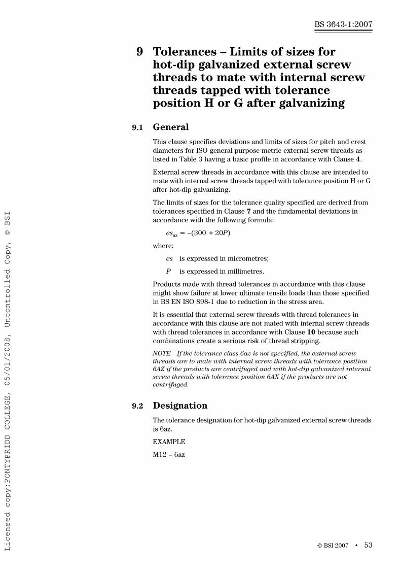
www.bzfxw.com
© BSI 2007 • 53
BS 3643-1:2007
9 Tolerances – Limits of sizes for hot-dip galvanized external screw threads to mate with internal screw threads tapped with tolerance position H or G after galvanizing
9.1 GeneralThis clause specifies deviations and limits of sizes for pitch and crest diameters for ISO general purpose metric external screw threads as listed in Table 3 having a basic profile in accordance with Clause 4.
External screw threads in accordance with this clause are intended to mate with internal screw threads tapped with tolerance position H or G after hot-dip galvanizing.
The limits of sizes for the tolerance quality specified are derived from tolerances specified in Clause 7 and the fundamental deviations in accordance with the following formula:
esaz = −(300 + 20P)
where:
es is expressed in micrometres;
P is expressed in millimetres.
Products made with thread tolerances in accordance with this clause might show failure at lower ultimate tensile loads than those specified in BS EN ISO 898-1 due to reduction in the stress area.
It is essential that external screw threads with thread tolerances in accordance with this clause are not mated with internal screw threads with thread tolerances in accordance with Clause 10 because such combinations create a serious risk of thread stripping.
NOTE If the tolerance class 6az is not specified, the external screw threads are to mate with internal screw threads with tolerance position 6AZ if the products are centrifuged and with hot-dip galvanized internal screw threads with tolerance position 6AX if the products are not centrifuged.
9.2 DesignationThe tolerance designation for hot-dip galvanized external screw threads is 6az.
EXAMPLE
M12 – 6az
Licensed copy:PONTYPRIDD COLLEGE, 05/01/2008, Uncontrolled Copy, © BSI

www.bzfxw.com
BS 3643-1:2007
54 • © BSI 2007
9.3 DeviationsThe deviations for hot-dip galvanized external screw threads as specified in Table 15 are derived from the following formula for fundamental deviations and from tolerances specified in Clause 7.
The fundamental deviations, esaz, have been calculated in accordance with the following formula:
esaz = − (300 + 20P)
where:
esaz is expressed in micrometres;
P is expressed in millimetres.
9.4 Limits of sizes – External screw threads – Coarse thread seriesTolerance quality: medium.
Thread engagement group: normal.
Tolerance class: 6az
The actual root contour shall not at any point transgress the basic profile.
For hot-dip galvanized screw threads, the tolerances apply to the parts before galvanizing. After galvanizing, the actual thread profile shall not at any point transgress the maximum material limits for tolerance position h and are intended to mate with internal screw threads of tolerance position H or G only.
Limits of sizes are given in Table 16.
Table 15 Deviations for hot-dip galvanized external threads
Thread Pitch External thread tolerance class 6az
P Pitch diameter Major diameter Minor diameter
es ei es ei Deviations for stress calculation
mm μm μm μm μm μm
M10 1.5 −330 −462 −330 −566 −547
M12 1.75 −335 −485 −335 −600 −588
M14, M16 2 −340 −500 −340 −620 −629
M18, M20, M22 2.5 −350 −520 −350 −685 −711
M24, M27 3 −360 −560 −360 −735 −793
M30, M33 3.5 −370 −582 −370 −795 −875
M36, M39 4 −380 −604 −380 −855 −957
M42, M45 4.5 −390 −626 −390 −890 −1 040
M48, M52 5 −400 −650 −400 −930 −1 122
M56, M60 5.5 −410 −675 −410 −970 −1 204
M64 6 −420 −700 −420 −1 020 −1 286
Licensed copy:PONTYPRIDD COLLEGE, 05/01/2008, Uncontrolled Copy, © BSI
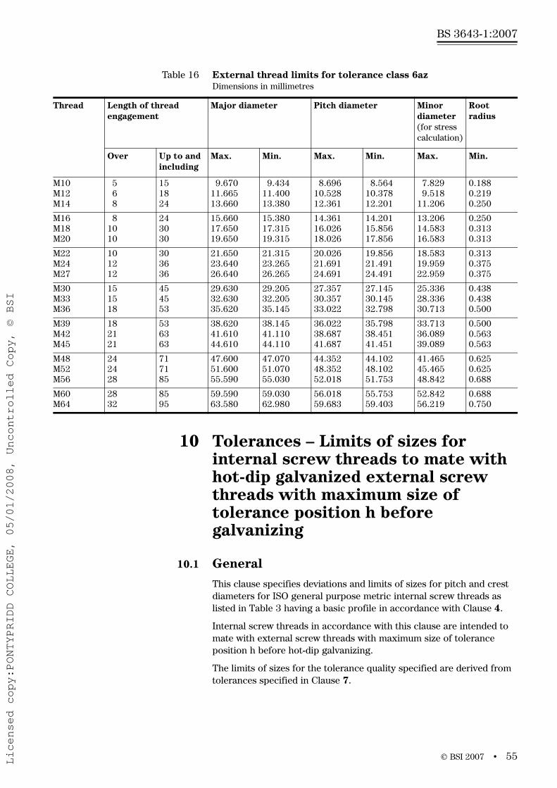
© BSI 2007 • 55
BS 3643-1:2007
10 Tolerances – Limits of sizes for internal screw threads to mate with hot-dip galvanized external screw threads with maximum size of tolerance position h before galvanizing
10.1 GeneralThis clause specifies deviations and limits of sizes for pitch and crest diameters for ISO general purpose metric internal screw threads as listed in Table 3 having a basic profile in accordance with Clause 4.
Internal screw threads in accordance with this clause are intended to mate with external screw threads with maximum size of tolerance position h before hot-dip galvanizing.
The limits of sizes for the tolerance quality specified are derived from tolerances specified in Clause 7.
Table 16 External thread limits for tolerance class 6azDimensions in millimetres
Thread Length of thread engagement
Major diameter Pitch diameter Minor diameter (for stress calculation)
Root radius
Over Up to and including
Max. Min. Max. Min. Max. Min.
M10M12M14
568
151824
9.67011.66513.660
9.43411.40013.380
8.69610.52812.361
8.56410.37812.201
7.829 9.518
11.206
0.1880.2190.250
M16M18M20
81010
243030
15.66017.65019.650
15.38017.31519.315
14.36116.02618.026
14.20115.85617.856
13.20614.58316.583
0.2500.3130.313
M22M24M27
101212
303636
21.65023.64026.640
21.31523.26526.265
20.02621.69124.691
19.85621.49124.491
18.58319.95922.959
0.3130.3750.375
M30M33M36
151518
454553
29.63032.63035.620
29.20532.20535.145
27.35730.35733.022
27.14530.14532.798
25.33628.33630.713
0.4380.4380.500
M39M42M45
182121
536363
38.62041.61044.610
38.14541.11044.110
36.02238.68741.687
35.79838.45141.451
33.71336.08939.089
0.5000.5630.563
M48M52M56
242428
717185
47.60051.60055.590
47.07051.07055.030
44.35248.35252.018
44.10248.10251.753
41.46545.46548.842
0.6250.6250.688
M60M64
2832
8595
59.59063.580
59.03062.980
56.01859.683
55.75359.403
52.84256.219
0.6880.750
Licensed copy:PONTYPRIDD COLLEGE, 05/01/2008, Uncontrolled Copy, © BSI

BS 3643-1:2007
56 • © BSI 2007
The fundamental deviations for internal screw threads with a tolerance position AZ have been calculated in accordance with the following formula:
EIAZ = +(300 + 20P)
where:
EI is expressed in micrometres;
P is expressed in millimetres.
The fundamental deviations for internal screw threads with a tolerance position AX have been calculated in accordance with the following formula:
EIAX = +(220P − 20)
where:
EI is expressed in micrometres;
P is expressed in millimetres.
Products made with thread tolerances in accordance with this clause might show load failure when tested in accordance with BS EN 20898-2 without adjustment of other mechanical properties.
It is essential that internal screw threads with thread tolerances in accordance with this clause are not mated with external screw threads with thread tolerances in accordance with Clause 9 because such combinations create a serious risk of thread stripping.
NOTE Internal screw threads with tolerance class 6AZ are primarily intended to mate with external screw threads centrifuged after hot-dip galvanizing. Internal screw threads with tolerance class 6AX are primarily intended to mate with hot-dip galvanized external screw threads with heavy coating not centrifuged.
10.2 DesignationThe tolerance designation for internal screw threads to mate with hot-dip galvanized external screw threads with maximum size of tolerance position h before galvanizing is 6AZ or 6AX.
EXAMPLES
M12 – 6AZ
M12 – 6AX
10.3 DeviationsThe deviations for internal screw threads to mate with hot-dip galvanized external screw threads, as specified in Table 17 are derived from the following formulae for fundamental deviations and from tolerances specified in Clause 7.
The fundamental deviations, EIAZ and EIAX have been calculated in accordance with the following formulae:
EIAZ = +(300 + 20P)
EIAX = +(220P − 20)
where:
EI is expressed in micrometres;
P is expressed in millimetres.
Licensed copy:PONTYPRIDD COLLEGE, 05/01/2008, Uncontrolled Copy, © BSI
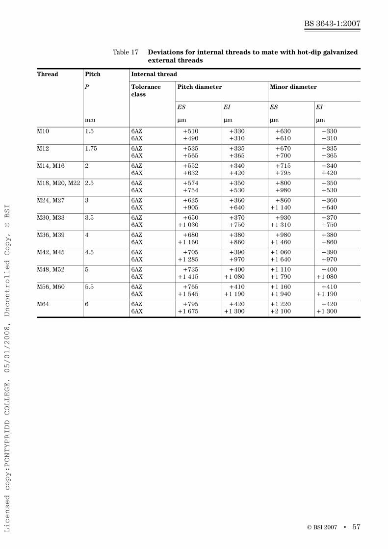
© BSI 2007 • 57
BS 3643-1:2007
Table 17 Deviations for internal threads to mate with hot-dip galvanized external threads
Thread Pitch Internal thread
P Tolerance class
Pitch diameter Minor diameter
ES EI ES EI
mm μm μm μm μm
M10 1.5 6AZ6AX
+510 +490
+330 +310
+630 +610
+330 +310
M12 1.75 6AZ6AX
+535 +565
+335 +365
+670 +700
+335 +365
M14, M16 2 6AZ6AX
+552 +632
+340 +420
+715 +795
+340 +420
M18, M20, M22 2.5 6AZ6AX
+574 +754
+350 +530
+800 +980
+350 +530
M24, M27 3 6AZ6AX
+625 +905
+360 +640
+860+1 140
+360 +640
M30, M33 3.5 6AZ6AX
+650+1 030
+370 +750
+930+1 310
+370 +750
M36, M39 4 6AZ6AX
+680+1 160
+380 +860
+980+1 460
+380 +860
M42, M45 4.5 6AZ6AX
+705+1 285
+390 +970
+1 060+1 640
+390 +970
M48, M52 5 6AZ6AX
+735+1 415
+400+1 080
+1 110+1 790
+400+1 080
M56, M60 5.5 6AZ6AX
+765+1 545
+410+1 190
+1 160+1 940
+410+1 190
M64 6 6AZ6AX
+795+1 675
+420+1 300
+1 220+2 100
+420+1 300
Licensed copy:PONTYPRIDD COLLEGE, 05/01/2008, Uncontrolled Copy, © BSI

BS 3643-1:2007
58 • © BSI 2007
10.4 Limits of sizes – Internal screw threads – Coarse thread seriesTolerance quality: medium.
Thread engagement group: normal.
Tolerance classes: 6AZ and 6AX.
Limits of sizes are given in Table 18 and Table 19.
Table 18 Internal screw thread limits for tolerance class 6AZDimensions in millimetres
Thread Length of thread engagement
Major diameter A)
Pitch diameter A) Minor diameter C)
Over Up to and including
Min.B) Max. Min. Max. Min.
M10M12M14
568
151824
10.33012.33514.340
9.53611.39813.253
9.35611.19813.041
9.00610.77612.550
8.70610.44112.175
M16M18M20
81010
243030
16.34018.35020.350
15.25316.95018.950
15.04116.72618.726
14.55016.09418.094
14.17515.64417.644
M22M24M27
101212
303636
22.35024.36027.360
20.95022.67625.676
20.72622.41125.411
20.09421.61224.612
19.64421.11224.112
M30M33M36
151518
454553
30.37033.37036.380
28.37731.37734.082
28.09731.09733.782
27.14130.14132.650
26.58129.58132.050
M39M42M45
182121
536363
39.38042.39045.390
37.08239.78242.782
36.78239.46742.467
35.65038.18941.189
35.05037.51940.519
M48M52M56
242428
717185
48.40052.40056.410
45.48749.48753.193
45.15249.15252.838
43.69746.69751.206
42.98746.98750.456
M60M64
2832
8595
60.41064.420
57.19360.898
56.83860.523
55.20658.725
54.45657.925
A) Dimensions apply to internal screw threads after galvanizing and tapping oversize.B) Refers to the imaginary coaxial cylinder through the points where the requirement with regard to straightness of flank
ceases.C) Dimensions apply to internal screw threads before galvanizing or after galvanizing and removal of zinc fragments.
Licensed copy:PONTYPRIDD COLLEGE, 05/01/2008, Uncontrolled Copy, © BSI
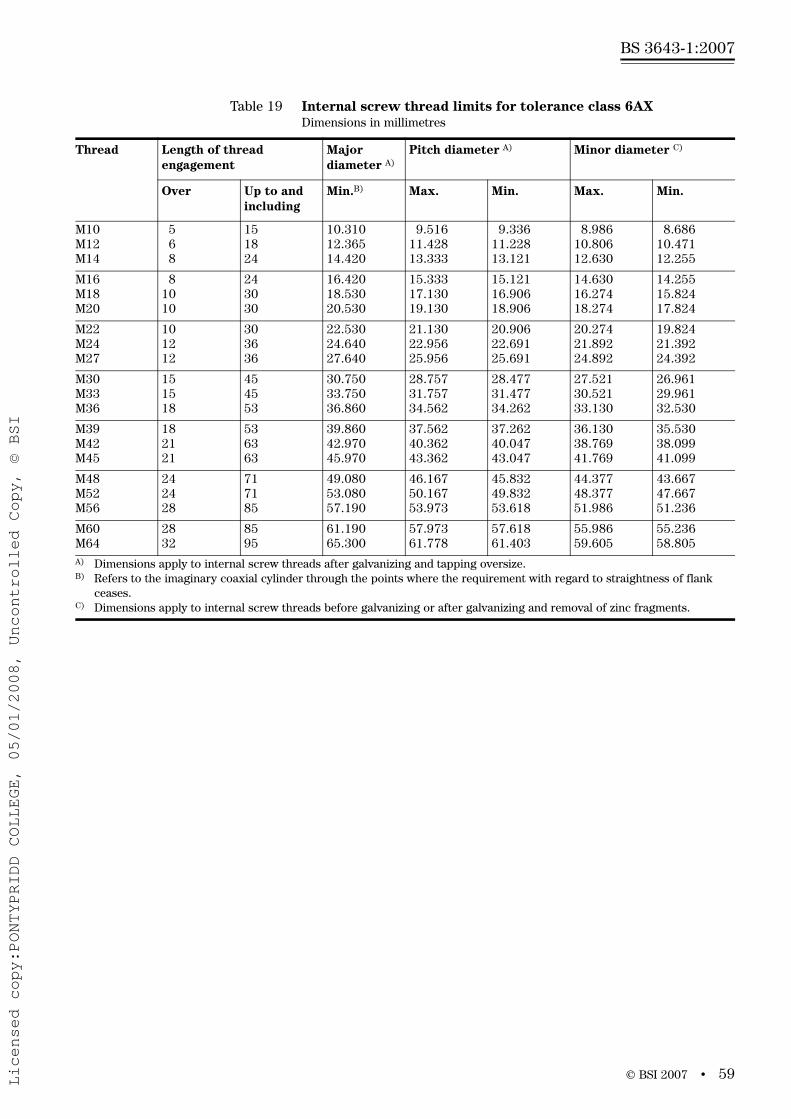
© BSI 2007 • 59
BS 3643-1:2007
Table 19 Internal screw thread limits for tolerance class 6AXDimensions in millimetres
Thread Length of thread engagement
Major diameter A)
Pitch diameter A) Minor diameter C)
Over Up to and including
Min.B) Max. Min. Max. Min.
M10M12M14
568
151824
10.31012.36514.420
9.51611.42813.333
9.33611.22813.121
8.98610.80612.630
8.68610.47112.255
M16M18M20
81010
243030
16.42018.53020.530
15.33317.13019.130
15.12116.90618.906
14.63016.27418.274
14.25515.82417.824
M22M24M27
101212
303636
22.53024.64027.640
21.13022.95625.956
20.90622.69125.691
20.27421.89224.892
19.82421.39224.392
M30M33M36
151518
454553
30.75033.75036.860
28.75731.75734.562
28.47731.47734.262
27.52130.52133.130
26.96129.96132.530
M39M42M45
182121
536363
39.86042.97045.970
37.56240.36243.362
37.26240.04743.047
36.13038.76941.769
35.53038.09941.099
M48M52M56
242428
717185
49.08053.08057.190
46.16750.16753.973
45.83249.83253.618
44.37748.37751.986
43.66747.66751.236
M60M64
2832
8595
61.19065.300
57.97361.778
57.61861.403
55.98659.605
55.23658.805
A) Dimensions apply to internal screw threads after galvanizing and tapping oversize.B) Refers to the imaginary coaxial cylinder through the points where the requirement with regard to straightness of flank
ceases.C) Dimensions apply to internal screw threads before galvanizing or after galvanizing and removal of zinc fragments.
Licensed copy:PONTYPRIDD COLLEGE, 05/01/2008, Uncontrolled Copy, © BSI
BS 3643-1:2007
60 • © BSI 2007
Annex A (informative) Notes for guidance
A.1 Maximum material profileThe maximum material profiles of an internal thread and an external thread are illustrated in Figure A.1. These profiles have been established from the basic profile given in Clause 4.
A.2 CoatingsInformation on tolerance positions G, e, f and g, which provide clearance fits which may be used to accommodate coatings is given in Clause 7.
BS EN ISO 4042:2000 includes tables listing pitches and tolerance positions and the maximum thickness of coating that can be accommodated by each.
A.3 External threads – Stress areasThe stress area, As, for an external thread can be calculated from the following equation:
where:
d2 is the basic pitch diameter;
d3 is the minor diameter as given by the equation:
where:
d1 is the basic minor diameter;
H is the height of the fundamental triangle.
Nominal stress areas for external screw threads specified in this part of BS 3643 are given in Table A.1 and Table A.2.
A.4 External threads – Minor diametersMinor diameters for external threads can be calculated using the information given in 7.9.
The minimum minor diameters are given in the tables in BS 3643-2. In the case of the maximum minor diameters, it is essential that these are less than the minimum minor diameter of the GO gauges in accordance with BS 919-3.
22 3
sπ4 2
d dA
+⎛ ⎞= ⎜ ⎟⎝ ⎠
3 1 6H
d d= −
Licensed copy:PONTYPRIDD COLLEGE, 05/01/2008, Uncontrolled Copy, © BSI

© B
SI 2007•
61
BS 3643-1:2007
Figure A.1 Maximum material profiles for internal and external threads
NOTE In practice the root is rounded and cleared beyond a width of P/8.
a) Internal thread
SeeNote
P
P/2
(5/8
) H
Pitch line
P/4
H/8
H/4
H/4
H
Axis of screw thread
P/8
90
3030
Licensed copy:PONTYPRIDD COLLEGE, 05/01/2008, Uncontrolled Copy, © BSI

62•
© B
SI 2007
BS 3643-1:2007
Figure A.1 Maximum material profiles for internal and external threads (continued)
NOTE 1 In practice crests of external threads may be rounded inside the maximum profile.
NOTE 2 See 7.9.
b) External thread
SeeNote 1
Pitch line
H/8
H/4
H
Axis of screw thread
P/8
90
3030
P
P/2(5
/8) H
SeeNote 2
(3/8
) H
Licensed copy:PONTYPRIDD COLLEGE, 05/01/2008, Uncontrolled Copy, © BSI

© BSI 2007 • 63
BS 3643-1:2007
Table A.1 Nominal stress areas for external screw threads – Coarse series
Nominal thread diametermm
Pitch of the thread Nominal stress area
mm mm2
1 0.25 0.46
1.1 0.25 0.59
1.2 0.25 0.73
1.4 0.3 0.98
1.6 0.35 1.27
1.8 0.35 1.7
2 0.4 2.07
2.2 0.45 2.48
2.5 0.45 3.39
3 0.5 5.03
3.5 0.6 6.78
4 0.7 8.78
5 0.8 14.2
6 1 20.1
7 1 28.9
8 1.25 36.6
10 1.5 58.0
12 1.75 84.3
14 2 115
16 2 157
18 2.5 192
20 2.5 245
22 2.5 303
24 3 353
27 3 459
30 3.5 561
33 3.5 694
36 4 817
39 4 976
42 4.5 1 121
45 4.5 1 306
48 5 1 473
52 5 1 758
56 5.5 2 030
60 5.5 2 362
64 6 2 676
68 6 3 055
Licensed copy:PONTYPRIDD COLLEGE, 05/01/2008, Uncontrolled Copy, © BSI

BS 3643-1:2007
64 • © BSI 2007
Table A.2 Nominal stress areas for external screw threads – Fine series
Nominal thread diametermm
Pitch of the thread Nominal stress area
mm mm2
1 0.2 0.52
1.1 0.2 0.65
1.2 0.2 0.81
1.4 0.2 1.16
1.6 0.2 1.57
1.8 0.2 2.04
2 0.25 2.45
2.2 0.25 3.03
2.5 0.35 3.71
3 0.35 5.61
3.5 0.35 7.90
4 0.5 9.79
4.5 0.5 12.8
5 0.5 16.1
6 0.75 22
7 0.75 31.3
8 1 39.2
10 1.25 61.2
12 1.25 92.1
14 1.5 125
16 1.5 167
18 1.5 216
20 1.5 272
22 1.5 333
24 2 384
27 2 496
30 2 621
33 2 761
Licensed copy:PONTYPRIDD COLLEGE, 05/01/2008, Uncontrolled Copy, © BSI
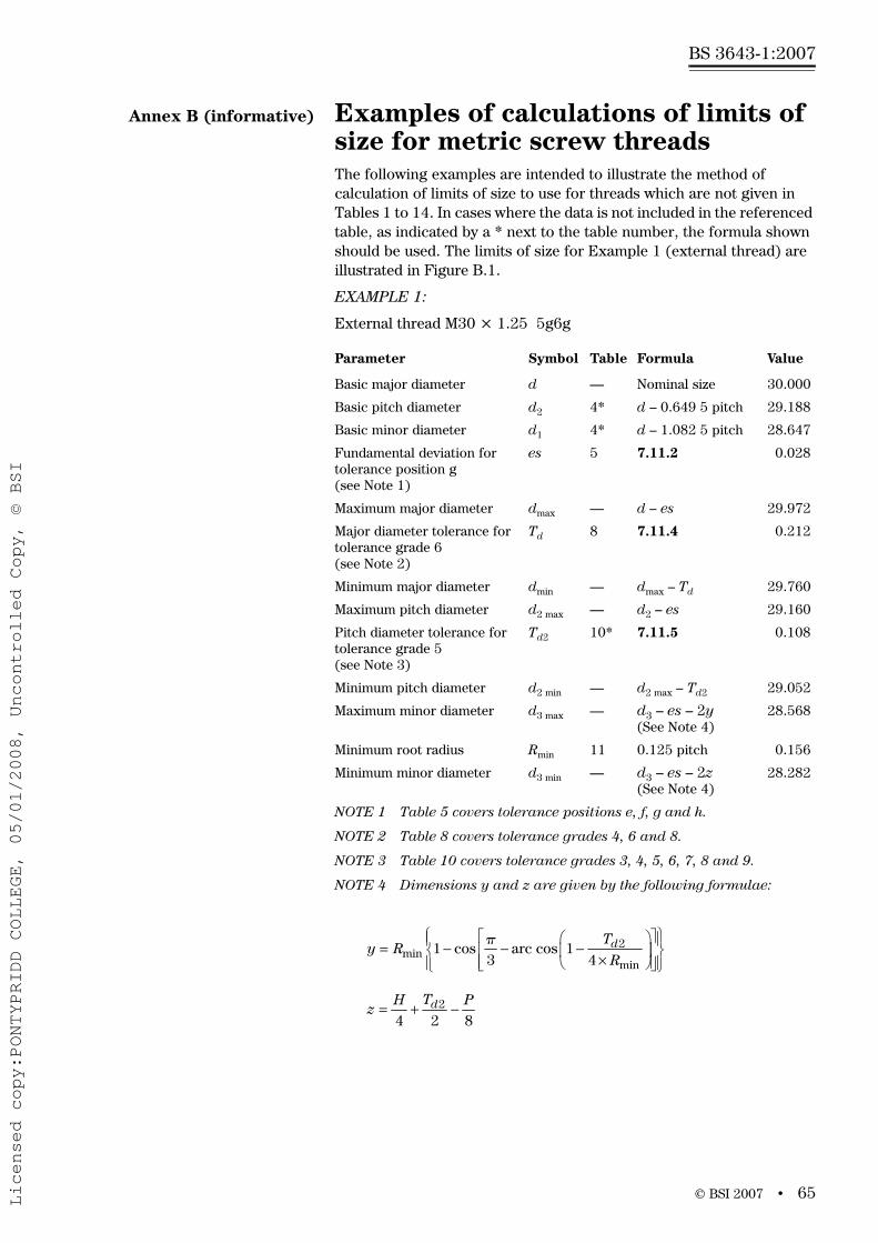
© BSI 2007 • 65
BS 3643-1:2007
Annex B (informative) Examples of calculations of limits of size for metric screw threads The following examples are intended to illustrate the method of calculation of limits of size to use for threads which are not given in Tables 1 to 14. In cases where the data is not included in the referenced table, as indicated by a * next to the table number, the formula shown should be used. The limits of size for Example 1 (external thread) are illustrated in Figure B.1.
EXAMPLE 1:
External thread M30 × 1.25 5g6g
Parameter Symbol Table Formula Value
Basic major diameter d — Nominal size 30.000
Basic pitch diameter d2 4* d – 0.649 5 pitch 29.188
Basic minor diameter d1 4* d – 1.082 5 pitch 28.647
Fundamental deviation for tolerance position g (see Note 1)
es 5 7.11.2 0.028
Maximum major diameter dmax — d – es 29.972
Major diameter tolerance for tolerance grade 6 (see Note 2)
Td 8 7.11.4 0.212
Minimum major diameter dmin — dmax – Td 29.760
Maximum pitch diameter d2 max — d2 – es 29.160
Pitch diameter tolerance for tolerance grade 5 (see Note 3)
Td2 10* 7.11.5 0.108
Minimum pitch diameter d2 min — d2 max – Td2 29.052
Maximum minor diameter d3 max — d3 – es – 2y(See Note 4)
28.568
Minimum root radius Rmin 11 0.125 pitch 0.156
Minimum minor diameter d3 min — d3 – es – 2z(See Note 4)
28.282
NOTE 1 Table 5 covers tolerance positions e, f, g and h.
NOTE 2 Table 8 covers tolerance grades 4, 6 and 8.
NOTE 3 Table 10 covers tolerance grades 3, 4, 5, 6, 7, 8 and 9.
NOTE 4 Dimensions y and z are given by the following formulae:
2min
min
π1 cos arc cos 1
3 4dT
y RR
⎧ ⎫⎡ ⎤⎛ ⎞⎪ ⎪= − − −⎢ ⎥⎨ ⎬⎜ ⎟×⎢ ⎥⎝ ⎠⎪ ⎪⎣ ⎦⎩ ⎭
24 2 8
dTH Pz = + −
Licensed copy:PONTYPRIDD COLLEGE, 05/01/2008, Uncontrolled Copy, © BSI

BS 3643-1:2007
66 • © BSI 2007
The maximum root profile shown in Figure 8 (see 7.9) and used for the calculation of the maximum minor diameter is theoretically possible but unlikely to occur in practice, since it would require the combination of maximum truncation at minor diameter and minimum material position on the thread flanks.
The maximum minor diameter is not normally specified as part of the thread summary.
Summary:
External thread M30 × 1.25 – 5g6g
Major diameter 29.972 – 29.760
Pitch diameter 29.160 – 29.052
Minor diameter 28.568 – 28.282
Figure B.1 Illustration of limits of size for external thread (see Example 1)
H/4
Go-gauge profilem
inc
max
c3max
d
y
z
3min
d T
/2d2
R min
R min
Licensed copy:PONTYPRIDD COLLEGE, 05/01/2008, Uncontrolled Copy, © BSI
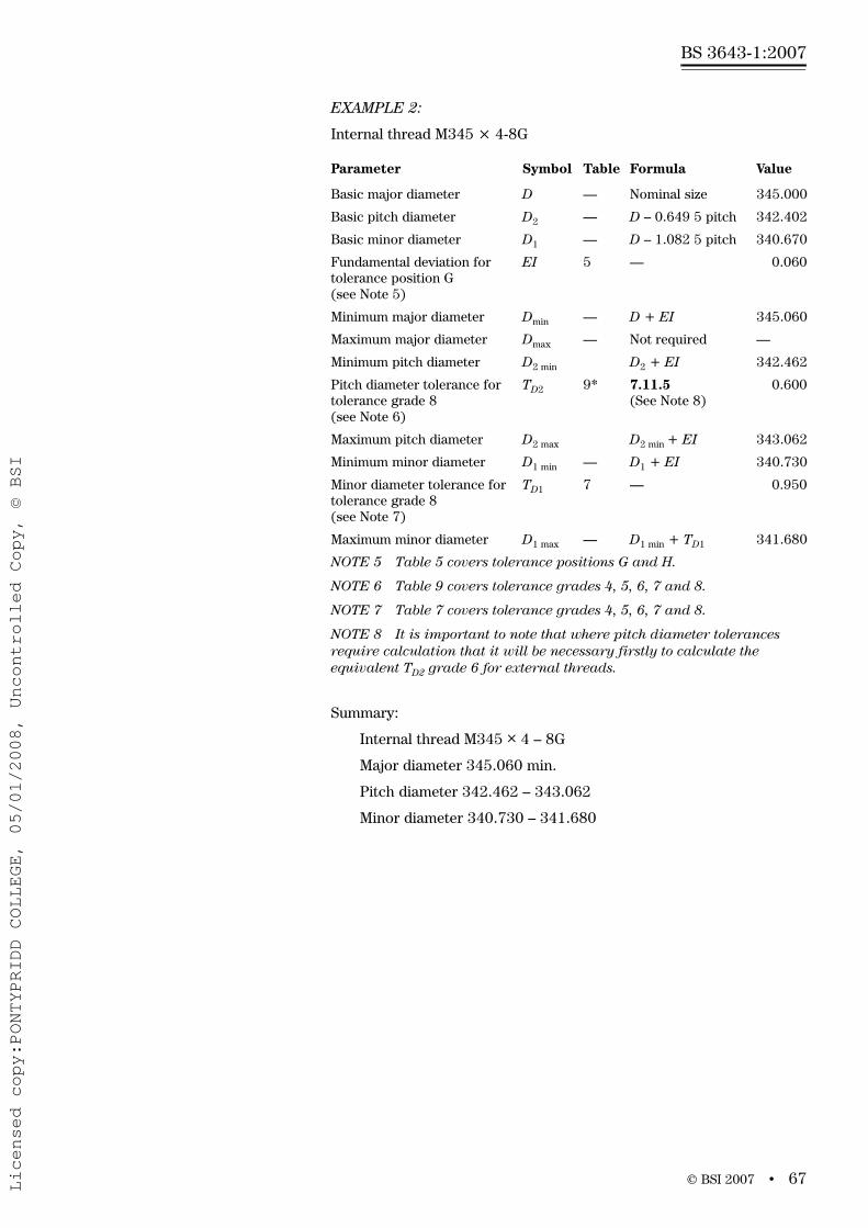
© BSI 2007 • 67
BS 3643-1:2007
EXAMPLE 2:
Internal thread M345 × 4-8G
Summary:
Internal thread M345 × 4 – 8G
Major diameter 345.060 min.
Pitch diameter 342.462 – 343.062
Minor diameter 340.730 – 341.680
Parameter Symbol Table Formula Value
Basic major diameter D — Nominal size 345.000
Basic pitch diameter D2 — D – 0.649 5 pitch 342.402
Basic minor diameter D1 — D – 1.082 5 pitch 340.670
Fundamental deviation for tolerance position G (see Note 5)
EI 5 — 0.060
Minimum major diameter Dmin — D + EI 345.060
Maximum major diameter Dmax — Not required —
Minimum pitch diameter D2 min D2 + EI 342.462
Pitch diameter tolerance for tolerance grade 8 (see Note 6)
TD2 9* 7.11.5(See Note 8)
0.600
Maximum pitch diameter D2 max D2 min + EI 343.062
Minimum minor diameter D1 min — D1 + EI 340.730
Minor diameter tolerance for tolerance grade 8 (see Note 7)
TD1 7 — 0.950
Maximum minor diameter D1 max — D1 min + TD1 341.680
NOTE 5 Table 5 covers tolerance positions G and H.
NOTE 6 Table 9 covers tolerance grades 4, 5, 6, 7 and 8.
NOTE 7 Table 7 covers tolerance grades 4, 5, 6, 7 and 8.
NOTE 8 It is important to note that where pitch diameter tolerances require calculation that it will be necessary firstly to calculate the equivalent TD2 grade 6 for external threads.
Licensed copy:PONTYPRIDD COLLEGE, 05/01/2008, Uncontrolled Copy, © BSI

BS 3643-1:2007
68 • © BSI 2007
BibliographyStandards publications
For dated references, only the edition cited applies. For undated references, the latest edition of the referenced document (including any amendments) applies.
BS 3643-2, ISO metric screw threads – Part 2: Specification for selected limits of size
BS EN 20898-2, Mechanical properties of fasteners – Part 2: Nuts with specified proof load values – Coarse thread
BS ISO 68-1, ISO general purpose screw threads – Basic profile – Part 1: Metric screw threads
BS ISO 261, ISO general purpose metric screw threads – General plan
BS ISO 262, ISO general purpose metric screw threads – Selected sizes for screws, bolts and nuts
BS ISO 965-1, ISO general purpose metric screw threads – Tolerances – Part 1: Principles and basic data
BS ISO 965-3, ISO general purpose metric screw threads – Tolerances – Part 3: Deviations for constructional screw threads
BS ISO 965-4, ISO general purpose metric screw threads – Tolerances – Part 4: Limits of sizes for hot-dip galvanized external screw threads to mate with internal screw threads tapped with tolerance position H or G after galvanizing
BS ISO 965-5, ISO general purpose metric screw threads – Tolerances – Part 5: Limits of sizes for internal screw threads to mate with hot-dip galvanized external screw threads with maximum size of tolerance position h before galvanizing
BS EN ISO 898-1, Mechanical properties of fasteners made of carbon steel and alloy steel – Part 1: Bolts, screws and studs
BS EN ISO 4042:2000, Fasteners – Electroplated coatings
ISO 724, ISO general purpose metric screw threads – Basic dimensions
PD 6494, Mismatch of screw thread systems
Licensed copy:PONTYPRIDD COLLEGE, 05/01/2008, Uncontrolled Copy, © BSI
This page deliberately left blank
BS 3643-1:2007
Licensed copy:PONTYPRIDD COLLEGE, 05/01/2008, Uncontrolled Copy, © BSI

BSI – British Standards InstitutionBSI is the independent national body responsible for preparing British Standards. It presents the UK view on standards in Europe and at the international level. It is incorporated by Royal Charter.
RevisionsBritish Standards are updated by amendment or revision. Users of British Standards should make sure that they possess the latest amendments or editions.
It is the constant aim of BSI to improve the quality of our products and services. We would be grateful if anyone finding an inaccuracy or ambiguity while using this British Standard would inform the Secretary of the technical committee responsible, the identity of which can be found on the inside front cover. Tel: +44 (0)20 8996 9000. Fax: +44 (0)20 8996 7400.
BSI offers members an individual updating service called PLUS which ensures that subscribers automatically receive the latest editions of standards.
Buying standardsOrders for all BSI, international and foreign standards publications should be addressed to Customer Services. Tel: +44 (0)20 8996 9001. Fax: +44 (0)20 8996 7001. Email: [email protected]. Standards are also available from the BSI website at http://www.bsi-global.com.
In response to orders for international standards, it is BSI policy to supply the BSI implementation of those that have been published as British Standards, unless otherwise requested.
Information on standardsBSI provides a wide range of information on national, European and international standards through its Library and its Technical Help to Exporters Service. Various BSI electronic information services are also available which give details on all its products and services. Contact the Information Centre. Tel: +44 (0)20 8996 7111. Fax: +44 (0)20 8996 7048. Email: [email protected].
Subscribing members of BSI are kept up to date with standards developments and receive substantial discounts on the purchase price of standards. For details of these and other benefits contact Membership Administration. Tel: +44 (0)20 8996 7002. Fax: +44 (0)20 8996 7001. Email: [email protected].
Information regarding online access to British Standards via British Standards Online can be found at http://www.bsi-global.com/bsonline.
Further information about BSI is available on the BSI website at http://www.bsi-global.com.
CopyrightCopyright subsists in all BSI publications. BSI also holds the copyright, in the UK, of the publications of the international standardization bodies. Except as permitted under the Copyright, Designs and Patents Act 1988 no extract may be reproduced, stored in a retrieval system or transmitted in any form or by any means – electronic, photocopying, recording or otherwise – without prior written permission from BSI.
This does not preclude the free use, in the course of implementing the standard, of necessary details such as symbols, and size, type or grade designations. If these details are to be used for any other purpose than implementation then the prior written permission of BSI must be obtained.
Details and advice can be obtained from the Copyright & Licensing Manager.Tel: +44 (0)20 8996 7070. Fax: +44 (0)20 8996 7553.Email: [email protected].
BS 3643-1:2007
389 Chiswick High RoadLondonW4 4AL
Licensed copy:PONTYPRIDD COLLEGE, 05/01/2008, Uncontrolled Copy, © BSI