iso standard hydraulic cylinder - mtcin.commtcin.com/mtc_live/download/iso_standard_hydraulic... ·...
TRANSCRIPT
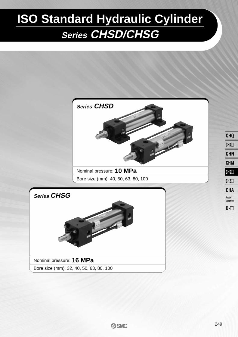
Series CHSD/CHSGISO Standard Hydraulic Cylinder
Series CHSG
Nominal pressure: 16 MPaBore size (mm): 32, 40, 50, 63, 80, 100
Series CHSD
Nominal pressure: 10 MPaBore size (mm): 40, 50, 63, 80, 100
249
CHQ
CHK�
CHN
CHM
CHS�
CH2�
CHA
D-�
RelatedEquipment
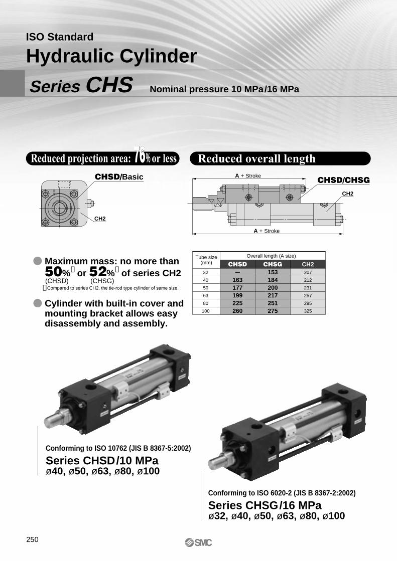
ISO Standard
Hydraulic Cylinder
Series CHS Nominal pressure 10 MPa/16 MPa
76Reduced projection area: 76% or less Reduced overall length
CHSD/Basic
CH2
� Maximum mass: no more than 50%∗ or 52%∗ of series CH2
� Cylinder with built-in cover and mounting bracket allows easy disassembly and assembly.
∗Compared to series CH2, the tie-rod type cylinder of same size.(CHSD) (CHSG)
A + Stroke
A + StrokeCHSD/CHSG
CH2
Conforming to ISO 10762 (JIS B 8367-5:2002)
Series CHSD/10 MPaø40, ø50, ø63, ø80, ø100
Conforming to ISO 6020-2 (JIS B 8367-2:2002)
Series CHSG/16 MPaø32, ø40, ø50, ø63, ø80, ø100
32
40
50
63
80
100
-163177199225260
153184200217251275
207
212
231
257
295
325
CHSD CHSG CH2Tube size
(mm)Overall length (A size)
250
CH D SD B 40
∗ Select an applicable auto switch model from the table below.
Magnet for autoswitch Number of auto
switchesSeries type
Mounting styleBore sizeB
LAFYFZCBTA
Basic
Transaxial foot style
Rod rectangular flange style
Head rectangular flange style
Double clevis
Rod trunnion
Nil
Sn
2 pcs.
1 pc.
"n" pcs.
Auto switchNil Without auto switch
Nil
DWithout
Built-inSymbol
DNominal pressure
10 MPa
40506380100
40 mm
50 mm
63 mm
80 mm
100 mm
Port thread typeNil
TNTF
Rc
NPT
GF Cylinder suffixNil
ANil
NRH
Without rod end nut
With rod end nut
With cushion on both sides
Without cushion
With front bumper
With rear bumper
Rod endnut
100 M9BW
Symbol
A
B
C
D
E
Position
Nil
Port ontop,
cushionvalve onthe right
Port ontop,
cushionvalve onthe left
Port ontop,
cushionvalvedown
Port onthe right,cushionvalve on
top
Port onthe right,cushionvalve on the left
Port onthe right,cushionvalvedown
Port and cushion valvelocation viewed fromthe side of piston rod
end thread
Port position
Note 1) Refer to table 1 for manufacturability.Note 2) Diagrams illustrate the view from the rod on the left side of the cylinder dimensions. Note 3) For mounting types FY, FZ, or TA, indicate port position with the symbol B.
Piping port Cushion valve
Table 1 Manufacturability Check List by Mounting Type and Port Position
Stroke
Built-in Magnet Cylinder Model If a built-in magnet cylinder without auto switch is required, there is no need to enter the symbol for the auto switch.(Example) CHDSDB50-100
∗ Lead wire length symbols: 0.5 m ······ Nil (Example) M9NW 1 m ······ M (Example) M9NWM 3 m ······ L (Example) M9NWL 5 m ······ Z (Example) M9NWZ
∗∗ Water resistant type auto switches can be mounted on the above models, but in such case SMC cannot guarantee water resistance. Consult with SMC regarding water resistant types with the above model numbers.
SpecialfunctionType
Elec-tricalentry
Grommet
Grommet
Wiring(output)
3-wire (NPN equiv.)
Load voltage
100 V100 V or less100 V, 200 V200 V or less
ACDC
Lead wire length (m)
RelayPLC
Applicableload
Applicable Auto Switches: Refer to pages 347 to 406 for further details on each auto switch.
5 V
12 V
100 V, 200 V
5 V, 12 V
12 V
5 V, 12 V
12 V
5 V, 12 V
12 V5 V, 12 V
24 V
Yes
NoYesNoYes
Diagnostic output (2-color display)
Diagnostic output (2-color display)
Yes
3-wire (NPN)3-wire (PNP)
2-wire
3-wire (NPN)3-wire (PNP)
2-wire3-wire (NPN)3-wire (PNP)
2-wire4-wire (NPN)
24 V
24 V
ICcircuit
ICcircuit Relay
PLC
Auto switchmodel
Z76Z73Z80A54∗
A64∗
A59W∗
M9NM9PM9BJ51
M9NWM9PWM9BWM9NA∗∗
M9PA∗∗
M9BA∗∗
F59F
Pre-wiredcon-
nector
ICcircuit
IC circuit
IC circuit
IC circuit
0.5(Nil)
3(L)
1(M)
5(Z)
Ree
d s
wit
chS
olid
sta
te s
wit
ch
Indica
tor lig
ht
Refer to the standard stroke table on page 252.
Nil
ABCDE
Portposition
Mountingbracket B LA CB TA
FYFZ
Note)
Note)
Note)
: Standard product : Made to order : Not available due to size limitation.Note) Each of C, D, E is same as the Nil, A,
B just turned.
Presenceof cusion
Note) When more than one symbol is to be specified, indicate them in alphabetical order.
Diagnostic indication(2-color display)
Water resistant(2-color indicator)
2-wire
∗ Solid state auto switches marked with “ ” are produced upon receipt of order.
∗ D-A5/A6/A59W can not be mounted to ø40, 50.
∗ Besides the models in the above table, there are some other auto switches that are applicable. For more information, refer to page 257.
∗ For details about auto switches with pre-wired connector, refer to pages 389 and 390.∗ D-M9, M9W, M9AL, Z7, Z80 auto switches are shipped together, (not assembled). (Only auto switch mounting brack-
ets are packed assembled.)
ISO Standard Hydraulic Cylinder
ø40, ø50, ø63, ø80, ø100Series CHSD
10 MPa
251
CHQ
CHK
CHN
CHM
CHS
CH2
CHA
D-
RelatedEquipment
How to Order
40 50 63 80100
Standard stroke (mm)
25 to 800
25 to 800
25 to 800
25 to 800
25 to 1000
40 50 63 80 100
40
50
63
80
100
22
28
36
45
56
1256
876
1963
1347
3117
2099
5026
3436
7853
5390
Theoretical output (N) = Pressure (MPa) x Piston area (mm2)
Mass
Basic mass (0 stroke)
Additional mass per 10 strokes
Basic
Transaxial foot
Rod flange
Head flange
Double clevis
Rod trunnion
12560
8760
19630
13470
31170
20990
50260
34360
78530
53900
107
8792
6132
13741
9429
21819
14693
35182
24052
57971
37730
3.5
4396
3066
6871
4715
10910
7346
17591
12026
27486
18865
B
LA
FY
FZ
CB
TA
402.10
2.40
2.60
2.50
2.30
2.10
0.06
503.20
3.60
3.80
3.80
3.50
3.40
0.09
635.10
5.50
5.90
6.00
6.10
5.40
0.13
808.90
9.70
10.1
10.0
9.90
9.40
0.21
10014.5
16.0
16.0
16.4
16.2
15.5
0.32
Unit: kg
JIS Symbol
Bore size (mm)
Specifications
Note) Refer to page 134 for definitions of terms related to pressure.
Theoretical OutputUnit: N
OUT IN
Action
Fluid
Nominal pressure
Maximum allowable pressure
Proof pressure
Piston speed
Cushion
Thread tolerance
With pressure at front side
With pressure at rear side
Without magnet
Built-in magnet
100 mm or less
101 to 250 mm
251 to 630 mm
631 to 1000 mm
Double Acting: Single Rod
General mineral hydraulic fluid
10 MPa
12 MPa
15 MPa
0.25 MPa
0.15 MPa
-10 to 80°C-10 to 60°C
8 to 300 mm/s
Cushion seal
JIS 6 g/6 H
0 to +0.8 mm
0 to +1.0 mm
0 to +1.25 mm
0 to +1.4 mm
Minimum operating pressure
Ambient and fluid temperature
Stroke length tolerance
Standard Stroke
Bore size (mm)
Bore size(mm)
Rod size(mm)
Operatingdirection
Piston area(mm2)
Operating pressure (MPa)
OUT
IN
OUT
IN
OUT
IN
OUT
IN
OUT
IN
Bore size (mm)
Series CHSD
252
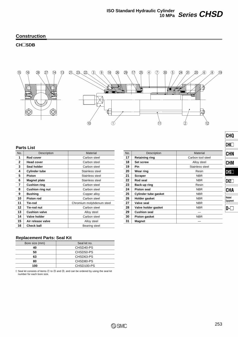
Construction
CH�SDB
q w !2!1
t @4 #1 @0 y i !9#0ur@5!7@9@6!8oe@2@3@1!3!4@7@8!6!5
!0
Series CHSDISO Standard Hydraulic Cylinder10 MPa
253
Rod cover
Head cover
Seal holder
Cylinder tube
Piston
Magnet plate
Cushion ring
Cushion ring nut
Bushing
Piston rod
Tie-rod
Tie-rod nut
Cushion valve
Valve holder
Air release valve
Check ball
No.
12345678910111213141516
Material
Carbon steel
Carbon steel
Carbon steel
Stainless steel
Stainless steel
Stainless steel
Carbon steel
Carbon steel
Copper alloy
Carbon steel
Chromium molybdenum steel
Carbon steel
Alloy steel
Carbon steel
Alloy steel
Bearing steel
Parts List
Bore size (mm)
40506380100
Seal kit no.
CHSD40-PSCHSD50-PSCHSD63-PSCHSD80-PSCHSD100-PS
Replacement Parts: Seal Kit
Retaining ring
Set screw
Pin
Wear ring
Scraper
Rod seal
Back-up ring
Piston seal
Cylinder tube gasket
Holder gasket
Valve seal
Valve holder gasket
Cushion seal
Piston gasket
Magnet
No.
171819202122232425262728293031
Material
Carbon tool steel
Alloy steel
Stainless steel
Resin
NBR
NBR
Resin
NBR
NBR
NBR
NBR
NBR
—
NBR
—
∗ Seal kit consists of items @1 to @5 and @9, and can be ordered by using the seal kit number for each bore size.
DescriptionDescription
CHQ
CHK�
CHN
CHM
CHS�
CH2�
CHA
D-�
RelatedEquipment
40
50
63
80
100
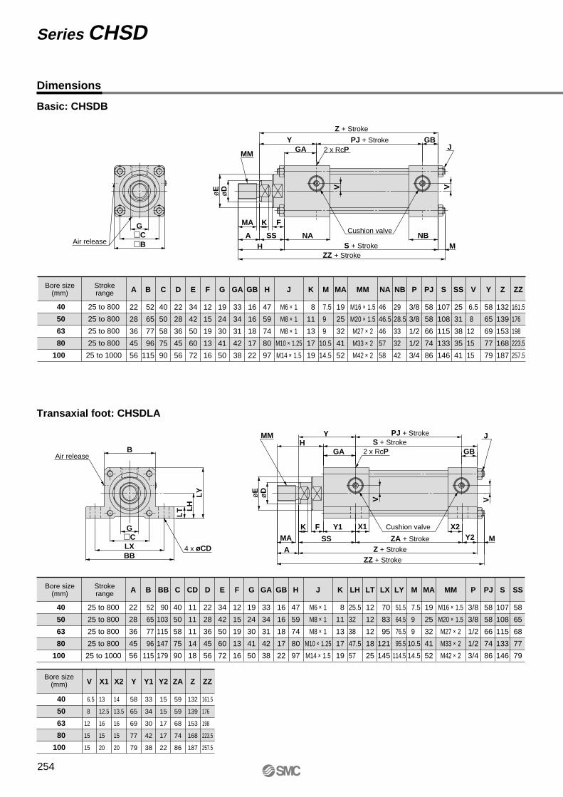
Dimensions
Basic: CHSDB
Transaxial foot: CHSDLA
G
PJ + StrokeY
X1
MY2
Z + Stroke
ZA + StrokeSS
X2
S + StrokeH
LY
LH
LT
B
BBLX
Y1�C
VVøE
øD
MA
A
K F
ZZ + Stroke
GBGA
4 x øCD
Air release
JMM
2 x RcP
GSS
Z + Stroke
PJ + StrokeY
M�B�C
øE
øD VV
GBGA
ZZ + Stroke
NBS + StrokeH
MA
A
K F
NACushion valve
J
Air release
MM 2 x RcP
Z
132
139
153
168
187
Y2
15
15
17
17
22
Y1
33
34
30
42
38
ZA
59
59
68
74
86
Y
58
65
69
77
79
ZZ
161.5
176
198
223.5
257.5
V
6.5
8
12
15
15
X1
13
12.5
16
15
20
X2
14
13.5
16
15
20
Cushion valve
Bore size(mm)
Z
132
139
153
168
187
Y
58
65
69
77
79
SS
25
31
38
35
41
PJ
58
58
66
74
86
V
6.5
8
12
15
15
E
34
42
50
60
72
ZZ
161.5
176
198
223.5
257.5
H
47
59
74
80
97
K
8
11
13
17
19
G
19
24
30
41
50
D
22
28
36
45
56
MA
19
25
32
41
52
A
22
28
36
45
56
MM
M16 × 1.5
M20 × 1.5
M27 × 2
M33 × 2
M42 × 2
S
107
108
115
133
146
P
3/8
3/8
1/2
1/2
3/4
NB
29
28.5
33
32
42
NA
46
46.5
46
57
58
MJ
M6 × 1
M8 × 1
M8 × 1
M10 × 1.25
M14 × 1.5
GB
16
16
18
17
22
GA
33
34
31
42
38
F
12
15
19
13
16
C
40
50
58
75
90
B
52
65
77
96
115
25 to 800
25 to 800
25 to 800
25 to 800
25 to 1000
40
50
63
80
100
7.5
9
9
10.5
14.5
Strokerange
Bore size(mm)
Series CHSD
254
PJ
58
58
66
74
86
SS
58
65
68
77
79
LY
51.5
64.5
76.5
95.5
114.5
LH
25.5
32
38
47.5
57
LT
12
12
12
18
25
LX
70
83
95
121
145
BB
90
103
115
147
179
CD
11
11
11
14
18
E
34
42
50
60
72
H
47
59
74
80
97
K
8
11
13
17
19
G
19
24
30
41
50
D
22
28
36
45
56
MA
19
25
32
41
52
A
22
28
36
45
56
MM
M16 × 1.5
M20 × 1.5
M27 × 2
M33 × 2
M42 × 2
S
107
108
115
133
146
P
3/8
3/8
1/2
1/2
3/4
MJ
M6 × 1
M8 × 1
M8 × 1
M10 × 1.25
M14 × 1.5
GB
16
16
18
17
22
GA
33
34
31
42
38
F
12
15
19
13
16
C
40
50
58
75
90
B
52
65
77
96
115
Strokerange
Bore size(mm)
7.5
9
9
10.5
14.5
40
50
63
80
100
25 to 800
25 to 800
25 to 800
25 to 800
25 to 1000
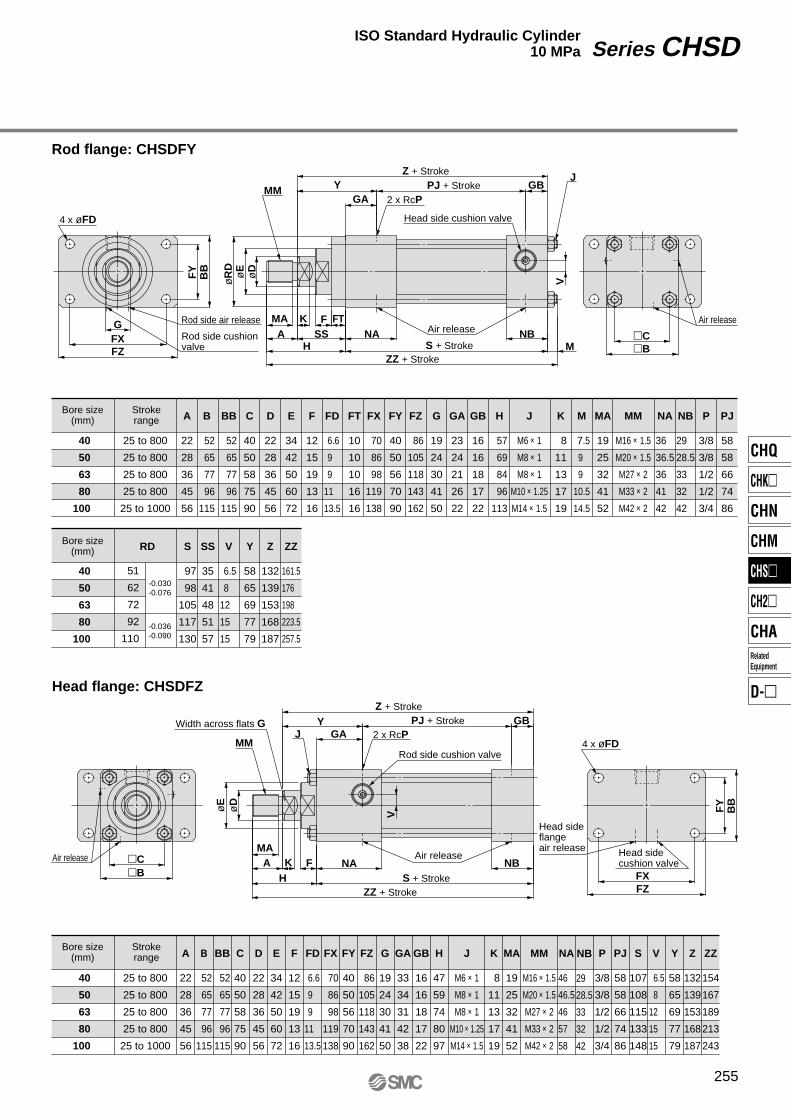
Rod flange: CHSDFYZ + Stroke
PJ + StrokeY
G
HSS
GA
�B�C
BB
FY
FZFX
øR
D
FTNA
øE
øD
MAA
K FNB
M
V
GB
Head side cushion valve4 x øFD
JMM
2 x RcP
Air release
Air release
Y
øE
øD
V
GBGA
NBH
MAA K F NA
FY
BB
FZFX�B
�C
JMM
2 x RcPWidth across flats G
4 x øFD
Rod side cushion valve
Rod side air release
S + StrokeZZ + Stroke
Air release
25 to 800
25 to 800
25 to 800
25 to 800
25 to 1000
40
50
63
80
100
51
62
72
92
110
40
50
63
80
100
Head flange: CHSDFZ
ZZ
161.5
176
198
223.5
257.5
Y
58
65
69
77
79
NB
29
28.5
33
32
42
SS
35
41
48
51
57-0.036-0.090
-0.030-0.076
FT
10
10
10
16
16
V
6.5
8
12
15
15
Z
132
139
153
168
187
H
57
69
84
96
113
K
8
11
13
17
19
MA
19
25
32
41
52
MM
M16 × 1.5
M20 × 1.5
M27 × 2
M33 × 2
M42 × 2
S
97
98
105
117
130
P
3/8
3/8
1/2
1/2
3/4
PJ
58
58
66
74
86
NA
36
36.5
36
41
42
M
7.5
9
9
10.5
14.5
J
M6 × 1
M8 × 1
M8 × 1
M10 × 1.25
M14 × 1.5
GB
16
16
18
17
22
GA
23
24
21
26
22
FZ
86
105
118
143
162
FY
40
50
56
70
90
FX
70
86
98
119
138
FD
6.6
9
9
11
13.5
BB
52
65
77
96
115
E
34
42
50
60
72
G
19
24
30
41
50
D
22
28
36
45
56
A
22
28
36
45
56
F
12
15
19
13
16
C
40
50
58
75
90
B
52
65
77
96
115
Strokerange
Bore size(mm)
Bore size(mm) RD
Z + StrokePJ + Stroke
ZZ + StrokeS + Stroke
Rod side cushion valve
Air release Head side cushion valve
Head sideflange air release
25 to 800
25 to 800
25 to 800
25 to 800
25 to 1000
40
50
63
80
100
PJ
58
58
66
74
86
H
47
59
74
80
97
K
8
11
13
17
19
MA
19
25
32
41
52
MM
M16 × 1.5
M20 × 1.5
M27 × 2
M33 × 2
M42 × 2
P
3/8
3/8
1/2
1/2
3/4
NB
29
28.5
33
32
42
NA
46
46.5
46
57
58
J
M6 × 1
M8 × 1
M8 × 1
M10 × 1.25
M14 × 1.5
GB
16
16
18
17
22
GA
33
34
31
42
38
FZ
86
105
118
143
162
FY
40
50
56
70
90
FX
70
86
98
119
138
FD
6.6
9
9
11
13.5
BB
52
65
77
96
115
E
34
42
50
60
72
G
19
24
30
41
50
D
22
28
36
45
56
A
22
28
36
45
56
F
12
15
19
13
16
C
40
50
58
75
90
B
52
65
77
96
115
Z
132
139
153
168
187
S
107
108
115
133
148
ZZ
154
167
189
213
243
V
6.5
8
12
15
15
Y
58
65
69
77
79
Strokerange
Bore size(mm)
Series CHSDISO Standard Hydraulic Cylinder10 MPa
255
CHQ
CHK�
CHN
CHM
CHS�
CH2�
CHA
D-�
RelatedEquipment
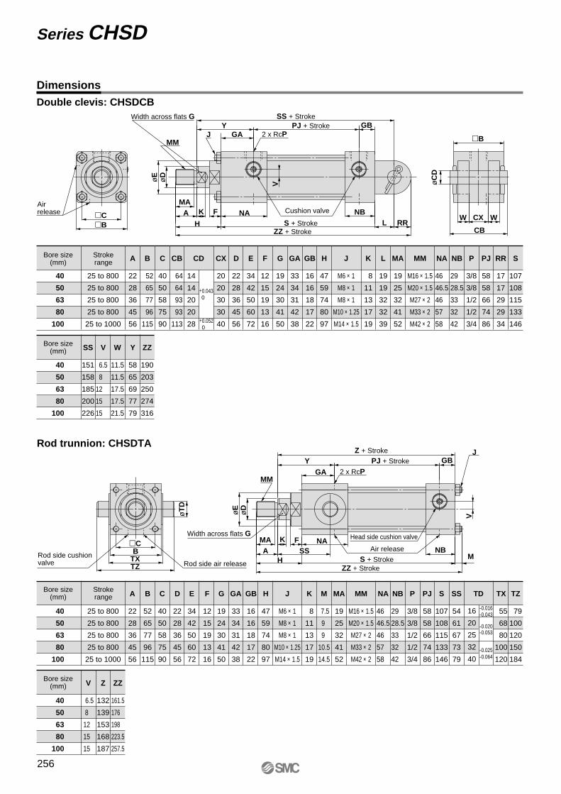
DimensionsDouble clevis: CHSDCB
V
WW
øE
GBGA
MA
H
NBNAK F
øC
D
�B
CX
CBRRL
A
Y
øD
�B�C
2 x RcP
Width across flats G
JMM
Air release
Y
øT
D
TZTX
SSFK
AMA�C
B
V
MNB
NA
H
øD
øE
GB
GA
Rod side air releaseRod side cushion valve
Width across flats G
MM
J
2 x RcP
SS + Stroke
S + StrokeZZ + Stroke
PJ + Stroke
Cushion valve
40
50
63
80
100
25 to 800
25 to 800
25 to 800
25 to 800
25 to 1000
40
50
63
80
100
Rod trunnion: CHSDTA
Y
58
65
69
77
79
V
6.5
8
12
15
15
PJ
58
58
66
74
86
E
34
42
50
60
72
CB
64
64
93
93
113 +0.052 0
+0.043 0
CX
20
20
30
30
40
C
40
50
58
75
90
SS
151
158
185
200
226
W
11.5
11.5
17.5
17.5
21.5
ZZ
190
203
250
274
316
H
47
59
74
80
97
K
8
11
13
17
19
MA
19
25
32
41
52
MM
M16 × 1.5
M20 × 1.5
M27 × 2
M33 × 2
M42 × 2
P
3/8
3/8
1/2
1/2
3/4
NB
29
28.5
33
32
42
NA
46
46.5
46
57
58
L
19
19
32
32
39
J
M6 × 1
M8 × 1
M8 × 1
M10 × 1.25
M14 × 1.5
GB
16
16
18
17
22
GA
33
34
31
42
38
G
19
24
30
41
50
D
22
28
36
45
56
A
22
28
36
45
56
F
12
15
19
13
16
CD
14
14
20
20
28
B
52
65
77
96
115
RR
17
17
29
29
34
S
107
108
115
133
146
Strokerange
Bore size(mm)
Bore size(mm)
Z + Stroke
PJ + Stroke
S + StrokeZZ + Stroke
Head side cushion valve
Air release
40
50
63
80
100
25 to 800
25 to 800
25 to 800
25 to 800
25 to 1000
40
50
63
80
100
ZZ
161.5
176
198
223.5
257.5
PJ
58
58
66
74
86
V
6.5
8
12
15
15
E
34
42
50
60
72
Z
132
139
153
168
187
H
47
59
74
80
97
K
8
11
13
17
19
G
19
24
30
41
50
D
22
28
36
45
56
MA
19
25
32
41
52
A
22
28
36
45
56
MM
M16 × 1.5
M20 × 1.5
M27 × 2
M33 × 2
M42 × 2
P
3/8
3/8
1/2
1/2
3/4
NB
29
28.5
33
32
42
NA
46
46.5
46
57
58
M
7.5
9
9
10.5
14.5
J
M6 × 1
M8 × 1
M8 × 1
M10 × 1.25
M14 × 1.5
GB
16
16
18
17
22
GA
33
34
31
42
38
F
12
15
19
13
16
C
40
50
58
75
90
B
52
65
77
96
115
S
107
108
115
133
146
SS
54
61
67
73
79-0.025-0.064
-0.020-0.053
-0.016-0.04316
20
25
32
40
TX
55
68
80
100
120
TZ
79
100
120
150
184
Strokerange
Bore size(mm)
Bore size(mm)
TD
Series CHSD
256
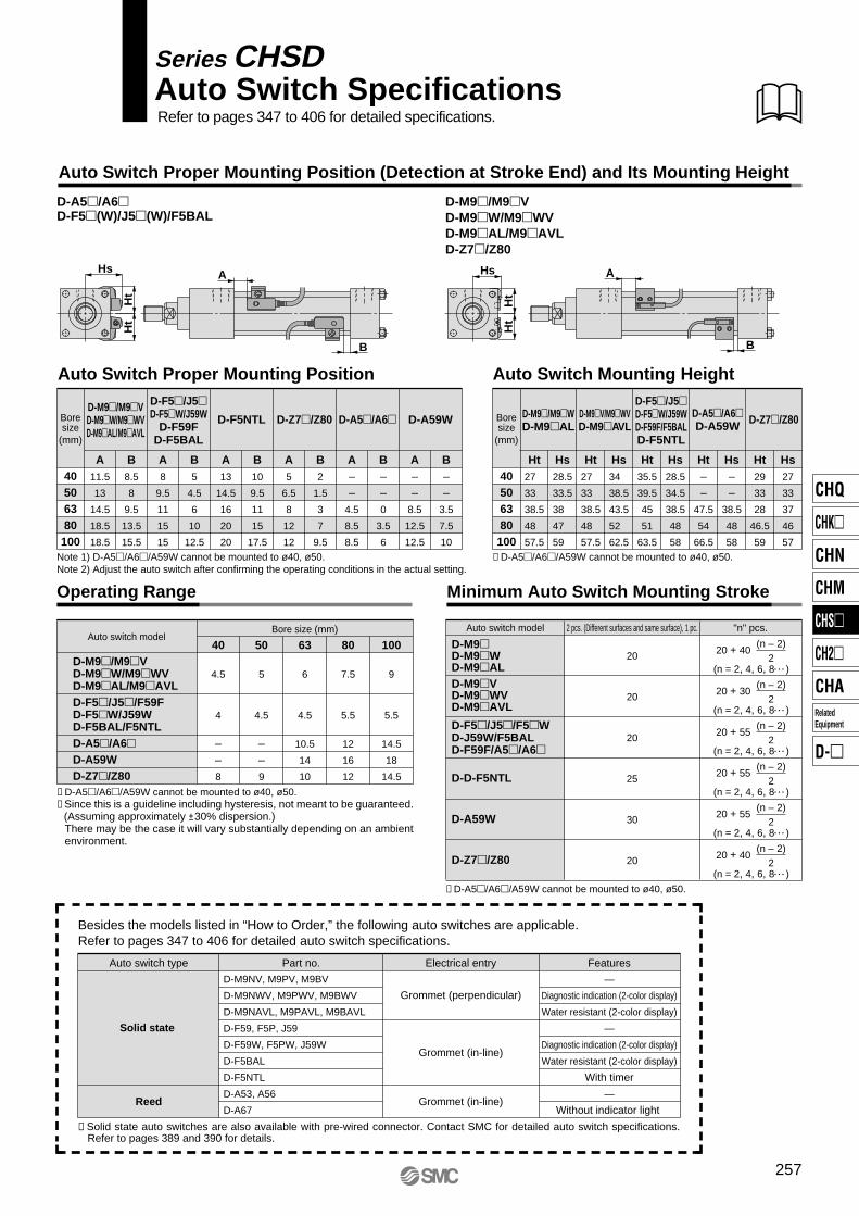
Auto Switch Proper Mounting Position (Detection at Stroke End) and Its Mounting Height
Minimum Auto Switch Mounting Stroke
Auto Switch Proper Mounting Position
Ht
Ht
Hs
B
A
D-A5�/A6�D-F5�(W)/J5�(W)/F5BAL
Ht
Ht
Hs
B
A
D-M9�/M9�VD-M9�W/M9�WVD-M9�AL/M9�AVLD-Z7�/Z80
Boresize
(mm)
40506380100
Auto switch model 2 pcs. (Different surfaces and same surface), 1 pc. "n" pcs.
D-M9�D-M9�WD-M9�ALD-M9�VD-M9�WVD-M9�AVL
D-F5�/J5�/F5�WD-J59W/F5BALD-F59F/A5�/A6�
D-D-F5NTL
D-A59W
D-Z7�/Z80
Auto Switch Mounting Height
20
20
20
25
30
20
(n = 2, 4, 6, 8• • • )
(n – 2)2
D-A59WD-F5NTLD-M9�/M9�VD-M9�W/M9�WVD-M9�AL/M9�AVL
D-F5�/J5�D-F5�W/J59W
D-F59FD-F5BAL
D-Z7�/Z80 D-A5�/A6�
A––
8.5
12.5
12.5
B––
3.5
7.5
10
A––
4.5
8.5
8.5
B––0
3.5
6
A5
6.5
8
12
12
B2
1.5
3
7
9.5
A13
14.5
16
20
20
B10
9.5
11
15
17.5
A8
9.5
11
15
15
B5
4.5
6
10
12.5
A11.5
13
14.5
18.5
18.5
B8.5
8
9.5
13.5
15.5
Boresize
(mm)
40506380100
D-F5�/J5�D-F5�W/J59WD-F59F/F5BALD-F5NTL
Ht––
47.5
54
66.5
Ht29
33
28
46.5
59
Hs––
38.5
48
58
Hs27
33
37
46
57
Ht35.5
39.5
45
51
63.5
Hs28.5
34.5
38.5
48
58
Ht27
33
38.5
48
57.5
Hs34
38.5
43.5
52
62.5
Ht27
33
38.5
48
57.5
Hs28.5
33.5
38
47
59
D-M9�V/M9�WVD-M9�AVL
D-A5�/A6�D-A59W D-Z7�/Z80D-M9�/M9�W
D-M9�AL
Operating Range
D-M9�/M9�VD-M9�W/M9�WVD-M9�AL/M9�AVLD-F5�/J5�/F59FD-F5�W/J59WD-F5BAL/F5NTLD-A5�/A6� D-A59WD-Z7�/Z80
40
4.5
4
––8
50
5
4.5
––9
63
6
4.5
10.5
14
10
Bore size (mm)
80
7.5
5.5
12
16
12
100
9
5.5
14.5
18
14.5
Auto switch model
(n = 2, 4, 6, 8• • • )
(n – 2)2
(n = 2, 4, 6, 8• • • )
(n – 2)2
(n = 2, 4, 6, 8• • • )
(n – 2)2
(n = 2, 4, 6, 8• • • )
(n – 2)2
20 + 40
20 + 30
20 + 55
20 + 55
20 + 55
20 + 40
(n = 2, 4, 6, 8• • • )
(n – 2)2
Auto Switch SpecificationsSeries CHSD
Refer to pages 347 to 406 for detailed specifications.
Note 1) D-A5�/A6�/A59W cannot be mounted to ø40, ø50. Note 2) Adjust the auto switch after confirming the operating conditions in the actual setting.
∗ D-A5�/A6�/A59W cannot be mounted to ø40, ø50.∗ Since this is a guideline including hysteresis, not meant to be guaranteed. (Assuming approximately ±30% dispersion.)
There may be the case it will vary substantially depending on an ambientenvironment.
∗ D-A5�/A6�/A59W cannot be mounted to ø40, ø50.
∗ D-A5�/A6�/A59W cannot be mounted to ø40, ø50.
∗ Solid state auto switches are also available with pre-wired connector. Contact SMC for detailed auto switch specifications. Refer to pages 389 and 390 for details.
Besides the models listed in “How to Order,” the following auto switches are applicable.Refer to pages 347 to 406 for detailed auto switch specifications.
Auto switch type Part no. FeaturesElectrical entry
D-M9NV, M9PV, M9BV
D-M9NWV, M9PWV, M9BWV
D-M9NAVL, M9PAVL, M9BAVL
D-F59, F5P, J59
D-F59W, F5PW, J59W
D-F5BAL
D-F5NTL
D-A53, A56
D-A67
—
Diagnostic indication (2-color display)
Water resistant (2-color display)
—
Diagnostic indication (2-color display)
Water resistant (2-color display)
With timer
—
Without indicator light
Solid state
Reed
Grommet (perpendicular)
Grommet (in-line)
Grommet (in-line)
257
CHQ
CHK�
CHN
CHM
CHS�
CH2�
CHA
D-�
RelatedEquipment
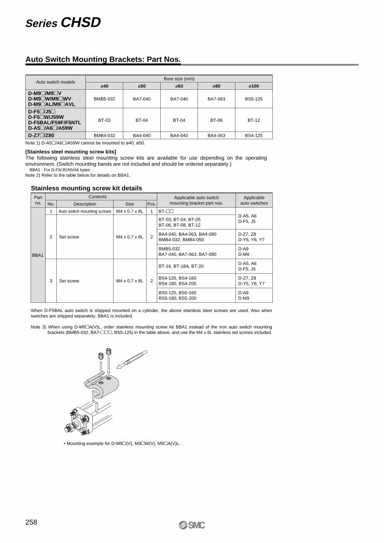
Auto Switch Mounting Brackets: Part Nos.
[Stainless steel mounting screw kits]The following stainless steel mounting screw kits are available for use depending on the operating environment. (Switch mounting bands are not included and should be ordered separately.)
BBA1 : For D-F5/J5/A5/A6 typesNote 2) Refer to the table below for details on BBA1.
Auto switch modelsBore size (mm)
D-M9�/M9�VD-M9�W/M9�WVD-M9�AL/M9�AVLD-F5�/J5�D-F5�W/J59WD-F5BAL/F59F/F5NTLD-A5�/A6�/A59WD-Z7�/Z80
ø40
BMB5-032
BT-03
BMB4-032
ø50
BA7-040
BT-04
BA4-040
ø63
BA7-040
BT-04
BA4-040
ø80 ø100
BA7-063
BT-06
BA4-063
BS5-125
BT-12
BS4-125
Note 1) D-A5�/A6�/A59W cannot be mounted to ø40, ø50.
When D-F5BAL auto switch is shipped mounted on a cylinder, the above stainless steel screws are used. Also when switches are shipped separately, BBA1 is included.
Note 3) When using D-M9�A(V)L, order stainless mounting screw kit BBA1 instead of the iron auto switch mounting brackets (BMB5-032, BA7-���, BS5-125) in the table above, and use the M4 x 6L stainless set screws included.
• Mounting example for D-M9�(V), M9�W(V), M9�A(V)L.
Partno.
Contents
BBA1
Description
Auto switch mounting screws
Set screw
Set screw
Size
M4 x 0.7 x 8L
M4 x 0.7 x 6L
M4 x 0.7 x 8L
Pcs.No.
11
2
3
2
2
Applicable auto switchmounting bracket part nos.
Applicableauto switches
BT-��
BT-03, BT-04, BT-05BT-06, BT-08, BT-12
BT-16, BT-18A, BT-20
BA4-040, BA4-063, BA4-080BMB4-032, BMB4-050
BS4-125, BS4-160BS4-180, BS4-200
BS5-125, BS5-160BS5-180, BS5-200
BMB5-032BA7-040, BA7-063, BA7-080
D-A5, A6D-F5, J5
D-A9D-M9
D-Z7, Z8D-Y5, Y6, Y7
D-A5, A6D-F5, J5
D-A9D-M9
D-Z7, Z8D-Y5, Y6, Y7
Stainless mounting screw kit details
Series CHSD
258
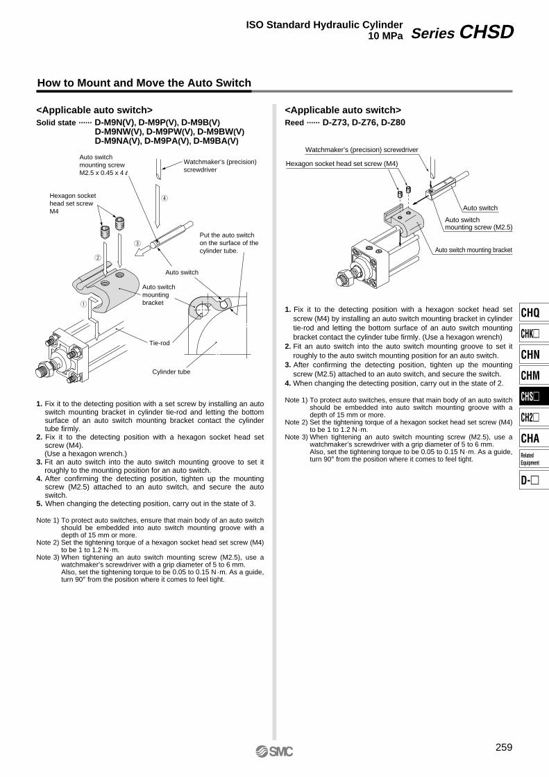
How to Mount and Move the Auto Switch
Put the auto switch on the surface of the cylinder tube.
Cylinder tube
Tie-rod
Watchmaker’s (precision) screwdriver
Auto switchmounting bracket
Hexagon socket head set screwM4
Auto switch
Auto switchmounting screwM2.5 x 0.45 x 4 l
r
e
w
q
1. Fix it to the detecting position with a set screw by installing an auto switch mounting bracket in cylinder tie-rod and letting the bottom surface of an auto switch mounting bracket contact the cylinder tube firmly.
2. Fix it to the detecting position with a hexagon socket head set screw (M4).
(Use a hexagon wrench.)3. Fit an auto switch into the auto switch mounting groove to set it
roughly to the mounting position for an auto switch.4. After confirming the detecting position, tighten up the mounting
screw (M2.5) attached to an auto switch, and secure the auto switch.
5. When changing the detecting position, carry out in the state of 3.
Note 1) To protect auto switches, ensure that main body of an auto switch should be embedded into auto switch mounting groove with a depth of 15 mm or more.
Note 2) Set the tightening torque of a hexagon socket head set screw (M4) to be 1 to 1.2 N·m.
Note 3) When tightening an auto switch mounting screw (M2.5), use a watchmaker’s screwdriver with a grip diameter of 5 to 6 mm.Also, set the tightening torque to be 0.05 to 0.15 N·m. As a guide, turn 90° from the position where it comes to feel tight.
<Applicable auto switch>Solid state ······ D-M9N(V), D-M9P(V), D-M9B(V) D-M9NW(V), D-M9PW(V), D-M9BW(V) D-M9NA(V), D-M9PA(V), D-M9BA(V)
1. Fix it to the detecting position with a hexagon socket head set screw (M4) by installing an auto switch mounting bracket in cylinder tie-rod and letting the bottom surface of an auto switch mounting bracket contact the cylinder tube firmly. (Use a hexagon wrench)
2. Fit an auto switch into the auto switch mounting groove to set it roughly to the auto switch mounting position for an auto switch.
3. After confirming the detecting position, tighten up the mounting screw (M2.5) attached to an auto switch, and secure the switch.
4. When changing the detecting position, carry out in the state of 2.
Note 1) To protect auto switches, ensure that main body of an auto switch should be embedded into auto switch mounting groove with a depth of 15 mm or more.
Note 2) Set the tightening torque of a hexagon socket head set screw (M4) to be 1 to 1.2 N·m.
Note 3) When tightening an auto switch mounting screw (M2.5), use a watchmaker’s screwdriver with a grip diameter of 5 to 6 mm.Also, set the tightening torque to be 0.05 to 0.15 N·m. As a guide, turn 90° from the position where it comes to feel tight.
Hexagon socket head set screw (M4)
Auto switch mounting bracket
Auto switch
Watchmaker’s (precision) screwdriver
Auto switchmounting screw (M2.5)
<Applicable auto switch>Reed ······ D-Z73, D-Z76, D-Z80
259
Series CHSDISO Standard Hydraulic Cylinder10 MPa
CHQ
CHK�
CHN
CHM
CHS�
CH2�
CHA
D-�
RelatedEquipment
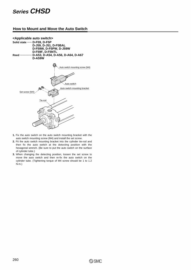
How to Mount and Move the Auto Switch
1. Fix the auto switch on the auto switch mounting bracket with the auto switch mounting screw (M4) and install the set screw.
2. Fit the auto switch mounting bracket into the cylinder tie-rod and then fix the auto switch at the detecting position with the hexagonal wrench. (Be sure to put the auto switch on the surface of cylinder tube.)
3. When changing the detecting position, loosen the set screw to move the auto switch and then re-fix the auto switch on the cylinder tube. (Tightening torque of M4 screw should be 1 to 1.2 N·m.)
<Applicable auto switch>Solid state ······ D-F59, D-F5P
D-J59, D-J51, D-F5BALD-F59W, D-F5PW, D-J59WD-F59F, D-F5NTL
Reed ··············· D-A53, D-A54, D-A56, D-A64, D-A67D-A59W
Auto switch mounting screw (M4)
Auto switch
Auto switch mounting bracket
Set screw (M4)
Tie-rod
Series CHSD
260
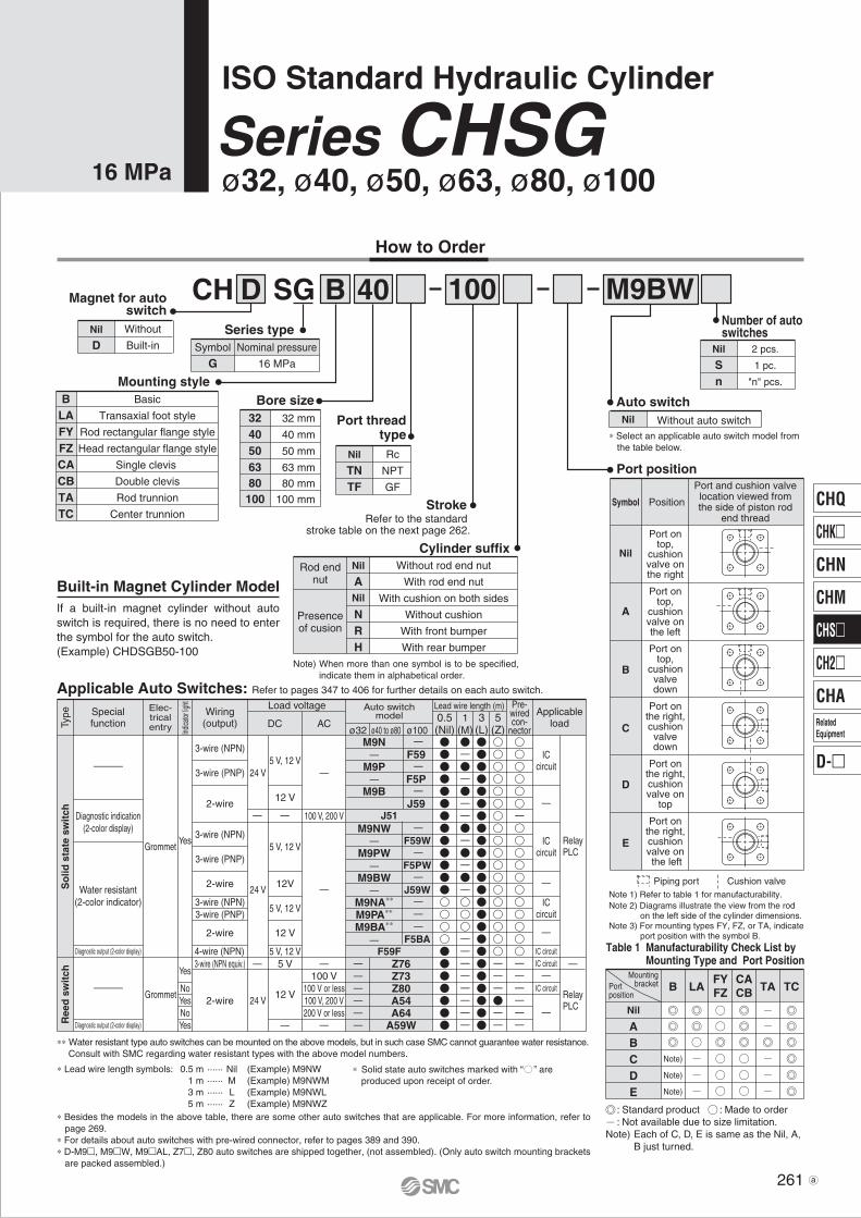
CH D SG B 40
∗ Select an applicable auto switch model from the table below.
Magnet for autoswitch
Series type
Mounting styleBore sizeB
LAFYFZCACBTATC
Basic
Transaxial foot style
Rod rectangular flange style
Head rectangular flange style
Single clevis
Double clevis
Rod trunnion
Center trunnion
Number of auto switches
Nil
Sn
2 pcs.
1 pc.
"n" pcs.
Auto switch
Stroke
Nil Without auto switch
Nil
DWithout
Built-in Symbol
GNominal pressure
16 MPa
3240506380100
32 mm
40 mm
50 mm
63 mm
80 mm
100 mm
Port threadtype
Nil
TNTF
Rc
NPT
GF
100 M9BW
Table 1 Manufacturability Check List by Mounting Type and Port Position
Cylinder suffixNil
ANil
NRH
Without rod end nut
With rod end nut
With cushion on both sides
Without cushion
With front bumper
With rear bumper
Rod endnut
Symbol
A
B
C
D
E
Position
Nil
Port ontop,
cushionvalve onthe right
Port ontop,
cushionvalve onthe left
Port ontop,
cushionvalvedown
Port onthe right,cushionvalve on
top
Port onthe right,cushionvalve on the left
Port onthe right,cushion
valvedown
Port and cushion valvelocation viewed fromthe side of piston rod
end thread
Port position
Note 1) Refer to table 1 for manufacturability.Note 2) Diagrams illustrate the view from the rod on the left side of the cylinder dimensions. Note 3) For mounting types FY, FZ, or TA, indicate port position with the symbol B.
Piping port Cushion valve
Built-in Magnet Cylinder Model If a built-in magnet cylinder without auto switch is required, there is no need to enter the symbol for the auto switch.(Example) CHDSGB50-100
SpecialfunctionTy
pe
Elec-tricalentry
Grommet
Grommet
Wiring(output)
3-wire (NPN equiv.)
2-wire
Load voltage
100 V100 V or less100 V, 200 V200 V or less
ACø32 ø40 to ø80 ø100
DC
Lead wire length (m)
RelayPLC
Applicableload
Applicable Auto Switches: Refer to pages 347 to 406 for further details on each auto switch.
5 V
12 V
100 V, 200 V
5 V, 12 V
12 V
5 V, 12 V
12V
5 V, 12 V
12 V
5 V, 12 V
24 V
Yes
NoYesNoYes
Diagnostic indication(2-color display)
Water resistant(2-color indicator)
Yes
24 V
24 V
RelayPLC
Auto switchmodel
Z76Z73Z80A54A64
A59W
M9N
M9P
M9B
M9NW
M9PW
M9BW
M9NA∗∗
M9PA∗∗
M9BA∗∗
F59
F5P
J59
F59W
F5PW
J59W
F5BA
J51
F59F
Pre-wiredcon-
nector0.5(Nil)
3(L)
1(M)
5(Z)
Ree
d s
wit
chS
olid
sta
te s
wit
ch
Indica
tor lig
ht
How to Order
Refer to the standard stroke table on the next page 262.
Presenceof cusion
Note) When more than one symbol is to be specified, indicate them in alphabetical order.
Nil
ABCDE
B LAFYFZ TA TC
CACB
Note)
Note)
Note)
Portposition
Mountingbracket
: Standard product : Made to order : Not available due to size limitation.Note) Each of C, D, E is same as the Nil, A,
B just turned.
3-wire (NPN)
3-wire (PNP)
2-wire
3-wire (NPN)
3-wire (PNP)
2-wire
3-wire (NPN)3-wire (PNP)
2-wire
4-wire (NPN)
ICcircuit
ICcircuit
ICcircuit
IC circuitIC circuit
IC circuit
∗ Lead wire length symbols: 0.5 m ······ Nil (Example) M9NW 1 m ······ M (Example) M9NWM 3 m ······ L (Example) M9NWL 5 m ······ Z (Example) M9NWZ
∗∗ Water resistant type auto switches can be mounted on the above models, but in such case SMC cannot guarantee water resistance. Consult with SMC regarding water resistant types with the above model numbers.
∗ Solid state auto switches marked with “ ” are produced upon receipt of order.
∗ Besides the models in the above table, there are some other auto switches that are applicable. For more information, refer to page 269.
∗ For details about auto switches with pre-wired connector, refer to pages 389 and 390.∗ D-M9, M9W, M9AL, Z7, Z80 auto switches are shipped together, (not assembled). (Only auto switch mounting brackets
are packed assembled.)
Diagnostic output (2-color display)
Diagnostic output (2-color display)
ISO Standard Hydraulic Cylinder
ø32, ø40, ø50, ø63, ø80, ø100Series CHSG
16 MPa
261
CHQ
CHK
CHN
CHM
CHS
CH2
CHA
D-
RelatedEquipment
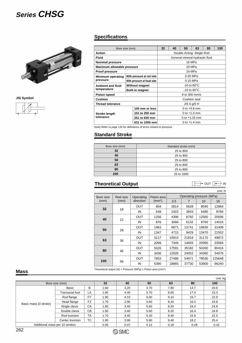
Standard Stroke
Bore size (mm)
32 40 50 63 80100
Standard stroke (mm)
25 to 800
25 to 800
25 to 800
25 to 800
25 to 800
25 to 1000
Theoretical OutputUnit: N
OUT IN
Mass
JIS Symbol
4032 50 63 80 100Bore size (mm)
Note) Refer to page 134 for definitions of terms related to pressure.
Action
Fluid
Nominal pressure
Maximum allowable pressure
Proof pressure
Piston speed
Cushion
Thread tolerance
Minimum operating pressure
Ambient and fluid temperature
Stroke length tolerance
With pressure at rod side
With pressure at head side
Without magnet
Built-in magnet
100 mm or less
101 to 250 mm
251 to 630 mm
631 to 1000 mm
Double Acting: Single Rod
General mineral hydraulic fluid
16 MPa
20 MPa
24 MPa
0.25 MPa
0.15 MPa
-10 to 80°C-10 to 60°C
8 to 300 mm/s
Cushion seal
JIS 6 g/6 H
0 to +0.8 mm
0 to +1.0 mm
0 to +1.25 mm
0 to +1.4 mm
OUT
IN
OUT
IN
OUT
IN
OUT
IN
OUT
IN
OUT
IN
32
40
50
63
80
100
18
22
28
36
45
56
804
549
1256
876
1963
1347
3117
2099
5026
3436
7853
5390
Theoretical output (N) = Pressure (MPa) x Piston area (mm2)
16
12864
8784
20096
14016
31408
21552
49872
33584
80416
54976
125648
86240
10
8040
5490
12560
8760
19630
13470
31170
20990
50260
34360
78530
53900
7
5628
3843
8792
6132
13741
9429
21819
14693
35182
24052
54971
37730
3.5
2814
1922
4396
3066
6871
4715
10910
7346
17591
12026
27486
18865
Bore size(mm)
Rod size(mm)
Operatingdirection
Piston area(mm2)
Operating pressure (MPa)
Bore size (mm)
Basic mass (0 stroke)
Additional mass per 10 strokes
Basic
Transaxial foot
Rod flange
Head flange
Single clevis
Double clevis
Rod trunnion
Center trunnion
B
LA
FY
FZ
CA
CB
TA
TC
403.20
4.00
4.10
3.90
3.40
3.40
3.40
3.90
0.07
321.60
1.80
1.90
1.70
1.60
1.60
1.70
1.90
0.05
504.70
5.70
6.00
5.60
5.60
5.60
5.20
5.80
0.12
637.80
8.65
9.10
8.20
8.20
8.20
8.40
9.40
0.18
8014.7
17.0
16.7
16.4
16.4
16.4
15.9
18.2
0.28
10020.8
23.3
22.9
24.8
24.8
24.8
22.5
25.4
0.42
Unit: kg
Series CHSG
262
Specifications

Construction
Bore size (mm)
32 40 50 63 80100
CHSG32-PSCHSG40-PSCHSG50-PSCHSG63-PSCHSG80-PSCHSG100-PS
Replacement Parts: Seal Kit
CH�SGB
!5 !6 @9 @8 !4 !3 @1 @3 @2 e o !8 @7 #0 !7 @6 r u #1 t @4 @5 #2 @0 y i !9
!0 q !1 w !2
Rod cover
Head cover
Seal holder
Cylinder tube
Piston
Magnet plate
Cushion ring
Cushion ring nut
Bushing
Piston rod
Tie-rod
Tie-rod nut
Cushion valve
Valve holder
Air release valve
Check ball
No.
12345678910111213141516
Material
Carbon steel
Carbon steel
Carbon steel
Stainless steel
Stainless steel
Stainless steel
Carbon steel
Carbon steel
Copper alloy
Carbon steel
Chromium molybdenum steel
Carbon steel
Alloy steel
Carbon steel
Alloy steel
Bearing steel
Parts ListDescription
Retaining ring
Set screw
Pin
Wear ring
Scraper
Rod seal
Back-up ring
Piston seal
Back-up ring
Cylinder tube gasket
Holder gasket
Valve seal
Valve holder gasket
Cushion seal
Piston gasket
Magnet
No.
17181920212223242526272829303132
Material
Carbon tool steel
Alloy steel
Stainless steel
Resin
NBR
NBR
Resin
NBR
Resin
NBR
NBR
NBR
NBR
—
NBR
—
Description
∗ Seal kit consists of items @1 to @6 and #0, and can be ordered by using the seal kit number for each bore size.
Seal kit no.
263
Series CHSGISO Standard Hydraulic Cylinder16 MPa
CHQ
CHK�
CHN
CHM
CHS�
CH2�
CHA
D-�
RelatedEquipment
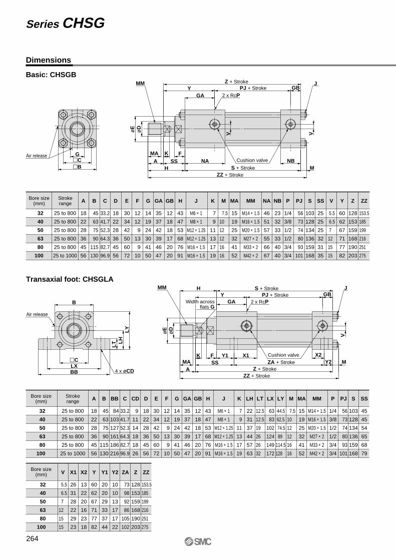
Dimensions
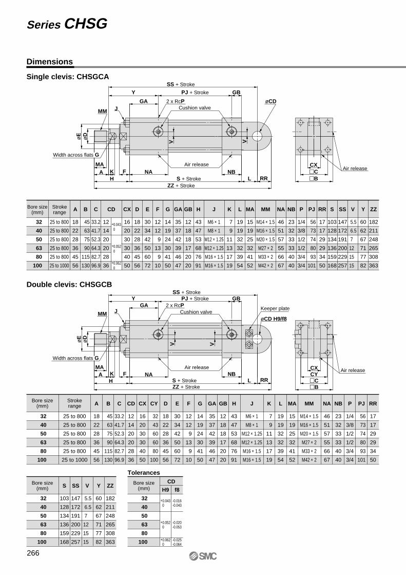
Basic: CHSGB
Transaxial foot: CHSGLA
G
Y
SS�B�C
V VøE
øD
NB
GBGA
MHNA
FKA
MA
MM J
2 x RcP
X1
Y
MY2X2
SS
H
LY
LH
LT
B
BBLX
Y1�C
VøE
øD
GBGA
FK
AMA
4 x øCD
2 x RcP
MM J
Air release
Air release
Z + StrokePJ + Stroke
ZZ + StrokeS + Stroke
Cushion valve
Z
128
153
159
168
190
203
Y
60
62
67
71
77
82
SS
25
25
25
32
31
35
PJ
56
73
74
80
93
101
V
5.5
6.5
7
12
15
15
E
30
34
42
50
60
72
ZZ
153.5
185
199
216
251
275
H
43
47
53
68
76
91
K
7
9
11
13
17
19
G
14
19
24
30
41
50
D
18
22
28
36
45
56
MA
15
19
25
32
41
52
A
18
22
28
36
45
56
MM
M14 × 1.5
M16 × 1.5
M20 × 1.5
M27 × 2
M33 × 2
M42 × 2
S
103
128
134
136
159
168
P
1/4
3/8
1/2
1/2
3/4
3/4
NB
23
32
33
33
40
40
NA
46
51
57
55
66
67
M
7.5
10
12
12
16
16
J
M6 × 1
M8 × 1
M12 × 1.25
M12 × 1.25
M16 × 1.5
M16 × 1.5
GB
12
18
18
17
20
20
GA
35
37
42
39
46
47
F
12
12
9
13
9
10
C
33.2
41.7
52.3
64.3
82.7
96.9
B
45
63
75
90
115
130
25 to 800
25 to 800
25 to 800
25 to 800
25 to 800
25 to 1000
32
40
50
63
80
100
Strokerange
Bore size(mm)
PJ + Stroke
Z + StrokeZA + Stroke
S + Stroke
ZZ + Stroke
Cushion valve
32
40
50
63
80
100
25 to 800
25 to 800
25 to 800
25 to 800
25 to 800
25 to 1000
32
40
50
63
80
100
Z
128
153
159
168
190
203
PJ
56
73
74
80
93
101
Y2
10
10
13
17
17
22
Y1
20
20
29
33
37
44
Y
60
62
67
71
77
82
ZA
73
98
92
86
105
102
X2
13
22
20
16
23
18
SS
45
45
54
65
68
79
ZZ
153.5
185
199
216
251
275
LY
44.5
62.5
74.5
89
114.5
128
LH
22
31
37
44
57
63
LT
12.5
12.5
19
26
26
32
LX
63
83
102
124
149
172
BB
84
103
127
161
186
216
CD
9
11
14
18
18
26
V
5.5
6.5
7
12
15
15
E
30
34
42
50
60
72
X1
26
31
28
22
29
23
H
43
47
53
68
76
91
K
7
9
11
13
17
19
G
14
19
24
30
41
50
D
18
22
28
36
45
56
MA
15
19
25
32
41
52
A
18
22
28
36
45
56
MM
M14 × 1.5
M16 × 1.5
M20 × 1.5
M27 × 2
M33 × 2
M42 × 2
S
103
128
134
136
159
168
P
1/4
3/8
1/2
1/2
3/4
3/4
M
7.5
10
12
12
16
16
J
M6 × 1
M8 × 1
M12 × 1.25
M12 × 1.25
M16 × 1.5
M16 × 1.5
GB
12
18
18
17
20
20
GA
35
37
42
39
46
47
F
12
12
9
13
9
10
C
33.2
41.7
52.3
64.3
82.7
96.9
B
45
63
75
90
115
130
Strokerange
Bore size(mm)
Bore size(mm)
Width acrossflats G
Series CHSG
264
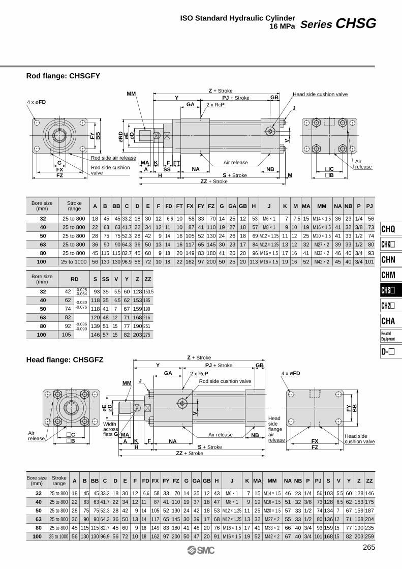
Rod flange: CHSGFY
Head flange: CHSGFZ
Y
GSS
�B�C
FT
HNA
GAB
BF
Y
FZFX
øR
D
V
øE
øD
NB
GB
M
FKA
MA
4 x øFD
MM
J2 x RcP
H�B�C
BB
FY
FZFX
V
øE
øD
NB
GBGA
Y
NAFKAMA
4 x øFD
MM
Widthacrossflats G
J2 x RcP
Rod side cushion valve
Rod side air release
Head side cushion valve
Air release
Air release
Headside flange air release
Head side cushion valve
Z + StrokePJ + Stroke
S + StrokeZZ + Stroke
Air release
25 to 800
25 to 800
25 to 800
25 to 800
25 to 800
25 to 1000
32
40
50
63
80
100
42
62
74
82
92
105
32
40
50
63
80
100
Z
128
153
159
168
190
203
NB
23
32
33
33
40
40
SS
35
35
41
48
51
57
-0.036-0.090
-0.030-0.076
-0.025-0.064
FT
10
10
16
16
20
22
V
5.5
6.5
7
12
15
15
Y
60
62
67
71
77
82
ZZ
153.5
185
199
216
251
275
H
53
57
69
84
96
113
K
7
9
11
13
17
19
MA
15
19
25
32
41
52
MM
M14 × 1.5
M16 × 1.5
M20 × 1.5
M27 × 2
M33 × 2
M42 × 2
S
93
118
118
120
139
146
P
1/4
3/8
1/2
1/2
3/4
3/4
PJ
56
73
74
80
93
101
NA
36
41
41
39
46
45
M
7.5
10
12
12
16
16
J
M6 × 1
M8 × 1
M12 × 1.25
M12 × 1.25
M16 × 1.5
M16 × 1.5
GB
12
18
18
17
20
20
GA
25
27
26
23
26
25
FZ
70
110
130
145
180
200
FY
33
41
52
65
83
97
FX
58
87
105
117
149
162
FD
6.6
11
14
14
18
18
BB
45
63
75
90
115
130
E
30
34
42
50
60
72
G
14
19
24
30
41
50
D
18
22
28
36
45
56
A
18
22
28
36
45
56
F
12
12
9
13
9
10
C
33.2
41.7
52.3
64.3
82.7
96.9
B
45
63
75
90
115
130
Strokerange
Bore size(mm)
Bore size(mm) RD
ZZ + Stroke
Z + Stroke
S + Stroke
PJ + Stroke
Air release
Rod side cushion valve
25 to 800
25 to 800
25 to 800
25 to 800
25 to 800
25 to 1000
32
40
50
63
80
100
S
103
128
134
136
159
168
PJ
56
73
74
80
93
101
H
43
47
53
68
76
91
K
7
9
11
13
17
19
MA
15
19
25
32
41
52
MM
M14 × 1.5
M16 × 1.5
M20 × 1.5
M27 × 2
M33 × 2
M42 × 2
P
1/4
3/8
1/2
1/2
3/4
3/4
NB
23
32
33
33
40
40
NA
46
51
57
55
66
67
J
M6 × 1
M8 × 1
M12 × 1.25
M12 × 1.25
M16 × 1.5
M16 × 1.5
GB
12
18
18
17
20
20
GA
35
37
42
39
46
47
FZ
70
110
130
145
180
200
FY
33
41
52
65
83
97
FX
58
87
105
117
149
162
6.6
11
14
14
18
18
BB
45
63
75
90
115
130
E
30
34
42
50
60
72
G
14
19
24
30
41
50
D
18
22
28
36
45
56
A
18
22
28
36
45
56
F
12
12
9
13
9
10
C
33.2
41.7
52.3
64.3
82.7
96.9
B
45
63
75
90
115
130
V
5.5
6.5
7
12
15
15
Y
60
62
67
71
77
82
Z
128
153
159
168
190
203
ZZ
146
175
187
204
235
259
Strokerange
Bore size(mm) FD
265
Series CHSGISO Standard Hydraulic Cylinder16 MPa
CHQ
CHK�
CHN
CHM
CHS�
CH2�
CHA
D-�
RelatedEquipment
Dimensions
Single clevis: CHSGCA
Double clevis: CHSGCB
H
Y
�C�B
CX
RRLV V
øE
øD
NB
GB
GA
NAFKAMA
øCDJMM
2 x RcP
H �C�B
CYCX
RRL
V V
øE
øD
NB
GBGA
Y
NAFKAMA
øCD H9/f8
Keeper plateJMM
Width across flats G
2 x RcP
Air release
Air release
Width across flats G
ZZ + Stroke
SS + Stroke
S + Stroke
PJ + Stroke
Air release
Cushion valve
25 to 800
25 to 800
25 to 800
25 to 800
25 to 800
25 to 1000
32
40
50
63
80
100
RR
17
17
29
29
34
50
E
30
34
42
50
60
72
+0.052 0
+0.043 0
CX
16
20
30
30
40
50
C
33.2
41.7
52.3
64.3
82.7
96.9
H
43
47
53
68
76
91
K
7
9
11
13
17
19
MA
15
19
25
32
41
52
MM
M14 × 1.5
M16 × 1.5
M20 × 1.5
M27 × 2
M33 × 2
M42 × 2
P
1/4
3/8
1/2
1/2
3/4
3/4
PJ
56
73
74
80
93
101
NB
23
32
33
33
40
40
NA
46
51
57
55
66
67
L
19
19
32
32
39
54
J
M6 × 1
M8 × 1
M12 × 1.25
M12 × 1.25
M16 × 1.5
M16 × 1.5
GB
12
18
18
17
20
20
GA
35
37
42
39
46
47
G
14
19
24
30
41
50
D
18
22
28
36
45
56
A
18
22
28
36
45
56
F
12
12
9
13
9
10
CD
12
14
20
20
28
36
B
45
63
75
90
115
130
SS
147
172
191
200
229
257
V
5.5
6.5
7
12
15
15
Y
60
62
67
71
77
82
ZZ
182
211
248
265
308
363
S
103
128
134
136
159
168+0.062 0
Strokerange
Bore size(mm)
ZZ + Stroke
SS + Stroke
S + Stroke
Air release
Cushion valve
PJ + Stroke
32
40
50
63
80
100
25 to 800
25 to 800
25 to 800
25 to 800
25 to 800
25 to 1000
32
40
50
63
80
100
V
5.5
6.5
7
12
15
15
Y
60
62
67
71
77
82
ZZ
182
211
248
265
308
363
MA
15
19
25
32
41
52
C
33.2
41.7
52.3
64.3
82.7
96.9
S
103
128
134
136
159
168
CX
16
20
30
30
40
50
SS
147
172
191
200
229
257
E
30
34
42
50
60
72
GA
35
37
42
39
46
47
F
12
12
9
13
9
10
G
14
19
24
30
41
50
H
43
47
53
68
76
91
A
18
22
28
36
45
56
J
M6 × 1
M8 × 1
M12 × 1.25
M12 × 1.25
M16 × 1.5
M16 × 1.5
32
40
50
63
80
100
f8H9
L
19
19
32
32
39
54
K
7
9
11
13
17
19
GB
12
18
18
17
20
20
D
18
22
28
36
45
56
CY
32
43
60
60
80
100
CD
12
14
20
20
28
36
B
45
63
75
90
115
130
MM
M14 × 1.5
M16 × 1.5
M20 × 1.5
M27 × 2
M33 × 2
M42 × 2
NA
46
51
57
55
66
67
P
1/4
3/8
1/2
1/2
3/4
3/4
PJ
56
73
74
80
93
101
NB
23
32
33
33
40
40
+0.043 0
-0.016-0.043
+0.052 0
-0.020-0.053
+0.062 0
-0.025-0.064
CD
RR
17
17
29
29
34
50
Tolerances
Bore size(mm)
Bore size(mm)
Strokerange
Bore size(mm)
Series CHSG
266
Rod trunnion: CHSGTA
Center trunnion: CHSGTC
Y
TY TYS S
FKA
MA
TX
BB
øT
D
TZ
B�C
V
øE
øD
NB
GBGA
MH
NA
MM
Width across flats G
J2 x RcP
TTFKAMA
VBB
TZTYTX�B
øT
D
�C
V
øE
øD
NB
GBYGA
MHNA
MM
J2 x RcP
Rod side cushion valve
Rod side air release
Head side cushion valve
Air release
Z + StrokePJ + Stroke
ZZ + StrokeS + Stroke
Air release
25 to 800
25 to 800
25 to 800
25 to 800
25 to 800
25 to 1000
32
40
50
63
80
100
SS
54
57
64
70
76
71
V
5.5
6.5
7
12
15
15
Y
60
62
67
71
77
82
PJ
56
73
74
80
93
101
Z
128
153
159
168
190
203
ZZ
153.5
185
199
216
251
275
S
103
128
134
136
159
168
TX
45
63
76
89
114
127
TZ
68
95
116
139
178
207
TD
16
20
25
32
40
50
MM
M14 × 1.5
M16 × 1.5
M20 × 1.5
M27 × 2
M33 × 2
M42 × 2
MA
15
19
25
32
41
52
NA
46
51
57
55
66
67
NB
23
32
33
33
40
40
P
1/4
3/8
1/2
1/2
3/4
3/4
K
7
9
11
13
17
19
J
M6 × 1
M8 × 1
M12 × 1.25
M12 × 1.25
M16 × 1.5
M16 × 1.5
H
43
47
53
68
76
91
G
14
19
24
30
41
50
GA
35
37
42
39
46
47
GB
12
18
18
17
20
20
BB
45
63
75
90
115
130
E
30
34
42
50
60
72
M
7.5
10
12
12
16
16
D
18
22
28
36
45
56
A
18
22
28
36
45
56
F
12
12
9
13
9
10
C
33.2
41.7
52.3
64.3
82.7
96.9
B
44
61
75
87
112
125
-0.020-0.053
-0.025-0.064
-0.016-0.043
Strokerange
Bore size(mm)
SS + 1/2 StrokePJ + Stroke
ZZ + StrokeS + Stroke
Width across flats G
Airrelease
Airrelease
Cushion valve
25 to 800
25 to 800
25 to 800
25 to 800
25 to 800
25 to 1000
32
40
50
63
80
100
V
5.5
6.5
7
12
15
15
Y
60
62
67
71
77
82
S
103
128
134
136
159
168
SS
88
98.5
104
111
123.5
132.5
16
20
25
32
40
50
ZZ
153.5
185
199
216
251
275
TX
53
72
88
90
123
130
TY
55
76
89
100
127
140
TZ
79
108
129
150
191
220
TT
20
26
29
36
44
54
TDMM
M14 × 1.5
M16 × 1.5
M20 × 1.5
M27 × 2
M33 × 2
M42 × 2
MA
15
19
25
32
41
52
NA
46
51
57
55
66
67
NB
23
32
33
33
40
40
PJ
56
73
74
80
93
101
P
1/4
3/8
1/2
1/2
3/4
3/4
K
7
9
11
13
17
19
J
M6 × 1
M8 × 1
M12 × 1.25
M12 × 1.25
M16 × 1.5
M16 × 1.5
H
43
47
53
68
76
91
G
14
19
24
30
41
50
GA
35
37
42
39
46
47
GB
12
18
18
17
20
20
BB
57
65
75
90
115
130
E
30
34
42
50
60
72
M
7.5
10
12
12
16
16
D
18
22
28
36
45
56
A
18
22
28
36
45
56
F
12
12
9
13
9
10
C
33.2
41.7
52.3
64.3
82.7
96.9
B
45
63
75
90
115
130
-0.004-0.043
-0.009-0.054
0-0.033
Strokerange
Bore size(mm)
267
Series CHSGISO Standed Hydraulic Cylinder16 MPa
CHQ
CHK�
CHN
CHM
CHS�
CH2�
CHA
D-�
RelatedEquipment
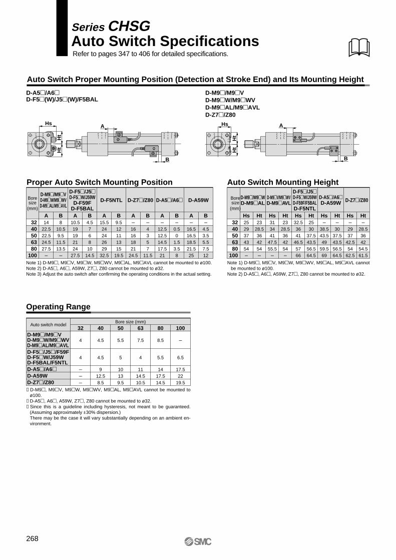
Auto Switch Proper Mounting Position (Detection at Stroke End) and Its Mounting Height
Operating Range
Ht
Ht
Hs
B
A
D-A5�/A6�D-F5�(W)/J5�(W)/F5BAL
Ht
Ht
Hs
B
A
Proper Auto Switch Mounting Position
Boresize
(mm)
3240506380
100
Auto Switch Mounting Height
A14
22.522.524.527.5
–
B8
10.59.511.513.5
–
A10.519192124
27.5
B4.576810
14.5
A15.524242629
32.5
B9.512111315
19.5
A–16161821
24.5
B–4357
11.5
A–
12.512.514.517.521
B–
0.50
1.53.58
A–
16.516.518.521.525
B–
4.53.55.57.512
Note 1) D-M9�, M9�V, M9�W, M9�WV, M9�AL, M9�AVL cannot be mounted to ø100.
Note 2) D-A5�, A6�, A59W, Z7�, Z80 cannot be mounted to ø32.
Note 1) D-M9�, M9�V, M9�W, M9�WV, M9�AL, M9�AVL cannot be mounted to ø100.Note 2) D-A5�, A6�, A59W, Z7�, Z80 cannot be mounted to ø32.Note 3) Adjust the auto switch after confirming the operating conditions in the actual setting.
∗ D-M9�, M9�V, M9�W, M9�WV, M9�AL, M9�AVL cannot be mounted to ø100.
∗ D-A5�, A6�, A59W, Z7�, Z80 cannot be mounted to ø32.∗ Since this is a guideline including hysteresis, not meant to be guaranteed.
(Assuming approximately ±30% dispersion.)There may be the case it will vary substantially depending on an ambient en-vironment.
Boresize
(mm)
3240506380
100
Hs–
38.543.549
59.569
Ht–30
37.543.556.564.5
Hs32.53641
46.55766
Ht2530
37.543.556.564.5
Hs313441
47.555.5
–
Ht23
28.5364254–
Hs2529374354–
Ht23
28.5364254–
Hs–2937
42.554
62.5
Ht–
28.53642
54.561.5
D-M9�/M9�VD-M9�W/M9�WVD-M9�AL/M9�AVLD-F5�/J5�/F59FD-F5�W/J59WD-F5BAL/F5NTLD-A5�/A6�D-A59WD-Z7�/Z80
40
4.5
4.5
912.58.5
50
5.5
5
10139.5
63
7.5
4
1114.510.5
Bore size (mm)80
8.5
5.5
1417.514.5
100
–
6.5
17.522
19.5
32
4
4
–––
Auto switch model
D-M9�/M9�VD-M9�W/M9�WVD-M9�AL/M9�AVLD-Z7�/Z80
D-A59WD-F5NTLD-M9�/M9�VD-M9�W/M9�WVD-M9�AL/M9�AVL
D-F5�/J5�D-F5�W/J59W
D-F59FD-F5BAL
D-Z7�/Z80 D-A5�/A6�D-F5�/J5�D-F5�W/J59WD-F59F/F5BALD-F5NTL
D-M9�V/M9�WVD-M9�AVL
D-A5�/A6�D-A59W D-Z7�/Z80D-M9�/M9�W
D-M9�AL
268
Auto Switch SpecificationsSeries CHSG
Refer to pages 347 to 406 for detailed specifications.
∗ Solid state auto switches are also available with pre-wired connector. Contact SMC for detailed auto switch specifications. Refer to pages 389 and 390 for details.
Besides the models listed in “How to Order,” the following auto switches are applicable.Refer to pages 347 to 406 for detailed auto switch specifications.
Auto switch type Part no. FeaturesElectrical entryD-M9NV, M9PV, M9BVD-M9NWV, M9PWV, M9BWVD-M9NAVL, M9PAVL, M9BAVLD-F59, F5P, J59D-F59W, F5PW, J59WD-F5BALD-F5NTLD-A53, A56D-A67
—Diagnostic indication (2-color display)Water resistant (2-color display)
—Diagnostic indication (2-color display)Water resistant (2-color display)
With timer—
Without indicator light
Grommet (perpendicular)
Grommet (in-line)
Grommet (in-line)
Solid state
Reed
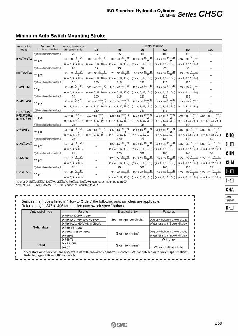
Minimum Auto Switch Mounting Stroke
Auto switchmodel
Auto switchmounting number
2 (Different surfaces and same surface), 1
"n" pcs.
2 (Different surfaces and same surface), 1
"n" pcs.
2 (Different surfaces and same surface), 1
"n" pcs.
2 (Different surfaces and same surface), 1
"n" pcs.
2 (Different surfaces and same surface), 1
"n" pcs.
2 (Different surfaces and same surface), 1
"n" pcs.
2 (Different surfaces and same surface), 1
"n" pcs.
2 (Different surfaces and same surface), 1
"n" pcs.
2 (Different surfaces and same surface), 1
"n" pcs.
20
20
25
25
20
25
25
30
25
Mounting bracket otherthan center trunnion
Center trunnion32 50 63 80 10040
–
–
–
–
–
–
–
–
150
165
145
155
125
(n = 4, 8, 12, 16···)
(n = 4, 8, 12, 16···)
(n = 4, 8, 12, 16···)
(n = 4, 8, 12, 16···)
(n = 4, 8, 12, 16···)
(n = 4, 8, 12, 16···)
(n = 4, 8, 12, 16···)
(n = 4, 8, 12, 16···)
(n = 4, 8, 12, 16···)
(n = 4, 8, 12, 16···)
(n = 4, 8, 12, 16···)
(n = 4, 8, 12, 16···)
(n = 4, 8, 12, 16···)
(n = 4, 8, 12, 16···)
(n – 4)2
(n = 4, 8, 12, 16···)
(n = 4, 8, 12, 16···)
(n = 4, 8, 12, 16···)
(n = 4, 8, 12, 16···)
(n = 4, 8, 12, 16···)
(n = 4, 8, 12, 16···)
(n = 4, 8, 12, 16···)
(n = 4, 8, 12, 16···)
(n = 4, 8, 12, 16···)
(n – 4)2
(n = 4, 8, 12, 16···)
(n = 4, 8, 12, 16···)
(n = 4, 8, 12, 16···)
(n = 4, 8, 12, 16···)
(n = 4, 8, 12, 16···)
(n = 4, 8, 12, 16···)
(n = 4, 8, 12, 16···)
(n = 4, 8, 12, 16···)
(n = 4, 8, 12, 16···)
(n – 4)2
(n = 4, 8, 12, 16···)
(n = 4, 8, 12, 16···)
(n = 4, 8, 12, 16···)
(n = 4, 8, 12, 16···)
(n = 4, 8, 12, 16···)
(n = 4, 8, 12, 16···)
(n = 4, 8, 12, 16···)
(n = 4, 8, 12, 16···)
(n = 4, 8, 12, 16···)
(n – 4)2
(n = 4, 8, 12, 16···)
(n = 4, 8, 12, 16···)
(n = 4, 8, 12, 16···)
(n = 4, 8, 12, 16···)
(n = 4, 8, 12, 16···)
(n = 4, 8, 12, 16···)
(n – 4)2
(n = 2, 4, 6, 8···)
(n = 2, 4, 6, 8···)
(n = 2, 4, 6, 8···)
(n = 2, 4, 6, 8···)
(n = 2, 4, 6, 8···)
(n = 2, 4, 6, 8···)
(n = 2, 4, 6, 8···)
(n = 2, 4, 6, 8···)
(n = 2, 4, 6, 8···)
(n – 2)2
(n – 4)2
(n – 4)2
(n – 4)2
(n – 4)2
(n – 4)2
(n – 2)2
(n – 4)2
(n – 4)2
(n – 4)2
(n – 4)2
(n – 4)2
(n – 2)2
(n – 4)2
(n – 4)2
(n – 4)2
(n – 4)2
(n – 4)2
(n – 4)2
(n – 2)2
(n – 4)2
(n – 4)2
(n – 4)2
(n – 4)2
(n – 4)2
(n – 4)2
(n – 4)2
(n – 2)2
(n – 4)2
(n – 4)2
(n – 4)2
(n – 4)2
(n – 4)2
(n – 2)2
(n – 4)2
(n – 4)2
(n – 4)2
(n – 4)2
(n – 4)2
(n – 2)2
150 + 55
165 + 55
145 + 55
155 + 55
125 + 55 (n – 4)2
(n – 4)2
(n – 4)2
(n – 4)2
(n – 4)2
(n – 2)2
(n – 4)2
(n – 4)2
(n – 4)2
(n – 4)2
(n – 2)2
D-M9�/M9�W
D-M9�V/M9�WV
D-M9�AL
D-M9�AVL
D-F5�/J5�D-F5�W/J59WD-F5BAL/F59F
D-F5NTL
D-A5�/A6�
D-A59W
D-Z7�/Z80
Note 1) D-M9�, M9�V, M9�W, M9�WV, M9�AL, M9�AVL cannot be mounted to ø100.Note 2) D-A5�, A6�, A59W, Z7�, Z80 cannot be mounted to ø32.
115
95
135
135
140
155
135
145
115
105
85
125
125
135
150
130
135
105
100
80
120
120
130
145
120
130
100
95
75
115
115
125
140
120
125
95
115 + 40
95 + 30
135 + 40
135 + 30
140 + 55
155 + 55
135 + 55
145 + 55
115 + 40
85
65
100
100
110
125
–
–
–
–
–
–
105 + 40
85 + 30
125 + 40
125 + 30
135 + 55
150 + 55
130 + 55
135 + 55
105 + 40
100 + 40
80 + 30
120 + 40
120 + 30
130 + 55
145 + 55
120 + 55
130 + 55
100 + 40
95 + 40
75 + 30
115 + 40
115 + 30
125 + 55
140 + 55
120 + 55
125 + 55
95 + 40
85 + 40
65 + 30
100 + 40
100 + 30
110 + 55
125 + 55
20 + 40
20 + 30
25 + 40
25 + 30
20 + 55
25 + 55
25 + 55
30 + 55
25 + 40
Series CHSGISO Standard Hydraulic Cylinder16 MPa
269
CHQ
CHK�
CHN
CHM
CHS�
CH2�
CHA
D-�
RelatedEquipment
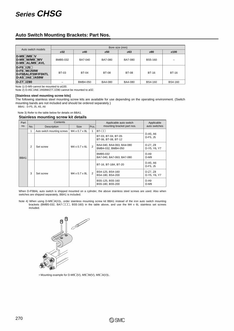
Auto Switch Mounting Brackets: Part Nos.
[Stainless steel mounting screw kits]The following stainless steel mounting screw kits are available for use depending on the operating environment. (Switch mounting bands are not included and should be ordered separately.)
BBA1 : D-F5, J5, A5, A6
Note 3) Refer to the table below for details on BBA1.
Auto switch modelsBore size (mm)
D-M9�/M9�VD-M9�W/M9�WVD-M9�AL/M9�AVLD-F5�/J5�D-F5�W/J59WD-F5BAL/F59F/F5NTLD-A5�/A6�/A59WD-Z7�/Z80
ø32
BMB5-032
BT-03
–
ø40
BA7-040
BT-04
BMB4-050
ø50
BA7-080
BT-08
BA4-080
ø63
BA7-080
BT-08
BA4-080
ø80 ø100
BS5-160
BT-16
BS4-160
–
BT-16
BS4-160
Note 1) D-M9 cannot be mounted to ø100.Note 2) D-A5�/A6�/A59W/Z7�/Z80 cannot be mounted to ø32.
When D-F5BAL auto switch is shipped mounted on a cylinder, the above stainless steel screws are used. Also when switches are shipped separately, BBA1 is included.
Note 4) When using D-M9�A(V)L, order stainless mounting screw kit BBA1 instead of the iron auto switch mounting brackets (BMB5-032, BA7-���, BS5-160) in the table above, and use the M4 x 6L stainless set screws included.
• Mounting example for D-M9�(V), M9�W(V), M9�A(V)L.
BBA1
M4 x 0.7 x 8L
M4 x 0.7 x 6L
M4 x 0.7 x 8L
No.
11
2
3
2
2
BT-��
BT-03, BT-04, BT-05BT-06, BT-08, BT-12
BT-16, BT-18A, BT-20
BA4-040, BA4-063, BA4-080BMB4-032, BMB4-050
BS4-125, BS4-160BS4-180, BS4-200
BS5-125, BS5-160BS5-180, BS5-200
BMB5-032BA7-040, BA7-063, BA7-080
D-A5, A6D-F5, J5
D-A9D-M9
D-Z7, Z8D-Y5, Y6, Y7
D-A5, A6D-F5, J5
D-A9D-M9
D-Z7, Z8D-Y5, Y6, Y7
Stainless mounting screw kit detailsPartno.
Contents
Description
Auto switch mounting screws
Set screw
Set screw
Size Pcs.Applicable auto switch
mounting bracket part nos.Applicable
auto switches
Series CHSG
270

How to Mount and Move the Auto Switch
Put the auto switch on the surface of the cylinder tube.
Cylinder tube
Tie-rod
Watchmaker’s (precision) screwdriver
Auto switchmounting bracket
Hexagon socket head set screwM4
Auto switch
Auto switchmounting screwM2.5 x 0.45 x 4 l
r
e
w
q
1. Fix it to the detecting position with a set screw by installing an auto switch mounting bracket in cylinder tie-rod and letting the bottom surface of an auto switch mounting bracket contact the cylinder tube firmly.
2. Fix it to the detecting position with a hexagon socket head set screw (M4).
(Use a hexagon wrench.)3. Fit an auto switch into the auto switch mounting groove to set it
roughly to the mounting position for an auto switch.4. After confirming the detecting position, tighten up the mounting
screw (M2.5) attached to an auto switch, and secure the auto switch.
5. When changing the detecting position, carry out in the state of 3.
Note 1) To protect auto switches, ensure that main body of an auto switch should be embedded into auto switch mounting groove with a depth of 15 mm or more.
Note 2) Set the tightening torque of a hexagon socket head set screw (M4) to be 1 to 1.2 N·m.
Note 3) When tightening an auto switch mounting screw (M2.5), use a watchmaker’s screwdriver with a grip diameter of 5 to 6 mm.Also, set the tightening torque to be 0.05 to 0.15 N·m. As a guide, turn 90° from the position where it comes to feel tight.
<Applicable auto switch>Solid state ······ D-M9N(V), D-M9P(V), D-M9B(V)
D-M9NW(V), D-M9PW(V), D-M9BW(V)D-M9NA(V), D-M9PA(V), D-M9BA(V)
<Applicable auto switch>Reed ······ D-Z73, D-Z76, D-Z80
1. Fix it to the detecting position with a hexagon socket head set screw (M4) by installing an auto switch mounting bracket in cylinder tie-rod and letting the bottom surface of an auto switch mounting bracket contact the cylinder tube firmly. (Use a hexagon wrench)
2. Fit an auto switch into the auto switch mounting groove to set it roughly to the auto switch mounting position for an auto switch.
3. After confirming the detecting position, tighten up the mounting screw (M2.5) attached to an auto switch, and secure the switch.
4. When changing the detecting position, carry out in the state of 2.
Note 1) To protect auto switches, ensure that main body of an auto switch should be embedded into auto switch mounting groove with a depth of 15 mm or more.
Note 2) Set the tightening torque of a hexagon socket head set screw (M4) to be 1 to 1.2 N·m.
Note 3) When tightening an auto switch mounting screw (M2.5), use a watchmaker’s screwdriver with a grip diameter of 5 to 6 mm.Also, set the tightening torque to be 0.05 to 0.15 N·m. As a guide, turn 90° from the position where it comes to feel tight.
Hexagon socket head set screw (M4)
Auto switch mounting bracket
Auto switch
Watchmaker’s (precision) screwdriver
Auto switchmounting screw (M2.5)
271
Series CHSGISO Standard Hydraulic Cylinder16 MPa
CHQ
CHK�
CHN
CHM
CHS�
CH2�
CHA
D-�
RelatedEquipment
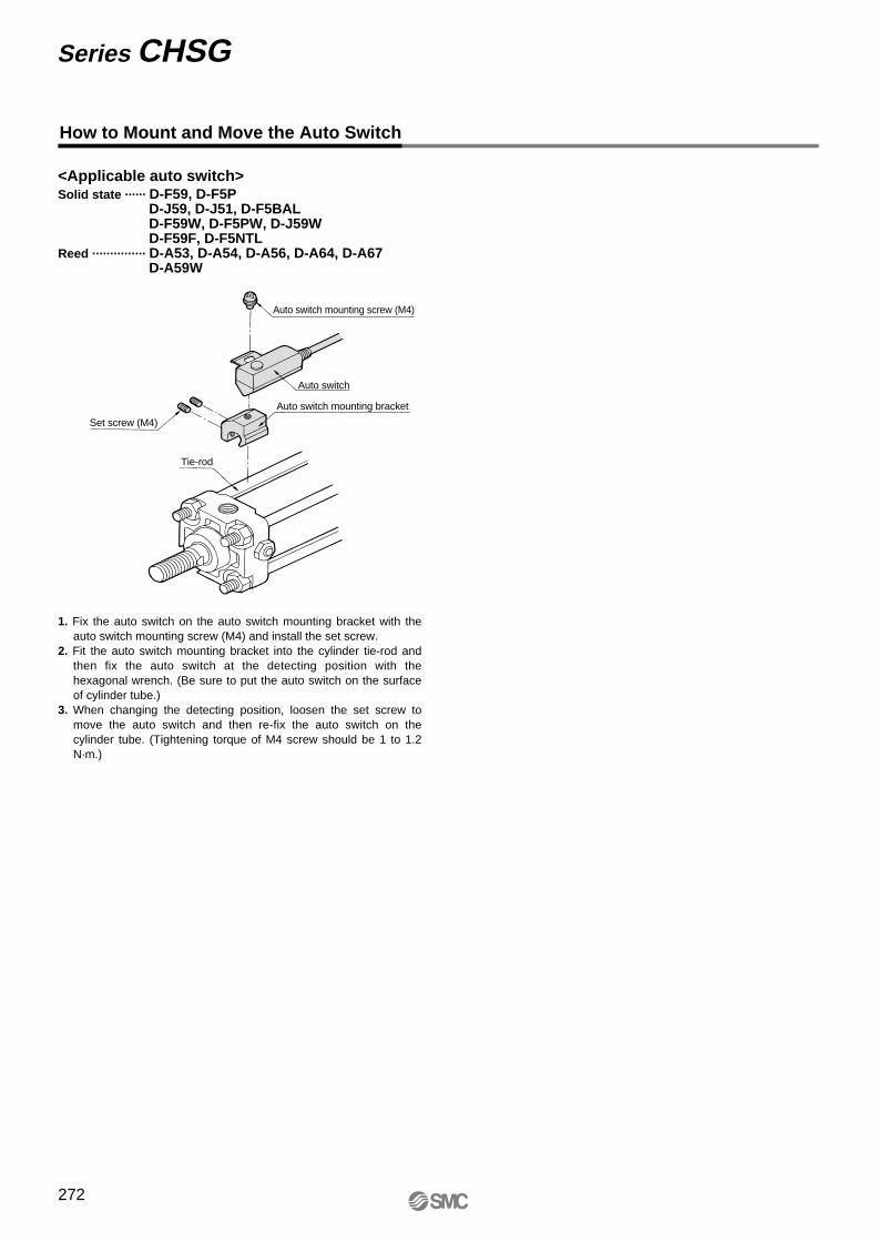
How to Mount and Move the Auto Switch
1. Fix the auto switch on the auto switch mounting bracket with the auto switch mounting screw (M4) and install the set screw.
2. Fit the auto switch mounting bracket into the cylinder tie-rod and then fix the auto switch at the detecting position with the hexagonal wrench. (Be sure to put the auto switch on the surface of cylinder tube.)
3. When changing the detecting position, loosen the set screw to move the auto switch and then re-fix the auto switch on the cylinder tube. (Tightening torque of M4 screw should be 1 to 1.2 N·m.)
<Applicable auto switch>Solid state ······ D-F59, D-F5P
D-J59, D-J51, D-F5BALD-F59W, D-F5PW, D-J59WD-F59F, D-F5NTL
Reed ··············· D-A53, D-A54, D-A56, D-A64, D-A67D-A59W
Auto switch mounting screw (M4)
Auto switch
Auto switch mounting bracket
Set screw (M4)
Tie-rod
Series CHSG
272