iso/iec jtc1/sg29/wg1 n1017 - the coverpagesxml.coverpages.org/dig2000-wg1n1017.pdftel: +1 716 726...
TRANSCRIPT

ISO/IEC JTC1/SG29/WG1 N1017October 30, 1998
Title DIG2000 file format proposal
Source Digital Imaging GroupJ. Scott Houchin, Chair, DIG2000 Working Group901 Elmgrove Road, Rochester, NY 14653–5555Tel: +1 716 726 7984; Fax: +1 716 726 7295; E-mail: [email protected]
The contents of this document represents a consensus of opinion from the following DIG member companies: Agfa, Canon, Corbis, Eastman Kodak, Fuji, Hewlett-Packard, Intel, Interactive Pictures, Iterated Systems, Konica, Live Picture, and TrueSpectra.
Project JPEG 2000
Status Proposal
Requested action Recipients of this document are invited to review this proposal and submit any comments to the DIG2000 Working Group Chair. Recipients of this document are also invited to submit, with their comments, notification of any relevant patent rights of which they are aware and to provide supporting documentation. The DIG2000 Working Group intents to meet in January 1999 to resolve all com-ments with the existing proposal.
Distribution JPEG 2000 Community
ContactISO/IEC JTC 1/SC 29/WG 1 Convener—Dr. Daniel LeeHewlett–Packard Company, 11000 Wolfe Road, MS42U0, Cupertino, CA 95014, USATel: +1 408 447 4160, Fax: +1 408 447 2842, E-mail: [email protected]
ISO/IEC JTC1/SC29/WG1(ITU–T SG8)
Coding of Still Pictures
JBIGJoint Bi-level Image
Experts Group
JPEGJoint Photographic
Experts Group


Contents
Chapter 1 Introducing DIG2000 1
1.1 The goals of the DIG2000 file format 1
1.1.1 DIG2000 vision 1
1.1.2 DIG2000 features 21.1.2.1 Efficient access to the JPEG 2000 bitstream 21.1.2.2 Unambiguous specification of color 21.1.2.3 Flexible metadata architecture 2
1.1.3 DIG2000 reference implementation 3
1.2 About the Digital Imaging Group 3
1.3 About this document 4
1.3.1 Document sections 4
1.3.2 Typographical conventions 4
1.4 Path forward 5
Chapter 2 Coordinate systems 7
2.1 Resolution independent coordinates 7
2.2 Resolution dependent coordinates 8
2.3 Translating coordinates between resolutions 9
2.3.1 Guaranteeing alignment between resolutions 9
2.3.2 Resolution sizes 10
Chapter 3 Binary container 11
ISO/IEC JTC1/SG29/WG1 N1017 iii

3.1 Required functionality of the binary container 11
3.1.1 Efficient random access 11
3.1.2 Size extensibility 11
3.1.3 Streamability 12
3.2 Structured storage 12
3.2.1 Structured storage as a virtual file system 12
3.2.2 Class ID’s 13
3.3 File identification 14
3.3.1 DIG2000 class ID 14
3.4 Standard entities in a DIG2000 file 14
Chapter 4 Metadata organization 17
4.1 Requirements for a metadata architecture 17
4.1.1 Extensibility independent of a standardization process 17
4.1.2 Rapid access to a catalog of metadata 17
4.1.3 Standard metadata block descriptions 18
4.1.4 Image data as metadata 18
4.1.5 Adding and updating metadata 18
4.2 Standard representations of data types in CDATA attributes 18
4.3 Metadata Root structure specification 19
4.4 Metadata Root element descriptions 20
4.4.1 DIG2000ImgSpec 20
4.4.2 ImgSize 20
4.4.3 DefaultDisplaySize 20
4.4.4 InputColor 21
4.4.5 ChannelList 21
4.4.6 Channel 22
4.4.7 DIG2000MetadataSpec 22
4.5 The Image Stream metadata block 24
4.6 Defining new metadata blocks 25
4.7 Example Metadata Root 25
iv October 30, 1998

DIG2000 file format proposal
Chapter 5 Standard metadata fields 29
5.1 Digital Image Source block 30
5.1.1 Metadata block structure values 30
5.1.2 Document type definition 30
5.1.3 Element definitions 345.1.3.1 DigitalImageSource 345.1.3.2 CameraCapture 355.1.3.3 CameraInformation 355.1.3.4 DigitalCaptureDeviceCharacterization 355.1.3.5 SpatialFrequencyResponse 365.1.3.6 SFRRow 365.1.3.7 CFAPattern 365.1.3.8 CFARow 365.1.3.9 Red, Green, Blue, Cyan, Magenta, Yellow, White 375.1.3.10 OECF 375.1.3.11 OECFRow 375.1.3.12 CameraCaptureSettings 375.1.3.13 SpecialEffects 405.1.3.14 SpEfUnidentified, SpEfNone, SpEfColored, SpEfDiffusion,
SpEfMultiImage, SpEfPolarizing, SpEfSplitField and SpEfStar 405.1.3.15 Notes 415.1.3.16 CapturedItem 415.1.3.17 OriginalScene 415.1.3.18 ReflectionPrint 415.1.3.19 PrintedItem 415.1.3.20 Film 415.1.3.21 ComputerGenerated 425.1.3.22 OtherItem 425.1.3.23 ScannerCapture 425.1.3.24 ScannerInformation 42
5.1.4 Examples 435.1.4.1 A simple DigitalImageSource 435.1.4.2 A complex DigitalImageSource 44
5.2 Intellectual Property block 45
5.2.1 Metadata block structure values 45
5.2.2 Document type definition 45
5.2.3 Element definitions 465.2.3.1 IntellectualProperty element 465.2.3.2 Copyright 465.2.3.3 Pricing 465.2.3.4 Notes 46
5.2.4 Example 46
5.2.5 Intellectual property issues 47
ISO/IEC JTC1/SG29/WG1 N1017 v

5.3 Content Description block 48
5.3.1 Metadata block structure values 48
5.3.2 Document type definition 48
5.3.3 Element definitions 485.3.3.1 ContentDescription 485.3.3.2 RollCaption 495.3.3.3 Caption 495.3.3.4 People 495.3.3.5 Places 495.3.3.6 Things 495.3.3.7 Events 495.3.3.8 Notes 49
5.3.4 Example 50
5.4 GPS Information block 50
5.4.1 Metadata block structure values 50
5.4.2 Document type definition 50
5.4.3 Element descriptions 515.4.3.1 GPSInformation 51
5.4.4 Example 53
Chapter 6 Color representation 55
6.1 Introduction 55
6.2 sRGB 56
6.2.1 Introduction 56
6.2.2 Reference conditions 566.2.2.1 Reference display conditions 566.2.2.2 Reference viewing conditions 576.2.2.3 Reference observer conditions 57
6.2.3 Encoding characteristics 576.2.3.1 Introduction 576.2.3.2 Transformation from RGB values to 1931 CIE xyz values 586.2.3.3 Transformation from 1931 CIE xyz values to RGB values 58
6.3 International Color Consortium (ICC) profiles 59
6.3.1 Intended audience of the ICC profile specification 60
6.3.2 ICC device profiles 60
6.3.3 ICC profile structure 60
6.3.4 Embedded ICC profiles 61
6.4 Color representation specification 61
vi October 30, 1998

DIG2000 file format proposal
Appendices
Appendix A Structured Storage 65
A.1 Compound file binary format 65
A.1.1 Overview 65
A.1.2 Sector types 66A.1.2.1 Header 66A.1.2.2 Fat sectors 67A.1.2.3 MiniFat sectors 68A.1.2.4 DIF sectors 69A.1.2.5 Directory sectors 69
A.1.2.5.1 Root Directory Entry 71A.1.2.5.2 Other Directory Entries 72
A.1.2.6 Storage sectors 72
A.1.3 Examples 72A.1.3.1 Sector 0: Header 72A.1.3.2 SECT 0: First (only) FAT sector 73A.1.3.3 SECT 1: First (only) Directory sector 73
A.1.3.3.1 SID 0: Root Directory Entry 73A.1.3.3.2 SID 1: “Storage 1” 74A.1.3.3.3 SID 2: “Stream 1” 74A.1.3.3.4 SID 3: Unused 75
A.1.3.4 SECT 3: MiniFat sector 75A.1.3.5 SECT 4: MiniStream (data of “Stream 1”) 75
A.2 OLE Property Set binary format 76
A.2.1 Document properties in storage 76
A.2.2 Format of the primary property set stream 77A.2.2.1 Property Set header 78A.2.2.2 Format ID/Offset pairs 78A.2.2.3 Sections 79
A.2.3 Special property ids 79A.2.3.1 Property ID zero: Dictionary of property names 79A.2.3.2 Property ID one: Code Page Indicator 80A.2.3.3 Property ID 0x80000000: Locale Indicator 81A.2.3.4 Reserved property ID’s 82
A.2.4 Property type representations 82
ISO/IEC JTC1/SG29/WG1 N1017 vii

A.3 CompObj stream binary format 85
A.3.1 Overview 85
A.3.2 Format 86A.3.2.1 Mandatory part 86
A.3.2.1.1 Stream name 86A.3.2.1.2 Header 86A.3.2.1.3 User Type 86A.3.2.1.4 Clipboard Format (ANSI) 87
A.3.2.2 Optional: ProgID (ANSI) 87A.3.2.3 Optional: Unicode versions 87
A.3.2.3.1 Magic Number 87A.3.2.3.2 User Type (Unicode) 87A.3.2.3.3 Clipboard Format (Unicode) 88A.3.2.3.4 ProgID (Unicode) 88
Appendix B Example API 89
B.1 Using the ImageSource interface 89
B.1.1 Introduction 89
B.1.2 Image representation 90B.1.2.1 Multiple resolutions 90B.1.2.2 Tiles 90B.1.2.3 Example 90
B.1.3 Loading an image 90
B.1.4 Getting tiles 91
B.2 C++ documentation 92
B.2.1 .fpx-format related interfaces 92B.2.1.1 Interfaces 926.4.0.1 See Also 93
B.2.2 ImageSource related Interfaces 93B.2.2.1 Interfaces 93B.2.2.2 See Also 94
B.2.3 Property Set related Interfaces 94B.2.3.1 Interfaces 94
B.2.4 Render2D Base Types 94
B.2.5 Hierarchy of C++ Classes 95
Appendix C Enhancements for Windows 97
C.1 Property sets 97
viii October 30, 1998

DIG2000 file format proposal
C.2 Summary Information property set 98
C.3 CompObj stream 100
Appendix D References 103
ISO/IEC JTC1/SG29/WG1 N1017 ix


1: Introducing DIG2000
The JPEG 2000 compression standard is shaping up to be a great way to compress raw image data. It is expected to contain features that will enable applications to access and decompress the image data in many different forms and scenarios. This will enable many new digital imaging applications and help to make digital images as ubiquitous as scalable fonts.
However, a compression standard solves only part of the problem. For an applica-tion to be able to use a digital image effectively, the compressed image data must be wrapped in a complete file format that tells the application about the raw image data. This information can range from unambiguously specifying the color-space of the image data, to specifying the names of the people, places and things that are pictured in the image.
This document proposes a file format that meets the needs of present and future imaging applications to fully describe digital images. This file format is affection-ately known as the DIG2000 file format.
1.1 The goals of the DIG2000 file format
1.1.1 DIG2000 visionThe DIG2000 file format was designed as a way to completely specify a digital image while still allowing effective access to both the digital image data and the meta-data. The vision of the DIG2000 working group is as follows:
To create a digital image file format that embodies a tightly-integrated set of essen-tial features for specifying digital images and provides the needed mechanisms for images to be used effectively.
There are several important aspects to the vision. First and most importantly, the DIG2000 format should be a format for storing digital images. Although many other formats provide additional functionality, there is often a price to be paid, and there is often a better way to achieve the same result by concatenating the digital image file format standard with other standards as opposed to trying to convolve multi-ple standards. This means that as the DIG2000 working group evaluated features to add to the standard, they were measured as to how essential they were to the spec-ification of digital images.
Secondly, it was important to develop features in such a way as to maximize the performance of imaging applications that use these image files. An application
ISO/IEC JTC1/SG29/WG1 N1017 1

The goals of the DIG2000 file format
must be able to create an image file that effectively answers the needs set forth by that application’s scenarios.
For example, if an image file is being used as part of a page layout being designed in DTP software, it may be very important for that application to write the file in such a way as to maximize performance in a progressive-by-resolution mode. In other applications, it may be very important that the application can add addi-tional metadata to the file without requiring that the entire file be rewritten.
1.1.2 DIG2000 featuresThe DIG2000 format embodies the following features, each of which is considered essential to the specification of a digital image and essential for the image file to be used effectively.
1.1.2.1 Efficient access to the JPEG 2000 bitstreamThe JPEG 2000 bitstream is stored in a DIG2000 file as an independent and unadulter-ated object. It must be possible for an application to quickly gain access to the bitstream, to either load the bitstream in a random fashion or to stream it to a client.
1.1.2.2 Unambiguous specification of colorThe file format must be able to unambiguously specify the colorspace of the raw image data stored in the JPEG 2000 bitstream. This can be accomplished by using the default assumption of the standard sRGB colorspace, or by storing an ICC input pro-file in the file.
1.1.2.3 Flexible metadata architectureThe ability to store metadata in the file is very important. However, it is not possi-ble to determine today all of the types of metadata that applications will deem as essential in the future. Thus it is important that the file format contain a mecha-nism to add new types of metadata to the file without going through a standardization or tag registration process.
Also, as images files are used, existing metadata fields will continually be updated and new metadata fields will be added to the file. For example, when the scene is digitized, an image file is created that contains information about the digitization environment. In many professional workflows, the image file will be loaded into an application and the digitized scene will be examined. The image file will then be updated with new information about the scene, such as the names of the people in the scene, where the scene was captured, and when it was captured. As copy-rights are often very fluid and change over time, the copyright and intellectual property information in the file may change several times over the life of the digi-tal image file. At a later point, the image file may again be updated with new metadata. For metadata to be efficiently added to the image file, it must be possi-ble to add additional blocks of data to the file without rewriting a large portion of the file. If an image file contains 20MB of compressed image data, rewriting the image file becomes a costly step in many workflows.
2 October 30, 1998

DIG2000 file format proposal
It is also important to provide a means to dynamically update the metadata in the file. For example, in today’s systems, it is impossible to update the metadata in a file on a user’s system from a server without downloading a new copy of the file. A dynamic updating mechanism would allow an application to check a server for just the updated portions of an image file and download those that have changed since the user’s copy of the file was last written.
1.1.3 DIG2000 reference implementationThe Digital Imaging Group intents to begin work on a reference implementation of the DIG2000 proposal for the JPEG 2000 effort. As part of this effort, TrueSpectra intends to release the source code for their Flashpix™ file format and Internet Imaging Protocol (IIP) client software license and royalty free. This software includes a custom implementation of the Microsoft Structured Storage container document format. This software will be released upon resolution of the intellectual property issues with Microsoft around the Structured Storage format, and provided that the technology is positively received by the JPEG 2000 committee.
1.2 About the Digital Imaging Group
The Digital Imaging Group (DIG) is an imaging industry consortium that was founded in 1997 by Adobe, Canon, Eastman Kodak, Fuji, Hewlett-Packard, IBM, Intel, Live Picture and Microsoft. Since that time, the organization has grown to over 50 members at three different levels of membership.
The organization was formed to provide the industry a forum for the exploration, implementation, and stewardship of technologies and methods for expanding the digital imaging market. The DIG has been very active in the area of resolution-inde-pendent image access and transmission with its first two digital imaging solutions, Flashpix and the Internet Imaging Protocol (IIP). The organization’s success can be measured by the fact that over the past 18 months, DIG member companies have released over 100 products supporting its initiatives.
The attractive capabilities of the JPEG 2000 bitstream were recognized by DIG mem-ber companies. To respond to the need for a standard file format to wrap JPEG 2000 compressed image data, the DIG formed a working group (the DIG2000 working group) in late summer 1998 to address the issue. The members of this working group are Agfa, Canon, Corbis, Eastman Kodak, Fuji, Hewlett-Packard, Intel, Interac-tive Pictures, Iterated Systems, Konica, Live Picture, Microsoft, and TrueSpectra.
Specifications and proposals are approved within the DIG2000 working group using methods similar to those used in ISO. All proposals are voted on by all voting eligi-ble members of the group, which is determined by the level at which each company has joined the DIG. In the DIG2000 working group, all members are eligible to vote with the exception of Microsoft.
The proposal contained within this document represents the opinion of the work-ing group, and thus the DIG as a whole. Each aspect of this proposal has been approved by a majority of members of the working group, and the proposal as a whole has been approved by the DIG management committee.
ISO/IEC JTC1/SG29/WG1 N1017 3

About this document
1.3 About this document
1.3.1 Document sectionsThis document is organized into the following sections:
Chapter 1: Introducing DIG2000. This chapter introduces the Digital Imaging Group, the DIG2000 working group, and the goals of this proposal.
Chapter 2: Coordinate systems. This chapter describes the standard coordi-nate system for both resolution dependent and resolution independent measurement of the image.
Chapter 3: Binary container. This chapter describes the binary container for-mat for the DIG2000 file format.
Chapter 4: Metadata organization. This chapter describes the metadata architecture of the DIG2000 file format.
Chapter 5: Standard metadata fields. This chapter describes the standard metadata fields in a DIG2000 file.
Chapter 6: Color representation. This chapter describes how the colorspace of decompressed data is specified and how that color information should be inter-preted when loading and processing the image.
Appendix A: Structured Storage. This appendix defines the binary format for the Microsoft Structured Storage container document format.
Appendix B: Example API. This appendix shows an example API for using DIG2000 files.
Appendix C: Enhancements for Windows. This appendix defines specific enhancements that can be made to a DIG2000 file for use in Windows platforms.
Appendix D: References. This appendix lists all documents referenced by this proposal, as well as other documents that the reader of this proposal may find interesting or helpful.
1.3.2 Typographical conventionsThe following typographical conventions are used throughout this document:
◆ Syntax, and code examples are shown in fixed width font.
◆ Octal encoding of characters within this text will be shown in bold , with the octal value preceded by a \ (i.e. \040 is the space character). For example, the text Metadata \040 Root refers to the literal string “Metadata Root” where the blank refers to exactly one space character.
4 October 30, 1998
DIG2000 file format proposal
◆ Italic strings are used for emphasis and to identify words representing variable entities in the text.
◆ Bold strings are used to identify the first instance of a word requiring definition.
1.4 Path forward
This document represents a consensus opinion of the DIG. It integrates those tech-nologies that the DIG believes are most essential for a successful digital image format.
However, due to time constraints, the DIG was not able to fully investigate all tech-nologies that could augment the DIG2000 format. As part of the effort to resolve comments received on this version of the proposal, the DIG will continue to investi-gate other technologies, including:
◆ Specifying hot-spots in the image◆ Universal Transverse Mercator (UTM) coordinates for GPS data◆ The use of XML-data, RDF and WIDL for the storage of metadata◆ Bézier clipping paths◆ A standard naming scheme for metadata blocks to minimize conflicts
The DIG2000 working group plans on meeting in January 1999 to resolve all com-ments received and to integrate other investigated technologies. All comments on this proposal should be sent to J. Scott Houchin at [email protected].
ISO/IEC JTC1/SG29/WG1 N1017 5


2: Coordinate systems
DIG2000 files allow the image data to be accessed at several different resolutions. To effectively use the image, it is very important to be able to specify the location of features in the image both independently of any particular resolution, and on a pixel neighborhood basis within a particular resolution.
The DIG2000 format defines two different, yet related coordinate systems: a resolu-tion independent system and a resolution dependent system.
2.1 Resolution independent coordinates
In many situations, the scene must be described by a coordinate system indepen-dent of the pixel. For example, in a graphic illustration application, an artist may have specified that a piece of vector based art be aligned with a particular feature in a raster based object. Over its life, the illustration may be rendered at many dif-ferent resolutions: it may be drawn to the computer screen at 72 DPI, rendered for a laser proof at 300 DPI, and rendered for final printing plates at 2400 DPI, for example. It is very important that the application be able to easily and consistently specify the location of features in the image.
Figure 2.1 shows a resolution independent coordinate system. The image is described in a Cartesian system, with the x-axis horizontal and pointing to the right, the y-axis vertical and pointing downward, and the origin at the upper left corner. The scale is such that the height of the image is normalized to 1.0. To keep the scale of the x-axis and the y-axis the same, the image width is its aspect ratio (width/height). Thus, a square portion of any image has equal width and height in this coordinate system.
ISO/IEC JTC1/SG29/WG1 N1017 7

Resolution dependent coordinates
FIGURE 2.1 Resolution independent coordinates
2.2 Resolution dependent coordinates
At a given resolution, the normalized coordinate system described above must be converted to a set of discrete pixels neighborhoods. To do this, the continuous reso-lution dependent coordinate system in Figure 2.2 is used. This is simply a scaled version of the resolution independent coordinates. Each coordinate value The val-ues (x, y) in this coordinate system are still real (floating point) numbers.
To define the actual pixels of the image, an integer grid is overlaid on the coordi-nate system. The discrete pixel referred to by (i, j), where i and j are integers, is centered at location (i+0.5, j+0.5). The half-unit shift makes the conversion between discrete and continuous descriptions simple. The point (x, y) falls in the unit square labelled ( , ) and containing the pixel at ( +0.5, +0.5). No rounding is required.
X
Y
(0,0)
(R, 1)
(R, 0)
(0,1)
RWH----=
x y x y
8 October 30, 1998

DIG2000 file format proposal
FIGURE 2.2 Resolution-dependent coordinates
2.3 Translating coordinates between resolutions
In a DIG2000 file, each resolution in the full hierarchy is separated from the next higher resolution by a spatial factor of 2× in both the x and y directions.
In Figure 2.3, the full resolution image is W rows × H columns. The actual spatial resolution (in pixels per inch, for example) is irrelevant, since neither the desired output size nor the output resolution is known. Each successively smaller resolu-tion has half the number of rows and columns as the previous resolution. In this example, the second resolution is rows × columns (the quotient must be rounded up because the image cannot have fractional pixels).
FIGURE 2.3 Sample resolution hierarchy
2.3.1 Guaranteeing alignment between resolutionsIn a DIG2000 file, it is required that the decomposition process use centered align-ment when subsampling the image to create lower resolution levels, as shown in
X
Y
(0,0) (W,0)
(W,H)(H,0)
1 2
12
…
…
W 2⁄ H 2⁄
W2---- H
2---×
W H×
…W
2n 1–------------ H
2n 1–------------×
ISO/IEC JTC1/SG29/WG1 N1017 9

Translating coordinates between resolutions
Figure 2.4. A pixel in resolution i+1 is centered on the pixels in resolution i that contributed to the lower resolution pixel.
FIGURE 2.4 Subsampling an image using centered alignment
This significantly simplifies the computations needed to keep track of the location of image features between resolutions; using the coordinate system described in Section 2.1, the resolution independent coordinates of a feature do not change from resolution to resolution. If cosited alignment is used, the location of image features does change from resolution to resolution, and it can be very difficult to explain how they change and to implement a system to maintain alignment of multiple resolutions.
2.3.2 Resolution sizesThe size of a decimated image is determined from Equation 2.1, where (w0,h0) is the width and height of the larger resolution and (w1,h1) are the width and height of the smaller resolution:
(2.1)
Note that this rounding affects the size of the image in resolution independent coordinates. The height of the largest resolution image is defined to be 1.0. Using the rounding method in Equation 2.1, the height of one resolution given the height of the next largest resolution can be determined as follows, where h0 is the height of the larger resolution in resolution independent coordinates, p0 is the height of the larger resolution in pixels, h1 is the height of the next smaller resolution in res-olution independent coordinates, and p1 is the height of the next smaller resolution in pixels, as defined by Equation 2.1:
(2.2)
Failing to make this correction to the height and width of the image (in resolution independent coordinates), as further illustrated in [8], when dealing with resolu-tions other than the largest resolution may cause slight errors in the alignment of the multiple resolutions of the image.
X
Y
Resolution i pixels
Resolution i+1 pixels
w1 h1,( ) w0
2------
h0
2-----,
=
h1
2p1
p0--------- h0×=
10 October 30, 1998

3: Binary container
Although the JPEG 2000 bitstream goes far toward organizing the image data in a file, and has a large effect on the value of the image file, it is up to the binary con-tainer of the image to wrap together the image data with all of the other pieces of information that enhance the value of that image. The DIG2000 file format uses Microsoft Structured Storage as the binary container. The complete Structured Stor-age binary format specification can be found in Appendix A.
3.1 Required functionality of the binary container
When selecting a binary container format for the DIG2000 file format, the following functionalities were deemed as required for the format to be successful in typical DIG applications.
3.1.1 Efficient random accessThe binary container must minimize the sequential processing of the image file required to gain random access to individual objects (including objects within the JPEG 2000 bitstream) in the file.
For example, a marker segment architecture like in baseline JPEG can be problem-atic because an application is required to jump from one marker segment to the next, until the desired segment is found. The reader is also required to read a small amount of data from each segment in order to determine the location of the next segment. If there are a large number of segments, it can become very inefficient for a reader to locate a segment toward the end of the file.
It would be much more efficient for the binary format to provide some form of standard “table of contents” that a reader can use quickly determine the exact loca-tion of individual objects in the file.
For example, an IIP server must be able to efficiently access the file in a mode where particular blocks from the image data will be loaded (independently of other blocks) and sent to the client. The client may then request additional blocks of the image to increase the displayed resolution or quality, which the server must again be able to efficiently access and send to the client.
3.1.2 Size extensibilityThe binary container must provide a means to extend the length of individual objects in the file without requiring large portions of the file to be rewritten.
For example, consider a large standard TIFF image with over 20MB of image data. This file contains a comment tag listing most of the people shown in the image. If a
ISO/IEC JTC1/SG29/WG1 N1017 11

Structured storage
user wishes to add a small amount of additional information to the comment tag, the application must rewrite the entire file (over 20MB of data).
This required functionality could be achieved by defining some form of file alloca-tion table within the file format. This would allow a single independent object to be stored across multiple, non-contiguous sections of the image file, much like how a file on a computer hard disk can be stored over multiple, non-contiguous sectors of the disk.
Note that “optimized” files can be written where all objects are stored in sequen-tial, contiguous blocks. In fact, most files when originally written will be optimized. It is only after files are changed that data begins to be organized in a non-optimal fashion. However, it is quite possible to write an application to optimize the objects within a file (like disk optimization applications).
Which brings up the topic of streamability…
3.1.3 StreamabilityIt must be possible to produce a file that is suitable for streaming from a server to a client. This means that the client begins processing the file upon receipt of the first byte and can make effective use of the file as it arrives. The client should never be required to wait for additional data to arrive before it can process data that has already arrived from the file.
In some ways, the requirement of streamability conflicts with the requirements of random access and size extensibility. It will not be possible to traditionally stream all files from a server to a client. For example, as a file is edited and its organiza-tion becomes non-optimal, an application may be required to optimize the file before it can be streamed.
For other applications, a server could be designed to pull portions of different ele-ments of the DIG200 file and interleave the data elements for streaming as per some other standard; the file data is optimized at a protocol layer above the file access layer. For example, a multimedia streaming server might load pieces of the image data and audio data stored in a DIG2000 file and combine them as per the stream-ing protocol for annotated slideshow playback on the client. Another example might be an IIP server where the server extracts different image resolution from arbitrary locations in the file to facilitate client-side zooming and panning.
3.2 Structured storage
3.2.1 Structured storage as a virtual file systemThe DIG2000 digital image format is based on a compound object storage model called Structured Storage. A file in Structured Storage format contains two types of objects: storages and streams. Storages are analogous to directories in a file sys-tem; streams are analogous to files. A storage may contain both zero or more additional storages and zero or more streams. The streams and storages in a
12 October 30, 1998
DIG2000 file format proposal
DIG2000 file are individually addressable. Figure 3.1 shows the convention used in this document to illustrate storages and streams:
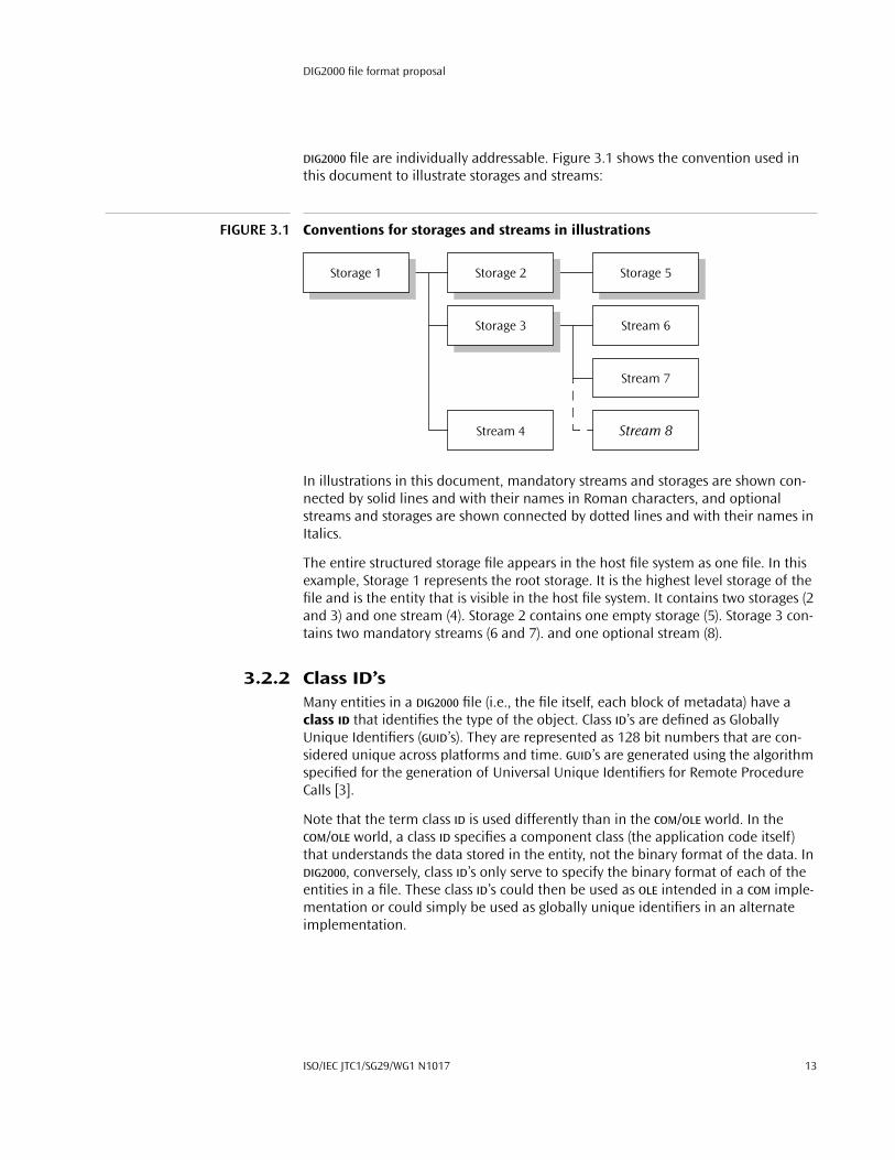
FIGURE 3.1 Conventions for storages and streams in illustrations
In illustrations in this document, mandatory streams and storages are shown con-nected by solid lines and with their names in Roman characters, and optional streams and storages are shown connected by dotted lines and with their names in Italics.
The entire structured storage file appears in the host file system as one file. In this example, Storage 1 represents the root storage. It is the highest level storage of the file and is the entity that is visible in the host file system. It contains two storages (2 and 3) and one stream (4). Storage 2 contains one empty storage (5). Storage 3 con-tains two mandatory streams (6 and 7). and one optional stream (8).
3.2.2 Class ID’sMany entities in a DIG2000 file (i.e., the file itself, each block of metadata) have a class ID that identifies the type of the object. Class ID’s are defined as Globally Unique Identifiers (GUID’s). They are represented as 128 bit numbers that are con-sidered unique across platforms and time. GUID’s are generated using the algorithm specified for the generation of Universal Unique Identifiers for Remote Procedure Calls [3].
Note that the term class ID is used differently than in the COM/OLE world. In the COM/OLE world, a class ID specifies a component class (the application code itself) that understands the data stored in the entity, not the binary format of the data. In DIG2000, conversely, class ID’s only serve to specify the binary format of each of the entities in a file. These class ID’s could then be used as OLE intended in a COM imple-mentation or could simply be used as globally unique identifiers in an alternate implementation.
Storage 1
Stream 6
Storage 5Storage 2
Storage 3
Stream 4
Stream 7
Stream 8
ISO/IEC JTC1/SG29/WG1 N1017 13

File identification
3.3 File identification
3.3.1 DIG2000 class IDDIG2000 files can be identified by the class ID 00000000-5E0C-11D2-9D44-00A0C933BB7F. This class ID must be stored in the header of the root storage of the file (see Appendix A.1.2.1). Many object based systems (e.g. OLE), as well as many Magic Number based systems, will use the class ID found in the header of the root storage as a key for launching an application. In this way an application can be designated to handle all files of this object type by default, regardless of their creator.
On the MacOS, the file type of a DIG2000 file should be set to D2KI 1. On file exten-sion based systems, the file extension should be set to .d2k .
3.4 Standard entities in a DIG2000 file
The following illustration shows the standard entities in a DIG2000 file (Figure 3.2), each of which are stored in a separate stream within the root storage.
FIGURE 3.2 Standard entities in a DIG2000 file
Root storage. This storage represents the DIG2000 file itself. It must have the class ID 00000000-5E0C-11D2-9D44-00A0C933BB7F .
1. It is expected that these values for the MacOS file type and file extension be changed when the final file format name is selected.
Root storage
SummaryInformation
CompObj
MetadataRoot
Image Stream
MetadataBlock 1
MetadataBlock 2
MetadataBlock n–1
Input ColorICC Profile …
14 October 30, 1998
DIG2000 file format proposal
Metadata Root. This stream contains the root structure for all metadata. The structure provides a list of all of the blocks of metadata in the file, as well as directly specifying the values of several required metadata fields (i.e. colorspace, image size). This stream is defined in Section 4.3. The name of this stream must be Metadata \040 Root and it must be located in the root storage of the file. This stream must exist in all valid DIG2000 files.
Image Stream. This stream contains the actual JPEG 2000 encoded bitstream, as defined by other activities in WG1. The name of this stream must be Image \040 Stream and it must be located in the root storage of the file. This stream must exist in all valid DIG2000 files.
Input Color ICC Profile. This stream contains an input color ICC profile, which specifies how colors, as they are actually specified in the decompressed image data, should be converted to the Profile Connection Space (PCS). The name of this stream must be Input \040 Color \040 ICC\040 Profile , and it must be located in the root storage of the file. The data in this stream is in the exact format for input profiles as specified by [2]. A greater discussion of input colorspaces is given in Chapter 6.
Metadata Blocks 1 to n–1. These blocks contain assorted sets of metadata fields. A set of standard blocks are defined in Chapter 5. However, other blocks will be defined by applications independently to the JPEG 2000 standardization process. The names of each of these blocks is defined by the block specification itself.
Summary Information. This stream contains the Summary Information prop-erty set as described in Appendix C.2. This stream is optional, but highly recommended for Windows platforms. However, if this stream exists, the name of this stream must be \005 SummaryInformation and it must be located in the root storage of the file.
CompObj. This stream contains the CompObj information as defined in Appendix C.3. This stream is optional, but highly recommended for Windows plat-forms. However, if this stream exists, the name of this stream must be CompObj and it must be located in the root storage of the file.
ISO/IEC JTC1/SG29/WG1 N1017 15

4: Metadata organization
In some ways, metadata is the most important aspect of a image file format, pri-marily because in many ways, all data in the file, including the image data, is metadata. Thus it is absolutely essential for a digital image file format to have a good architecture for storing, adding and updating metadata.
4.1 Requirements for a metadata architecture
When defining a metadata architecture for the DIG2000 file format, the following functionalities were deemed as required for the format to be successful in typical DIG applications:
4.1.1 Extensibility independent of a standardization processIt must be possible for new metadata properties and groups of properties to be defined and written to files without involving a standardization or registration process.
4.1.2 Rapid access to a catalog of metadataIn many applications, metadata is used in some form of interactive process. Whether that process is controlled by a human user or a computer application, access to metadata is generally requested in a multiple stage process; a list of the types of metadata present is requested first, followed my multiple requests for par-ticular pieces of the data.
For example, an application might first load the catalog of metadata and discover that the image was captured by a digital camera. If the application was interested in the details of the capture (such as the CFA pattern of the camera or the exposure settings), the application would make a second request for that information. How-ever, if the application was not interested in that information, it would not be encumbered by accesses to that data.
As the perceived value of metadata grows, access to metadata will switch from something that is primarily user driven to something that is frequently application driven. It will become essential for an application to be able to quickly load a cata-log or list of the types of metadata stored in the file without requiring that the data itself be loaded or parsed through.
ISO/IEC JTC1/SG29/WG1 N1017 17

Standard representations of data types in CDATA attributes
4.1.3 Standard metadata block descriptionsIn addition to listing each block of metadata in a catalog, it is also important to list attributes of the block of data itself, such as the MIME type of the actual data or the time that data was written to the file.
4.1.4 Image data as metadataA lot of the attributes of a metadata block can be applied to the encoded image data as well. For example, it may be important to reflect the modification date and time of the image data itself independently from the modification date of the file. This functionality would allow an application to judge the validity of particular metadata fields by determining if data on which that field is dependent has changed since the field was written.
4.1.5 Adding and updating metadataIt must be possible to add new metadata to the file or to extend the length of exist-ing metadata blocks without rewriting large portions of the image file. As the value of metadata increases, it will be accessed more and edited and updated more. As this happens, typical image sizes will also be growing. Rewriting nearly an entire large image file when only a few bytes of metadata have changed will cause unac-ceptable performance degradation in many applications.
4.2 Standard representations of data types in CDATA attributes
In the DIG2000 format, all metadata is stored using XML. Unfortunately, there are very few standard data types defined in XML. This section defines several atomic data types as they would be stored in a CDATA attribute in an XML element.
Int. The ASCII string representation of a legal integer i.
PosInt. An Int where i ≥ 0.
CountInt. An Int where i > 0.
Real. The ASCII string representation of a legal real number r.
PosReal. A Real where r ≥ 0.
CountReal. A Real where r > 0.
Timestamp. A string of the form defined by ISO 8601:1998(E) [14].
18 October 30, 1998

DIG2000 file format proposal
4.3 Metadata Root structure specification
The first step in accessing the metadata contained in a DIG2000 file will be loading the Metadata Root stream. This stream provides the application with information about the types and locations of the metadata stored in the file. It also provides information about the image data itself which will be required for acceptable pro-cessing of the image.
The Metadata Root structure is stored as an XML stream. The DTD for the Metadata Root structure is as follows1:
<?xml version="1.0"?><!DOCTYPE DIG2000MetadataRoot [
<!ELEMENT DIG2000MetadataRoot(DIG2000ImgSpec, DIG2000MetadataSpec*)
>
<!ELEMENT DIG2000ImgSpec(ImgSize, DefaultDisplaySize?, InputColor, ColorChannelList)
>
<!ELEMENT ImgSize EMPTY><!ATTLIST ImgWidth
w CDATA #REQUIREDh CDATA #REQUIRED
>
<!ELEMENT DefaultDisplaySize EMPTY><!ATTLIST DefaultDisplaySize
w CDATA #REQUIREDh CDATA #REQUIREDunit (Inches | Meters | Centimeters | Millimeters | Picas |
Points) "Inches">
<!ELEMENT InputColor EMPTY><!ATTLIST InputColor
colorspace (sRGB | Unspecified) #REQUIRED>
<!ELEMENT ChannelList (Channel+)><!ATTLIST ChannelList
n CDATA #REQUIREDpm (True | False) "False"
>
<!ELEMENT Channel EMPTY><!ATTLIST Channel
name CDATA #REQUIREDsize (bit8 | bit16) "bit8"
>
1. The token “DIG2000” is used throughout the XML specifications in this document. However, it is expected that this will be changed to a standard JPEG 2000 name before final specification of the standard.
ISO/IEC JTC1/SG29/WG1 N1017 19

Metadata Root element descriptions
<!ELEMENT DIG2000MetadataSpec ANY><!ATTLIST DIG2000MetadataSpec
name CDATA #REQUIREDmimeType CDATA #REQUIREDspecID CDATA #REQUIREDinstance ID #IMPLIEDeditable (Edit | Locked) "Edit"
downloadPriority (Immediate | Delayed | OnRequest)"OnRequest"
creationDate CDATA #REQUIREDmodificationDate CDATA #REQUIREDstream CDATA #IMPLIEDremote CDATA #IMPLIED
>]>
4.4 Metadata Root element descriptions
The Metadata Root structure (an element of DIG2000MetadataRoot ) contains two types of elements: one DIG2000ImgSpec , followed by zero or more DIG2000MetadataSpec ’s. The file must contain one DIG2000MetadataSpec for every block of metadata in the file, and may also optionally contain one DIG2000MetadataSpec for the JPEG 2000 compressed bitstream itself. The fol-lowing sections describe the meaning of these two structures and their attributes, and the legal values for each attribute.
The types of CDATA typed attributes are defined in Section 4.2.
4.4.1 DIG2000ImgSpecThis element specifies any information that is required for acceptable display of the image data. It contains the following elements: ImgSize (Section 4.4.2), DefaultDisplaySize (Section 4.4.3), InputColor (Section 4.4.4), and Chan-nelList (Section 4.4.5).
4.4.2 ImgSizeThis element specifies the size of the image. This element is required. It has two attributes:
w. This attribute specifies the width, in pixels, or the image. The value of this attribute must be a CountInt. This attribute is required.
h. This attribute specifies the height, in pixels, or the image. The value of this attribute must be a CountInt. This attribute is required.
4.4.3 DefaultDisplaySizeThis element specifies the default height and width, respectively, for displaying the image. Note that in many applications, this information should be ignored. For
20 October 30, 1998

DIG2000 file format proposal
example, this information is generally not used to affect the display of an image in a photo-editing application.
This element is optional. It has three attributes:
w. This attribute specifies the default width of the image, in the unit specified by the unit attribute. The value of this attribute must be a CountReal. If this ele-ment is present, this attribute is required.
h. This attribute specifies the default height of the image, in the unit specified by the unit attribute. The value of this attribute must be a CountReal. If this ele-ment is present, this attribute is required.
unit. This attribute specifies the unit of measure for the w and h attributes of the DefaultDisplaySize element. Legal values for this attribute are Inches , Meters , Millimeters , Centimeters , Picas and Points . This element is optional. If it is not present, the default value is Inches .
4.4.4 InputColorThis element specifies the colorspace of the decompressed image data. Note that internal to the compression process, the JPEG 2000 coder may convert the data to a different colorspace. However, this process is considered a black box at the file for-mat level, and that internal colorspace is not exposed to the end user. This element is required. It has one attribute:
colorspace. This attribute specifies whether the colorspace of the image data is in the standard DIG2000 colorspace. Legal values of this attribute are sRGB and ICCProfile . If the value is sRGB, the image data is in the sRGB colorspace. If the value is ICCProfile , then the colorspace of the image data is specified by an input ICC profile (Section 3.4), which must be used to process the image. This attribute is required.
4.4.5 ChannelListThis element contains the names and bit-depths of the individual channels of the image. For each channel in the image, this element contains an element of type Channel which specifies the information for one particular channel. The order of the Channel elements (specified in Section 4.4.6) in the ChannelList element must be the same as the order of the channels in the JPEG 2000 compressed bit-stream. The ChannelList element is required, and contains two attributes:
n. This attribute specifies the number of channels in the image. The value of this attribute must be the same as the number of Channel elements contained in this ChannelList element. The attribute value must be the ASCII string representa-tion of a legal integer i, where i > 0. This attribute is required.
pm. This attribute specifies whether the opacity channel of the image has been premultiplied into the color channels. Legal values of this attribute are True and False . If the value of this attribute is True , then the opacity channel has been
ISO/IEC JTC1/SG29/WG1 N1017 21

Metadata Root element descriptions
premultiplied into all of the other channels. If the value of this attribute is False , then the opacity channel has not been premultiplied into any channels. This attribute is optional. If it is not present, the default value is False .
4.4.6 ChannelThis element specifies the name and bit-depth of a single channel from the image. The ChannelList element (Section 4.4.5) in the DIG2000ImgSpec element (Section 4.4.1) must contain one Channel element for each channel in the image, and the Channel elements must be in the same order as the channels in the image data. The Channel element contains two attributes:
name. This attribute specifies the name of the channel. For red, green, blue, cyan, magenta, yellow, black or opacity channels, the value of this attribute must be R, G, B, C, M, Y, K or A, respectively. For other channel types, such as are often found in medical or multi-spectral images, it is up to the application to standardize on a set of channel names. This attribute is required.
size. This attribute specifies the bit-depth of the channel. Legal values of this attribute are bit8 and bit16 , indicating that the channel is 8-bit or 16-bit, respectively. This attribute is optional. If it is not present, the default value is bit8 .
4.4.7 DIG2000MetadataSpecThis element specifies high-level information about a single block of metadata stored in the file. For each block of metadata in the file, there must be one DIG2000MetadataSpec element in the Metadata Root structure. There may also optionally be one DIG2000MetadataSpec element for the JPGE 2000 com-pressed image data itself. This element may optionally contain contents other than its attributes. Any contents of the element must be in XML and are to be considered a portion of the value of the block of metadata; however, this data should be kept small, such as one or two empty XML elements with only a couple attributes.
The DIG2000MetadataSpec element contains the following attributes:
name. This attribute specifies the name of this metadata block or a very short description of the data. For example, a metadata block containing the GPS data indicating the position and movement of the digital camera at the time or capture might have a name Capture \040 Location \040 (GPS) . This attribute is required.
mimeType. This attribute specifies the MIME type of the data contained in the metadata block. In general, it is encouraged that most metadata be stored using XML. However, there are many types of data that cannot be efficiently represented in XML. For example, many digital cameras allow the user to record an audio anno-tation at the time the image is captured. This data would most efficiently be stored in the file in a raw image format such as audio/aiff or audio/wav . This attribute is required. The value of this attribute must be the ASCII string containing the MIME type of the metadata. If this DIG2000MetadataSpec element contains data within the element itself, then the value of this attribute must be text/xml .
22 October 30, 1998

DIG2000 file format proposal
specID. This attribute specifies the ID of the specification upon which the value of this metadata block is based. The value of this element must be a valid GUID as defined in [3]. An application may use this ID to determine how to interpret the data contained in this metadata block.
instance. A single DIG2000 file may contain multiple instances of a single type of metadata block. For example, one file may contain several audio annotations, each in a different language. This attribute specifies a local ID for this metadata block, which can be used by other blocks of metadata to specify a pointer to this block. The value of this attribute must be unique within the DIG2000MetadataRoot element. The value of this attribute may be any string that is a valid XML ID attribute. This attribute is optional.
editable. This attribute specifies whether an application has permission from the original file author to edit the data contained in this metadata block. The legal val-ues of this attribute are Edit , which indicates that the data may be edited, and Locked , which indicates that an application shall not edit this data. This attribute is optional. If it is not present, the default value is Edit .
downloadPriority. This attribute indicates the priority this metadata block should receive when the file is being transferred to a client or being loaded into memory. The legal values of this attribute are Immediate , Delayed , and OnRe-quest . Immediate indicates that this data should be downloaded immediately upon the start of data transfer (or at least with the first “package” of data. Delayed indicates that this data does not need to be transferred immediately upon the start of transfer, but that it should be automatically transferred to the cli-ent as bandwidth permits. OnRequest indicates that this data should only be transferred to the client when it is explicitly requested by the client. This attribute is optional. If it is not present, the default value is OnRequest .
creationDate. This attribute indicates the date and time at which this metadata block was originally written to the file. Once written, the value of this attribute shall never change. The value of this attribute must be a Timestamp. This attribute is required.
modificationDate. This attributes indicates the date and time at which this metadata block was either last modified or last updated from the location speci-fied by the remote attribute. The value of this attribute must be a Timestamp. This attribute is required.
stream. This attribute specifies the name of the stream in which the data for this metadata block is stored. The value of this attribute is a relative pathname, from the root storage of the file, using URL filename encoding.
For example, consider the following example file, where Storage 1 is the root storage of the file (Figure 4.1):
ISO/IEC JTC1/SG29/WG1 N1017 23

The Image Stream metadata block
FIGURE 4.1 Example storages and streams
In this example, the location of Stream 4 would be indicated with the string Stream \040 4, and the location of Stream 7 would be indicated with the string Storage \040 3/Stream \040 7.
If this metadata block is not actually stored in this file, but only referenced by the remote attribute, this attribute must not exist. Both the stream attribute and the property attribute may not exist in the same DIG2000MetadataRoot element.
The indicated stream contains an object of the MIME type specified by the mime-Type attribute.
remote. This attribute indicates a URL from which the value of this metadata block can be downloaded or a local copy of the data (specified by either the con-tents of this element or the stream or property attribute) can be updated. The indicated URL points to an object of the MIME type specified by the mimeType attribute. This attribute is optional.
4.5 The Image Stream metadata block
Name: Image \040 StreamMIME type: TBDBlock specification ID: 01000100-5E0C-11D2-9D44-00A0C933BB7F
As stated earlier, a block of metadata can be stored in the file that specifies generic information about the compressed bitstream, such as the creation and modifica-tion dates of the stream itself, or a URL from which updated image data can be downloaded. The attributes of the DIG2000MetadataSpec element for the compressed bitstream must be as follows:
◆ Since this metadata block is merely auxiliary information about the standard bitstream, this metadata block specification structure must indicate that the image data is stored in the normal location; the value of the stream attribute must be Image \040 Stream .
◆ The structure may specify a URL from which the image data may be updated, but the actual DIG2000MetadataSpec element must be empty.
◆ The name, mimeType and specID attributes must be as specified above.
Storage 1
Storage 3
Stream 4
Stream 7
Stream 6
24 October 30, 1998

DIG2000 file format proposal
◆ The editable or downloadPriority attributes may be set as desired by the writing application.
4.6 Defining new metadata blocks
It can often be difficult for standards processes to react to current application development cycle timeframes, and thus it is necessary for applications to be able to define new types of metadata blocks. Applications developers are, however, encouraged to look for existing solutions before creating new types, and to evange-lize types they create to form de-facto standards where appropriate.
To define a new type of metadata block, an application developer must determine the following things:
◆ Generate a GUID for use as the specID of the metadata block.
◆ Determine the name of this type. The name should be short but descriptive, and be something that is meaningful to a human being. A developer may choose to allow a portion of the name to vary depending on the actual data in the metadata block. For example, the name string for a metadata type that will contain an audio annotation may be defined as Audio \040 Annotation: \040 Lang , where Lang will have the value of a string representing the actual language of the annotation.
◆ Determine the format and MIME type of the actual data. Developers are strongly encouraged to use XML whenever possible. However, there are many datatypes, such as audio data, for which XML is inappropriate. In those cases, applications are strongly encouraged to use industry standard data types. For example, if a metadata block is to contain digital video, an application may choose to encode the image data as a QuickTime™ Movie (video/quicktime ).
◆ Determine if the specification of the metadata type will specify where the data is to be stored. In some cases, the specification may mandate that the data is to be stored within the DIG2000MetadataSpec element, or that it is never to be stored in the file itself and always must be accessed through the URL specified by the remote attribute.
◆ Determine if the editable or downloadPriority attributes should be restricted in any way.
Once a metadata type is specified, any application that knows the specification may write or access metadata in that type.
4.7 Example Metadata Root
The following XML code represents the contents of an example Metadata Root stream. Note that the example metadata types shown below are valid yet purely hypothetical. The values shown do not imply any aspect of the current or future specification of a metadata block type.
ISO/IEC JTC1/SG29/WG1 N1017 25
Example Metadata Root
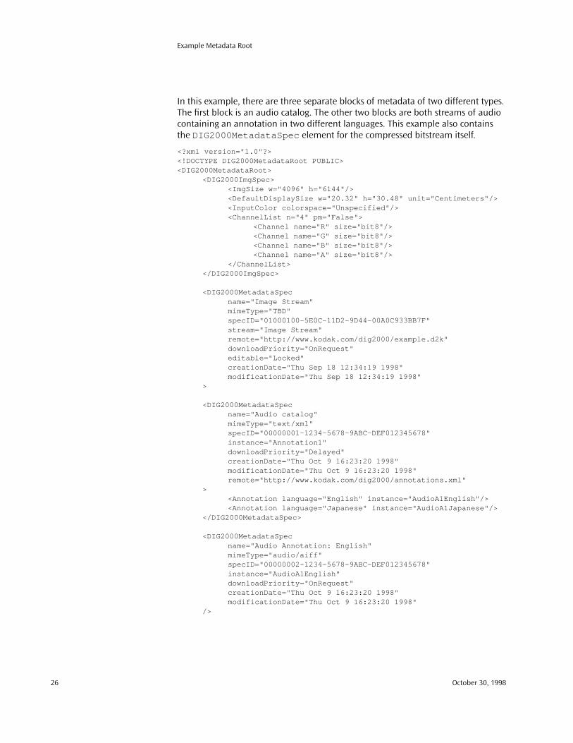
In this example, there are three separate blocks of metadata of two different types. The first block is an audio catalog. The other two blocks are both streams of audio containing an annotation in two different languages. This example also contains the DIG2000MetadataSpec element for the compressed bitstream itself.
<?xml version="1.0"?><!DOCTYPE DIG2000MetadataRoot PUBLIC><DIG2000MetadataRoot>
<DIG2000ImgSpec><ImgSize w="4096" h="6144"/><DefaultDisplaySize w="20.32" h="30.48" unit="Centimeters"/><InputColor colorspace="Unspecified"/><ChannelList n="4" pm="False">
<Channel name="R" size="bit8"/><Channel name="G" size="bit8"/><Channel name="B" size="bit8"/><Channel name="A" size="bit8"/>
</ChannelList></DIG2000ImgSpec>
<DIG2000MetadataSpecname="Image Stream"mimeType="TBD"specID="01000100-5E0C-11D2-9D44-00A0C933BB7F"stream="Image Stream"remote="http://www.kodak.com/dig2000/example.d2k"downloadPriority="OnRequest"editable="Locked"creationDate="Thu Sep 18 12:34:19 1998"modificationDate="Thu Sep 18 12:34:19 1998"
>
<DIG2000MetadataSpecname="Audio catalog"mimeType="text/xml"specID="00000001-1234-5678-9ABC-DEF012345678"instance="Annotation1"downloadPriority="Delayed"creationDate="Thu Oct 9 16:23:20 1998"modificationDate="Thu Oct 9 16:23:20 1998"remote="http://www.kodak.com/dig2000/annotations.xml"
><Annotation language="English" instance="AudioA1English"/><Annotation language="Japanese" instance="AudioA1Japanese"/>
</DIG2000MetadataSpec>
<DIG2000MetadataSpecname="Audio Annotation: English"mimeType="audio/aiff"specID="00000002-1234-5678-9ABC-DEF012345678"instance="AudioA1English"downloadPriority="OnRequest"creationDate="Thu Oct 9 16:23:20 1998"modificationDate="Thu Oct 9 16:23:20 1998"
/>
26 October 30, 1998

DIG2000 file format proposal
<DIG2000MetadataSpecname="Audio Annotation: Japanese"mimeType="audio/aiff"specID="00000002-1234-5678-9ABC-DEF012345678"instance="AudioA1Japanese"downloadPriority="OnRequest"creationDate="Thu Oct 9 16:23:20 1998"modificationDate="Thu Oct 9 16:23:20 1998"
/></DIG2000MetadataRoot>
ISO/IEC JTC1/SG29/WG1 N1017 27


5: Standard metadata fields
It is important for any digital image file format to define a well known set of meta-data fields. Although it is be very beneficial for applications to be able to define new fields, it is essential for good interoperability that the most commonly used fields are defined as part of the standard.
The standard fields are divided into logical blocks that can each exists on their own in a separate stream, each describing a different aspect of the image. The blocks are:
◆ Digital Image Source (Section 5.1)◆ Intellectual Property (Section 5.2)◆ Content Description (Section 5.3)◆ GPS Information (Section 5.4)
The information in these blocks provides the framework to document facts about image capture, intellectual property concerns, and descriptive information about the image itself. With some images, users need to know who is in the picture, where and when it was taken, and so on, to understand the significance of the image.
For instance, a photograph of an automobile accident is useless to an insurance company unless it is known to which accident the picture applies. Similarly, an old family picture is far more interesting if it is known which ancestor is in the picture, and when and where it was taken. One problem with traditional methods of deal-ing with images is that it is easy for this data to become separated from the images, greatly diminishing the value of the images.
A fundamental concept of the DIG2000 format is that an image should be as self-describing as possible. As an image moves across a network, or is written to vari-ous types of media, the self-describing data should move with the image.
Any block may be omitted. If omitted, that block should be treated as if the values are unknown.
Many values specified in this chapter are specified using the standard CDATA repre-sentations of common data types, as specified in Section 4.2.
ISO/IEC JTC1/SG29/WG1 N1017 29

Digital Image Source block
5.1 Digital Image Source block
This block specifies how the digital image samples were determined from original reflected light.
5.1.1 Metadata block structure valuesName: Digital \040 Image \040 SourceMIME type: text/xmlBlock specification ID: 01000500-5E0C-11D2-9D44-00A0C933BB7F
This metadata block may be stored within the DIG2000MetadataSpec element directly, within a stream in the file, or remotely.
5.1.2 Document type definition<?xml version="1.0"?><!DOCTYPE DigitalImageSource [
<!ELEMENT DigitalImageSource((CameraCapture | ScannerCapture | ComputerGenerated)?,Notes?)
><!ATTLIST DigitalImageSource
imageSource (Unidentified | FilmScanner |ReflectionPrintScanner | DigitalCamera |StillFromVideo | ComputerGenerated) "Unidentified"
sceneType (Unidentified | OriginalScene SecondGenerationScene | DigitalSceneGeneration)"Unidentified"
softwareNameAndRelease CDATA #IMPLIEDuserDefinedID CDATA #IMPLIEDsharpnessApproximation CDATA #IMPLIED
>
<!ELEMENT CameraCapture(CameraInformation?, CameraCaptureSettings?,CapturedItem?, Notes?)
>
<!ELEMENT CameraInformation(DigitalCaptureDeviceCharacterization?, Notes?)
><!ATTLIST CameraInformation
manufacturer CDATA #IMPLIEDmodelName CDATA #IMPLIEDserialNumber CDATA #IMPLIED
>
30 October 30, 1998

DIG2000 file format proposal
<!ELEMENT DigitalCaptureDeviceCharacterization(SpatialFrequencyResponse?, CFAPattern?, OECF?, Notes?)
><!ATTLIST DigitalCaptureDeviceCharacterization
sensor (Unidentified | MonochromeArea | OneChipArea |TwoChipColorArea | ThreeChipColorArea |ColorSequentialArea | MonochromeLinear | Trilinear |ColorSequentialLinear) "Unidentified"
focalPlaneXResolution CDATA #IMPLIEDfocalPlaneYResolution CDATA #IMPLIEDfocalPlaneResolutionUnit (Inches | Meters | Centimeters |
Millimeters) "Millimeters"
spectralSensitivity CDATA #IMPLIEDISOSaturationSpeedRating CDATA #IMPLIEDISONoiseSpeedRating CDATA #IMPLIED
>
<!ELEMENT SpatialFrequencyResponse (SFRRow+)><!ELEMENT SFRRow EMPTY><!ATTLIST SFRRow
freq CDATA #REQUIREDhSFR CDATA #REQUIREDvSFR CDATA #REQUIRED
>
<!ELEMENT CFAPattern (CFARow+)><!ELEMENT CFARow
(Red | Green | Blue | Cyan | Magenta | Yellow | White)+><!ELEMENT Red EMPTY><!ELEMENT Green EMPTY><!ELEMENT Blue EMPTY><!ELEMENT Cyan EMPTY><!ELEMENT Magenta EMPTY><!ELEMENT Yellow EMPTY><!ELEMENT White EMPTY>
<!ELEMENT OECF (OECFRow+)><!ELEMENT OECFRow EMPTY><!ATTLIST OECFRow
logExp CDATA #REQUIREDrLevel CDATA #REQUIREDgLevel CDATA #REQUIREDbLevel CDATA #REQUIRED
>
<!ELEMENT CameraCaptureSettings (SpecialEffects?, Notes?)><!ATTLIST CameraCaptureSettings
captureTimeStamp CDATA #IMPLIEDexposureTime CDATA #IMPLIEDfNumber CDATA #IMPLIED
exposureProgram (Unidentified | Manual | ProgramNormal |AperturePriority | ShutterPriority | ProgramCreative |ProgramAction | PortraitMode | LandscapeMode)"Unidentified"
ISO/IEC JTC1/SG29/WG1 N1017 31
Digital Image Source block
brightnessValue CDATA #IMPLIEDbrightnessValueMin CDATA #IMPLIEDbrightnessValueMax CDATA #IMPLIED
exposureBias CDATA #IMPLIED
subjectDistance CDATA #IMPLIEDsubjectDistanceMin CDATA #IMPLIEDsubjectDistanceMax CDATA #IMPLIEDsubjectDistanceUnit (Inches | Meters | Centimeters |
Millimeters) "Meters"
meteringMode (Unidentified | Average |CenterWeightedAverage |Spot | MultiSpot) "Unidentified"
sceneIlluminant (Unidentified | Daylight | FluorescentLight |TungstenLamp | Flash | StandardIlluminantA |StandardIlluminantB | StandardIlluminantC |D55Illuminant | D65Illuminant | D75Illuminant)"Unidentified"
colorTemperature CDATA #IMPLIED
focalLength CDATA #IMPLIEDfocalLengthUnit (Inches | Meters | Centimeters |
Millimeters) "Millimeters"
maxAperture CDATA #IMPLIEDflash (Unidentified | NoFlashUsed | FlashUsed) "Unidentified"flashEnergy CDATA #IMPLIED
flashReturn (Unidentified | SubjectOutsideFlashRange |SubjectInsideFlashRange) "Unidentified"
backLight (Unidentified | FrontLit | BackLit1 | BackLit2)"Unidentified"
subjectLocationX CDATA #IMPLIEDsubjectLocationY CDATA #IMPLIED
exposureIndex CDATA #IMPLIED
autoFocus (Unidentified | AutoFocusUsed |AutoFocusInterrupted | NearFocused | SoftFocused |Manual) "Unidentified"
>
<!ELEMENT SpecialEffects(SpEfUnidentified | SpEfNone | SpEfColored | SpEfDiffusion |SpEfMultiImage | SpEfPolarizing | SpEfSplitField | SpEfStar)+
><!ELEMENT SpEfUnidentified EMPTY><!ELEMENT SpEfNone EMPTY><!ELEMENT SpEfColored EMPTY><!ELEMENT SpEfDiffusion EMPTY><!ELEMENT SpEfMultiImage EMPTY><!ELEMENT SpEfPolarizing EMPTY><!ELEMENT SpEfSplitField EMPTY><!ELEMENT SpEfStar EMPTY>
32 October 30, 1998

DIG2000 file format proposal
<!ELEMENT Notes (#PCDATA)>
<!ELEMENT CapturedItem((OriginalScene | ReflectionPrint | Film | OtherItem)?,Notes?)
>
<!ELEMENT OriginalScene (#PCDATA)>
<!ELEMENT ReflectionPrint (PrintedItem?, Notes?)><!ATTLIST ReflectionPrint
documentSizeX CDATA #IMPLIEDdocumentSizeY CDATA #IMPLIEDdocumentSizeUnit (Inches | Meters | Centimetes |
Millimeters) "Inches"
medium (Unidentified | ContinuousToneImage | HalftoneImage |LineArt) "Unidentified"
type (Unidentified | BlackAndWhitePrint | ColorPrint |BlackAndWhiteDocument | ColorDocument) "Unidentified"
>
<!ELEMENT PrintedItem((Film | ComputerGenerated | OtherItem)?, Notes?)
>
<!ELEMENT Film (CameraCapture?, Notes?)><!ATTLIST Film
brand CDATA #IMPLIEDcategory (Unidentified | NegativeBlackAndWhite |
NegativeColor | ReversalBlackAndWhite | ReversalColor |Chromagenic | InternegativeBlackAndWhite |InternegativeColor) "Unidentified"
filmSizeX CDATA #IMPLIEDfilmSizeY CDATA #IMPLIEDfilmSizeUnit (Inches | meters | Centimetes | Millimeters)
"Inches"
rollID CDATA #IMPLIEDframeID CDATA #IMPLIED
>
<!ELEMENT ComputerGenerated (#PCDATA)><!ATTLIST ComputerGenerated
softwareNameAndRelease CDATA #IMPLIED>
<!ELEMENT OtherItem (#PCDATA)>
<!ELEMENT ScannerCapture(ScannerInformation?, CapturedItem?, Notes?)
>
ISO/IEC JTC1/SG29/WG1 N1017 33

Digital Image Source block
<!ELEMENT ScannerInformation(DigitalCaptureDeviceCharacterization?, Notes?)
><!ATTLIST ScannerInformation
manufacturerName CDATA #IMPLIEDmodelName CDATA #IMPLIEDserialNumber CDATA #IMPLIEDsoftware CDATA #IMPLIEDsoftwareVersion CDATA #IMPLIEDoperatorID CDATA #IMPLIEDcreationTimeStamp CDATA #IMPLIEDmodifiedTimeStamp CDATA #IMPLIEDdevicePixelSize CDATA #IMPLIED
>]>
5.1.3 Element definitions
5.1.3.1 DigitalImageSourceThis element specifies the chain of events that were involved in generating the digi-tal image samples contained in this file from original reflected light. It optionally contains either a CameraCapture (Section 5.1.3.2), ScannerCapture (Section 5.1.3.23) or ComputerGenerated (Section 5.1.3.21) element and a Notes element (Section 5.1.3.15). It has the following attributes:
imageSource. This attribute specifies the device source of the digital file, such as a film scanner, reflection print scanner, or digital camera.
sceneType. This attribute specifies the type of scene that was captured by the device that produced the digital image samples in this file. It differentiates “origi-nal scenes” (direct capture of real-world scenes) from “second generation scenes” (images captured from pre-existing hardcopy images). It provides further differenti-ation for scenes that are digitally composed.
softwareNameAndRelease. This attribute specifies the name of the software, its manufacturer’s name, and the version of the software used to create the DIG2000 image.
userDefinedID. This attribute specifies an ID code assigned to an image by the user. This attribute is useful when users have their own filing or accounting scheme with an identification system already in place, and enables users to cross-reference their digital files to a pre-existing analog one.
sharpnessApproximation. To perform image filtering in a resolution indepen-dent manner, the algorithm must have information on the degree of blurring introduced by the system components which generated the digital image (digital camera, scanner, etc.). This is expressed as the effective filter width, q. Approxi-mate the total capture MTF by the form, where q is the width and s is the spatial frequency measured in cycles per pixel at the captured resolution delivered by the input device. If the MTF is far from Gaussian form, fit the low-frequency portion best. This attribute specifies the value q.
34 October 30, 1998

DIG2000 file format proposal
5.1.3.2 CameraCaptureThis element specifies a camera capture of a scene. It optionally contains a Cam-eraInformation (Section 5.1.3.3), CameraCaptureSettings (Section 5.1.3.12) and CapturedItem element (Section 5.1.3.16) and a Notes element (Section 5.1.3.15), but has no attributes.
5.1.3.3 CameraInformationThis element specifies information about that camera that captured the scene. It optionally contains a DigitalCaptureDeviceCharacterization element (Section 5.1.3.4) and a Notes element (Section 5.1.3.15), and has the following attributes:
manufacturerName. This attribute specifies the name of the manufacturer or vendor of the camera or original-scene capture device.
modelName. This attribute specifies the model name or number of the camera, and can include the serial number of the camera.
serialNumber. This attribute specifies the manufacturer’s serial number of the camera, encoded as a text string.
5.1.3.4 DigitalCaptureDeviceCharacterizationThis element specifies the technical characterization of the digital capture device. It optionally contains a SpatialFrequencyResponse (Section 5.1.3.5), CFAPat-tern (Section 5.1.3.7), OECF (Section 5.1.3.10) and Notes element (Section 5.1.3.15), and has the following attributes:
sensor. This attribute specifies the type of image sensor used in the camera or image capturing device.
focalPlaneXResolution, focalPlaneYResolution. These attributes specify the number of pixels per focalPlaneResolutionUnit in the X and Y direc-tions for the main image respectively. They specify the actual focal plane X and Y resolutions at the focal plane of the camera. These values must be valid Reals.
focalPlaneResolutionUnit. This attributes encodes the unit of measurement for the focalPlaneXResolution and focalPlaneXResolution attributes.
spectralSensitivity. This attribute can be used to describe the spectral sensitivity of each channel of the camera used to capture the image. It is useful for certain sci-entific applications. The string is compatible with the New Standard Practice for the Electronic Interchange of Color and Appearance Data being developed within an ASTM Technical Committee. The string consists of a mandatory keyword list fol-lowed by the associated data values. Mandatory keywords include NUMBER_OF_FIELDS, which equals the number of channels (spectral bands) + 1, and NUMBER_OF_SETS, which specifies the number of spectral frequency (wave-length) entries.
ISO/IEC JTC1/SG29/WG1 N1017 35

Digital Image Source block
ISOSaturationSpeedRating. This attribute specifies the ISO saturation speed rating classification as defined in [4]. The value of this attribute is encoded as a Real.
ISONoiseSpeedRating. This attribute specifies the iso noise-based speed rating classification as defined in [4]. The value of this attribute is encoded as a Real.
5.1.3.5 SpatialFrequencyResponseThis element specifies the spatial frequency response (SFR) of image capturing device. It consists of an ordered list of SFRRow elements containing attributes that specify an array of values, but has no attributes itself. One instance of the SFRRow element (Section 5.1.3.6) specifies one point on the frequency response curve. The device measured SFR data, described in [5], can be stored as a table of spatial fre-quencies, horizontal SFR values, vertical SFR values, and diagonal SFR values. The following is a simple example of measured SFR data encoded using the XML nota-tion (freq in lw/ph).
<SpatialFrequencyResponse><SFRRow freq="0.1" hSFR="1.00" vSFR="1.00"/><SFRRow freq="0.2" hSFR="0.90" vSFR="0.95"/><SFRRow freq="0.3" hSFR="0.80" vSFR="0.85"/>
</SpatialFrequencyResponse>
5.1.3.6 SFRRowThis element specifies a single point in the SFR curve of the image capturing device. It contains no elements, but has the following attributes:
freq, hSFR, vSFR. These attributes encode the spatial frequency response (SFR) of the camera or image capturing device at a single frequency.
5.1.3.7 CFAPatternEncodes the actual color filter array (CFA) geometric pattern of the image sensor used to capture a single-sensor color image. It is not relevant for all sensing meth-ods. The data contains the minimum number of rows and columns of filter color values that uniquely specify the color filter array. This element contains CFARow elements (Section 5.1.3.8), one for each row in the CFA pattern. The following is a sample encoding using the XML syntax:
<CFAPattern><CFARow><Green/><Red/> <Green/><Red/> <Green/><Red/> </CFARow><CFARow><Blue/> <Green/><Blue/> <Green/><Blue/> <Green/></CFARow><CFARow><Green/><Red/> <Green/><Red/> <Green/><Red/> </CFARow><CFARow><Blue/> <Green/><Blue/> <Green/><Blue/> <Green/></CFARow>
</CFAPattern>
5.1.3.8 CFARowThis element specifies one row of a CFA pattern. It contains Red, Green , Blue , Cyan, Magenta , Yellow and White elements (Section 5.1.3.9), and has no attributes.
36 October 30, 1998

DIG2000 file format proposal
5.1.3.9 Red, Green, Blue, Cyan, Magenta, Yellow, WhiteThese elements specify one filter array element in a CFA pattern. These elements have no contents and no attributes.
5.1.3.10 OECFThis element specifies the opto-electronic conversion function (OECF). The OECF is the relationship between the optical input and the image file code value outputs of an electronic camera. The property allows OECF values defined in [6] to be stored as a table of values. The following example shows a simple example of measured OECF data.
<OECF><OECFRow logexp="-3.0" rlevel="10.2" glevel="12.5" blevel="8.9"/><OECFRow logexp="-2.0" rlevel="48.1" glevel="47.5" blevel="48.3"/><OECFRow logexp="-1.0" rlevel="150.2" glevel="152.0"
blevel="149.8"/></OECF >
This element contains one or more OECFRow elements (Section 5.1.3.11), and has no attributes.
5.1.3.11 OECFRowThis element specifies one point of the opto-electronic conversion function (OECF). It has no contents, but has the following attributes:
logExp. This attribute specifies the log exposure value for this point in the OECF. The value must be encoded as a Real.
rLevel. This attribute specifies the red level for this point in the OECF. The value must be encoded as a Real.
gLevel. This attribute specifies the green level for this point in the OECF. The value must be encoded as a Real.
bLevel. This attribute specifies the blue level for this point in the OECF. The value must be encoded as a Real.
5.1.3.12 CameraCaptureSettingsThis element describes the camera settings used when the image was captured. New generations of digital and film cameras make it possible to capture more information about the conditions under which a picture was taken. This may include information about the lens aperture and exposure time, whether a flash was used, which lens was used, etc. This technical information is useful to profes-sional and serious amateur photographers. In addition, some of these properties are useful to image database applications for populating values useful to image analysis and retrieval. This element optionally contains a SpecialEffects (Section 5.1.3.13) and Notes element (Section 5.1.3.15), and has the following attributes.
ISO/IEC JTC1/SG29/WG1 N1017 37

Digital Image Source block
captureTimeStamp. This attribute specifies the date and time the image was captured. The value of this attribute must be a Timestamp.
exposureTime. This attribute specifies the exposure time used when the image was captured. The units are seconds. The value of this attribute must be a Real.
fNumber. This attribute specifies the lens f-number (ratio of lens aperture to focal length) used when the image was captured. The value of this attribute must be a Real.
exposureProgram. This attribute specifies the class of exposure program that the camera used at the time the image was captured. Note the following standard definitions for the following program modes:
◆ ProgramNormal is a general purpose auto-exposure
◆ AperturePriority means that the user selected the aperture and the camera selected the shutter speed for proper exposure
◆ ShutterPriority means that the user selected the shutter speed and the camera selected the aperture for proper exposure
◆ ProgramCreative is biased toward greater depth of field
◆ ProgramAction is biased toward faster shutter speed
◆ PortraitMode is intended for close-up photos with the background out of focus
◆ LandscapeMode is intended for landscapes with the background in good focus
brightnessValue. This attribute specifies the Brightness Value (BV) measured when the image was captured, using APEX units. The expected maximum value is approximately 13.00 corresponding to a picture taken of a snow scene on a sunny day, and the expected minimum value is approximately –3.00 corresponding to a night scene. The value of this attribute must be a Real.
brightnessValueMin, brightnessValueMax. If the value supplied by the cap-ture device represents a range of values rather than a single value, the brightnessValueMin and brightnessValueMax attributes specify the lower and upper values of the range, respectively. The values of these attributes must be Reals.
exposureBias. This attribute specifies the actual exposure bias (the amount of over or under-exposure relative to a normal exposure, as determined by the cam-era’s exposure system) used when capturing the image, using APEX units. The range is between –99.99 and 99.99. The value is the number of exposure values (stops). For example, –1.00 indicates 1 eV (1 stop) underexposure, or half the normal expo-sure. The value of this attribute must be a Real.
38 October 30, 1998

DIG2000 file format proposal
subjectDistance. This attribute specifies the distance (in the unit specified by the subjectDistanceUnit attribute) between the front nodal plane of the lens and the position at which the camera was focusing when the image was captured. Note that the camera may have focused on a subject within the scene which may not have been the primary subject. The value of this attribute must be a Real.
subjectDistanceMin, subjectDistanceMax. If the value supplied by the cap-ture device represents a range of values rather than a single value, the subjectDistanceMin and subjectDistanceMax attributes specify the lower and upper values of the range, respectively, the unit specified by the sub-jectDistanceUnit attribute. The values of these attributes must be Reals.
subjectDistanceUnit. This attributes encodes the unit of measurement for the subjectDistance , subjectDistanceMin and subjectDistanceMax attributes.
meteringMode. This attribute specifies the metering mode (the camera’s method of spatially weighting the scene luminance values to determine the sensor exposure) used when capturing the image.
sceneIlluminant. This attribute specifies the light source (scene illuminant) that was present when the image was captured.
colorTemperature. This attribute specifies the actual color temperature value of the scene illuminant stored in units of Kelvin. Color temperatures are limited to values in the range of 0 to 32767 Kelvin. The value of this attribute must be a Real.
focalLength. This attribute specifies the lens focal length (in the unit specified by the focalLengthUnit attribute) used to capture the image. The value of this attribute must be a Real.
focalLengthUnit. This attributes encodes the unit of measurement for the focalLength attribute.
maxAperture. This attribute specifies the maximum possible aperture opening (minimum lens f-number) of the camera or image capturing device, using APEX units. The allowed range is 1.00 to 99.99. The value of this attribute must be a Real.
flash. This attribute specifies whether flash was used.
flashEnergy. This attribute specifies the amount of flash energy that was used. The measurement units are Beam Candle Power Seconds (BCPS). The value of this attribute must be a Real.
flashReturn. This attribute specifies whether the camera judged that the flash was not effective at the time of exposure.
backLight. This attribute specifies the camera's evaluation of the lighting condi-tions at the time of exposure. Note the following definitions for lighting situations:
ISO/IEC JTC1/SG29/WG1 N1017 39
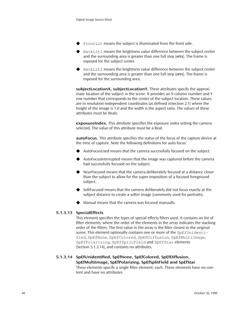
Digital Image Source block
◆ FrontLit means the subject is illuminated from the front side.
◆ BackLit1 means the brightness value difference between the subject center and the surrounding area is greater than one full step (APEX). The frame is exposed for the subject center.
◆ BackLit2 means the brightness value difference between the subject center and the surrounding area is greater than one full step (APEX). The frame is exposed for the surrounding area.
subjectLocationX, subjectLocationY. These attributes specify the approxi-mate location of the subject in the scene. It provides an X column number and Y row number that corresponds to the center of the subject location. These values are in resolution-independent coordinates (as defined inSection 2.1) where the height of the image is 1.0 and the width is the aspect ratio. The values of these attributes must be Reals.
exposureIndex. This attribute specifies the exposure index setting the camera selected. The value of this attribute must be a Real.
autoFocus. This attribute specifies the status of the focus of the capture device at the time of capture. Note the following definitions for auto focus:
◆ AutoFocusUsed means that the camera successfully focused on the subject.
◆ AutoFocusInterrupted means that the image was captured before the camera had successfully focused on the subject.
◆ NearFocused means that the camera deliberately focused at a distance closer than the subject to allow for the super-imposition of a focused foreground subject.
◆ SoftFocused means that the camera deliberately did not focus exactly at the subject distance to create a softer image (commonly used for portraits).
◆ Manual means that the camera was focused manually
5.1.3.13 SpecialEffectsThis element specifies the types of special effects filters used. It contains an list of filter elements, where the order of the elements in the array indicates the stacking order of the filters. The first value in the array is the filter closest to the original scene. This element optionally contains one or more of the SpEfUnidenti-fied , SpEfNone , SpEfColored , SpEfDiffusion , SpEfMultiImage , SpEfPolarizing , SpEfSplitField and SpEfStar elements (Section 5.1.3.14), and contains no attributes.
5.1.3.14 SpEfUnidentified, SpEfNone, SpEfColored, SpEfDiffusion, SpEfMultiImage, SpEfPolarizing, SpEfSplitField and SpEfStarThese elements specify a single filter element, each. These elements have no con-tent and have no attributes.
40 October 30, 1998

DIG2000 file format proposal
5.1.3.15 NotesThis element contains additional information not provided by the other proper-ties. Both professional and amateur photographers may want to keep track of a variety of miscellaneous technical information, such as the use of extension tubes, bellows, close-up lenses, and other specialized accessories.
5.1.3.16 CapturedItemThis element contains a description of the item that was digitally captured. For example, if the capture device is a film scanner, this element specifies information about the piece of film that was scanned. This element contains either an Origi-nalScene (Section 5.1.3.17), ReflectionPrint (Section 5.1.3.18), Film (Section 5.1.3.20) or OtherItem element (Section 5.1.3.22) and a Notes element (Section 5.1.3.15), and has no attributes.
5.1.3.17 OriginalSceneThis element contains a description of the original scene. It contains text describ-ing the scene, but has no attributes.
5.1.3.18 ReflectionPrintThis element contains information about a reflection print that was digitally cap-tured. It optionally contains a PrintedItem (Section 5.1.3.19) and a Notes element (Section 5.1.3.15), which describes what was used to create this reflection print, and has the following attributes:
documentSizeX, documentSizeY. These attributes specify the lengths of the X and Y dimension of the original photograph or document, respectively. The values of these attribute must be encoded as Reals, and are given in the unit of measure specified by the documentSizeUnit attribute.
documentSizeUnit. This attribute specifies the measurement units in which the documentSizeX and documentSizeY attributes are specified.
medium. This attribute specifies the medium of the original photograph, docu-ment, or artifact.
type. This attribute specifies the type of the original document or photographic print.
5.1.3.19 PrintedItemThis attribute contains a description of the item that was printed. It either contains a Film (Section 5.1.3.20), ComputerGenerated (Section 5.1.3.21), or Other-Item (Section 5.1.3.22) element and a Notes element (Section 5.1.3.15), and has no attributes.
5.1.3.20 FilmThis attribute contains a description of a piece of film that was digitized. It option-ally contains a CameraCapture element (Section 5.1.3.2) and a Notes element
ISO/IEC JTC1/SG29/WG1 N1017 41

Digital Image Source block
(Section 5.1.3.15), indicating how the image on the film was captured, and has the following attributes:
brand. This element specifies the name of the film manufacturer, the brand name, product code and generation code (for example, Acme Bronze 100, Acme Aerial 100).
category. This attribute specifies the category of film used. Note: The category Chromagenic refers to B/W negative film that is developed with a C41 process (i.e., color negative chemistry).
filmSizeX, filmSizeY. These attributes specify the size of the X and Y dimension of the film used, and the unit of measurement. The values of these elements must be encoded as Reals.
filmSizeUnits. This attribute specifies the unit of measure in which the film-SizeX and filmSizeY attribute are specified.
rollID. This attribute specifies the roll number or ID of the film. For some film, this number is encoded on the film cartridge as a bar code.
frameID. This attribute specifies the frame number or ID of the frame digitized from the roll of film.
5.1.3.21 ComputerGeneratedThis element contains information about the creation of a computer generated dig-ital image. The element has the following attributes:
softwareNameAndRelease. This attribute specifies the name of the software, its manufacturer’s name, and the version of the software used to create the image.
5.1.3.22 OtherItemThis element contains information about an item that was digitized that is not a ComputerGenerated (Section 5.1.3.21), Film (Section 5.1.3.20), Reflection-Print (Section 5.1.3.18), or OriginalScene (Section 5.1.3.17). It has no attributes.
5.1.3.23 ScannerCaptureThis element contains information about a scanner capture of an item. It option-ally contains a ScannerInformation (Section 5.1.3.24) and CapturedItem elements (Section 5.1.3.16) and a Notes element (Section 5.1.3.15), but has no attributes.
5.1.3.24 ScannerInformationThis element contains information about a particular scanner that was used to digi-tize an image item. It optionally contains a DigitalCaptureDevice-Characterization (Section 5.1.3.4) element and a Notes element (Section 5.1.3.15), and has the following attributes:
42 October 30, 1998

DIG2000 file format proposal
manufacturerName. This attribute specifies the manufacturer or vendor of the scanner.
modelName. This attribute specifies model name or number of the scanner. It can also include the serial number of the scanner.
serialNumber. This attribute specifies the manufacturer’s serial number of the scanner as a text string.
software. This attribute specifies the name and version of the scanner software or firmware.
softwareVersion. This attribute specifies the version number or revision date of the scanner software or firmware. If the value of this attribute is a date, it must be encoded as a Timestamp.
serviceBureau. This attribute specifies the name of the service bureau, photofin-isher, or organization performing the scan.
operatorID. This attribute specifies a name or ID for the person operating the scanner.
creationTimeStamp. This attribute specifies the date and time the image was scanned item was digitized. This attribute should never be changed after it is writ-ten in the image capture device. The value of this attribute must be a Timestamp.
pixelSize. This attribute specifies the pixel size, in micrometers, of the scanner. The value of this attribute must be encoded as a Real.
5.1.4 Examples
5.1.4.1 A simple DigitalImageSource<?xml version="1.0"><!DOCTYPE DigitalImageSource PUBLIC><DigitalImageSource
imageSource="DigitalCamera"sceneType="OriginalScene"
><CameraCapture>
<CameraInformationmanufacturer="Acme Camera Company"modelName="RZ55L"serialNumber="123-456-789"
/>
ISO/IEC JTC1/SG29/WG1 N1017 43

Digital Image Source block
<CameraCaptureSettingscaptureTimeStamp="Tue, 20 Oct 1998 17:42:12 -0400"fNumber="1.0"exposureProgram="ProgramAction"subjectDistance="3"subjectDistanceUnit="Meters"meteringMode="CenterWeightedAverage"sceneIlluminant="Daylight"focalLength="50"focalLengthUnit="Millimeters"flash="NoFlashUsed"autoFocus="AutoFocusUsed"
/>
<CapturedItem><OriginalScene>Petroglyph on the Big Island of Hawaii</OriginalScene>
</CapturedItem></CameraCapture>
</DigitalImageSource>
5.1.4.2 A complex DigitalImageSource<?xml version="1.0"><!DOCTYPE DigitalImageSource PUBLIC><DigitalImageSource
imageSource="FilmScanner"sceneType="SecondGenerationScene"
><ScannerCapture>
<ScannerInformationmanufacturerName="Acme Scanner Company"modelName="Flatbed 40"serialNumber="987-654-321"software="Acme ScanThatSlide"softwareVersion="5.3"creationTimeStamp="Tue, 20 Oct 1998 17:42:12 -0400"
/>
<CapturedItem><Film
brand="Acme Film Company"category="InternegativeColor"filmSizeX="6"filmSizeY="6"filmSizeUnit="Centimeters"rollID="27845"frameID="12A"
><CameraCapture>
<CameraInformationmanufacturerName="Acme Camera Company"modelName="Dupe camera 29"serialNumber="18"
/>
44 October 30, 1998

DIG2000 file format proposal
<CapturedItem><Film
brand="Acme Film Company"category="ColorNegative"filmSizeX="6"filmSizeY="6"filmSizeUnit="Centimeters"rollID="24563"frameID="8"
><CameraCapture>
<CameraInformation>mamufacturerName="Ace"modelName="SnapShot"serialNumber="SS-35"
/>
<CapturedItem><OriginalScene>
Petroglyph on the Big Island of Hawaii</OriginalScene></CapturedItem>
</CameraCapture></Film>
</CapturedItem></CameraCapture>
</Film></CapturedItem>
</ScannerCapture></DigitalImageSource>
5.2 Intellectual Property block
The intellectual property block contains information about the ownership and copyright status of the image. Rights for an original artifact may be stated, along with the rights for the digital file.
5.2.1 Metadata block structure valuesName: Intellectual \040 PropertyMIME type: text/xmlBlock specification ID: 01000200-5E0C-11D2-9D44-00A0C933BB7F
This metadata block may be stored within the DIG2000MetadataSpec element directly, within a stream in the file, or remotely.
5.2.2 Document type definition<?xml version="1.0"?><!DOCTYPE IntellectualProperty [
<!ELEMENT IntellectualProperty (Copyright?, Notes?)><!ATTLIST IntellectualProperty
originalImageLegalBroker CDATA #IMPLIEDdigitalImageLegalBroker CDATA #IMPLIEDauthorship CDATA #IMPLIED
>
ISO/IEC JTC1/SG29/WG1 N1017 45

Intellectual Property block
<!ELEMENT Copyright (#PCDATA)><!ELEMENT Pricing (#PCDATA)><!ELEMENT Notes (#PCDATA)>
]>
5.2.3 Element definitions
5.2.3.1 IntellectualProperty elementThe intellectualProperty element optionally contains one of each of the Copyright (Section 5.2.3.2), Pricing (Section 5.2.3.3) and Notes elements (Section 5.2.3.4). It also has the following attributes:
originalImageLegalBroker. This attribute specifies the name of the person or organization that holds the legal right to grant permissions or restrict use of the original image. The original image is either the analog source scanned to create the digital file or the original digital capture of a scene.
digitalImageLegalBroker. This attribute specifies the name of the person or organization that holds the legal right to grant permissions or restrict use of the digital file.
authorship. This attribute specifies the name of the camera owner, photogra-pher or image creator.
5.2.3.2 CopyrightThis element encodes the copyright notice of the Legal Broker for the digital file. The complete copyright statement should be contained in this element, including any dates and statements of claims. If desired, this element can also list details concerning the Legal Broker.
5.2.3.3 PricingThis element specifies pricing information for this image. It contains a textual description of the pricing.
5.2.3.4 NotesThis element encodes additional information beyond the scope of other properties in this block.
5.2.4 Example<?xml version="1.0"?><!DOCTYPE IntellectualProperty PUBLIC><IntellectualProperty
originalImageLegalBroker="John Doe"digitalImageLegalBroker="Acme Stock Photography, Inc."
><Copyright>1998, All rights reserved</Copyright><Pricing>Available for commercial use for per use fee of $100 US</Pricing<Notes>[email protected], 555-555-1234</Notes>
</IntellectualProperty>
46 October 30, 1998

DIG2000 file format proposal
5.2.5 Intellectual property issuesIt is important for developers to understand the implications of intellectual prop-erty and copyright information on actions taken by end users when creating derivative works of copyrighted material:
Rights are based on the user and creator. Rights to use the original digital image are based on both the identity of the user and the permissions and restric-tions imposed on the image itself by the creator. One user in one situation will most certainly have been granted different rights than another user in the same or a different situation. For example, some photographers will not allow their images to be sold for billboard display and the rights to some images are granted exclu-sively to particular individuals.
Rights are fluid. Rights are often quite fluid and may change over time. The rights an individual has today may not be the same as the rights that user will have tomorrow. Thus although a DIG2000 file can contain a statement of rights, it often cannot be a complete statement.
An end-user doesn’t have all rights. An end-user generally only has particu-lar rights. For example, a user may have the right to use the original digital image in its entirety but not the right to produce a derivative work from that original digi-tal image.
Rights claimed for the original. It is also important to understand the rights potentially claimed for the original digital image or original work. Regardless of the actions taken by the end user, the original copyright and particular rights granted to the end user for the original are still in effect. Although the end user may be able to claim a copyright on the new derived work, the portion of the original that is used in the derived work is still covered by the original copyright.
For example, an end user adjusts the color balance of the original image, produc-ing a new derived work. Provided that user did have the right to produce the new work, the user may only claim a copyright on the derived part of that work. In this example, only the color balance adjustment and the fact that it was performed on a particular original digital image may be copyrighted. In addition, the user may still not have the right to even display the new work. In order to display the new work, the user must have the right to display the original digital image.
Although it is important for developers to understand the implications of intellec-tual property, it is generally not possible for an application to determine the rights of a particular individual at a particular time and to act on those rights. However, it is possible for applications to aid end users in reducing their liability for violation of copyright on the original digital images. Applications can provide this functionality by:
◆ Stating the terms of the copyright for the new derived work◆ Embedding the original copyright within the attribution for the derived work◆ Indicating the scope of the changes from the original to the derived work.
ISO/IEC JTC1/SG29/WG1 N1017 47
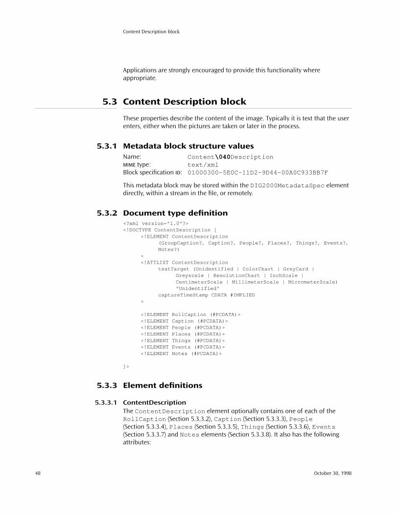
Content Description block
Applications are strongly encouraged to provide this functionality where appropriate.
5.3 Content Description block
These properties describe the content of the image. Typically it is text that the user enters, either when the pictures are taken or later in the process.
5.3.1 Metadata block structure valuesName: Content \040 DescriptionMIME type: text/xmlBlock specification ID: 01000300-5E0C-11D2-9D44-00A0C933BB7F
This metadata block may be stored within the DIG2000MetadataSpec element directly, within a stream in the file, or remotely.
5.3.2 Document type definition<?xml version="1.0"?><!DOCTYPE ContentDescription [
<!ELEMENT ContentDescription(GroupCaption?, Caption?, People?, Places?, Things?, Events?,Notes?)
><!ATTLIST ContentDescription
testTarget (Unidentified | ColorChart | GreyCard |Greyscale | ResolutionChart | InchScale |CentimeterScale | MillimeterScale | M icrometerScale)"Unidentified"
captureTimeStamp CDATA #IMPLIED>
<!ELEMENT RollCaption (#PCDATA)><!ELEMENT Caption (#PCDATA)><!ELEMENT People (#PCDATA)><!ELEMENT Places (#PCDATA)><!ELEMENT Things (#PCDATA)><!ELEMENT Events (#PCDATA)><!ELEMENT Notes (#PCDATA)>
]>
5.3.3 Element definitions
5.3.3.1 ContentDescriptionThe ContentDescription element optionally contains one of each of the RollCaption (Section 5.3.3.2), Caption (Section 5.3.3.3), People (Section 5.3.3.4), Places (Section 5.3.3.5), Things (Section 5.3.3.6), Events (Section 5.3.3.7) and Notes elements (Section 5.3.3.8). It also has the following attributes:
48 October 30, 1998

DIG2000 file format proposal
testTarget. This attribute specifies information about the type of scale or test tar-get that is captured within the image frame.
captureTimeStamp. This attribute specifies the date and time the image was originally captured. In the case of a scanned photograph, this would be the date and time of the original photograph, not the date and time it was scanned. In the case of other printed materials, this would be the date the item was originally pub-lished. This attribute must be a valid Timestamp.
5.3.3.2 RollCaptionThis element contains text that describes the subject or purpose of a group or roll of images (e.g., a roll of film). The image in the digital file is one member of the “roll.”
5.3.3.3 CaptionThis element contains text that describes the subject or purpose of the image. It may be additionally used to provide any other type of information related to the image.
5.3.3.4 PeopleThis element contains text that specifies the personal or “role” names of people in the image. Personal names are any variation of FirstName, Initial, LastName, Titles of Address denotations (for example, Dr. Jane Smith). Roles may be occupational or situational denotations (for example, doctor). Multiple entries are allowed.
5.3.3.5 PlacesThis element contains text that specifies the place depicted in the image (Chicago, Illinois). Multiple entries are allowed (e.g., the image may contain a map or an aerial view of a region).
5.3.3.6 ThingsThis element contains text that specifies the names of tangible objects depicted in the image (Washington Monument, for example). Multiple entries are allowed.
5.3.3.7 EventsThis element contains text that specifies the events depicted in the image. Events may be personal or societal (e.g., birthday, anniversary, New Year’s Eve). Editorial applications may use this property to describe historical, political, or natural events (e.g., a coronation, the Crimean War, Hurricane Andrew).
5.3.3.8 NotesThis element contains additional user/application defined information beyond the scope of other properties in this block.
ISO/IEC JTC1/SG29/WG1 N1017 49
GPS Information block
5.3.4 Example<?xml version="1.0"?><!DOCTYPE ContentDescription PUBLIC><ContentDescription
testTarget="GreyCard"captureTimeStamp="Tue, 20 Oct 1998 17:42:12 -0400"
><RollCaption>My trip to Hawaii</RollCaption><Caption>A petroglyph of a sea turtle</Caption><Places>Hawaii Volcanos National Park</Places>
</ContentDescription>
5.4 GPS Information block
This block of properties is used store information describing where the original scene was captured, in terms of the Global Position System.
5.4.1 Metadata block structure valuesName: Capture \040 Location \040 (GPS)MIME type: text/xmlBlock specification ID: 01000400-5E0C-11D2-9D44-00A0C933BB7F
This metadata block may be stored within the DIG2000MetadataSpec element directly, within a stream in the file, or remotely.
5.4.2 Document type definition<?xml version="1.0"?><!DOCTYPE GPSInformation [
<!ELEMENT GPSInformation EMPTY><!ATTLIST GPSInformation
GPSVersionID CDATA #REQUIREDGPSLatitudeRef (North | South) #REQUIREDGPSLatitude CDATA #REQUIREDGPSLongitudeRef (East | West) #REQUIREDGPSLongitude CDATA #REQUIREDGPSAltitudeRef CDATA “0"GPSAltitude CDATA #REQUIREDGPSTimeStamp CDATA #REQUIREDGPSSatellites CDATA #IMPLIEDGPSStatus (InProgress | Interrupted) #REQUIRED
GPSMeasureMode (TwoDimensional | ThreeDimensional)"TwoDimensional"
GPSDOP CDATA #REQUIRED
GPSSpeedRef (MilesPerHour | KilometersPerHour | Knots)"MilesPerHour"
GPSSpeed CDATA #IMPLIEDGPSTrackRef (True | Magnetic) "True"GPSTrack CDATA #IMPLIEDGPSImgDirectionRef (True | Magnetic) "True"
50 October 30, 1998
DIG2000 file format proposal
GPSImgDirection CDATA #IMPLIEDGPSMapDatum CDATA #IMPLIEDGPSDestLatitudeRef (North | South) "North"GPSDestLatitude CDATA #IMPLIEDGPSDestLongitudeRef (East | West) "East"GPSDestLongitude CDATA #IMPLIEDGPSDestBearingRef (True | Magnetic) "True"GPSDestBearing CDATA #IMPLIEDGPSDestDistanceRef (Miles | Kilometers | Knots) "Miles"GPSDestDistance CDATA #IMPLIED
>]>
5.4.3 Element descriptions
5.4.3.1 GPSInformationThe GPSinformation element contains no content, but has the following attributes:
GPSVersionID. This attribute specifies the version of GPSInfoIFD . The value of this attribute must be 2.0.0.0 .
GPSLatitudeRef. This attribute specifies whether the latitude is north or south latitude.
GPSLatitude. This attribute specifies the numerical latitude. The latitude is expressed as three floating values giving the degrees, minutes, and seconds, respec-tively. When degrees, minutes and seconds are expressed, the format is dd/1, mm/1, ss /1 . When degrees and minutes are used and, for example, frac-tions of minutes are given up to two decimal places, the format is dd/1, mmmm/100,0/1 .
GPSLongitudeRef. This attribute specifies whether the longitude is east or west longitude.
GPSLongitude. This attribute specifies the numerical longitude. The longitude is expressed in the same format as the GPSLatitude attribute.
GPSAltitudeRef. This attribute specifies the altitude used as the reference alti-tude. In this version the reference altitude is sea level, so this tag must be set to 0, and encoded as an Real. The reference unit is meters.
GPSAltitude. This attribute specifies the altitude based on the reference in the GPSAltitudeRef attribute. Altitude is expressed as one floating value, and must be encoded as a Real. The reference unit is meters.
GPSTimeStamp. This attribute specifies the time of position capture as UTC (Coor-dinated Universal Time). The value of this attribute is encoded as a string containing three Real values, with the values separated by a colon. The three val-
ISO/IEC JTC1/SG29/WG1 N1017 51

GPS Information block
ues represent the hour, minute, and second. For example, if the time is 4:58:19 PM, then the value of this field would be 16:58:19 .
GPSSatellites. This attribute specifies the GPS satellites used for measurements. This tag can be used to describe the number of satellites, their ID number, angle of elevation, azimuth, SNR and other information in ASCII notation. The format is not specified. If the GPS receiver is incapable of taking measurements, value of the tag must be set to NULL.
GPSStatus. This attribute specifies the status of the GPS receiver when the image is recorded.
GPSMeasureMode. This attribute specifies the GPS measurement mode.
GPSDOP. This attribute specifies the GPS DOP (data degree of precision). An HDOP value is written during two-dimensional measurement, and PDOP during three-dimensional measurement. The value of this attribute must be a Real.
GPSSpeedRef. This attribute specifies the unit used to express the GPS receiver speed of movement.
GPSSpeed. This attribute specifies the speed of GPS receiver movement. The value of this attribute must be a Real.
GPSTrackRef. This attribute specifies the reference for giving the direction of GPS receiver movement.
GPSTrack. This attribute specifies the direction of GPS receiver movement. The value of this attribute must be a Real. The range of values is from 0.00 to 359.99.
GPSImgDirectionRef. This attribute specifies the reference for giving the direc-tion of the image when it is captured.
GPSImgDirection. This attribute specifies the direction of the image when it was captured. The value of this attribute must be a Real. The range of values is from 0.00 to 359.99.
GPSMapDatum. This attribute specifies the geodetic survey data used by the GPS receiver. If the survey data is restricted to Japan, the value of this tag is TOKYO or WGS-84. If a GPS Info tag is recorded, it is strongly recommended that this tag be recorded.
GPSDestLatitudeRef. This attribute specifies whether the latitude of the destina-tion point is north or south latitude.
GPSDestLatitude. This attribute specifies the latitude of the destination point. The latitude is expressed in the same format as the GPSLatitude attribute.
52 October 30, 1998

DIG2000 file format proposal
GPSDestLongitudeRef. This attribute specifies whether the longitude of the des-tination point is east or west longitude.
GPSDestLongitude. This attribute specifies the longitude of the destination point. The longitude is expressed in the same format as the GPSLatitude attribute.
GPSDestBearingRef. This attribute specifies the reference used for giving the bearing to the destination point.
GPSDestBearing. This attribute specifies the bearing to the destination point. The value of this attribute must be a Real. The range of values is from 0.00 to 359.99.
GPSDestDistanceRef. This attribute specifies the units used to express the dis-tance to the destination point.
GPSDestDistance. This attribute specifies the distance to the destination point. The value of this attribute must be a Real.
5.4.4 Example<?xml version="1.0"?><!DOCTYPE GPSinformation PUBLIC><GPSInformation
GPSVersionID="2.0.0.0"GPSLatitudeRef="North"GPSLatitude="21/1,19/1,0/1"GPSLongitudeRef="West"GPSLatitude="157/1,52/1,0/1"GPSAltitudeRef="0"GPSAltitude="365"GPSTimeStamp="17:42:12"GPSStatus="InProgress"GPSDOP="1.0"
</GPSInformation>
ISO/IEC JTC1/SG29/WG1 N1017 53


6: Color representation
This chapter describes how the colorspace of uncompressed data is specified and how that color information should be interpreted when loading and processing the image.
6.1 Introduction
The method of encoding for color imagery is critical to how consistently the colors in an image will be reproduced across different systems and different media types. The DIG2000 proposal format defines sRGB as the single default colorspace and sup-port for International Color Consortium (ICC) color profiles.
The sRGB colorspace is an international standard (IEC 61966–2–1) that represents color appearance with respect to a defined reference viewing environment, display and observer. For color stimuli that are meant to be viewed in the reference view-ing environment, sRGB values are computed by a series of simple mathematical operations from standard CIE colorimetric values. For color stimuli that are meant to be viewed in a viewing environment or display that is different from the refer-ence conditions, it is necessary to include appropriate color appearance transformations to determine visually corresponding CIE colorimetric values for the reference environment (an informative annex addressing these issues is provided in the IEC standard).
The purpose of the ICC is clearly stated in its specification. “The International Color Consortium was established in 1993 by eight industry vendors for the purpose of creating, promoting and encouraging the standardization and evolution of an open, vendor-neutral, cross-platform color management system architecture and components.” The intent of the ICC profile format is “to provide a cross-platform device profile format. Such device profiles can be used to translate color data cre-ated on one device into another device’s native color space. The acceptance of this format by operating system vendors allows end users to transparently move pro-files and images with embedded profiles between different operating systems. For example, this allows a printer manufacturer to create a single profile for multiple operating systems.”
Taken together, sRGB as a default colorspace and ICC profile support, provides a sim-ple, extremely robust color management solution that addresses most, if not all, common color management workflow needs.
ISO/IEC JTC1/SG29/WG1 N1017 55

sRGB
6.2 sRGB
6.2.1 IntroductionThe sRGB colorspace is designed to complement current ICC color management strategies by enabling a method of handling color in the operating systems, device drivers and the Internet that utilizes a simple and robust device independent color definition. This will provide good quality and backward compatibility with mini-mum transmission and system overhead. Based on a calibrated colorimetric RGB color space well suited to cathode ray tube (CRT) displays, flat panel displays, televi-sion, scanners, digital cameras, and printing systems, such a space can be supported with minimal cost to software and hardware vendors. The intent is to promote its adoption by showing the benefits of supporting a standard color space, and the suitability of this standard color space, sRGB.
6.2.2 Reference conditions
6.2.2.1 Reference display conditionsThe sRGB colorspace is defined with the following reference display conditions (Table 6.1):
The CIE chromaticities for the red, green, and blue ITU–R BT.709–2 reference prima-ries, and for CIE Standard Illuminant D65, are given in Table 6.2.
The reference display characterization is based on the characterization in CIE 122. Relative to this methodology, the reference display is characterized by the equa-
TABLE 6.1 sRGB reference display conditions
Display luminance level 80 cd/m2
Display white point x= 0.3127, y = 0.3290 (D65)
Display model offset (R, G and B) 0.0
Display input/output characteristic (R, G and B) 2.2
TABLE 6.2 CIE chromaticities forITU–R BT.709 reference primaries and CIE standard illuminant
Red Green Blue D65
x 0.6400 0.3000 0.1500 0.3127
y 0.3300 0.6000 0.0600 0.3290
z 0.0300 0.1000 0.7900 0.3583
56 October 30, 1998

DIG2000 file format proposal
tion below where V’sRGB is the input data signal and VsRGB is the output normalized luminance:
(6.1)
6.2.2.2 Reference viewing conditionsSpecifications for the reference viewing environments are based on ISO 3664 and are defined as follows (Table 6.3):
6.2.2.3 Reference observer conditionsThe reference observer is the CIE 1931 two-degree standard observer from ISO/CIE 10527.
6.2.3 Encoding characteristics
6.2.3.1 IntroductionThe encoding transformations between 1931 CIE xyz values and 8 bit RGB values provide unambiguous methods to represent optimum image colorimetry when viewed on the reference display in the reference viewing conditions by the refer-ence observer. The 1931 CIE xyz values are scaled from 0.0 to 1.0, not 0.0 to 100.0. These non-linear sR'G'B' values represent the appearance of the image as displayed on the reference display in the reference viewing condition. The sRGB tristimulus values are linear combinations of the 1931 CIE xyz values as measured on the face-plate of the display. A linear portion of the transfer function of the dark end signal is integrated into the encoding specification to optimize encoding implementa-tions. Recommended treatments for both veiling glare and viewing conditions are provided in Annexes of the IEC standard. The details that follow are identical to those in the IEC 61966 standard.
TABLE 6.3 sRGB reference viewing conditions
Reference background For the background as part of the display screen, the background is 20% of the ref-erence display luminance level
Reference surround 20% reflectance of the reference ambient illuminance
Reference proximal field 20% of the reflectance of the reference display luminance level
Reference ambient illuminance level 64 lx
Reference ambient white point x = 0.3457, y = 0.3585 (D50)
Reference veiling glare 1.0%
VsRGB VsRGB' 0.0+( )2.2=
ISO/IEC JTC1/SG29/WG1 N1017 57

sRGB
6.2.3.2 Transformation from RGB values to 1931 CIE xyz valuesThe relationship is defined as follows:
(6.2)
If
(6.3)
else
(6.4)
and
(6.5)
The above equations closely fit a simple power function with an exponent of 2.2. This maintains consistency with the legacy of desktop and video images.
6.2.3.3 Transformation from 1931 CIE xyz values to RGB valuesThe sRGB tristimulus values can be computed using the following relationship:
(6.6)
In the RGB encoding process, negative sRGB tristimulus values, and sRGB tristimulus values greater than 1.00 are not retained. When encoding software cannot support this extended range, the luminance dynamic range and color gamut of RGB is lim-ited to the tristimulus values between 0.0 and 1.0 by simple clipping.
R'sRGB R8bit 255.0⁄=
G'sRGB G8bit 255.0⁄=
B'sRGB B8bit 255.0⁄=
R'sRGB G'sRGB B'sRGB 0.04045≤, ,
RsRGB R'sRGB 12.92⁄=
GsRGB G'sRGB 12.92⁄=
BsRGB B'sRGB 12.92⁄=
R'sRGB G'sRGB B'sRGB 0.04045>, ,
RsRGB
R'sRGB 0.055+
1.055----------------------------------
2.4
=
GsRGB
G'sRGB 0.055+
1.055----------------------------------
2.4
=
BsRGB
B'sRGB 0.055+
1.055----------------------------------
2.4
=
xyz
0.4124 0.3576 0.18050.2126 0.7152 0.07220.0193 0.1192 0.9505
RsRGB
GsRGB
BsRGB
=
RsRGB
GsRGB
BsRGB
3.2406 1.5372– 0.4986–
0.9689– 1.8758 0.04150.0557 0.2040– 1.0570
xyz
=
58 October 30, 1998

DIG2000 file format proposal
The sRGB tristimulus values are transformed to non-linear sR'G'B' values as follows:
If
(6.7)
else
(6.8)
The non-linear sR'G'B' values are converted to digital code values. This conversion scales the above sR'G'B' values by using the equation below where WDC represents the white digital count and KDC represents the black digital count.
(6.9)
This standard specified a black digital count of 0 and a white digital count of 255 for 24-bit (8-bits/channel) encoding. The resulting RGB values are formed according to the following equations:
(6.10)
This is simplified as shown below:
(6.11)
6.3 International Color Consortium (ICC) profiles
The intent of the ICC profile format is to provide a cross-platform device profile for-mat. Such device profiles can be used to translate color data created on one device into another device’s native color space. The acceptance of this format by operat-ing system vendors allows end users to transparently move profiles and images with embedded profiles between different operating systems. For example, this allows a printer manufacturer to create a single profile for multiple operating sys-tems. The ICC profile specification is freely available at http://www.color.org [2].
RsRGB GsRGB BsRGB 0.0031308≤, ,
R'sRGB 12.92 RsRGB×=
G'sRGB 12.92 GsRGB×=
B'sRGB 12.92 BsRGB×=
RsRGB GsRGB BsRGB 0.0031308>, ,
R'sRGB 1.055 RsRGB1.0 2.4⁄ 0.055–×=
G'sRGB 1.055 GsRGB1.0 2.4⁄ 0.055–×=
B'sRGB 1.055 BsRGB1.0 2.4⁄ 0.055–×=
R8bit WDC KDC–( ) R'sRGB× KDC+=
G8bit WDC KDC–( ) G'sRGB× KDC+=
B8bit WDC KDC–( ) B'sRGB× KDC+=
R8bit 255.0 0.0–( ) R'sRGB× 0.0+=
G8bit 255.0 0.0–( ) G'sRGB× 0.0+=
B8bit 255.0 0.0–( ) B'sRGB× 0.0+=
R8bit 255.0 R'sRGB×=
G8bit 255.0 G'sRGB×=
B8bit 255.0 B'sRGB×=
ISO/IEC JTC1/SG29/WG1 N1017 59
International Color Consortium (ICC) profiles
6.3.1 Intended audience of the ICC profile specificationThis specification is designed to provide developers and other interested parties a clear description of the profile format. A nominal understanding of color science is assumed, such as familiarity with the CIELAB color space, general knowledge of device characterizations, and familiarity of at least one operating system level color management system.
6.3.2 ICC device profilesDevice profiles provide color management systems with the information necessary to convert color data between native device color spaces and device independent color spaces. This specification divides color devices into three broad classifica-tions: input devices, display devices and output devices. For each device class, a series of base algorithmic models are described which perform the transformation between color spaces. These models provide a range of color quality and perfor-mance results. Each of the base models provides different trade-offs in memory footprint, performance and image quality. The necessary parameter data to imple-ment these models is described in the required portions on the appropriate device profile descriptions. This required data provides the information for the color man-agement framework default color management module (CMM) to transform color information between native device color spaces.
6.3.3 ICC profile structureThe profile structure is defined as a header followed by a tag table followed by a series of tagged elements that can be accessed randomly and individually. This col-lection of tagged elements provides three levels of information for developers: required data, optional data and private data. An element tag table provides a table of contents for the tagging information in each individual profile. This table includes a tag signature, the beginning address offset and size of the data for each individual tagged element. Signatures in this specification are defined as a four byte hexadecimal number. This tagging scheme allows developers to read in the element tag table and then randomly access and load into memory only the infor-mation necessary to their particular software application. Since some instances of profiles can be quite large, this provides significant savings in performance and memory. The detailed descriptions of the tags, along with their intent, are included later in this specification. The required tags provide the complete set of informa-tion necessary for the default CMM to translate color information between the profile connection space and the native device space. Each profile class determines which combination of tags is required. For example, a multi-dimensional lookup table is required for output devices, but not for display devices.
In addition to the required tags for each device profile, a number of optional tags are defined that can be used for enhanced color transformations. Examples of these tags include PostScript Level 2 support, calibration support, and others. In the case of required and optional tags, all of the signatures, an algorithmic descrip-tion, and intent are registered with the International Color Consortium.
Private data tags allow CMM developers to add proprietary value to their profiles. By registering just the tag signature and tag type signature, developers are assured of
60 October 30, 1998

DIG2000 file format proposal
maintaining their proprietary advantages while maintaining compatibility with the industry standard. However, the overall philosophy of this format is to maintain an open, cross-platform standard, therefore the use of private tags should be kept to an absolute minimum.
6.3.4 Embedded ICC profilesIn addition to providing a cross-platform standard for the actual disk-based profile format, this specification also describes the convention for embedding these pro-files within graphics documents and images. Embedded profiles allow users to transparently move color data between different computers, networks and even operating systems without having to worry if the necessary profiles are present on the destination systems. The intention of embedded profiles is to allow the inter-pretation of the associated color data.
6.4 Color representation specification
It is critical to have clear and unambiguous guidelines for the colorspace defini-tion. The DIG2000 proposal provides a simple, robust method for this.
If there does not exist an ICC profile, then the colorspace is sRGB. If there is an ICC profile embedded in the image, this takes priority and provides an unambiguous colorspace definition. Details on how to embed an ICC profile into the format are given in Section 3.4 and Section 4.4.4.
More details on the respective sRGB standard colorspace and the ICC profile format can be found in [10] and [13]. Implementors are strongly encouraged to read these references thoroughly before implement these color representations.
From Section 4.4.4, if there is no ICC profile embedded in the file or the standard sRGB colorspace ICC profile is embedded, then the colorspace is sRGB. Otherwise, the colorspace is ICCProfile . Details on the use and meaning of the Input-Color element and the colorspace attribute are given in Section 4.4.4.
Finally, if one desires to convert RGB colors into YCC colors for compression advan-tages, it is strongly recommended to follow the SMPTE recommendations [11] for deriving the proper color conversion matrix and thus the proper YCC space. Failure to do so can result in visible image quality loss.
ISO/IEC JTC1/SG29/WG1 N1017 61


AppendicesDIG2000 file format proposalOctober 30, 1998


A: Structured Storage
Intellectual property note: The Structured Storage binary format is the property of Microsoft. The DIG believes that there are not licensing or royalty barriers to third par-ties creating independent implementations of a Structured Storage reader and writer. However, the formal documentation of the IP status of the standard is not yet in place. The DIG is working diligently to get this issue resolved.
Note: This document is meant to accompany the Microsoft OLE Structured Storage Ref-erence Implementation, hereafter referred to as the ‘Software.’ If this document and functionality of the Software conflict, the actual functionality of the Software repre-sents the correct functionality. Microsoft assumes no responsibility for any damages that might occur either directly or indirectly from these discrepancies or inaccuracies. Microsoft may have trademarks, copyrights, patents or pending patent applications, or other intellectual property rights covering subject matter in this document and in the Software. The furnishing of this document does not give you a license to these trademarks, copyrights, patents, or other intellectual property rights and any license rights granted are limited to those set forth in the End User License Agreement accom-panying this document.
A.1 Compound file binary format
A.1.1 OverviewA Compound File is made up of a number of virtual streams. These are collec-tions of data that behave as a linear stream, although their on-disk format may be fragmented. Virtual streams can be user data, or they can be control structures used to maintain the file. Note that the file itself can also be considered a virtual stream.
All allocations of space within a Compound File are done in units called sectors. The size of a sector is definable at creation time of a Compound File, but for the purposes of this document will be 512 bytes. A virtual stream is made up of a sequence of sectors.
The Compound File uses several different types of sector: Fat, Directory, Minifat, DIF, and Storage. A separate type of ‘sector’ is a Header, the primary difference being that a Header is always 512 bytes long (regardless of the sector size of the rest of the file) and is always located at offset zero (0). With the exception of the header, sectors of any type can be placed anywhere within the file. The function of the various sector types is discussed below.
ISO/IEC JTC1/SG29/WG1 N1017 65

In the discussion below, the term SECT is used to describe the location of a sector within a virtual stream (in most cases this virtual stream is the file itself). Inter-nally, a SECT is represented as a ULONG.
A.1.2 Sector typestypedef unsigned long ULONG; // 4 bytestypedef unsigned short USHORT; // 2 bytestypedef short OFFSET; // 2 bytestypedef ULONG SECT; // 4 bytestypedef ULONG FSINDEX; // 4 bytestypedef USHORT FSOFFSET; // 2 bytestypedef ULONG DFSIGNATURE; // 4 bytestypedef unsigned char BYTE; // 1 bytetypedef unsigned short WORD; // 2 bytestypedef unsigned long DWORD; // 4 bytestypedef WORD DFPROPTYPE; // 2 bytestypedef ULONG SID ; // 4 bytestypedef CLSID GUID; // 16 bytes
typedef struct tagFILETIME { // 8 bytesDWORD dwLowDateTime;DWORD dwHighDateTime;
} FILETIME, TIME_T;
const SECT DIFSECT = 0xFFFFFFFC; // 4 bytesconst SECT FATSECT = 0xFFFFFFFD; // 4 bytesconst SECT ENDOFCHAIN = 0xFFFFFFFE; // 4 bytesconst SECT FREESECT = 0xFFFFFFFF; // 4 bytes
A.1.2.1 Headerstruct StructuredStorageHeader{ // [offset from start in bytes, length
// in bytes]
BYTE _abSig[8]; // [000H,08] {0xd0, 0xcf, 0x11, 0xe0,// 0xa1, 0xb1, 0x1a, 0xe1} for current// version, was {0x0e, 0x11, 0xfc, // 0x0d, 0xd0, 0xcf, 0x11, 0xe0} on// old, beta 2 files (late ’92) which// are also supported by the reference// implementation
CLSID _clid; // [008H,16] class id (set with// WriteClassStg, retrieved with// GetClassFile/ReadClassStg)
USHORT _uMinorVersion; // [018H,02] minor version of the// format: 33 is written by reference// implementation
USHORT _uDllVersion; // [01AH,02] major version of the dll/// format: 3 is written by reference// implementation
USHORT _uByteOrder; // [01CH,02] 0xFFFE: indicates Intel// byte-ordering
66 October 30, 1998

DIG2000 file format proposal
USHORT _uSectorShift; // [01EH,02] size of sectors in power-// of-two (typically 9, indicating 512-// byte sectors)
USHORT _uMiniSectorShift;// [020H,02] size of mini-sectors // in power-of-two (typically 6, // indicating 64-byte mini-sectors)
USHORT _usReserved; // [022H,02] reserved, must be zero
ULONG _ulReserved1; // [024H,04] reserved, must be zero
ULONG _ulReserved2; // [028H,04] reserved, must be zero
FSINDEX _csectFat; // [02CH,04] number of SECTs in the FAT// chain
SECT _sectDirStart; // [030H,04] first SECT in the FAT // Directory chain
DFSIGNATURE_signature; // [034H,04] signature used for// transactioning must be zero. The// reference implementation does not// support transactioning
ULONG _ulMiniSectorCutoff;// [038H,04] maximum size for// mini-streams: typically 4096 bytes
SECT _sectMiniFatStart;// [03CH,04] first SECT in the // mini-FAT chain
FSINDEX _csectMiniFat; // [040H,04] number of SECTs in the // mini-FAT chain
SECT _sectDifStart; // [044H,04] first SECT in the DIF// chain
FSINDEX _csectDif; // [048H,04] number of SECTs in the DIF// chain
SECT _sectFat[109]; // [04CH,436] the SECTs of the first // 109 FAT sectors
};
The Header contains vital information for the instantiation of a Compound File. Its total length is 512 bytes. There is exactly one Header in any Compound File, and it is always located beginning at offset zero in the file.
A.1.2.2 Fat sectorsThe Fat is the main allocator for space within a Compound File. Every sector in the file is represented within the Fat in some fashion, including those sectors that are unallocated (free). The Fat is a virtual stream made up of one or more Fat Sectors.
Fat sectors are arrays of SECT’s that represent the allocation of space within the file. Each stream is represented in the Fat by a chain, in much the same fashion as
ISO/IEC JTC1/SG29/WG1 N1017 67

a DOS file allocation table (FAT). To elaborate, the set of Fat Sectors can be consid-ered together to be a single array—each cell in that array contains the SECT of the next sector in the chain, and this SECT can be used as an index into the Fat array to continue along the chain. Special values are reserved for chain terminators (ENDOFCHAIN = 0xFFFFFFFE), free sectors (FREETEXT = 0xFFFFFFFF ), and sectors that contain storage for Fat Sectors (FATSECT = 0xFFFFFFFD ) or DIF Sec-tors (DIFSECT = 0xFFFFFFFC ), which are not chained in the same way as the others.
FIGURE A.1 Example of chained sectors
The locations of Fat Sectors are read from the DIF (Double indirect Fat), which is described below. The Fat is represented in itself, but not by a chain—a special reserved SECT value (FATSECT = 0xFFFFFFFD ) is used to mark sectors allo-cated to the Fat.
A SECT can be converted into a byte offset into the file by using the following for-mula: SECT << ssheader._uSectorShift + sizeof(ssheader) . This implies that sector 0 of the file begins at byte offset 512, not at 0.
A.1.2.3 MiniFat sectorsSince space for streams is always allocated in sector sized blocks, there can be con-siderable waste when storing objects much smaller than sectors (typically 512 bytes). As a solution to this problem, we introduced the concept of the MiniFat. The MiniFat is structurally equivalent to the Fat, but is used in a different way. The virtual sector size for objects represented in the Minifat is 1 << ssheader._uMiniSectorShift (typically 64 bytes) instead of 1 << ssheader._uSectorShift (typically 512 bytes). The storage for these objects comes from a virtual stream within the Multistream (called the Ministream).
The locations for MiniFat sectors are stored in a standard chain in the Fat, with the beginning of the chain stored in the header.
A Minifat sector number can be converted into a byte offset into the ministream by using the following formula: SECT << ssheader._uMiniSectorShift . (This formula is different from the formula used to convert a SECT into a byte offset in the file, since no header is stored in the Ministream)
The Ministream is chained within the Fat in exactly the same fashion as any nor-mal stream. It is referenced by the first Directory Entry (SID 0 ).
3 5 E 1
Pointer in fromdirectory
68 October 30, 1998
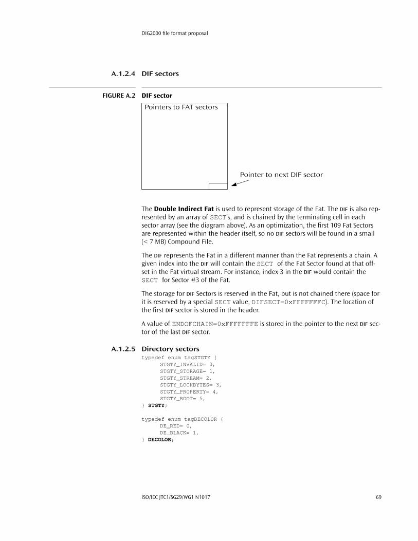
DIG2000 file format proposal
A.1.2.4 DIF sectors
FIGURE A.2 DIF sector
The Double Indirect Fat is used to represent storage of the Fat. The DIF is also rep-resented by an array of SECT’s, and is chained by the terminating cell in each sector array (see the diagram above). As an optimization, the first 109 Fat Sectors are represented within the header itself, so no DIF sectors will be found in a small (< 7 MB) Compound File.
The DIF represents the Fat in a different manner than the Fat represents a chain. A given index into the DIF will contain the SECT of the Fat Sector found at that off-set in the Fat virtual stream. For instance, index 3 in the DIF would contain the SECT for Sector #3 of the Fat.
The storage for DIF Sectors is reserved in the Fat, but is not chained there (space for it is reserved by a special SECT value, DIFSECT=0xFFFFFFFC). The location of the first DIF sector is stored in the header.
A value of ENDOFCHAIN=0xFFFFFFFE is stored in the pointer to the next DIF sec-tor of the last DIF sector.
A.1.2.5 Directory sectorstypedef enum tagSTGTY {
STGTY_INVALID= 0,STGTY_STORAGE= 1,STGTY_STREAM= 2,STGTY_LOCKBYTES= 3,STGTY_PROPERTY= 4,STGTY_ROOT= 5,
} STGTY;
typedef enum tagDECOLOR {DE_RED= 0,DE_BLACK= 1,
} DECOLOR;
Pointers to FAT sectors
Pointer to next DIF sector
ISO/IEC JTC1/SG29/WG1 N1017 69
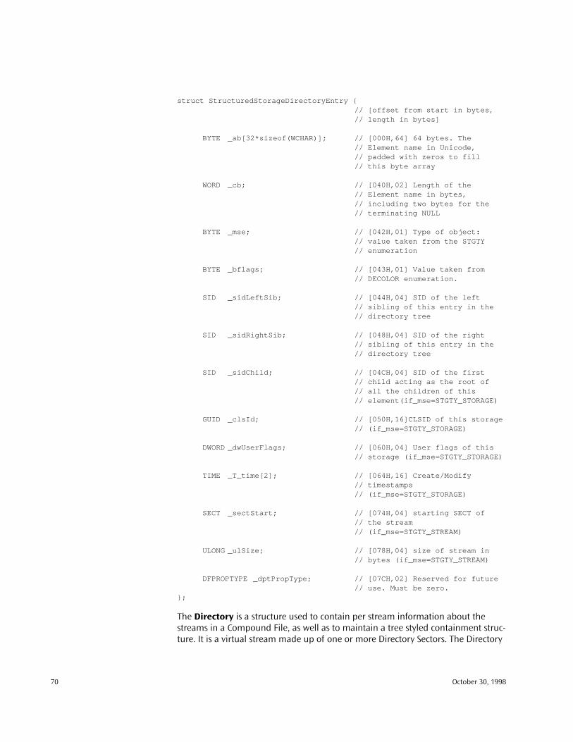
struct StructuredStorageDirectoryEntry {// [offset from start in bytes,// length in bytes]
BYTE _ab[32*sizeof(WCHAR)]; // [000H,64] 64 bytes. The // Element name in Unicode,// padded with zeros to fill// this byte array
WORD _cb; // [040H,02] Length of the// Element name in bytes,// including two bytes for the// terminating NULL
BYTE _mse; // [042H,01] Type of object:// value taken from the STGTY// enumeration
BYTE _bflags; // [043H,01] Value taken from// DECOLOR enumeration.
SID _sidLeftSib; // [044H,04] SID of the left // sibling of this entry in the// directory tree
SID _sidRightSib; // [048H,04] SID of the right // sibling of this entry in the// directory tree
SID _sidChild; // [04CH,04] SID of the first// child acting as the root of// all the children of this// element(if_mse=STGTY_STORAGE)
GUID _clsId; // [050H,16]CLSID of this storage// (if_mse=STGTY_STORAGE)
DWORD _dwUserFlags; // [060H,04] User flags of this// storage (if_mse=STGTY_STORAGE)
TIME _T_time[2]; // [064H,16] Create/Modify// timestamps // (if_mse=STGTY_STORAGE)
SECT _sectStart; // [074H,04] starting SECT of// the stream// (if_mse=STGTY_STREAM)
ULONG _ulSize; // [078H,04] size of stream in // bytes (if_mse=STGTY_STREAM)
DFPROPTYPE _dptPropType; // [07CH,02] Reserved for future// use. Must be zero.
};
The Directory is a structure used to contain per stream information about the streams in a Compound File, as well as to maintain a tree styled containment struc-ture. It is a virtual stream made up of one or more Directory Sectors. The Directory
70 October 30, 1998

DIG2000 file format proposal
is represented as a standard chain of sectors within the Fat. The first sector of the Directory chain (the Root Directory Entry)
Each level of the containment hierarchy (i.e. each set of siblings) is represented as a red/black tree. The parent of this set of siblings will have a pointer to the top of this tree. This red/black tree must maintain the following conditions in order for it to be valid:
1. The root node must always be black. Since the root directory (see below) does not have siblings, it’s color is irrelevant and may therefore be either red or black.
2. No two consecutive nodes may both be red.
3. The left child must always be less than the right child. This relationship is defined as:
◆ A node with a shorter name is less than a node with a longer name (i.e. compare the length of the name)
◆ For nodes with the same length names, compare the two names.
The simplest implementation of the above invariants would be to mark every node as black, in which case the tree is simply a binary tree.
A Directory Sector is an array of Directory Entries, a structure represented in the diagram below. Each user stream within a Compound File is represented by a sin-gle Directory Entry. The Directory is considered as a large array of Directory Entries. It is useful to note that the Directory Entry for a stream remains at the same index in the Directory array for the life of the stream—thus, this index (called an SID) can be used to readily identify a given stream.
The directory entry is then padded out with zeros to make a total size of 128 bytes.
Directory entries are grouped into blocks of four to form Directory Sectors.
A.1.2.5.1 Root Directory EntryThe first sector of the Directory chain (also referred to as the first element of the Directory array, or SID 0) is known as the Root Directory Entry and is reserved for two purposes: First, it provides a root parent for all objects stationed at the root of the multistream. Second, its function is overloaded to store the size and starting sector for the Ministream.
The Root Directory Entry behaves as both a stream and a storage. All of the fields in the Directory Entry are valid for the root. The Root Directory Entry’s Name field typ-ically contains the string “RootEntry” in Unicode, although some versions of structured storage (particularly the preliminary reference implementation and the Macintosh version) store only the first letter of this string, “R” in the name. This string is always ignored, since the Root Directory Entry is known by its position at SID 0 rather than by its name, and its name is not otherwise used. New imple-mentations should write “RootEntry” properly in the Root Directory Entry for consistency and support manipulating files created with only the “R” name.
ISO/IEC JTC1/SG29/WG1 N1017 71

A.1.2.5.2 Other Directory EntriesNon-root directory entries are marked as either stream (STGTY_STREAM) or stor-age (STGTY_STORAGE) elements. Storage elements have a _clsid, _time[] , and _sidChild values; stream elements may not. Stream elements have valid _sectStart and _ulSize members, whereas these fields are set to zero for storage elements (except as noted above for the Root Directory Entry).
To determine the physical file location of actual stream data from a stream direc-tory entry, it is necessary to determine which Fat (normal or mini) the stream exists within. Streams whose _ulSize member is less than the _ulMiniSectorCutoff value for the file exist in the ministream, and so the _startSect is used as an index into the MiniFat (which starts at _sectMiniFatStart ) to track the chain of minisectors through the ministream (which is, as noted earlier, the standard (non-mini) stream referred to by the Root Directory Entry’s _sectStart value). Streams whose _ulSize member is greater than the _ulMiniSectorCutoff value for the file exist as standard streams—their _sectStart value is used as an index into the standard Fat which describes the chain of full sectors containing their data).
A.1.2.6 Storage sectorsStorage sectors are simply collections of arbitrary bytes. They are the building blocks of user streams, and no restrictions are imposed on their contents. Storage sectors are represented as chains in the Fat, and each storage chain (stream) will have a single Directory Entry associated with it.
A.1.3 ExamplesThis section contains a hexadecimal dump of an example structured storage file to clarify the binary file format.
A.1.3.1 Sector 0: Header_abSig = DOCF 11E0 A1B1 1AE1_clid = 0000 0000 0000 0000 0000 0000 0000 0000_uMinorVersion = 003B_uDllVersion = 3_uByteOrder = FFFE (Intel byte order)_uSectorShift = 9 (512 bytes)_uMiniSectorShift = 6 (64 bytes)_usReserved = 0000_ulReserved1 = 00000000_ulReserved2 = 00000000_csectFat = 00000001_sectDirStart = 00000001_signature = 00000000_ulMiniSectorCutoff = 00001000 (4096 bytes)_sectMiniFatStart = 00000002_csectMiniFat = 00000001_sectDifStart = FFFFFFFE (no DIF, file is < 7Mb)_csectDIF = 00000000_sectFat[] = 00000000 FFFFFFFF… (continues with FFFFFFFF)
72 October 30, 1998

DIG2000 file format proposal
000000: D0CF 11E0 A1B1 1AE1 0000 0000 0000 0000 ................000010: 0000 0000 0000 0000 3B00 0300 FEFF 0900 ................000020: 0600 0000 0000 0000 0000 0000 0100 0000 ................000030: 0100 0000 0000 0000 0010 0000 0200 0000 ................000040: 0100 0000 FEFF FFFF 0000 0000 0000 0000 ................000050: FFFF FFFF FFFF FFFF FFFF FFFF FFFF FFFF ...................0001F0: FFFF FFFF FFFF FFFF FFFF FFFF FFFF FFFF ................
A.1.3.2 SECT 0: First (only) FAT sector SECT 0: FFFFFFFD = FATSECT: marks this sector as a FAT sector.
Referred to in header by _sectFat[0]SECT 1: FFFFFFFE = ENDOFCHAIN: marks the end of the directory chain,
referred to in header by _sectDirStartSECT 2: FFFFFFFE = ENDOFCHAIN: marks the end of the mini-fat,
referred to in header by _sectMiniFatStartSECT 3: 00000004 = pointer to the next sector in the “Stream 1” data.
This sector is the first sector of “Stream 1”, it is referredto by the Directory Entry
SECT 4: ENDOFCHAIN (0xFFFFFFFE): marks the end of the “Stream 1” stream data. Further Entries are empty (FREESECT =0xFFFFFFFF)
000200: FDFF FFFF FEFF FFFF FEFF FFFF 0400 0000 ................000210: FEFF FFFF FFFF FFFF FFFF FFFF FFFF FFFF ...................0003F0: FFFF FFFF FFFF FFFF FFFF FFFF FFFF FFFF ................
A.1.3.3 SECT 1: First (only) Directory sectorSID 0: Root SID: Root Name = "R"SID 1: Element 1 SID: Name = "Storage 1"SID 2: Element 2 SID: Name = "Stream 1"SID 3: Unused
A.1.3.3.1 SID 0: Root Directory Entry_ab = "R" (this should be “Root Entry”)_cb = 0004 (4 bytes, does not include double-null
terminator)_mse = 05 (STGTY_ROOT)_bflags = 00 (DE_RED)_sidLeftSib = FFFFFFFF (none)_sidRightSib = FFFFFFFF (none)_sidChild = 00000001 (SID 1: “Storage 1”)_clsid = 0067 6156 54C1 CE11 8553 00AA 00A1 F95B_dwUserFlags = 00000000 (n/a for STGTY_ROOT)_time[0] = CreateTime = 0000 0000 0000 0000 (none set)_time[1] = ModifyTime = 801E 9213 4BB4 BA01 (?)_sectStart = 00000003 (starting sector of MiniStream)_ulSize = 00000240 (length of MiniStream in bytes)_dptPropTyp e = 0000 (n/a)
000400: 0052 0000 0000 0000 0000 0000 0000 0000 .R..............000410: 0000 0000 0000 0000 0000 0000 0000 0000 ................000420: 0000 0000 0000 0000 0000 0000 0000 0000 ................000430: 0000 0000 0000 0000 0000 0000 0000 0000 ................000440: 0400 0500 FFFF FFFF FFFF FFFF 0100 0000 ................000450: 0067 6156 54C1 CE11 8553 00AA 00A1 F95B .gaVT....S.....[000460: 0000 0000 0000 0000 0000 0000 801E 9213 ................000470: 4BB4 BA01 0300 0000 4002 0000 0000 0000 K.......@.......
ISO/IEC JTC1/SG29/WG1 N1017 73
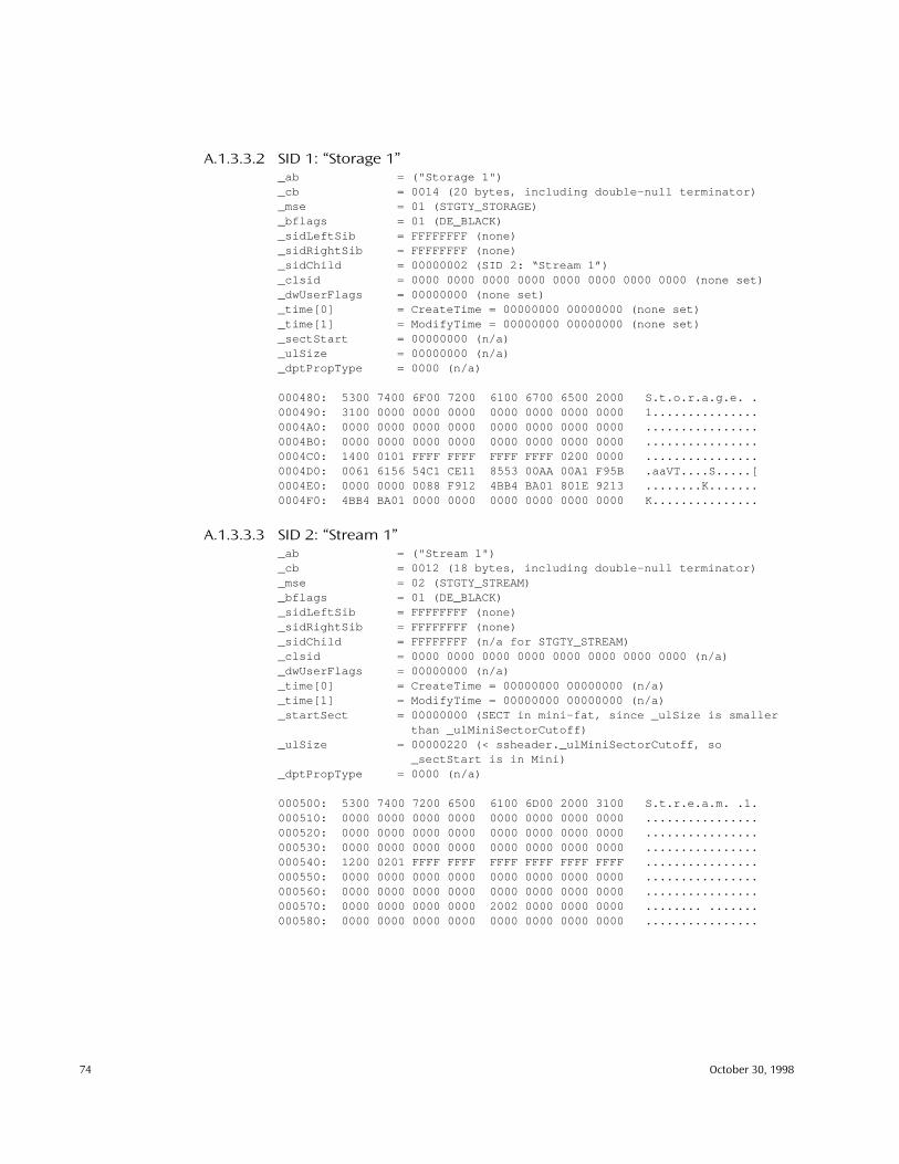
A.1.3.3.2 SID 1: “Storage 1”_ab = ("Storage 1")_cb = 0014 (20 bytes, including double-null terminator)_mse = 01 (STGTY_STORAGE)_bflags = 01 (DE_BLACK)_sidLeftSib = FFFFFFFF (none)_sidRightSib = FFFFFFFF (none)_sidChild = 00000002 (SID 2: “Stream 1”)_clsid = 0000 0000 0000 0000 0000 0000 0000 0000 (none set)_dwUserFlags = 00000000 (none set)_time[0] = CreateTime = 00000000 00000000 (none set)_time[1] = ModifyTime = 00000000 00000000 (none set)_sectStart = 00000000 (n/a)_ulSize = 00000000 (n/a)_dptPropType = 0000 (n/a)
000480: 5300 7400 6F00 7200 6100 6700 6500 2000 S.t.o.r.a.g.e. .000490: 3100 0000 0000 0000 0000 0000 0000 0000 1...............0004A0: 0000 0000 0000 0000 0000 0000 0000 0000 ................0004B0: 0000 0000 0000 0000 0000 0000 0000 0000 ................0004C0: 1400 0101 FFFF FFFF FFFF FFFF 0200 0000 ................0004D0: 0061 6156 54C1 CE11 8553 00AA 00A1 F95B .aaVT....S.....[0004E0: 0000 0000 0088 F912 4BB4 BA01 801E 9213 ........K.......0004F0: 4BB4 BA01 0000 0000 0000 0000 0000 0000 K...............
A.1.3.3.3 SID 2: “Stream 1”_ab = ("Stream 1")_cb = 0012 (18 bytes, including double-null terminator)_mse = 02 (STGTY_STREAM)_bflags = 01 (DE_BLACK)_sidLeftSib = FFFFFFFF (none)_sidRightSib = FFFFFFFF (none)_sidChild = FFFFFFFF (n/a for STGTY_STREAM)_clsid = 0000 0000 0000 0000 0000 0000 0000 0000 (n/a)_dwUserFlags = 00000000 (n/a)_time[0] = CreateTime = 00000000 00000000 (n/a)_time[1] = ModifyTime = 00000000 00000000 (n/a)_startSect = 00000000 (SECT in mini-fat, since _ulSize is smaller
than _ulMiniSectorCutoff)_ulSize = 00000220 (< ssheader._ulMiniSectorCutoff, so
_sectStart is in Mini)_dptPropType = 0000 (n/a)
000500: 5300 7400 7200 6500 6100 6D00 2000 3100 S.t.r.e.a.m. .1.000510: 0000 0000 0000 0000 0000 0000 0000 0000 ................000520: 0000 0000 0000 0000 0000 0000 0000 0000 ................000530: 0000 0000 0000 0000 0000 0000 0000 0000 ................000540: 1200 0201 FFFF FFFF FFFF FFFF FFFF FFFF ................000550: 0000 0000 0000 0000 0000 0000 0000 0000 ................000560: 0000 0000 0000 0000 0000 0000 0000 0000 ................000570: 0000 0000 0000 0000 2002 0000 0000 0000 ........ .......000580: 0000 0000 0000 0000 0000 0000 0000 0000 ................
74 October 30, 1998
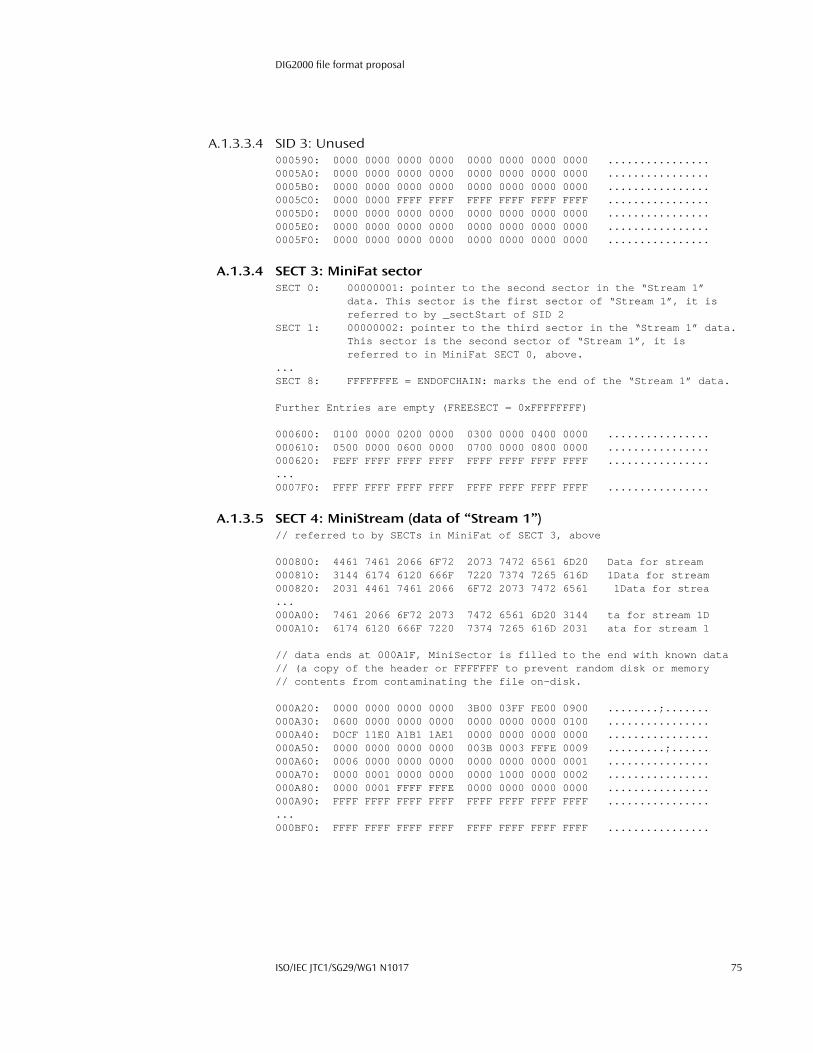
DIG2000 file format proposal
A.1.3.3.4 SID 3: Unused000590: 0000 0000 0000 0000 0000 0000 0000 0000 ................0005A0: 0000 0000 0000 0000 0000 0000 0000 0000 ................0005B0: 0000 0000 0000 0000 0000 0000 0000 0000 ................0005C0: 0000 0000 FFFF FFFF FFFF FFFF FFFF FFFF ................0005D0: 0000 0000 0000 0000 0000 0000 0000 0000 ................0005E0: 0000 0000 0000 0000 0000 0000 0000 0000 ................0005F0: 0000 0000 0000 0000 0000 0000 0000 0000 ................
A.1.3.4 SECT 3: MiniFat sectorSECT 0: 00000001: pointer to the second sector in the “Stream 1”
data. This sector is the first sector of “Stream 1”, it isreferred to by _sectStart of SID 2
SECT 1: 00000002: pointer to the third sector in the “Stream 1” data.This sector is the second sector of “Stream 1”, it isreferred to in MiniFat SECT 0, above.
...SECT 8: FFFFFFFE = ENDOFCHAIN: marks the end of the “Stream 1” data.
Further Entries are empty (FREESECT = 0xFFFFFFFF)
000600: 0100 0000 0200 0000 0300 0000 0400 0000 ................000610: 0500 0000 0600 0000 0700 0000 0800 0000 ................000620: FEFF FFFF FFFF FFFF FFFF FFFF FFFF FFFF ...................0007F0: FFFF FFFF FFFF FFFF FFFF FFFF FFFF FFFF ................
A.1.3.5 SECT 4: MiniStream (data of “Stream 1”)// referred to by SECTs in MiniFat of SECT 3, above
000800: 4461 7461 2066 6F72 2073 7472 6561 6D20 Data for stream 000810: 3144 6174 6120 666F 7220 7374 7265 616D 1Data for stream000820: 2031 4461 7461 2066 6F72 2073 7472 6561 1Data for strea...000A00: 7461 2066 6F72 2073 7472 6561 6D20 3144 ta for stream 1D000A10: 6174 6120 666F 7220 7374 7265 616D 2031 ata for stream 1
// data ends at 000A1F, MiniSector is filled to the end with known data // (a copy of the header or FFFFFFF to prevent random disk or memory // contents from contaminating the file on-disk.
000A20: 0000 0000 0000 0000 3B00 03FF FE00 0900 ........;.......000A30: 0600 0000 0000 0000 0000 0000 0000 0100 ................000A40: D0CF 11E0 A1B1 1AE1 0000 0000 0000 0000 ................000A50: 0000 0000 0000 0000 003B 0003 FFFE 0009 .........;......000A60: 0006 0000 0000 0000 0000 0000 0000 0001 ................000A70: 0000 0001 0000 0000 0000 1000 0000 0002 ................000A80: 0000 0001 FFFF FFFE 0000 0000 0000 0000 ................000A90: FFFF FFFF FFFF FFFF FFFF FFFF FFFF FFFF ...................000BF0: FFFF FFFF FFFF FFFF FFFF FFFF FFFF FFFF ................
ISO/IEC JTC1/SG29/WG1 N1017 75

A.2 OLE Property Set binary format
A.2.1 Document properties in storageIn an IStorage , a serialized property set is stored in either a single stream or in a nested IStorage instance. In the latter case, the contained stream named “Con-tents” is the primary stream containing property values. The format of the primary stream, the same in either case, is described in the next section below. None of the property types VT_STREAM, VT_STORAGE, VT_STREAMED_OBJECT, or VT_STORED_OBJECT may be used in a stream based property set; these types may only be used in storage based sets. It is the person who invents/defines a new property set who gets to choose whether the set is always stream based, is always storage based, or at times can be either.
Names in an IStorage that begin with the value ‘\0x05 ’ are reserved exclu-sively for the storage of property sets. Streams or storages that begin with ‘\0x05 ’ must therefore be in the format described below; storages so named must contain a “Contents ” stream in the format.
1 One of the things that a person who invents
a new standard property set does is specify the standard string name under which instances of that type are stored. For example, the summary information property set defined by OLE2 is always found under the name “\005SummaryInformation ". OLE2 provided no conventions for choosing this name; however, a convention for choosing such names is now strongly recom-mended below.
1. Properties may of course be stored in streams or storages that do not begin with ‘\0x05 ,’ but such properties are completely private to the application manipulating the storage; there is little reason to do this.
76 October 30, 1998

DIG2000 file format proposal
FIGURE A.3 Steam containing a serialized property set
A.2.2 Format of the primary property set streamThe overall structure of a stream containing a serialized property set is as illus-trated in Figure A.3. The format consists of a property set header, a sequence of size exactly one of format ID/offset pair, and a corresponding sequence of sections con-taining the actual property values.
1
Absolutely all the fields of a serialized property set specified here are always stored in storage in little endian (Intel) byte order.
2
The overall length of this property set stream is limited to 256k bytes.
1. The original OLE2 format allowed for more than one section, but use of that functionality is dis-couraged and no longer supported.
2. Notwithstanding the fact that there is a byte-order tag of 0xFFFE at the start of the format. This tag was intended to allow for future extensibility that has been subsequently determined to be very unlikely to be done.
Property Set Header
FMTID/Offset pair
SectionSection Header
Property ID/Offset pairs
Primary stream of a serialized property set
Byte Order Indicator(WORD)
Format Version(WORD)
Originating OS Version(DWORD)
Class Identifier(CLSID)
Reserved(DWORD)
FMTID (16 bytes) Offset* (DWORD)
Property ID for property m (DWORD)
Size of section (DWORD) Count of properties, m (DWORD)
Offset** (DWORD)Property ID for property 1 (DWORD)Property ID for property 2 (DWORD) Offset** (DWORD)
Offset** (DWORD)m entries
Type indicator m (DWORD)
Property value 1 (variable length)Type indicator 1 (DWORD)Type indicator 2 (DWORD) Property value 2 (variable length)
Property value m (variable length)m entries
Properties (Type/Value pairs)
*Offset in bytes from the start of the stream to the start of the section**Offset in bytes from the start of the section to the start of the type/value pair
ISO/IEC JTC1/SG29/WG1 N1017 77

A.2.2.1 Property Set headerAt the beginning of the property set stream is a header. The following structure illustrates the header:
typedef struct PROPERTYSETHEADER {WORD wByteOrder; // Always 0xFFFEWORD wFormat; // Should be 0DWORD dwOSVer; // System versionCLSID clsid; // Application CLSIDDWORD reserved; // Should be 1
} PROPERTYSETHEADER;
The definition of the members of this structure as follows:
wByteOrder. The byte-order indicator is a WORD and should always hold the value 0xFFFE. This is the same as the Unicode© byte-order indicator. When writ-ten in little endian (Intel) byte order, as is always done, this appears in the stream as 0xFE, 0xFF .
wFormat. The format version is a WORD and indicates the format version of this stream. Property set writers should write zero for this value. Property set readers should check this value; if it is non-zero, then they should refuse to read the set, for it is in a format that they don’t in fact understand.
dwOSVer. The OS version number is encoded as OS kind in the high order word (0 for Windows on OS, 1 for Macintosh, 2 for Windows 32-bit, 3 for UNIX) and the OS supplied version number in the low order word. For Windows on DOS and Windows 32-bit, the latter is the low order word of the result of GetVersion() .
clsid. The class identifier is the CLSID of a class that can display and/or provide programmatic access to the property values. If there is no such class, it is recom-mended that the format ID be used (see below), though a value of all zeros is also acceptable; the former simply allows for greater future extensibility.
reserved. Reserved for future use. A writer of a property set should write the value one here; a reader of a property set should only however check that the value is at least one.
A.2.2.2 Format ID/Offset pairsThis part of the serialized property set indicates two things: the FMTID that scopes the property values contained in the set, and the location within the stream at which those values are stored.
typedef struct FORMATIDOFFSET {FMTID fmtid; // semantic name of a sectionDWORD dwOffset; // offset from start of whole property set
// stream to the section} FORMATIDOFFSET;
78 October 30, 1998

DIG2000 file format proposal
The offset is the distance of bytes from the start of the whole stream to where the section begins. The format ID (FMTID) is the semantic name of its corresponding section, telling how to interpret the property values therein.
A.2.2.3 SectionsEach section is made of up a property section header followed by an array that locates each property value within the section. It is specifically not the case that the properties in this array are sorted in any particular order Offsets within this array are the distance from the start of the section to the start of the property (type, value) pair. This allows entire sections to be copied as an array of bytes without any translation of internal structure.
typedef struct PROPERTYSECTIONHEADER {DWORD cbSection; // size of section in bytes,
// which is inclusive of the byte// count itself
DWORD cProperties; // count of properties in sectionPROPERTYIDOFFSET rgprop[]; // array of property locations
} PROPERTYSECTIONHEADER;
typedef struct PROPERTYIDOFFSET {DWORD propid; // name of a propertyDWORD dwOffset; // offset from the start of the
// section to that property} PROPERTYIDOFFSET;
Each property value contains a type tag followed by the bytes of the actual prop-erty value (at last!). All type/value pairs begin on a 32-bit boundary. Thus values may be followed with null bytes to align the subsequent pair on a 32-bit boundary (note though that there is no guarantee that property values are in fact as tightly packed in a section as this restriction permits; that is, there may be additional gra-tuitous padding).
typedef struct SERIALIZEDPROPERTYVALUE {DWORD dwType; // type tagBYTE rgb[]; // the actual property value
} SERIALIZEDPROPERTYVALUE;
A consequence of these rules is that the smallest legal section, one containing zero properties, contains the following eight bytes: 08 00 00 00 00 00 00 00 .
A.2.3 Special property idsA couple of property ID’s have special significance in all property sets.
A.2.3.1 Property ID zero: Dictionary of property namesTo enable users of property sets to attach meaning to properties beyond those pro-vided by the type indicator, property ID zero (0) is reserved in all property sets for an optional dictionary giving human readable names for the properties in the set and for the property set itself. The value will be an array of (property ID, string) pairs.
The value of property ID zero is an array of property ID/string pairs. Entries in the array are the ID’s and corresponding names of the properties; these are not in any
ISO/IEC JTC1/SG29/WG1 N1017 79

particular order with respect to their property ID’s. Not all of the names of the properties in the set need appear in the dictionary: the dictionary may omit entries for properties that are assumed to be universally known by clients that manipulate the property set. Typically names for the base property sets for widely accepted standards will be omitted.
Property names that begin with the binary Unicode characters 0x0001 through 0x001F are reserved for future use.
The name indicated as corresponding to property ID zero is to be interpreted as the human readable name of the property set itself; like all property names, this may or may not be present.
The dictionary is stored as a list of property ID/string pairs; the code page for the strings involved is as indicated in property ID one. This can be illustrated using the following pseudo-structure definition for a dictionary entry (it’s a pseudo-structure because the sz[] member is variable size).
typedef struct tagENTRY {DWORD propid; // Property IDDWORD cb; // Count of bytes in the string, including
// the null at the endtchar tsz[cb]; // Zero-terminated string. Code page as
// indicated by property ID one.} ENTRY;
typedef struct tagDICTIONARY {DWORD cEntries; // Count of entries in the listENTRY rgEntry[cEntries];
} DICTIONARY;
Note the following:
◆ Property ID zero does not have a type indicator. The DWORD that indicates the count of entries sits in the usual type indicator position.
◆ The count of bytes in the string (cb ) includes the zero character that terminates the string.
◆ If the code page indicator is not 1200 (Unicode), there is no padding between entries to achieve reasonable alignment (sigh). However, if the code page indicator is Unicode, then each entry should be aligned on a DWORD boundary.
◆ If the code page indicator is not 1200 (Unicode), property names are stored DBCS strings. If the code page indicator does indicate Unicode, property name strings are stored as Unicode.
◆ Property name strings are restricted in length to 128 characters including the NULL terminating character.
A.2.3.2 Property ID one: Code Page IndicatorProperty ID one (1) is reserved as an indicator of which code page or script any not-always-Unicode strings in the property set originated from (code pages are used in Windows and scripts are from the Macintosh world). All such string values in the entire property set, such as VT_LPSTR’s, VT_BSTR’s, and the names in the prop-
80 October 30, 1998

DIG2000 file format proposal
erty name dictionary found in code page zero use characters from this one code page. If the code page indicator is not present, the prevailing code page on the reader’s machine must be assumed. If an application cannot understand the indi-cated code page, it should not try to modify strings stored in the property set.
When an application that is not the author of a property set changes a property of type string in the set, it should examine the code page indicator and take one of the following courses of action:
1. Write the new value using the code page found in the code page indicator.
2. Rewrite all string values in the property set using the new code page (including the new value), and modify the code page indicator to reflect the new code page.
Possible values for the code page indicator are given in the Win32 API reference (see the NLSAPI functions, and specifically the GetACP function) and Inside Macintosh Volume VI, §14–111. For example, the code page US ANSI is represented by 0x04e4 (or 1252 in decimal); the code page for Unicode is 1200 . Whether a Windows code page or a Macintosh script is found in property ID one is determined by the “origi-nating OS version” (PROPERTYSETHEADER::dwOSVer) of the property set as a whole. Note that there exist Windows code page equivalents for the Macintosh scripts numbers (Windows code page 10000, for example, is the Macintosh Roman script).
By far, if it is at all possible, it is recommended that the Unicode code page (1200) be used. This is the only practical way to in fact achieve worldwide interoperable property sets. In code page 1200, note especially that the count at the start of a VT_LPSTR or VT_BSTR is to be interpreted as a byte count, not a character count. The byte count includes the two zero bytes at the end of the string.
Property ID one is of type VT_I2 , and therefore consists of a DWORD containing VT_I2 followed by a USHORT indicating the code page. For example, the type/value pair for property ID one representing the US ANSI code page is the follow-ing six bytes: 02 00 00 00 e4 04 , plus any necessary padding.
A.2.3.3 Property ID 0x80000000: Locale IndicatorProperty ID 0x80000000 (PID_LOCALE) is reserved as an indication of which locale the property set was written in. The default locale for a property set, in the event that PID_LOCALE does not exist in the property set will be the system’s default locale (LOCALE_SYSTEM_DEFAULT).
Applications can choose to support locale or just get the default behavior. Applica-tions that allow users to specify a working locale should write that locale identifier to this property. Applications that use the user’s default locale (LOCALE_USER_DEFAULT) should write the user’s default locale identifier.
Applications should be concerned with the possibility of getting information from a property set which is of a different locale than the application’s locale or the user’s or the system’s (i.e. a foreign object).
There is no provision in the OLE Property Set interfaces defined above to specifi-cally read and write PID_LOCALE; in other words this property can be treated just
ISO/IEC JTC1/SG29/WG1 N1017 81

like any property. Likewise the system will not attempt to automatically add or modify this property.
Property ID PID_LOCALE is of type VT_U4, and therefore consists of a DWORD con-taining VT_U4 followed by a DWORD containing the Locale Identifier (LCID ) as defined by Appendix C of the Win32 SDK.
A.2.3.4 Reserved property ID’sProperty ID’s with the high bit set (that is, which are negative) are reserved for future definition by Microsoft.
A.2.4 Property type representationsA property (type, value) pair is a DWORD type indicator, followed by a value whose representation depends on the type. The serialized representations of each of the different types of values are as follows:
TABLE 6.4 Common property types
Type indicator Value representation
VT_EMPTY no bytes
VT_NULL no bytes
VT_I2 2 byte signed integer
VT_I4 4 byte signed integer
VT_R4 32bit IEEE floating point value
VT_R8 64bit IEEE floating point value
VT_CY 8 byte two’s complement integer (scaled by 10,000)
VT_DATE A 64bit floating point number representing the num-ber of days (not seconds) since December 31, 1899 (thus, January 1, 1900 is 2.0, January 2, 1900 is 3.0, and so on). This is stored in the same representation as VT_R8.
VT_BSTR Counted, null terminated binary string; represented as a DWORD byte count of the number of bytes in the string (including the terminating null) followed by the bytes of the string. Character set is as indicated by the code page indicator.
VT_ERROR A DWORD containing a status code.
VT_BOOL Boolean value, a WORD containing 0 (false) or –1 (true).
VT_VARIANT A type indicator (a DWORD) followed by the correspond-ing value. VT_VARIANT is only used in conjunction with VT_VECTOR: see below.
VT_UI1 1 byte unsigned integer
VT_UI2 2 byte unsigned integer
82 October 30, 1998
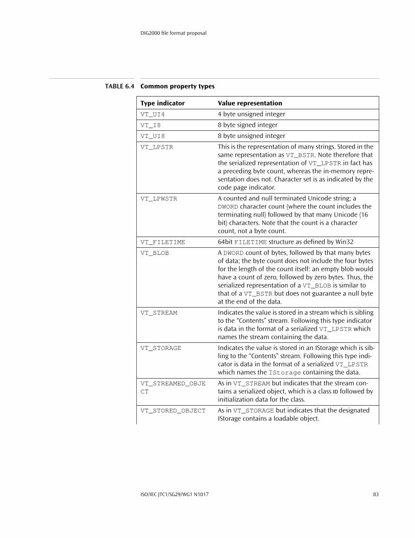
DIG2000 file format proposal
VT_UI4 4 byte unsigned integer
VT_I8 8 byte signed integer
VT_UI8 8 byte unsigned integer
VT_LPSTR This is the representation of many strings. Stored in the same representation as VT_BSTR. Note therefore that the serialized representation of VT_LPSTR in fact has a preceding byte count, whereas the in-memory repre-sentation does not. Character set is as indicated by the code page indicator.
VT_LPWSTR A counted and null terminated Unicode string; a DWORD character count (where the count includes the terminating null) followed by that many Unicode (16 bit) characters. Note that the count is a character count, not a byte count.
VT_FILETIME 64bit FILETIME structure as defined by Win32
VT_BLOB A DWORD count of bytes, followed by that many bytes of data; the byte count does not include the four bytes for the length of the count itself: an empty blob would have a count of zero, followed by zero bytes. Thus, the serialized representation of a VT_BLOB is similar to that of a VT_BSTR but does not guarantee a null byte at the end of the data.
VT_STREAM Indicates the value is stored in a stream which is sibling to the “Contents” stream. Following this type indicator is data in the format of a serialized VT_LPSTR which names the stream containing the data.
VT_STORAGE Indicates the value is stored in an IStorage which is sib-ling to the “Contents” stream. Following this type indi-cator is data in the format of a serialized VT_LPSTR which names the IStorage containing the data.
VT_STREAMED_OBJECT
As in VT_STREAM but indicates that the stream con-tains a serialized object, which is a class ID followed by initialization data for the class.
VT_STORED_OBJECT As in VT_STORAGE but indicates that the designated IStorage contains a loadable object.
TABLE 6.4 Common property types
Type indicator Value representation
ISO/IEC JTC1/SG29/WG1 N1017 83

Clipboard format identifiers, stored with the tag VT_CF, use one of five different representations:
typedef struct VTCFREP {LONG lTag;BYTE rgb[];
} VTCFREP;
VT_BLOB_OBJECT A BLOB containing a serialized object in the same rep-resentation as would appear in a VT_STREAMED_OBJECT. That is, following the VT_BLOB_OBJECT tag is a DWORD byte count of the remaining data (where the byte count does not include the size of itself) which is in the format of a class id fol-lowed by initialization data for that class.
The only significant difference between VT_BLOB_OBJECT and VT_STREAMED_OBJECT is that the former does not have the system-level storage overhead that the latter would have, and is therefore more suitable for scenarios involving numbers of small objects.
VT_CF A BLOB containing a clipboard format identifier fol-lowed by the data in that format. That is, following the VT_CF tag is data in the format of a VT_BLOB: a DWORD count of bytes, followed by that many bytes of data in the format of a packed VTCFREP described just below, followed immediately by an array of bytes as appropriate for data in the clipboard format format (text, metafile, or whatever).
VT_CLSID A class ID (or other GUID).
VT_VECTOR If the type indicator is one of the above values with this bit on in addition, then the value is a DWORD count of elements, followed by that many repetitions of the value.
As an example, a type indicator of VT_LPSTR | VT_VECTOR has a DWORD element count, a DWORD byte count, the first string data, a DWORD byte count, the second string data, and so on.
TABLE 6.4 Common property types
Type indicator Value representation
84 October 30, 1998

DIG2000 file format proposal
The values for rgb are determined by the different values for lTag :
As was mentioned above, all type/value pairs begin on a 32-bit boundary. It fol-lows that in turn, the type indicators and values of a type value pair are so aligned. This means that values may be necessarily followed by null bytes to align a subse-quent type/value pair.
However, within a vector of values, each repetition of a value is to be aligned with its natural alignment rather than with 32-bit alignment. In practice, this is only sig-nificant for types VT_I2 and VT_BOOL (which have 2-byte natural alignment); all other types have 4-byte natural alignment. Therefore, a value with type tag VT_I2 | VT_VECTOR would be:
◆ a DWORD element count, followed by◆ an sequence of packed 2-byte integers with no padding between them,
whereas a value of with type tag VT_LPSTR | VT_VECTOR would be a DWORD element count, followed by
◆ a sequence of (DWORD cch, char rgch[] ) strings, each of which may be followed by null padding to round to a 32-bit boundary.
A.3 CompObj stream binary format
A.3.1 OverviewThe ‘CompObj’ stream in a storage object provides generic information regarding the native data contained in this storage object. This generic information is manip-ulated through the OLE API functions WriteFmtUserTypeStg and ReadFmtUserTypeStg and includes:
◆ User Type: a user readable string that indicates the type of the object.
◆ Clipboard Format: implies the names and structure of streams and sub-storages.
TABLE 6.5 Relationship between lTag and rgb
lTag Value rgb value
-1L a DWORD containing a built-in Windows clipboard format value.
-2L a DWORD containing a Macintosh clipboard format value.
-3L a GUID containing a format identifier (this is in little usage).
any positive value
a null-terminated string containing a Windows clipboard format name, one suitable for passing to RegisterClipboardFor-mat . The code page used for characters in the string is per the code page indicator. The “positive value” here is the length of the string, including the null byte at the end.
0L no data (very rare usage)
ISO/IEC JTC1/SG29/WG1 N1017 85

This document exposes the binary format of the data written by WriteFmtUser-TypeStg and interpreted by ReadFmtUserTypeStg .
A.3.2 FormatThe format consists of three basic parts, that represent versions of the stream writ-ten by different versions of the OLE2 libraries:
◆ Header, User Type (ANSI), Clipboard format (ANSI)
◆ ProgID (ANSI): optional. If not present, no Unicode information may follow
◆ Unicode versions of User Type, Clipboard format and ProgID: optional. If any Unicode information is present all three items have to be valid. Presence of the Unicode information is indicated by a “magic DWORD” value following the ANSI ProgID.
The following is a detailed description of the format using a pseudo C++ syntax where applicable.
A.3.2.1 Mandatory part
A.3.2.1.1 Stream name // Stream name: L”\1CompObj”
A.3.2.1.2 Headerstruct CompObjHdr { // The leading data in the
// CompObj streamDWORD dwVersionAndByteOrder;
// First DWORD: LOWORD Version=0x0001,// HIWORD=FFFE (ignored by reader!)
DWORD dwFormat = 0x00000a03;// OS Version: always Win 3.1
DWORD unused = -1L; // Always a -1L in the stream
CLSID clsidClass; // Class ID of this object, identical// to the CLSID in the parent storage// of the stream
};
A.3.2.1.3 User Typestruct ANSIUserType {
DWORD dwLenBytes; // length of User Type string in bytes// including terminating 0
char szUserType[dwLenBytes];// User Type string (ANSI) terminated// with '\0'
}
86 October 30, 1998
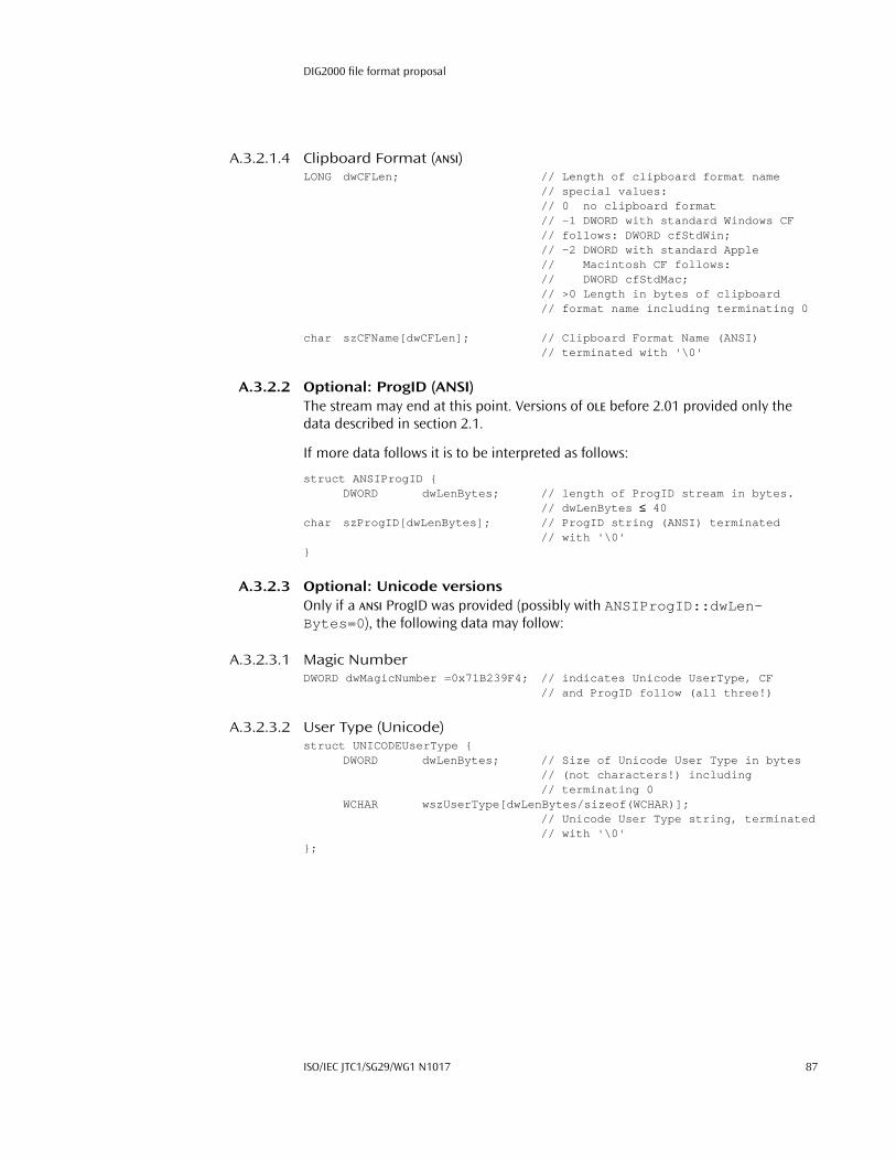
DIG2000 file format proposal
A.3.2.1.4 Clipboard Format (ANSI)LONG dwCFLen; // Length of clipboard format name
// special values:// 0 no clipboard format// -1 DWORD with standard Windows CF// follows: DWORD cfStdWin;// -2 DWORD with standard Apple// Macintosh CF follows:// DWORD cfStdMac;// >0 Length in bytes of clipboard// format name including terminating 0
char szCFName[dwCFLen]; // Clipboard Format Name (ANSI)// terminated with '\0'
A.3.2.2 Optional: ProgID (ANSI)The stream may end at this point. Versions of OLE before 2.01 provided only the data described in section 2.1.
If more data follows it is to be interpreted as follows:
struct ANSIProgID {DWORD dwLenBytes; // length of ProgID stream in bytes.
// dwLenBytes ≤ 40char szProgID[dwLenBytes]; // ProgID string (ANSI) terminated
// with '\0'}
A.3.2.3 Optional: Unicode versionsOnly if a ANSI ProgID was provided (possibly with ANSIProgID::dwLen-Bytes=0 ), the following data may follow:
A.3.2.3.1 Magic NumberDWORD dwMagicNumber =0x71B239F4; // indicates Unicode UserType, CF
// and ProgID follow (all three!)
A.3.2.3.2 User Type (Unicode)struct UNICODEUserType {
DWORD dwLenBytes; // Size of Unicode User Type in bytes// (not characters!) including// terminating 0
WCHAR wszUserType[dwLenBytes/sizeof(WCHAR)];// Unicode User Type string, terminated// with '\0'
};
ISO/IEC JTC1/SG29/WG1 N1017 87
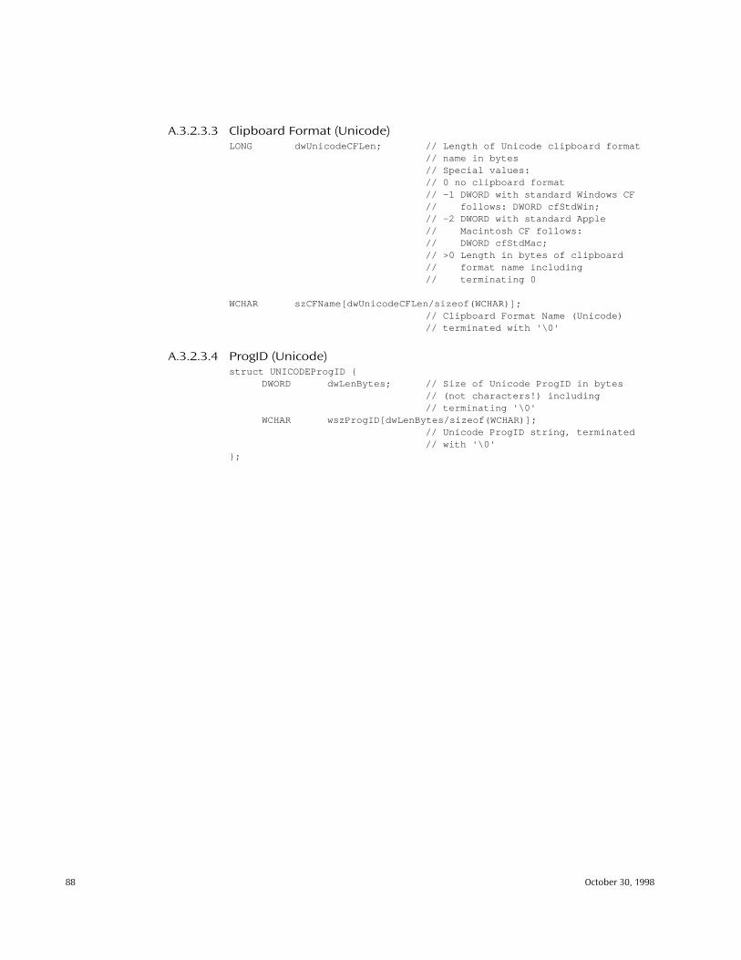
A.3.2.3.3 Clipboard Format (Unicode)LONG dwUnicodeCFLen; // Length of Unicode clipboard format
// name in bytes// Special values:// 0 no clipboard format// -1 DWORD with standard Windows CF// follows: DWORD cfStdWin;// -2 DWORD with standard Apple// Macintosh CF follows:// DWORD cfStdMac;// >0 Length in bytes of clipboard// format name including// terminating 0
WCHAR szCFName[dwUnicodeCFLen/sizeof(WCHAR)];// Clipboard Format Name (Unicode)// terminated with '\0'
A.3.2.3.4 ProgID (Unicode)struct UNICODEProgID {
DWORD dwLenBytes; // Size of Unicode ProgID in bytes// (not characters!) including// terminating '\0'
WCHAR wszProgID[dwLenBytes/sizeof(WCHAR)];// Unicode ProgID string, terminated// with '\0'
};
88 October 30, 1998

B: Example API
The following text is an excerpt from the Netgraphica™ Image Source Reference Guide [15], part of the developers documentation from TrueSpectra’s Flashpix tool-kit. This excerpt is not edited such that it stands alone, and there may be references to portions of the full document that are not included here. If you have further questions about this information, contact Steve Sutherland at [email protected].
This documentation shows an example of an API that could be used to efficiently access image data from a DIG2000 file in a resolution-independent and block/tile oriented mode.
B.1 Using the ImageSource interface
This section describes how to use the ImageSource Interface in a Client Applica-tion. The following sections are included:
◆ Introduction◆ Image representation◆ Loading an image◆ Getting tiles
B.1.1 IntroductionThe ImageSource interface can be used for manipulating image data which has multiple resolutions, and can be accessed by tiles (small square blocks of image data) rather than by scanline. These are two essential features of the .fpx-format image and the corresponding Internet Imaging Protocol (IIP). They make accessing image data more efficient because an application has the ability to request only the region of the image it needs at the resolution it needs.
ImageSource and other related interfaces provide methods to access to all the possible information in an .fpx-format or IIP image, but only a small subset of these methods is needed in a typical client application for displaying the image data.
This document describes how to use the ImageSource package in the context of a client application. We will begin by giving a brief overview of how the image data is represented, and then go on to show how to access the image data through the ImageSource interface with examples.
For more detailed information about the interfaces and classes used here, refer to Appendix B.2.
ISO/IEC JTC1/SG29/WG1 N1017 89

B.1.2 Image representation
B.1.2.1 Multiple resolutions Image data is available at a hierarchy of resolutions; each is one-half the size (rounded up to the nearest pixel) of the next higher one. Resolution levels are assigned from lowest to highest. The lowest resolution image is always at level 0, and if there are n levels in the hierarchy the highest resolution image is at level n–1.
B.1.2.2 Tiles Each resolution is broken up into square 64×64 pixel tiles. Tiles are indexed in row major order from left-to-right and from top-to-bottom. Within the tiles the pixels are also ordered from left-to-right and top-to-bottom. The tiles at the right and bot-tom edges of the image are padded by replicating the last row and column if the width or height of the resolution are not exact multiples of the tile width and height.
B.1.2.3 Example The following table shows the sizes for all the resolutions of a 500 x 300 pixel image.
B.1.3 Loading an image To load an imagesource, we first construct an ImageSource object; in this case it is an IIPImageSource . The image is loaded using the load() method which returns a boolean value indicating whether the load was successful or not. In the case of the IIPImageSource , the load method does not request any pixel data from the server; it just loads the basic information about the image such as num-ber of resolutions, pixel size of the resolutions, colorspace, and information which may be needed later to decompress image data when it arrives.
In C++, we first get an instance of an IIPModule , and use the load method to obtain an instance of an ImageSource . Here is the code to do it:
// image source interface#include "ImageSource.h"...
TABLE B.1 Example resolution sizes
Res level Pixel width Pixel height Tile width Tile height
3 500 300 8 5
2 250 150 4 3
1 125 75 2 2
0 63 38 1 1
90 October 30, 1998

DIG2000 file format proposal
// load image from URL and get the size of the highest resolutionchar *url =
"http://www.truespectra.com/cgibin/NetGraphicaCGI.exe? fif=cat.fpx";ImageSourceModule *isMod = newIIPModule();ImageSource *source = isMod->load(url);if (!source) {
// do something on failure...
}
Once the image has been successfully loaded we can, for example, determine the pixel size of the highest resolution. First we query the number of resolutions, and then use that to query the pixel size of the image at the highest resolution level.
In C++ it would be:
int nRes = source->getResCount();Dimension size;source->getPixelSize(nRes-1 &size);
B.1.4 Getting tiles Tiles can be requested by specifying a resolution level and a rectangle. The rectan-gle is specified in the pixel coordinates of the selected resolution. First we get a list of the indices of the tiles that are needed to cover a given rectangle, then we get the corresponding set of tiles.
In C++ the code to do this looks like:
// rectangle specifying all of resolution level 3Dimension size;source->getPixelSize(3, &size);Rect rect(0, 0, size.width, size.height);
// get list of tiles in specified rectangleTileList *needTiles = source->getRectTileList(3, &rect);
// get the set of tiles specified in the tile listTileSet *tSet = source->getTileSet(3, needTiles);
An individual tile can be retrieved from the TileSet by tile index using the get-Tile() method. The tile index can be specified directly, or an enumeration of the indices for all the tiles in the TileSet can be retrieved using the getTileL-ist() method.
In C++ the code to retrieve a tile looks like this:
ISO/IEC JTC1/SG29/WG1 N1017 91

TileList *gotTiles = tSet->getTileList();while (gotTiles->hasMoreElements()) {
// get a tileint tIndex = gotTiles->getNext();Tile *tile = tSet->getTile(tIndex);// do something with it...tile->Release();
}tSet->Release();gotTiles->Release();
B.2 C++ documentation
This section describes the interfaces and classes available in the C++ version of the Netgraphica Client Toolkit. The following contents are included:
◆ .fpx-format related interfaces◆ ImageSource related interfaces◆ Property Set related interfaces◆ Render2D base types◆ Hierarchy of C++ classes
B.2.1 .fpx-format related interfacesThese interfaces provide access to reading and writing image data in the .fpx-format.
An .fpx-format image view object is comprised of a ViewTransform specifying some transformation parameters, an ImageSource for the source image data, and optionally an ImageSource to cache the result image which is generated by applying the ViewTransform to the source image. In addition there is non-image data describing various attributes of the image such as the subject, author, scanner setting, camera settings, etc. as appropriate.
The main interfaces described below are the FpxViewProperties interface which provides access to the non-image data, the FpxFile interface which associ-ates source image data in with the transform and property interfaces, and the FpxFileModule is a collection of methods for loading and saving files in the .fpx-format.
B.2.1.1 Interfaces
ThumbNail. The Thumbnail interface is used to access the thumbnail image showing the rendered result image with all transforms applied.
FpxObjectProperties. This interface provides methods for manipulating prop-erty sets associated with .fpx-format view and image objects.
92 October 30, 1998

DIG2000 file format proposal
FpxImageProperties. This interface provides methods for manipulating the properties associated with an .fpx-format image object.
FpxViewProperties. This interface provides methods for manipulating the prop-erties associated with the root .fpx-format view object.
FpxFile. The FpxFile interface associates a ViewTransform with source image data.
FpxFileModule. A FpxFileModule provides a collection of methods for load-ing and saving data in .fpx-format files.
6.4.0.1 See AlsoImageSource , ViewTransform
B.2.2 ImageSource related InterfacesThese interfaces provide access to tiled image data at multiple resolutions. Image data is provided at a hierarchy of resolutions, and data at an individual resolution is broken into square tiles. The benefits of using these interfaces are that applica-tions can select an appropriate resolution, and request only the tiles that they need. This speeds up the loading and manipulation of the image data.
This form of image data reflects the essential elements of the .fpx image file for-mat and the Internet Imaging Protocol (IIP), however these interfaces may also be implemented for other image file formats, as well as procedural images.
B.2.2.1 Interfaces
Colorspace. The Colorspace interface provides methods to get information about the colorspace of the image data associated with it.
CompressionInfo. This interface encapsulates a collection of CompressionT-ables which contain the information needed to decompress a JPEG encoded tile data obtained from an ImageSource .
CompressionParameters. This interface allows an application to set .fpx-for-mat compression parameters.
CompressionTable. This interface allows an application to access the data in a JPEG header only stream which contains the huffman and quantization tables needed to decode tiles.
ImageBuffer. This interface provides access to basic information about an image: its dimensions in pixels, colorspace, and pixel data.
ImageSource. The ImageSource interface provides access to image data at a hierarchy of resolutions on a tile basis.
ISO/IEC JTC1/SG29/WG1 N1017 93

ImageSourceModule. An ImageSourceModule is used to load image data from an image file and provide an ImageSource interface to that data.
Matrix4D. A class representing a 4×4 matrix.
Tile. This interface allows an application to access information about a single tile of an image.
TileList. This interface allows an application to enumerate a set of tile indices from one of the resolution levels of an image.
TileSet. This interface provides access to a subset of all the tiles at a particular res-olution level.
ViewTransform. The ViewTransform interface is used to get and set the parameters for the various transformations allowed by the .fpx-format.
B.2.2.2 See AlsoImageSource , ImageSourceModule
B.2.3 Property Set related InterfacesThese classes allow an application to read and write information in property sets.
B.2.3.1 Interfaces
PropertySetException. Base class for property set exceptions.
PropertyIdNotFoundException. Exception indicating that the application tried to get the value of or delete a property that did not exist in a PropertySet .
PropertyWrongTypeException. Exception indicating that the application used a PropertyValue method for retrieving the value of a property that did not match the type of the PropertyValue .
ByteArray. A class which holds an array of bytes and a count of those bytes.
PropertyValue. This interface allows an application to retrieve property values.
PropertySet. This interface allows an application to read, modify and create properties in a property set.
PropertyValueFactory. This interface allows an application to construct Prop-ertyValue which may be used to set values for properties in property sets.
B.2.4 Render2D Base Types
Affine2D. This class represents an affine transformation of a 2D coordinate space.
94 October 30, 1998
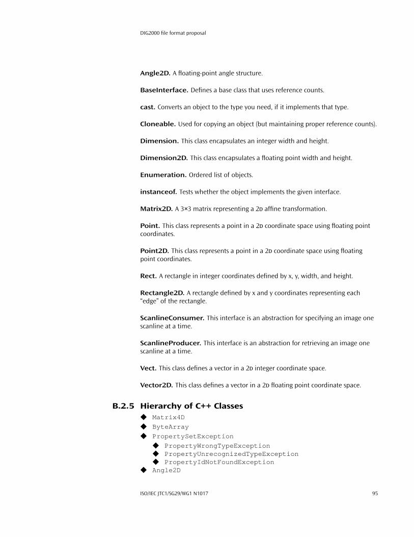
DIG2000 file format proposal
Angle2D. A floating-point angle structure.
BaseInterface. Defines a base class that uses reference counts.
cast. Converts an object to the type you need, if it implements that type.
Cloneable. Used for copying an object (but maintaining proper reference counts).
Dimension. This class encapsulates an integer width and height.
Dimension2D. This class encapsulates a floating point width and height.
Enumeration. Ordered list of objects.
instanceof. Tests whether the object implements the given interface.
Matrix2D. A 3×3 matrix representing a 2D affine transformation.
Point. This class represents a point in a 2D coordinate space using floating point coordinates.
Point2D. This class represents a point in a 2D coordinate space using floating point coordinates.
Rect. A rectangle in integer coordinates defined by x, y, width, and height.
Rectangle2D. A rectangle defined by x and y coordinates representing each “edge” of the rectangle.
ScanlineConsumer. This interface is an abstraction for specifying an image one scanline at a time.
ScanlineProducer. This interface is an abstraction for retrieving an image one scanline at a time.
Vect. This class defines a vector in a 2D integer coordinate space.
Vector2D. This class defines a vector in a 2D floating point coordinate space.
B.2.5 Hierarchy of C++ Classes◆ Matrix4D
◆ ByteArray
◆ PropertySetException
◆ PropertyWrongTypeException◆ PropertyUnrecognizedTypeException◆ PropertyIdNotFoundException
◆ Angle2D
ISO/IEC JTC1/SG29/WG1 N1017 95

◆ BaseInterface
◆ ScanlineProducer◆ ScanlineConsumer◆ Enumeration◆ Cloneable
◆ Affine2D◆ PropertyValueFactory◆ PropertyValue◆ PropertySet◆ ViewTransform◆ TileSet◆ TileList◆ ImageSourceModule◆ ImageSource◆ ImageBuffer
◆ Tile◆ CompressionTable◆ CompressionParameters◆ CompressionInfo◆ Colorspace◆ ThumbNail◆ FpxObjectProperties
◆ FpxViewProperties◆ FpxImageProperties
◆ FpxFileModule◆ FpxFile
◆ Dimension
◆ Dimension2D
◆ Matrix2D
◆ Point
◆ Point2D
◆ Rect
◆ Rectangle2D
◆ Vect
◆ Vector2D
96 October 30, 1998

C: Enhancements for Windows
Although the DIG2000 file format contains no elements that preclude its use on any particular platform, there are a few optimizations that can be made to files to allow them to interact more fluidly on the Windows platforms (Windows 95/98/NT).
C.1 Property sets
Structured storage defines property sets as a stream for storing tagged data. As defined, property sets are very flexible. All property sets must be in Windows For-mat (e.g. little endian). Windows format is indicated in the property set header by setting the wByteOrder field to 0xFFFE and the wFormat field to 0x0 . Further-more, the codepage must be written into the requisite property (property ID = 1) in each and every DIG2000 property set as described below. A binary specification of property sets is included in this specification in Section A.2.
With the sole exception of the OLE standard Summary Information Property Set (Appendix C.2), each and every DIG2000 property set must be in the Unicode (1200) codepage, and all strings in that set must be stored as wide 16-bit characters (VT_LPWSTR). Due to its origin and use in non-DIG2000 applications, the Summary Information Property set has different conditions than all other property sets. This property set must be in local code page of the system on which the file is to be loaded, and all strings in that property set must be stored as required for that code page.
The properties defined for each property set are listed in the property set defini-tion. All property ID codes not explicitly listed for the property set are reserved for future use. Where valid property values are listed, those not explicitly listed are reserved for future use.
Each property set must have a class ID, and must have one and only one section with a defined format ID. The class ID of the property set must be the same value as the format ID of the section.
Also, all properties in all property sets in a DIG2000 file must be of the type indi-cated in this specification. Any properties that allow their types to vary from file to file are explicitly noted.
ISO/IEC JTC1/SG29/WG1 N1017 97

C.2 Summary Information property set
Stream name: \005 SummaryInformationClass ID: F29F85E0-4FF9-1068-AB91-08002B27B3D9Format ID: F29F85E0-4FF9-1068-AB91-08002B27B3D9
Structured Storage defines one property set that may be found in every DIG2000
object to provide a basic level of information about the object. It is defined as part of Structured Storage and is intended to be used as a standard interchange mecha-nism for generic document information. The Summary Information property set must be written in the local code page of the system on which the file will be read. The Summary Information property set is optional in all DIG2000 files, and each property within the property set is also optional when the property set is written.
The property set must also have exactly one section that has a format ID the same as the class ID. The properties of the Summary Information property set are listed in Table 6.6. See Appendix A.2.4 for the definitions of the property types (such as VT_LPSTR).
Title. This property is available for the application to record a title for the image.
TABLE 6.6 Valid properties of the Summary Information property set
Property name ID code Type
Title 0x00000002 VT_LPSTR
Subject 0x00000003 VT_LPSTR
Author 0x00000004 VT_LPSTR
Keywords 0x00000005 VT_LPSTR
Comments 0x00000006 VT_LPSTR
Template 0x00000007 VT_LPSTR
Last saved by 0x00000008 VT_LPSTR
Revision number 0x00000009 VT_LPSTR
Total editing time 0x0000000A VT_FILETIME
Last printed 0x0000000B VT_FILETIME
Create time/date 0x0000000C VT_FILETIME
Last saved time/date 0x0000000D VT_FILETIME
Number of pages 0x0000000E VT_I4
Number of words 0x0000000F VT_I4
Number of characters 0x00000010 VT_I4
Thumbnail 0x00000011 VT_CF
Name of creating application 0x00000012 VT_LPSTR
Security 0x00000013 VT_I4
98 October 30, 1998

DIG2000 file format proposal
Subject. This property is available for the application to record the subject of the image.
Author. This property is available for the application to record the author of the image.
Keywords. This property is available for the application to record keywords about the image.
Comments. This property is available for the application to record comments about the image.
Template. This property is not used with DIG2000 files.
Last saved by. This property is available for the application to record the name of the user who last saved the image.
Revision number. This property is available for the application to record the number of times the image has been saved.
Total editing time. This property is available for the application to record the duration of an image editing session.
Last printed. This property is available for the application to record when the image was last printed.
Create date/time. This property is available for the application to record the cre-ation date and time for the image. This value should not be updated after it is initially written.
Last saved date/time. This property is available for the application to record the date and time that the image is saved. It is strongly recommended that this property be used in DIG2000 files.
Number of pages. This property is not used in DIG2000 files.
Number of words. This property is not used in DIG2000 files.
Number of characters. This property is not used in DIG2000 files.
Thumbnail. This property is available for the application to record a small bit-map representation of the image. Although the thumbnail is optional, it must be written according to the following rules if present:
◆ Thumbnail data should reflect image contents within the thumbnail format limits and must be oriented the same way as the JPEG 2000 compressed bitstream (see Section 3.4).
ISO/IEC JTC1/SG29/WG1 N1017 99

◆ The thumbnail image is stored in CF_DIB format which is a simple rectangular array of pixels with a small header as defined in [7].
◆ For single channel images (including opacity only images), treat them as monochrome without an opacity channel for purposes of the thumbnail.
◆ For multicolored images, all pixels are stored in 24 bit (bi.BitCount = 24 ) BGR format in the sRGB color space. For single channel images, all pixels are stored in either 8 bit (bi.BitCount = 8 ) format, or in 24 bit BGR format.
◆ Palletized color representations are not allowed for 24 bit DIB’s. However, for single channel thumbnails stored in 8 bit format, a palette entry must be provided which serves as the 8 to 24 bit identity lookup table. It is highly suggested that this palette be a pure greyscale ramp of exactly 256 RGBQUAD elements (e.g. biClrUsed = 0 ) running from black to white. The palette should consist of a sequence of 256 32-bit RGBQUAD structures [x,x,x,0] for all x running from 0 to 255. Note that DIB palettes require the fourth (reserved) channel to be identically zero as defined in [7].
◆ The thumbnail image data is stored uncompressed.
◆ For images with an opacity channel in addition to image data channels, the thumbnail should be stored as if it had been composited on a fully opaque white background.
◆ The larger of the thumbnail stored height and width should be approximately 96 pixels. The image should be resized to this dimension instead of padding a smaller image. It is not required to pad the smaller dimension to 96 pixels. Thumbnails that are significantly larger or smaller than this size generally cannot be used effectively.
Name of creating application property. This property is available to the application to record the name of the application that created the image. It is strongly recommended that this property be used in DIG2000 files.
Security property. This property is not used in DIG2000 files.
C.3 CompObj stream
A DIG2000 file may also have a CompObj type stream. If a CompObj stream is present, the class ID of the file is required to be stored in the Clipboard Format field of the CompObj stream as well as in the header of the storage. If a CompObj stream exists, the clipboard format field should be used to determine the class ID of the file.
The DIG2000 class ID is converted to a string for storage in the Clipboard Format field and must be enclosed within the brace characters ‘{’ and ‘}’ just as returned by the Win32™ OLE™ function StringFromGUID2() .
The CompObj stream User Type field is generally used to store the User Type infor-mation from the OLE registry for the class ID. In OLE-enabled environments, the
100 October 30, 1998

DIG2000 file format proposal
string contents should be retrieved from the OLE registry. In non-OLE enabled envi-ronments, a string, which is a user understandable brief description of the object contents, should be used.
The CompObj stream ProgID field is generally used to store the ProgID informa-tion from the OLE registry for the class ID. In OLE enabled environments, the string contents should be retrieved from the OLE registry. In non-OLE enabled environ-ments, a string which identifies the program associated with the class ID should be used. This string cannot contain any spaces.
See Appendix A.3 for a detailed definition of the CompObj stream format.
ISO/IEC JTC1/SG29/WG1 N1017 101

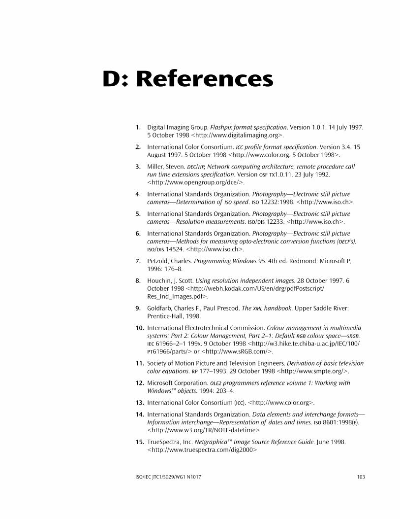
ISO/IEC JTC1/SG29/WG1 N1017 103
D: References
1. Digital Imaging Group. Flashpix format specification. Version 1.0.1. 14 July 1997. 5 October 1998 <http://www.digitalimaging.org>.
2. International Color Consortium. ICC profile format specification. Version 3.4. 15 August 1997. 5 October 1998 <http://www.color.org. 5 October 1998>.
3. Miller, Steven. DEC/HP, Network computing architecture, remote procedure call run time extensions specification. Version OSF TX1.0.11. 23 July 1992. <http://www.opengroup.org/dce/>.
4. International Standards Organization. Photography—Electronic still picture cameras—Determination of ISO speed. ISO 12232:1998. <http://www.iso.ch>.
5. International Standards Organization. Photography—Electronic still picture cameras—Resolution measurements. ISO/DIS 12233. <http://www.iso.ch>.
6. International Standards Organization. Photography—Electronic still picture cameras—Methods for measuring opto-electronic conversion functions (OECF’s). ISO/DIS 14524. <http://www.iso.ch>.
7. Petzold, Charles. Programming Windows 95. 4th ed. Redmond: Microsoft P, 1996: 176–8.
8. Houchin, J. Scott. Using resolution independent images. 28 October 1997. 6 October 1998 <http://webh.kodak.com/US/en/drg/pdfPostscript/Res_Ind_Images.pdf>.
9. Goldfarb, Charles F., Paul Prescod. The XML handbook. Upper Saddle River: Prentice-Hall, 1998.
10. International Electrotechnical Commission. Colour management in multimedia systems: Part 2: Colour Management, Part 2–1: Default RGB colour space—sRGB. IEC 61966–2–1 199x. 9 October 1998 <http://w3.hike.te.chiba-u.ac.jp/IEC/100/PT61966/parts/> or <http://www.sRGB.com/>.
11. Society of Motion Picture and Television Engineers. Derivation of basic television color equations. RP 177–1993. 29 October 1998 <http://www.smpte.org/>.
12. Microsoft Corporation. OLE2 programmers reference volume 1: Working with Windows™ objects. 1994: 203–4.
13. International Color Consortium (ICC). <http://www.color.org>.
14. International Standards Organization. Data elements and interchange formats—Information interchange—Representation of dates and times. ISO 8601:1998(E). <http://www.w3.org/TR/NOTE-datetime>
15. TrueSpectra, Inc. Netgraphica™ Image Source Reference Guide. June 1998. <http://www.truespectra.com/dig2000>