isolated foundation fd+ block foundation fdb+ · pdf filethe fd+ application allows you to...
TRANSCRIPT

Isolated Foundation FD+ Block Foundation FDB+
FRILO Software GmbH
www.frilo.com
As of 07.12.2017

FD + / FDB+
FRILO Software GmbH Page 3
Foundation FD+ / FDB+
Note: The description is limited to the Eurocode-specific application. Documents referring to former standards are available in our document archive at www.frilo.eu >>Service >> Documentation >>Manuals >>Archive.
Contents
Application options 4 Basis of calculation 5 Reinforced concrete 5 Shear resistance verification 7 Basis of calculation for verifications in foundation engineering 9 Data entry 12 Basic parameters 12 System 13
Foundation 13 Column 14 Pocket 14 Soil 16
Loads 18 Load Cases 18 Single Loads 21 Line Loads 21 Area Loads 22
Design / Verifications 23 Settings - Program settings 23 Punching 24
Sector model 25 Reinforcement 27
Enhanced reinforcement dialog 28 Column / connection 29
Pocket reinforcement 30 Area selection 31
Notes concerning the selected reinforcement 32 Soil engineering 33 Pocket (Sleeve) foundation 35 Block Foundation 40 Output 41 Explanatory notes on the output of the results (table) 42
Output of the reinforcement 42 Evaluation of the results 42 Output: Punching shear resistance verification 44

Isolated- / Block Foundation
Page 4 Software for structural calculation and design
Application options
The FD+ application allows you to verify squared and rectangular foundations cast with or without pocket. External loads can optionally apply centrically or with a uniaxial or biaxial eccentricity.
The software application calculates the soil pressure underneath the four corner points and the position of the zero-line in case of a gaping joint.
The required flexural reinforcement is calculated for the foundation and the punching shear resistance verification is performed.
You can optionally calculate the required connection reinforcement (Option "Connection Reinforcement" under Output).
The system consists of the foundation slab and an optional
column
with optional eccentricity
The flexural design is performed at the centre of the column (axis) – the graph of the moment will be rounded. Optional it is performed at the column edge.
You can include the following load types in the calculation:
- Single vertical load V at the column location
- Horizontal loads Hx und Hy. The horizontal loads are acting (see graphic below) - at the top edge of footing or - if a column was defined, at the top edge of the column and - if a pocket was defined, at the top of the pocket. horizontal loads are generating a moment (effects in the sole) - as an option the horizontal loads can act directly at the sole without generating a moment.
- Outer moments Mx and My
- Earth surcharge load and additional uniformly distributed load applying to the foundation surface without column and additional vertical single loads applying at freely selectable points.
FD + / FDB+
FRILO Software GmbH Page 5
Basis of calculation
Reinforced concrete Available standards
- DIN EN 1992-1-1:2011/2012/2013
- ÖNORM EN 1992-1-1:2011
- BS EN 1992-1-1:2009
- EN 1992:2010
- DIN EN 1997-1, ÖNORM EN 1997-1, BS EN 1997-1 still available: - DIN 1045:1988
- DIN 1045-1 (2001 + 2008)
- ÖNORM B4700:2001
- DIN 1054:1976, DIN 1054:2005
The flexural design is performed in accordance with the kh- or kd-method.
The punching shear resistance is verified in accordance with the selected reinforced concrete standard. The constructive rules specified by the Booklets 240 and 525 issued by the German Committee for Reinforced Concrete DAfStb are considered.
The decisive reduced shear force Qred is calculated by reducing the existing column load by the reaction force of the soil pressure portion attributed to the base surface of the punching cone.
The shear resistance verification is performed if the foundation geometry produces a uniaxial supporting behaviour.
For pocket foundations the following distinction is made:
- In combination with a rough/toothed pocket surface, the punching cone can be assumed outgoing from the surface of the pocket because the effect of the composite action allows such load distribution.
- In combination with a smooth pocket surface, the column base is considered to be the upper boundary of the punching cone.
- If the total bottom face of the foundation is inside the punching cone assumed with an inclination angle of 45 degrees, the verification can be dispensed with.
The column moments and horizontal forces are decomposed into the equivalent force groups Ho and Hu. An inclined strut D results. The inner lever arm z depends on the roughness of the surfaces. The limiting cases "smooth pocket surface, no bond" and "rough pocket surface, full bond" are distinguished. The lever arm z is assumed to be approximately 6/10 of the penetration depth t with no bond. With full bond, its value is multiplied with 1.4. If the bond is not ensured by appropriate measures, additional reinforcement should be installed to compensate the lower force component Hu.

Isolated- / Block Foundation
Page 6 Software for structural calculation and design
Illustration: Pocket with smooth surface
Illustration: Pocket with rough surface

FD + / FDB+
FRILO Software GmbH Page 7
Shear resistance verification If the option "Shear force as beam" is activated in the "Design" menu, the software checks whether the foundation geometry produces a uniaxial supporting behaviour and if so, verifies the shear resistance.
This can happen in the three cases described below.
Meaning of the variables:
d Statically effective height of the foundation
h Foundation height (in z-direction)
a1, a2 Distances of the column to the foundation edge on the left and right (in x-direction)
a3, a4 Distances of the column to the foundation edge at the front and rear (top and bottom in the illustration, in y-direction)
cx Column dimension in x-direction (width)
cy Column dimension in y-direction (length)
Case 1:
The distances of two opposite column or pocket sides to the foundation edges are smaller than or equal to the statically effective height d. At the same time, the distance of one of the remaining sides to the foundation edge is greater than d (see illustration 1).
Illustration 1:
a1 and a2 <= d
a3 and/or a4 > d
In this case, only shear resistance, not punching shear resistance, is verified.
If the pressure is unevenly distributed along the shear section, the shear resistance is verified in the area with high pressure (see illustration 1a).
Shear force resultant with variable pressure distribution along the shear section.
Examined area of the resulting shear force in the shear resistance verification section
top
bottom
Illustration 1a

Isolated- / Block Foundation
Page 8 Software for structural calculation and design
Case 2:
The dimensions of the pocket or column are comparable to those of a wall.
a1 > d and a2 > d and cx > a1 + a2 + cy + cy + Ls (Ls ≥ 1 m)
According to Booklet 240 of the German Committee for Reinforced Concrete DAfStb, the punching shear resistance for walls on stiff foundations is verified on an equivalent system where a square column (cy · cy) is positioned on a symmetrical rectangular foundation at the wall end.
The shear resistance is only verified if a wall is at least as long as the two equivalent systems at the wall ends plus an addition Ls (length of the shear section).
If Ls < 1 m, a minimum length of 1 m is taken into account (see ill. 2).
The shear resistance verification is performed in the central area of the wall between the two equivalent systems. In addition, the punching shear resistance is verified on an equivalent column with a side lengths ratio of 1:1.5.
If the foundation height h >= 1 m, the foundation height h is set for the length of the shear section Ls.
Illustration 2:
Case 3:
The distance of one side of the column or pocket to the foundation edge is smaller than d and the distance of at least one other side of the column or pocket to the foundation edge is greater than d, but the conditions of case 1 are not satisfied. At the same time, the length of the column or pocket must at least be equal to 2d (see illustration 3).
Illustration 3:
In this case, punching shear resistance is verified on an equivalent column with a side lengths ratio of 1:1.5.
The shear resistance is verified in the area of the wall.
If the pressure is unevenly distributed along the shear section in the area of the wall, shear resistance is verified in the area with high pressure (see illustration 1a).
If a wall is as long as or exceeds the minimum length defined in case 3 and is located at the edge, the software examines if the border or central area of the wall has higher shear reinforcement and perfoms a shear resistance verification in this area.
For the verification of punching shear resistance it is recommended to specify a total load factor for the punching shear load in the program.
In the standards based on the partial safety concept, the limit distance d specified in the cases above is defined as 1.5 d.
The option “shear force as beam” in the Design menu allows you to verify shear force resistance on a beam instead of a plate.

FD + / FDB+
FRILO Software GmbH Page 9
Basis of calculation for verifications in foundation engineering
Standards
DIN EN 1997-1
ÖNORM EN 1997-1
BS EN 1997-1
DIN 1054:1976
DIN 1054:2005
Position stability
When performing the verification of the position stability in accordance with Eurocodes, the stabilising and destabilising moments are determined on the four outer edges of the foundation. If the result load cases are used instead of the characteristic ones, no reduction factors are considered in the calculation of the stabilising and destabilising moments. In this case, only self-weight is multiplied with the partial safety factors that have a favourable or unfavourable effect.
Gaping joint
Under permanent loads, no gaping joint must occur and under the total load, gaping of the foundation joint is allowed only up to the centre of gravity. In combination with Eurocodes, the calculation of the gaping joint is based on representative instead of characteristic loads.
If design values are used instead of characteristic loads (Basic parametersType of actions), the loads are reduced to the characteristic level with the help of reduction factors before considering the gaping joint. In this connection, it is important to define whether the individual load cases are the result of permanent loads exclusively or of both, permanent and variable loads. A gaping joint up to the centre of gravity is only permitted for the combination of permanent and variable loads. It is not permitted if only permanent loads apply.
Permissible bearing pressure
For a simplified verification in standard cases, the existing bearing pressure is compared to the permissible bearing pressure. The latter can be determined automatically with the help of standardised tables for this type of verification. The permissible bearing pressure taken from the standard tables could be increased or reduced if matching boundary conditions, such as the required anchoring depth, ground water or the relation of the horizontal and vertical loads require this. In combination with Eurocodes, the calculation of the equivalent area for the design value of the bearing pressure is based on representative instead of characteristic loads.
If design values are used instead of characteristic loads the loads are reduced to the characteristic level with the help reduction of factors before considering the equivalent area. The design value of the bearing pressure is obtained by dividing the design value of the vertical loads by the representative or characteristic equivalent area. As additional information, the software determines the inclination of the characteristic or representative bearing pressure resultant in order to check whether the inclination is suitable for a simplified verification.
Isolated- / Block Foundation
Page 10 Software for structural calculation and design
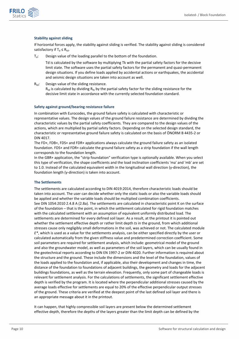
Stability against sliding
If horizontal forces apply, the stability against sliding is verified. The stability against sliding is considered satisfactory if Td ≤ Rtd.
Td: Design value of the loading parallel to the bottom of the foundation.
Td is calculated by the software by multiplying Tk with the partial safety factors for the decisive limit state. The software uses the partial safety factors for the permanent and quasi-permanent design situations. If you define loads applied by accidental actions or earthquakes, the accidental and seismic design situations are taken into account as well.
Rtd: Design value of the sliding resistance. Rtd is calculated by dividing Rtk by the partial safety factor for the sliding resistance for the decisive limit state in accordance with the currently selected foundation standard.
Safety against ground/bearing resistance failure
In combination with Eurocodes, the ground failure safety is calculated with characteristic or representative values. The design values of the ground failure resistance are determined by dividing the characteristic values by the partial safety coefficients. They are compared to the design values of the actions, which are multiplied by partial safety factors. Depending on the selected design standard, the characteristic or representative ground failure safety is calculated on the basis of ÖNORM B 4435-2 or DIN 4017. The FD+, FDB+, FDS+ and FDR+ applications always calculate the ground failure safety as an isolated foundation. FDS+ and FDR+ calculate the ground failure safety as a strip foundation if the wall length corresponds to the foundation length. In the GBR+ application, the "strip foundation" verification type is optionally available. When you select this type of verification, the shape coefficients and the load inclination coefficients 'ma' and 'mb' are set to 1.0. Instead of the calculated equivalent width in the longitudinal wall direction (y-direction), the foundation length (y-direction) is taken into account. The Settlements
The settlements are calculated according to DIN 4019:2014, therefore characteristic loads should be taken into account. The user can decide whether only the static loads or also the variable loads should be applied and whether the variable loads should be multiplied combination coefficients. See DIN 1054:2010 2.4.8 A (2.8a). The settlements are calculated in characteristic point K on the surface of the foundation – that is the point, in which the settlement calculated for rigid foundation matches with the calculated settlement with an assumption of equivalent uniformly distributed load. The settlements are determined for every defined soil layer. As a result, at the printout it is pointed out whether the settlement effective depth or rather limit depth ts in the ground, from which additional stresses cause only negligibly small deformations in the soil, was achieved or not. The calculated module E*, which is used as a value for the settlements analysis, can be either specified directly by the user or calculated automatically from the given stiffness value and predetermined correction coefficient. Some soil parameters are required for settlement analysis, which include: geometrical model of the ground and also the groundwater model, as well as parameters of the soil layers, which can be usually found in the geotechnical reports according to DIN EN 1997-2 or DIN 4020. Further information is required about the structure and the ground. These include the dimensions and the level of the foundation, values of the loads applied to the foundation and, if applicable, also their development and changes in time, the distance of the foundation to foundations of adjacent buildings, the geometry and loads for the adjacent buildings foundations, as well as the terrain elevation. Frequently, only some part of changeable loads is relevant for settlement analysis. For the calculations of settlements, the significant settlement effective depth is verified by the program. It is located where the perpendicular additional stresses caused by the average loads effective for settlements are equal to 20% of the effective perpendicular output stresses of the ground. These criteria are verified at the deepest point of the last defined soil layer and there is an appropriate message about it in the printout. It can happen, that highly compressible soil layers are present below the determined settlement effective depth, therefore the depths of the layers greater than the limit depth can be defined by the

FD + / FDB+
FRILO Software GmbH Page 11
program. The settlements are calculated according to DIN 4019:2014 (3) for a rigid foundation in the characteristic point (see DIN 4019:2014, figure 3). At first, the program calculates the settlement s, which consists of the immediate settlement s0 and the consolidation settlement s1. s = s0 + s1 The consolidation settlement is considered at the end of the consolidation according to DIN 4019:2014 12.2 and is determined for the point in time = 1 and set up in a table. Additionally, the increase of settlement in time until the estimated end of consolidation is graphically presented. Then the creep settlement for a value of ≥ 1 given by the user is calculated and that results in the total settlement value sges sges = s + s2
If eccentricities occur in the decisive superpositions or the significant load case for the settlement calculation, the additional settlement part Delta S is calculated. If there is a gaping joint, then the program reaches its applications limit for settlements calculations.

Isolated- / Block Foundation
Page 12 Software for structural calculation and design
Data entry The definition of properties and control parameters is done in the menu of the left screen section. You can check the effect of the entered values in the graphical representation on the right screen section.
Prior to the first entry, the units (cm, m ...) can be customized: FileProgram Options.
Wizard
The Wizard appears by default / automatically at startup, but can be switched off.
Input Options in the GUI
The input options in the GUI window are described in the document Basic operating instructions-PLUS.pdf.
Basic parameters Type of actions
- design values The loads are entered with their partial safety factors and reduced by the specified reducing factors in the soil engineering-specific verifications, if applicable.
- characteristic. The loads are specified with the characteristic (1.0-fold) value.
Reinforced concrete
Select the desired reinforced concrete standard:
See also Basis of calculation
Soil Engineering and Bearing failure
According to the selected reinforced concrete standard, the software selects the corresponding standards for soil engineering and bearing failure automatically.
Remarks
Click on the button, to enter your own comments to the system.
FD + / FDB+
FRILO Software GmbH Page 13
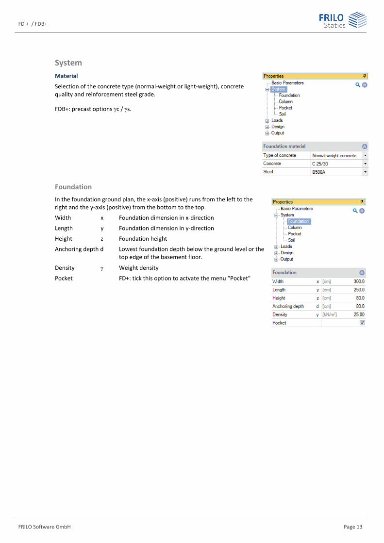
System Material
Selection of the concrete type (normal-weight or light-weight), concrete quality and reinforcement steel grade.
FDB+: precast options c / s.
Foundation In the foundation ground plan, the x-axis (positive) runs from the left to the right and the y-axis (positive) from the bottom to the top.
Width x Foundation dimension in x-direction
Length y Foundation dimension in y-direction
Height z Foundation height
Anchoring depth d Lowest foundation depth below the ground level or the top edge of the basement floor.
Density Weight density
Pocket FD+: tick this option to actvate the menu “Pocket”
Isolated- / Block Foundation
Page 14 Software for structural calculation and design
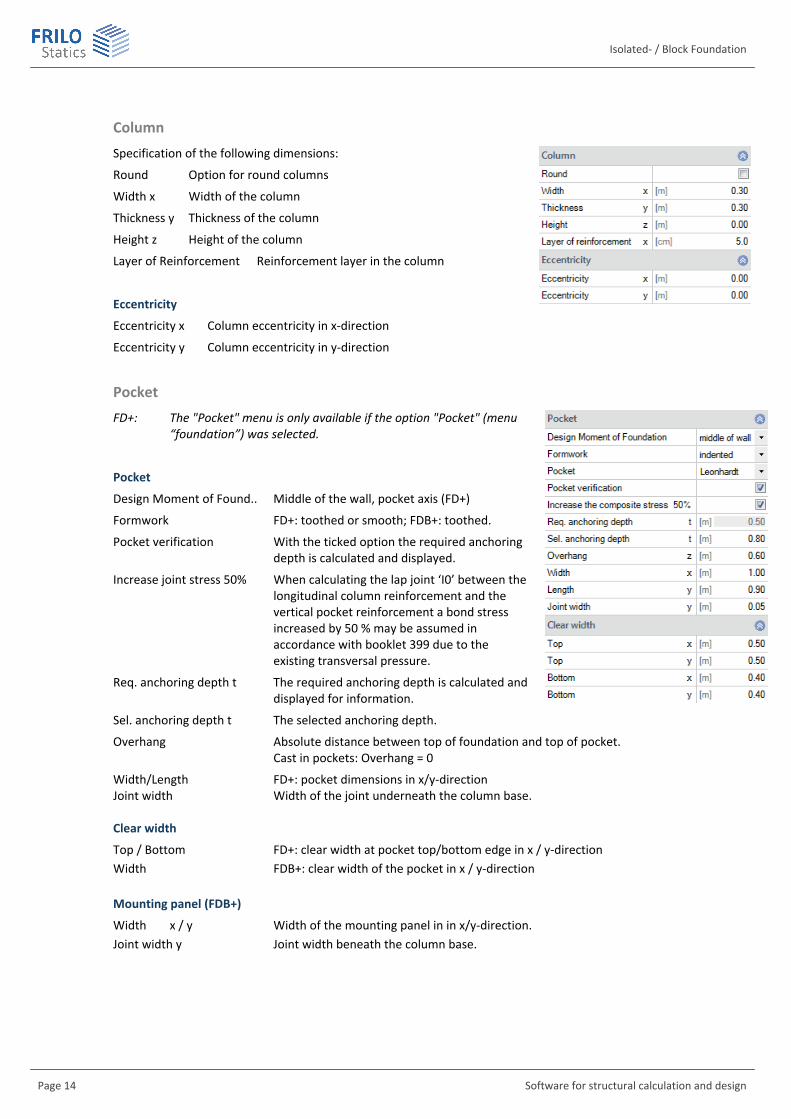
Column Specification of the following dimensions:
Round Option for round columns
Width x Width of the column
Thickness y Thickness of the column
Height z Height of the column
Layer of Reinforcement Reinforcement layer in the column
Eccentricity
Eccentricity x Column eccentricity in x-direction
Eccentricity y Column eccentricity in y-direction
Pocket FD+: The "Pocket" menu is only available if the option "Pocket" (menu
“foundation”) was selected.
Design Moment of Found.. Middle of the wall, pocket axis (FD+)
Formwork FD+: toothed or smooth; FDB+: toothed.
Pocket verification With the ticked option the required anchoring depth is calculated and displayed.
Increase joint stress 50% When calculating the lap joint ‘I0’ between the longitudinal column reinforcement and the vertical pocket reinforcement a bond stress increased by 50 % may be assumed in accordance with booklet 399 due to the existing transversal pressure.
Req. anchoring depth t The required anchoring depth is calculated and displayed for information.
Sel. anchoring depth t The selected anchoring depth.
Overhang Absolute distance between top of foundation and top of pocket. Cast in pockets: Overhang = 0
Width/Length FD+: pocket dimensions in x/y-direction Joint width Width of the joint underneath the column base. Clear width
Top / Bottom FD+: clear width at pocket top/bottom edge in x / y-direction Width FDB+: clear width of the pocket in x / y-direction Mounting panel (FDB+)
Width x / y Width of the mounting panel in in x/y-direction. Joint width y Joint width beneath the column base.
FD + / FDB+
FRILO Software GmbH Page 15
The program determines the required anchoring depth according to " Vorlesungen über Massivbau Teil 3 [Fritz Leonhardt] 16.3.3 page 228". It should be noted that the anchoring depth according to " Heft 411 [DAfStb] 7.1 Page 31" is 1.5 ds instead of 1.2 ds. Thereafter, a pocket depth of 1.5 times the column width is sufficient for existing friction to safely accommodate high bending stressed and reinforced columns. A pocket with an anchoring depth of 1.2 times the column width appears to achieve lower breaking loads, leads to slippage in the tensile reinforcement of the column and creates high strains in the stirrups. The anchoring depth depends on the referenced eccentricity e/d:
For e0.15
d< : TB 1.5 d= ◊
For e0.15
d> :
e 0.15dTB 1.5 d 0.5 d
1.85
-= ◊ + ◊ ◊
The required anchoring depth is limited by the program to 2 times the column width.
With smooth concrete surfaces, the minimum anchorage depth is increased by 40 %. Furthermore, the anchoring depth is defined by the program to at least 50 cm.
The calculated anchoring depth is displayed and you should select a value that is at least as high as the specified one.
Also smaller values can be entered if this is appropriate due to smaller moments. A corresponding note is displayed in the output.
Furthermore, it is possible to exclude the determination of the required anchoring depth and to define column reinforcement and pocket reinforcement in the reinforcement dialog and to control the calculation of the anchorage lengths and lap lengths via the output options "Reinforced concrete / Text Reinforcement" and, if applicable, "Anchoring details".
The clear widths must exceed the column dimensions by one centimetre at least. The minimum outer dimensions result from the selected clear dimensions plus 0.5 x column width for the walls (Booklet 399, page 66). The wall thickness must amount to 1/3 of the lowest pocket opening width at least. The distance of the column to the edge must be at least 10 cm at the upper pocket opening and 5 cm at the lower pocket opening. These geometrical conditions are verified during the definition of the column and adjusted, if required.
Isolated- / Block Foundation
Page 16 Software for structural calculation and design
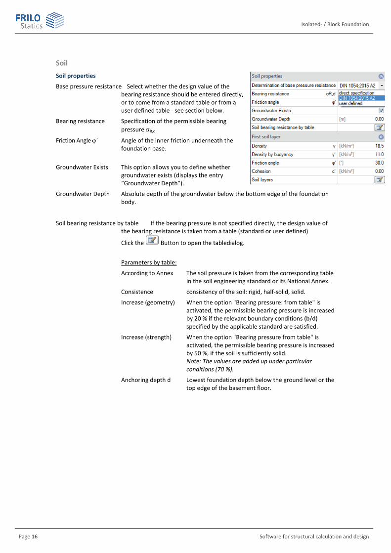
Soil Soil properties
Base pressure resistance Select whether the design value of the bearing resistance should be entered directly, or to come from a standard table or from a user defined table - see section below.
Bearing resistance Specification of the permissible bearing pressure R,d
Friction Angle ´ Angle of the inner friction underneath the foundation base.
Groundwater Exists This option allows you to define whether groundwater exists (displays the entry “Groundwater Depth”).
Groundwater Depth Absolute depth of the groundwater below the bottom edge of the foundation body.
Soil bearing resistance by table If the bearing pressure is not specified directly, the design value of the bearing resistance is taken from a table (standard or user defined)
Click the Button to open the tabledialog.
Parameters by table:
According to Annex The soil pressure is taken from the corresponding table in the soil engineering standard or its National Annex.
Consistence consistency of the soil: rigid, half-solid, solid.
Increase (geometry) When the option "Bearing pressure: from table" is activated, the permissible bearing pressure is increased by 20 % if the relevant boundary conditions (b/d) specified by the applicable standard are satisfied.
Increase (strength) When the option "Bearing pressure from table" is activated, the permissible bearing pressure is increased by 50 %, if the soil is sufficiently solid. Note: The values are added up under particular conditions (70 %).
Anchoring depth d Lowest foundation depth below the ground level or the top edge of the basement floor.
FD + / FDB+
FRILO Software GmbH Page 17
user defined table:
Generates a new entry
Rd Design value of the bearing resistance. This value should come from a geotechnical report and contain sufficient guarantees against ground failure and a sufficient limitation of settlements.
b, d Corresponding foundation width and anchoring depth.
First soil layer
In this section you can enter the values of the first soil layer.
Click the Button to open the dialog for additional soil layers below the sole.
Specific weight of the soil.
´ Specific weight of the soil layer under buoyancy. This value is only used if groundwater was defined (SystemSoil)
´ Friction angle of the soil in this layer.
c' Soil cohesion.
xU Thickness of the soil layer. Soil layers below 0.10 m cannot be defined.
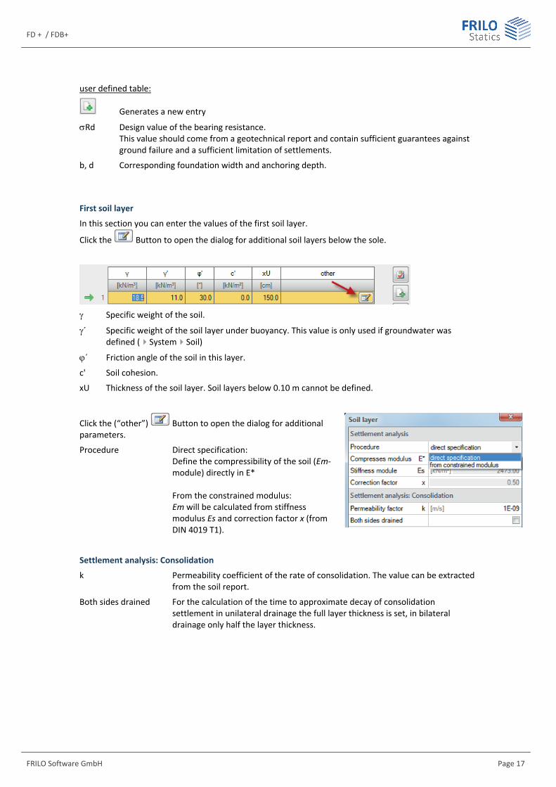
Click the (“other”) Button to open the dialog for additional parameters.
Procedure Direct specification: Define the compressibility of the soil (Em-module) directly in E* From the constrained modulus: Em will be calculated from stiffness modulus Es and correction factor x (from DIN 4019 T1).
Settlement analysis: Consolidation
k Permeability coefficient of the rate of consolidation. The value can be extracted from the soil report.
Both sides drained For the calculation of the time to approximate decay of consolidation settlement in unilateral drainage the full layer thickness is set, in bilateral drainage only half the layer thickness.
Isolated- / Block Foundation
Page 18 Software for structural calculation and design
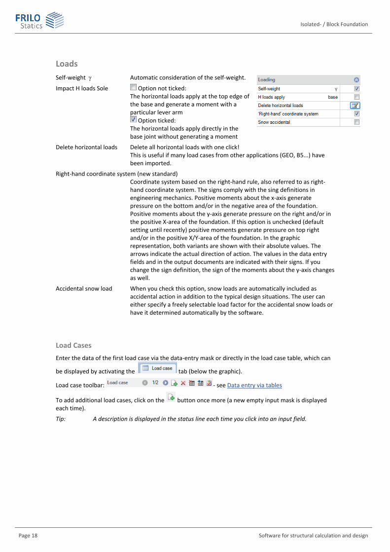
Loads Self-weight Automatic consideration of the self-weight.
Impact H loads Sole Option not ticked: The horizontal loads apply at the top edge of the base and generate a moment with a particular lever arm
Option ticked: The horizontal loads apply directly in the base joint without generating a moment
Delete horizontal loads Delete all horizontal loads with one click! This is useful if many load cases from other applications (GEO, B5...) have been imported.
Right-hand coordinate system (new standard) Coordinate system based on the right-hand rule, also referred to as right-hand coordinate system. The signs comply with the sing definitions in engineering mechanics. Positive moments about the x-axis generate pressure on the bottom and/or in the negative area of the foundation. Positive moments about the y-axis generate pressure on the right and/or in the positive X-area of the foundation. If this option is unchecked (default setting until recently) positive moments generate pressure on top right and/or in the positive X/Y-area of the foundation. In the graphic representation, both variants are shown with their absolute values. The arrows indicate the actual direction of action. The values in the data entry fields and in the output documents are indicated with their signs. If you change the sign definition, the sign of the moments about the y-axis changes as well.
Accidental snow load When you check this option, snow loads are automatically included as accidental action in addition to the typical design situations. The user can either specify a freely selectable load factor for the accidental snow loads or have it determined automatically by the software.
Load Cases Enter the data of the first load case via the data-entry mask or directly in the load case table, which can
be displayed by activating the tab (below the graphic).
Load case toolbar: - see Data entry via tables
To add additional load cases, click on the button once more (a new empty input mask is displayed each time).
Tip: A description is displayed in the status line each time you click into an input field.
FD + / FDB+
FRILO Software GmbH Page 19
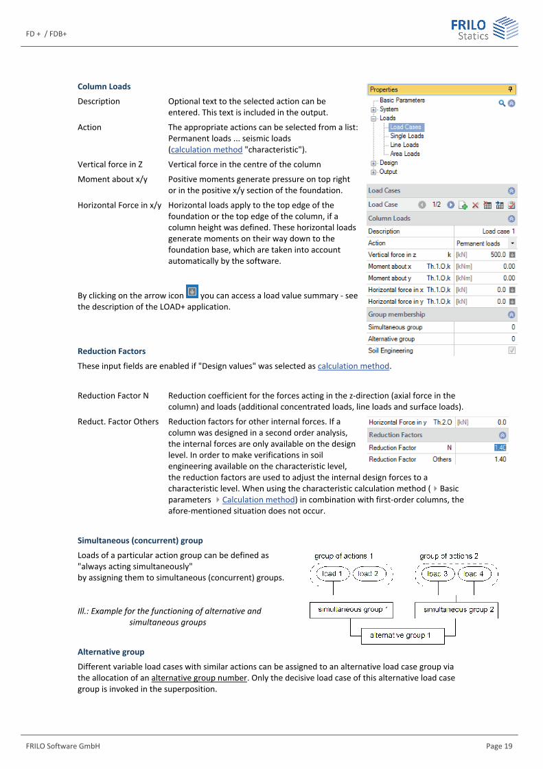
Column Loads
Description Optional text to the selected action can be entered. This text is included in the output.
Action The appropriate actions can be selected from a list: Permanent loads ... seismic loads (calculation method "characteristic").
Vertical force in Z Vertical force in the centre of the column
Moment about x/y Positive moments generate pressure on top right or in the positive x/y section of the foundation.
Horizontal Force in x/y Horizontal loads apply to the top edge of the foundation or the top edge of the column, if a column height was defined. These horizontal loads generate moments on their way down to the foundation base, which are taken into account automatically by the software.
By clicking on the arrow icon you can access a load value summary - see the description of the LOAD+ application.
Reduction Factors
These input fields are enabled if "Design values" was selected as calculation method.
Reduction Factor N Reduction coefficient for the forces acting in the z-direction (axial force in the column) and loads (additional concentrated loads, line loads and surface loads).
Reduct. Factor Others Reduction factors for other internal forces. If a column was designed in a second order analysis, the internal forces are only available on the design level. In order to make verifications in soil engineering available on the characteristic level, the reduction factors are used to adjust the internal design forces to a characteristic level. When using the characteristic calculation method (Basic parameters Calculation method) in combination with first-order columns, the afore-mentioned situation does not occur.
Simultaneous (concurrent) group
Loads of a particular action group can be defined as "always acting simultaneously" by assigning them to simultaneous (concurrent) groups. Ill.: Example for the functioning of alternative and
simultaneous groups
Alternative group
Different variable load cases with similar actions can be assigned to an alternative load case group via the allocation of an alternative group number. Only the decisive load case of this alternative load case group is invoked in the superposition.
Isolated- / Block Foundation
Page 20 Software for structural calculation and design
Foundation engineering
You can enable or disable the foundation engineering verifications for all load cases in the accidental design situation. In specific design situations such as ‘impact’, it can be reasonable to disregard a load case in the safety analyses of soil and foundation engineering (gaping joint, position stability simplified verification, ground failure, sliding, setting and buoyancy).
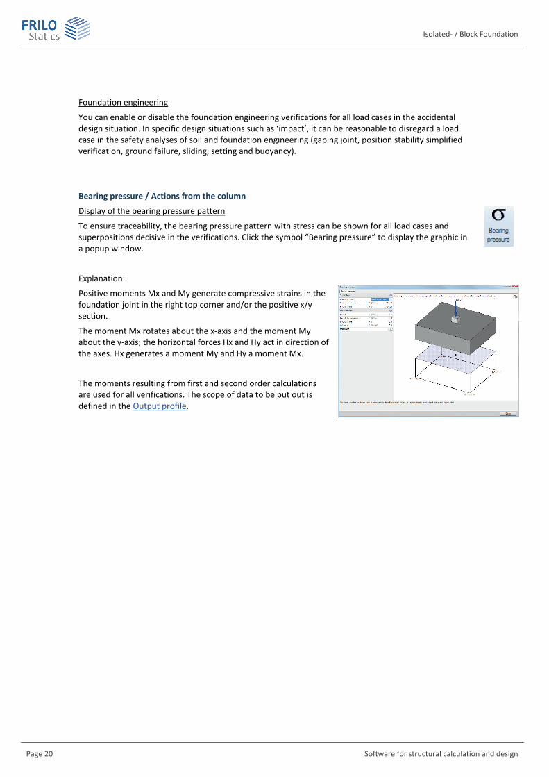
Bearing pressure / Actions from the column
Display of the bearing pressure pattern
To ensure traceability, the bearing pressure pattern with stress can be shown for all load cases and superpositions decisive in the verifications. Click the symbol “Bearing pressure” to display the graphic in a popup window.
Explanation:
Positive moments Mx and My generate compressive strains in the foundation joint in the right top corner and/or the positive x/y section.
The moment Mx rotates about the x-axis and the moment My about the y-axis; the horizontal forces Hx and Hy act in direction of the axes. Hx generates a moment My and Hy a moment Mx.
The moments resulting from first and second order calculations are used for all verifications. The scope of data to be put out is defined in the Output profile.

FD + / FDB+
FRILO Software GmbH Page 21
Single Loads
Define a new concentrated (single) load by activating the button (the corresponding input mask is displayed).
Activating the tab displays the "Single load table" giving an overview of the defined loads.
Toolbar: - see also Data entry via tables
Tip: A description is displayed in the status line each time you click into a particular input field.
In all LC: If you tick this option, the corresponding single load acts in all load cases.
Nz Value of the axial force of the additional single load. By clicking on the arrow icon you can access a load value summary - see the description of the LOAD+ application.
at ax/ay Position of the additional single load in x or y direction referenced to the foundation centre.
Active in LC Assignment of the additional single load to load cases.
Activating the button displays a dialog with the corresponding options.
Notes: If a single load is assigned to one or several load cases it acts only in combination with the load case(s. In the case of the calculation method design values single loads are processed with the corresponding reduction factors. Single loads that are not assigned to load cases are not taken into account in the calculation.
All verifications are referenced to the column loads. Additional single loads are defined only to check the effects on the bearing pressure, tilting, position stability, sliding and ground failure.
For the verification of punching shear resistance, the loads that apply in the area of the punching cone must be summarized to a resulting load, because the shear design would be unsafe otherwise.
With foundations for twin columns you should combine both columns to a single column instead of defining the second column as an additional single- or line load. Otherwise, you will obtain incorrect results in the verification of punching shear resistance .
Line Loads General operation as described under single loads.
In all LC: Option ticked: the load acts in all load cases
P1 Value at the begin of the line load
at x1/y1 Position of P1 relative to the foundation center
P2 Value at the end of the line load
at x2/y2 Position of P2 relative to the foundation center
Active in load case As described under single loads
Isolated- / Block Foundation
Page 22 Software for structural calculation and design
Area Loads Earth surcharge Height of the earth surcharge, if applicable. In combination with the weight
density , the soil load generates an area load on the foundation, which is taken into account in the calculation. Explanatory note: The earth surcharge load refers to the top edge of the foundation. If a wall, column, wall base or pocket exists, the earth surcharge load is reduced in accordance with the geometry of the structural component. Note: This value has nothing to do with the self-weight of the foundation.
Density k Weight density of a possible soil load.
Area Load q,k Additional area load on the foundation body. Explanatory note: The area load acts on the surface of the foundation. If a wall, column, wall base or pocket exists, the area load is reduced in accordance with the geometry of the structural component. If a top-mounted pocket exists, the area load also acts on the pocket, but not in the area of a column casted in the pocket. See the description of the option “Earth surcharge height“ for more information.
Active in load case Assignment of the additional area load to load cases.
Activating the button displays a dialog with the corresponding options.
FD + / FDB+
FRILO Software GmbH Page 23
Design / Verifications
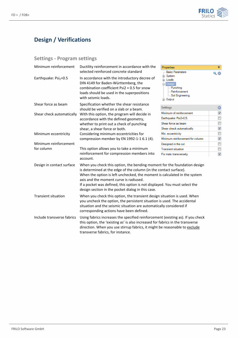
Settings - Program settings Minimum reinforcement Ductility reinforcement in accordance with the
selected reinforced concrete standard
Earthquake: Psi2=0.5 In accordance with the introductory decree of DIN 4149 for Baden-Württemberg, the combination coefficient Psi2 = 0.5 for snow loads should be used in the superpositions with seismic loads.
Shear force as beam Specification whether the shear resistance should be verified on a slab or a beam.
Shear check automatically With this option, the program will decide in accordance with the defined geometry, whether to print out a check of punching shear, a shear force or both.
Minimum eccentricity Considering minimum eccentricities for compression member by EN 1992-1-1 6.1 (4).
Minimum reinforcement for column This option allows you to take a minimum
reinforcement for compression members into account.
Design in contact surface When you check this option, the bending moment for the foundation design is determined at the edge of the column (in the contact surface). When the option is left unchecked, the moment is calculated in the system axis and the moment curve is radiused. If a pocket was defined, this option is not displayed. You must select the design section in the pocket dialog in this case.
Transient situation When you check this option, the transient design situation is used. When you uncheck the option, the persistent situation is used. The accidental situation and the seismic situation are automatically considered if corresponding actions have been defined.
Include transverse fabrics Using fabrics increases the specified reinforcement (existing as). If you check this option, the ‘existing as’ is also increased for fabrics in the transverse direction. When you use stirrup fabrics, it might be reasonable to exclude transverse fabrics, for instance.

Isolated- / Block Foundation
Page 24 Software for structural calculation and design
Punching The Eurocodes provide several methods for the punching shear analysis. In accordance with DIN 1045, constant -coefficients are used in the punching shear analysis.
Column type: Selection of the type of column: - automatically - inner column, - outer (edge) column in the x- or y-direction and - corner column. This setting affects the way how the control perimeters are generated.
If you activate the "Automatic" option, the type of column is determined as specified by DIN 1045-1:2008, figure 41 on page 105.
inner column edge column corner column
Determination Selection how to define the punching shear coefficient: - ductile shear force distribution - sector model - constant values - user-defined value In combination with plastic shear stress distribution, the selected column type is used for the calculation of the coefficient in order to take dynamically unbalanced loading in the critical perimeter into account. The static moments of the line of gravity of the critical perimeter are calculated using the set of formulae specified in Booklet 600:2012, table H6.4, page 96. The -value that is used subsequently in the punching shear analysis results from this calculation. When using the sector model, the selected column type is not of importance. The application program checks automatically which shape of critical perimeter produces the shortest perimeter length and whether the perimeter intersects the foundation edge in its shortest version. The punching shear analysis is based on the maximum stress of the decisive sector. See Notes concerning the sector model. For constant values, the -value specified in the design code for the selected column type is used.
User-defined: the "Value of punching/Punching shear coefficient " entry field is enabled.
Punching shear coefficient : You can manually set the coefficient for dynamically unbalanced loading in the
critical perimeter. It is used in combination with the selected column type in the punching shear analysis with constant factors.
Calculation as per: This option is only enabled in combination with DIN 1045-1. Selection of the desired punching shear analysis: in accordance with DIN 1045-1 or DAfStb* Booklet. When selecting Booklet 525, a calculation as a compact foundation can be imposed.
Load factor: The design value of the shear force in the punching shear analysis is multiplied with this factor. It allows you to increase the punching shear load in order to take dynamically unbalanced flexural loading into account, for instance.
FD + / FDB+
FRILO Software GmbH Page 25
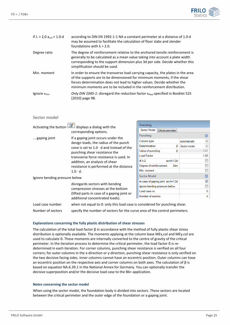
if > 2,0 acrit = 1.0d according to DIN EN 1992-1-1 NA a constant perimeter at a distance of 1.0d may be assumed to facilitate the calculation of floor slabs and slender foundations with λ > 2.0.
Degree ratio The degree of reinforcement relative to the anchored tensile reinforcement is generally to be calculated as a mean value taking into account a plate width corresponding to the support dimension plus 3d per side. Decide whether this simplification should be used.
Min. moment In order to ensure the transverse load carrying capacity, the plates in the area of the supports are to be dimensioned for minimum moments, if the shear forces determination does not lead to higher values. Decide whether the minimum moments are to be included in the reinforcement distribution.
Ignore κRed Only DIN 1045-1: disregard the reduction factor Red specified in Booklet 525 [2010] page 98.
Sector model
Activating the button displays a dialog with the corresponding options.
... gaping joint If a gaping joint occurs under the design loads, the radius of the punch cone is set to 1.0 d and instead of the punching shear resistance the transverse force resistance is used. In addition, an analysis of shear resistance is performed at the distance 1.0 d.
Ignore bending pressure below
disregards sectors with bending compression stresses at the bottom (lifted parts in case of a gaping joint or additional concentrated loads).
Load case number when not equal to 0: only this load case is considered for punching shear.
Number of sectors specify the number of sectors for the curve area of the control perimeters.
Explanations concerning the fully plastic distribution of shear stresses
The calculation of the total load factor β in accordance with the method of fully plastic shear stress distribution is optionally available. The moments applying at the column base MEx,col and MEy,col are used to calculate ẞ. These moments are internally converted to the centre of gravity of the critical perimeter. In the iteration process to determine the critical perimeter, the load factor ẞ is re-determined in each iteration. For corner columns, punching shear resistance is verified on all four corners; for outer columns in the x-direction or y-direction, punching shear resistance is only verified on the two decisive facing sides. Inner columns cannot have an eccentric position. Outer columns can have an eccentric position on the respective axis and corner columns on both axes. The calculation of β is based on equation NA.6.39.1 in the National Annex for Germany. You can optionally transfer the decisive superposition and/or the decisive load case to the B6+ application.
Notes concerning the sector model
When using the sector model, the foundation body is divided into sectors. These sectors are located between the critical perimeter and the outer edge of the foundation or a gaping joint.

Isolated- / Block Foundation
Page 26 Software for structural calculation and design
The stress over the sector section bordering the perimeter and over the statically effective height is calculated from the resulting shear force in the sector.
The maximum stress in a sector at the perimeter border divided by the average stress at the perimeter gives the -coefficient, which is provided here just for information.
The punching shear resistance is verified with the maximum stress at the perimeter. The maximum stress is obtained by dividing the shear force of the decisive sector by the length of the sector section bordering the perimeter and by the statically effective height of the foundation.
The lowest possible value resulting from the calculation is = 1.0.
The minimum value may result if the column has a circular cross-section, the foundation is loaded double-symmetrically and has a circular base area. Relevant standards assume a minimum value of = 1.1 because a completely symmetrical case as previously described cannot occur in practice according to these codes. Therefore, FD+ always uses a -value of 1.1 minimum.
Handling of the sector model in the application program
First, the geometry of the sectors is calculated.
The user can pre-set the number of sectors per quadrant in a range of 1 to 100. The default in FD+ is four sectors for each corner of the column.
The sectors in the corner area have constant inner angles. Only in the special case of three sectors per corner area, angles of 33.75° + 22.5° + 33.75° = 90° are used in Germany as recommended in the comment to Eurocode 2.
FD + / FDB+
FRILO Software GmbH Page 27
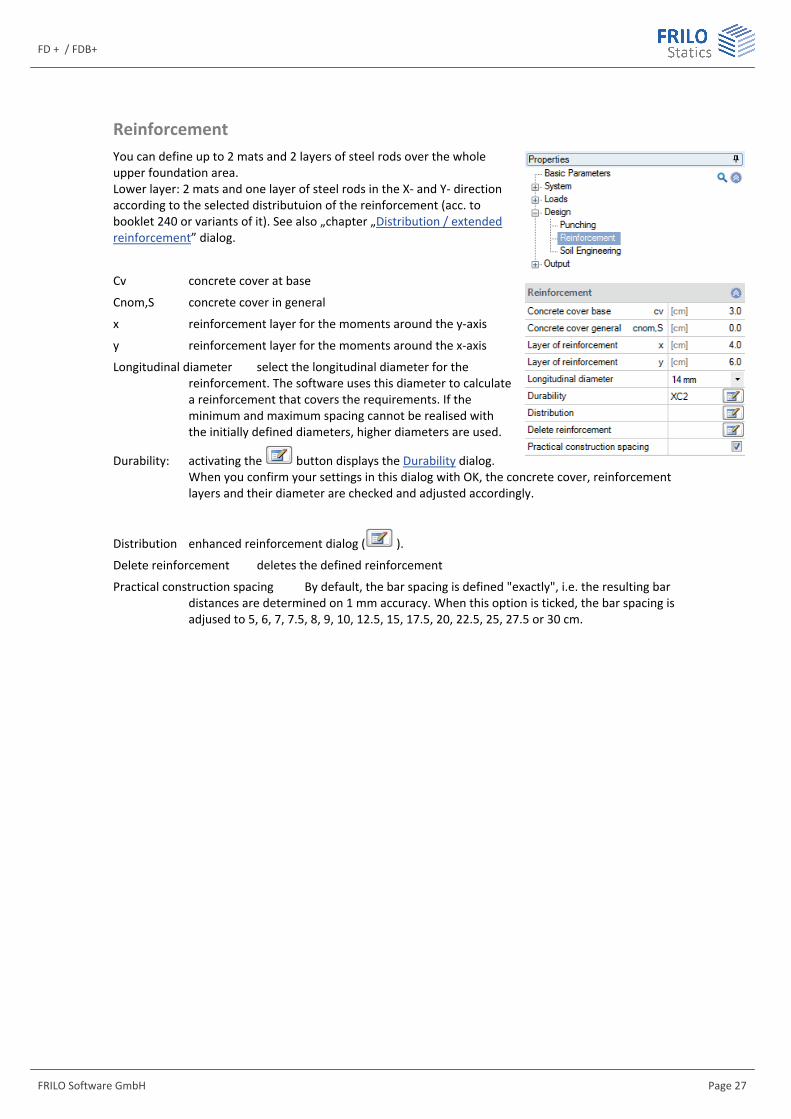
Reinforcement You can define up to 2 mats and 2 layers of steel rods over the whole upper foundation area. Lower layer: 2 mats and one layer of steel rods in the X- and Y- direction according to the selected distributuion of the reinforcement (acc. to booklet 240 or variants of it). See also „chapter „Distribution / extended reinforcement” dialog.
Cv concrete cover at base
Cnom,S concrete cover in general
x reinforcement layer for the moments around the y-axis
y reinforcement layer for the moments around the x-axis
Longitudinal diameter select the longitudinal diameter for the reinforcement. The software uses this diameter to calculate a reinforcement that covers the requirements. If the minimum and maximum spacing cannot be realised with the initially defined diameters, higher diameters are used.
Durability: activating the button displays the Durability dialog. When you confirm your settings in this dialog with OK, the concrete cover, reinforcement layers and their diameter are checked and adjusted accordingly.
Distribution enhanced reinforcement dialog ( ).
Delete reinforcement deletes the defined reinforcement
Practical construction spacing By default, the bar spacing is defined "exactly", i.e. the resulting bar distances are determined on 1 mm accuracy. When this option is ticked, the bar spacing is adjused to 5, 6, 7, 7.5, 8, 9, 10, 12.5, 15, 17.5, 20, 22.5, 25, 27.5 or 30 cm.
Isolated- / Block Foundation
Page 28 Software for structural calculation and design
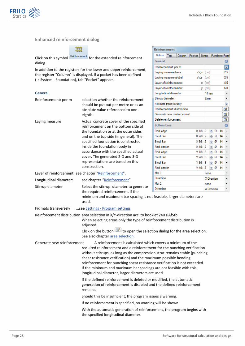
Enhanced reinforcement dialog
Click on this symbol for the extended reinforcement dialog.
In addition to the registers for the lower and upper reinforcement, the register "Column" is displayed. If a pocket has been defined (System - Foundation), tab "Pocket" appears.
General
Reinforcement: per m selection whether the reinforcement should be put out per metre or as an absolute value referenced to one eighth.
Laying measure Actual concrete cover of the specified reinforcement on the bottom side of the foundation or at the outer sides and on the top side (in general). The specified foundation is constructed inside the foundation body in accordance with the specified actual cover. The generated 2-D and 3-D representations are based on this construction.
Layer of reinforcement see chapter “Reinforcement”.
Longitudinal diameter: see chapter “Reinforcement”.
Stirrup diameter Select the stirrup diameter to generate the required reinforcement. If the minimum and maximum bar spacing is not feasible, larger diameters are used.
Fix mats transversely ...see Settings - Program settings
Reinforcement distribution area selection in X/Y-direction acc. to booklet 240 DAfStb. When selecting areas only the type of reinforcement distribution is adjusted. Click on the button to open the selection dialog for the area selection. See also chapter area selection.
Generate new reinforcement A reinforcement is calculated which covers a minimum of the required reinforcement and a reinforcement for the punching verification without stirrups, as long as the compression strut remains stable (punching shear resistance verification) and the maximum possible bending reinforcement for punching shear resistance verification is not exceeded. If the minimum and maximum bar spacings are not feasible with this longitudinal diameter, larger diameters are used.
If the defined reinforcement is deleted or modified, the automatic generation of reinforcement is disabled and the defined reinforcement remains.
Should this be insufficient, the program issues a warning.
If no reinforcement is specified, no warning will be shown.
With the automatic generation of reinforcement, the program begins with the specified longitudinal diameter.
FD + / FDB+
FRILO Software GmbH Page 29
With a new generation of the reinforcement an automatic optimization is executed.
Delete reinforcement deletes the defined reinforcement. Only the required reinforcement will be taken into account.
Bottom / Top base
Rod ... X/Y definition of number (1. column) and diameter (2. column) of rods/steal bars
Mat 1/2, Direction Selection of rebar mats in x/y-direction.
Bar graphs: see adjacent illustration: As per 1/8th-region
In this graphic you can see the amount of defined (blue) an required (red) reinforcement. Therefore click on the 2D/3D-symbol.
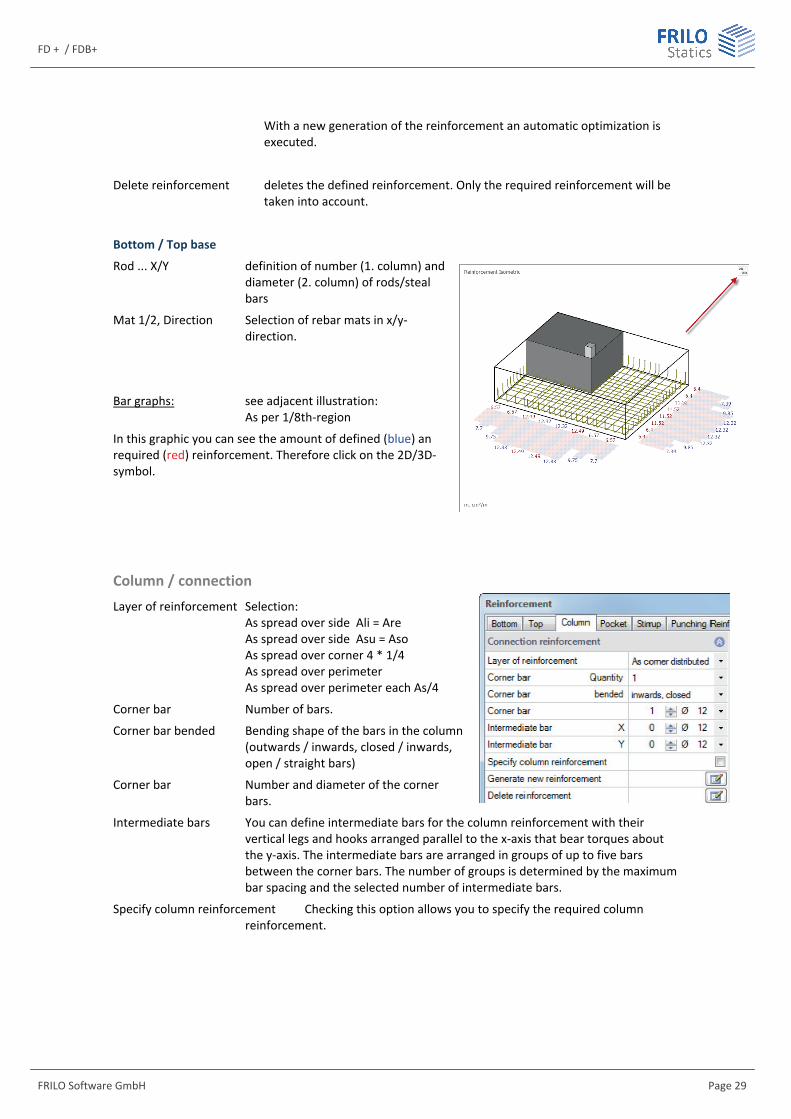
Column / connection Layer of reinforcement Selection:
As spread over side Ali = Are As spread over side Asu = Aso As spread over corner 4 * 1/4 As spread over perimeter As spread over perimeter each As/4
Corner bar Number of bars.
Corner bar bended Bending shape of the bars in the column (outwards / inwards, closed / inwards, open / straight bars)
Corner bar Number and diameter of the corner bars.
Intermediate bars You can define intermediate bars for the column reinforcement with their vertical legs and hooks arranged parallel to the x-axis that bear torques about the y-axis. The intermediate bars are arranged in groups of up to five bars between the corner bars. The number of groups is determined by the maximum bar spacing and the selected number of intermediate bars.
Specify column reinforcement Checking this option allows you to specify the required column reinforcement.
Isolated- / Block Foundation
Page 30 Software for structural calculation and design
Pocket reinforcement Note: some parameters only apply to FD+ or to FDB+, not to both.
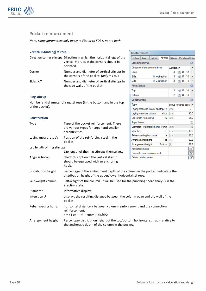
Vertical (Standing) stirrup
Direction corner stirrups Direction in which the horizontal legs of the vertical stirrups in the corners should be oriented.
Corner Number and diameter of vertical stirrups in the corners of the pocket. (only in FD+)
Sides X,Y Number and diameter of vertical stirrups in the side walls of the pocket.
Ring stirrup
Number and diameter of ring stirrups (in the bottom and in the top of the pocket).
Construction
Type Type of the pocket reinforcement. There are various types for larger and smaller eccentricities.
Laying measure... cV Position of the reinforcing steel in the pocket
Lap length of ring stirrups Lap length of the ring stirrups themselves.
Angular hooks check this option if the vertical stirrup should be equipped with an anchoring hook.
Distribution height percentage of the embedment depth of the column in the pocket, indicating the distribution height of the upper/lower horizontal stirrups.
Self-weight column Self-weight of the column. It will be used for the punching shear analysis in the erecting state.
Diameter Informative display.
Interstice tF displays the resulting distance between the column edge and the wall of the pocket.
Rebar spacing horiz. horizontal distance a between column reinforcement and the connection reinforcement. a = d1,col + tF + cnom + ds,fd/2
Arrangement height Percentage distribution height of the top/bottom horizontal stirrups relative to the anchorage depth of the column in the pocket.
FD + / FDB+
FRILO Software GmbH Page 31
Area selection
Areas in the x- and y-directions
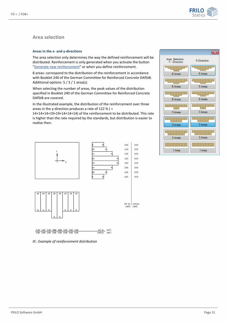
The area selection only determines the way the defined reinforcement will be distributed. Reinforcement is only generated when you activate the button "Generate new reinforcement" or when you define reinforcement.
8 areas: correspond to the distribution of the reinforcement in accordance with Booklet 240 of the German Committee for Reinforced Concrete DAfStB. Additional options: 5 / 3 / 1 area(s).
When selecting the number of areas, the peak values of the distribution specified in Booklet 240 of the German Committee for Reinforced Concrete DAfStB are covered.
In the illustrated example, the distribution of the reinforcement over three areas in the y-direction produces a rate of 122 % ( = 14+14+14+19+19+14+14+14) of the reinforcement to be distributed. This rate is higher than the rate required by the standards, but distribution is easier to realise then.
Ill.: Example of reinforcement distribution
Isolated- / Block Foundation
Page 32 Software for structural calculation and design
Notes concerning the selected reinforcement Reinforcement objects
The reinforcement used in the software can include any number of reinforcement objects. The software generates reinforcement objects based on the details entered by the user. Reinforcement objects can be rebars of a particular diameter and in a particular quantity that are distributed over an area with a particular bar spacing, for instance. The same can apply to reinforcing fabric.
Reinforcement ratios
The software calculates the absolute reinforcement quantities in eighth-part stripes in the x- and y-directions of the foundation body in accordance with the requirements specified by Booklet 240 of the German Committee for Reinforced Concrete DAfStB. In this calculation, the individual rebars in an eighth-part area are NOT added up but the quantity of reinforcing steel per metre of the reinforcement object in the area of one eighth is added up. See also the following calculation example.
Calculation example
See the illustration on the previous page.
The eighth-part area of a foundation with a width of 2 m has a width of 25 cm. The reinforcement object defined in this area consists of 10 bars with a diameter of 14 mm each. The spacing of the bars from axis to axis is 10 cm. The object covers a total width of 1 m. The width from the first bar to the last amounts to 90 cm. 5 cm on each side (half the bar spacing of 10 cm) must be added because of the affected width of the first and last reinforcement bar of the item. The total width is consequently 1 m. This object produces the following reinforcement portion:
As = [1.4 cm 1.4 cm π / 4 ] 10 bars / 1 m = 15.4 cm²/m.
Due to the edge distance of this object of 17.5 cm (rounded to 0.18 m), it extends only 12.5 cm into the eighth-part with a width of 25 cm. The value of 12.5 cm is obtained by deducting the affected width of the last rebar of 5 cm due to a bar spacing of 10 cm from the edge distance: 17.5 cm – 5 cm = 12.5 cm. Therefore, only a reinforcement portion of 15.4 cm²/m 0.125 m = 1.92 cm² results for this object in the eighth part.
The existing and required reinforcement quantities in the eighth parts are represented graphically and in the form of text in the data entry and output sections, optionally in cm² or cm²/m – see ReinforcementDistribution.
The reinforcement in the eighth parts is also used in the shear force resistance verification and in the punching shear analysis. All reinforcement quantities in the eighth parts of the examined perimeters are added up and converted to ratios. If the existing reinforcement quantity exceeds the required quantity, it is used instead. The resulting reinforcement ratios are limited by the maximally permissible reinforcement ratios for the shear force and punching shear analyses.
FD + / FDB+
FRILO Software GmbH Page 33
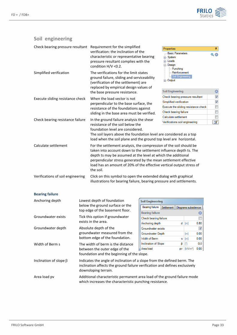
Soil engineering Check bearing pressure resultant Requirement for the simplified
verification: the inclination of the characteristic or representative bearing pressure resultant complies with the condition H/V <0.2.
Simplified verification The verifications for the limit states ground failure, sliding and serviceability (verification of the settlement) are replaced by empirical design values of the base pressure resistance.
Execute sliding resistance check When the load vector is not perpendicular to the base surface, the resistance of the foundations against sliding in the base area must be verified.
Check bearing resistance failure In the ground failure analysis the shear resistance of the soil below the foundation level are considered. The soil layers above the foundation level are considered as a top load when the soil plane and the ground top level are horizontal.
Calculate settlement For the settlement analysis, the compression of the soil should be taken into account down to the settlement influence depth ts. The depth ts may be assumed at the level at which the additional perpendicular stress generated by the mean settlement effective load has an amount of 20% of the effective vertical output stress of the soil.
Verifications of soil engineering Click on this symbol to open the extended dialog with graphical illustrations for bearing failure, bearing pressure and settlements.
Bearing failure
Anchoring depth Lowest depth of foundation below the ground surface or the top edge of the basement floor.
Groundwater exists Tick this option if groundwater exists in the area.
Groundwater depth Absolute depth of the groundwater measured from the bottom edge of the foundation.
Width of Berm s The width of berm is the distance between the outer edge of the foundation and the beginning of the slope.
Inclination of slope Indicates the angle of inclination of a slope from the defined berm. The inclination affects the ground failure verification and defines exclusively downsloping terrain.
Area load pv Additional characteristic permanent area load of the ground failure mode which increases the characteristic punching resistance.

Isolated- / Block Foundation
Page 34 Software for structural calculation and design
Settlement
Calculate settlement See page before.
Settlement Settlements can be calculated with permanent loads or with permanent and variable loads. You can use combination coefficients for variable loads in characteristic load cases. See also DIN 1054:2010 2.4.8 A (2.8a).

FD + / FDB+
FRILO Software GmbH Page 35
Pocket (Sleeve) foundation
Two different calculation methods are available for the calculation of a sleeve with rough formwork:
Schlaich/Schäfer: “Konstruieren im Stahlbetonbau”; BK 2001/2 4.7.3 analogously to “Beispiele zur Bemessung nach Eurocode 2” Volume 1, Chapter 12
Leonhardt and Mönning: "Vorlesungen über Massivbau”, Part 3, page 227 and subsequent pages, analogously to “Beispiele zur Bemessung nach DIN 1045“
The following calculation method is available for the calculation of a sleeve with smooth formwork:
Leonhardt and Mönning: "Vorlesungen über Massivbau”, Part 3, page 227 and subsequent pages, analogously to “Beispiele zur Bemessung nach DIN 1045“
Calculation in accordance with "Beispiele zur Bemessung nach Eurocode 2", Volume 1, Chapter 12: The prerequisite for the calculation based on this method is that the column base, the sleeve filling concrete and the foundation interact like a monolithic structure. The moment and the longitudinal forces generated by the column are transferred via vertical shear stresses to the sleeve. To ensure this, the sleeve and the column need profiling of at least 10 mm. The filling concrete must have the same quality as the foundation concrete. If the required embedment depth is calculated with the help of the anchoring depths and/or the lap lengths, the value of 1.5 times the column width prescribed by DIN EN 1992-1-1/NA 10.9.6.3 (1) is on the safe side and therefore recommendable. The bending design in connection with the sleeve can be performed in the sleeve axis with rounding of the moment or in the centre of the sleeve wall or in the contact surface of the sleeve.
The calculation is based on the following framework model:
The following verifications are performed:
Introduction of the shear force VEd into the sleeve via the tensile force T2 horizontal stirrups
T2 = VEd
Req.As,horizontal = T2/fyd
Isolated- / Block Foundation
Page 36 Software for structural calculation and design
Absorption of the tensile force T1 caused by Fs and T2 vertical stirrups
Portion T1 from deflection of T2
t = sleeve embedment depth plus joint underneath the column
aw = spacing of the sleeve wall axes
T1 =T2*t/aw = portion of the tensile force due to the deflection of T2
dw = sleeve wall thickness
tf = joint between the sleeve wall and the column
d1 = centre of gravity of the reinforcement in the column
a = d1 + tf + dw/2=offset of the reinforcement
z = internal lever arm of the column reinforcement
Req.As,F = assumed column reinforcement
Fs = req.As,F * fyd = tensile force of the column
T1 = Fs*z/(a+z) + T2*t/aw
Req. As,z = T1 / fyd
Absorption of the tensile force T3 due to the expansion effect of the compression struts C1 and C2 horizontal stirrups
tanΘ = [exist.l0-0.5(l0,z1+l0,z2)]/a
T3 = C1 = T1 / tan θ
Req.As,horizontal = T3/fyd
The required horizontal stirrups are to be distributed over the lap lengths of the vertical stirrups l0.
FD + / FDB+
FRILO Software GmbH Page 37
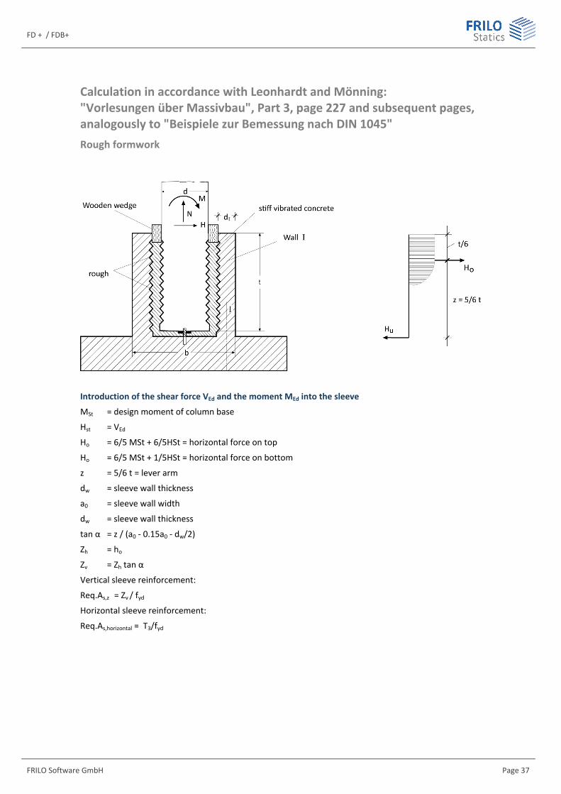
Calculation in accordance with Leonhardt and Mönning: "Vorlesungen über Massivbau", Part 3, page 227 and subsequent pages, analogously to "Beispiele zur Bemessung nach DIN 1045" Rough formwork
Introduction of the shear force VEd and the moment MEd into the sleeve
MSt = design moment of column base
Hst = VEd
Ho = 6/5 MSt + 6/5HSt = horizontal force on top
Ho = 6/5 MSt + 1/5HSt = horizontal force on bottom
z = 5/6 t = lever arm
dw = sleeve wall thickness
a0 = sleeve wall width
dw = sleeve wall thickness
tan α = z / (a0 - 0.15a0 - dw/2)
Zh = ho
Zv = Zh tan α
Vertical sleeve reinforcement:
Req.As,z = Zv / fyd
Horizontal sleeve reinforcement:
Req.As,horizontal = T3/fyd
Isolated- / Block Foundation
Page 38 Software for structural calculation and design
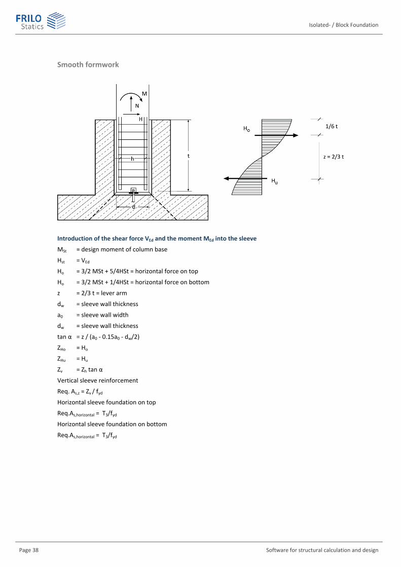
Smooth formwork
Introduction of the shear force VEd and the moment MEd into the sleeve
MSt = design moment of column base
Hst = VEd
Ho = 3/2 MSt + 5/4HSt = horizontal force on top
Ho = 3/2 MSt + 1/4HSt = horizontal force on bottom
z = 2/3 t = lever arm
dw = sleeve wall thickness
a0 = sleeve wall width
dw = sleeve wall thickness
tan α = z / (a0 - 0.15a0 - dw/2)
ZHo = Ho
ZHu = Hu
Zv = Zh tan α
Vertical sleeve reinforcement
Req. As,z = Zv / fyd
Horizontal sleeve foundation on top
Req.As,horizontal = T3/fyd
Horizontal sleeve foundation on bottom
Req.As,horizontal = T3/fyd

FD + / FDB+
FRILO Software GmbH Page 39
Anchorage of the tension rods in the column for the tensile force Fs The required anchorage length for the tension and compression bars of the column reinforcement is calculated and compared to the existing anchoring length. The existing anchoring length is determined by the embedment depth minus the actual concrete cover. It is assumed that the column reinforcement can also be a compressive reinforcement. In combination with the German standard, hooks, angular hooks and loops are not allowed. Therefore, straight bars are used in the calculation, α1 = 1.0.
lb,rqd = (ds/4) / (σsd/fbd) = basic value of the anchoring length
lbd,erf. =α1 * lb,rqd * (As,req.. / As,exist.) = required anchorage length
lbd,vorh. = t – cv = existing anchorage length
Anchorage of vertical stirrups in the sleeve The required anchorage length of the vertical stirrups in the sleeve is calculated and then compared to the existing anchorage length which is obtained by deducting the concrete cover from the foundation height.
Lapping of the perpendicular stirrups and the vertical tensile reinforcement in the column
The lap lengths of the column reinforcement and the vertical sleeve reinforcement are calculated. The required lap length is decisive in this connection. When calculating the lap length of the column reinforcement, the fact that only the tensile force portion that is transferred via the compression strut C1 is transmitted via the lap joint is taken into account. When calculating the lap joint l0 a bond stress increased by 50 % is assumed in accordance with Booklet 399 due to the existing transversal pressure.
Output
If you have checked the options “Text on reinforcement” and “Details of anchorage” in the in the Scope of the output menu, the equations and intermediate results of the sleeve calculation are put out.

Isolated- / Block Foundation
Page 40 Software for structural calculation and design
Block Foundation
Block foundations can be calculated in program “FDB+”.
You can access the program FDB+ directly or from the program Isolated Foundation – FD+ under the item “Associated Programs” (assuming that the FDB+ program is installed on your computer).
The calculation is performed in accordance with the method described in "Deutscher Beton- und Bautechnik-Verein E.V. - Beispiele zur Bemessung nach Eurocode 2".
A block foundation is a foundation, in which the pocket is embedded.
A block foundation is characterized by an appropriate connection between the bottom part of the column and the walls of the pocket, due to which a monolithic work of the foundation with the column can be assumed.
The flexural design of a block foundation, in contrary to an isolated foundation, is conducted for a cross-section along the edge of a column. The resulting flexural design is made according to Heft 240, T 2.10. The task is made separately for x and y directions. Connection reinforcement in the foundation, as well as anchorage and overlapping lengths of the column reinforcement and the connection reinforcement are determined.
Fig.: Determination of the vertical stirrups Asv with tensile force Z1, determination of the horizontal stirrups Ash with tensile force Z2
The punching shear analysis is performed for:
- the erecting stage (for the self-weight of the column, which is applied during assembly)
- the final stage
FD + / FDB+
FRILO Software GmbH Page 41
Output
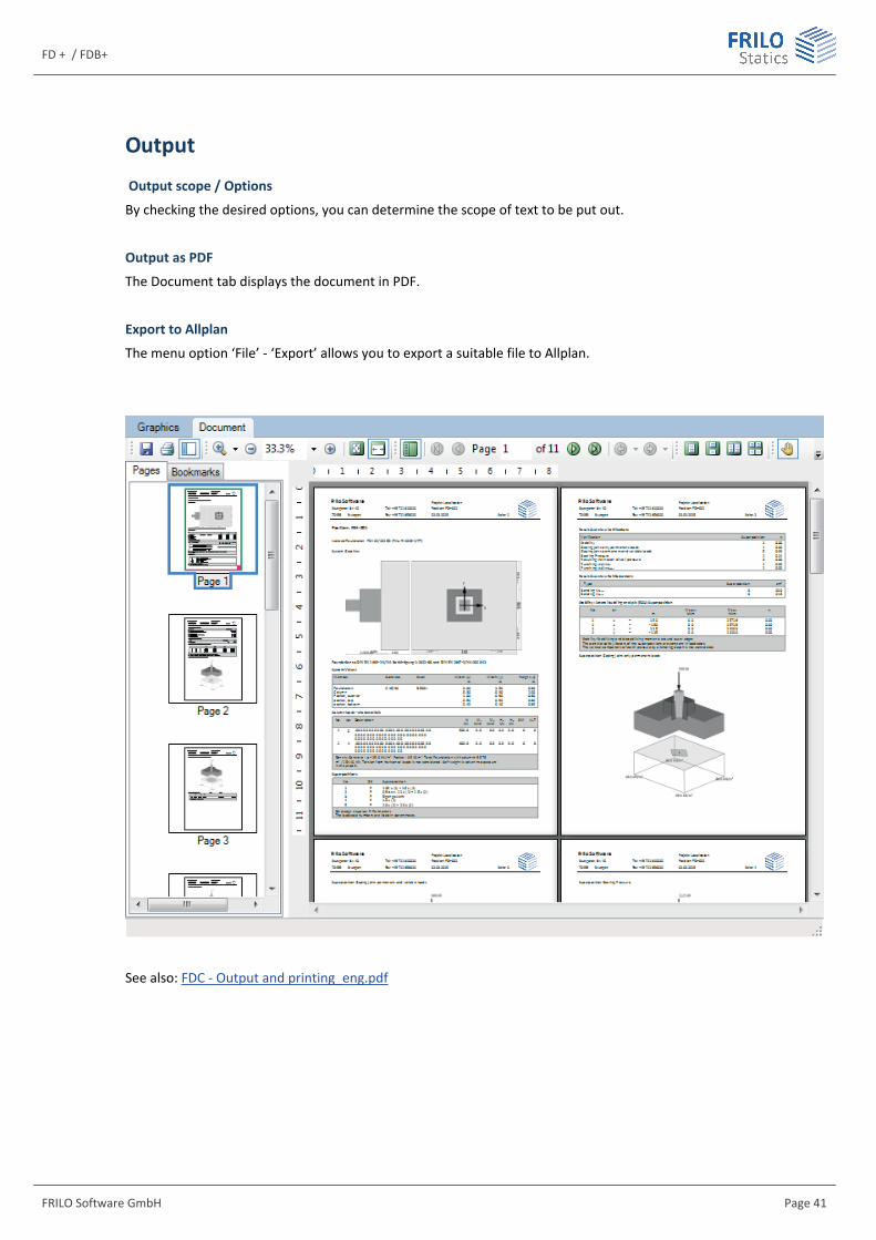
Output scope / Options
By checking the desired options, you can determine the scope of text to be put out.
Output as PDF
The Document tab displays the document in PDF.
Export to Allplan
The menu option ‘File’ - ‘Export’ allows you to export a suitable file to Allplan.
See also: FDC - Output and printing_eng.pdf

Isolated- / Block Foundation
Page 42 Software for structural calculation and design
Explanatory notes on the output of the results (table)
Output of the reinforcement
Note: The existing reinforcement is not the result of an addition of individual rebars. It is determined by the rebar diameter and the bar spacing per m of the reinforcement area (e.g. the eighth part). The eighth parts at the edges of the foundation are not considered with their full width because of the concrete cover. Therefore, the reinforcement totals in the areas close to the edges may differ even though the reinforcement per m is the same. In the example, there is a difference in the x-direction between the existing reinforcement (As = 3.61 cm²) in the first eighth part and in the second and third eighth parts (3.67 cm²).
The reinforcement is put out in a table. If no type of reinforcement is selected, the existing reinforcement is put out. In the upper table section, the coordinates and the widths of the individual areas are indicated. In the middle part of the table, the selected rebars and fabrics are specified. In the lower part of the table, the required and the existing reinforcement are represented in cm² and cm²/m.
If detailed presetting was selected, a first table gives an overview of the required and the existing reinforcement in each eighth part. In a second table underneath, the used reinforcement objects are listed.
Evaluation of the results The flexural reinforcement is calculated for the greatest Mx and My moments and the required reinforcement referenced to the foundation width is put out.
The decisive flexural moments are calculated in the following expressions: For centrically loaded foundations, the design moment is determined in accordance with Booklet 240 in the following expression:
d1bM N b
8
-= ◊
b refers to the foundation width and d to the column width. With uniaxially loaded foundations, the edge pressure is determined as follows
N MA W
s = ± or N2
3 b cs = ◊
◊ ◊
FD + / FDB+
FRILO Software GmbH Page 43
The resulting stresses are used to calculate the moments MS around the column axes. The design moments result from the expression:
dM MS N
8= - ◊
With biaxially loaded foundations, the foundation is separated in strips and the internal moments are calculated as on uniaxially loaded foundations. The sum of these moments reduced by the portion N d/8 constitutes the design moment.
In general, design is done in the column axis. As this approach is too far on the safe side for stiff pockets, a section through the centre of the pocket wall can optionally be selected with pocket foundations.
A proposal for the selection of the reinforcement is displayed in addition.
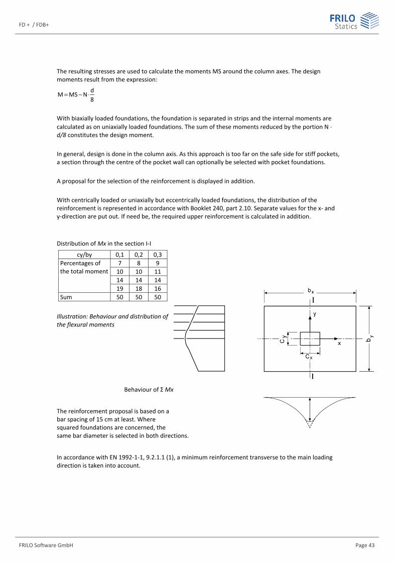
With centrically loaded or uniaxially but eccentrically loaded foundations, the distribution of the reinforcement is represented in accordance with Booklet 240, part 2.10. Separate values for the x- and y-direction are put out. If need be, the required upper reinforcement is calculated in addition.
Distribution of Mx in the section I-I
cy/by 0,1 0,2 0,3 7 8 9
10 10 11 14 14 14
Percentages of the total moment
19 18 16 Sum 50 50 50
Illustration: Behaviour and distribution of the flexural moments
Behaviour of Σ Mx
The reinforcement proposal is based on a bar spacing of 15 cm at least. Where squared foundations are concerned, the same bar diameter is selected in both directions.
In accordance with EN 1992-1-1, 9.2.1.1 (1), a minimum reinforcement transverse to the main loading direction is taken into account.
Isolated- / Block Foundation
Page 44 Software for structural calculation and design
Output: Punching shear resistance verification The following calculation results are put out for this verification:
- Diameter of the punching cone in the centre of the foundation dr and the base dk
- average existing µ in the area dr from the flexural design
- vertical force Q and decisive punching force Qred
- calculated shear stress R
- shear stress limits 1 01 compared to R and 2 02 compared to R.
If R < 1 01, shear reinforcement is not required.
If 2 02 > R > 1 01, the reinforcement ratio µ must be increased or shear additions must be installed alternatively. The software puts both values out. For the shear additions, an inclination of 45 degrees is assumed.
If R > 2 02, the reinforcement ratio µ must be increased so that the condition R < 2 02 is satisfied at least. The resulting reinforcement is put out.
Reinforcement either consisting of additional longitudinal reinforcement or shear addition must be installed in addition. Both values are put out.
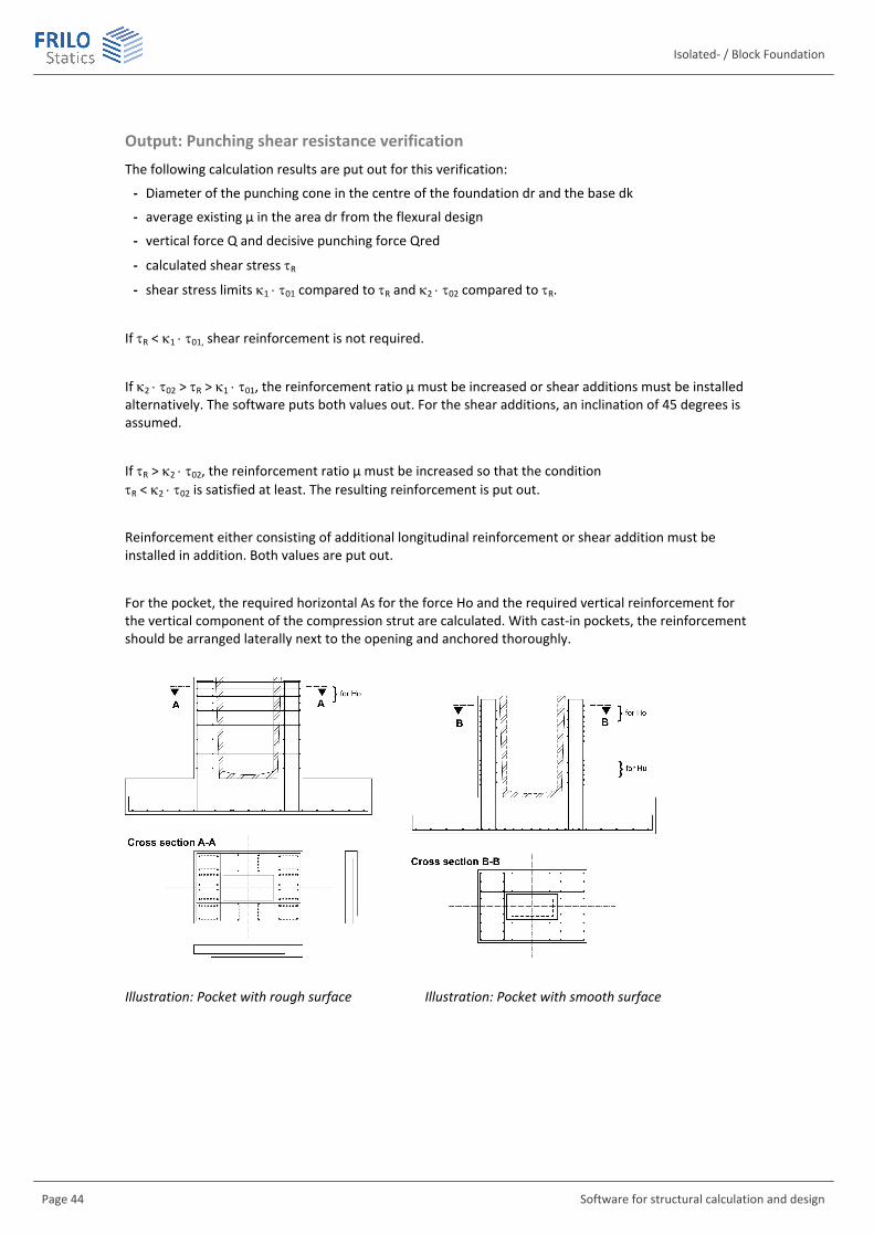
For the pocket, the required horizontal As for the force Ho and the required vertical reinforcement for the vertical component of the compression strut are calculated. With cast-in pockets, the reinforcement should be arranged laterally next to the opening and anchored thoroughly.
Illustration: Pocket with rough surface Illustration: Pocket with smooth surface