isolation, purging, and re title -introduction of gas
TRANSCRIPT

Page 1 of 44
1.0 PURPOSE AND SCOPE
1.1 The purpose of this Isolating, Purging and Re-Introduction (IPR) Gas Safety Standard Practice (SSP) is to establish minimum requirements to ensure the safety and health of employees and contractors. It shall be used in conjunction with local site/equipment specific procedures when performing purging and pneumatic blow cleaning or flammable gas commissioning activities on flammable gas piping and vessels.
1.2 This SSP applies to all contractor personnel performing IPR work. This SSP does not apply to third party owned gas systems. Contractor or third party gas provider procedures shall meet or exceed the requirements of this Standard Practice
1.3 This SSP does not apply to oxygen and liquid systems.
1.4 This SSP shall comply with the local requirements of the appropriate regulating body governing the facility or the planned activities.
1.5 The enforceable practices presented in this SSP shall include all information called out in the appendices.
2.0 REFERENCES AND PUBLICATIONS This document contains parts of the national consensus standards and codes, and other reference materials that follow.
2.2 Standard Practices It is mandatory that these and possibly other internal documents be referenced and used as they apply to the particular IPR job being completed.
2.2.1 Hot Work Standard Practice
2.2.2 Engineering Standards
2.2.3 Burning and Welding Standard Practice
2.2.4 Hot Tap Standard Practice
2.2.5 Gas Hazard Management Standard Practice
2.2.6 Energy Control Standard Practice
2.2.7 Hazardous Job Meeting (HJM) Safety Standard Practice
2.3 Codes and Regulations These national consensus codes and standards have applicability to many IPR projects and are referred to in this document.
Safety and Industrial Hygiene Safety Standard Practices
Title Isolation, Purging, and Re-Introduction of Gas Safety Standard Practices
Revision 05/01/2016 Version Number 2.0

Page 2 of 44
2.3.1 NFPA 54 National Fuel Gas Code (www.nfpa.org) Applicable to natural gas up to and including 125 psig operating pressure, propane and commercially available fuel gases.
2.3.2 NFPA 56 Fire and Explosion Prevention During Cleaning and Purging of Flammable Gas Piping Systems (www.nfpa.org) Applicable to all natural gas and flammable gas projects.
2.3.3 NFPA 2 Hydrogen Technologies Code (www.nfpa.org) Applicable only to Hydrogen systems.
2.3.4 NFPA 58 Liquefied Petroleum Gas Code, (www.nfpa.org) Applicable to LPG, (Propane), systems.
2.3.5 NFPA 70 National Electrical Code (www.nfpa.org) Applicable to electronic equipment and wiring located in hazardous areas.
2.3.6 NFPA 77 National Static Electricity (www.nfpa.org) Applicable to electrical bonding and grounding of flammable gas piping systems.
2.3.7 ASME 31.3 Process Piping Guide.(www.asme.org) Applicable to process piping systems for fuels and gasses. Similar to ASME B31.1, (Power Piping Code for boilers and steam piping).
2.3.8 Ontario Oil and Gas Pipeline Systems, O.reg 210/01 (Canadian Plants only) Applicable to systems in Ontario Canada. Many fuel system regulations at www.tssa.org
2.3.9 Federal DOT, cfr 192, PHMSA, requirements Applicable to DOT regulated systems for natural gas. In some cases on large USS sites these may apply to natural gas systems.(www.phmsa.dot.gov)
2.4 Reference Materials
2.4.1 AGA Purging Principles and Practice This is a reference document that has many valuable generally applicable processes for IPR projects. However, it is largely written for the natural gas high pressure
3.10 Contractors may fill the role of either a QPP or PET as deemed necessary by each facility and in accordance with Section 1.2 of this SSP. All contractor personnel involved in IPR activities will demonstrate levels of training and qualification that are consistent with the scope of their duties for a given project. Contractors will submit training records for employees so they can be verified through ISNET WORLD.
4.0 PROCESSES FOR CONDUCTING IPR ACTIVITIES
4.1 Facilities will use two different levels of preparation and planning for IPR activities: detailed hazardous job meeting (HJM) and hazardous job procedure (HJP) for non-routine activities and Safe Job Procedures (SJP) and pre-task plans (PTP’s) for routine activities. Planning will result in a written procedure that will be vetted through a safety validation review using the checklist provided at the end of this document. Participants in this safety validation will include individuals who have not been involved in creating the specific written procedure for the job to be safety validated. The written safety validation checklist document shall be retained for at least 2 years following the completion of the IPR activity.

Page 3 of 44
4.1.1 Routine IPR activities are those which have unchanged tasks and are performed at least once on a yearly basis.
4.1.4 All PTP activities will be completed with standardized PTP templates and guidelines.
4.2 Planning
4.2.1 The overall process for conducting safe IPR activities at facilities generally consists of the following distinct steps:
4.2.1.1 Conduct planning processes to develop an HJP or use of an existing SJP that adheres to this document’s specific requirements.
4.2.1.2 Determine method to isolate the process equipment that is involved in the work as required by this SSP.
4.2.1.3 Conduct a blow down of any pressure in the piping and/or vessel to some pressure above atmospheric pressure.
4.2.1.4 Conduct a purge of the piping or vessel so that work can safely take place.
4.2.1.5 Conduct leak checking or pressure testing as per relevant nationally applicable standards, (NFPA 54 for natural gas systems operating at 125 psig or less and ASME B31.3 for all other flammable gas piping systems).
4.2.1.6 Conduct a post repair purge after work has taken place to remove oxygen prior to introducing flammable gases.
4.2.1.7 Safely re-introduce gas to concentrations required by process start-up and operating specifications.
4.2.1.8 Conduct a post project review in the interest of continuously improving safety practices.
4.3 IPR Procedural Items The following items are to be specifically called-out in all new and existing IPR Procedures in order to comply with NFPA 56. To ensure compliance, the IPR Activity Safety Validation Checklist is used as a verification step. 4.3.1 Each plan will include a section for conducting a stand down. If the conditions during
the purging or cleaning activity deviate from those indicated in the written procedure, resulting in a safety hazard, the purging or cleaning activity shall be discontinued according to the job specific stand down procedures.
4.3.2 Conduct walk through of work site to determine the purge path, and to note any physical deficiencies during all phases of the planning process.
4.3.3 List all flammable or combustible material and have MSD sheets at planning process for review. Consider all chemical and physical properties and their impact on the jobs safety in the plan.
4.3.4 Determine if Toxic materials could be encountered when work is preformed and have MSD sheets for material in planning process for review.
4.3.5 Determine type of purge to be used (slug, dilution, trickle)

Page 4 of 44
4.3.6 Contact Utility or third party gas provider of IPR procedure and possible impact to their systems.
4.3.7 Notify Safety at the start of the IPR Process so they can be on standby with the appropriate emergency equipment and personnel.
4.3.8 Notify affected personnel of IPR procedure and all possible adverse or change conditions to their area when procedure is conducted. This will also include notification of signals for each step in the process and emergency signals.
4.3.9 Determine Fire Protection needs such as Fire Extinguishers and Type and Quantity. Fire Hoses and state such as Size, Manned, Unmanned, Dry or Pressurized.
4.3.10 All temporary piping will be designed to ASME B31.3.
4.3.11 Evacuation Signal and Emergency response plans will be detailed in the Procedure and demonstrated/reviewed with all parties involved in the procedure and in affected areas
4.3.12 Assembly/Muster areas with 2 means of egress must be established
4.4 IPR Documents and Forms The following forms are used during the IPR Process. These forms are to be attached to the job procedure, and kept at the job site. When the IPR Activity is complete, the documentation shall be kept for record keeping purposes. Samples of each form can be found in Appendix A.
4.4.1 Lockout Verification Form
4.4.1.1 All sources will be capable of being locked out. A lockout Verification form will be filled out with all isolation points identified and documented.
4.4.2 Blank and Disconnect Form
4.4.2.1 A Blank and disconnect form will be a single line drawing with all piping and directions of flows, valves, instruments in the system with all blanks and disconnects shown and identified. All blanks will be field Verified
4.4.3 Pressure Test / Leak Test Form
4.4.3.1 A Pressure Test / Leak Test form shall document sections tested, pressure held, hold time, and be signed off by a witness
4.4.4 Gas Safety Test Form
4.4.5 IPR Activity Safety Validation Checklist
4.4.6 Purge Verification Diagram
4.4.6.1 A Purge Diagram will be made as a single line diagram of the entire
system being purged. The diagram will consist at a minimum of, all piping being purged with directions of flows, all valves, purge points, vent points and instrumentation.
4.4.7 Isolation and Lockout Diagram
4.5 Management of Change Process

Page 5 of 44
4.5.1 Management of change processes exist to ensure that any changes made to procedures or needing to be made because of process changes are done with complete consideration of issues by IPR Competent Persons.
4.5.2 This process consists of a meeting or series of meetings to document the 6 items described below for a given proposed change. This shall be implemented regarding any installations or modifications that leave equipment in something other than an “as previously installed” condition or when a local procedure is modified. When these conditions occur the changes shall be documented by the Supervisor with other Managers knowledgeable of the area processes. A written record of the assessment leading to the changes shall be maintained with the completed IPR procedure.
4.5.2.1 The technical basis for the proposed change
4.5.2.2 The safety and health implications
4.5.2.3 Whether the change is permanent or temporary
4.5.2.4 Modifications to cleaning and purging procedures
4.5.2.5 Employee training requirements
4.5.2.6 Authorization requirements for the proposed change
5.0 ISOLATION OF PROCESS EQUIPMENT AND PIPING
5.1 The steps for isolating process systems and equipment are accomplished by using a combination of:
5.1.1 Safe Job Procedures
5.1.2 Energy Control Procedures
5.1.3 Hazardous Job Procedures
5.2 Devices and Methods of Isolation
5.2.1 Isolations can be positive or non-positive depending on the circumstances and equipment at hand. Isolations must be consistent with the procedure requirements and must stay this way throughout the procedure. Positive isolations shall be considered “leak-free”. Non-positive isolations shall not be considered “leak-free”.
5.2.2 Positive isolations are required for the following:
5.2.2.1 Confined space entry
5.2.2.2 Areas where the accumulation of combustible gases is possible (i.e. open pipe segments or systems inside buildings and or poorly ventilated areas).
5.2.2.3 Areas where open pipe segments within 35 feet to oxidizing materials (e.g. oxygen or chlorine piping and storage equipment).
5.2.3 The following shall be considered positive isolation devices and methods.
5.2.3.1 Slip blank
5.2.3.2 Blind flange
Page 6 of 44
5.2.3.3 Goggle valve
5.2.3.4 Disconnect and cap or plug
5.2.3.5 Double-block and bleed (with specific requirements)
5.2.3.5.1 Double-block and bleed is only considered positive isolation after proving acceptable and sustainable conditions between both block valves.
5.2.3.5.2 If at any time the gas test results indicate unacceptable atmospheric conditions (>10% LEL) and /or pressure buildup between the double-block and bleed, it will be reclassified as a non-positive isolation method as defined in section 5.2.5.
5.2.4 The following shall be considered non-positive isolation devices. These devices can be used for the purposes of installing a positive isolation device, so long as a satisfactory endpoint test has been achieved:
5.2.4.1 Plug valve (lubricated)
5.2.4.2 Ball valve
5.2.4.3 Stopple
5.2.4.4 Inflated bag
5.2.4.5 Cryogenic Freeze plug
5.2.4.6 Single Gate valve
5.2.4.7 Butterfly valve
5.2.4.8 Globe valve
5.2.4.9 Double disc gate valve
5.2.5 Non-positive isolation methods are preferred over non-positive isolation devices. The following shall be considered non-positive isolation methods, in order of preference (see Appendix C):
5.2.5.1 Water or Nitrogen sealable Double-disc Gate Valve
5.2.5.2 Double-block and pressurize
5.2.5.3 Water seal leg
5.2.5.4 Double-block and bleed (if specific requirements listed in 5.2.3.5 are not met)
5.2.6 Non-positive isolation methods, that are monitored at a frequency determined in the SJP or HJP for effectiveness, can be used when acceptable endpoint results are achieved to perform the following:
5.2.6.1 Cold Work – breathing air and PPE requirements to be determined during the IPR Planning meeting
5.2.6.2 On a temporary basis for installing a positive isolation device – see 7.2 for breathing air and PPE requirements.
5.3 Common Isolation Valve Issues
Page 7 of 44
The following are common isolation valve issues. These need to be considered and planned for when considering isolation method options.
5.3.1 Valve Seat Deposits
5.3.2 Valve Seat and Disc Degradation
5.3.3 Stem and Bushing Failure
5.3.4 Plug Valve Lubrication
5.4 Techniques to Address Isolation Valve Issues
5.4.1 Utilize clean out ports located on valve seating (For seat deposits)
5.4.1.1 Steam
5.4.1.2 High-pressure water wash (with packing gland)
5.4.1.3 Chemical injection
5.4.2 Steam trace valve body (For seat deposits)
5.4.3 Lubrication of valve components (For most valve types)
5.4.4 Rebuild or replacement of valve components (For all valve types)
6.0 PURGING
6.1 Purge mediums such as an inert gas, steam, or water are utilized to replace the contents of the vessel or piping. The replacement of one medium by another (purging) in process piping and equipment shall take place by displacement, dilution (mixing), or a combination of both.
6.2 In the case of introducing a purge medium at the extreme end of a pipeline, and venting it out the other end (sweep or slug purge), the purge path would be the length of pipe. Often complex piping, vessels, and branch lines have to be included in the purge path. Careful consideration must be given to all connecting paths in the process piping and equipment to be sure that all are thoroughly purged; including low spots, high spots, areas of changing cross-sectional diameter, and places where liquids could have accumulated. Plans need to include considerations for dead end sections or pockets of product that might remain un-purged.
6.3 Purging operations that introduce an inert gas shall be continuous until the flammable gas concentration detected at the discharge end of the permanent piping system or in the vent line is such that the inert gas-flammable gas mixture is not ignitable when released in air.
6.4 Purge out of Service
6.4.1 The objective of purging out of service is to remove flammable and toxic materials from piping systems to make them safe to open and perform work.
6.5 Purge into Service
6.5.1 The objective of purging into service is to remove air/Oxygen from piping systems and then to re-introduce gas in concentrations suitable for the process.
6.6 Purging Techniques (refer to Appendix E)
6.6.1 Displacement Purging (slug)

Page 8 of 44
6.6.2 Dilution Purging
6.6.3 Trickle Purging
6.7 Venting and de-pressurizing considerations
6.7.1 Combust flammable gases through existing flare systems or operating systems where possible. It is better to consume excess pressure in a system in some useful safe and closed system rather than to discharge it.
6.7.2 Vent discharges shall terminate outdoors.
6.7.3 The vent line from a piping system being purged shall be equipped with a readily-accessible or remotely actuated shut-off valve.
6.7.4 Vent points shall be accessible for test purposes and control of purge medium flow.
6.7.5 Discharge locations shall consider the volume of purged materials, its velocity, and specific gravity to define distances to building openings and or barricade areas and possible sources of ignition (35 feet minimum).
6.7.6 Consideration shall be given to wind direction, traffic, and personnel exposure when locating vents.
6.7.7 Effects of weather shall be considered for venting. Overcast, foggy, rainy, or atmospheric inversion conditions will tend to make vented gases hang near the ground, even if lighter than air.
6.7.8 Venting coke oven gas or other benzene-bearing products is regulated. See Customer Plant Policies for reporting requirements.
6.7.9 Hydrogen venting has a wide flammable range (4% - 75%), and high flame speed (9.3 feet per second). Pipelines and vessels in hydrogen service that are not designed for routine process discharge and are being purged for maintenance shall be vented through a flame arrestor designed for hydrogen gas.
6.7.10 Consideration will be given to the discharging of static electricity and possible grounding needs at vent points to prevent possible ignition source. All Bonding/Grounding Circuits will be designed in conformance with NFPA70. When confirming a Bonding /Grounding system a continuous ground path will be less than 10 Ohms of resistance. This will be checked and verified with the use of an Ohm meter between all connections in the Bonding/Grounding circuit prior to any work being performed
6.8 Air Monitoring (Exclusion Zone) Considerations
6.8.1 Air monitoring for the build-up of flammable gas concentrations (LEL) or toxic concentrations near and around the purge vent (exclusion zone), shall be performed while purging and returning process equipment and piping to service.
6.8.2 Consideration for air monitoring for flammable gas concentrations (LEL) or toxic concentrations shall include buildings near vent points and near where new and repaired valves, flanges, blanks, piping repair patches that may exist, and any other areas identified during the hazard analysis.
6.9 General Purge Endpoints

Page 9 of 44
6.9.1 Atmosphere testing is necessary to ensure that the purge has been successful in creating the desired removal of flammable gases from the equipment involved. Atmosphere testing is also necessary to purge equipment back into service. In all cases, the object is to assure that the specified replacement product has reached its desired concentration, proved by an accurate test of the product’s key characteristic(s), by a PET.
6.9.2 There are usually three (3) endpoint tests for a purge job involving flammable and toxic product systems.
6.9.2.1 Purge out of Service (1) - Purging out oxygen (air), flammables and toxics.
6.9.2.2 Purge into Service (2 and 3) - Purging oxygen (air) out of system if opened to atmosphere, re-introducing flammables into system.
6.9.3 Endpoints shall be monitored on a continual basis with equipment and techniques that do not expose endpoint testers to hazards. Monitors used shall be reviewed to be capable of proper operation with sample hose lengths that may be required.
6.9.4 The standard for endpoint testing for purging out a pipeline or vessel of flammable and toxic products shall meet all requirements below:
6.9.4.1 Less than 10% of the lower explosive limit (<10% LEL) of the gas or vapor in question
6.9.4.2 Less than 5% Oxygen
6.9.4.3 Less than 1% Oxygen for Hydrogen Systems
6.9.4.4 Toxicity tests to determine PPE requirements.
6.9.5 Endpoint test results for purging back into service (if required), of a flammable product, shall be continuous until at least 90% flammable gas by volume or the minimum concentration established by the HJP or SJP is detected at the discharge end of the piping system or in the vent line.
6.10 Measurement Devices and Techniques
6.10.1 Electronic Devices – Approved for use
6.11 Lab analysis for steam purging (refer to Appendix F)
6.12 Factors Affecting Purging Efficiency and Operations
6.12.1 Two factors shall be considered that affect dilution are the “time of contact” and the “area of contact”. The longer the time or area of contact between the inert gas and the surface of the original contents, the greater the chance for natural diffusion causing dilution.
6.12.2 Efficient purging is affected by the relative vapor densities of the gases.
6.12.3 Efficiency may be improved by:
6.12.3.1 Introducing the heavier purge medium at the base of the chamber to lift the lighter contents through vents at the top of the chamber.
6.12.3.2 Introducing the light gas at the top of the chamber and venting the heavier purge gas at the bottom.

Page 10 of 44
6.12.3.3 Temperature differentials will increase the mixing between the purge medium and contents being purged.
6.12.3.4 Positive pressure shall be maintained during purging to prevent air infiltration into the vessel or piping. Air infiltration may create an explosive atmosphere.
6.13 Purge Medium Pressure and Equipment Damage Hazards
6.13.1 The purge medium supplier shall be required to provide a product review and MSDS.
6.13.2 Purge medium sources may be at pressures that are far beyond the rating of piping systems or vessels being purged. Purging may cause increased pressure(s) resulting in damage to process equipment. Regulators must be carefully adjusted and pressures carefully monitored with gauges to ensure the protection of all process equipment and hoses involved in the purge. All piping including hoses must be designed and install per ASME B31.3.
6.13.3 The maximum purge pressure shall be established in the IPR Procedure and corresponding IPR Activity Safety Validation Checklist.
6.13.4 Pressure gauges shall be monitored by an assigned individual in communication with the PPC until the process equipment has been safely purged.
6.13.5 If the purge medium source is capable of delivering more pressure than the process is rated, a manifold with properly sized pressure relief and gauging shall be required in addition to gauging on the pipe or vessel being purged.
6.13.6 When using high-pressure cylinders such as nitrogen, a cylinder gauge shall be used.
6.13.7 Procedures shall detail use of cryogenic equipment and required PPE and the contractor shall comply with all Customer’s rules and regulations.
6.13.8 When using a cryogenic purge medium, such as liquid nitrogen, all equipment including gauges, hoses, and manifolds shall conform to the manufacturer’s specifications for the cryogenic material being used. PPE requirements shall also be adjusted accordingly. 6.13.9 The cryogenic purge medium shall be vaporized before being introduced to the process equipment or piping.
Caution: It is critical NOT to introduce cryogenic liquid into the pipe or vessel being purged. Carbon steel piping systems in particular can suffer catastrophic brittle fracture failure when exposed to cryogenic liquid operating temperatures.
6.14 Purging System Related Valves and Piping
6.14.1 All purge valves and related piping shall conform to engineering design specifications. Any deviations shall be approved by the facility engineering organization.
6.15 Purge Medium Considerations
6.15.1 General
6.15.1.1 For locations that have storage and purge media onsite, before purging can be performed, it shall be determined that sufficient supply exists for simultaneous purging; facilities operations and emergency uses.

Page 11 of 44
6.15.1.2 All hoses and piping shall be protected from physical damage from mobile or other equipment by using protective covers, flagging, or barricades. All hoses shall be rated appropriately.
6.15.1.3 Portable inert gas trailers and trucks shall be placed in an approved location and comply with plant specific rules and regulations including considerations for wheel chocks.
6.15.1.4 Portable inert sources shall be sized accordingly to ensure safe displacement of the system’s original contents.
6.15.1.5 Purging shall be accomplished by using inert gases or alternative purge medium to safely displace the contents of a vessel or piping.
6.15.1.6 Examples of purge media commonly used are:
6.15.1.6.1 Nitrogen 6.15.1.6.2 Argon 6.15.1.6.3 Steam 6.15.1.6.4 Water
See Appendix E for more information regarding uses of common purge media
7.0 BLANKING
7.1 Blanking Installation and Removal
7.1.1 The typical sequence of blank installation is as follows:
7.1.1.1 Bolt rehearsal as required. (Appendix D)
7.1.1.2 Determination of conditions inside of the pipe that to which the workers will be exposed upon opening of the joint, and the resultant sweep or purge plan
7.1.1.3 Determination of precautions to be taken to protect the workers such as local ventilation, bonding, breathing air, PPE, special tools, ignition sources, and fire protection.
7.1.1.4 Determination of the appropriate sized blank and gasket(s) to be used
7.1.1.5 Flange unbolting and bolting, with emphasis on keeping control of the joint.
7.1.1.6 Inspect flange faces, and clean to remove any materials that will impact sealing surfaces
7.2 Requirements for Installing and Removing Blanks For the purposes of positive isolation from all upstream and downstream gas sources
7.2.1 Breathing Air
7.2.2 Fire Retardant Clothing to minimize exposed skin (snoods, gloves)
7.2.3 System locked out and Depressurized
7.2.4 Purge established

Page 12 of 44
7.2.5 Endpoint test completed – test at reduced positive purge pressure, 2 inches of water column (wc) or less for a sustained amount of time at pre-determined size and number of vents, representative of the system being tested.
7.2.5.1 % Oxygen – must be less than 5%.
7.2.5.2 % Oxygen – must be less than or equal to 1% for Hydrogen Systems
7.2.5.3 % of the LEL – must be less than 10% (Installing Blanks).
7.2.6 For non-positive isolation jobs: assess gas leakage, maximum allowable leakage to be determined
7.2.6.1 Performing gas leakage calculations and how to interpret results and determine maximum allowable leakage shall require separate training, beyond the scope of this document.
7.2.7 Assess for ventilation needs where accumulation of combustible, toxic and inert gases is possible and use if needed.
7.2.8 Once Blank has been installed, any residual concentrations of gas shall be purged from the pipe to acceptable endpoint levels for safe work
7.2.9 A system leak test is required prior to removing blank(s). See section 8.1.
Note: When removing a blank from an isolation valve, expect an initial short-duration outflow of any small volume of gas that may be pressurized inside the valve between the gate and the blank at the instant that the gasket seal is broken
7.3 Tool Requirements For the purposes of positive isolation from all upstream and downstream gas sources
7.3.1 Electrical bonding/grounding cables are required. All Bonding/Grounding Circuits will be designed in conformance with NFPA70. When confirming a Bonding /Grounding system a continuous ground path will be less than 10 Ohms of resistance. This will be checked and verified with the use of an Ohm meter between all connections in the Bonding/Grounding circuit prior to any work being performed.
7.3.2 Steel wrenches are permitted (not to be used as striking tools)
7.3.3 Striking tools must be non-sparking
7.3.4 No electric tools when joint is compromised
7.3.5 Pneumatic tools and hydraulic bolt torque tools that are non-sparking are permitted when joint is compromised.
7.4 Ignition Sources
7.4.1 Consider all possible ignition sources (non-intrinsically safe, incendiary, non-explosion proof electrical and electronic devices, static electricity and mobile equipment).
7.4.2 Consideration to prevent gas accumulations within 35 feet of the open joint, or as determined during an IPR review meeting or HJM.
7.4.3 Minimize ignition sources within a minimum of 35 feet of the open joint, or as determined during an IPR review meeting or HJM.
Page 13 of 44
7.5 Blanks and Gaskets
7.5.1 Minimum blank thicknesses shall be determined by ASME B31.3 using the maximum process pressure and temperature. (Refer to IPR website for the Formula / Calculator for Blank Thickness).
7.5.2 A program for identifying blanks, spacers, screens and orifices shall be in place at each facility. This shall include external markings so they can be identified if installed.
7.5.3 Gaskets shall be installed on both sides of the blank wherever possible.
7.5.3.1 When only one gasket can be used, it shall be installed on the “process” side. Construction or BHLH (Big Hole/Little Hole) Blanks only require a gasket on the “process” side.
7.5.3.2 On Vacuum Systems, the “vacuum” side is the “process” side.
7.5.3.3 Gaskets are not to be re-used, see Appendix D.
7.6 Personnel & Area Restrictions
7.6.1 Only authorized personnel are permitted in the area during the blanking and blank removal process.
7.6.2 A restricted area (exclusion zone) shall be established based on purge volume, weather conditions, and the location of the job, and shall be a minimum of 35 feet from any open joints.
7.7 Special Considerations for Purging while Blanking
7.7.1 Once the purge is established at the prescribed vent pressure, it shall not be adjusted to compensate for fluctuations due to flange opening, unless specifically called out in the IPR procedure (Not including vacuum systems). Upon opening of flanges, the vent pressure may appear to drop to zero. As long as the purge supply is energized, the vent pressure will actually remain positive, but not measurable as such.
8.0 RE-INTRODUCTION AND PROCESS START-UP
8.1 Pressure and Leak Testing
8.1.1 Prior to blank removal, specific steps for pressure and leak testing and returning to service shall be defined in the IPR procedure. Pressure and Leak testing and inspection shall be documented
8.1.1.1 For existing systems, at a minimum, leak testing using a nonflammable purge media shall be performed on all disturbed flanges tested to system pressure using a recognized method (soap or leak detection fluid test with nitrogen, hydrostatic testing, and portable leak detectors). Tighten where required. Test pressure not to exceed the rating of associated instrumentation and relief valves connected to the system.
8.1.1.2 Pneumatic pressure or leak checking shall include considerations for hazards associated with the energy stored and the pressures required. Pneumatic testing of systems operating over 125 psig shall include verification of

Page 14 of 44
mechanical integrity of the piping systems and reconsideration of the exclusion zone and personnel in the areas.
8.1.1.3 Pressure testing, is required to be held for at least 10 minutes and as long as is required to completely examine the piping system. All joints and connections shall be visually inspected for leakage.
8.1.1.4 Pressure testing, shall be in accordance with ASME B31.3 for new systems unless they are natural gas systems operated at less than 125 psig. Natural gas systems operated at less than 125 psig shall be pressure tested in accordance with NFPA 54, (the national fuel gas code).
8.1.1.5 There are two acceptable testing methods for pressure testing (hydrostatic testing and pneumatic testing) identified in ASME B31.3.
8.1.1.5.1 Hydrostatic test, is generally the preferred alternative,
because it is conducted at a higher pressure, which has beneficial effect, and is substantially less risk than a pneumatic test. The test shall be conducted at a pressure of 1.5 times the design pressure.
8.1.1.5.2 Pneumatic test is considered to potentially entail a significant hazard due to the amount of stored energy in the compressed gas. Because of this concern, the pneumatic test pressure is specified to be at 1.5 times the design pressure for Natural Gas <125psi and 1.1 times the design pressure for all other flammable gas and Natural gas >125psi, but not to exceed 1.33 times the design pressure
8.1.1.5.3 Pneumatic test requires an intermediate hold at the lesser of one-half of the test pressure or 170 kPa (25psi) with a visual inspection of all joints is required prior to bringing the pressure gradually up to the full test pressure.
8.1.1.5.4 Caution must be utilized when using nitrogen or any inert gas for pneumatic pressure testing in an enclosed area, or
building. Compressed air may be required during the initial pressure test of a new system to prevent an asphyxiation hazard and the buildup of inert gas from lose connections (see section 9.4)
8.1.2 Post blank removal, specific steps for leak testing and returning to service shall be defined in the IPR procedure
8.1.2.1 Blanking flanges shall be pressure tested to system pressure using a recognized method (soap or leak detection fluid test with nitrogen, hydrostatic testing, and portable leak detectors). Tighten where required.
8.2 Requirements for Re-introduction
8.2.1 Pressure test and / or leak check shall be completed and documented prior to reintroduction of gas. Pressure test shall be in accordance with nationally applicable codes or standards. Piping system verified to be in good working order (no leaks).
8.2.2 System locked out and Depressurized
Page 15 of 44
8.2.3 Complete pre-blank removal purge
8.2.4 Endpoint test completed – test at reduced positive purge pressure, 2 in w.c. or less, representative of the system being tested.
8.2.4.1 % Oxygen – must be less than 5%.
8.2.4.2 % Oxygen – must be less than or equal to 1% for Hydrogen Systems
8.2.5 Blanks removed
8.2.6 Complete post-blank removal pressure test and / or leak check, verify no leaks and document results
8.2.7 Complete post-blank removal purge
8.2.8 Endpoint test completed – test at reduced positive purge pressure, 2 in w.c. or less, representative of the system being tested.
8.2.8.1 % Oxygen – must be less than 5%.
8.2.8.2 % Oxygen – must be less than or equal to 1% for Hydrogen Systems
8.2.9 Unlock system to re-introduce gas
8.2.10 Endpoint test completed when required by the SJP or HJP.
8.2.10.1 % Flammable gas – 90% by volume or greater (or as specified in the HJP or SJP)
8.2.11 System now available to customer personnel
9.0 SPECIAL HAZARDS
9.1 Pyrophoric Materials
9.1.1 Pyrophoric substances ignite readily upon exposure to air (atmospheric oxygen). The coke making process generates gases that produce pyrophoric compounds. These compounds are found throughout the by-product recovery system where coke oven gas, cooling liquors and by-products have come in contact with process equipment. The hydrogen sulfide found in coke oven gas reacts with iron, forming iron sulfide compounds that oxidize rapidly when exposed to air. The oxidation reaction generates enough heat to be a source of ignition for any gases, oils, tars, and residues commonly coating the interior walls of process equipment.
9.1.2 Precautions shall be taken to prevent ignition of these compounds when exposing process equipment to air.
9.1.2.1 Trickle purging with nitrogen or argon to keep oxygen out of the system will prevent ignition of these compounds.
9.1.2.2 Any vessel or piping system opening should be sealed immediately when possible.
9.1.2.3 Water, steam and or chemical neutralization agents can be used to prevent the ignition of these compounds
9.1.2.4 A fire hose shall be present at the work site when process vessels or piping systems are opened.

Page 16 of 44
9.1.3 Since these compounds will have the potential to ignite once they dry out. Wet pyrophoric material shall be promptly removed to an area where its subsequent ignition and burning will cause no damage.
9.2 Coke Oven Gas Condensate
9.2.1 Coke oven gas leaving the gas cleaning process is saturated with water vapor and contains hydrocarbon vapors not captured by the process. The gas cools as it is sent through piping to the end users resulting in condensation of liquid water and liquid hydrocarbons such as benzene, toluene, and xylene. The condensed hydrocarbons are highly flammable and toxic. Since the liquid hydrocarbons are only slightly soluble in water, flammable liquids may accumulate in condensate drain piping and dead legs.
9.2.2 IPR procedures for processes containing coke oven gas shall address the hazards associated with coke oven gas condensate.
9.3 Gas Main Deposits
9.3.1 Coke oven gas mains and vessels contain deposits of solids such as tar and naphthalene that remain after the draining of condensates is complete. Hot work may liquefy and volatilize these deposits producing flammable liquids and vapors which may ignite or explode.
9.3.2 Potentially flammable deposits shall be steamed out, physically removed, or rendered non-combustible by reducing the Oxygen content with Nitrogen or other suitable media.
9.4 Nitrogen and Argon Hazards
9.4.1 Nitrogen and argon can pose an asphyxiation hazard by creating an oxygen deficiency in the worker’s breathing zone. This hazard can be minimized through safe work practices and training.
9.4.2 All individuals involved in the use of nitrogen and argon shall be trained as to the hazards associated with their use.
9.4.3 Areas where the following PPE are required shall be stated during the IPR review meeting, as per the Gas Hazard Management Program.
9.4.3.1 Self-contained breathing apparatus
9.4.3.2 Monitors measuring oxygen deficiency
9.5 Precautions for Systems Under Vacuum Air infiltration into combustible gas processes under vacuum during IPR processes present special risks that cannot be over emphasized. The potential for an incident is significantly increased if proper safe guards are not in place. This section attempts to provide information to the reader to reduce risks for vacuum related gas IPR jobs. The specific vacuum related system issues listed below shall be considered, and reviewed during the IPR review meeting or HJM process.
9.5.1 Flammable or Explosive Mixture Determination: A determination of all process stream characteristics must be evaluated and included in the detailed IPR plan. Composition of the gas, system pressures, system temperature, process flow rate, estimation of air infiltration rate at the known ΔP, LEL and UEL levels depending on gas composition,

Page 17 of 44
etc. All possible air infiltration points, (including the opening of flanges), shall be identified and discussed prior to the IPR job taking place to prepare for the possibility of air coming into contact with combustible gases or pyrophoric substances when process vessels and piping are under vacuum.
9.5.2 Sample Ports and Sampling Techniques: Determine proper gas monitoring techniques and sampling locations considering that the system is under vacuum and not pressure. Minimize vacuum pressure of system before attempting to monitor or sample gas streams. See Appendix F.
9.5.3 Minimizing Process & Operational Changes: Consider minimizing operational & process changes during IPR processes under vacuum. (for example, stop pushing and charging, turn off aspirating steam, etc.) so that conditions are and remain as stable as possible. Downstream processes that have a strong potential to be a source of ignition, i.e. tar precipitators, should be powered down and be made part of the job lock out procedure.
9.5.4 Nitrogen or Steam to Dilute Infiltrated Air: Nitrogen and/or steam injection locations should be established as close to the blank site as possible to minimize air infiltration. It is preferable that Nitrogen or steam be able to enter openings under vacuum and not air.
9.5.5 Vacuum Measurement: An accurate vacuum-type pressure gauge or manometer shall be installed in order to monitor the pressure and vacuum conditions at all times during the IPR process.
9.5.6 Dedicated Person for Monitoring Gas Conditions: An IPR competent person shall be identified with the sole responsibility of monitoring process parameters for the system under vacuum in order to identify changed conditions during the isolation, purging, and re-introduction processes that would cause a condition to reach the LEL or UEL limits.
9.5.7 Minimizing Air Infiltration to Flanges & Bolt Holes: Whenever flanges are separated where a system is under vacuum install a half band around the bottom of the flange to serve as temporary blockage to minimize air infiltration (leakage) to the system. (Belting, wood, gasket material, etc.) Materials to cover bolt holes shall be available for use once bolts have been removed from the flange.
9.5.8 Special Emergency Planning: Establish a worst case scenario plan and appropriate actions to be taken if the system vacuum is lost. Determine how to control the hazard and what safeguards can be put in place to minimize exposure to employees or equipment.
9.5.9 Coke Facility Gooseneck Special Precautions: When performing valve body, inside riser, or gooseneck work on collector mains a near zero pressure/vacuum condition is to be maintained. (+1 mm w.c. to -1 mm w.c.)

Page 18 of 44
APPENDIX A – Explanatory Materials
A.1 Definitions Table A1 - Purging and Blanking Definitions
Term Definition
Air A gas surrounding the earth that contains about 78% nitrogen, 21% oxygen, and the balance, water vapor, argon, carbon dioxide, et al. Its vapor density equals 1.0.
Asphyxiant A gas or vapor which can cause suffocation from lack of oxygen.
Auto-Ignition Temperature The lowest temperature at which a flammable gas or vapor/air mix will ignite without an ignition source. Increased oxygen or catalysts will reduce this temperature.
Blanking See Slip Blank
Blind Flange A positive means of isolation, whereby a flange is used to close off and secure the open end of a pipe.
Boiling Point
The temperature of a liquid at which its vapor pressure is equal to or very slightly greater than the environment’s atmospheric pressure. The temperature at which a liquid changes to a vapor state, at a given pressure.
Bonding
The interconnecting of two objects by means of a clamp and bare wire. Its purpose is to equalize the electrical potential between objects. (See Grounding). All Bonding/Grounding Circuits will be designed in conformance with NFPA70. When confirming a Bonding /Grounding system a continuous ground path will be less than 10 Ohms of resistance. This will be checked and verified with the use of an Ohm meter between all connections in the Bonding/Grounding circuit prior to any work being performed.
Catalyst Any substance that changes the speed of a chemical reaction but undergoes no permanent change itself.
Cold Work Maintenance activity which is not likely to create an ignition source (e.g. wrench work, water blasting).
Term Definition

Page 19 of 44
Competent Person, also, IPR Competent Person
A person who by virtue of their training and or experience is capable of identifying existing and predictable hazards in the surroundings or working conditions which are unsanitary, hazardous, or dangerous to employees, and who has authorization to take prompt and corrective measures to eliminate them. (OSHA definition, 29cfr 1926.32(f))
By way of training and/or experience, a competent person is knowledgeable of applicable standards, is capable of identifying workplace hazards relating to the specific operation, and has the authority to correct them. Some standards add additional specific requirements which must be met by the competent person
Construction Blank
A specially designed slip blank that can be secured both between two flanges with large bolts or only on one flange with small bolts. A construction blank is commonly called a “big hole, little hole” blank (BHLH).
Cryogenic
Liquefied gases, such as liquid nitrogen and liquid helium, are used in many cryogenic (low temperature) applications. Liquid nitrogen is the most commonly used element in cryogenics and is typically at a temperature of less than -200°F.
Endpoint
Attainment of a concentration (percent by volume) of an inert substance in the closed system being purged such that the subsequent admission of air (if purging out of service) or the admission of gas or vapor (if purging into service) will not result in formation of a flammable mixture.
Explosion Proof
Apparatus enclosed in a case that is capable of withstanding an explosion of a specified gas or vapor that may occur within it and of preventing the ignition of a specified gas or vapor surrounding the enclosure by sparks, flashes, or explosion of the gas or vapor within, and that operates at such an external temperature that a surrounding flammable atmosphere will not be ignited thereby.
Term Definition
Explosive Limits
(LEL and UEL)
The explosive limit of a gas or a vapor is the limiting concentration (in air) that is needed for the gas to ignite and explode.
At concentrations in air below the lower explosive limit (LEL) there is not enough fuel to continue an explosion; at concentrations above the upper explosive limit (UEL) the fuel has displaced so much air that there is not enough oxygen to begin a reaction.
Concentrations of explosive gases are often given in terms of percentages of gas in air or in percent of lower explosive limit (%LEL).

Page 20 of 44
Flammable Range Concentrations of a flammable gas between the lower explosive limit (LEL) and the upper explosive limit (UEL).
Flashpoint The lowest temperature at which a liquid gives off enough vapor to form an ignitable mixture with air and produce a flame when an ignition source is present.
Gas
A state of matter without shape or defined volume. Gases are of low density, diffuse easily, and contract and expand greatly with changes in temperature.
Gases found include, but are not limited to: acetylene, natural gas (methane), coke oven gas, blast furnace gas, basic oxygen furnace gas, propane, oxygen, nitrogen, argon, hydrogen, carbon dioxide, vaporous components of alcohol, gasoline, light oils and fuel oils and compressed air lines.
Gas Mains The piping between the product source area (where gas is produced) and the first valve inside any downstream building or other process area.
Gas Testing The act of sampling atmospheric conditions for toxic gases, explosive level, and oxygen content using gas testing instruments and sampling equipment.
Goggle Valve
A positive isolation device, consisting of two components, a solid disc and an expansion joint. The valve operation requires that the flange faces be separated by thermo-mechanical or hydraulic means, to allow for the solid disc to be inserted into the gas stream, either manually or by a small electric motor. Once the solid disc has been installed into the gas stream, the separation means is reversed, which in turn seals up the flange faces.
Term Definition
Grounding The procedure used to carry an electrical charge to ground through a conductive path. (See Bonding).
Hot Tap
The process by which a valve is attached to a pipe while it is in service through a special process conducted by a qualified contractor.
Consists of welding a valve mounting to a pipe, then with a specially sealed drilling device, drilling an opening in the pipe through the newly installed valve, retracting the drill and closing the valve, without releasing product to atmosphere.

Page 21 of 44
Hot Work
Any activity which has the potential to produce enough heat to cause ignition of a combustible material. Examples are: burning, welding, airarcing, soldering, and rotary-sawing, grinding, sandblasting, and the use of electrical equipment not rated for use in gas hazard areas.
Ignitable Mixture A mixture of a gas with air between the ranges of flammability that can propagate a flame away from a source of ignition.
Intrinsically Safe System
Intrinsically safe is a practice where one is restricting the energy available to electrical equipment in a potentially hazardous area so that a spark or hot surface can not occur due to any type of electrical fault. The IEC states that “Equipment must not store or generate more than 1.2 V, 0.1 a, 20 microjoules, and 25 mW”.
IPR Activity Safety Validation Checklist
An itemized list developed to remove questions and/or oversight during purging activities; used in the field and at meetings.
Inert Medium
A material or substance that does not have any active properties relative to the materials surrounding it, used for purging.
Nitrogen (and sometimes carbon dioxide) are commonly used to purge flammable gases, but would not be appropriate for certain product purges, such as burning magnesium, since they are not truly inert. (e.g., nitrogen compounds are common.) Gases such as argon, helium, and neon are truly inert gases, as there are no known compounds containing them.
Inert Purge The act of changing the contents of a pipe or container by using an inert substance to displace the original content or to separate the two media being interchanged. Flammable mixtures are thus avoided.
Term Definition
Inflatable Bag A bag inserted into a pipeline through a hole in the pipe, then inflated with an approved medium to effect a seal.
Isolation Disconnection and sealing off the flow path from all other equipment or piping of a chamber or space to be purged.
Non-Incendiary Device A protection technique for safe operation of electronic equipment under normal operating conditions.
Oxygen Deficiency
The concentration of oxygen by volume below which atmosphere supplying respiratory equipment shall be provided. It exists in atmospheres where the percentage of oxygen by volume is less than 19.5%.

Page 22 of 44
Packing Gland
The packed gland is used primarily for sealing process valve shafts (axial movement) and for process pump shafts (rotary movement); for the purposes of purging it can be used to provide a seal when cleaning gas valve seats.
Relative Density The ratio of the density (mass of a unit volume) of a substance to the density of a given reference material (Dry Air).
Slip Blank A properly fabricated and engineered blank inserted between two flanges in order to achieve a positive isolation downstream.
Specific Gravity Relative density with respect to air.
Static Electricity
If two objects are close physical contact and then separated, the objects sometimes collect an electrical charge through friction or induction. Similar electric charges can be generated by rapid flow of gases or liquids. If the objects are not bonded or grounded, they may accumulate sufficient electrical charges so that an electrostatic (spark) discharge between them may occur.
Stopple A device that is inserted into a pipeline to stop the flow of product, often used as a non-positive isolation. It is usually inserted using hot tap methods.
Time Weighted Average A time-weighted average airborne concentration of a biological or chemical agent to which a worker may be exposed in a work day or work week.
Trickle Purge A very low flow purge used to maintain a purge, or to conduct a purge test. It is described as a “breath” of flow.
Term Definition
Vapor Pressure The pressure exerted by a saturated vapor above its own liquid in a closed container. Vapor pressure is usually measured in millimeters of mercury (mm Hg) or atmospheres (atm).
Vessel Any pipe or container.

Page 23 of 44
APPENDIX B – Common Gas and Product Properties Table B1 – Common Gas and Product Properties
Flammables (Approximate Values)
Product Relative Density Flammable Range Contents (see legend)
Blast Furnace Gas 1.02 35% – 65% CO, CO2, N2,H2
Coke Oven Gas 0.40 4.5% – 35% CH4, H2, CO, C2H4, BTX
Natural Gas 0.68 5.0% – 13.5% CH4
Propane Gas 1.56 2.2% – 9.5% C3H8
“Light Oil” Vapor 2.7 1.3% – 7.1% BTX (~45–70% benzene)
“HNX” Gas 0.96 72% – 75.5% 6% H2, 94% N2
“HNX” Gas 0.96 28% – 76% 15% H2, 85% N2
Kerosene Vapor 4.50 1.2% – 6% HC w/flashpoint >100°F
Gasoline Vapor 3.50 1.4% – 7.6% HC w/flashpoint ~ –50°F
Naphthalene Vapor 4.42 0.9% – 5.9% C10H8
Air (dry) 1.0 none 78% N2, 21% O2, et al.
Anhydrous Ammonia 0.596 16% – 25% NH3
Hydrogen 0.07 4% – 75% H2
Acid Gas 1.35 4.3% – 46% CO2, N2, H2S, HCN
Legend
CO – carbon monoxide, CO2 – carbon dioxide, CH4 – methane, C2H4 – Ethylene, H2 – Hydrogen, N2 – Nitrogen, O2 – oxygen, BTX – benzene/toluene/xylene, HC – hydrocarbon, HNX – hydrogen and nitrogen mixture (protective or atmospheric gas)

Page 24 of 44
APPENDIX C: Methods of Isolation
C.1 Double-Disc Gate Valve Isolation Methods
C.1.1 A double-disc gate valve has two independent gate discs attached to a single mechanical stem. See the illustration below: As the discs near the closed position in a typical valve, a pair of “hooks” push up on a pair of wedges, pressing each disc against a separate sealing surface (See Figure C1). Many double-gated valves have access to the space between the discs, which allow the space to be bled, or facilitates the introduction of water pressure, or nitrogen pressure into the space between the discs.
C.1.2 This type of valve was commonly installed in the early 1900’s coke batteries, to be sealed with water (since air distillation, to produce nitrogen gas, was not a common process).
C.1.3 If the space between the discs is pressurized with water (or nitrogen) to a pressure that is higher than the upstream system gas pressure, any leakage through the gates is leakage of an inert material, at a higher pressure, into the upstream gas system, or into the downstream piping. When reliably pressurized by this method, there is no flammable gas leakage through the valve.
Figure C1. – Water-sealed double-disc gate valve
C.1.4 Water filled C.1.4.1 To prepare a double-disc valve for a water seal, a standpipe is attached to
the valve bonnet which will provide the appropriate water column pressure to the inter-gate space. A reliable water source, preferably with a back-up source, is connected to the inter-gate space as well.
C.1.4.2 The height of the water seal, above the top of the valve gate sealing surface, must be greater than the process system peak pressure. The water seal must be continuously monitored to ensure there is no loss of sealing pressure while the downstream piping is nitrogen swept to <10% LEL, <5% O2. It is recommended to apply a water seal of 1-1/2 to 2 times the system peak pressure, unless this conservative water column level causes other high risk problems. Once the purge is completed, a blank may be inserted downstream of the valve to establish a positive seal. Water will leak out of the flange, when the flange is separated, if the blank is inserted at the downstream flange of the double-gated valve.

Page 25 of 44
C.1.4.3 Any leakage of sealing water into the piping system must be removed on a timely basis and disposed. The water will follow the slope of the process piping, and may flow to a low spot that will flood and plug the process piping. The additional structural load of the sealing water, and its effect on potentially corroded piping, must be evaluated. Most coke oven underfiring systems have condensate drips, where the sealing water leakage will collect for removal.
C.1.4.4 Water Seal Considerations
C.1.4.4.1 Recommended water seal height shall be 1-1/2 to 2 times greater than the peak pressure of the process being isolated.
C.1.4.4.2 Purge verification shall not be performed until purge pressure in the downstream piping is reduced to less than 2” w.c.
C.1.4.4.3 A standpipe or sight glass shall be required to monitor actual water seal height.
C.1.4.4.4 Provisions shall be made to adequately drain excess water from the process piping/equipment prior to the added weight of the water exceeding the structural integrity or affecting the associated connecting process.
C.1.4.4.5 Drains shall be located or constructed to ensure possible escaped gases and purge media do not accumulate when draining, thus creating a hazardous environment.
C.1.4.4.6 When utilizing a water drain during active water sealing, the water drain shall be at the furthest point from the purge inlet to ensure that the drain is not short-circuiting the purge.
C.1.4.4.7 The water seal shall be protected from freezing in low temperature conditions.
C.1.4.4.8 Once the necessary water inlet volume is determined, the inlet water valve shall be monitored in an appropriate position to ensure the continuous head of water at the seal.
C.1.4.4.9 An individual shall be assigned to continuously monitor the water seal, and to control or direct the flow of water, to ensure the sealing head is maintained, and to direct the evacuation of personnel if the water seal is lost.
C.1.4.4.10 No flanges shall be opened that would affect the integrity of the water seal.
C.1.5 Nitrogen filled
C.1.5.1 If the double-gated valve is sealed with higher-than-process-pressure nitrogen from a reliable source, any leakage will be nitrogen leaking from the inter-gate space into the process piping. No flammable gas will be able to pass through the valve under these conditions. Instead of a water standpipe, a pressure gauge or manometer shall be used to monitor the inter-gate nitrogen pressure. Nitrogen leaking past the gate discs will dilute the process gas on the upstream side, and increase nitrogen pressure and flow on the downstream side of the valve.

Page 26 of 44
C.1.5.2 The use of nitrogen is sometimes advantageous over the use of a water seal. Nitrogen causes no mechanical structural stress on the piping. It does however pose a possible asphyxiation risk.
C.1.5.3 The nitrogen will contribute to oxygen deficiency in the blanking flange area when the flange is separated for blank insertion. When implementing a nitrogen seal, ventilation, or air moving, is important, to eliminate oxygen deficiency. However, LEL in the area surrounding the blanking flange is significantly reduced or eliminated.
C.1.5.4 Nitrogen pressure seal Considerations
C.1.5.4.1 Minimum nitrogen seal pressure shall be greater than the pressure of the process being isolated. Unless there are good reasons for a lower pressure, a target of 1-1/2 to 2 times the normal system pressure is the preferred setting on low pressure systems (less than 2 psig).
C.1.5.4.2 Purge verification shall not be performed until purge pressure in the downstream piping is reduced to less than 2” w.c.
C.1.5.4.3 A pressure gauge or manometer (U-tube) shall be required, to monitor actual nitrogen seal pressure. After the nitrogen pressure seal is
established, observe the seal pressure for a reasonable period of time to ensure there is no deterioration of the sealing pressure.
C.1.5.4.4 An individual shall be assigned to monitor the pressure of the nitrogen seal, control or direct the inlet nitrogen valve position, at a frequency determined in the SJP or HJP.
C.1.5.4.5 No flanges or piping branch lines shall be opened that would affect the integrity of the nitrogen pressure seal.
C.2 Double-block and Pressurize C.2.1 The double-block-and-pressurize method is the same as the pressurized double-gated valve, except two
single valves are used instead of a double-gated valve. This method may be slightly lower risk, because a single mechanical gate stem failure would not result in a lost seal. However, mechanical failure of a gate, once closed and sealed, is rare.

Page 27 of 44
Figure C2. – Double-Block and Pressurize
C.2.2 These issues are identical to the pressurized double-gate arrangement, except the water standpipe, or nitrogen pressure is monitored on the section of pipe between the 2 single valves instead of on the bonnet of the double-gated valve.
C.3 Water-seal leg
C.3.1 A water-sealed leg utilizes the layout of the process piping system to create a water seal in a low spot, without the necessity of using a valve. Having this type of arrangement in the desired location is unlikely, but this situation does occasionally occur (See Figure C3).
C.3.2 Preparing a water-sealed leg usually involves flooding a section of piping, often underground piping. Flooding a section of above ground piping requires significant structural evaluation before any attempt is made.
C.3.3 Figure C3 shows a section of underground piping flooded with water to facilitate blank installation downstream of the seal leg. The process gas pressure forces water on the downstream side to push up to an elevation that is higher than the elevation of water on the “Process Pressure” end of the pipe. For example, with 25 inches water column (w.c.) Process Pressure, and 0” w.c. pressure downstream of the water sealed leg, the water level will be 25 inches higher than the water level at the “Process Pressure” end.

Page 28 of 44
Figure C3. – Water Sealed Leg
C.3.4 One special version of a water sealed leg may be created above a nearly closed valve, as shown in Figure C4. As long as a water sealed leg can be maintained above the Pad Valve, no gas can pass through the Pad Valve. Water leaking through the pad valve will collect in the drip. If an attempt is made to insert a blank below the valve, water will come out of the blanking flange until the joint can be re-tightened, but no gas will pass the water sealed leg:
Figure C4. – Water-Sealed Leg Above a Single-disc Gate Valve
C.4 Double-block and Bleed
C.4.1 The ideal double-block and bleed method consists of a pair of closed valves, with an open bleed vent between the two valves (See Figure C5). If valve A on the process pressurized side seals with no leakage, then valve C would vent any pressure between the valves until there would be no detectable pressure between the valves. Any gas trapped between Valves A & B when they are closed would be detectable at vent valve C until the space between the valves is depressurized and/or purged. With vent C open, the pressure measured between valves A & B is a function of:
C.4.1.1 The size (diameter, shape, and length) of the vent, which results in a pressure drop through the vent piping

Page 29 of 44
C.4.1.2 The leakage rate through valve A and
C.4.1.3 The flow rate of purge medium, if any
Figure C5: Double-Block And Bleed Valve Arrangement
C.4.2 Double block and bleed guidance statements and best practices
C.4.2.1 For IPR activities, the bleed vent must be unobstructed and the vent valve ( C ) locked in the open position, with both block valves ( A & B ) locked in the closed position.
C.4.2.2 A larger vent line and valve will ensure a less significant buildup of pressure between the block valves in the case of leakage through the upstream block valve A. However, if both valves A and B do not seal positively, there is some risk of detectable gas at the blank location.
C.4.2.3 To prepare a double-block and bleed method, both block valves should be “exercised” to attempt a positive shutoff. The vent line should be checked to ensure it is free of obstruction. The vent discharge should be located in an area that can safely discharge 100% gas. Once the method is established, the vent should be checked for the flow of leakage, and the pressure should be measured between the block valves.
C.4.2.4 Based on the measurements taken, the leakage rate should be estimated using the leakage rate estimation tool. If the leakage rate is unacceptable, attempts must be made to exercise the block valves for a better closure. If leakage can be eliminated at either of the block valves, then there will be no detectable gas downstream of block valve B once the isolated side is purged. If the piping between the block valves is to be purged, LEL samples should be taken using an approved monitor from Table F1.
C.4.3 If any leakage of gas is detected downstream of valve B, the double-block vent should be monitored to ensure that the leakage rate does not increase. The pressure of the piping between the block valves should be continuously monitored until a blank is inserted downstream of block valve B (See Figure C6). Once the blank is inserted, the vent should be closed to minimize the discharge of gas to the atmosphere.

Page 30 of 44
Figure C6: Double-Block And Bleed Valve Arrangement
C.4.4 The double-block and bleed method is lower risk than a single block method utilizing the same
quality valves, but higher risk than the double-block and pressurize method. APPENDIX D: Mechanical Preparation
D.1 Bolt Rehearsal
D.1.1 Consideration of the following conditions may require special procedures in addition to these general minimum guidelines for bolt rehearsals:
D.1.1.1 Line pressure and temperature
D.1.1.2 Line contents
D.1.1.3 Condition of bolts and nuts
D.1.1.4 Location of flanges
D.1.1.5 Gas leakage from the joint prior to bolt rehearsal
D.1.1.6 Condition of flanges
D.1.1.6.1 Flanges shall be cleaned prior to new gaskets being installed.
D.1.1.6.2 Flanges shall be electrically bonded on flammable gas lines or liquid process lines with a flash point below 150°F / 65°C.
D.1.1.7 Condition of gaskets
D.1.1.7.1 Gaskets shall NEVER be reused.
D.1.1.7.2 Gaskets shall be installed on both sides of the blank wherever possible.
D.1.1.7.3 When only one gasket can be used, it shall be installed on the process side.
D.1.1.8 Gas leakage from the joint prior to bolt rehearsal
D.1.2 Any required bolt rehearsal shall be completed prior to opening the flange as a part of job preparation.

Page 31 of 44
D.1.3 Flanges with less than 8 bolts will not be rehearsed. Any necessary deviation must be addressed in an HJM.
D.1.4 Continuous area monitoring for gas leakage from the flanges is required.
D.1.5 Ensure that all of the flange bolts are tight prior to any bolt removal.
D.1.6 Assess ventilation requirements at the worksite prior to starting.
D.1.7 Electric or pneumatic striking and impact tools may be used with no detectable gas leakage at the joint.
D.1.8 Hot Work may be used with a Hot Work Permit and no detectable gas leakage at the joint.
D.1.9 Removal and reinstallation will be on only one bolt at a time so that the gasket seal is not compromised. Bolt rehearsal should proceed around the bolt circle until all bolts are rehearsed and tightened.
D.1.10 Bolts used for securing pipe joints shall be sized as per the specifications of the system.
APPENDIX E – PURGE
E.1 Purging Techniques
E.1.1 Displacement Purging (Slug or sweep purging)
E.1.1.1 In displacement purging, little or no mixing of the purge medium occurs. The
quantity for purging by displacement approximates the quantity of gas or air being replaced. Displacement or slug purging requires that high velocities be maintained consistently to create a turbulent zone at the inert material gas interface that will make for very little mixing. Those involved shall consider the complexity of the piping systems and issues such as changes in diameter which can reduce velocities.
E.1.1.2 Displacement purging shall proceed at a rate that will minimize the time of contact. Purge interruptions shall be avoided. The flow of the purge medium should not exceed two to three feet per second. Velocity that is too high may cause agitation and mixing of the original contents.
E.1.1.3 Once a displacement purge session starts it shall continue to completion.
E.1.1.4 Except where steam is being used, each vent and drain on the unit should be closed as soon as the gas tests show that the purge end-point condition has been met. E.1.1.5 Mixing the purge medium with the gas or air being replaced shall be minimized.
The less mixing or dilution, the more efficient the slug or sweep purge.
E.1.1.6 Causes of mixing during purging are:
E.1.1.6.1 A large area of contact, promoting natural diffusion.
E.1.1.6.2 A long period of contact, permitting natural diffusion.
E.1.1.6.3 Agitation resulting from a high input velocity.
E.1.1.6.4 Gravitational effects resulting from the introduction of a heavy gas over a light gas or a light gas under a heavy gas.

Page 32 of 44
E.1.1.6.5 Temperature variations causing convection currents.
E.1.1.6.6 External leakage into the process equipment being purged.
E.1.2 Dilution Purging
E.1.2.1 In this style or type of purging, inert materials are introduced slowly and with the intent of pressurizing the pipe or vessel such that the original contents become well mixed and diluted with the purge medium. The size or shape of the process equipment and nature of the gases will cause the purge gas to mix with the original contents. Once a target pressure is identified, representing an initial dilution, the contents can be vented as per the prescribed procedure and then the dilution can again occur. This process would be repeated until satisfactory endpoint conditions occurred.
E.1.2.2 Purge by dilution shall be a volume of inert purge medium four or five times the free space of the chamber being purged. As purging proceeds, an increasing amount of purge medium is lost from the outlet vents in mixture with the original contents (Figure E1).
E.1.2.3 Failure to recognize factors such as velocity, density, and temperature differentials may result in purging being 80-85% dilution and only 10-15% displacement requiring the use of five or six volumes of inert gas per volume of space being cleared.
E.1.3 Trickle Purging E.1.3.1 Trickle purging is the process of flowing a small amount of inert material through the piping
systems for the purpose of keeping air out and avoiding the accumulation of flammable materials that may be off gassing.
Figure E1 - Types of Purges

Page 33 of 44
E.1.4 Inerting
E.1.4.1 Inerting is also a process that displaces flammable gasses. In this process the replacement of a lighter flammable gas by a heavier gas such as Carbon Dioxide is used. Carbon Dioxide can also displace Oxygen in a vessel or pipe that has tar residues and off-gases.
E.2 Steam as a Purge Medium
E.2.1 The advantages of using steam as a purge medium are:
E.2.1.1 Steam is readily available in most facilities.
E.2.1.2 Steam provides a quick purge if large vents are available; 1 lb. / 454 g of water expands to 26.5 cubic feet / 750 liters of steam.
E.2.1.3 Steam has a cleaning effect on pipes and vessels as it vaporizes oil and oily coatings, which are driven off by the heat of the steam.
E.2.1.4 Steam wets dry surfaces, including pyrophoric materials.
E.2.2 The disadvantages with the use of steam as a purge medium are:
E.2.2.1 It is preferable to purge process equipment with nitrogen rather than steam because a steam purge endpoint is difficult to analyze and steam purging is temperature dependent.
E.2.2.2 Sudden chilling of the piping, tank or vessel by a rainstorm may condense the steam and create a partial vacuum. This might collapse a pipe, tank or vessel and will certainly pull in air. Air contains Oxygen and can create a flammable mixture inside the vessel or pipe.
E.2.2.3 The high temperature may cause expansion problems, stratification of gases in the system, and thermal currents which detract from effective displacement.
E.2.2.4 Steam purging gas vessels and piping can generate static electricity and hence a source of ignition.
E.2.2.5 Toxic gases or liquids may be contained in the steam condensate.
E.2.2.6 The pressure and velocity of the steam admitted to a system creates agitation and mixing, which detracts from effective displacement.
E.2.2.7 Steam condensate is hot and will cause burns. Additionally, venting will obscure vision.
E.2.2.8 Steam cannot completely fill any space at near atmospheric pressure if the mixture temperature is below 212°F / 100°C.
E.2.2.9 It is imperative to maintain the temperature and pressure when using steam. Adverse weather conditions (a sudden cold snap or winds) can cause a loss of temperature and pressure resulting in a strong vacuum and implosion of the vessel or piping.
E.2.3 When steam is the sole purge medium used to attain satisfactory atmosphere conditions on a flammable gas main or vessel, a lab analysis is the preferred method for purge verification.
Page 34 of 44
E.2.3.1 If lab analysis cannot be performed then the following testing methods can be used, but only after approval by the IPR Committee, and the approved testing methods are documented in the procedures:
E.2.3.1.1 A calculation must be completed, and documented using time and temperature required to completely purging the system
E.2.3.1.2 Verification of purge can be completed by a qualified gas tester utilizing an approved atmospheric gas monitor that is equipped with an approved water trap.
E.2.3.1.2.1 The standard for endpoint testing for purging out a pipeline or vessel of flammable and toxic products shall meet all requirements below:
E.2.3.1.2.2 Less than 10% of the lower explosive limit (<10% LEL) of the gas or vapor in question and less than 5% Oxygen. Both conditions shall be met before confirmation of purging can be completed.
E.2.4 A steam purge shall not be used if any of the following conditions can occur:
E.2.4.1 If process piping/equipment temperature or working pressure will be exceeded.
E.2.4.2 If the purge path is not of sufficient size and that it will not remain open causing the working pressure to be exceeded
E.2.5 Steam system configuration considerations:
E.2.5.1 All process piping vessel drains (lowest) and vents at the highest points of the process piping and equipment shall remain open to allow for continuous steam condensate draining.
E.2.5.2 The system shall never be allowed to go under a vacuum.
E.2.5.3 Drains shall be frequently observed to ensure constant draining.
E.2.5.4 A visible plume of steam at the vent of a vessel or pipeline shall not be used a reliable indication that a complete purge has been achieved.
E.2.5.5 The temperature of a saturated steam-air mixture at any pressure is an indication of its air content.
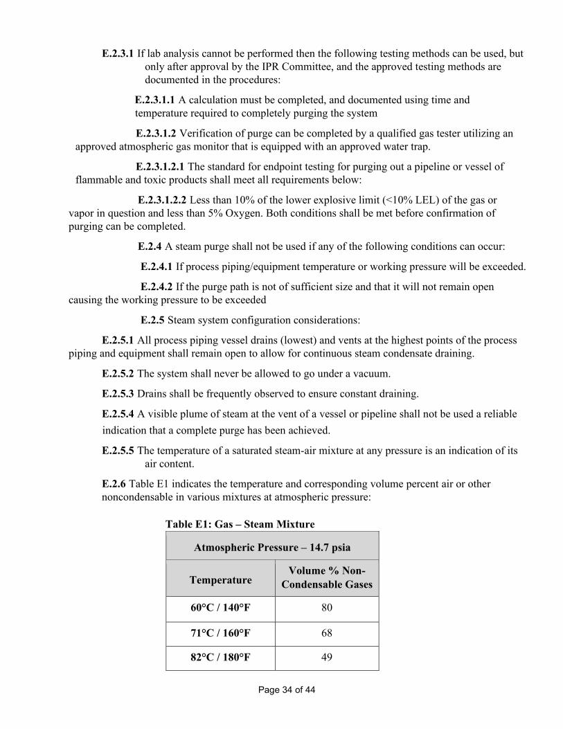
E.2.6 Table E1 indicates the temperature and corresponding volume percent air or other noncondensable in various mixtures at atmospheric pressure:
Table E1: Gas – Steam Mixture
Atmospheric Pressure – 14.7 psia
Temperature Volume % Non-
Condensable Gases
60°C / 140°F 80
71°C / 160°F 68
82°C / 180°F 49

Page 35 of 44
88°C / 190°F 36
93°C / 200°F 22
96°C / 204°F 15
98°C / 208°F 8
99°C / 210°F 4
99,5°C / 211°F 2
100°C / 212°F 0
E.3 Displacement with Water
E.3.1 Water may be used in approved purging applications for displacing vessel contents.
E.3.2 The advantages of purging with water are as follows:
E.3.2.1 Availability
E.3.2.2 Extinguishing properties
E.3.3 The disadvantages of purging with water are as follows:
E.3.3.1 The weight of water combined with the vessel may exceed the structural capacity.
E.3.3.2 Water freezes at 32°F / 0°C causing damage to process equipment.
E.3.3.3 Water contacting process equipment can carry contaminates in its run-off causing environmental impacts. Additionally, water is difficult to contain.
E.3.3.4 Water may react with certain substances creating vapors, heat, pressure, and damage to equipment.
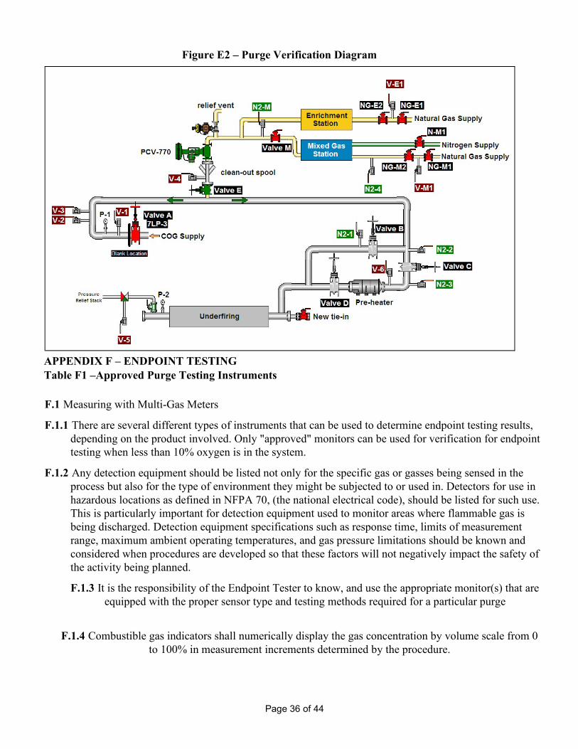
E.4 Purge Verification Diagram
E.4.1 A purge verification diagram (see Figure E2) should consist of but not limited to the following items: E.4.1.1 Vent points
E.4.1.2 Purge points
E.4.1.3 Purge path with direction
E.4.1.4 Isolation valves
E.4.1.5 Instrumentation
E.4.1.6 All gas sources identified E.4.1.7 Process
equipment
E.4.1.8 Blank locations.
Page 36 of 44
APPENDIX F – ENDPOINT TESTING Table F1 –Approved Purge Testing Instruments F.1 Measuring with Multi-Gas Meters
F.1.1 There are several different types of instruments that can be used to determine endpoint testing results, depending on the product involved. Only "approved" monitors can be used for verification for endpoint testing when less than 10% oxygen is in the system.
F.1.2 Any detection equipment should be listed not only for the specific gas or gasses being sensed in the process but also for the type of environment they might be subjected to or used in. Detectors for use in hazardous locations as defined in NFPA 70, (the national electrical code), should be listed for such use. This is particularly important for detection equipment used to monitor areas where flammable gas is being discharged. Detection equipment specifications such as response time, limits of measurement range, maximum ambient operating temperatures, and gas pressure limitations should be known and considered when procedures are developed so that these factors will not negatively impact the safety of the activity being planned.
F.1.3 It is the responsibility of the Endpoint Tester to know, and use the appropriate monitor(s) that are equipped with the proper sensor type and testing methods required for a particular purge
F.1.4 Combustible gas indicators shall numerically display the gas concentration by volume scale from 0 to 100% in measurement increments determined by the procedure.
Figure E2 – Purge Verification Diagram

Page 37 of 44
F.1.5 Lower Explosive (Flammability) Limit, LEL (LFL) monitors shall numerically display the gas concentration as a percent as a percentage of the LEL (LFL) from 0 to 100% in measurement increments determined by the procedure.
F.1.6 Oxygen monitors shall numerically display the oxygen concentration by volume from 0 to 25% or higher in measurements determined by the procedure.
F.1.7 Combustible gas indicators should display in increments of 1% or smaller. The procedure and the safety validation should indicate the maximum increment based on the gas being detected and the response time.
F.1.8 All portable gas monitors shall be bump tested daily or prior to use, (whichever is more is more frequent).
F.1.9 Portable gas monitors shall be calibrated monthly unless the device manufacturer recommends a more frequent calibration.
F.1.10 If the measured gas oxygen content is less than 10%, use of specialized meters or meter sampling techniques may be required. The use of a dilution tube or multi-gas meter with internal dilution tube is required for meters that cannot read properly in an Oxygen deficient environment. The dilution tube helps to achieve a more accurate reading of the gas’s combustible components. The tube draws atmospheric air so that the meter can function accurately. When dilution tubes are used, special training may be required to properly interpret the reading from the instrument since part of the gas stream will be outside the sampled space.
F.1.11 When using a dilution tube, always read the manufacturer’s instructions but in general remember the following:
F.1.11.1 Place the dilution tube onto the instrument; connect the dilution tube to the sampling wand or pipe and insert the wand / pipe through the designated sampling opening into the purged equipment.
F.1.11.2 In the location, where the dilution tube absorbs oxygen, the range shall be from 20% to 23.5%. The dilution tube shall never be placed into the piping/ vessel being purged.
F.1.11.3 The maximum length of the sampling probe shall be based on the manufacturer’s instructions.
F.1.11.4 Prevent oil, dust and steam from leaking into the dilution tube.
F.2 Measuring with sampling glass (bottle) for lab analysis:
F.2.1 A sampling glass shall be provided by the testing Lab. The Lab fills the glass with colored water.
F.2.2 Inspect and ensure that sampling glass fittings are functioning properly.
F.2.3 Using a rubber hose, connect the purged equipment (using a testing valve on purged equipment) to the top fitting of the sampling glass and then open the sampling glass top fitting while keeping the sample glass in a vertical position. (Figure F1)
F.2.4 Ensure the equipment releasing valve is in a closed position, in order to prevent outside atmosphere flow back into the sampling glass.
F.2.5 Keep the sampling glass in vertical position.

Page 38 of 44
F.2.6 Open the bottom fitting on the sampling glass, and let the water slowly run out. The water running out of the sampling glass creates a vacuum, which sucks the gas from the purged equipment into the sampling glass.
F.2.7 DO NOT let all water flow out; approx. 1 inch shall remain in the bottom part of the sampling glass.
F.2.8 Close the bottom and the top fittings on the sampling glass.
F.2.9 Disconnect the hose and open the releasing valve on the equipment.
F.2.10 When purging with steam, the sampling wand or pipe shall be equipped with a water trap, to catch water condensate. Cool tubes are also recommended when testing steam purge endpoints.
Figure F1 – Arrangement For Lab Sample Bottle Use
F.3 Important Cautions
F.3.1 The only accurate endpoint test for steam purges is a lab analysis.
F.3.2 The use of personal atmospheric monitors to verify purge results shall be prohibited.
F.3.3 Igniting leaking gas out of the sampling valve to verify purging shall be prohibited.

Page 39 of 44
APPENDIX G – IPR ACTIVITY SAFETY VALIDATION CHECKLIST G.1 IPR Activity Safety Validation Checklist
Scope of Work (note gas or liquid streams involved, SDS) Location of Meeting Date of Meeting
Department Division
Affected Facilities Procedure
HJP #
SJP #
IPR Process
PPC
QPP(s)
IPRC
Y N SSP Ref
General Walk through Inspection of the Work Site 4.3.2
Flammable or Combustible Materials, (properties known and planned for) 4.3.3
Toxic Materials, (properties known and planned for) 4.3.4
Purge medium, (properties known and planned for) 4.3.5
Qualified Purge Participants Available 3.5.15
Purge Endpoint Testers Available 3.5.16
Calibrated Testing Devices Available F.1
A Copy of the IPR Activity Procedure Posted at the Job Site 3.5.18
Work Permits Required, (hot work, confined space and others) 3.5.17
Notify Other Affected Departments 4.3.8
Contact utility or third party gas provider if there could be impact to their systems 4.3.6
Evacuation Signal & Emergency Response Plan 4.3.11
Assembly/Muster Area 4.3.12
Planned Escape Routes - 2 Means of Egress 4.3.12
Exclusion zones have been identified and plans to limit access including hot work exist 6.8

Page 40 of 44
Stand down conditions exist and are communicated in the HJM 4.3.1
Topography has been considered for gas release dispersion, rescue vehicle access and other factors 6.7.6
Rescue Breathing Air & Resuscitator 7.2
Special Respirators/Cartridges 7.2
Noise control has been considered for its impact to personnel standards and neighbors 4.3.8
Temporary piping for purge medium or discharge, (designed to ASME B31.3 requirements) 4.3.10
PPE requirements planned for each type of person and function on the job 7.2
Verify all training records including contractors 3.10 / 4.1.2
Fire Protection Requirements 4.3.9
Fire Hose 4.3.9
Manned 4.3.9
Unmanned 4.3.9
Dry 4.3.9
Pressurized 4.3.9
Fire Extinguisher 4.3.9
Appropriate Type Identified 4.3.9
Isolation (IPR-SSP Section 5.0) All Sources Capable of Being Locked Out or Tagged Out 4.4.1
Isolation & Lockout List 4.4.1
Blank & Disconnect List 4.4.2
Isolation & Lockout Diagram, (including instrumentation) 4.4.7
ECP Attached 4.4.1
Positive Isolation Requirement (NO, Attach Approved Exemption) 5.2.2
Confined Space Entry 5.2.2.1
Possible Accumulation of Gases Inside Buildings or Poorly Ventilated areas 5.2.2.2
Combustible Gases in Close Proximity to Oxidizers and Electric Power Lines 5.2.2.3
Positive Isolation Device(s) Used 5.2.3
Slip Blank 5.2.3.1
Blind Flange 5.2.3.2
Goggle Valve 5.2.3.3
Disconnect, Cap or Plug 5.2.3.4
Positive Isolation Method Used 5.2.3
Double Block and Bleed (Special Requirements Satisfied) 5.2.3.5
Non-Positive Isolation Method(s) Used 5.2.5
Water / Nitrogen Sealed Double Disc Gate Valve 5.2.5.1
Double Block and Pressurize 5.2.5.2
Water Seal Leg 5.2.5.3
Double Block and Bleed 5.2.5.4

Page 41 of 44
Non-Positive Isolation Device(s) Used 5.2.4
Lubricated Plug Valve 5.2.4.1
Ball Valve 5.2.4.2
Stopple 5.2.4.3
Inflated Bag 5.2.4.4
Cryogenic Freeze-plug 5.2.4.5
Single Disc Gate Valve 5.2.4.6
Butterfly Valve 5.2.4.7
Globe Valve 5.2.4.8
Double Disc Gate Valve 5.2.4.9
Purging (IPR-SSP Section 6.0) Purge Diagram (with Isolation and Lockout Diagram) 4.4.6
Purge processes being used for this project 6.0
Displacement (Sweep or Slug) E.1.1
Dilution E.1.2
Trickle E.1.3
Purge Verification 6.9
Communication Method for Purge Commencement and Purge Completion, (Cleaning) 4.3.8
Consider local signals for workers in the area and general notice to the facility overall 4.3.8
Purge Path Through All Piping including Dead legs 6.2
Venting Gas Through a Flare System 6.7.1
Regulatory Permits Required, (gas or liquid discharges) 3.5.17
Venting Gas Indoors NOT ALLOWED 6.7.2
Venting Gas Outdoors 6.7.2
Vents equipped with Shut Off Valves 6.7.3
Vent discharge static electricity and possible grounding 6.7.10
Vent Points Accessible 6.7.4
Vent Discharge considered Volume, Velocity, & Spec.Gravity of Purged Materials 6.7.5
Vent Discharge away from Building Openings & Ignition Sources 6.7.5
Vent Discharge considered Weather, Wind Direction, Traffic, Personnel 6.7.6
Hydrogen Venting Through a Flame Arrestor 6.7.9
Air Monitoring of Vent(s) 6.8
Air Monitoring of Buildings Near Vent(s) 6.8.1
Air Monitoring of Repaired Area(s) 6.8.2
Endpoint test pressure: Positive pressure, 2 in w.c. or less 7.2.5
Purge Out of Service to < 10% of the LEL, <5% Oxygen, <TWA for Toxics 6.9.4
Purge Into Service to < 5% Oxygen 8.2.4.1
Purge Into Service to 90% Gas by Volume (OR, as per IPR Activity Procedure) 8.2.10.1

Page 42 of 44
Purge Maintained at Positive Pressure to Prevent Air Infiltration 6.12.3.4
Purge Medium Pressure Regulation 6.13.2
Gauges Monitored 6.13.4
Maximum Purge Pressure Determined 6.13.3
All Purge Equipment Rated for Use & Protected From Damage 6.13.2
Cryogenic Purging Equipment Procedures & PPE 6.13.7
Cryogenic Purging Equipment Rated for Use 6.13.8
Vaporization of Cryogenic Purge Medium 6.13.9
Sufficient Purge Medium Supply & Backup 6.15
Purge Medium 6.15.1.6
Nitrogen 6.15.1.6.1
Steam 6.15.1.6.3
Argon 6.15.1.6.2
Water 6.15.1.6.4
Blanking (IPR-SSP Section 7.0) – If no, skip section. Blank and Disconnect Form 4.4.2
Blank Diagram (with Isolation and Lockout Diagram and/or Purge Diagram) 4.4
Blanking Field Verification 4.4
Bolts Rehearsed D.1
Breathing Air 7.2
Maintain Positive Purge Pressure, 2 in w.c. or less 7.2.5
Ventilation Needs 7.2.7
Electrical Bonding or grounding of Flanges and Piping. 7.3.1
Tool Requirements 7.3
Ignition Sources Considered (including non-intrinsically safe, incendiary, non-explosion proof electrical and electronic devices, static electricity and mobile equipment) 7.4
Blank Thicknesses Listed / Blank Thickness Program 7.5.1
Restriction of Personnel in Area 7.6
Restricted Area Established 7.6
Re-introduction and Process Start-up – if no, skip section Pressure/Leak Test Media Selected 8.1
Pre-Blank Removal Pressure/Leak Test at Specified Pressure 8.1.1
Post-Blank Removal Pressure/Leak Test at Specified Pressure 8.1.2
Special Hazards– if no, skip section Pyrophoric Materials Expected 9.1
Precautions to Address Pyrophorics 9.1.2
COG Condensate Expected 9.2
Precautions to Address COG Condensate 9.2.2
Gas Main Deposits Expected 9.3
Precautions to Address Gas Main Deposits 9.3.2

Page 43 of 44
Purge Medium Hazards Addressed 9.4
Precautions to Purge Medium Hazards Addressed 9.4.3
Vacuum Systems 9.5
Determination if Flammable or Explosive Mixture Possible 9.5.1
Determination of Air Infiltration Points 9.5.1
Sample Ports & Techniques 9.5.2
Minimizing Process & Operational Changes 9.5.3
Nitrogen or Steam Dilution of Air 9.5.4
Vacuum Measurement 9.5.5
Dedicated Person to Monitor Process Parameters/Gas Conditions 9.5.6
Minimizing Air Infiltration at Flanges & Bolt Holes 9.5.7
Special Emergency 9.5.8
Other Hazards Not Listed (Document below) Purge Monitoring and Instrumentation 6.8
Verify that monitoring instruments are correct for the job 6.13.4
Intrinsically safe if needed 7.4.1
Proper capabilities for what is being measured, (dilution tube) F.1.10
Meter meets Corporate guidelines F.1.1
Verify gas tester training 3.7.1
Sampling plan exists with provisions for safe continuous monitoring 9.5.2
Independent Safety Validation (Printed Name and Signature Required)
Company Representative
Contractor Representative
(if applicable)
Company Name
Address

Page 44 of 44
G.2 IPR Activity Safety Validation Checklist Definitions Table G1 – IPR Activity Safety Validation Checklist Definitions
Administration
Term Definition
Scope of Work This section should contain the system name and type the work is to be done. The type of purge that will be performed per section 6.5 of the IPR SSP will be listed along with drawing Numbers and any single line sketches of the affected System.
Date of Meeting This is the Date of the HJM that will be conducted for any new IPR procedures and an amendment record will be kept per the HJM form as a record of any and all changes to the procedures.
Affected Facilities
Identify which facilities might be impacted by the process. This would mean facilities that might be getting less gas from a process because of isolation of lines. It could also mean facilities will have traffic flow through them or that might need to be barricaded because of possible venting of gasses and the potential for ignition sources to occur from traffic or operations.
HJP # This is the number assigned by the HJM process referring to this specific Job/procedure.
SJP #
Identify any SJPs (Safe Job Procedures) that relate to this work. Print them out and have them available for the team. Makes sure that the implementation team gets to see them, including the contractors, and make sure they are reviewed during the procedure development
IPR Process This section should contain the names and roles of the employees involved in the development and execution of the procedure.