isp stitching & bindery products a division of samuel ... · preventive maintenance ......
TRANSCRIPT

OWNERSMANUAL
ISP Stitching & Bindery ProductsA D i v i s i o n O f S a m u e l S t r a p p i n g S y s t e m s
ISP Stitching & Bindery Products
2
Stitch'n Fold
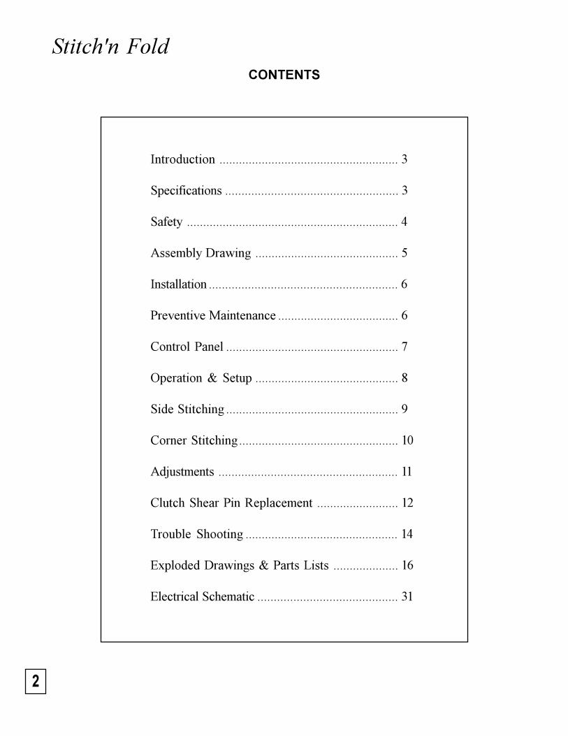
Introduction ....................................................... 3
Specifications ..................................................... 3
Safety ................................................................. 4
Assembly Drawing ............................................ 5
Installation .......................................................... 6
Preventive Maintenance ..................................... 6
Control Panel ..................................................... 7
Operation & Setup ............................................ 8
Side Stitching ..................................................... 9
Corner Stitching................................................. 10
Adjustments ....................................................... 11
Clutch Shear Pin Replacement ......................... 12
Trouble Shooting ............................................... 14
Exploded Drawings & Parts Lists .................... 16
Electrical Schematic ........................................... 31
CONTENTS

3
ISP Stitching & Bindery ProductsA D i v i s i o n O f S a m u e l S t r a p p i n g S y s t e m s
INTRODUCTION
Simple Operation: Just load your booklet and it is automatically jogged, stitched, folded, and dischargedonto an accumulating output conveyor. Side stitching, corner stitching, and folding projects, with orwithout stitching, are easily accomplished.
Advanced Technology: Stitch'n Fold uses ISP's patented magnetic stitching head technology, pro-viding the reliability and economy of wire stitching. Dual sets of folding rollers assure consistent,professional results. For safety, interlocked access guards prevent machine operation when open.
Improved Productivity: With Stitch'n Fold , you can jog, stitch, and fold more than 65,000 bookletsat a maximum speed of 2,000 finished booklets per hour - without stopping to reload staples. Stitch'n Fold 's variable work thickness capacity handles from 2 sheets to a one hundred page booklet withno setup changes or adjustments.
Lower Operating Costs: The Stitch'n Fold replaces expensive preformed staples with inexpensivebookbinding wire; you save on material costs and nonproductive downtime.
SPECIFICATIONS - MODEL: B1000
Unit Weight: 190 Pounds
Speed: Up to 2,000 booklets per hour
Capacity: 2 to 25 sheets of 20# bond (100 page book)
Re-load: 65,000 booklets per spool of wire
Paper Size: Min. 5.5" x 8.5" Max. 11" x 17" (also: A5 to A3)
Booklets: Min. 4.25" x 5.5" Max. 8.5" x 11"
Stitch Space: 5.5" on 8.5" or 11" tall books 2.75" on 5.5" tall books
Counter: Resettable 6-digit electronic counter
Folder: Knife/Buckle folder with dual folding rollers
Squaring: Side jog plus full length tape feed
Output: Continuous conveyor
Footprint: 20" x 30"
Dimensions: Height 30" Width 20" Depth 50"
Modes: Stitch and Fold, Stitch, Fold, Corner Stitch, Side Stitch
Electrical: Standard outlet - 115 Volts, 60 Hz, 10 Amps (1/4 HP)

4
Stitch'n FoldSAFETY
A. Clear Plastic Front Guard: Blocks access topoint of operation of stitching heads. An elec-trical interlock keeps the machine turned offunless this hinged guard is closed. Do notstick your fingers under the front guard!
B. Clear Plastic Top Guard: Blocks access tomechanism that drives the stitching heads. Anelectrical interlock keeps the machine turnedoff unless this guard is closed. Do not stickyour fingers under the top guard!
C. Vacant Head Guards: Close gaps in top guard.One of the inverted "L" shaped guards ismounted in each empty stitching head position.Whenever the stitching heads must be reposi-tioned for a new job, remove the guard fromthe spot where the head needs to be, and re-mount the guard in the vacated spot.
D. Right Side Cover: Blocks access to mecha-nisms that can pinch or cut.
E. Left Side Cover: Blocks access to dangerouselectric voltage and mechanisms that can pinchor cut. Be sure to disconnect electrical powerbefore removing this cover.
F. Front Cover: Blocks access to dangerous elec-tric voltage and mechanisms that can pinch orcut. Be sure to disconnect electrical powerbefore removing this cover.
G. Rear Cover: Blocks access to mechanisms thatcan pinch or cut. Do not stick your fingersbeyond this cover!
H. Belt Guard: Blocks access to a pinch point.
I. Sensor Guard: Blocks access to low voltageconnection.
J. Discharge Guard: Blocks access to pinchpoints.
SAFETY GUARDS
1. Make sure electrical power is turned off be-fore performing any adjustment or mainte-nance.
2. Keep hands, hair, tools, and clothing clear ofstitching area.
3. Become familiar with the moving componentsof your machine. Keep fingers away fromareas that could pinch or cut.
4. A well maintained machine is a safer machine.Clean and lubricate the machine at regular in-tervals. Check machine daily for broken orworn parts. Replace as necessary. DO NOTattempt to operate the machine if a part is bro-ken.
5. See "SAFETY GUARDS" below! If you areunsure how to safely operate your Bookletmaker,contact your Service Representative.
SAFETY PRECAUTIONS AND PROCEDURES
DANGER
KEEP HANDS CLEAR OF STITCHING AREA AND ANY MOVING PARTS!
NEVER OPERATE MACHINE WITHOUT ALL GUARDS IN PLACE!

5
ISP Stitching & Bindery ProductsA D i v i s i o n O f S a m u e l S t r a p p i n g S y s t e m s
ASSEMBLY DRAWING
Main Table
H. Belt Guard
F. Front Cover
Secondary Table
Delivery Table
E. Left Side Cover
G. Rear CoverI. Sensor Guard
C. Vacant Head Guards
B. Clear Plastic Top GuardRight Side Guide
D. Right Side Cover
A. Clear Plastic Front Guard
Stitching Heads
Main TableBelt
Ski
Adjusting Knob
Left Side Guide
J. Discharge Guard

6
Stitch'n FoldINSTALLATION
BEFORE UNCRATING:
Examine the crate for visible damage. If the crateis damaged, the machine might be damaged. Notifythe carrier who delivered the machine.
UNCRATING THE MACHINE:
Carefully remove the machine from its container.Lift the machine by grasping its strong framework.Tugging on cables, covers, or other delicate com-ponents could cause damage.
Examine the machine for damages incurred duringshipping. Do not install a damaged machine.Notify the carrier immediately.
Be sure to get a signed copy of the CarrierInspector's Report of the damage incurred. Yourservice representative will assist you in determin-ing the cost of repairs.
ELECTRICAL POWER:
The power cord can be plugged into any 115V, 60Hz, 1 Phase, 15 Amp circuit. The machine drawsless than 10 amps.
LOADING WIRE:
Use only approved stitching wire, part number415-0225. Lift the top plastic guard to reach thewire spool studs. The first items on each studshould be the conical spring followed by a whiteplastic washer. Next goes the coil of stitchingwire followed by a large plastic washer. Finally,a retaining pin holds everything in place.
The coils of stitching wire should be mounted sothe wire comes off upward from the backside.
To thread the wire into the stitching heads, seeinstructions in the stitching head owners manual.
PREVENTIVE MAINTENANCE
LUBRICATION:
Disconnect electrical power. Next, remove thefront cover. Provide table space to lay down theleft side cover next to the machine; they are con-nected by electrical wires. Remove both sidecovers.
Use SAE-20 oil to lubricate porous bronze bear-ings, needle bearings, chains, and shafts.
Use approved stitcher head lubricant, part numberCA9640, to lubricate the stitching heads everytime a new coil of stitching wire loaded. Cleanand lubricate the magnetic rotator. Lubricate thedriver bar and the bender bar latch. See stitchinghead owners manual for detailed lubrication in-structions.
CLEANING:
Use alcohol to clean the belts.
Use a 50-50 mixture of alcohol and water to cleanthe folding rollers.

7
ISP Stitching & Bindery ProductsA D i v i s i o n O f S a m u e l S t r a p p i n g S y s t e m s
MAIN CONTROL PANEL
STITCHON OFFON OFF
COUNTS
A. Pilot Light: Glows to indicate that electricalpower is turned on.
B. Power On: Black rocker switch turns on power.Pilot glows; motor runs if motor selector switchis in "On" position.
C. Power Off: Red rocker switch turns off power.
Note: Opening the front or top plastic guardsshuts off the machine. It must be restarted asabove.
AUXILIARY CONTROL PANEL
D. Counter: Digital counter records the numberof sets that pass through the machine. A manualreset button returns the counter to zero aftereach job. The reset button can be locked toprevent accidental reset.
E. Stitch On/Off: Selector switch chooses modeof operation: "On" for stitching jobs or "Off"for folding without stitching.
A B C D E
A. Motor On/Off: Selector switch allows motorto be turned off with power still turned on.
B. Motor Jog: Rocker switch cycles the stitchers.First, turn off motor. Then, slide a sheet ofpaper into the stitching position until it tripsthe limit switch by the gate (4LS). Now,press and quickly release the jog switch tocycle the stitchers.
C. DC Fuse: Fuse protects transformer. If thisfuse fails, none of the 24VDC components willoperate. Replace with proper .75A fuse.
D. Main Fuse: Fuse protects entire machine. Ifthis fuse fails, power cannot be turned on.Replace with proper 10A fuse.
ON OFF
FUSE
JOG
MOTOR
DC
MAIN
FUSE
A
B
D
C

8
Stitch'n FoldOPERATION & SETUP
Bookletmaking & Basic AdjustmentsSee Following Sections For Corner Stitching Or Side Stitching
scale on the main table. Note: the space betweenthe side guides will be about .30" more than thepaper width. This extra space allows for the rightside guide to jog the paper before it is stitched.
For 5.5" x 8.5" paper and some odd sizes ofpaper, the side guides will interfere with the outerbook stops on the stitcher gate. Remove the outerstops by lifting open the top plastic guard andusing the accessory 1/16" hex wrench to loosenthe stops. Be careful not to drop the stops insidethe machine.
PAPER LENGTH:
Adjust the gates for paper length. For instance,for 8.5" x 11" paper, the gates must be set for the11" length. Place a sheet of paper on the maintable between the side guides and slide it underthe ski until it stops against the first gate. Whileholding the paper against the gate, turn the adjust-ing knob under the left hand side of the table untilthe paper is aligned with the 11" mark on thescale. (Clockwise rotation moves the paper out.)This single adjustment takes care of both the stitch-ing gate and the folding gate. Also, see TimerGate Adjustment on page 11.
Adjust the booklet tray at the end of the deliverytable to match the booklet size. Loosen the knobunder the tray, and slide the tray to the properposition.
Finally, adjust the position of the delivery tablewheels. Loosen the thumb screw between thewheels, and slide the wheels to a position thatsuits the booklet size.
BOOKLETMAKING
STITCHING HEADS:
Make sure the stitching heads are mounted in theproper positions to match the paper size. For 5.5"x 8.5" (also A5) paper, the heads must be mountedin the two positions closest to the belt on the maintable. One head is mounted just to the left of thebelt, and the other head is mounted just to the rightof the belt. These head locations will provide astitch spacing of 2.75". For 8.5" x 11" or 11" x17" (also: A4 or A3) paper, each head is mountedin the second position to the left and the right ofthe center belt. These head locations provide5.50" stitch spacing.
To move a stitching head to a new position, firstlift open the top plastic guard. Loosen and re-move the knob/bolt from the back of the head.Pull the head forward until it comes off of thelocating pin, and slide it over to the desired lo-cation. Slip the head onto the new locating pin,and be sure that the driving lug on the upperbackside of the head engages the slot in the headdriving bar. Replace the knob/bolt (and its washerand lockwasher), and tighten it securely.
PAPER WIDTH:
Adjust the side guides for paper width. For in-stance, if 8.5" x 11" paper is being used to makea 5.5" x 8.5" booklet, the side guides must be setfor the 8.5" width. First, lift open the front plasticguard. Loosen the thumb screw on each sideguide, and slide each guide sideways until itsinner edge is aligned with the 8.50" mark on the

9
ISP Stitching & Bindery ProductsA D i v i s i o n O f S a m u e l S t r a p p i n g S y s t e m s
Off Center Fold
Proper Fold
SIDE STITCHING
Side stitching can be done with 5.5" x 8.5" or 8.5"x 11" (also: A4 or A5) paper. In either case,mount the heads for 5.50" stitch spacing.
Adjust the side guides for paper length. For in-stance, if 8.5" x 11" paper is being side stitched,the side guides must be set for the 11" length.Align the inner edge of each side guide with the11" mark on the table scale.
Adjust the stitching gate for paper width. Forinstance, for 8.5" x 11" paper, the gate must be setfor the 8.5" width. First, lift open the front plasticguard. Place a sheet on the table between the sideguides, and slide it under the ski until it stopsagainst the gate. Turn the crank until the trailingedge of the paper is just in front of the clinchers.An alternative method is to set the gate for makingbooklets with 11" x 17" paper and then turning thecrank clockwise to back out the gate about 1/8".
Lower the folding gate by reaching under the sec-ondary table and pressing the hanging latch. Theside stitched sets will drop off the end of thesecondary table unfolded.
Check the finished booklet. If the stitches areproperly located on the fold, but the fold is offcenter (see end view below), adjust the gates byturning the crank until sets will fold precisely inhalf.
Finally, if the fold is not quite square (see below),the wing nuts can be adjusted individually.
OPERATION & FINE ADJUSTMENT:
Turn on power and select "STITCH ON" and"MOTOR ON". Square up a set of paper sheetsby hand, and lay the front edge on the table be-tween the side guides. Push until the front edgeis under the ski, and then let go. The set will beautomatically stitched, folded, and ejected ontothe output conveyor.
If the stitches are off the fold (see below), openthe booklet flat and measure to see if the stitchesare centered on the length of the paper. Turn thecrank until stitches are placed precisely on thecenter of the paper. Next, locate the two wingnuts below the back end of the secondary table.Turn both wing nuts equally in small incrementsuntil booklets will fold precisely on the stitches.

10
Stitch'n Fold
instance, for 8.5" x 11" paper, the gate must be setfor the 8.5" width. First, lift open the front plasticguard. Place a sheet on the table between the sideguides, and slide it under the ski until it stopsagainst the gate. Turn the crank until the trailingedge of the paper is just in front of the clinchers.
Lower the folding gate by reaching under the sec-ondary table and pressing the hanging latch. Thecorner stitched sets will drop off the end of thesecondary table unfolded.
CORNER STITCHING
Corner stitching can be done with 5.5" x 8.5" or8.5" x 11" (also: A4 or A5) paper. In all cases,mount one head in the far left position. The otherhead may be removed or left in any position withoutwire.
Two accessory guides must be mounted on the lefthand side for corner stitching. First, adjust thestandard left side guide as far as possible to theleft. Using thumb screws, attach the corner stitchblock (inverted "L" shaped part) to the two holesin the left side guide.
Next, lift open the top plastic guard. Using twothumb screws, attach the corner stitch guide (11"long bar) to two holes in the table on the far leftunder the coil of stitching wire. The angle on thebar should face the front and middle of the ma-chine.
Adjust the right side guide for paper length. Forinstance, if 8.5" x 11" paper is being cornerstitched, the side guide must be set for the 11"length. Align the inner edge of the right side guidewith the table scale as follows:
11" paper 11" mark8.5" paper 6" markA4 paper 12.38" markA5 paper 6.54" mark
Adjust the stitching gate for paper width. For
Index Part Part Name NumberNumber Number Required
1 RBM1341F Corner Stitch Block 12 CGG44B Thumb Screw 2* RBM1322F Corner Stitch Guide 1* CGG44 Thumb Screw 2
12
* Not shown.
FOLDING ONLY
Adjust the machine for paper size according to theinstructions for bookletmaking. However, thestitching heads may be left in any mounting posi-tions. On the control panel, select "STITCH OFF".

11
ISP Stitching & Bindery ProductsA D i v i s i o n O f S a m u e l S t r a p p i n g S y s t e m s
ADJUSTMENTS
STITCHING CLUTCH
The stitching heads are controled by a single revo-lution wrap spring clutch. This clutch must beadjusted to stop the stitching heads in the properposition. First disconnect electrical power. Thenremove the front cover and the right side cover.The clutch is located inside the cabinet on theshaft toward the left side, and it is bronze andblack in color.
Stop Collar
Actuator
Pin
Set Screw
Adjusting Collar
Clutch In Neutral Position
Remove stitching wire from the stitching heads.Trip the clutch by by pulling down on the actuatorwith the tip of a small screw driver. On the righthand side of the machine, slowly turn the largespoked wheel clockwise until the first set screwin the adjusting collar is facing forward. Use a5/64 hex wrench to loosen the set screw. Con-tinue to turn the wheel until the second set screwis facing forward; loosen the screw.
Turn the wheel until the stop on the stop collarhits the actuator. Now turn the wheel until theproper stopping position is reached. Watch thestitching heads on the up stroke. When the benderbars reach the top of the windows in the faceplates, turn the wheel slightly more. Be sure thatboth wire grips are still open. This is the properstopping position. If you have gone too far, justcontinue to turn the wheel until you return to theproper position.
Finally, while still in the proper stopping posi-tion, trip the clutch and turn the wheel until one ofthe set screws is facing forward. Carefully holdthe adjusting collar so that the stop collar pin iscentered in the opening in the adjusting collar.Tighten the set screw securely. Turn the wheeland trip the clutch, if necessary, until the secondset screw can be tightened.
PAPER SIZE:
GATE TIMER
11x17A3
8.5x115.5x8.5A4, A5
GATE TIMER
The adjusting knob for the gate timer is located onthe back of the machine's left side cover. It con-trols the amount of time that the stop gate is helddown each cycle after the stitches have been driveninto the booklet. Longer booklets need more timeto get past the gate, and the next cycle cannot startuntil the gate has returned.
For 11" x 17" paper, set the knob as shown. Theknob can be left in this position for other papersizes, but the the gate will be held down longerthan necessary. For faster feed rates with smallerpaper, turn the knob to the 8.5x11 position.

12
Stitch'n FoldREPLACEMENT OF CLUTCHSHEAR PIN
1. Unplug machine.
2. Remove side covers and front cover.
3. See exploded view of head drive shaft onpage 22.
4. Disconnect the pull rods from both head drivecranks (#19). Remove the left side head drivecrank.
5. Loosen flange bearing set screws (#22) - bothright and left sides.
6. Mark the position of the side jog actuator cam(#43), then loosen both set screws.
7. Remove screws (#34) from the switch andclutch bracket (#33), and gently lay the bracketdown. There is no need to remove wires.
8. Release the idlers on both drive pulley belts.
9. The head drive shaft (#13) should now movefreely from left to right.* Move the shaft tothe right just enough to get an allen wrench onthe three socket head screws (#31) holding thehead drive pulley (#27) to the clutch. Removeall three.* Note: If the unit has a back jog, it might benecessary to mark the position of the limitswitch cams and loosen them in order to movethe shaft far enough to the right.
10. Slide the head drive pulley (#27) and the knifedrive pulley (#29) to the left.
11. A collar on the stitch clutch (#30) should nowbe visible. A pin (#37) connects the collar tothe shaft. Remove the sheared and replace.
12. Reassemble by reversing the disassembly pro-cedure.
Stitcher Head Drive Clutch
Clutch Collar
Shear Pin

13
ISP Stitching & Bindery ProductsA D i v i s i o n O f S a m u e l S t r a p p i n g S y s t e m s
14
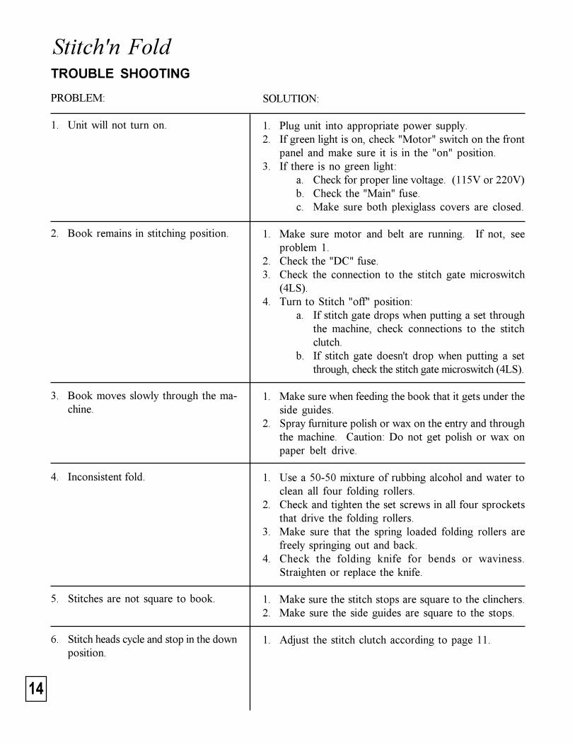
Stitch'n FoldTROUBLE SHOOTING
PROBLEM:
1. Unit will not turn on.
2. Book remains in stitching position.
3. Book moves slowly through the ma-chine.
4. Inconsistent fold.
5. Stitches are not square to book.
6. Stitch heads cycle and stop in the downposition.
SOLUTION:
1. Plug unit into appropriate power supply.2. If green light is on, check "Motor" switch on the front
panel and make sure it is in the "on" position.3. If there is no green light:
a. Check for proper line voltage. (115V or 220V)b. Check the "Main" fuse.c. Make sure both plexiglass covers are closed.
1. Make sure motor and belt are running. If not, seeproblem 1.
2. Check the "DC" fuse.3. Check the connection to the stitch gate microswitch
(4LS).4. Turn to Stitch "off" position:
a. If stitch gate drops when putting a set throughthe machine, check connections to the stitchclutch.
b. If stitch gate doesn't drop when putting a setthrough, check the stitch gate microswitch (4LS).
1. Make sure when feeding the book that it gets under theside guides.
2. Spray furniture polish or wax on the entry and throughthe machine. Caution: Do not get polish or wax onpaper belt drive.
1. Use a 50-50 mixture of rubbing alcohol and water toclean all four folding rollers.
2. Check and tighten the set screws in all four sprocketsthat drive the folding rollers.
3. Make sure that the spring loaded folding rollers arefreely springing out and back.
4. Check the folding knife for bends or waviness.Straighten or replace the knife.
1. Make sure the stitch stops are square to the clinchers.2. Make sure the side guides are square to the stops.
1. Adjust the stitch clutch according to page 11.
15
ISP Stitching & Bindery ProductsA D i v i s i o n O f S a m u e l S t r a p p i n g S y s t e m s
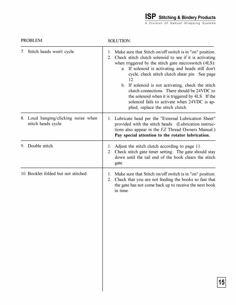
PROBLEM:
7. Stitch heads won't cycle.
8. Loud banging/clicking noise whenstitch heads cycle.
9. Double stitch.
10. Booklet folded but not stitched.
SOLUTION:
1. Make sure that Stitch on/off switch is in "on" position.2. Check stitch clutch solenoid to see if it is activating
when triggered by the stitch gate microswitch (4LS):a. If solenoid is activating and heads still don't
cycle, check stitch clutch shear pin. See page12.
b. If solenoid is not activating, check the stitchclutch connections. There should be 24VDC tothe solenoid when it is triggered by 4LS. If thesolenoid fails to activate when 24VDC is ap-plied, replace the stitch clutch.
1. Lubricate head per the "External Lubrication Sheet"provided with the stitch heads. (Lubrication instruc-tions also appear in the EZ Thread Owners Manual.)Pay special attention to the rotator lubrication.
1. Adjust the stitch clutch according to page 11.2. Check stitch gate timer setting. The gate should stay
down until the tail end of the book clears the stitchgate.
1. Make sure that Stitch on/off switch is in "on" position.2. Check that you are not feeding the books so fast that
the gate has not come back up to receive the next bookin time.
16
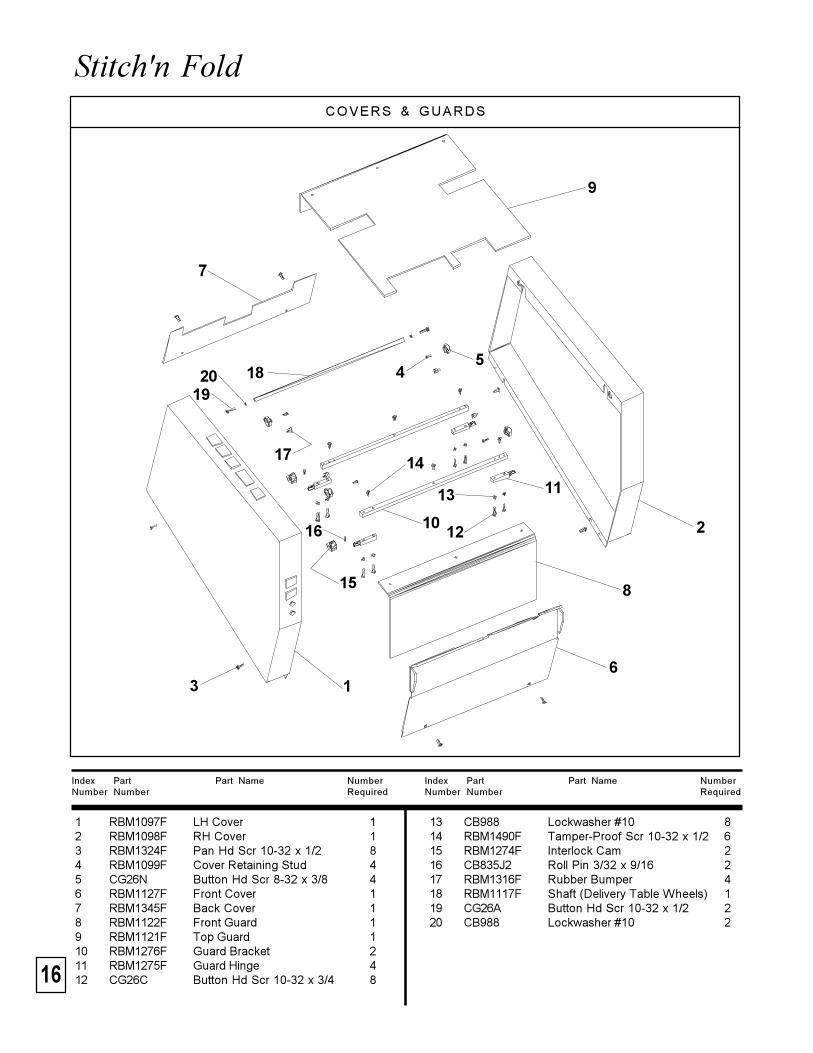
Stitch'n FoldCOVERS & GUARDS
Index Part Part Name NumberNumber Number Required
Index Part Part Name NumberNumber Number Required
13 CB988 Lockwasher #10 814 RBM1490F Tamper-Proof Scr 10-32 x 1/2 615 RBM1274F Interlock Cam 216 CB835J2 Roll Pin 3/32 x 9/16 217 RBM1316F Rubber Bumper 418 RBM1117F Shaft (Delivery Table Wheels) 119 CG26A Button Hd Scr 10-32 x 1/2 220 CB988 Lockwasher #10 2
1 RBM1097F LH Cover 12 RBM1098F RH Cover 13 RBM1324F Pan Hd Scr 10-32 x 1/2 84 RBM1099F Cover Retaining Stud 45 CG26N Button Hd Scr 8-32 x 3/8 46 RBM1127F Front Cover 17 RBM1345F Back Cover 18 RBM1122F Front Guard 19 RBM1121F Top Guard 110 RBM1276F Guard Bracket 211 RBM1275F Guard Hinge 412 CG26C Button Hd Scr 10-32 x 3/4 8
18
16
16
8
19
13
14
3
11
4
15
2
5
1210
9
7
17
20
17
ISP Stitching & Bindery ProductsA D i v i s i o n O f S a m u e l S t r a p p i n g S y s t e m s
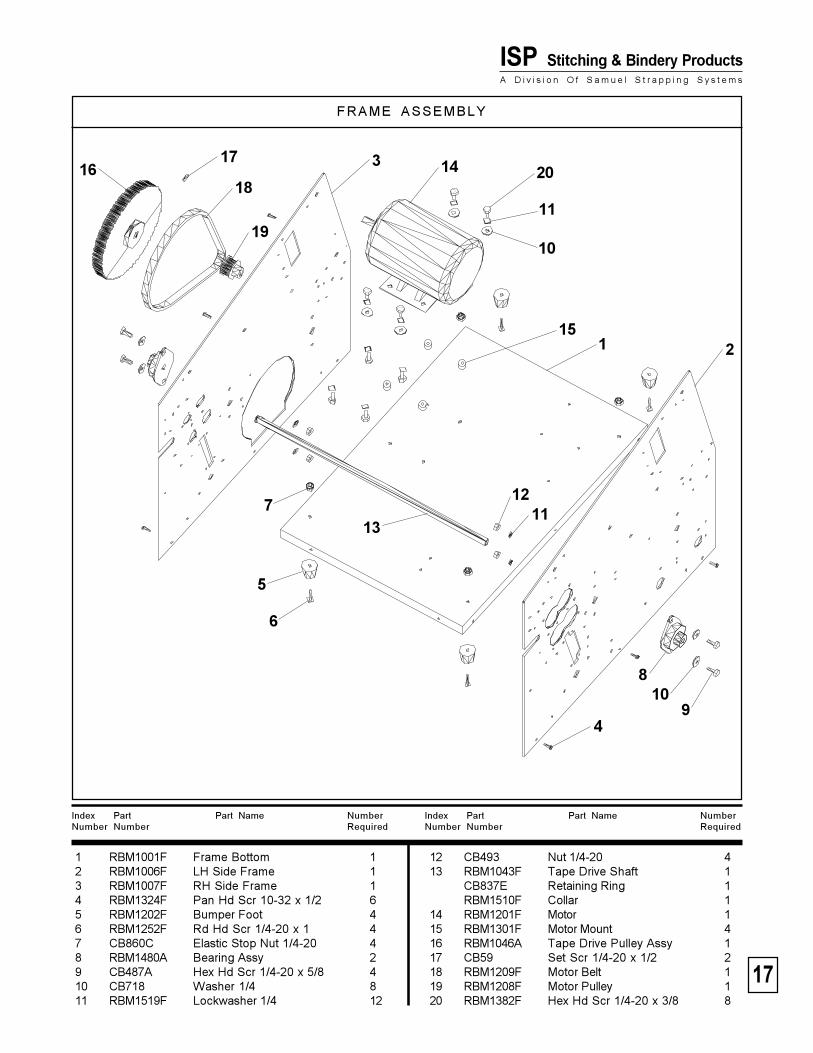
FRAME ASSEMBLY
Index Part Part Name NumberNumber Number Required
Index Part Part Name NumberNumber Number Required
12 CB493 Nut 1/4-20 413 RBM1043F Tape Drive Shaft 1
CB837E Retaining Ring 1RBM1510F Collar 1
14 RBM1201F Motor 115 RBM1301F Motor Mount 416 RBM1046A Tape Drive Pulley Assy 117 CB59 Set Scr 1/4-20 x 1/2 218 RBM1209F Motor Belt 119 RBM1208F Motor Pulley 120 RBM1382F Hex Hd Scr 1/4-20 x 3/8 8
1 RBM1001F Frame Bottom 12 RBM1006F LH Side Frame 13 RBM1007F RH Side Frame 14 RBM1324F Pan Hd Scr 10-32 x 1/2 65 RBM1202F Bumper Foot 46 RBM1252F Rd Hd Scr 1/4-20 x 1 47 CB860C Elastic Stop Nut 1/4-20 48 RBM1480A Bearing Assy 29 CB487A Hex Hd Scr 1/4-20 x 5/8 410 CB718 Washer 1/4 811 RBM1519F Lockwasher 1/4 12
18
10
16
1
6
8
19
13
143
11
4
152
5
12
109
7
11
1720
18
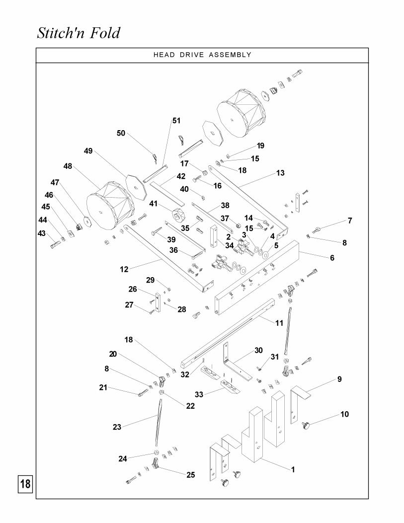
Stitch'n FoldHEAD DRIVE ASSEMBLY
2 3 45
9
11
34
32
31
15
25
24
26
17
20
22
28
44
1
51
6
7
10
12
13
14
8
16
18
19
15
21
23
18
27
8
29
33
30
3935
36
37
38
40
42
41
43
45
46
47
48
49
50

19
ISP Stitching & Bindery ProductsA D i v i s i o n O f S a m u e l S t r a p p i n g S y s t e m s
Index Part Part Name NumberNumber Number Required
1 CAAA2004V EZ Thread Stitcher Head 2CAAA2004U Conventional Stitcher Head 2
2 RBM1321A Knob Assy 23 CT32A Thin Washer 1/2 24 CB734 Lockwasher 1/2 25 CB198 Washer 1/2 26 RBM1011A Head Support Bar Assy 17 CB606 Hex Hd Scr 5/15-18 x 3/4 28 CB895 Lockwasher 5/16 69 RBM1315F Vacant Head Guard 310 CGG44B Knob Assy 311 RBM1013A Head Actuating Bar Assy 112 RBM1014F LH Actuating Bar Bracket 113 RBM1015F RH Actuating Bar Bracket 114 CB487A Hex Hd Scr 1/4-20 x 5/8 415 RBM1519F Lockwasher 1/4 616 CB487B Hex Hd Scr 1/4-20 x 1 217 RBM1017F Pivot Stud 218 CB718 Washer 1619 CB493 Nut 1/4-20 220 RBM1220F RH Rod End 221 CB110E Soc Hd Scr 5/16-24 x 1 1/4 422 CB418 RH Nut 5/16-24 223 RBM1037F Head Connecting Rod 224 RBM1262F LH Nut 5/16-24 225 RBM1221F LH Rod End 226 RBM1039F Head Drive Wear Strip 227 CB206B Flat Hd Scr 8-32 x 5/8 428 CB988A Lockwasheer #8 429 CB719 Nut 8-32 430 RBM1278F Ski Bracket 131 CG26F Button Hd Scr 1/4-20 x 1/2 232 CA9028A Roll Pin 1/8 x 11/16 433 RBM1342F Paper Ski 234 RBM1279F Roller Bar 135 CB51 Soc Hd Scr 1/4-20 x 3/4 236 CB764 Hex Hd Scr 1/4-20 x 1 1/2 137 CB860C Elastic Stop Nut 1/4-20 138 RBM1280F Roller Arm 239 RBM1361F Plastic Screw 1/4-20 x 1 1/2 140 RBM1362F Plastic Nut 1/4-20 141 CB1247A Roller 142 RBM1344F Foam Tire 143 CB314A Soc Hd Scr 3/8-16 x 3/4 244 RBM1520F Lockwasheer 3/8 245 CA46 Washer 246 CK180 Conical Spring 247 CA114A White Plastic Washer 248 415-0225 Spool of Stitching Wire 249 CA139 Spool Retainer 250 CK176 Hairpin 251 RBM1290F Wire Spool Stud 2

20
Stitch'n Fold MAIN TABLE ASSEMBLY
12
34
5
6
7 816
9
1011
13
12
12 3913
34
35
36
37
38
3332
31
14
40
15
25
24
26
26
42
41
17
14
18
1920
2122
23
27
28
30
29
43
44
45
4647
48
4955
2
2
2
50
5152
56
13
13
53
54
55

21
ISP Stitching & Bindery ProductsA D i v i s i o n O f S a m u e l S t r a p p i n g S y s t e m s
Index Part Part Name NumberNumber Number Required
1 RBM1004A Main Table 12 RBM1324F Pan Hd Scr 10-32 x 1/2 103 RBM1012F Clincher Bar 14 CB284A Dowel Pin 3/16 x 3/4 25 CB487A Hex Hd Scr 1/4-20 x 5/8 26 RBM1519F Lockwasher 1/4 27 CT9086X Clincher 58 CG26A Button Hd Scr 10-32 x 1/2 129 RBM1019F Pulley Bracket 110 RBM1020F Table Pulley 1
RBM1215F Table Pulley Bearing 211 RBM1021F Pulley Shaft 112 CB837B Retaining Ring 3/8 613 CG26 Button Hd Scr 10-32 x 3/8 1014 RBM1022F LH Bracket 215 RBM1023F RH Rear Bracket 116 RBM1024F RH Front Bracket 117 RBM1043F Tape Drive Shaft 118 RBM1128A Stop Carriage Assy 1
RBM1249F Plastic Bearing 219 RBM1049F Stop Platform 120 RBM1052F Switch Bracket 121 CB56M Soc Hd Scr 8-32 x 1/4 222 RBM1310F Microswitch 123 RBM1327F Rd Hd Scr 4-40 x 1/2 224 RBM1055F RH Front Guide Block 125 RBM1056F RH Rear Guide Block 126 CA9028A Roll Pin 1/8 x 11/16 327 RBM1057F RH Carriage Screw 128 RBM1058F LH Carriage Screw 129 RBM1059F Stop Spring 130 RBM1060F Spring Positioner 231 RBM1094F Table Belt 132 RBM1096F Table Drive Pulley 133 CB141 Set Scr 1/4-20 x 1/4 134 RBM1100F Idler Bracket 135 CB651 Soc Hd Cap Scr 10-32 x 1/2 236 RBM1101A Crowned Idler 1
RBM1264F Idler Bearing 137 RBM1340F Flat Idler 1
RBM1264F Idler Bearing 138 RBM1102F Idler Stud 239 CB1262 Washer #10 440 RBM1224F Knob 141 RBM1234F Solenoid 142 CE17 Washer 143 RBM1272F Solenoid Pivot Bracket 144 CB287A Rd Hd Scr 6-32 x 1/4 245 CK50 Lockwasheer #6 246 RBM1269F Sprocket 247 RBM1284F Chain 148 RBM1311F Split Collar 1
RBM1504F Spring 149 RBM1302F Belt Guard 150 RBM1309A Book Stop Assy 451 RBM1313F Gate Shaft 152 CB988A Lockwasher #8 253 CB651F Soc Hd Cap Scr 10-32 x 3/8 254 D31029F Washer #8 255 RBM1323F Pan Hd Scr 8-32 x 1/2 856 CG26N Button Hd Scr 8-32 x 3/8 2

22
Stitch'n Fold HEAD DRIVE SHAFT ASSEMBLY
1
2
34
5
7
8
910
11
12
32
13
14
15
16
17
18
19
20
21
22
23
24
26
2527
28
29
30
31
32
33
34
3535
3637
38
39
40
41
4220
43
2044
32
45
46
4847
4950
5152

23
ISP Stitching & Bindery ProductsA D i v i s i o n O f S a m u e l S t r a p p i n g S y s t e m s
Index Part Part Name NumberNumber Number Required
1 RBM1088F LH Side Guide 12 RBM1089F RH Side Guide 13 RBM1329F Flat Hd Scr 8-32 x 5/8 64 RBM1081F Spacer 25 RBM1080F Side Guide Bracket 2
CB56M Soc Hd Scr 8-32 x 1/4 47 RBM1343F Belt Bed 18 RBM1082F Guide Shaft Support 19 Washer #8 210 CB988A Lockwasher #8 211 CB719 Nut 8-32 212 CG26A Button Hd Scr 10-32 x 1/2 113 RBM1042F Head Drive Shaft 1
CB837E Retaining Ring 1RBM1510F Collar 1
14 RBM1078F Stationary Guide Shaft 115 RBM1229F Spring 116 RBM1079F Moveable Guide Shaft 117 CB835G Roll Pin 118 RBM1250F Plastic Bearing 119 RBM1038F Head Drive Crank 220 CB141 Set Screw 1/4-20 x 1/4 721 RBM1242F Woodruff Key 222 RBM1480A Bearing Assy 223 CB487A Hex Hd Scr 1/4-20 x 5/8 424 CB718 Washer 1/4 425 RBM1519F Lockwasher 1/4 426 CB493 Nut 1/4-20 427 RBM1047F Head Drive Pulley 128 RBM1254F Bearing 129 RBM1297F Knife Drive Pulley 130 RBM1227F Clutch 131 MF337 Soc Hd Scr 10-32 x 1 1/2 332 CB988 Lockwasher #10 433 RBM1125F Switch & Clutch Bracket 134 RBM1224F Pan Hd Scr 10-32 x 1/2 635 CB1262 Washer #10 336 RBM1265F Clutch Pin Block 137 CA9028A Roll Pin 238 CB651F Soc Hd Scr 10-32 x 3/8 139 RBM1225F Cam Microwitch 140 RBM1328F Rd Hd Scr 4-40 x 3/4 241 CG13 Nut 4-40 242 RBM1126F Switch Cam 143 RBM1092F Actuator Cam 144 RBM1091F LH Bracket 145 RBM1090F RH Bracket 146 RBM1086F Roller Stud 147 RBM1085F Roller 148 RBM1084F Actuator Bar 149 D22872F Set Scr 10-32 x 1/4 150 CB835P Roll Pin 151 RBM1087F Actuator Bar Extension 152 CG26 Button Hd Scr 10-32 x 3/8 1

24
Stitch'n Fold ROLLERS & KNIFE ASSEMBLY
1
2
35
7
8
10
14
Index Part Part Name NumberNumber Number Required
Index Part Part Name NumberNumber Number Required
15 RBM1064A Upper Folding Roll Assy 216 RBM1065A Lower Folding Roll Assy 217 CB2125 Nylon Washer 7/16 (3/4 O.D.) 3018 RBM1130A Bearing Block Assy 419 RBM1312F Split Collar 220 CA114A Teflon Washer 5/8 (1 1/2 O.D.) 221 RBM1123F Book Deflector 122 CG26A Button Hd Scr 10-32 x 1/2 423 CB278 Nut 10-32 424 CB988 Lockwasher #10 225 RBM1232F Lower Roll Spring 226 RBM1314F Upper Roll Spring 227 CG26C Button Hd Scr 10-32 x 3/4 4
CB278 Nut 10-32 8CB988 Lockwasher #10 4
1 RBM1505A Bearing Block Assy 22 RBM1010F Folder Retaining Plate 13 RBM1018F Spacer Table 14 RBM1025F Knife Guide Bracket 45 CG26N Button Hd Scr 8-32 x 3/8 126 CB988A Lockwasher #8 127 CB719 Nut 8-32 88 RBM1028F Knife Guide Rod 29 RBM1034A Knife Support Assy 110 RBM1249F Plastic Bearing 411 RBM1323F Pan Hd Scr 8-32 x 1/2 1012 RBM1324F Pan Hd Scr 10-32 x 1/2 1013 RBM1035F Folding Knife 1
CB651F Soc Hd Scr 10-32 x 3/8 414 RBM1063A Book Guide Assy 1
11
4
6
9
11
13
15
16
17
18
19
21 2223
24
26
20
12
25
27
12

25
ISP Stitching & Bindery ProductsA D i v i s i o n O f S a m u e l S t r a p p i n g S y s t e m s
KNIFE SHAFT ASSEMBLY
Index Part Part Name NumberNumber Number Required
Index Part Part Name NumberNumber Number Required
17 CB718 Washer 418 RBM1519F Lockwasher 1/4 419 CB493 Nut 1/4-20 420 RBM1041F Knife Drive Shaft 1
CB837E Retaining Ring 1RBM1510F Collar 1
21 RBM1227F Clutch 122 CA9028A Roll Pin 1/8 x 11/16 223 RBM1206A Pulley Assy 124 MF337 Soc Hd Scr 10-32 x 1 1/2 325 CB988 Lockwasher #10 326 RBM1300F Knife Clutch Bracket 127 RBM1324F Pan Hd Scr 10-32 x 1/2 2
1 RBM1036F Knife Connection Rod 22 RBM1040F Knife Drive Crank 23 CA9028A Roll Pin 1/8 x 11/16 24 RBM1222F RH Rod End 25 CB278 RH Nut 10-32 26 RBM1223F LH Rod End 27 RBM1263F LH Nut 10-32 210 CB651B Soc Hd Scr 10-32 x 3/4 411 CB988 Lockwasher #10 412 CB1262 Washer #10 813 CB278 Nut 10-32 215 RBM1480A Bearing Assy 216 CB487A Hex Hd Scr 1/4-20 x 5/8 4
1
23
5
10
11 4
6
13
15
16
17
18
19
21
23
24
12
7
22
20
25
26
27
22

26
Stitch'n Fold
1
23
5
8
10
11
4
6
13
15
16
17
18
19
21
24
12
7
14
9
23
20
BELTS & CHAINS ASSEMBLY
5
5
610
22
27
26
3
2514
928
2933
34
3132
30

27
ISP Stitching & Bindery ProductsA D i v i s i o n O f S a m u e l S t r a p p i n g S y s t e m s
Index Part Part Name NumberNumber Number Required
1 RBM1044A Idler Bracket Assy 42 RBM1045F Idler Bracket Stud 23 CB837B Retaining Ring 3/8 34 CG26 Button Hd Scr 10-32 x 3/8 15 CB988 Lockwasher #10 66 CG26C Button Hd Scr 10-32 x 3/4 57 RBM1292F Idler Spacer 18 D44958F Soc Hd Scr 1/4-20 x 2 1/2 19 RBM1519F Lockwasher 1/4 410 CB718 Washer 311 RBM1360F Idler Roll 112 RBM1294F Knife Idler Shaft 113 RBM1295F Idler Spacer 114 CB629B Soc Hd Scr 1/4-20 x 1 1/4 315 RBM1293F Stitcher Idler Shaft 116 RBM1291F Idler Roll 117 RBM1207F Reducer Pulley 10 Teeth 118 RBM1210F Timing Belt 1/2" Wide 119 RBM1211F Timing Belt 3/8" Wide 120 RBM1231F Idler Spring 421 CB278 Nut 10-32 822 CB606 Hex Hd Scr 5/16-18 x 3/4 123 CB895 Lockwasher 5/16 124 CB2125 Nylon Washer 7/16 (3/4 O.D.) 225 RBM1288F Sprocket Stud 126 CT32 Washer 127 RBM1286A Dual Sprocket Assy 128 RBM11289F Idler Stud 229 RBM1218A Idler Sprocket Assy 230 RBM1219F Long Chain 131 RBM1270F Short Chain 132 RBM1216F Folding Roll Sprocket 4
RBM1399F Set Screw 5/16-18 x 5/16 433 RBM1217F Drive Sprocket 134 CA9028A Roll Pin 1/8 x 11/16 135* RBM1432A 8T Sprocket (to Folding Roll) 136* RBM1430F 32T Sprocket (to Conveyor) 137* RBM1399F Set Screw 238* RBM1437A 12T/32T Double Sprocket 139* RBM1218A 12T Idler Sprocket 140* RBM1448F Chain 18.5" 141* RBM1449F Chain 17.0" 142* RBM1438F Shaft 243* CB328 Hex Hd Scr 3/8-16 x 5/8 244* CB179 Washer 245* RBM1520F Lockwasher 3/8 2 * Not shown

28
Stitch'n Fold SECONDARY TABLE ASSEMBLY
Index Part Part Name NumberNumber Number Required
Index Part Part Name NumberNumber Number Required
15 RBM1033F Rear Stop Support 116 RBM1031F Rear Stop Shaft 217 CB112 Rd Hd Scr 8-32 x 5/16 618 CB988A Lockwasher #8 419 RBM1311F Split Collar 220 RBM1052F Switch Bracket 121 RBM1310F Micro Switch 122 RBM1327F Rd Hd Scr 4-40 x 1/2 223 RBM1309A Stop Assy 424 RBM1133F Latch 125 CB70 Rd Hd Scr 8-32 x 3/16 226 CB719 Nut 8-32 227* RBM1381F Sensor Guard 128* RBM1324F Pan Hd Scr 10-32 x 1/2 4
1 RBM1129A Rear Stop Assy 12 RBM1249F Plastic Bearing 23 RBM1027F Guide Rod 24 RBM1005A Secondary Table 15 CG26N Button Hd Scr 8-32 x 3/8 26 RBM1032F Rear Stop Connecting Link 27 RBM1303F Stud Bracket 18 D30523F Soc Hd Cap Scr 8-32 x 1/2 49 RBM1304F Adjusting Stud 210 RBM1308F Wing Nut 10-32 211 CB278 Nut 10-32 312 CB988 Lockwasher #10 213 RBM1305F Spring 214 CB722A Set Scr 10-32 x 1/2 1
1
6
8
1817
19
13
14
22
3
21
11
20
4
15
25
12
10 16
9
7
11
25
26 23
24
17
* Not shown

29
ISP Stitching & Bindery ProductsA D i v i s i o n O f S a m u e l S t r a p p i n g S y s t e m s
DEL IVERY TABLE ASSEMBLY
Index Part Part Name NumberNumber Number Required
Index Part Part Name NumberNumber Number Required
18 CB2125 Nylon Washer 419* RBM1415F Booklet Stacker 120* RBM1438A Stud /Knob Assy 121* CT32A Thin Washer 1/2 122* CB734 Lockwasher 1/2 123* CB198 Washer 1/2 124* RBM1426F Wheel 225* RBM1412F Wheel Shaft 126* RBM1426F Wheel 227* CGG44 Thumb Screw 128* RBM1413F Wheel Rod 129* RBM1414F Cross Bracket 130* D37769F Roll Pin 1/8 x 1/2 131* CB837B Retaining Ring 3/8 232* CB837R Retaining Ring 1/2 433* RBM1380F Roller Discharge Guard 134* RBM1324F Pan Hd Scr 10-32 x 1/2 4
1 RBM1447F Delivery Table 12 RBM1069F Mounting Bracket 23 RBM1446A Delivery Tray 14 RBM1450F Drive Shaft 15 RBM1072F Drive Pulley 26 RBM1073F Idler Pulley 27 RBM1074F Idler Shaft 18 RBM1075F Bearing Block 29 RBM1425F Delivery Belt 210 RBM1214F Bronze Bearing 411 RBM1215F Bronze Bearing 212 RBM1258F Shaft Collar 213 CB278 Nut 10-32 414 CB988 Lockwasher #10 615 CB837B Retaining Ring 216 CG26A Button Hd Scr 10-32 x 1/2 617 D22872F Set Scr 10-32 x 1/4 2
1
6
8
13
14
3
4
15
2
5
12
10
16
9
7
11
17
18
* Not shown

30
Stitch'n FoldMAIN CONTROL PANEL
Index Part Part Name NumberNumber Number Required
Index Part Part Name NumberNumber Number Required
24* RBM1277F Interlock Switch (1LS, 2LS) 225* RBM1225F Micro Switch (3LS) 126* RBM1310F Micro Switch (4LS, 5LS) 227* RBM1317F Relay Bracket 128* RBM1324F Pan Hd Scr 10-32 x 1/2 229* CB2454 Power Relay (1CR) 130* CB650 Rd Hd Scr 6-32 x 1 431* CB720 Nut 6-32 432* RBM1416F Timer - Single Shot 133* RBM1417F Timer Socket 134* RBM1418F Timer Potentiometer 135* RBM1419F Potentiometer Knob 136* RBM1452F Gate Timer Decal 137* CB287E Rd Hd Scr 6-32 x 1/2 238* CB720 Nut 239* RBM1299F Transformer 140* RBM1323F Pan Hd Scr 8-32 x 1/2 241* RBM1298F Rectifier 142* RBM1324F Pan Hd Scr 10-32 x 1/2 143* RBM1234F Gate Solenoid 144* RBM1227F Clutch (Stitch, Fold) 245* RBM1443F Quencharc (QA) 1
1 RBM1335F Main Control Panel Decal 12 CG139 Pilot Light 13 CG137 Black Momentary Switch 24 CG136 Red Momentary Switch 15 RBM1445F Counter 16 CG138 Black Selector Switch 27 RBM1336F Auxiliary Control Panel Decal 18 CG135 Fuse Holder 29 RBM1267F Fuse 110 RBM1239F Fuse 111* RBM1353F Power Cord 112* RBM1266F Power Cord Bracket 113* RBM1323F Pan Hd Scr 8-32 x 1/2 214* CG218 Power Inlet 115* CB808 Flat Hd Scr 5-40 x 3/8 216* D27398F Elastic Stop Nut 217* RBM1240F Terminal Block 218* D32127F Rd Hd Scr 6-32 x 3/4 419* CB720 Nut 6-32 420* RBM1201F Motor 121* CB1070B Green Ground Screw 222* RBM1428F Rubber Grommet 523* RBM1429F Rubber Grommet 1
STITCHON OFFON OFF
COUNTS
ON OFF
FUSE
JOG
MOTOR
DC
MAIN
FUSE
AUXIL IARY CONTROL PANEL
1 6
8, 9
3 42 5
7
8, 10
3
6
* Not shown; see Schematic.

31
ISP Stitching & Bindery ProductsA D i v i s i o n O f S a m u e l S t r a p p i n g S y s t e m s
ELECTRICAL SCHEMATIC

32
Stitch'n Fold
USA:718 Marquette Street Racine, WI 534031-800-345-6641 1-414-632-5115Fax: 1-414-632-9240
FORM QF88 4/98
OUTSIDE USA:6843 Santa Fe Drive Hodgkins, IL 605251-708-482-9500Fax: 1-708-482-0274
ISP Stitching & Bindery ProductsA D i v i s i o n O f S a m u e l S t r a p p i n g S y s t e m s
ISP Stitching & Bindery ProductsA D i v i s i o n O f S a m u e l S t r a p p i n g S y s t e m s