ispe article
DESCRIPTION
ISPE Validation PracticeTRANSCRIPT
80 PHARMACEUTICAL ENGINEERING NOVEMBER/DECEMBER 2006
Validation Practice
Continued on page 82.
This case studypresents how asite validationpolicy wasdeveloped usinga modularvalidationapproach andincorporating thelatest FDAinitiatives, aswell as principlesfrom ISPE’sCommissioningand QualificationBaseline® Guide,GAMP® 4, andthe GAMP GoodPractice Guide:Validation ofLaboratoryComputerizedSystems.
Editor's Note:In August of2006, theHavant sitevalidationapproach wasformally honoredwith a WyethCorporate BestPractice Award.
Current Good Validation Practice
by Brian Collins and Kieran Sides
Introduction
Wyeth Pharmaceuticals approachedValidation in Partnership Ltd. withthe requirement to develop a sitevalidation policy that would
complement existing quality standards whilechanging the existing culture from one of multi-factory standards to one of more centralizedcontrol. The goal for this change was to presenta more unified approach to regulatory compli-ance and respond to a number of recent andpending industry initiatives. The new policywould need to satisfy the following:
• facilitate the continuity of the focused fac-tory management
• ensure 100% buy-in from department headsand the shop-floor
• be manageable, transparent and maintain-able
• add minimum overhead• fulfill all current regulatory requirements• comply with the principles of ISPE’s
Baseline® Guide on Commissioning andQualification1
• embrace all foreseeable industry and regu-latory trends
The ‘trends’ to be accommodated were thoseappearing in the latest guidance from the regu-latory agencies and industry advisory bodies,in particular:
• the FDA’s regulatory initiative: “Pharma-ceutical cGMPs for the 21st Century: ARisk-Based Approach”2
• the FDA’s guidance on Process AnalyticalTechnology (PAT)3
• rumors of a Quality Systems approach toinspections by the FDA4
It was also to later embrace:
• GAMP 45 and the GAMP Good PracticeGuide: Validation of Laboratory Computer-ized Systems6
More recently, there has been talk of minimizingthe amount of paperwork and repeat work gen-erated by validation departments by assigningmore work to vendors and by eliminating thenecessity for requalification and revalidation.
Although only needing to satisfy the re-quirements set down by the EMEA and PIC/S,corporate standards being issued from the USAwere imposing requirements specifically de-signed to satisfy the FDA as well.
OverviewUp to a few years ago, Wyeth’s history at its UKHavant site had been one of unparalleled com-mitment to the daily demands of its customerbase. The name became synonymous with theepitome in fast-tracking the installation andstart-up of new processes.
Inevitably, with this focus, against a back-ground of high activity, it was realized that thelevel of documentation to support such newintroductions would benefit from a more rigor-ous approach to meet the current expectationsof the regulatory agencies and the company’sown internal requirements.
The development of a sensible, workable,economic validation policy compliant with allcurrent and foreseeable initiatives, and provid-ing a springboard for the future would certainlybe difficult, but not too daunting. The introduc-tion of such a system while managing the chang-ing routines of a pharmaceutical business witha culture of decentralized management andcomprising the manufacturing and packing of adynamic portfolio of some 250 products would,unarguably, present something of a challenge.
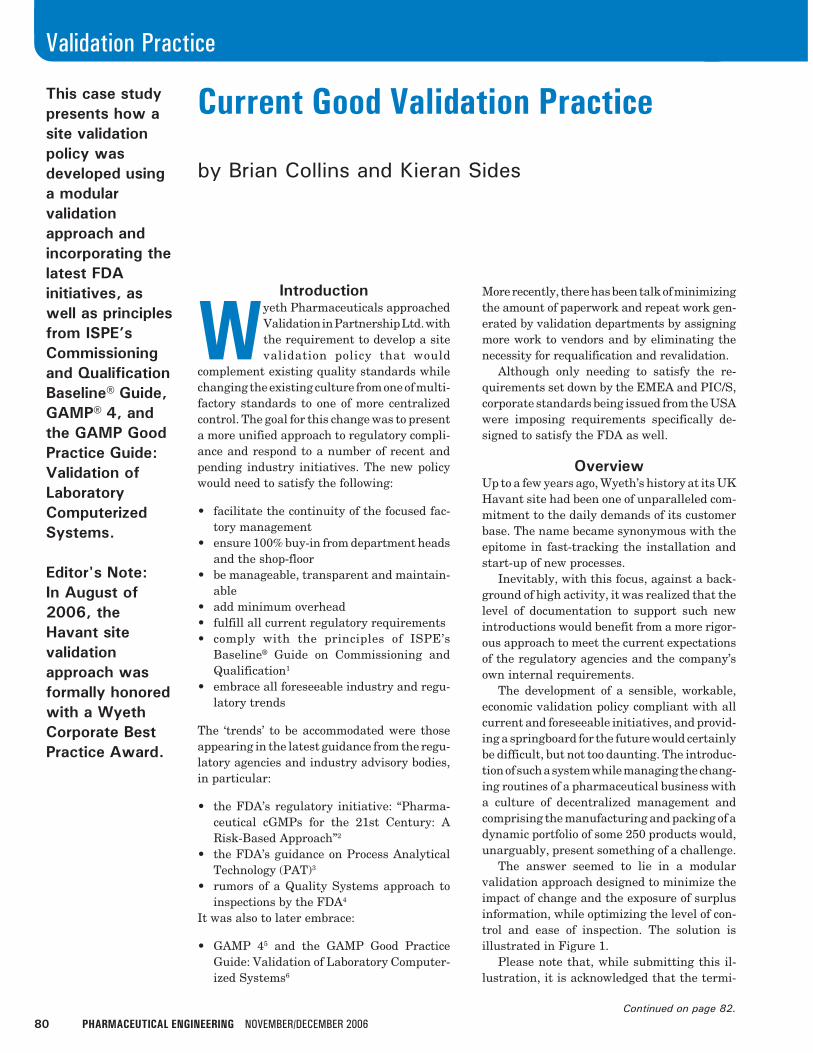
The answer seemed to lie in a modularvalidation approach designed to minimize theimpact of change and the exposure of surplusinformation, while optimizing the level of con-trol and ease of inspection. The solution isillustrated in Figure 1.
Please note that, while submitting this il-lustration, it is acknowledged that the termi-
82 PHARMACEUTICAL ENGINEERING NOVEMBER/DECEMBER 2006
Validation Practice
nology applied to the activities shown differs through theindustry. Similarly, it is appreciated that the division ofqualification/compliance activities is handled differently be-tween the various qualification stages from company tocompany. Therefore, the titles of the documents and activi-ties referred to in this article should not be assigned anyundue significance – it is their content and satisfactorycompletion in the correct sequence that matters.
The validation policy described is applied to all the hard-ware and software systems employed in a manufacturingprocess that are categorized as cGxP impacting, a categoryassigned to any system that can affect product quality. How-ever, there are a series of crucial activities that must beformally undertaken before any such assignation is possible.They are not considered part of the validation approach,because they are not specific regulatory requirements, butwithout them, all ensuing validation work would be unfounded.As such, they are referred to as validation foundations.
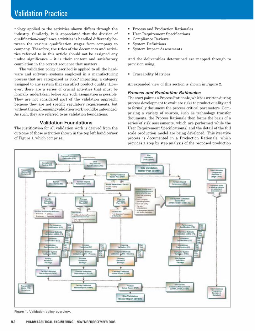
Validation FoundationsThe justification for all validation work is derived from theoutcome of those activities shown in the top left hand cornerof Figure 1, which comprise:
• Process and Production Rationales• User Requirement Specifications• Compliance Reviews• System Definitions• System Impact Assessments
And the deliverables determined are mapped through toprovision using:
• Traceability Matrices
An expanded view of this section is shown in Figure 2.
Process and Production RationalesThe start point is a Process Rationale, which is written duringprocess development to evaluate risks to product quality andto formally document the process critical parameters. Com-prising a variety of sources, such as technology transferdocuments, the Process Rationale then forms the basis of aseries of risk assessments, which are performed while theUser Requirement Specification(s) and the detail of the fullscale production model are being developed. This iterativeprocess is documented in a Production Rationale, whichprovides a step by step analysis of the proposed production
Figure 1. Validation policy overview.

NOVEMBER/DECEMBER 2006 PHARMACEUTICAL ENGINEERING 83
Validation Practice
process and a compilation of all parameters that may have animpact on the quality of the finished product. One ProductionRationale can be generated for each individual product or forseveral products of the same type. The hardware and soft-ware process systems are the obvious focus for this, but thereis a tendency to overlook other key aspects of the manufactur-ing process. Every step, from the arrival on site of rawmaterials and components, to the departure of finished prod-uct, needs to be considered. The way ingredients are speci-fied, procured, transported, off-loaded, handled, sampled,analyzed, stored, dispensed, and charged all can have anadverse effect on quality unless properly controlled, as can in-process sampling, handling, analysis, and subsequent fin-
ished product storage and despatch.Uninformed reactions to regulatory initiatives, such as
PAT, can be counterproductive, and in certain cases, result incatastrophic failure of the quality system. Without the funda-mental blueprint provided by the Process and ProductionRationales, additional in-process analytical steps installed todemonstrate compliance and control may inundate the manu-facturer with data providing more questions than answers. Inextreme cases, this supplementary data, which cannot beignored, has led beyond confusion and back to the drawingboard, as companies have been forced to admit they did notunderstand their processes well enough to control them.
Continued on page 84.
Figure 2. Validation foundations.
84 PHARMACEUTICAL ENGINEERING NOVEMBER/DECEMBER 2006
Validation Practice
The finally agreed Production Rationale, which shouldreference all supporting development reports, provides acomplete list of all product quality impacting parameters atevery step, and where possible, identifies all set-points andranges of tolerances. It is equally important that the non-critical parameters also are identified and the justificationfor their lack of criticality is documented. Simply omittingthese from the rationale begs the question of whether theywere even considered at all.
The rationale deliverable is a justification for every subse-quent process control measure, whether it be by facility,utility or equipment qualification, automation validation,calibration, in-process monitoring, Standard Operating Pro-cedure (SOP), or training. All static and dynamic attributesof the process are included. A parameter such as equipmentproduct contact parts is assigned to Installation Qualifica-tion for verification, whereas the standing time for an off-loaded drum of material becomes the subject of an SOP. Thecharging of an ingredient into a mixing vessel, if a manualoperation, is controlled by approved SOP, training, and cali-brated time piece, where appropriate. Dynamics such asmixing speed are covered by Operation Qualification. There-after, they are monitored and trended, either by a suitablyindependently validated and maintained automated systemor by manual measurements at specified intervals by quali-fied individuals trained in approved SOPs and using cali-brated test equipment.
If another product of similar type is later introduced formanufacture using the same process, the Production Ratio-nale is revisited to incorporate the new product and make anynecessary adjustments to the operating ranges of the processparameters.
As with all the documents referred to in this article, onceapproved, Production Rationales must be governed by thesite change control system. System Impact Assessments willrely on these rationales to provide the parameters for quali-fication checking and testing, and where applicable, theranges or operational limits.
User Requirement SpecificationsThe importance of the role played by User RequirementSpecifications (URSs) cannot be stressed enough. They pro-vide a home for all the known requirements of all stakehold-ers and are generated as a precursor to procurement of allfacilities, utilities, equipment, and operating systems. Themodular approach to the validation documentation systemalso is favored here with non-detailed Project URSs providingthe master control over more detailed System URSs. Com-piled as tender documents, they provide all the informationnecessary for prospective vendors to satisfy all the hardware,software, and documentation requirements of the Quality,Production, Engineering, and Maintenance departments.The URS covers not only the current requirements of GMP,GAMP (other GxP compliance issues, as appropriate), theregistered process(es), and corporate standards, but is ex-panded to become a receptacle for all required deliverables.
There may be several ways in which to satisfy a particularbusiness need so the URS is not unnecessarily restrictive.Wherever possible, designers are permitted to offer the mostcost-effective and compliant solutions. In cases where thereis scope for interpretation, URSs are accepted as iterative,becoming more prescriptive as the design is developed.
There are numerous URS formats in use throughout theindustry, and there are good and bad elements in all. Theformat adopted for the Havant site was developed with anautomated documentation process in mind, which is describedfurther on. The URS groups the requirements according to thephases of the project life cycle during which they are to bedelivered with separate sections for the design, vendor assess-ment, construction, factory testing, installation, commission-ing, operation, training and maintenance phases of the project.Each individual requirement is given a unique identifier anda suffix, the suffix denoting the origin (cGMP, GAMP, Process,HSE, etc.), e.g., “5.3 Certification exists to demonstrate that allcontact part materials correspond to the approved design re-quirements [cGMP].” This would appear in the list of items tobe verified at the Installation Phase. Each requirement iswritten as a clear and unambiguous deliverable that is liftedverbatim into a subsequent document as a predeterminedacceptance criterion. This eliminates any later confusion aris-ing from a misinterpretation of the requirement.
A URS is generally subject to constant development priorto procurement, but it also can be affected by changes agreedthroughout the design and construction stages. With this in
NOVEMBER/DECEMBER 2006 PHARMACEUTICAL ENGINEERING 85
Validation Practice
mind, the URS has an integrated change control mechanismto facilitate amendment. Even after the installation of asystem has been qualified, there may be changes necessi-tated by unforeseen circumstances that will impact the URS.As all validation protocols import their acceptance criteriafrom the URS, the Site Change Control System ensures thesemodifications are captured and it is updated.
Compliance ReviewsA Request for Proposal is issued to prospective vendors andthe proposed designs submitted are checked for compliancewith the user requirements. This is the role played by theCompliance Review. It performs the same function as theEnhanced Design Review in the ISPE Baseline® Guide onCommissioning and Qualification,7 and what some refer to asDesign Qualification. The EMEA suggests this ‘could’ be thefirst stage of validation7 and intimate that the compliance ofthe design with cGMP should be documented.8 The FDA, onthe other hand, does not require a formal review at designstage to verify regulatory compliance, which is contradictoryto the very essence of the meaning of validation.
The reason we validate is because we cannot test qualityinto the end product. Unfortunately, the regulators seem tohave diluted this message. If we follow the letter of the law,qualification is not required until an installation is complete,which is way too late for any non-compliances to be rectified.In the real world, where projects are generally behind sched-
ule, the discovery during Installation Qualification that thedesign was not all it should be, is far more likely to lead to acompromise in standards than the necessary alterations. Forpure economy alone, it makes more sense to identify anderadicate potential shortcomings on the drawing board thanactual faults on site.
Each individual user requirement is verified as a deliver-able of the proposed design by recording the precise locationwithin the design package where the vendor’s intention tocomply is documented. Only then can an order be placed.
It is recognized that design development is the domain ofthe vendor so the Site Change Control System is not invokeduntil the commencement of Installation Qualification. Pro-spective vendors are audited to verify that adequate changecontrols will be employed to safeguard the user requirementsas the design is developed and components are procured.
Although performed at proposal submission stage, theCompliance Review incorporates a similar means of changecontrol to the URS, ensuring that all subsequent changes to theuser requirements are formally accepted by the vendor. Auditsof the two change control systems at intervals prior to thecommencement of Installation Qualification will confirm thevendor’s sustained commitment to compliance with the URS.
System DefinitionsA System Impact Assessment will determine whether or notvalidation is needed, but before this can occur, the full extent
Continued on page 86.
86 PHARMACEUTICAL ENGINEERING NOVEMBER/DECEMBER 2006
Validation Practice
of the system has to be known. A System Definition documentnot only identifies the physical boundaries of the system, butalso provides a complete description of the static and dynamicattributes of the system. It constitutes a key ingredient of themodular approach to validation, as the descriptions in valida-tion plans and protocols can be minimized, supported by asimple cross-reference. For something as complex as an auto-mated Clean-in-Place system with numerous interfaces withother systems, the finished document would contain a sche-matic diagram, marked up to identify the start and finishpoints, a detailed specification of the installation and function-ality, and an index identifying the references, versions, andlocations of all other pertinent documentation, back-up soft-ware programs, etc. For simpler, stand-alone systems such asa refridgerator or a pH meter, a vendor’s brochure may suffice.
System Impact AssessmentsWith the system fully defined, the next risk assessment isperformed, which is the System Impact Assessment (SIA).This is when the decision is made whether or not the systemneeds to be qualified. The SIA is referred to as the ImpactAssessment in ISPE’s Commissioning and QualificationBaseline® Guide.9
The criteria provided by ISPE and the Production Rationaleare used to determine if Good Engineering Practice (GEP)10
standards alone will suffice or if they need to be supplementedby the appropriate validation phases. It can be tempting toease up on the documentation standards for systems exemptfrom qualification, but one day the use of a system may bechanged such that it can impact on product quality and needsto be qualified. It may not be possible to qualify a systemlacking the necessary supporting documentation.
Every SIA includes a matrix, which maps the system/systems covered against its/their critical parameters, asdefined by the relevant Production Rationale(s). The SIA isrevisited each time there is an amendment to a ProductionRationale, this revisit being prompted by the Site ChangeControl System and its inbuilt risk assessment. For example,
if the scope of an existing manufacturing process is extendedto cover the introduction of an additional product, any changesrequired to the operational limits of any of the processparameters will be passed on to the SIA. In response to therevised SIA, the duly amended Traceability Matrix willproject where an evaluation is required of the impact on theexisting qualification package.
Traceability MatricesTraceability Matrices are now in common use, plotting theprojected delivery of every single user requirement to ensurenothing is overlooked. Most companies use them prospec-tively to define precisely where each requirement will beverified as satisfied. But they also can be used retrospectivelyto identify exactly where the fulfillment of a requirement isactually documented. They are used mainly to demonstratecontrol of the current GxP requirements, but, if the URS isproperly structured, there is no reason why individual matri-ces should not be compiled for all other requirements, such ashealth, safety and environment, or corporate standards.
If more than one Traceability Matrix is generated, therealso should be a master overseeing them, which, retrospec-tively, would verify that all individual matrices had beenbrought to a satisfactory conclusion.
Validation PolicyThe Site Validation Policy presents the complete approach tovalidation across the site.
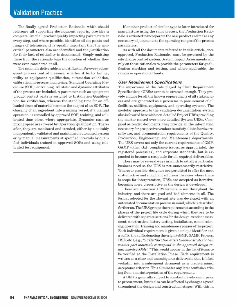
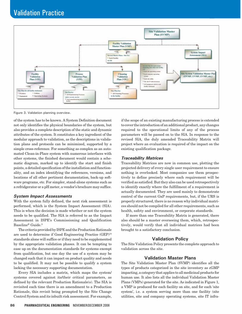
Validation Master PlansThe Site Validation Master Plan (SVMP) identifies all thetypes of products categorized in the site inventory as cGMPimpacting, a category that applies to all medicinal products forhuman use. It also lists all the individual Validation MasterPlans (VMPs) generated for the site. As indicated in Figure 1,a VMP is produced for each facility on site, and for each ‘sitesystem’, i.e. a system serving more than one facility (siteutilities, site and company operating systems, site IT infra-
Figure 3. Validation planning overview.
NOVEMBER/DECEMBER 2006 PHARMACEUTICAL ENGINEERING 87
Validation Practice
structure, and equipment systems that are not facility-dedi-cated). The SVMP then identifies, for each product, whichVMPs are impacted during any stage of its manufacturingprocess. An expanded view of this section is shown in Figure 3.
Validation PlansEach Facility VMP introduces three types of Validation Plans(VPs); one for the facility, one for the manufacturing pro-cesses and products accommodated therein, and one for theassociated cleaning processes. The modular approach pre-sented here would be less beneficial to a single productfacility for which it may be feasible to omit the VPs byincorporating their contents into the Facility VMP.
System descriptions in the VMPs and VPs need be nothingmore than cross-references to the System Definition docu-ments. This enables any change, other than one impacting acritical parameter, to be accommodated and documentedwithout the need for a revision to the plan.
The Facility VP covers all the facility-dedicated systems,which include the premises (the facility itself and the variousrooms) and all the equipment, utilities, and operating sys-tems located within the facility. It acknowledges the ‘sitesystems’ serving the facility, but simply cross references totheir VMPs for any detail, and it makes no mention ofmanufacturing or cleaning processes at all. The plan thenintroduces the phases of validation it controls and containsthe traditional matrix plotting systems against their as-
signed qualification and/or validation phases. The phasescovered by a Facility VP are the same as those of a ‘sitesystem’ VMP, as can be seen in Figure 1.
The Process VP details the manufacturing process for eachproduct produced and/or packed in the facility. It groups theproducts in families according to their production or packingprocesses and identifies both the facility-dedicated systemsand the ‘site systems’ impacting these processes. If a facilityis subject to an ever-changing production schedule, it may beappropriate to modularize the approach further and generateseparate Process VPs for individual manufacturing or pack-ing processes to minimize revisions to the plan.
Although identifying all the hardware and software systemsinvolved in each process, the Process VP merely directs thereader to the Facility VP or the ‘site system’ VMP for furtherdetails. It then provides an overview of the validation phases itcovers, i.e., Process Validation (PV) and Analytical MethodsValidation (AMV), and a matrix showing the assignment ofthese phases to the products and processes included in the plan.
The Cleaning VP details all possible permutations of prod-uct family campaigns for each of the production or packingprocesses operated within the facility and considers all oppor-tunities of potential cross-contamination, including those in-volving products not categorized as cGMP impacting. The planidentifies all the equipment to be cleaned and all the systemsto be used in the cleaning processes, the facility-dedicatedsystems, and the ‘site systems.’ However, it simply points to
Continued on page 88.
88 PHARMACEUTICAL ENGINEERING NOVEMBER/DECEMBER 2006
Validation Practice
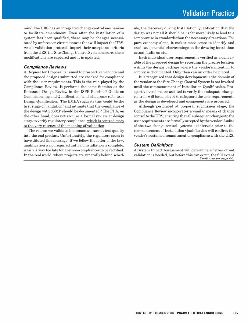
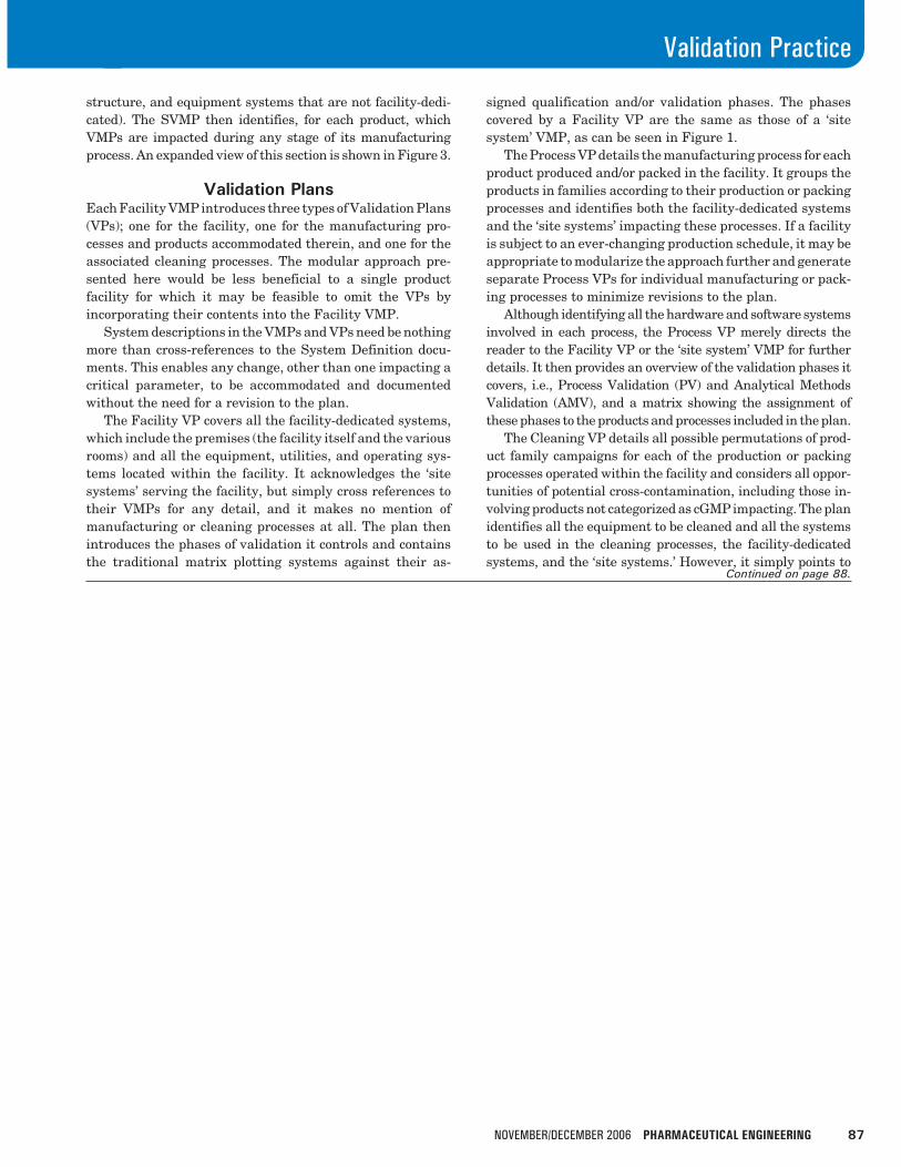
Figure 4. Qualification documentation pverview.
the Facility VP for further details of the facility-dedicatedsystems and to the appropriate VMP for each ‘site system.’ Italso contains an introduction to the Cleaning Validation (CV)and Analytical Methods Validation (AMV) phases covered anda matrix assigning these phases against the various processes.
This modular validation planning ensures a minimizationof the impact of any site changes, such as the installation ofan additional compressor to increase the capacity of the SiteCompressed Air System. Even though the system may servenumerous facilities and processes across the site, the onlyplan requiring a revisit would be the Site Compressed AirSystem VMP. Similarly, the introduction of a new product,the operational limits of which are within those alreadytested for its product family, would require nothing morethan an inventory update. There would be no need to revisitthe Cleaning VP, Process VP, IQ, or OQ, and there would beno urgency to produce the three consecutive replicate batchesrequired to validate the process; they would simply fall in linewith the production schedule.
Validation ProgramAnnex 15 to the EU Guide11 specifies that a VMP shouldcontain data on “planning and scheduling.” True to the modu-larity of the approach, the validation program is generated andmaintained as a separate document with recognition providedby a simple cross reference from the SVMP. With a productportfolio like the one at Havant, the production schedule wouldotherwise render the upkeep of the SVMP impossible. A formalvalidation program should indicate the appropriate sequenceof all validation activities covered by the VMPs and VPs, butit should always have plenty of slack built in as there is nothingmore ridiculous than deviations being raised during a valida-tion project simply because timelines have not been met. Thegeneration of such deviations is completely pointless as they
cannot possibly be resolved, merely accepted.The program is not just a regulatory requirement, but it is
also an essential validation control document. As such, alladditions and removals are subjected to the Site ChangeControl System.
An evolutionary approach to the development of detailwithin the validation program as the life cycle develops isparticularly important for a new or expanding site. Manyprojects have ground to a halt or been forced to proceed withunapproved or unrepresentative plans as a result of trying todefine all the detail at the outset, when such detail is simplynot available. This is one of the primary factors in modularizingthe validation package in terms of VMPs and VPs, such thatthe level of detail presented in each is appropriate to the levelof knowledge available at the time it is generated. A similarend point could be achieved through the continued revision ofa single plan, from an initial high level approach, as repre-sented by our Site VMP, to a detailed approach, as repre-sented by Site System VMPs and Facility, Process, andCleaning VPs. However, the final provision of such a plandoes not lend itself to change, as even minor site modifica-tions would necessitate the continuous revision and re-issueof what would be an extremely bulky text for approval. It issimple enough to provide a validation package to support anew site or facility, but considerably more difficult to producea package that is easily maintainable over time.
Protocols and ReportsAll protocols and reports, whether for a Compliance Review,Installation Qualification, or Process Validation follow thesame modular pattern as indicated by Figure 4. Protocols areconstructed such that each of the series of pre-requisites,checks and tests contained therein has its own objective,methodology, and acceptance criteria section. Each objective
NOVEMBER/DECEMBER 2006 PHARMACEUTICAL ENGINEERING 89
Validation Practice
Continued on page 90.
is to provide documented evidence that a pre-requisite hasbeen satisfied or that a check or test has been successfullycompleted. The methodology sections explain only the intentand not the step by step detail of the execution procedure.This is provided elsewhere, on stand-alone record sheets. Thereasons for this are several. For a complex OQ test, the headsof department nominated to approve a protocol are unlikelyto be sufficiently acquainted with a system to be able to agreea detailed test procedure, but they should be comfortablyqualified to approve the intent of the test.
There also may be various ways to execute a test. Forinstance, a test to verify the satisfactory operation of a highlevel switch for a purified water system storage tank can beincluded in the protocol with only high level detail of how thistest will be conducted. For example, it will be important thata suitable quality of water is used and that the high levelswitch is activated when the water in the tank reaches apredefined level (with tolerance). However, it may not benecessary to charge the water from the associated purifiedwater generation system or within a particular time period.The skill is to document the critical elements of the testmethodology at a high level in the protocol, and to clearlydefine the supporting acceptance criteria. The detail of thevalve sequences, interlocks, etc., required to safely realize thetest on the plant can be derived following approval of theprotocol as more detail of the installation and commissioningstatus of the facility becomes available.
The most appropriate way of testing might not have beendecided, but this is no reason to delay what can be a lengthyprotocol review and approval process. Whatever method iseventually selected, the test acceptance criteria will be thesame. When finally decided, the record sheet will prescribethe specific qualification steps to be followed in performingthe test. The finished record sheet is then submitted to themost technically competent person to review the detail beforeapproving it for execution. There is no need for a Qualitydepartment approval of the record sheet, as all the protocolapprovers will see the completed sheet when reviewing andapproving the report.
Separating the detail from the protocol in this way has anumber of advantages, including reduced review and ap-proval times. The most significant time (and cost) savings canbe realized in respect to tests which protocol reviewers deemunnecessary or approaches with which they fundamentallydisagree. In a traditional system, by this stage the protocolauthor would have already wasted valuable time trying towrite a detailed test script, which is now redundant. In themodel proposed here, such wastage is minimized.
When all the protocol record sheets have been executed andcompleted, a report is written to summarize their results. ASummary Report enables the next stage of validation to com-mence, even though there are outstanding minor deviations,and a Final Report is generated on their satisfactory resolution.
90 PHARMACEUTICAL ENGINEERING NOVEMBER/DECEMBER 2006
Validation Practice
With the current emphasis on Quality Risk Management(QRM),12 it was wholly appropriate to embrace the concept ofits scientific, risk-based framework within the validationapproach. Although the message of QRM, and particularlyPAT, is often focused on in-process control and analysis, theprinciples should be spread to cover any part of the processwhere enhancements can increase product quality.
Since 1987, the FDA’s Guideline on General Principles ofProcess Validation13 has stated “Process validation is estab-lishing documented evidence which provides a high degree ofassurance that a specific process will consistently produce aproduct meeting its pre-determined specifications and qual-ity characteristics.” It was decided that QRM should now beapplied, not just to the consistent production of product, butalso to the production of the documented evidence. To thisend, the entire documentation process illustrated in Figure 1was automated to minimize the risk of human error, an everpresent feature of paperwork systems.
Automated Document TemplatesMicrosoft Word templates were developed initially for all thevalidation documents to instantly generate Validation Mas-
ter Plans and Reports, Validation Plans and Reports, Instal-lation, Operation, and Performance Qualification (IQ, OQ,and PQ) Protocols, Computer System, Cleaning Validation,and Process Validation (CSV, CV, and PV) Protocols, andRecord Sheets and Reports.
The scope was then broadened to provide automatedtemplates for the validation foundation documents, such asUser Requirement Specifications, Traceability Matrices, Sys-tem Impact Assessments, and Compliance Reviews. Finally,Computer System Validation (CSV) support documents, suchas Quality Plans, Risk Assessments, Design Reviews, andConfiguration Reviews also were automated, providing tem-plates for both GAMP’s System Development and SystemImplementation Life Cycles. These refer to the requirementsspecified in GAMP 4 Guide to Validation of AutomatedSystems and the more recent GAMP Good Practice Guide:Validation of Laboratory Computerized Systems respectively.
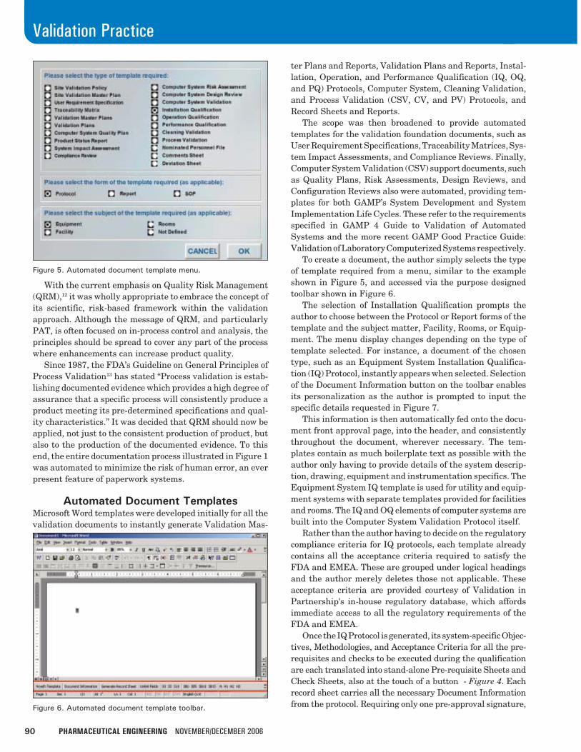
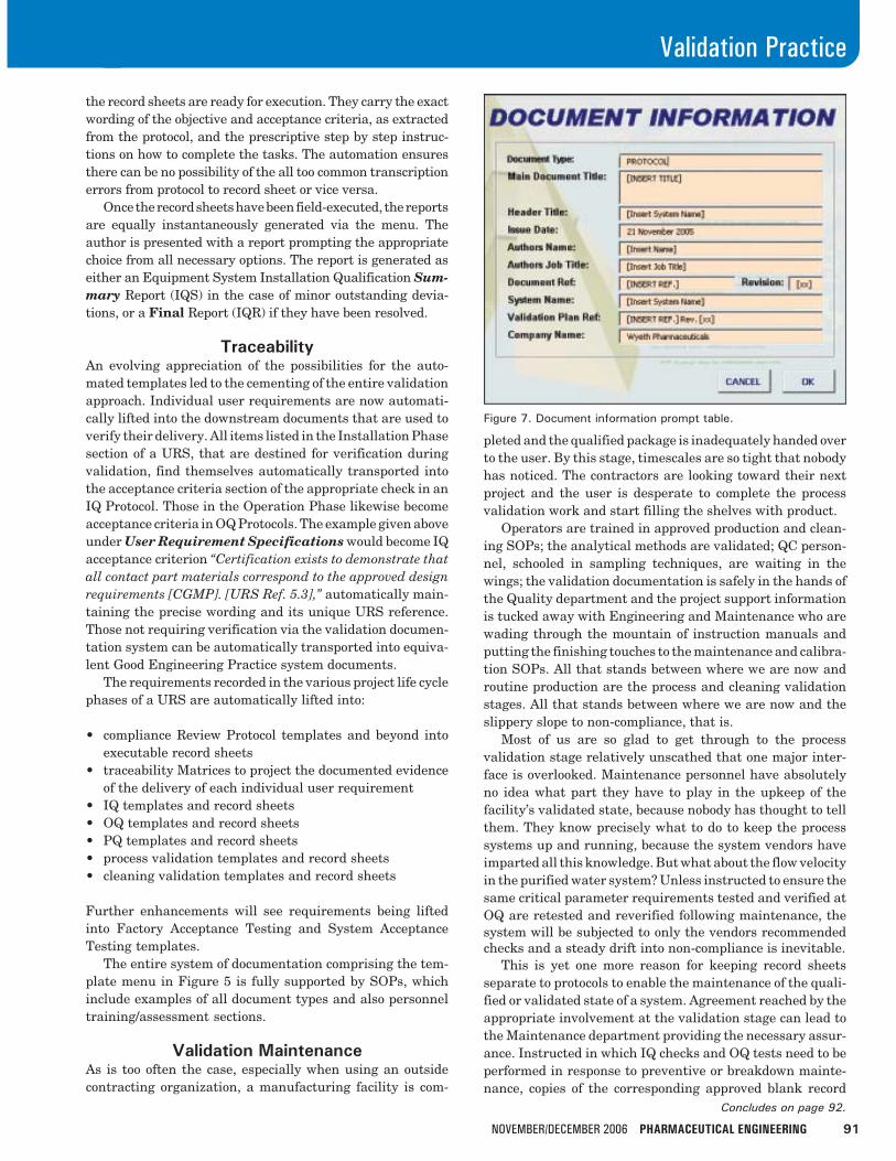
To create a document, the author simply selects the typeof template required from a menu, similar to the exampleshown in Figure 5, and accessed via the purpose designedtoolbar shown in Figure 6.
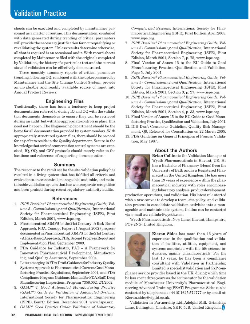
The selection of Installation Qualification prompts theauthor to choose between the Protocol or Report forms of thetemplate and the subject matter, Facility, Rooms, or Equip-ment. The menu display changes depending on the type oftemplate selected. For instance, a document of the chosentype, such as an Equipment System Installation Qualifica-tion (IQ) Protocol, instantly appears when selected. Selectionof the Document Information button on the toolbar enablesits personalization as the author is prompted to input thespecific details requested in Figure 7.
This information is then automatically fed onto the docu-ment front approval page, into the header, and consistentlythroughout the document, wherever necessary. The tem-plates contain as much boilerplate text as possible with theauthor only having to provide details of the system descrip-tion, drawing, equipment and instrumentation specifics. TheEquipment System IQ template is used for utility and equip-ment systems with separate templates provided for facilitiesand rooms. The IQ and OQ elements of computer systems arebuilt into the Computer System Validation Protocol itself.
Rather than the author having to decide on the regulatorycompliance criteria for IQ protocols, each template alreadycontains all the acceptance criteria required to satisfy theFDA and EMEA. These are grouped under logical headingsand the author merely deletes those not applicable. Theseacceptance criteria are provided courtesy of Validation inPartnership's in-house regulatory database, which affordsimmediate access to all the regulatory requirements of theFDA and EMEA.
Once the IQ Protocol is generated, its system-specific Objec-tives, Methodologies, and Acceptance Criteria for all the pre-requisites and checks to be executed during the qualificationare each translated into stand-alone Pre-requisite Sheets andCheck Sheets, also at the touch of a button - Figure 4. Eachrecord sheet carries all the necessary Document Informationfrom the protocol. Requiring only one pre-approval signature,
Figure 5. Automated document template menu.
Figure 6. Automated document template toolbar.
NOVEMBER/DECEMBER 2006 PHARMACEUTICAL ENGINEERING 91
Validation Practice
Concludes on page 92.
the record sheets are ready for execution. They carry the exactwording of the objective and acceptance criteria, as extractedfrom the protocol, and the prescriptive step by step instruc-tions on how to complete the tasks. The automation ensuresthere can be no possibility of the all too common transcriptionerrors from protocol to record sheet or vice versa.
Once the record sheets have been field-executed, the reportsare equally instantaneously generated via the menu. Theauthor is presented with a report prompting the appropriatechoice from all necessary options. The report is generated aseither an Equipment System Installation Qualification Sum-mary Report (IQS) in the case of minor outstanding devia-tions, or a Final Report (IQR) if they have been resolved.
TraceabilityAn evolving appreciation of the possibilities for the auto-mated templates led to the cementing of the entire validationapproach. Individual user requirements are now automati-cally lifted into the downstream documents that are used toverify their delivery. All items listed in the Installation Phasesection of a URS, that are destined for verification duringvalidation, find themselves automatically transported intothe acceptance criteria section of the appropriate check in anIQ Protocol. Those in the Operation Phase likewise becomeacceptance criteria in OQ Protocols. The example given aboveunder User Requirement Specifications would become IQacceptance criterion “Certification exists to demonstrate thatall contact part materials correspond to the approved designrequirements [CGMP]. [URS Ref. 5.3],” automatically main-taining the precise wording and its unique URS reference.Those not requiring verification via the validation documen-tation system can be automatically transported into equiva-lent Good Engineering Practice system documents.
The requirements recorded in the various project life cyclephases of a URS are automatically lifted into:
• compliance Review Protocol templates and beyond intoexecutable record sheets
• traceability Matrices to project the documented evidenceof the delivery of each individual user requirement
• IQ templates and record sheets• OQ templates and record sheets• PQ templates and record sheets• process validation templates and record sheets• cleaning validation templates and record sheets
Further enhancements will see requirements being liftedinto Factory Acceptance Testing and System AcceptanceTesting templates.
The entire system of documentation comprising the tem-plate menu in Figure 5 is fully supported by SOPs, whichinclude examples of all document types and also personneltraining/assessment sections.
Validation MaintenanceAs is too often the case, especially when using an outsidecontracting organization, a manufacturing facility is com-
pleted and the qualified package is inadequately handed overto the user. By this stage, timescales are so tight that nobodyhas noticed. The contractors are looking toward their nextproject and the user is desperate to complete the processvalidation work and start filling the shelves with product.
Operators are trained in approved production and clean-ing SOPs; the analytical methods are validated; QC person-nel, schooled in sampling techniques, are waiting in thewings; the validation documentation is safely in the hands ofthe Quality department and the project support informationis tucked away with Engineering and Maintenance who arewading through the mountain of instruction manuals andputting the finishing touches to the maintenance and calibra-tion SOPs. All that stands between where we are now androutine production are the process and cleaning validationstages. All that stands between where we are now and theslippery slope to non-compliance, that is.
Most of us are so glad to get through to the processvalidation stage relatively unscathed that one major inter-face is overlooked. Maintenance personnel have absolutelyno idea what part they have to play in the upkeep of thefacility’s validated state, because nobody has thought to tellthem. They know precisely what to do to keep the processsystems up and running, because the system vendors haveimparted all this knowledge. But what about the flow velocityin the purified water system? Unless instructed to ensure thesame critical parameter requirements tested and verified atOQ are retested and reverified following maintenance, thesystem will be subjected to only the vendors recommendedchecks and a steady drift into non-compliance is inevitable.
This is yet one more reason for keeping record sheetsseparate to protocols to enable the maintenance of the quali-fied or validated state of a system. Agreement reached by theappropriate involvement at the validation stage can lead tothe Maintenance department providing the necessary assur-ance. Instructed in which IQ checks and OQ tests need to beperformed in response to preventive or breakdown mainte-nance, copies of the corresponding approved blank record
Figure 7. Document information prompt table.
92 PHARMACEUTICAL ENGINEERING NOVEMBER/DECEMBER 2006
Validation Practice
sheets can be executed and completed by maintenance per-sonnel as a matter of routine. This documentation, combinedwith data generated during trending of critical parameterswill provide the necessary justification for not requalifying orrevalidating the system. Unless results determine otherwise,all that is required is an occasional audit. With record sheetscompleted by Maintenance filed with the originals completedby Validation, the history of a particular test and the currentstate of validation can be effectively demonstrated.
Three monthly summary reports of critical parametertrending following OQ, combined with the upkeep assured byMaintenance and the Site Change Control System, providean invaluable and readily available source of input intoAnnual Product Reviews.
Engineering FilesTraditionally, there has been a tendency to keep projectdocumentation referred to during IQ and OQ with the valida-tion documents themselves to ensure they can be retrievedduring an audit, but with the appropriate controls in place, thisneed not happen. The Engineering department should be thehome for all documentation provided by system vendors. Withappropriately structured system files, there should be no needfor any of it to reside in the Quality department. Secure in theknowledge that strict documentation control systems are exer-cised, IQ, OQ, and CSV protocols should merely refer to thelocations and references of supporting documentation.
SummaryThe response to the remit set for the site validation policy hasresulted in a living system that has fulfilled all criteria andevolved into an economical, manageable, auditable, and main-tainable validation system that has won corporate recognitionand been praised during recent regulatory authority audits.
References1. ISPE Baseline® Pharmaceutical Engineering Guide, Vol-
ume 5 - Commissioning and Qualification, InternationalSociety for Pharmaceutical Engineering (ISPE), FirstEdition, March 2001, www.ispe.org.
2. Pharmaceutical cGMPS for the 21st Century - A Risk-BasedApproach, FDA, Concept Paper, 21 August 2002 (progressdocumented in Pharmaceutical cGMPS for the 21st Century- A Risk-Based Approach, FDA, Second Progress Report andImplementation Plan, September 2003.
3. FDA Guidance for Industry, PAT – A Framework forInnovative Pharmaceutical Development, Manufactur-ing, and Quality Assurance, September 2004.
4. Later emerging in FDA Draft Guidance for Industry QualitySystems Approach to Pharmaceutical Current Good Manu-facturing Practice Regulations, September 2004, and FDACompliance Program Guidance Manual for FDA Staff, DrugManufacturing Inspections, Program 7356.002, 2/1/2002.
5. GAMP® 4, Good Automated Manufacturing Practice(GAMP®) Guide for Validation of Automated Systems,International Society for Pharmaceutical Engineering(ISPE), Fourth Edition, December 2001, www.ispe.org.
6. GAMP® Good Practice Guide: Validation of Laboratory
Computerized Systems, International Society for Phar-maceutical Engineering (ISPE), First Edition, April 2005,www.ispe.org.
7. ISPE Baseline® Pharmaceutical Engineering Guide, Vol-ume 5 - Commissioning and Qualification, InternationalSociety for Pharmaceutical Engineering (ISPE), FirstEdition, March 2001, Section 7, p. 75, www.ispe.org.
8. Final Version of Annex 15 to the EU Guide to GoodManufacturing Practice, Qualification and Validation,Page 5, July 2001.
9. ISPE Baseline® Pharmaceutical Engineering Guide, Vol-ume 5 - Commissioning and Qualification, InternationalSociety for Pharmaceutical Engineering (ISPE), FirstEdition, March 2001, Section 3, p. 27, www.ispe.org.
10. ISPE Baseline® Pharmaceutical Engineering Guide, Vol-ume 5 - Commissioning and Qualification, InternationalSociety for Pharmaceutical Engineering (ISPE), FirstEdition, March 2001, Section 4, p. 33, www.ispe.org.
11. Final Version of Annex 15 to the EU Guide to Good Manu-facturing Practice, Qualification and Validation, July 2001.
12. ICH Draft Consensus Guideline, Quality Risk Manage-ment, Q9, Released for Consultation on 22 March 2005.
13. FDA Guideline on General Principles of Process Valida-tion, May 1987.
About the AuthorsBrian Collins is the Validation Manager atWyeth Pharmaceuticals in Havant, UK. Hehas a Bachelor of Pharmacy (Hons) from theUniversity of Bath and is a Registered Phar-macist in the United Kingdom. He has morethan 19 years of experience within the phar-maceutical industry with roles encompass-ing laboratory analysis, product development,
production operations, and validation. His latest role startedwith a new canvas to develop a team, site policy, and valida-tion process to consolidate validation activities into a man-ageable and maintainable system. Collins can be contactedvia e-mail at: [email protected].
Wyeth Pharmaceuticals, New Lane, Havant, Hampshire,PO9 2NG, United Kingdom.
Kieran Sides has more than 16 years ofexperience in the qualification and valida-tion of facilities, utilities, equipment, andsystems associated with the life science in-dustries, mainly pharmaceuticals. For thelast 10 years, he has been a complianceconsultant with Validation in PartnershipLimited, a specialist validation and GxP com-
pliance service provider based in the UK, during which timehe has spent three years as the course tutor for the validationmodule of Manchester University’s Pharmaceutical Engi-neering Advanced Training (PEAT) Programme. Sides can becontacted by telephone at +44 (0)1625 572777 or by email at:[email protected].
Validation in Partnership Ltd.,Adelphi Mill, GrimshawLane, Bollington, Cheshire, SK10 5JB, United Kingdom.