isscc 2005 / session 20 / processor building blocks …cs4211/papers/cell/isscc-20.3 … · ·...
TRANSCRIPT
378 • 2005 IEEE International Solid-State Circuits Conference 0-7803-8904-2/05/$20.00 ©2005 IEEE.
ISSCC 2005 / SESSION 20 / PROCESSOR BUILDING BLOCKS / 20.3
20.3 A Double-Precision Multiplier with Fine-Grained Clock-Gating Support fora First-Generation CELL Processor
J.B. Kuang1, T.C. Buchholtz2, S.M. Dance2, J.D. Warnock3, S.N. Storino2, D. Wendel4, D.H. Bradley1
1IBM, Austin, TX 2IBM, Rochester, MN3IBM, Yorktown Heights, NY4IBM, Böblingen, Germany
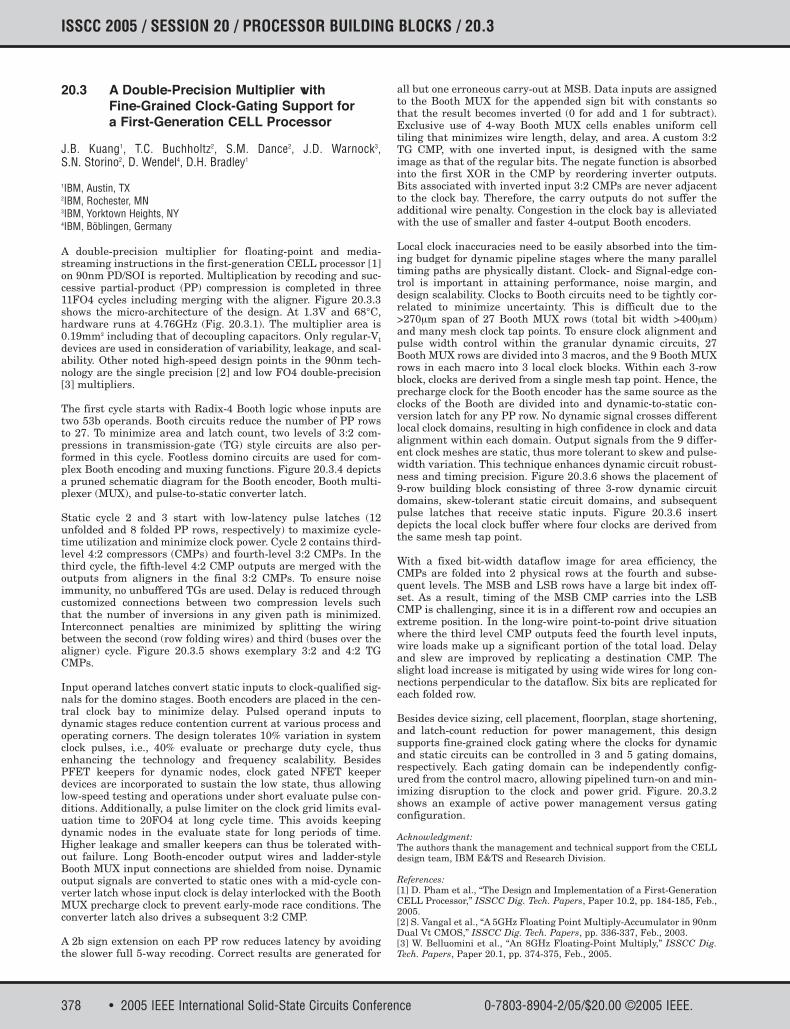
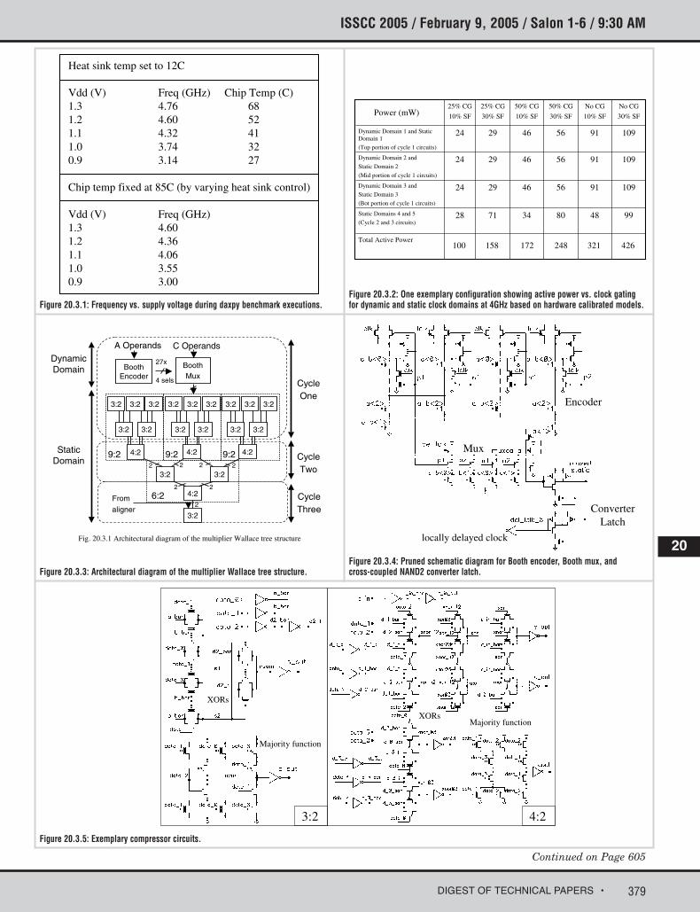
A double-precision multiplier for floating-point and media-streaming instructions in the first-generation CELL processor [1]on 90nm PD/SOI is reported. Multiplication by recoding and suc-cessive partial-product (PP) compression is completed in three11FO4 cycles including merging with the aligner. Figure 20.3.3shows the micro-architecture of the design. At 1.3V and 68°C,hardware runs at 4.76GHz (Fig. 20.3.1). The multiplier area is0.19mm2 including that of decoupling capacitors. Only regular-Vtdevices are used in consideration of variability, leakage, and scal-ability. Other noted high-speed design points in the 90nm tech-nology are the single precision [2] and low FO4 double-precision[3] multipliers.
The first cycle starts with Radix-4 Booth logic whose inputs aretwo 53b operands. Booth circuits reduce the number of PP rowsto 27. To minimize area and latch count, two levels of 3:2 com-pressions in transmission-gate (TG) style circuits are also per-formed in this cycle. Footless domino circuits are used for com-plex Booth encoding and muxing functions. Figure 20.3.4 depictsa pruned schematic diagram for the Booth encoder, Booth multi-plexer (MUX), and pulse-to-static converter latch.
Static cycle 2 and 3 start with low-latency pulse latches (12unfolded and 8 folded PP rows, respectively) to maximize cycle-time utilization and minimize clock power. Cycle 2 contains third-level 4:2 compressors (CMPs) and fourth-level 3:2 CMPs. In thethird cycle, the fifth-level 4:2 CMP outputs are merged with theoutputs from aligners in the final 3:2 CMPs. To ensure noiseimmunity, no unbuffered TGs are used. Delay is reduced throughcustomized connections between two compression levels suchthat the number of inversions in any given path is minimized.Interconnect penalties are minimized by splitting the wiringbetween the second (row folding wires) and third (buses over thealigner) cycle. Figure 20.3.5 shows exemplary 3:2 and 4:2 TGCMPs.
Input operand latches convert static inputs to clock-qualified sig-nals for the domino stages. Booth encoders are placed in the cen-tral clock bay to minimize delay. Pulsed operand inputs todynamic stages reduce contention current at various process andoperating corners. The design tolerates 10% variation in systemclock pulses, i.e., 40% evaluate or precharge duty cycle, thusenhancing the technology and frequency scalability. BesidesPFET keepers for dynamic nodes, clock gated NFET keeperdevices are incorporated to sustain the low state, thus allowinglow-speed testing and operations under short evaluate pulse con-ditions. Additionally, a pulse limiter on the clock grid limits eval-uation time to 20FO4 at long cycle time. This avoids keepingdynamic nodes in the evaluate state for long periods of time.Higher leakage and smaller keepers can thus be tolerated with-out failure. Long Booth-encoder output wires and ladder-styleBooth MUX input connections are shielded from noise. Dynamicoutput signals are converted to static ones with a mid-cycle con-verter latch whose input clock is delay interlocked with the BoothMUX precharge clock to prevent early-mode race conditions. Theconverter latch also drives a subsequent 3:2 CMP.
A 2b sign extension on each PP row reduces latency by avoidingthe slower full 5-way recoding. Correct results are generated for
all but one erroneous carry-out at MSB. Data inputs are assignedto the Booth MUX for the appended sign bit with constants sothat the result becomes inverted (0 for add and 1 for subtract).Exclusive use of 4-way Booth MUX cells enables uniform celltiling that minimizes wire length, delay, and area. A custom 3:2TG CMP, with one inverted input, is designed with the sameimage as that of the regular bits. The negate function is absorbedinto the first XOR in the CMP by reordering inverter outputs.Bits associated with inverted input 3:2 CMPs are never adjacentto the clock bay. Therefore, the carry outputs do not suffer theadditional wire penalty. Congestion in the clock bay is alleviatedwith the use of smaller and faster 4-output Booth encoders.
Local clock inaccuracies need to be easily absorbed into the tim-ing budget for dynamic pipeline stages where the many paralleltiming paths are physically distant. Clock- and Signal-edge con-trol is important in attaining performance, noise margin, anddesign scalability. Clocks to Booth circuits need to be tightly cor-related to minimize uncertainty. This is difficult due to the>270µm span of 27 Booth MUX rows (total bit width >400µm)and many mesh clock tap points. To ensure clock alignment andpulse width control within the granular dynamic circuits, 27Booth MUX rows are divided into 3 macros, and the 9 Booth MUXrows in each macro into 3 local clock blocks. Within each 3-rowblock, clocks are derived from a single mesh tap point. Hence, theprecharge clock for the Booth encoder has the same source as theclocks of the Booth are divided into and dynamic-to-static con-version latch for any PP row. No dynamic signal crosses differentlocal clock domains, resulting in high confidence in clock and dataalignment within each domain. Output signals from the 9 differ-ent clock meshes are static, thus more tolerant to skew and pulse-width variation. This technique enhances dynamic circuit robust-ness and timing precision. Figure 20.3.6 shows the placement of9-row building block consisting of three 3-row dynamic circuitdomains, skew-tolerant static circuit domains, and subsequentpulse latches that receive static inputs. Figure 20.3.6 insertdepicts the local clock buffer where four clocks are derived fromthe same mesh tap point.
With a fixed bit-width dataflow image for area efficiency, theCMPs are folded into 2 physical rows at the fourth and subse-quent levels. The MSB and LSB rows have a large bit index off-set. As a result, timing of the MSB CMP carries into the LSBCMP is challenging, since it is in a different row and occupies anextreme position. In the long-wire point-to-point drive situationwhere the third level CMP outputs feed the fourth level inputs,wire loads make up a significant portion of the total load. Delayand slew are improved by replicating a destination CMP. Theslight load increase is mitigated by using wide wires for long con-nections perpendicular to the dataflow. Six bits are replicated foreach folded row.
Besides device sizing, cell placement, floorplan, stage shortening,and latch-count reduction for power management, this designsupports fine-grained clock gating where the clocks for dynamicand static circuits can be controlled in 3 and 5 gating domains,respectively. Each gating domain can be independently config-ured from the control macro, allowing pipelined turn-on and min-imizing disruption to the clock and power grid. Figure. 20.3.2shows an example of active power management versus gatingconfiguration.
Acknowledgment:The authors thank the management and technical support from the CELLdesign team, IBM E&TS and Research Division.
References:[1] D. Pham et al., “The Design and Implementation of a First-GenerationCELL Processor,” ISSCC Dig. Tech. Papers, Paper 10.2, pp. 184-185, Feb.,2005.[2] S. Vangal et al., “A 5GHz Floating Point Multiply-Accumulator in 90nmDual Vt CMOS,” ISSCC Dig. Tech. Papers, pp. 336-337, Feb., 2003.[3] W. Belluomini et al., “An 8GHz Floating-Point Multiply,” ISSCC Dig.Tech. Papers, Paper 20.1, pp. 374-375, Feb., 2005.
379DIGEST OF TECHNICAL PAPERS •
Continued on Page 605
ISSCC 2005 / February 9, 2005 / Salon 1-6 / 9:30 AM
Figure 20.3.1: Frequency vs. supply voltage during daxpy benchmark executions.Figure 20.3.2: One exemplary configuration showing active power vs. clock gatingfor dynamic and static clock domains at 4GHz based on hardware calibrated models.
Figure 20.3.3: Architectural diagram of the multiplier Wallace tree structure.
Figure 20.3.5: Exemplary compressor circuits.
Figure 20.3.4: Pruned schematic diagram for Booth encoder, Booth mux, andcross-coupled NAND2 converter latch.
Heat sink temp set to 12C
Vdd (V) Freq (GHz) Chip Temp (C)1.3 4.76 681.2 4.60 521.1 4.32 411.0 3.74 320.9 3.14 27
Chip temp fixed at 85C (by varying heat sink control)
Vdd (V) Freq (GHz)1.3 4.601.2 4.361.1 4.061.0 3.550.9 3.00
Total Active Power
Static Domains 4 and 5
(Cycle 2 and 3 circuits)
Dynamic Domain 3 and
Static Domain 3
(Bot portion of cycle 1 circuits)
Dynamic Domain 2 and
Static Domain 2
(Mid portion of cycle 1 circuits)
Dynamic Domain 1 and Static Domain 1
(Top portion of cycle 1 circuits)
994880347128
1099156462924
1099156462924
1099156462924
No CG
30% SF
No CG
10% SF
50% CG
30% SF
50% CG
10% SF
25% CG
30% SF
25% CG
10% SF
100 158 172 248 321 426
Power (mW)
Fig. 20.3.1 Architectural diagram of the multiplier Wallace tree structure
CycleOne
CycleTwo
CycleThree
3:2 3:2
4:2
3:2
BoothEncoder
BoothMux
27x
4 sels
A Operands C Operands
2 2
From
aligner
2 2
2
4:2 4:2 4:2
3:2 3:2
3:2 3:2 3:2
3:2 3:2
3:2 3:2 3:2
3:2 3:2
3:2 3:2 3:2
2 2
9:2 9:2 9:2
6:2
DynamicDomain
StaticDomain
Encoder
Mux
ConverterLatch
locally delayed clock
3:2
Majority function
XORs
4:2
Majority functionXORs
20

605 • 2005 IEEE International Solid-State Circuits Conference 0-7803-8904-2/05/$20.00 ©2005 IEEE.
ISSCC 2005 PAPER CONTINUATIONS
Figure 20.3.6: Local clock arrangement.
Figure 20.3.7: Physical view of the multiplier. Decoupling capacitors arepopulated outside trapezoidal areas and inserted at the vicinity ofdynamic stages and input latches for power grid robustness.
: mesh clock drop point
lclkTo Booth encoder
To 3 Booth mux rows del_clk_b (top)
del_clk_b (mid)
del_clk_b (bot)
Dynamic Domain Clock Buffer in each shaded box
3 Booth Rows
First-level 3to2 compression
3 Booth Rows
First-level 3to2 compression
3 Booth Rows
First-level 3to2 compression
Second-level 3to2 compression
Cycle-boundary pulse latch rows
(Dynamic Domain)
(Dynamic Domain)
(Dynamic Domain)
9 ladder-styleBooth rows
9 ladder-styleBooth rows
9 ladder-styleBooth rows
Clock bay
dataflow