issn 1755-4535 minimum inverter capacity design for lc … · 2015-03-24 · minimum inverter...
TRANSCRIPT

www.ietdl.org
Published in IET Power ElectronicsReceived on 22nd November 2011Revised on 2nd May 2012doi: 10.1049/iet-pel.2011.0436
ISSN 1755-4535
Minimum inverter capacity design for LC-hybridactive power filters in three-phase four-wiredistribution systemsC.-S. Lam1 X.-X. Cui1 W.-H. Choi1 M.-C. Wong1 Y.-D. Han1,2
1Department of Electrical and Computer Engineering, University of Macau, Macao, People’s Republic of China2Department of Electrical Engineering, Tsinghua University, Beijing, People’s Republic of ChinaE-mail: [email protected]
Abstract: This study presents a minimum inverter capacity design for three-phase four-wire centre-split inductor-capacitor (LC)coupling hybrid active power filters (LC-HAPFs). Based on its equivalent circuit models in d–q–0 coordinate, the coupling partfiltering characteristics of the LC-HAPF without or with neutral inductor can be more clearly illustrated and easily understood,compared with the past analysis based on the generic filter structure. According to the current quality data, the minimum dc-linkvoltage expressions for the LC-HAPF without and with neutral inductor are deduced and compared. Conventionally, the couplingLC is usually tuned at a higher fifth- or seventh-order harmonic frequency to reduce its cost and size compared with third-ordercase. When triplen harmonic currents exist significantly, the LC-HAPF with a small tuned neutral inductor can further reduce itsminimum dc-link voltage requirement. Thus, the initial cost, switching loss and switching noise of the LC-HAPF can be lowered.Representative simulation and experimental results of the three-phase four-wire LC-HAPF with neutral inductor are presented toverify the filtering characteristics analysis and minimum dc-link voltage expressions, to show the effectiveness of reducing itsinverter capacity, switching loss and switching noise in current quality compensation compared with the conventional LC-HAPF.
1 Introduction
Nowadays, because of the rapid growth of advanced powerconversion devices and power electronic equipments, theirfull wave rectifier front-ends make the power quality issuesbecome more serious, especially in harmonic current (3rd,5th, 7th, 9th etc.) and reactive power problems. Highcurrent harmonic distortion causes various problems in bothdistribution systems and consumer products, such asequipment overheating, blown capacitor fuses, mal-operation of the protection devices, transformer overheatingand so on [1, 2]. The triplen harmonic currents (especiallythird order) drawn by these rectifier front ends willaccumulate in the neutral conductor, which results inincreasing the risk for stray voltage complaints especiallynear substations and the electromagnetic field (EMF) levelsnear three-phase distribution feeders [3]. Excess neutralcurrent will also overheat and even burn the neutralconductor. In addition, the rectifier front-ends usuallyaccompany with low-power factor problem as well. Thelarger the reactive current/power, the larger the systemlosses and the lower the network stability. Owing to thesereasons, electrical utilities usually charge the industrial andcommercial customers a higher electricity cost with low-power factor situation.
To eliminate those harmonic current and reactive powerproblems, power filters can be implemented. Since the firstinstallation of passive power filters (PPFs) in the mid-1940s,
956
& The Institution of Engineering and Technology 2012
PPFs have been widely used to suppress harmonic currentand compensate reactive power in distribution powersystems [4–7] because of their low cost, simplicity andhigh efficiency characteristics. Unfortunately, they havemany disadvantages such as low dynamic performance,filtering characteristics easily be affected by small variationsof the system parameter values and resonance problems [4–6, 8–10]. Since the concept ‘Active ac Power Filter’(APFs) was first developed by L. Gyugyi in 1976 [7, 11],the research studies of the APFs for current qualitycompensation are prospering since then. APFs canovercome the disadvantages inherent in PPFs, but the initialand operational costs are relatively high [4, 5, 8–16]because its dc-link operating voltage should be higher thanthe system voltage during inductive loading. This results inslowing down their large-scale application in distributionnetworks. Later on, different hybrid active power filter(HAPF) topologies composed of active and passive parts inseries and/or parallel have been proposed, aiming toimprove the compensation characteristics of PPFs andreduce the voltage and/or current ratings (costs) of theAPFs, thus providing a cost-effective solution forcompensating harmonic and reactive current problems [8–11, 14–24]. Among different HAPF topologies in [8–11,14–19], a transformerless LC coupling HAPF (LC-HAPF)has been recently proposed, applied for current qualitycompensation and damping of harmonic propagation indistribution power systems [18, 20–23], in which it has less
IET Power Electron., 2012, Vol. 5, Iss. 7, pp. 956–968doi: 10.1049/iet-pel.2011.0436

www.ietdl.org
passive components and lower dc-link operating voltagecomparing with an APF [20]. In addition, the coupling LCis designed based on the fundamental reactive powerconsumption of the loading and tuned harmonic frequency.To reduce the cost and size compared with that tuned at thethird-order case, they are conventionally tuned at the fifth-or seventh-order harmonic frequencies [17, 20–23]. Inaddition, the LC-HAPF should be switched off during noload or light load situations for preventing over-compensation.
To improve filtering performances for the coupling part ofthe three-phase four-wire LC-HAPF without adding any extraLC branches, the authors in [25] has presented an analysis forthe LC-HAPF with a neutral inductor. Through the genericfilter structure under positive, negative and zero-sequenceanalysis, instead of having only one filtering resonantfrequency from the coupling LC, the LC-HAPF with atuned neutral inductor can provide two different resonantfrequencies simultaneously in order to predominantly drainharmonic current away at these two frequencies [25].However, the coupling part filtering improvement analysisbased on the generic filter structure is not as obvious andcomprehensible as the deduced equivalent circuit models ind–q–0 coordinate in this paper. Moreover, because of thelimitations among the existing literatures [21–25], there isstill no mathematical deduction for the design of the LC-HAPF minimum dc-link voltage in current harmonics andreactive power compensation. Therefore the keycontribution of this paper is to investigate and discuss theminimum dc-link voltage design for a three-phase four-wireLC-HAPF with and without neutral inductor. So that theinverter capacity reduction analysis by adding a neutralinductor can be mathematically found.
In the following, a transformerless two-level three-phasefour-wire centre-split LC-HAPF and its correspondingequivalent circuit models in d–q–0 coordinate are initiallyintroduced in Section 2. Based on these circuit models, itscoupling part filtering characteristics without and withneutral inductor are analysed and discussed. According tothe current quality of the loading and the LC-HAPF single-phase equivalent circuit models in a–b–c coordinate, theminimum dc-link voltage expressions for the LC-HAPFwithout and with neutral inductor are proposed in Section3. Finally, representative simulation and experimentalresults of the three-phase four-wire centre-split LC-HAPFwith neutral inductor are given to verify its filteringcharacteristics and the minimum dc-link voltage designexpressions, to show the effectiveness of reducing its dc-link voltage requirement, switching loss and switchingnoise in current quality compensation compared with theconventional LC-HAPF without neutral inductor. Given thatmost of the loadings in the distribution power systems areinductive, the following analysis and discussion only focuson inductive non-linear loads [26].
2 Mathematical modelling of atransformerless two-level three-phase four-wire centre-split LC-HAPF in d–q–0 coordinate
2.1 Equivalent circuit models of a three-phasefour-wire LC-HAPF in d–q–0 coordinate
A transformerless two-level three-phase four-wire centre-splitLC-HAPF with neutral inductor is shown in Fig. 1a, in whichthe non-linear loads can be modelled as three single-phase fullbridge diode rectifiers. The corresponding equivalent circuit
IET Power Electron., 2012, Vol. 5, Iss. 7, pp. 956–968doi: 10.1049/iet-pel.2011.0436
model of LC-HAPF in a–b–c coordinate is shown inFig. 1b, where the subscript ‘x ’ denotes phase a, b, c, n. vx
is the load voltage, isx, iLx and icx are the system, load andinverter current for each phase. Cc and Lc are the couplingpart capacitor and inductor for each leg of the three-phasevoltage source inverter (VSI). vCcx and vLcx are the couplingcapacitor voltage and inductor voltage. Ln and vLn is theneutral inductor and neutral inductor voltage of the three-phase VSI. Cdc and Vdc are the dc capacitor, upper andlower dc capacitor voltages. The dc-link voltage is assumedas an ideal voltage source of 2Vdc, and vinvx is the inverteroutput voltage.
From Fig. 1b, the differential equations of the couplinginductor Lc and capacitor Cc can be expressed as
Lc
d
dt
ica
icb
icc
⎡⎢⎣
⎤⎥⎦=
vinva
vinvb
vinvc
⎡⎢⎣
⎤⎥⎦+Ln
d
dt
icn
icn
icn
⎡⎢⎣
⎤⎥⎦−
va
vb
vc
⎡⎢⎣
⎤⎥⎦−
vCca
vCcb
vCcc
⎡⎢⎣
⎤⎥⎦
⎛⎜⎝
⎞⎟⎠
(1)
Cc
d
dt
vCca
vCcb
vCcc
⎡⎣
⎤⎦=−
ica
icb
icc
⎡⎣
⎤⎦ (2)
With the help of [27, 28], after applying Park transformation,(1) and (2) in the d–q–0 rotating coordinate can be expressedas
vLc
−icq
icd
0
⎡⎢⎣
⎤⎥⎦+Lc
d
dt
icd
icq
ic0
⎡⎢⎣
⎤⎥⎦=
vinvd
vinvq
vinv0
⎡⎢⎣
⎤⎥⎦− 3Ln
d
dt
0
0
ic0
⎡⎢⎣
⎤⎥⎦
−vd
vq
v0
⎡⎢⎣
⎤⎥⎦−
vCcd
vCcq
vCc0
⎡⎢⎣
⎤⎥⎦
⎛⎜⎝
⎞⎟⎠ (3)
vCc
−vCcq
vCcd
0
⎡⎣
⎤⎦+Cc
d
dt
vCcd
vCcq
vCc0
⎡⎣
⎤⎦=−
icd
icq
ic0
⎡⎣
⎤⎦ (4)
where v is the angular frequency of the d–q–0 rotatingcoordinate frame, and is synchronised with the linefrequency. When LC-HAPF does not contain Ln (Ln ¼ 0),(4) remains the same and (3) becomes
vLc
−icq
icd
0
⎡⎢⎣
⎤⎥⎦+ Lc
d
dt
icd
icq
ic0
⎡⎢⎣
⎤⎥⎦=
vinvd
vinvq
vinv0
⎡⎢⎣
⎤⎥⎦−
vd
vq
v0
⎡⎢⎣
⎤⎥⎦−
vCcd
vCcq
vCc0
⎡⎢⎣
⎤⎥⎦
⎛⎜⎝
⎞⎟⎠
(5)
According to (3)–(5), the equivalent circuit models of thethree-phase four-wire centre-split LC-HAPF without andwith Ln in d–q–0 coordinate can be shown in Figs. 1c– f.
2.2 Coupling part filtering characteristics analysisof the LC-HAPF without or with neutral inductor
From Figs. 1c, d and f, Ln will not influence the d, q-coordinate circuit models of the LC-HAPF, but it willinfluence the 0-coordinate circuit model only. Comparedwith the 0-coordinate circuit model without Ln as in Fig. 1e,
957
& The Institution of Engineering and Technology 2012

www.ietdl.org
Fig. 1 Transformerless two-level three-phase four-wire centre-split LC-HAPF
a Circuit configuration with Ln
b Equivalent circuit model with Ln in a–b–c coordinatec d-coordinate equivalent circuit model without or with Ln in d–q–0 coordinated q-coordinate equivalent circuit model without or with Ln in d–q–0 coordinatee 0-coordinate equivalent circuit model without Ln in d–q–0 coordinatef 0-coordinate equivalent circuit model with Ln in d–q–0 coordinate
when Ln is added, there is actually an added inductor of 3Ln tothe 0-coordinate circuit model, as shown in Fig. 1f.
From Figs. 1c–e, without Ln, the resonant frequency of thecoupling part of the LC-HAPF in d, q and 0-coordinate circuitmodels are the same
fdq NL = f0 NL = 1
2p������LcCc
√ (6)
where fdq_NL and f0_NL are the coupling part resonantfrequencies for the LC-HAPF d, q-coordinate circuit modelsand 0-coordinate circuit model without Ln situation, thesubscript ‘_NL ’ denotes the system without Ln. This resultimplies that the coupling part can only possess one resonant
958
& The Institution of Engineering and Technology 2012
frequency for filtering current harmonics, which can beverified by Fig. 2a.
From Figs. 1c, d and f, with Ln, the resonant frequency ofthe coupling part of the LC-HAPF in d, q and 0-coordinatecircuit models can be expressed as
fdq L = 1
2p������LcCc
√ (7)
f0 L = 1
2p���������������(3Ln + Lc)Cc
√ (8)
where fdq_L and f0_L ( f0_L , fdq_L) are the coupling partresonant frequencies for the LC-HAPF d, q-coordinate
IET Power Electron., 2012, Vol. 5, Iss. 7, pp. 956–968doi: 10.1049/iet-pel.2011.0436

www.ietdl.org
Fig. 2 Coupling part impedance of the LC-HAPF in d–q–0 coordinate circuit models
a Without Ln
b With Ln
circuit models and 0-coordinate circuit model with Ln
situation, the subscript ‘_L ’ denotes the system with Ln.From (7) and (8), it is clearly illustrated that the LC-HAPFcan have two different resonant frequencies for filteringcurrent harmonics after the addition of Ln, which can beverified by Fig. 2b. Fig. 2 is plotted based on the LC-HAPFsystem parameters as in Table 2.
The above analysis clearly shows that the three-phase four-wire centre-split LC-HAPF without and with Ln will havethe same d, q-coordinate but different 0-coordinate circuitmodels. Moreover, the LC-HAPF with Ln can have twodifferent resonant frequencies for harmonic current filteringas indicated by (7) and (8), whereas the LC-HAPF withoutLn can only have one as indicated by (6), in which thededuced results based on the circuit models in d–q–0coordinate are equivalent as those deduced through thegeneric filter structure under positive, negative and zero-sequence analysis [25]. In the following, the resonantfrequency selection for the coupling LC without or with Ln
will be discussed.
Table 1 Characteristics of the LC-HAPF without and with Ln
LC-HAPF No. of resonant
frequency order
for filtering
harmonics
No. of LC
components
Capacity of
the inverter
L C
without Ln 1 3 3 Larger
with Ln 2 4 3 Smaller
Table 2 LC-HAPF system parameters for simulations and
experiments
System parameters Physical values
system source-side Vx 220 Vrms
F 50 Hz
LC-HAPF Lc 8 mH
Cc 50 uF
Cdc 3.3 mF
Vdc 22.5 V, 32.5 V, 45.0 V
Ln 5 mH
non-linear rectifier load RLx 43.2 V
LLx 34.5 mH
CLx 392.0 uF
IET Power Electron., 2012, Vol. 5, Iss. 7, pp. 956–968doi: 10.1049/iet-pel.2011.0436
2.3 Resonant frequency selection for coupling LCwithout or with neutral inductor
Under balanced non-linear loadings consideration, thefiltering characteristics and resonant frequency selection forthe coupling LC without or with Ln can be determined asfollows.
1. When the loading contains 3kth (k ¼ 1, 2, . . . , 1) orderharmonic current only: Since 3kth order harmonic currentpresents in the 0-coordinate circuit model only, the couplingLC without and with Ln can both be tuned at the dominant3kth order harmonic frequency ( f0_NL and f0_L). From (6)and (8), for f0_NL ¼ f0_L consideration, a small Ln canalready significantly reduce the size of the three couplingLc, which benefits for lowering the system initial cost. Thecoupling LC without and with Ln can only provide one 3kthorder resonant frequency for harmonic current filtering, asindicated by Figs. 1c– f.2. When the loading contains 3k + 1th order harmoniccurrent only: Since 3k + 1th order harmonic currentpresents in the d, q-coordinate circuit models only, fromFigs. 1c and d, Ln cannot help to improve the coupling partfiltering performances under this loading situation. Thecoupling LC can be tuned at the dominant 3k + 1th orderharmonic frequency ( fdq_NL and fdq_L). The coupling LCwithout and with Ln can only provide one 3k + 1th orderresonant frequency for harmonic current filtering, asindicated by Figs. 1c– f.3. When the loading contains any order harmonic current:Since 3kth and 3k + 1th order harmonic currents can onlypresent in the 0-coordinate and d, q-coordinate circuitmodels, respectively, the coupling LC with Ln can providetwo resonant frequencies for eliminating one 3kth and one3k + 1th order harmonic currents, as indicated byFigs. 1c– f. Therefore the coupling LC with Ln can be tunedat one dominant 3kth and one dominant 3k + 1th orderharmonic frequency ( fdq_L and f0_L), where the 3kth ordermust be smaller than 3k + 1th order.
Owing to wide usage of personal computers,uninterruptible power supplies, high-frequency fluorescentlights, air-conditioning system, various office and consumerelectronics equipments in residential, commercial and officebuildings, both 3kth and 3k + 1th order harmonic currentsare usually present in those three-phase four-wiredistribution power systems [4], thus it is recommended toadd a Ln to the LC-HAPF.
959
& The Institution of Engineering and Technology 2012

www.ietdl.org
Fig. 3 LC-HAPF single-phase equivalent circuit model in a–b–c coordinate
a At fundamental frequency without or with Ln
b At nth ¼ 3k + 1th harmonic order frequency without or with Ln
c At nth ¼ 3kth harmonic order frequency without Ln
d At nth ¼ 3kth harmonic order frequency with Ln
Under unbalanced non-linear loadings consideration, both3kth and 3k + 1th order harmonic currents can present inthe d, q, 0-coordinate circuit models, the coupling LC withLn can be tuned at two dominant harmonic frequencies( fdq_L, f0_L) and ( f0_L , fdq_L). In the following, theminimum dc-link voltage expressions for the LC-HAPFwithout and with Ln will be proposed and presented.
3 Minimum inverter capacity analysis of athree-phase four-wire centre-split LC-HAPF
From the previous analysis results, Fig. 3 shows the LC-HAPF single-phase equivalent circuit model in a–b–ccoordinate without and with Ln. In the following analysis,all parameters are in root mean square (rms) value. InFig. 3, the required inverter fundamental output voltages(Vinvxf_NL, Vinvxf_L) and inverter harmonic output voltages(Vinvxn_NL, Vinvxn_L) at each harmonic order can be found,where the subscripts ‘f ’ and ‘n ’ denote the fundamental andharmonic frequency components. As Vinvxf_NL, Vinvxn_NL,Vinvxf_L and Vinvxn_L are in rms values, the minimum dc-linkvoltage values (Vdcxf_NL, Vdcxn_NL, Vdcxf_L, Vdcxn_L) forcompensating the phase fundamental reactive currentcomponent and each harmonic current component arecalculated as the peak values of the required inverterfundamental and harmonic output voltages, in whichVdcxf_NL ¼
��2
√Vinvxf_NL, Vdcxn_NL ¼
��2
√Vinvxn_NL, Vdcxf_L ¼��
2√
Vinvxf_L and Vdcxn_L ¼��2
√Vinvxn_L, respectively.
In order to provide sufficient dc-link voltage forcompensating load reactive and harmonic currents, theminimum dc-link voltage requirement (Vdcx_NL, Vdcx_L) ofthe LC-HAPF single-phase circuit model without and withLn as shown in (9) and (10) are deduced by considering theworst phase relation between each harmonic component, in
960
& The Institution of Engineering and Technology 2012
which their corresponding peak voltages of the VSI at ACside are assumed to be superimposed.
Vdcx NL =������������������������������|Vdcxf NL|2 +
∑1
n=2
|Vdcxn NL|2√
(9)
Vdcx L =����������������������������|Vdcxf L|2 +
∑1
n=2
|Vdcxn L|2√
(10)
From Fig. 3, as the Ln affects only the 3kth order harmonicimpedance of the coupling part, the LC-HAPF without andwith Ln obtain the same fundamental impedance of thecoupling part as shown in Fig. 3a. From Fig. 3a, when theload voltage Vx is pure sinusoidal without harmoniccomponents, Vx ¼ Vxf, the inverter fundamental outputvoltage of the LC-HAPF single-phase equivalent circuitmodel without and with Ln can be expressed as
Vinvxf NL = Vinvxf L = Vx + ZPFf × Icxf (11)
As most of the loadings in the distribution power systems areinductive, the fundamental impedance of the couplingcapacitor Cc should be larger than that of the couplinginductor Lc, that yields ZPFf ¼ |ZPFf|ejff, (ff ¼ 2908).When the LC-HAPF operates at ideal case, the fundamentalcompensating current Icxf contains the pure reactivecomponent Icxfq only without the active current componentIcxfp, therefore (11) can be rewritten as
Vinvxf NL = Vinvxf L = Vx − vLc −1
vCc
∣∣∣∣∣∣∣∣|Icxfq|, v = 2pf
(12)
IET Power Electron., 2012, Vol. 5, Iss. 7, pp. 956–968doi: 10.1049/iet-pel.2011.0436

www.ietdl.org
Table 3 Simulated and experimental fundamental reactive current, third, fifth, seventh and ninth orders load harmonic current values
Fundamental
reactive
current, A
Third-order harmonic
current, A
Fifth-order harmonic
current, A
Seventh-order harmonic
current, A
Ninth-order harmonic
current, A
simulation results 3.72 1.96 0.53 0.23 0.16
experimental results 3.41 1.92 0.45 0.20 0.12
When the LC-HAPF does not contain Ln, from Figs. 3b and c,the inverter harmonic output voltage Vinvxn_NL atnth ¼ 3k + 1th or 3kth (k ¼ 1, 2, . . . , 1) harmonic ordercan be expressed as
Vinvxn NL = nvLc −1
nvCc
∣∣∣∣∣∣∣∣|Icxn|, n = 2, 3 . . .1 (13)
where Icxn is the nth order harmonic compensating current.When the LC-HAPF contains Ln, from Figs. 3b and d, the
inverter harmonic output voltage Vinvxn_L at nth ¼ 3k + 1thor 3kth harmonic order can be expressed as (see (14))
When the LC-HAPF is performing compensation, theabsolute reactive and nth order harmonic compensatingcurrent should be equal to those of the loading, this yields
|Icxfq| = |ILxfq|, |Icxn| = |ILxn| (15)
where ILxfq and ILxn are the reactive and nth order harmoniccurrent of the loading.
From (11)–(15), the inverter fundamental and each nthharmonic order output voltages of the LC-HAPF single-phase circuit model without and with Ln (Vinvxf_NL,Vinvxn_NL, Vinvxf_L, Vinvxn_L) can be calculated. Then theminimum dc-link voltage requirement (Vdcx_NL, Vdcx_L) for
Fig. 4 Inverter capacity ratio SR between the LC-HAPF without orwith different Ln values
IET Power Electron., 2012, Vol. 5, Iss. 7, pp. 956–968doi: 10.1049/iet-pel.2011.0436
the LC-HAPF single-phase circuit model can be found by(9) and (10).
As the LC-HAPF aims to compensate reactive power andcurrent harmonics only but not to provide active power tobalance the system current during unbalanced loading case,the generalised single-phase p–q theory is chosen [29] inthis paper. By using the single-phase p–q theory, thereactive power and current harmonics in each phase can becompensated independently, thus the final requiredminimum dc-link voltage for the three-phase four-wirecentre-split LC-HAPF without and with Ln (Vdc_NL, Vdc_L)will be the maximum one among the calculated minimumvalue of each phase (Vdcx_NL, Vdcx_L), which are expressedin (16) and (17). Thus, the deduced minimum dc-linkvoltage expressions can work for both balanced andunbalanced loadings.
Vdc NL = Vdc = max (Vdca NL, Vdcb NL, Vdcc NL) (16)
Vdc L = Vdc = max (Vdca L, Vdcb L, Vdcc L) (17)
From (16) and (17), the inverter capacity of the LC-HAPFwithout and with Ln (Sinv_NL, Sinv_L) can be expressed as
Sinv NL = 3Vdc NL��
2√ Ic (18)
Sinv L = 3Vdc L��
2√ Ic (19)
where Ic ¼ max(Ica ¼ Icb ¼ Icc). From (18) and (19), theinverter capacity of the LC-HAPF without and with Ln isproportional to their corresponding dc-link voltage. Thus,the dc-link voltage level can reflect the inverter capacity ofthe LC-HAPF.
Table 6 summarises the minimum dc-link voltagededuction steps of the LC-HAPF without and with Ln.From Table 6, the minimum dc-link voltage value of theLC-HAPF can be calculated only when the spectra of theload currents are known. If the load current spectra cannotbe measured (unknown loads) before the installation of theLC-HAPF system, via fast Fourier transform (FFT), theload current spectra can also be figured out by the digitalsignal processor (DSP) of the LC-HAPF system afterinstallation. Then the minimum dc-link voltage value canbe calculated by the DSP through the deduction steps inTable 6. Once the minimum dc-link voltage value isknown, the LC-HAPF system can start operation. Throughthe dc-link voltage control method, the dc-link voltage of
Vinvxn L =Vinvx3k+1 L = (3k + 1)vLc −
1
(3k + 1)vCc
∣∣∣∣∣∣∣∣|Icx3k+1|
Vinvx3k L = 3kv(Lc + 3Ln) − 1
3kvCc
∣∣∣∣∣∣∣∣|Icx3k |
,
⎧⎪⎪⎨⎪⎪⎩
k = 1, 2 . . .1n = 2, 3 . . .1
(14)
961
& The Institution of Engineering and Technology 2012

www.ietdl.org
Fig. 5 Control block diagram for the three-phase four-wire centre-split LC-HAPF
the LC-HAPF can be controlled to reach this minimumreference value.
For the three single-phase full bridge rectifier loadings asshown in Fig. 1a are approximately balanced, from (18)and (19), the inverter capacity ratio SR between the LC-HAPF with and without Ln can be expressed as
SR = Sinv L
Sinv NL
= Vdc L
Vdc NL
= Vdcx L
Vdcx NL
(20)
As the load harmonic currents are mainly contributed by thethird-, fifth-, seventh- and ninth-harmonic orders, thecoupling part with Ln are tuned at the fifth- and third-harmonic orders, respectively. For the simulated LC-HAPFsystem parameters and balanced loading situations as shownin Tables 2 and 3, Fig. 4 shows the SR between the LC-HAPF without and with different Ln values. From Fig. 4,when Ln is chosen at around 4.5 mH, the minimum invertercapacity of the LC-HAPF can be achieved. Moreover, theinverter capacity of the LC-HAPF with Ln (Ln ¼ 4 to5 mH) can be reduced by more than 50% of that without Ln
(Ln ¼ 0 mH).From the above analysis, when the 3kth and 3k + 1th order
harmonic contents dominate the load harmonic current in athree-phase four-wire system, through appropriate design ofthe coupling part (Lc, Cc) and Ln, the LC-HAPF with Ln
can reduce its inverter capacity compared with the LC-HAPF without Ln. The coupling part is required to be tunedat 3k + 1th order harmonic frequency because the couplingpart with Ln can only eliminate the 3kth order harmoniccurrent. Moreover, the 3kth harmonic order should besmaller than the 3k + 1th harmonic order.
Although the use of the Ln will increase one passivecomponent of the LC-HAPF, it may effectively reduce the
962
& The Institution of Engineering and Technology 2012
minimum dc-link voltage requirement, so as to lower theLC-HAPF system initial cost. Moreover, since the switchingloss is directly proportional to the dc-link voltage [30], theLC-HAPF with Ln will obtain less switching loss if a lowerdc-link voltage is used, and vice versa. Besides, the systemcan also obtain less switching noise, so as to improve itscompensation performances. Table 1 summarises thecharacteristics of the LC-HAPF without and with Ln.
4 Simulation and experimental verifications
In order to verify the filtering characteristics and minimum dc-link voltage analysis in Sections 2 and 3, representativesimulation and experimental results of the three-phase four-wire centre-split LC-HAPF system without and with Ln asshown in Fig. 1a will be given. The non-linear loads arecomposed of three single-phase full bridge rectifiers, whichact as harmonic producing loads. In order to simplify theverification in this paper, the dc-link is supported by externaldc voltage source and the simulated and experimental three-phase loadings are approximately balanced. Table 2 lists thesimulated and experimental system parameters for the LC-HAPF. From Table 2, the coupling Lc and Cc are designedbased on the load fundamental reactive power consumptionand tuned at the fifth-order harmonic frequency, and thecoupling part with Ln are tuned at the third-order harmonicfrequency. As the simulated and experimental loadings areapproximately balanced, only phase a compensationdiagrams will be illustrated. Simulation studies were carriedout by using Matlab.
In order to verify the simulation results, a transformerlesstwo-level three-phase four-wire centre-split LC-HAPFprototype is also implemented in the laboratory. insulatedgate bipolar transistors (IGBTs) are employed as the
IET Power Electron., 2012, Vol. 5, Iss. 7, pp. 956–968doi: 10.1049/iet-pel.2011.0436

www.ietdl.org
Fig. 6 Simulated and experimental system current isx and compensating current icx waveforms and their spectra of phase a before and afterLC-HAPF compensation
Simulated results:a isa before compensationb isa after compensation with Vdc ¼ 22.5 V (Ln ¼ 0)c isa after compensation with Vdc ¼ 32.5 V (Ln ¼ 0)d isa after compensation with Vdc ¼ 45.0 V (Ln ¼ 0)
switching devices for the active inverter part. And the controlsystem of the prototype is a DSP TMS320F2812 and theanalog-to-digital (A/D) sampling frequency of the LC-HAPFsystem is set at 25 kHz. The three-phase load voltages vx,load currents iLx and compensating currents icx are measuredby Hall effect transducers with signal conditioning boards.Then the signal conditioning boards will transfer the largeelectrical signals (vx, iLx, icx) into small analog signals inorder to be adopted as the A/D converter inputs of the DSP.Those signals are necessary to determine the referencecompensating currents i∗cx and generate the corresponding icx.Fig. 5 shows the reactive and harmonic referencecompensating current deduction and pulse width modulation(PWM) control block diagram for the three-phase four-wirecentre-split LC-HAPF. The instantaneous reference
IET Power Electron., 2012, Vol. 5, Iss. 7, pp. 956–968doi: 10.1049/iet-pel.2011.0436
compensating current i∗cx can be determined by the single-phase p–q theory [29]. Initially, the phase instantaneousactive power pLx and reactive power qLx are calculated bypLx ¼ vxaiLxa+ vxbiLxb and qLx ¼ vxaiLxb–vxbiLxa. Tocompensate the reactive power and current harmonicsgenerated by the load, i∗cx for each phase can be calculatedby i∗cx = (1/Ax)[−vxa · pLx + vxb · qLx], whereAx = v2
xa + v2xb. The term pLx can easily be extracted from
pLx by using a low-pass filter (LPF) or high-pass filter(HPF). After the process of the instantaneous i∗cxdetermination, the compensating current error Dicx togetherwith hysteresis band H will be sent to the current PWMcontrol part and the PWM trigger signals for the switchingdevices of the VSI can then be generated. And this controlblock diagram will be applied for the LC-HAPF system in
963
& The Institution of Engineering and Technology 2012

www.ietdl.org
Fig. 6 Continued
e isa after compensation with Vdc ¼ 22.5 V (Ln ¼ 5 mH)f ica with Vdc ¼ 45.0 V (Ln ¼ 0)g ica with Vdc ¼ 22.5 V (Ln ¼ 5 mH)Experimental results:h isa before compensation
order to generate the required compensating current icx. In thefollowing, since the load harmonic current contents beyond theninth order are small, for simplicity, the required minimum dc-link voltage calculation will be taken into account up to ninthharmonic order only.
4.1 Simulation results
Fig. 6a illustrates the simulated load current iLx waveform andits spectrum of phase a, in which its correspondingfundamental reactive current, third-, fifth-, seventh- andninth-order harmonic current in rms values are shown inTable 3. From Fig. 6a and Table 5, the total harmonicdistortion (THD) of the load current (THDiLx
) is 32.1% andthe load neutral current (iLn) is 5.35 Arms, in which the third
964
& The Institution of Engineering and Technology 2012
(3kth) and fifth (3k+ 1th) order harmonic contents dominatethe load harmonic current. With the help of Table 6, Table 4shows the required minimum dc-link voltage values(Vdcxf_NL, Vdcxn_NL, Vdcxf_L, Vdcxn_L) for compensating thefundamental reactive current, third, fifth, seventh and ninthharmonic current components and the minimum dc-linkvoltages (Vdc_NL, Vdc_L) of the LC-HAPF without and withLn, in which Vdc_NL ¼ 39.62 and Vdc_L ¼ 17.11 V,respectively. The dc-link voltage for the LC-HAPF is chosenas Vdc ¼ 22.5, 32.5, 45.0 V three levels for performingcompensation, respectively. After compensation by the LC-HAPF without and with Ln, Figs. 6b–e show the simulatedsystem current isx waveforms and their spectra of phase a atdifferent dc-link voltage levels. Moreover, theircorresponding simulation results are summarised in Table 5.
IET Power Electron., 2012, Vol. 5, Iss. 7, pp. 956–968doi: 10.1049/iet-pel.2011.0436
www.ietdl.org
Fig. 6 Continued
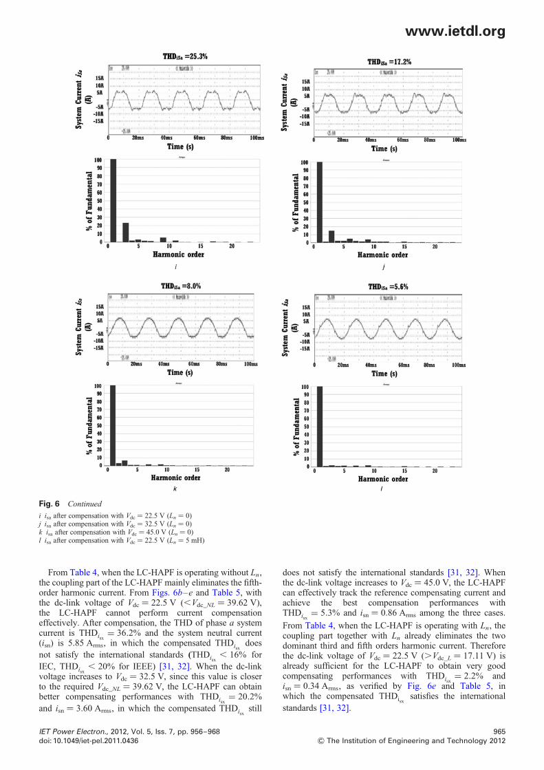
i isa after compensation with Vdc ¼ 22.5 V (Ln ¼ 0)j isa after compensation with Vdc ¼ 32.5 V (Ln ¼ 0)k isa after compensation with Vdc ¼ 45.0 V (Ln ¼ 0)l isa after compensation with Vdc ¼ 22.5 V (Ln ¼ 5 mH)
From Table 4, when the LC-HAPF is operating without Ln,the coupling part of the LC-HAPF mainly eliminates the fifth-order harmonic current. From Figs. 6b–e and Table 5, withthe dc-link voltage of Vdc ¼ 22.5 V (,Vdc_NL ¼ 39.62 V),the LC-HAPF cannot perform current compensationeffectively. After compensation, the THD of phase a systemcurrent is THDisx
= 36.2% and the system neutral current(isn) is 5.85 Arms, in which the compensated THDisx
doesnot satisfy the international standards (THDisx
, 16% forIEC, THDisx
, 20% for IEEE) [31, 32]. When the dc-linkvoltage increases to Vdc ¼ 32.5 V, since this value is closerto the required Vdc_NL ¼ 39.62 V, the LC-HAPF can obtainbetter compensating performances with THDisx
= 20.2%and isn ¼ 3.60 Arms, in which the compensated THDisx
still
IET Power Electron., 2012, Vol. 5, Iss. 7, pp. 956–968doi: 10.1049/iet-pel.2011.0436
does not satisfy the international standards [31, 32]. Whenthe dc-link voltage increases to Vdc ¼ 45.0 V, the LC-HAPFcan effectively track the reference compensating current andachieve the best compensation performances withTHDisx
= 5.3% and isn ¼ 0.86 Arms among the three cases.
From Table 4, when the LC-HAPF is operating with Ln, thecoupling part together with Ln already eliminates the twodominant third and fifth orders harmonic current. Thereforethe dc-link voltage of Vdc ¼ 22.5 V (.Vdc_L ¼ 17.11 V) isalready sufficient for the LC-HAPF to obtain very goodcompensating performances with THDisx
= 2.2% andisn ¼ 0.34 Arms, as verified by Fig. 6e and Table 5, inwhich the compensated THDisx
satisfies the international
standards [31, 32].
965
& The Institution of Engineering and Technology 2012

www.ietdl.org
4.2 Experimental results
Fig. 6h illustrates the experimental iLx waveform and itsspectrum of phase a, in which its correspondingfundamental reactive current, third, fifth, seventh and ninthload order harmonic current in rms values are shown inTable 3. From Fig. 6h and Table 5, the THDiLx
is 32.7%and the iLn is 5.77 Arms, in which the third (3kth) and fifth(3k + 1th) orders harmonic content dominates the loadharmonic current. With the help of Table 6, Table 4 showsthe required minimum dc-link voltage values (Vdcxf_NL,Vdcxn_NL, Vdcxf_L, Vdcxn_L) for compensating the fundamental
reactive current, third, fifth, seventh and ninth harmoniccurrent components and the minimum dc-link voltages ofthe LC-HAPF without and with Ln, in whichVdc_NL ¼ 40.77 V and Vdc_L ¼ 19.33 V, respectively.Similar as simulation part, the dc-link voltage for the LC-HAPF is chosen as Vdc ¼ 22.5, 32.5, 45.0 V three levels forperforming compensation, respectively. After compensationby the LC-HAPF without and with Ln, Figs. 6i– l show theexperimental isx waveforms and their spectra of phase a atdifferent dc-link voltage levels. Moreover, theircorresponding experimental results are summarised inTable 5.
Table 4 Simulated and experimental required dc-link voltage of the LC-HAPF without and with Ln
LC-HAPF, mH Vdcxf_NL,
Vdcxf_L, V
Vdcx3_NL,
Vdcx3_L, V
Vdcx5_NL,
Vdcx5_L, V
Vdcx7_NL,
Vdcx7_L, V
Vdcx9_NL,
Vdcx9_L, V
Required Vdc, V
simulation results Ln ¼ 0 10.56 37.92 0.13 2.77 3.52 39.62
Ln ¼ 5 10.56 1.26 0.13 2.76 13.11 17.11
experimental results Ln ¼ 0 16.42 37.15 0.10 2.40 2.64 40.77
Ln ¼ 5 16.42 1.24 0.10 2.40 9.83 19.33
Table 5 Summary of simulated and experimental results
LC-HAPF Vdc, V Third harmonic, % Fifth harmonic, % DPF THDisx, % isn (Arms)
simulation results without comp. – 31.5 8.6 0.80 32.1 5.35
LC-HAPF (Ln ¼ 0 mH) 22.5 36.2 6.1 1.00 36.2 5.85
32.5 25.2 1.1 1.00 20.2 3.60
45.0 2.7 0.6 1.00 5.3 0.86
LC-HAPF (Ln ¼ 5 mH) 22.5 0.5 1.0 1.00 2.2 0.34
experimental esults without comp. – 31.4 7.3 0.83 32.7 5.77
LC-HAPF (Ln ¼ 0 mH) 22.5 23.8 3.2 1.00 25.3 3.51
32.5 14.8 2.4 1.00 17.2 2.45
45.0 6.3 1.1 1.00 8.0 1.30
LC-HAPF (Ln ¼ 5 mH) 22.5 2.4 1.5 1.00 5.6 0.74
Fig. 6 Continued
m ica with Vdc ¼ 45.0 V (Ln ¼ 0)n ica with Vdc ¼ 22.5 V (Ln ¼ 5 mH)
966 IET Power Electron., 2012, Vol. 5, Iss. 7, pp. 956–968
& The Institution of Engineering and Technology 2012 doi: 10.1049/iet-pel.2011.0436

www.ietdl.org
From Table 4, when the LC-HAPF is operating without Ln,the coupling part of the LC-HAPF mainly eliminates the fifthorder harmonic current. From Figs. 6i– l and Table 5, withVdc ¼ 22.5 V (,Vdc_NL ¼ 40.77 V), the LC-HAPF cannotperform current compensation effectively. Aftercompensation, the THDisx
of phase a is 25.3% and the isn is3.51 Arms, in which the compensated THDisx
does notsatisfy the international standards [31, 32]. When the dc-link voltage increases to Vdc ¼ 32.5 V, since this value iscloser to the required Vdc_NL ¼ 40.77 V, the LC-HAPF canobtain better compensating performances withTHDisx
= 17.2% and isn ¼ 2.45 Arms, in which thecompensated THDisx
still does not satisfy the IEC standard[32]. When the dc-link voltage increases to Vdc ¼ 45.0 V,the LC-HAPF can achieve the best compensationperformances with THDisx
= 8.0% and isn ¼ 1.30 Arms
among the three cases. From Table 4, when the LC-HAPFis operating with Ln, the coupling part together with Ln
already eliminates the two dominant third- and fifth-ordersharmonic current. Therefore the dc-link voltage ofVdc ¼ 22.5 V (.Vdc_L ¼ 19.33 V) is already sufficient toobtain very good compensating performances withTHDisx
= 5.6% and isn ¼ 0.74 Arms, as verified by Fig. 6l
and Table 5, in which the compensated THDisxsatisfies the
international standards [31, 32].The experimental results are similar to the simulated results,
which verified the previous analyses of the LC-HAPF filteringcharacteristics and minimum dc-link voltage requirement. Inorder to obtain good compensating performances for the LC-HAPF, the dc-link operating voltage can be chosen as thecalculated minimum dc-link voltage (Vdc_NL, Vdc_L). From thesimulation and experimental results, the required dc-linkvoltages for the LC-HAPF with Ln can have a greatreduction of more than 50% compared with those withoutLn. Since the dc-link operating voltage reflects the invertercapacity, the LC-HAPF with Ln can significantly reduce itsinverter capacity. Besides, it can also reduce the switchingloss as the switching loss is directly proportional to the dc-link voltage [30], in which the experimental inverter powerloss (W) of the LC-HAPF with Ln (Vdc ¼ 22.5 V) can bereduced by more than 5.0% than that of the LC-HAPFwithout Ln (Vdc ¼ 45.0 V).
Figs. 6f and g and Figs. 6m and n show the LC-HAPFsimulated and experimental compensating current icx
waveforms and their spectra of phase a with Vdc ¼ 45.0 V(without Ln) and Vdc ¼ 22.5 V (with Ln ¼ 5 mH). FromFigs. 6f and g and Figs. 6m and n, since the ica harmoniccontents above 15th harmonic order (switching noise)shows a significant reduction by adding a Ln, thus the LC-HAPF with Ln can effectively reduce the switching noiseand also improve the compensation performances asverified by Table 5, in comparison with the conventionalLC-HAPF without Ln, because it just requires a lower dc-link voltage requirement for performing compensation.
Without Ln case, if the coupling Lc and Cc are tuned atthird-order harmonic frequency instead of fifth order, thedc-link voltage reduction with Ln may not be so significant.Unfortunately, by tuning Lc and Cc at third order harmonicfrequency, it will significantly increase the initial cost andsize of the LC-HAPF, because the required three couplingLc will be increased from 8 to 22.5 mH, compared with thecoupling Lc and Cc tuned at fifth order with a Ln of 5 mH only.
If 3kth order load harmonic current exists, by concerningabout (i) initial costs of both the passive part (Lc and Cc)and inverter part (dc-link voltage) and (ii) switching loss
IET Power Electron., 2012, Vol. 5, Iss. 7, pp. 956–968doi: 10.1049/iet-pel.2011.0436
and switching noise, it is cost effective for the coupling partof the LC-HAPF with Ln to be tuned at one dominant 3kthand one dominant 3k + 1th order harmonic currents(3kth , 3k + 1th).
5 Conclusion
This paper aims to investigate the minimum inverter capacitydesign for three-phase four-wire centre-split LC LC-HAPF.Firstly, the equivalent circuit models of the three-phasefour-wire centre-split LC coupling hybrid active powerfilters (LC-HAPF) in d–q–0 coordinate are built andproposed. Based on the circuit models, the triplen harmonicfiltering performance of the LC-HAPF can be improved byadding a tuned neutral inductor. After that, the minimumdc-link voltage expressions for the LC-HAPF without andwith neutral inductor are also deduced, which can work forboth balanced and unbalanced loadings. According to thecurrent quality of the loading and the minimum dc-linkvoltage expressions, the dc-link voltage reduction analysisfor the LC-HAPF with neutral inductor can bemathematically obtained. Thus, the initial cost, switchingloss and switching noise of the LC-HAPF can be loweredby the additional neutral inductor. Finally, simulation andexperimental results of the three-phase four-wire centre-splitLC-HAPF with neutral inductor are presented to verify itsfiltering characteristics and the deduced minimum dc-linkvoltage expressions, and to show the effectiveness ofreducing its dc-link voltage requirement (inverter capacity),switching loss, switching noise and improving the systemperformances in current quality compensation comparedwith the conventional LC-HAPF without neutral inductor.
6 Acknowledgment
The authors thank the Science and Technology DevelopmentFund, Macao SAR Government and Research Committee ofUniversity of Macau for their financial supports.
7 References
1 Subjek, J.S., Mcquilkin, J.S.: ‘Harmonics-causes, effects, measurementsand analysis’, IEEE Trans. Ind. Electron., 1990, 26, (6), pp. 1034–1042
2 Duarte, L.H.S., Alves, M.F.: ‘The degradation of power capacitors underthe influence of harmonics’. Proc. IEEE 10th Int. Conf. on Harmonicsand Quality of Power, 2002, vol. 1, pp. 334–339
3 Tran, T.Q., Conrad, L.E., Stallman, B.K.: ‘Electric shock and elevatedEMF levels due to triplen harmonics’, IEEE Trans. Power Del., 1996,11, (2), pp. 1041–1049
4 Quinn, C.A., Mohan, N.: ‘Active filtering of harmonic currents in three-phase, four-wire systems with three-phase and single-phase nonlinearloads’. Proc. IEEE Seventh Annual Applied Power Electronics Conf.and Exposition, APEC. 92, 1992, pp. 829–836
5 Singh, B., Al-Haddad, K., Chandra, A.: ‘A review of active filters forpower quality improvement’, IEEE Trans. Ind. Electron., 1999, 46,(5), pp. 960–971
6 de Camargo, R.F., Picheiro, H.: ‘Three-phase four-wire shunt activefilter to reduce voltage and current distortions in distribution systems’.Proc. IEEE 32nd Annual Conf. on Industrial Electronics, IECON. 06,2006, pp. 1884–1889
7 Senini, S.T., Wolfs, P.J.: ‘Systematic identification and review of hybridactive filter topologies’. Proc. IEEE 33rd Annual Power ElectronicsSpecialists Conf., PESC. 02, 2002, vol. 1, pp. 394–399
8 Salmeron, P., Litran, S.P.: ‘A control strategy for hybrid power filter tocompensate four-wires three-phase systems’, IEEE Trans. PowerElectron., 2010, 25, (7), pp. 1923–1931
9 Luo, A., Zhao, W., Deng, X., Shen, Z.J., Peng, J.-C.: ‘Dividingfrequency control of hybrid active power filter with multi-injectionbranches using improved ip– iq algorithm’, IEEE Trans. PowerElectron., 2009, 24, (10), pp. 2396–2405
967
& The Institution of Engineering and Technology 2012

www.ietdl.org
10 Luo, A., Shuai, Z.K., Shen, Z.J., Zhu, W.J., Xu, X.Y.: ‘Designconsiderations for maintaining dc-side voltage of hybrid active powerfilter with injection circuit’, IEEE Trans. Power Electron., 2009, 24,(1), pp. 75–84
11 Peng, F.Z., Akagi, H., Nabae, A.: ‘A new approach to harmoniccompensation in power systems – a combined system of shuntpassive and series active filters’, IEEE Trans. Ind. Appl., 1990, 26,(6), pp. 983–990
12 Kawahira, H., Nakamura, T., Nakazawa, S., Nomura, M.: ‘Active powerfilter’. Proc. IPEC-Tokyo, 1983, pp. 981–992
13 Villalva, M.G., Ruppert, E.F.: ‘Four-wire shunt active power filter withadaptive selective current compensation’. Proc. IEEE 36th PowerElectronics Specialists Conf., PESC. 05, 2005, pp. 347–353
14 Luo, A., Tang, C., Shuai, Z.K., Zhao, W., Rong, F., Zhou, K.: ‘A novelthree-phase hybrid active power filter with a series resonance circuittuned at the fundamental frequency’, IEEE Trans. Ind. Electron.,2009, 56, (7), pp. 2431–2440
15 Fujita, H., Akagi, H.: ‘A practical approach to harmonic compensationin power systems – series connection of passive and active filters’,IEEE Trans. Ind. Appl., 1991, 27, (6), pp. 1020–1025
16 Park, S., Sung, J.-H., Nam, K.: ‘A new parallel hybrid filterconfiguration minimizing active filter size’. Proc. IEEE 30th AnnualPower Electronics Specialists Conf., PESC. 99, 1999, vol. 1,pp. 400–405
17 Rivas, D., Moran, L., Dixon, J.W., Espinoza, J.R.: ‘Improving passivefilter compensation performance with active techniques’, IEEE Trans.Ind. Electron., 2003, 50, (1), pp. 161–170
18 Fujita, H., Yamasaki, T., Akagi, H.: ‘A hybrid active filter for dampingof harmonic resonance in industrial power systems’, IEEE Trans. PowerElectron., 2000, 15, (2), pp. 215–222
19 Akagi, H.: ‘New trends in active filters for power conditioning’, IEEETrans. Ind. Appl., 1996, 32, (6), pp. 1312–1322
20 Tangtheerajaroonwong, W., Hatada, T., Wada, K., Akagi, H.: ‘Designand performance of a transformerless shunt hybrid filter integratedinto a three-phase diode rectifier’, IEEE Trans. Power Electron., 2007,22, (5), pp. 1882–1889
21 Inzunza, R., Akagi, H.: ‘A 6.6-kV transformerless shunt hybrid activefilter for installation on a power distribution system’, IEEE Trans.Power Electron., 2005, 20, (4), pp. 893–900
22 Srianthumrong, S., Akagi, H.: ‘A medium-voltage transformerlessac/dc Power conversion system consisting of a diode rectifier and ashunt hybrid filter’, IEEE Trans. Ind. Appl., 2003, 39, (3),pp. 874–882
23 Lam, C.-S., Choi, W.-H., Wong, M.-C., Han, Y.-D.: ‘Adaptive dc-linkvoltage controlled hybrid active power filters for reactive powercompensation’, IEEE Trans. Power Electron., 2012, 27, (4),pp. 1758–1772
24 Jou, H.-L., Wu, K.-D., Wu, J.-C., Li, C.-H., Huang, M.-S.: ‘Novel powerconverter topology for three phase four-wire hybrid power filter’, IETPower Electron., 2008, 1, (1), pp. 164–173
25 Rodriguez, P., Candela, J.I., Luna, A., Asiminoaei, L., Teodorescu, R.,Blaabjerg, F.: ‘Current harmonics cancellation in three-phase four-wiresystems by using a four-branch star filtering topology’, IEEE Trans.Power Electron., 2009, 24, (8), pp. 1939–1950
26 Lam, C.-S., Wong, M.-C., Han, Y.-D.: ‘Voltage swell and overvoltagecompensation with unidirectional power flow controlled dynamicvoltage restorer’, IEEE Trans. Power Del., 2008, 23, (4),pp. 2513–2521
27 Hiti, S., Boroyevich, D., Cuadros, C.: ‘Small-signal modeling andcontrol of three-phase PWM converters’. Conf. Record of the IndustryApplications Society Annual Meeting, 1994, vol. 2, pp. 1143–1150
28 Richard, Z.: ‘High performance power converter systems for nonlinearand unbalanced load/source’. Ph.D. thesis, Virginia PolytechnicInstitute and State University, 1998
29 Khadkikar, V., Chandra, A., Singh, B.N.: ‘Generalized single-phase p-qtheory for active power filtering: simulation and DSP-basedexperimental investigation’, IET Power Electron., 2009, 2, pp. 67–78
968
& The Institution of Engineering and Technology 2012
30 Wong, M.-C., Tang, J., Han, Y.-D.: ‘Cylindrical coordinate control ofthree-dimensional PWM technique in three-phase four-wired trilevelinverter’, IEEE Trans. Power Electron., 2003, 18, (1), pp. 208–220
31 IEEE Standard 519-1992: ‘IEEE Recommended Practices andRequirements for Harmonic Control in Electrical Power Systems’, 1992
32 IEC Standard 61000-3-2: ‘Electromagnetic Compatibility (EMC), Part3: Limits, Section 2: Limits for Harmonics Current Emissions(Equipment Input Current ≤16A Per Phase)’, 1997
8 Appendix
Table 6 summarises the minimum dc-link voltage deductionsteps of the LC-HAPF without and with Ln.
Table 6 Minimum dc-link voltage deduction steps of the LC-
HAPF without and with Ln
1 inverter fundamental output voltage without and with Ln
Vinvxf NL = Vinvxf L = Vx − vLc − 1
vCc
∣∣∣∣∣∣∣∣|Icxfq | (12)
where |Icxfq | = |ILxfq |, v = 2pf
2 inverter nth harmonic order output voltage without and
with Ln
Vinvxn NL = nvLc − 1
nvCc
∣∣∣∣∣∣∣∣|Icxn | (13)
Vinvxn L =Vinvx3k+1 L = (3k + 1)vLc − 1
(3k + 1)vCc
∣∣∣∣∣∣∣∣|Icx3k+1|
Vinvx3k L = 3kv(Lc + 3Ln) − 1
3kvCc
∣∣∣∣∣∣∣∣|Icx3k |
⎧⎪⎪⎨⎪⎪⎩
(14)
where |Icxn | = |ILxn |, nth ¼ 3k + 1th or 3kth, k = 1, 2, . . . , 1,
n = 2, 3, . . . , 1, v = 2pf
3 minimum dc-link voltage without Ln
Vdc NL = Vdc = max(Vdca NL, Vdcb NL, Vdcc NL) (16)
where
Vdcx NL =��������������������������������|Vdcxf NL|2 +
∑1
n=2
|Vdcxn NL|2√
(9)
Vdcxf NL =��2
√Vinvxf NL, Vdcxn NL =
��2
√Vinvxn NL, where
n = 2, 3, . . . , 1
minimum dc-link voltage with Ln
Vdc L = Vdc = max(Vdca L, Vdcb L, Vdcc L) (17)
where
Vdcx L =������������������������������|Vdcxf L|2 +
∑1
n=2
|Vdcxn L|2√
(10)
Vdcxf L =��2
√Vinvxf L, Vdcxn L =
��2
√Vinvxn L, where
n = 2, 3, . . . , 1
IET Power Electron., 2012, Vol. 5, Iss. 7, pp. 956–968doi: 10.1049/iet-pel.2011.0436