issn: 2277-9655 et al., ic™ value: 3.00 coden: ijess7 … /archive-2017/october-2017/2.pdf · ......
TRANSCRIPT

ISSN: 2277-9655
[Ahmadi * et al., 6(10): October, 2017] Impact Factor: 4.116
IC™ Value: 3.00 CODEN: IJESS7
http: // www.ijesrt.com© International Journal of Engineering Sciences & Research Technology
[9]
IJESRT INTERNATIONAL JOURNAL OF ENGINEERING SCIENCES & RESEARCH
TECHNOLOGY
PLASTIC HINGE REPLACEMENT AND ENHANCING THE LOAD CARRYING
CAPACITY OF THE RC JOINTS USING CFRP Noorullah Ahmadi*1 & P.B. Kodag2
*1M. E. Structural Engineering Sinhgad College of Engineering, Vadgaon (BK), Pune, India 2Assistant Professor, Dept. of Civil Engineering Sinhgad College of Engineering, Vadgaon (BK)
Pune, India
DOI: 10.5281/zenodo.1002610
ABSTRACT In an RC building subjected to lateral loads due to earthquake disturbing forces or any other external exciting
forces, the beam–column joints constitute one of the critical regions of the RC moment resisting frames of a
structure.
In existing frames, which were not adequately designed, change in implementation purpose of the structure or
due to changes in engineering codes and seismic parameters of a specific region a practical way of controlling
plastic hinging and implement the strong-column weak-beam concept is through the use of a FRP retrofitting
system.
This paper presents the results of an analytical study carried out in order to evaluate the ability of CFRP sheets
in preventing the plastic hinge formation at the face of the column in exterior RC joints, Different wrapping
schemes and configuration of CFRP in RC beam-column joints would be compared and discussed with their
advantages and specific results
KEYWORDS: Beam–column joint;FRP; Plastic hinge; Retrofitting;Nonlinear FE analysis
I. INTRODUCTION For design of an Ordinary Moment Resisting Frame (OMRF), oftenthe principle of weak-beam strong-column is
implemented inorder to make sure that plastic hinges occur in the beams andas such that, the frame is capable of
dissipating significant energy whileremaining stable in the inelastic range of the stress-strain curve. The
stability, in this contextis defined as the ability of the frame to maintain its elasticlevel of resistance throughout
the entire inelastic range of response.
Using this principle, plastic hinges would develop in thebeams adjacent to the joints and usually very close to
the column face. The problem is that this closeness may allow cracks caused byplastic hinging to propagate into
the joint core region and as suchinitiate a brittle failure mechanism.Many already existing moment resisting
frames do not possesscorrect joint reinforcement detailing as they have been designedbased on older codes. A
different method which can upgrade thejoints of these types of frames in an efficient and cost effective way is
consequentlydesirable. Attempts have been made in the past in orderto develop methods of relocating a plastic
hinge away from the columnface. After so many attempts that have been done with many researchers Fibre
Reinforced polymers may use to control the plastic hingelocation in RC OMRFs.
In the past studies, Mahini and Ronagh[17] developed a newmethod to relocate the plastic hinge away from the
column’s facecalled FRP web-bonded system. The proposed method is to stick carbon FRP sheets to the sides of
the beams-column ofa reinforced concrete joint.As their tested specimens has been done in just web bonded
system their investigation has shown efficiency just in relocation of plastic hinge.
This paper presentsthe results of a more developed analytical investigation with FEM based software into the
effectiveness of different FRP wrapping schemes for controlling the location of the plastic hinge, as well as
enhancing the load carrying capacity of the OMRF. The performance of this method has been investigated and
is presented in the following.The method can be mostly used as effectively for the Repairing of earthquake
moderately damaged RC exterior joints to prevent the brittle failure of the beam-column joints, enhancing the

ISSN: 2277-9655
[Ahmadi * et al., 6(10): October, 2017] Impact Factor: 4.116
IC™ Value: 3.00 CODEN: IJESS7
http: // www.ijesrt.com© International Journal of Engineering Sciences & Research Technology
[10]
load carrying capacity and shear resistance of the critical regions of the moment resistance frames. The
investigation illustrates the efficiency of different wrapping of the CFRP sheets in enhancing the shear
resistance performance of the RC joints.
II. ABRIEF DISCUSSION ON BEAM-COLUMN JOINT FAILURE MODES Beam–column joints are critical regions of RC structures designed for inelastic response to seismic forces. The
overall structural strength, stiffness and ductility, are highly dependent upon the performance of joint core and
end critical regions of beams and columns in the vicinity of beam to column connections.In beam-column joint,
the situation of exterior joints could be more critical if there is inadequate lateral reinforcement.
In case of strong column-weak beam behaviour, the joint may be heavily stressed after beam yielding and
diagonal cracking may be formed in the connection.
Wide flexural cracks may develop at the beam end, partially attributable to the slip of beam reinforcement
within the connection. Such shear cracking may reduce the stiffness of a building, and would have direct effect
on brittle failure of the beam-column joints as shown in fig.1-3
Figure1:plastic hinge in a structural frame
Figure 2: Moment distribution of the structural frame

ISSN: 2277-9655
[Ahmadi * et al., 6(10): October, 2017] Impact Factor: 4.116
IC™ Value: 3.00 CODEN: IJESS7
http: // www.ijesrt.com© International Journal of Engineering Sciences & Research Technology
[11]
Fig 3: Beam-column joint failure due to different loading condition
III. STRUCTURAL DETAILING The specimens for analysis are seven 1:2.2 scale models of the prototype. The prototype structure is a typical
eight story residential RC building. The controlling designcriterion for this structure is the strength required to
resist the appliedgravity and lateral loads. The prototype is designed as anOMRF with details similar to non-
ductile RC frames designed to ACI-318. The scaled-down joints areextended to the column mid-height and
beam mid-span, corresponding to the inflection points of the bending moment diagramunder lateral loading. Fig.
4 and Table 1 show the dimensions andreinforcement details of the specimens. Codal provisions of ACI-318
have beenused to determine the spacing of steel stirrups and ties, and the applied loads in analytical.
approaches are considered to be calculated loads on that specific point of inflection of the beam-column.
Mahini and Ronagh have used a control specimen(CS0) as their base specimen, and two more retrofitted
specimens (RSM1, RSM2), the concrete and steel reinforcement of all three specimens are same, but they
utilized the FRP sheets with different tf(FRP thickness) and lf(FRP length) as shown in table.1

ISSN: 2277-9655
[Ahmadi * et al., 6(10): October, 2017] Impact Factor: 4.116
IC™ Value: 3.00 CODEN: IJESS7
http: // www.ijesrt.com© International Journal of Engineering Sciences & Research Technology
[12]
Table 1: Specimen details. [17]
Table 2: Mechanical properties of CFRP fiber [17]
Tensile
strength ffr
(MPa)
Ultimate
tensile
strain ɛfr
Tensile
modulus Ef
(MPa)
Thickness tf
(mm)
3900 0.0155 240,000 0.165
All joints consist of 180 mm wide and 230 mm deep beams with220 mm×180 mm columns. All beams are
reinforced with12 mmdiameter (N12), two bars at the top and two bars at the bottomof the beam. The tensile
properties of various deformed N12reinforcing steel bars and plain R6.0 mm stirrups and ties are used. The
average yield strength of deformed N12 reinforcingsteel bars and plain R6.0 mm stirrups and ties, are 500 MPa
and 380 MPa respectively and the modulus of elasticity of bothreinforcements were 200 GPa. Four N12 rebars
are used for boththe column vertical reinforcement and the beam longitudinal reinforcement.
R6.0 bars are used for stirrups with a spacing of 150 mm in both column and beam. In all specimens of beam
andcolumn it was ensured that local failure does not occurat the load and support points respectively.
The mechanical properties of CFRP sheets and concrete for all specimens are listed in Tables 1and2respectively.
IV. ANALYTICAL INVESTIGATION In this paper, the capability of CFRPretrofits applied to the exterior surfaces of RC joints in a practicaldesign for
relocating plastic hinges away from the joint core is discussed. A nonlinearfinite element analyses of four
feasible composite configurations(fig.5-9)were carried out and the capability and advantages of different
retrofittingarchitectures were compared with each other. Due to thefact that many past studies have highlighted
the possibilityof interface failure at the termination of CFRP composites, in the currentstudy a novel
strengthening architecture is introduced to preventsuch a stress concentration at the beam–column interface.
The CFRP architectures were designed considering the applicationof each scheme to actual structures. It is
common practice for the first step of every analytical study to be the verification of the experimental results
through comparisonwith an experimental investigation. In this study, an experimentalstudy that was carried out
by Mahini and Ronagh [17] was selected in orderto validate the finite element results and the analysis
parameters.
For this purpose, the control specimen and RSM2specimen was selected. In their studythe scaled-down beam–
column joints were retrofitted usingCFRPs in order to relocate plastic hinges away fromthe joint core of
deficient exterior beam–column sub-assemblage.
Fig.4shows the details of CFRP strengthened beam–column jointtested in their study together with
reinforcement details.
The compressive strength of concrete was measured to be about 40MPa. In this study, the commonly stress–
strain curveof concrete in which the strain under uniaxial stress conditionscorresponding to the concrete
compressive strength was taken as0.002. and for normal concrete The ultimateconcrete strain was assumed to be
0.0038. The simplified bilinearmodel with strain hardening was also used to simulate thebehaviour of
longitudinal steels. For shear reinforcements, an elastic-perfectly plastic model was used, according to
experimental test results.
Specimen lf (mm) No. of ply tf (mm)
CSM0 - - -
RSM1 350 1 0.165
RSM2 200 3 0.495

ISSN: 2277-9655
[Ahmadi * et al., 6(10): October, 2017] Impact Factor: 4.116
IC™ Value: 3.00 CODEN: IJESS7
http: // www.ijesrt.com© International Journal of Engineering Sciences & Research Technology
[13]
ANSYS program was employed to perform nonlinear finite element analysis. All steel bars and stirrups were
modelled using LINK180 truss element. In addition, SOLID65 element was employed tomodel concrete. This
element, which is capable of modelling bothcracking in tension and crushing in compression, has been
especiallydesigned for modelling concrete in ANSYS.CFRP compositeswere modelled using an eight-node 3D
solid element calledSOLID185. This multi-layer element is defined by eight nodes. Thiselement, which is
normally used to represent bilinear anisotropic materials, was reported as the most suitable element in
ANSYSfor modelling the behaviour of CFRP .and SOLID186 is employed for the steel plates, which wereadded
at the support locations of the column to provide a moreeven stress distribution over the support area, and also it
was employed as impactor to provide a better load distribution on the beam.
The behaviour ofCFRP materials were modelled based on an anisotropic materialcalled ANISO. This model
allows the introduction of themechanical properties of CFRPs in tension and compression in differentdirections.
The mechanical properties of CFRP fibres used are given in Table 3.
Table 3: Material Properties of CFRP for ANSYS Beam-column Model. [9]
It is worth mentioningthat these values satisfy the consistency equations necessaryfor an anisotropic material
like ANISO in the nonlinear analysis, as described in ANSYS.
The other assumptions for numerical modelling were thesame as those implemented by Mahini and Ronagh
[17].
In analysing process, of the RC beam-column model in ANSYS we used an epoxy resin layer of 0.3mm
thickness for preventing the model from deboning which has modules elasticity of 4500MP and a poison ratio of
0.3. For this epoxy layer we also introduced the strain requirement of the program as 0.009 for stress of 40.5.
In addition, in order to define concrete materials inANSYS, two shear transfer coefficients, bt and bc, need to be
introducedfor open cracks and closed cracks. Both coefficients have valuesbetween 0 and 1. The value used for
bt in the past studies,however, varied between 0.05 and 0.3.According tothe past study, the best estimate of the
nonlinear behaviourof the tested joint is obtained if a shear transfer coefficient, bt, equal to 0.5 is taken for open
cracks. Furthermore, the shear transfercoefficient, bc, of was used for closed cracks, as recommended by
ANSYS that we introduce it 1.Numerical analysis of the tested specimens was carried outaccording to
aforementioned assumptions.
Element type material properties
Solid 185
Linear Orthotropic
EX 228000 MP
EY 15200MP
EZ 15200MP
PRXY 0.3
PRYZ 0.45
PRXZ 0.3
GXY 9120MP
GYZ 5241.4MP
GXZ 9120MP

ISSN: 2277-9655
[Ahmadi * et al., 6(10): October, 2017] Impact Factor: 4.116
IC™ Value: 3.00 CODEN: IJESS7
http: // www.ijesrt.com© International Journal of Engineering Sciences & Research Technology
[14]
V. DESCRIPTION OF SPECIMENS In this study The same control specimen of RC beam-column joint having a beam length (Lb) of 1246 mm,
column height (Hc) of 1402 mm, beam section of 230×180, column section of 220×180mm that have been used
by Mahini and Ronagh [17] was selected. The column support has been taken to be fixed in down side and pin
in the upper side. all specimens were analyzedfortwo point-loading. Four Ø 12 mm deformed bar were provided
as longitudinal tension reinforcement. The shear reinforcement has been selected 6.5mm on each face of beam
and column sections, for modelling simplicity in FEM ANSYS software, instead of longitudinal steel rebars a
steel plate has been used at the end point of beam inside the column. The concrete cover of 25 mm was adopted
to prevent splitting failure. The details of dimensions and reinforcement are as shown in Figure 4. For other
analytical works with CFRP the same specimens with the same dimensions and steel detailing as for control
specimen have been introduced were used. for all specimens a constant load of 305 kN were applied on axial
direction of the column and a step loading (p1) up to 20000 kN on the peak point of beam as shown in fig.4. The
control specimen and different CFRP wrapping schemes have been utilized in four other specimens are enlisted
in the following and shown in the fig 5-9
1. Control specimen (CSM0)
2. First design, CFRPwrappingcompletely around the beam
3. Second design. CFRP wrapping on the beam top and bottom surface
4. Third design. Grooving and injecting of CFRP inside the column face
5. Fourth design L shape wrapping of CFRP
Fig 5:Control specimen modeled in ANSYS17.2
Fig 6:First design,wrapping of CFRP completely around the beam

ISSN: 2277-9655
[Ahmadi * et al., 6(10): October, 2017] Impact Factor: 4.116
IC™ Value: 3.00 CODEN: IJESS7
http: // www.ijesrt.com© International Journal of Engineering Sciences & Research Technology
[15]
Fig 7:Second design. wrapping of CFRP on the beam top and bottom surface
Fig 8:Third design. Grooving and injecting of CFRP inside the column face

ISSN: 2277-9655
[Ahmadi * et al., 6(10): October, 2017] Impact Factor: 4.116
IC™ Value: 3.00 CODEN: IJESS7
http: // www.ijesrt.com© International Journal of Engineering Sciences & Research Technology
[16]
Fig 9:Fourth designL shape wrapping of CFRP
VI. VALIDATION OF STRUCTURE For validation purpose in this study, a control specimen and a retrofitted specimen (CS0, RSM2) have been
considered to be modelled and analyzed by ANSYS 17.2 and compared with Mahini and Ronagh [ 17 ] test
results.
Mahini and Ronagh analyzed their control specimens by a details as shown in fig 4, first for their control
specimen without wrapping of CFRP sheets, they record the same experimental and analytical results.in their
tests both experimental and analytical investigations shown that in control specimen the crack pattern will be
developed initially at beam-column interface as itis called the joint core or critical region of the structure.
Secondly they utilized the CFRP sheets in two sides of the joint that is called web-bonded retrofitting as shown
infig.4
Their experimental and analytical results for control specimen(CS0) is shown in fig. 10
Figure 10: Comparison between test results and numerical results, load–displacement curve of control specimen(CSM0)
by Mahini and Ronagh [17]
Their experimental and analytical results for retrofitted specimen(RSM2) is shown in fig.11

ISSN: 2277-9655
[Ahmadi * et al., 6(10): October, 2017] Impact Factor: 4.116
IC™ Value: 3.00 CODEN: IJESS7
http: // www.ijesrt.com© International Journal of Engineering Sciences & Research Technology
[17]
Figure 11: Comparison between test results and numerical results of load displacement curve of retrofitted specimens
(RSM2) by Mahini and Ronagh [17].
In this study the analyzed model by ANSYS 17.2 has also shown an acceptable result, that shows the capability
of CFRP web-bonded retrofitting approach for relocation of the plastic hinge away from the column face toward
the beam. The maximum developed stresses that indicates the formation point of plastic hinge is shown in fig.12
Figure 12: Maximum developed stressesin web-bonded specimen (RSM2) modelled by ANSYS 17.2
And the load-displacement curve for the (CSM0) and web-bonded retrofitted specimen (RSM2) that is obtained
by ANSYS 17.2 in this study is shown in fig.13

ISSN: 2277-9655
[Ahmadi * et al., 6(10): October, 2017] Impact Factor: 4.116
IC™ Value: 3.00 CODEN: IJESS7
http: // www.ijesrt.com© International Journal of Engineering Sciences & Research Technology
[18]
Figure 13: Load-displacement curve for (CSM0) & (RSM2) by ANSYS 17.2
By comparing of the load-displacement curve for control and retrofitted specimen (RSM2) that have been
obtained by Mahini and Ronagh [17] as shown in fig. 10and fig.11and the result of this studythat is shown in
fig.13 , it can be perceptible that, Mahini and Ronagh testing result has shown a deflection of 30 mm for
maximum applied load of 20kN as in this study a defection of 29.099 is observed for a maximum applied load
of 20KN.Hence from this comparative results and observations, the accuracy of retrofitting procedure in this
study can also be assured.
The overall representation of (CSM0) and (RSM2) results in a tabular form in this study by ANSYS 17.2 is
shown in Table.4
Table 4: Load-Deflection values of (CSM0) & (RSM2)
Applied Load
(kN)
Deflection ∆
of
CSM0
(mm)
Deflection ∆
of
RSM2
(mm)
0 0 0
2 0.404819 0.404011
4 1.30915 1.2575
6 2.60229 2.57109
8 4.6854 4.55224
10 6.56238 6.41718
12 8.45232 8.29169
14 10.3487 10.0896
16 14.9789 13.1695
18 26.3725 18.0972
20 38.9826 29.0995

ISSN: 2277-9655
[Ahmadi * et al., 6(10): October, 2017] Impact Factor: 4.116
IC™ Value: 3.00 CODEN: IJESS7
http: // www.ijesrt.com© International Journal of Engineering Sciences & Research Technology
[19]
VII. FE ANALYSIS RESULTS AND DISCUSSION In this section for the purpose of seeking a better retrofitting configuration to show the capability of plastic
hinge relocation as well as enhancing the load carrying capacity of the structure, the analytical results of the
same control specimen (CSM0) that has been modelled by Mahini and Ronagh [17] and four new logical and
different CFRP wrapping schemes are to be analyzed and compared with each other.
FEM results would be analyzed based on cracking behavior, maximum deflection, ultimate load and mode of
failure of each beam-column specimen and would be described briefly in the following.
Control specimen
The control specimen (CSM0) modelled in this study has shown a maximum stresses developed in the interface
of the beam-column joint as shown in fig.14, that may cause the formation of the plastic hinge in the critical
region of the structural frame.
As One of the main objectives of this research is to observe and compare the deformation and load carrying
capacity of the specimen to find out a better retrofitting scheme with a higher performance, the load-deformation
curve in analytical work for control specimen has been obtained as shown in fig.15
Figure 14: Maximum principal stress in control specimen modeled in ANSYS17.2
Figure 15: Ansys analytical load-displacement curve for (CSM0)
ISSN: 2277-9655
[Ahmadi * et al., 6(10): October, 2017] Impact Factor: 4.116
IC™ Value: 3.00 CODEN: IJESS7
http: // www.ijesrt.com© International Journal of Engineering Sciences & Research Technology
[20]
First Retrofitted Specimen
For the first CFRP utilization purpose in beam-column joint, the CFRP material has been wrapped completely
around the beam nearby beam-column interface as shown in fig.6, As CFRP is wrapped only around the beam
of the specimen and the beam-column joint is not connected together through the CFRP sheets, the performance
of the CFRP is seemed poor in prevention of maximum stresses and cracks at the critical region or beam-column
interface.
But utilization of CFRP sheets shown a significant performance in decreasing the deformation versus the
applied loads. The developed principal stress for the first retrofitted spacemen is shown in fig.16
Figure 16: Max principal stresses in the first specimen retrofitted with CFRP sheets
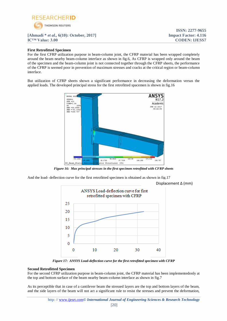
And the load- deflection curve for the first retrofitted specimen is obtained as shown in fig.17
Figure 17: ANSYS Load-deflection curve for the first retrofitted specimen with CFRP
Second Retrofitted Specimen
For the second CFRP utilization purpose in beam-column joint, the CFRP material has been implementedonly at
the top and bottom surface of the beam nearby beam-column interface as shown in fig.7
As its perceptible that in case of a cantilever beam the stressed layers are the top and bottom layers of the beam,
and the side layers of the beam will not act a significant rule to resist the stresses and prevent the deformation,
Displacement ∆ (mm)

ISSN: 2277-9655
[Ahmadi * et al., 6(10): October, 2017] Impact Factor: 4.116
IC™ Value: 3.00 CODEN: IJESS7
http: // www.ijesrt.com© International Journal of Engineering Sciences & Research Technology
[21]
hence in this case it has been also observed that no much difference is comprehensible between the first and
second retrofired specimens. The load-deflection curve for the second retrofitted specimen is shown in fig.18
Figure 18: Load-Deflection curve for the second retrofitted specimen with CFRP
Third Retrofitted Specimen
As bonding and debonding in employing of the CFRP sheets for enhancing the seismically performance of the
structures has been discussed as an importantpoint to be cared many researches, while the sheets are going to be
utilized. In this research for the third retrofitted specimen another logical CFRP wrapping configuration is
considered to be useful for prevention of debonding between the concrete and CFRP sheets. A grooving at the
column surface is provide by a depth of column concrete cover and the CFRP material is injected into that
groove, and bonded. This technique is also more conventional to be employed in practical, and it is expected
that this wrapping configuration shows a better performance due to its fixating technique. The third retrofired
specimen is shown in fig.8
In the third retrofitted configuration analyses, it has been observed that for the same loading condition, the
maximum principal stresses with a lower magnitude are concentrated at a point further the beam-column
intersection as Shown in fig.19
Figure 19: Max principal stresses in third retrofitted specimen with CFRP sheets

ISSN: 2277-9655
[Ahmadi * et al., 6(10): October, 2017] Impact Factor: 4.116
IC™ Value: 3.00 CODEN: IJESS7
http: // www.ijesrt.com© International Journal of Engineering Sciences & Research Technology
[22]
Figure 20: ANSYS Load-deflection curve for third retrofitted specimen with CFRP
Fourth Retrofitted Specimen
For the fourth CFRP utilization purpose in beam-column joint, the CFRP material has been implemented at the
top and bottom surface of the beam as well as, at the column surface nearby beam-column interface as shown in
fig.9.In this type of CFRP implemented configuration more surface of the specimen is covered by CFRP sheets,
to provide more interaction surface between the concrete and the CFRP sheets. And also a better connection is
provided between beam and column through the CFRP sheets that can be predicted as a logical advantage and
significance of this wrapping scheme. Hence the fourth retrofitted specimen has been designed based on this
logic to find out a configuration with a superb performance to show less deformation and, to control the
maximum principal stress concentration point at the beam-column joint. In the fourth retrofitted specimen due to
more surface of interaction that is provided between the CFRP sheets and concrete, it has been observed that
totally the principal stresses are distributed in a huge surface area, and this wrapping configuration seemed able
to contribute in distribution of stresses. This CFRP wrapping configuration seemed to be able to consolidate the
beam with column rather than all other retrofitted specimens.
The maximum stress concentration point also has been observed far away from the column face toward the
beam by an approximate distance of 500 mm, that technically it is possible toclaim that this wrapping scheme
exposed a better ability to relocate the plastic hinge from the column surface or the critical region toward the
beam.
Fig.21shows the maximum principal stress concentration point in fourth retrofitted specimen.

ISSN: 2277-9655
[Ahmadi * et al., 6(10): October, 2017] Impact Factor: 4.116
IC™ Value: 3.00 CODEN: IJESS7
http: // www.ijesrt.com© International Journal of Engineering Sciences & Research Technology
[23]
Figure 21: Max principal stresses in fourth retrofitted specimen with CFRP sheets
The load- deflection-curve that is obtained for the fourth specimen by ANSYS 17.2 in this study is shown in
fig.22
Figure 22: Load-deflection curve for the fourth retrofitted specimen with CFRP
After observation and individually discussion on every and each of the specimens that has been analyzed, now it
is time to generalize and conclude the research results by comparing of all load-deflection values, that its
graphical representation is shown in fig. 23

ISSN: 2277-9655
[Ahmadi * et al., 6(10): October, 2017] Impact Factor: 4.116
IC™ Value: 3.00 CODEN: IJESS7
http: // www.ijesrt.com© International Journal of Engineering Sciences & Research Technology
[24]
Figure23: Load-deflection curve for all specimens by ANSYS 17.2
From the above all represented results it can be observed that the first and second design by a maximum
deflection of 32.9672 mm and 29.9011 mm respectively, has shown a 15.44% and 23.29% increment in load
carrying capacity of the retrofitted specimen compared to control specimen (CSM0). Hence it can be concluded
that whilst the first and second retrofitted design has shown a disability to relocate the plastic, also showed a
poor capability of enhancing the load carrying capacity of the retrofitted specimens.
In the third design that the column face was grooved by a distance of column cover and the CFRP was injected
into the column face and bonded, for the applied load of 20 KN the maximum deflection has been observed to
be 19.329 mm, that compared to control specimen (CSM0) it has shown a 50.4%. increment in load carrying
capacity of the retrofitted specimen. Hence it can be concluded that despite the third design has shown a
satisfactory plastic hinge relocating capability, it also has shown a superb ability to enhance the load carrying
capacity of the specimen.
In the fourth design it has been observed that this type of CFRP wrapping also exposed a liable performance to
relocate the plastic hinge away from the column face toward the beam. And due to a huge surface of interaction
between the CFRP sheets and concrete surface it has been observed that the stresses were spread. In this design
the maximum deflection for the maximum applied force of 20 kN has been observed to be 23.6823 mm,
indicates an increment of 39.25% in load carrying capacity of the fourth design compared to control specimen.
VIII. CONCLUSIONS It has been observed that, due to the interface failure the first and second retrofitting schemes has
shown a poor performance in relocating of the plastic hinge. Though they have shown 15.43% and
23.29 % increment in load carrying capacity but, totally their performance can be mentioned
unsatisfactory.
The third and fourth design indicated the capability of externally bonded FRP laminates in relocating
the plastic hinge away from the column face, and also they have shown a good capability of enhancing
the load carrying capacity up to 50.4% and 39.25% respectively, hence the third and the fourth design
can be mentioned as ideal retrofitting schemes that, could also prevent the brittle joint shear failure
All strengthening configurations showed a significant increase in the ultimate strength of the joint. The
highest value (almost 50.4%) was observed in the third design. And in this retrofitted design the
interface failure was prevented through the insertion of FRP laminates in the concrete cover of the
column, but in utilizing of this retrofitting design, care should be taken to bond the FRP laminates
properly to prevent sudden debonding.
Nonlinear FE outcomes confirmed the reliability of the adopted FE model in predicting the seismic
behavior and load carrying capacity of RC structures, especially for retrofitting purposes. While the
results are reliable and justifiable, more studies have to be conducted on the FRP retrofitting of code-
compliant RC joint in order to quantify the increase in both strength and/or ductility and to formulate a
design approach

ISSN: 2277-9655
[Ahmadi * et al., 6(10): October, 2017] Impact Factor: 4.116
IC™ Value: 3.00 CODEN: IJESS7
http: // www.ijesrt.com© International Journal of Engineering Sciences & Research Technology
[25]
IX. REFERENCES [1] ACI 318-08, “Building Code Requirements for Structural Concrete and Commentary” American
Concrete Institute, Farmington Hills, MI, 2008.
[2] Akguzel, U., and Pampanin, S. (2012). Assessment and Design Procedure for the Seismic Retrofit of
Reinforced Concrete Beam-Column Joints using FRP Composite Materials. Journal of Composites for
Construction, ASCE, 16(1), 21-34.
[3] Alsayed, S.H., Al-Salloum, Y.A., Almusallam, T.H., and Siddiqui, N.A. (2010). SeismicResponse of
FRP-Upgraded Exterior RC Beam-Column Joints. Journal of Composites for Construction, ASCE,
14(2), 195-208.
[4] Antonopoulos, C.P., and Triantafillou, T.C. (2003). Experimental Investigation of FRP Strengthened
RC Beam-Column Joints. Journal of Composites for Construction, ASCE, 7(1), 39-49.
[5] ANSYS Mechanical Apdl Manual Set, (2012), Release 14.5, Ansys, Inc., USA, South point.
[6] Bousselham, A. (2010). State of Research on Seismic Retrofit of RC Beam-Column Joints with
Externally Bonded FRP. Journal of Composites for Construction, ASCE, 14(1), 4961.
[7] El-Amoury, T., and Ghobarah, A. (2002). Seismic Rehabilitation of Beam-Column Joint using
GFRP Sheets. Engineering Structures: The Journal of Earthquake, Wind and Ocean Engineering,
24(11), 1397-1407.
[8] FIB Bulletin No. 14, “Externally Bonded FRP Reinforcement for RC Structures”,
[9] Gergely, J., Pantelides, C.P., and Reaveley, L.D. (2000). Shear Strengthening of RCTJoints using
CFRP Composites. Journal of Composites for Construction, ASCE, 4(2), 56-64.
[10] Hegger, J., Sherif, A., and Roeser, W. (2004). Nonlinear Finite Element Analysis of Reinforced
Concrete Beam-Column Connections. ACI Structural Journal, 101(5), 604-614.
[11] H. Baji, A. Eslami, H.R. Ronagh, “Development of a nonlinear FE modelling approach for FRP-
strengthened RC beam-column connections” ISTRUC-00042; No of Pages 10
[12] IS 456: 2000 (Fourth Revision), “Indian Standard: Plain and Reinforced Concrete – Code of Practice”,
Bureau of Indian Standards, New Delhi, 2005.
[13] Lee, W.T., Chiou, Y.J., and Shih, M.H. (2010). Reinforced Concrete Beam–Column Joint Strengthened
with Carbon Fiber Reinforced Polymer. Composite Structures, 92, 48-60.
[14] Li, B., and Chua, H.Y.G. (2009). Seismic Performance of Strengthened Reinforced Concrete Beam-
Column Joints Using FRP Composites. Journal of Structural Engineering, ASCE, 135(10), 1177-1190.
[15] Mahini, S.S., and Ronagh, H.R. (2010). Strength and Ductility of FRP Web-Bonded RC Beams for the
Assessment of Retrofitted Beam–Column Joints. Composite Structures, 92, 1325-1332.
[16] Mahini, S.S., Isfahani, A.D., and Ronagh, H.R. (2008). Numerical Modelling of CFRP Retrofitted RC
Exterior Beam Column Joints under Cyclic Loads. Fourth International Conference on FRP
Composites in Civil Engineering, Zurich, Switzerland.
[17] Mahini, S.S., and Ronagh, H.R. (2011). Web-bonded FRPs for Relocation of Plastic Hinges Away
from the column face in exterior RC Joints. Composite Structures 93 (2011) 2460–2472
[18] Mahini SS, Ronagh HR, “Web-bonded FRPs for relocation of plastic hinges away from the column
face in exterior RC joints” Compos Struct2011; 93:2460 72
[19] Pankaj Agarwal, Manish shrikhande, “Earthquake Resistant Design of structures” (Reference Book)
CITE AN ARTICLE
Ahmadi, N., & Kodag, P. B. (2017). PLASTIC HINGE REPLACEMENT AND ENHANCING
THE LOAD CARRYING CAPACITY OF THE RC JOINTS USING
CFRP. INTERNATIONAL JOURNAL OF ENGINEERING SCIENCES & RESEARCH
TECHNOLOGY, 6(10), 9-25.