issues concerning the simulation of finishing wooden
TRANSCRIPT

261
NATURAL RESOURCES AND SUSTAINABLE DEVELOPMENT, 2013
ISSUES CONCERNING THE SIMULATION OF FINISHING WOODEN SCULPTURAL SURFACES IN THE CONCEPT OF FIVE
SIMULTANEOUS CNC AXES
Derecichei Laura*, Lucaci Codruta*, Ganea Macedon**
*University of Oradea, Faculty of Environmental Protection, 26 Gen. Magheru St., 410048 Oradea, Romania, e-mail: [email protected]
**University of Oradea, Faculty of Managerial and Technological Engineering, 1 University St., Oradea, 410087, Romania
Abstract The results of the simulation of the finishing operation were performed by the program SprutCam, which was obtained from the Faculty of Engineering "Hermann Oberth", Sibiu in the DEPARTMENT OF INDUSTRIAL MACHINERY AND EQUIPMENT, and the simulations were performed under the careful guidance of Prof. PhD. Eng. Radu Breaz from the „Lucian Blaga” University of Sibiu. The first operation is the import of the model in “igs” (.stl) format. The model called "panda.stl" will be selected. The program allows the modification of the existing post-processor or the development of a new post-processor for any type of CNC equipment . The NC code will appear in the window and will also be saved in a file with specific extension for each type of equipment, hereby exemplifying a small part of the code. Key words: wooden sculptural surfaces, 5-axes CNC, 3D model, finishing, woodworking
INTRODUCTION An important branch of CAM methods is the numeric control. This is a technique in which by means of some program instructions, the operations performed by the machine like: cutting, milling, drilling, turning of various areas of the semi-fabricates piece, can be controlled, so that at the end of the program to be possible to obtain the desired piece (Ganea, 2010, Curila S. et all, 2008, Curila et al., 2008). The first information about the use of CNC woodworking tools machine is taken from the HZB magazine (Jain, 1989), magazine which presents a review of an essay (Yoshimi, 2008, Marciniak, 1991), with the following mentions:
The motivation for introducing the CNC woodworking art is due mainly to the software evolution in the wood domain;
CN-Software differentiating as opposed to metal processing, area in which the CNC technique was introduced faster/ sooner (Racasan, 2011).
The processing in curved level type of a model’s surfaces. The milling processing is realised by moving the milling tool sucessively in a horizontal plane. The operation gives good results when the main areas of the processed model are close to vertical. To finish highly complex models it is recommended that after finishing by "Waterline" to use other finishing strategies (Ganea, 2010; Derecichei, 2013). Products CAD / CAM offers the possibility to prepare programs for processing equipment on the market. These software packages allow the next generation tool center trajectory and complex simulation of the machining process can be tracked movements of the moving parts of the machine required in the manufacturing process ( Ganea, 2007).

262
MATERIAL AND METHODS The results of the simulation of the finishing operation were performed by the program SprutCam, which was obtained from the Faculty of Engineering "Hermann Oberth", Sibiu in the DEPARTMENT OF INDUSTRIAL MACHINERY AND EQUIPMENT, and the simulations were performed under the careful guidance of Prof. PhD. Eng. Radu Breaz from the „Lucian Blaga” University of Sibiu (Derecichei, 2014). SprutCAM can generate programs for milling tools machines (CNC processing centers with up to 5 numerically controlled axes - three translational axes and two rotary axes)(www.sprutcam.com//geometricalmodel,2014;www.sprutcam.com/machiningmethods, 2014;www.sprutcam.com/technological-machining,2014). The SprutCAM program can be used in applications like: - Processing of parts with complex shapes; - Rapid Prototyping type processing; - Processing of pieces of the wood-working industry and wooden musical instruments and many more (www.sprutcam.com/sprutcam-and-solutions/purpose,2014; www.sprutcam.com,2014). The first operation is the import of the model in “igs” (.stl) format. The model called "panda.stl" will be selected. After importing, on the screen, the next image like in figure 1 should be displayed on the screen (Derecichei, Lucaci 2013; Derecichei, Lucaci, Galis 2013 ).
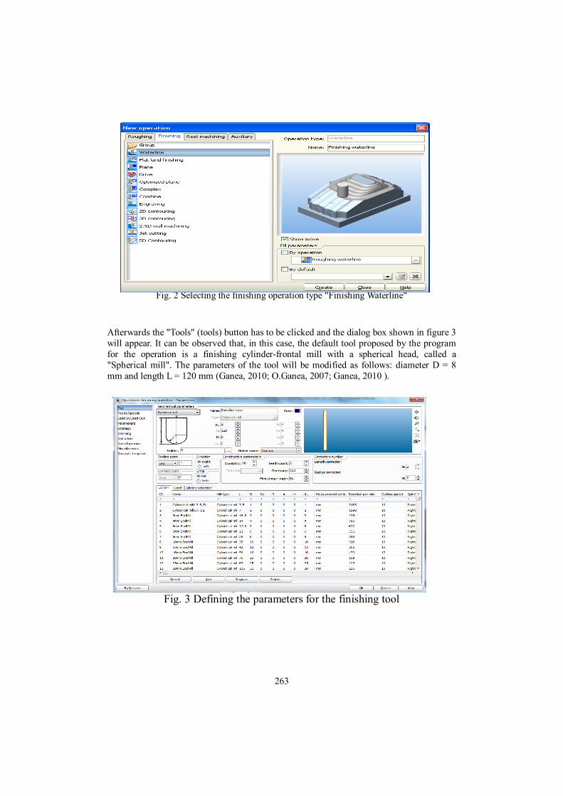
Fig. 1 The geometrical model After the roughing operation of the type level curve, "Waterline roughing", the finishing operation "Waterline" will be further defined, according to figure 2. After selecting the strategy, the „OK” button has to be clicked (Ganea,2010).
263
Fig. 2 Selecting the finishing operation type "Finishing Waterline" Afterwards the "Tools" (tools) button has to be clicked and the dialog box shown in figure 3 will appear. It can be observed that, in this case, the default tool proposed by the program for the operation is a finishing cylinder-frontal mill with a spherical head, called a "Spherical mill". The parameters of the tool will be modified as follows: diameter D = 8 mm and length L = 120 mm (Ganea, 2010; O.Ganea, 2007; Ganea, 2010 ).
Fig. 3 Defining the parameters for the finishing tool

264
Next comes the defining of the splitting regime’s parameters, stage which is illustrated in figure 4. To perform this exercise the default parameters proposed by the program can be left unmodified: splitting speed of 5.027 m/min, which will lead to an engine speed of 200 rev / min and an advance speed of 200 mm/min (Ganea M., Ganea C., 2000; Ganea M., 2010).
Fig. 4 Parameters of the finishing splitting regime
RESULTS AND DISCUSSION The situation before and after running the simulation is presented in the Figure 5. The symbol type "check mark" which confirms that the processing is conducted without collisions may be seen on the screen (Derecichei, Galis, 2013).
Fig. 5 The trajectory of the tool at the finishing operation The images displayed on the screen after running the simulations of the finishing process are presented in the Figures 6, 7, 8 and 9. The simulation allows various viewing types, and also the modification of the tools’ trajectory, respectively the intervention in the NC program (Derecichei, 2013; Lustun, Galiş, Lucaci, Derecichei, Nistor, 2012).

265
Fig. 6 The piece after the simulation of the finishing operation
Fig. 7 The piece after the simulation of the finishing operation

266
Fig. 8 The piece after the simulation of the finishing operation
Fig. 9 The piece after the simulation of the finishing operation
To generate the NC program it will be needed to return to the "Machining" menu and to click the "Postprocessor" button. As a result to this, a window called "NC-generation software" will be opened. From this window you can select the type of the device and the file name in which you want to save the generated NC program. After that the "Run" button has to be clicked to launch the generated NC program in execution. (http://www.sprutcam.com/2014).

267
In figure 10, the NC code generated for a Fanuc (30i)_Mill equipment is presented (www.gefanuc.com, 2014).
Fig. 10 Generating the NC program for a Fanuc (30i)_Mill equipment
Fig. 11 The editing and generating module for post-processors
The program allows the modification of the existing post-processor or the development of a new post-processor for any type of CNC equipment (Figure 11) (Derecichei, 2014; http://www.sprutcam.com, 2014) . The NC code will appear in the window and will also be saved in a file with specific extension for each type of equipment, hereby exemplifying a small part of the code (http://www.sprutcam.com, 2014).

268
PANDA ( GENERATED BY SprutCAM ) ( DATE: 04.03.2014 ) ..................................................... ( TOOLS LIST ) ( T1 CYLINDRICAL_MILL D20 ) ( T2 SPHERICAL_MILL D8 ) ( T3 SPHERICAL_MILL D30 ) ( FINISHING WATERLINE ) G53Z0. G53X0.Y0. T2M6 (8MM BALL NOSE) G02X-37.055Y13.143I-2.775J-2.455 X-37.984Y9.734I-7.342J0.171 .................................................... ( 5 AXES MULTI SURFACE ) G53Z0. G53X0.Y0. T3M6 (30MM BALL NOSE) G54 G68.2X0.Y0.Z0.I0.J0.K360. G53.1 S200M3 G00G43H3X-121.993Y47.335Z131.041B-18.989C-75.952 X-79.279Z6.912 Z-3.088 M8 G01Z-13.088F200 X-81.191Y47.382Z-13.743B-19.016C-73.65 X-81.983Y47.377Z-14.016B-18.989C-72.497 .......................................................................... X-85.455Y47.163Z-15.208B-18.955C-67.868 X-86.393Y47.061Z-15.531B-18.964C-66.71 ......................................................................... (http://www.sprutcam.com/sprutcam-andsolutions/sprutcam/postprocessors) CONCLUSIONS The processing of a complex piece on a numerically controlled tool machine (CNC) involves the generation of the NC code which contains, in a numerically coded form, the commands for the shifting of the machine’s slates and / or of the necessary tools to obtain the form of the finished piece. To generate the NC program it will be needed to return to the "Machining" menu and to click the "Postprocessor" button. As a result to this, a window called "NC-generation software" will be opened. From this window you can select the type of the device and the file name in which you want to save the generated NC program. After that the "Run" button has to be clicked to launch the generated NC program in execution. The NC code generated for a Fanuc (30i)_Mill equipment is presented. The simulation allows various viewing types, and also the modification of the tools’ trajectory, respectively the intervention in the NC program.

269
REFERENCES
Curilă Sorin, Cornelia E. Gordan, Mircea Curilă, “Tracking of polyhedral objects in image sequences”, 2008 IEEE 4th International Conference on Intelligent Computer Communication and Processing (ICCP 2008), August 28-30, 2008, Cluj-Napoca, Romania, Page(s):61 – 66, ISBN: 978-1-4244-2673-7;
Curilă Mircea , Sorin Curilă, “Geometry Compression of 3D Mesh utilizing Robust Second Order Blind Identification Algorithm”, Studies in Informatics and Control with Emphasis on Useful Applications of Advanced Technology, December 2008, volume 17, number 4, Edited by National Institute for R&D in Informatics ICI Bucharest, Page(s):421 – 434, ISSN 1220-1766.
Derecichei Laura, Lucaci Codruţa – 2013 - CAD-CAM software problem when drawing three-dimensional sculptures surfaces - International Sympozium “Risk Factors for Environment and Food Safety”, Annals of University of Oradea, Fascicle Environmental Protection vol.XXI year 18, University of Oradea 2013;
Derecichei Laura, Lucaci Codruţa, Galis Ioan – 2013 - Technological aspects of sculptural surface treatment of wood milling cutter or THOR - International Sympozium “Risk Factors for Environment and Food Safety”, Annals of University of Oradea, Fascicle Environmental Protection vol.XXI year 18, University of Oradea 2013;
Derecichei Laura, Galis Ioan – 2013 - LASER scanning sculptural surfaces - International Sympozium “Risk Factors for Environment and Food Safety”, Annals of University of Oradea, Fascicle Environmental Protection vol.XXI year 18, University of Oradea 2013;
Derecichei Laura - Research Report no. 1 - Current state of research and achievements in the field of wood processing complex surfaces, Univ. Oradea, Fac. IMT, February 2013;
Derecichei Laura - Research Report no. 3 - Achievements experimental sculptural wooden surfaces in concept 5-axis simultaneous CNC, Univ. Oradea, Fac. IMT, February 2014;
Ganea, M.- Flexible Machine Tools and Systems, ISBN 978-606-10-0020-3, University of Oradea Publishing House, 2010;
Ganea, M. - Machinery and Technology for Processing Surface Echipamenre 4 and 5 Axis CNC, ISBN 978-606-10-0041-8, University of Oradea Publishing House, 2010;
O. GANEA - Exam no. 3 in the doctoral training - Material Summary :: Vehicles and Equip. Technology for 5-axis CNC processing. Elem. of artificial intelligence. in Robotics, Univ. Oradea, Fac. IMT, June 2007;
Ganea M. -Flexible machine tools and technological equipment for machining prismatic parts”,Vol. 2: Cells and modules production equipment and flexible systems. Quality and reception CNC machine tools, University of Oradea Publishing House, ISBN 978-606-10-0339-6– 2010;
Ganea, M. s.a. - Constructive and technological objectives of the resources flow (working parts, tools, programs) at the flexible manufacturing cell; TMA AL 550, Scientific Session University of Oradea, 2010;
Ganea M., Ganea C. - Curved surfaces Spatial Processing Technology, University of Oradea, ISBN 973-8083-95-8, 2000;
Jain, A. K.: Fundamentals of Digital Image Processing, Prentice Hall, Englewood Cliffs NJ, 1989;
Lustun Liana Marta, Galiş Ioan, Lucaci Codruta, Derecichei Laura, Nistor Andrei

270
– 2012 - Peculiarities of Computer Programs CNC Multi Spindle Machining - International Sympozium “Risk Factors for Environment and Food Safety”, Annals of University of Oradea, Fascicle Environmental Protection, vol XIX, Year 17, University of Oradea 2012;
Marciniak, K. - Geometric modeling for numerically controlled machinig, Oxford University Press, 1991;
Racasan Sergiu – Contributions to optimize machining wood milled on CNC machining centers [CPCN] - Thesis, Transilvania University of Brasov, Brasov, 2011;
Yoshimi, I., Modular design for machine tools. MCGraw Hill Companies, SUA, 2008, ISBN 978-0-07-149660-5;
www.gefanuc.com; http://www.sprutcam.com/sprutcam-and-solutions/sprutcam/geometrical-
model,2014 http://www.sprutcam.com/sprutcam-and-solutions/sprutcam/machining-
methods,2014 http://www.sprutcam.com/sprutcam-and-solutions/sprutcam/technological-
machining ,2014 http://www.sprutcam.com/sprutcam-and-solutions/sprutcam/purpose,2014 http://www.sprutcam.com/sprutcam-and-solutions/sprutcam/postprocessors,2014 http://www.sprutcam.com, 2014