istituto nazionale di fisica nucleare sezione di genova
TRANSCRIPT
ISTITUTO NAZIONALE DI FISICA NUCLEARE
Sezione di Genova
INFN/BE-07/018 Giugno 2007
SOLENOID MAGNET AND FLUX RETURN FOR THE PANDA DETECTOR
Andrea Bersani1, Renzo Parodi1, Andrea Pastorino1,1) INFN, Sezione di Genova, Dip. di Fisica, Univ. di Genova, I-16146 Genova, Italy
Abstract
In this paper we present the project of the Solenoid Magnet for the PANDA detec-tor developed in Genova. This project features a coil realized with a Rutherford–type,aluminum stabilized superconducting cable, wound inside an aluminum alloy coil formerand indirectly cooled with a forced circulation of liquid helium. The concept of this mag-net is based on many other working magnets, developed for different detectors, such asBaBar, Finuda, Delphi or CMS. A complete characterization of the magnetic, mechanicaland thermal properties of the magnet is presented, with an ansatz on the time schedule tobe followed to fulfill the detector deadlines.
PACS: 07.55.Db; 84.71.Ba; 29.30.-h; 29.30.Ep
Published by SIS-PubblicazioniLaboratori Nazionali di Frascati
The PANDA[1] experiment is a4π, high resolution spectrometer for low energy
particle physics, mainly devoted to the study of QCD and related matters, using an an-
tiproton beam colliding on an internal hydrogen target. Thedetector is formed by a barrel
section, surrounding the interaction region, and a dipole section, used for the detection of
the low-angle particles. We present a project of the solenoid for the barrel section: this
project was developed to fulfill all the requirements comingfrom the detector people and
was optimized in tight collaboration with the GSI technicalexperts. Even if the magnet
concept is quite conventional, the geometrical constraints required a very important effort
to be fulfilled simultaneously with the magnetic ones.
1 Physics Requirements and Performance Goals
The PANDA target magnet is a thin, superconducting solenoid with an octagonal flux
return yoke, as shown in fig. 1. Detector performance criteria and geometry considera-
tions drive the design of the solenoid and the flux return. Themagnitude and uniformity
specifications for the magnetic field are derived from the tracker requirements: to achieve
a mass resolution of the order of10 MeV a magnetic field of2 T is needed. The combined
thickness of the vertex detector, outer tracker, particle identification system, electromag-
netic calorimeter and appropriate clearences sets the cryostat inner diameter. The cryostat
length is also constrained by the length of the nested subsystems and, critically, by the
clearance requirements for the end cap detectors and for theservicing. The solenoid
thickness has to be taken into account when evaluating the detection threshold of muons
in the chambers hosted inside and outside the flux return yoke.
The shape of the downstream region of the yoke has been designed to allow the
installation of several layers of muon chambers: a rough tracking of outgoing muons will
be achieved thanks to this superlayer of steel and sensitiveelements.
The minimum thickness in the barrel and in the end caps is calculated to avoid
magnetic saturation and to stop pions: this is evaluated∼ 40 cm. End caps segmentation
was studied to clamp the fringe fields without an eccessive increase of the amount of
steel involved. Separation and movement of the end doors areconstrained by beam line
components, by the presence of the dipole magnet in downstream direction and by the
need to provide ready access to detector subsystems.
The physics performance and operational requirements for the solenoid magnet and
for the flux return (tables 1 and 2) are similar to those of manyoperating detector magnets.
2
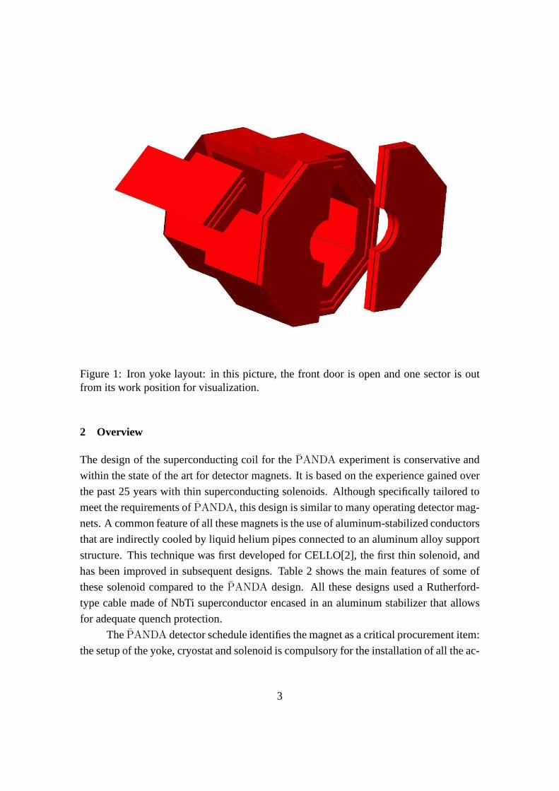
Figure 1: Iron yoke layout: in this picture, the front door isopen and one sector is outfrom its work position for visualization.
2 Overview
The design of the superconducting coil for thePANDA experiment is conservative and
within the state of the art for detector magnets. It is based on the experience gained over
the past 25 years with thin superconducting solenoids. Although specifically tailored to
meet the requirements ofPANDA, this design is similar to many operating detector mag-
nets. A common feature of all these magnets is the use of aluminum-stabilized conductors
that are indirectly cooled by liquid helium pipes connectedto an aluminum alloy support
structure. This technique was first developed for CELLO[2],the first thin solenoid, and
has been improved in subsequent designs. Table 2 shows the main features of some of
these solenoid compared to thePANDA design. All these designs used a Rutherford-
type cable made of NbTi superconductor encased in an aluminum stabilizer that allows
for adequate quench protection.
ThePANDA detector schedule identifies the magnet as a critical procurement item:
the setup of the yoke, cryostat and solenoid is compulsory for the installation of all the ac-
3
Solenoid RequirementsCentral induction 2 TUniformity in outer tracker ±2%Nuclear interaction length 0.4λint
Cryostat inner radius 950 mmCryostat outer radius 1340 mmMinimization of thermal cycling
Flux return RequirementsProvide an external path for the magnetic fieldProvide support and stopping for muon chambersProvide gravitational load for the detectorMovable end doors to allow access inside the barrel
Table 1: Physics performances and operational requirements for thePANDA solenoid.
tive parts of the detector. This is due to the fact that the cryostat itself provides mechanical
support for the various detectors: so, before the assembly,also tests and commissioning
of the magnet are needed. The solenoid design, fabrication and commissioning duration
foreseen is30 ÷ 36 months, so the contract should be awarded in the summer of 2008 to
meet the overall detector schedule.
The magnet cryostat will be designed, fabricated and inspected according to the
intent of the ASME Boiler and Pressure-Vessel Code, SectionVIII, Division 2 [3], but
will not be code-stamped. For steel structures, the allowable design stresses follow the
standard guidelines of European and Italian standards [4][5]. Bolted connections and
fasteners will conform to their recommended torques and allowable stresses depending
on the connection. The flux return is fabricated with S235 JR structural steel plates or a
material with similar mechanical and magnetic properties.
2.1 Descritpion of Key interfaces
Superconducting Solenoid and Flux Return.The radial distance between the outer diameter of the cryostat and the inner surface
of the barrel flux return is100 mm: in this space is foreseen a double layer of muon
detectors. The presence of muon chambers inside the barrel is compulsory to achieve a
sufficient tracking capability for low energy muons. The solenoid weigth and magnetic
forces are transmitted to the yoke by means of titanium and structural steel supports.
These attachments, providing also the load path for the inner detector components to the
4
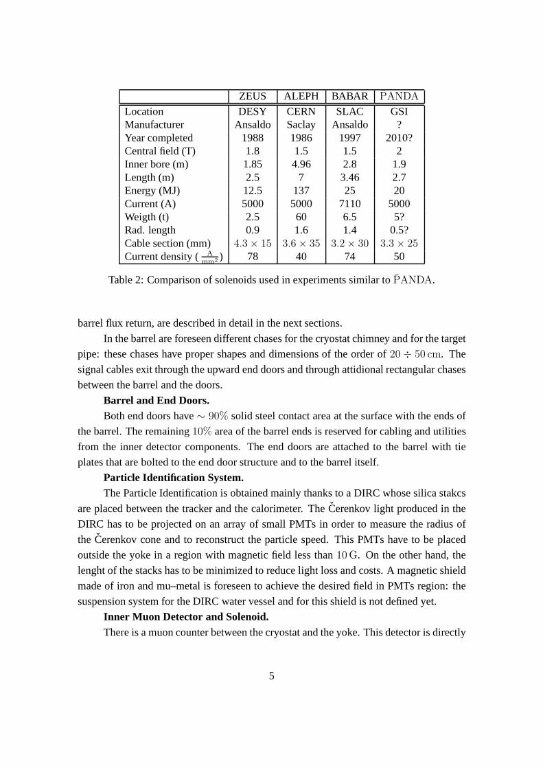
ZEUS ALEPH BABAR PANDA
Location DESY CERN SLAC GSIManufacturer Ansaldo Saclay Ansaldo ?Year completed 1988 1986 1997 2010?Central field (T) 1.8 1.5 1.5 2Inner bore (m) 1.85 4.96 2.8 1.9Length (m) 2.5 7 3.46 2.7Energy (MJ) 12.5 137 25 20Current (A) 5000 5000 7110 5000Weigth (t) 2.5 60 6.5 5?Rad. length 0.9 1.6 1.4 0.5?Cable section (mm) 4.3 × 15 3.6 × 35 3.2 × 30 3.3 × 25Current density ( A
mm2 ) 78 40 74 50
Table 2: Comparison of solenoids used in experiments similar to PANDA.
barrel flux return, are described in detail in the next sections.
In the barrel are foreseen different chases for the cryostatchimney and for the target
pipe: these chases have proper shapes and dimensions of the order of20 ÷ 50 cm. The
signal cables exit through the upward end doors and through attidional rectangular chases
between the barrel and the doors.
Barrel and End Doors.Both end doors have∼ 90% solid steel contact area at the surface with the ends of
the barrel. The remaining10% area of the barrel ends is reserved for cabling and utilities
from the inner detector components. The end doors are attached to the barrel with tie
plates that are bolted to the end door structure and to the barrel itself.
Particle Identification System.The Particle Identification is obtained mainly thanks to a DIRC whose silica stakcs
are placed between the tracker and the calorimeter. TheCerenkov light produced in the
DIRC has to be projected on an array of small PMTs in order to measure the radius of
the Cerenkov cone and to reconstruct the particle speed. This PMTs have to be placed
outside the yoke in a region with magnetic field less than10 G. On the other hand, the
lenght of the stacks has to be minimized to reduce light loss and costs. A magnetic shield
made of iron and mu–metal is foreseen to achieve the desired field in PMTs region: the
suspension system for the DIRC water vessel and for this shield is not defined yet.
Inner Muon Detector and Solenoid.There is a muon counter between the cryostat and the yoke. This detector is directly
5

Figure 2: Field uniformity inside the solenoid: in pink the outer tracker region (divisionis 1%).
attached to the barrel, and, with the microvertex detector,which is suspended to the beam
pipe, is the only one that doesn’t load the cryostat. Becauseof the presence of the cryostat
support, a proper design for the muon plates located inside the barrel is needed.
Movable End Door Skids and the Beam Line.The end doors are mounted on skids equipped with rollers so that they can be moved
away from the barrel for maintenance access. The end door skids move on tracks installed
in the floor. The end doors clear the beam line magnets, vacuumpumps, magnet stands,
and other beam line equipment during door opening.
External Platforms, Stairways, and Walkways.The external platforms necessary to install and service electronic racks and cryo-
genic equipment are supported from the flux return. The requirements of these compo-
nents have not yet been determined.
3 Summary of Projected Magnet Performance.
3.1 Central Field Magnitude and Coil Performance.
The magnetic field of2 T is obtained by energizing the solenoid with a constant current
of 5000 A. The conductor is operated at50% of the critical current, with a peak field in
the conductor of2.8 T. This gives a large safety margin.
Magnetic uniformity is achieved by using different currentdensities in regions at
both ends of the solenoid w.r.t. the central region. This is done by adding more aluminum
6
stabilizer to the central region conductor, which reduces the current density there. Fig.
2 shows the field uniformity in the central region. The areas in which the field nonuni-
formity is greater than1.5% are small and are located in regions in which they do not
affect the performance of the drift chamber. In addition, once the solenoid parameters are
optimized, the corners of the drift chamber are also within±2% of 2 T.
The radial pressure due to magnetic forces on the conductor during operation is
∼ 2.90 MPa in the high current density regions and∼ 1 MPa in the central region of the
conductor. An aluminum alloy support cylinder surrounds the coiled conductor to react
against these radial pressures and keep the conductor from yielding.
The integrated axial force on the winding is∼ 8 MN. The conductor winding and
support cylinder are mechanically coupled by an epoxy bond.This epoxy bond allows
some of the axial load to be transmitted in shear to the outer aluminum cylinder, which
keeps the conductor from yielding. There is an axial∼ 1 MN decentering force applied
to the conductor winding due to the asymmetry in the iron yoke.
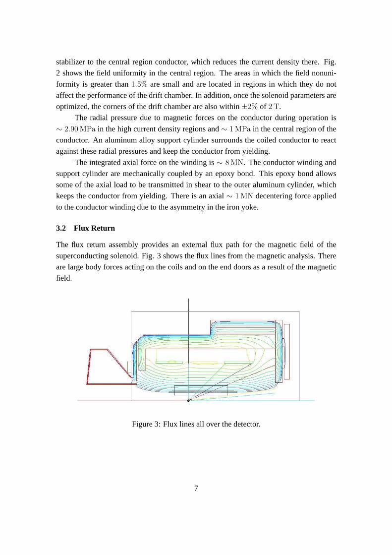
3.2 Flux Return
The flux return assembly provides an external flux path for themagnetic field of the
superconducting solenoid. Fig. 3 shows the flux lines from the magnetic analysis. There
are large body forces acting on the coils and on the end doors as a result of the magnetic
field.
Figure 3: Flux lines all over the detector.
7
4 Superconducting Solenoid
4.1 Magnetic Design
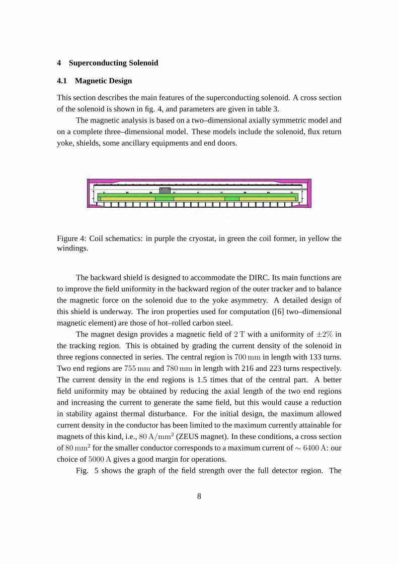
This section describes the main features of the superconducting solenoid. A cross section
of the solenoid is shown in fig. 4, and parameters are given in table 3.
The magnetic analysis is based on a two–dimensional axiallysymmetric model and
on a complete three–dimensional model. These models include the solenoid, flux return
yoke, shields, some ancillary equipments and end doors.
Figure 4: Coil schematics: in purple the cryostat, in green the coil former, in yellow thewindings.
The backward shield is designed to accommodate the DIRC. Itsmain functions are
to improve the field uniformity in the backward region of the outer tracker and to balance
the magnetic force on the solenoid due to the yoke asymmetry.A detailed design of
this shield is underway. The iron properties used for computation ([6] two–dimensional
magnetic element) are those of hot–rolled carbon steel.
The magnet design provides a magnetic field of2 T with a uniformity of±2% in
the tracking region. This is obtained by grading the currentdensity of the solenoid in
three regions connected in series. The central region is700 mm in length with 133 turns.
Two end regions are755 mm and780 mm in length with 216 and 223 turns respectively.
The current density in the end regions is 1.5 times that of thecentral part. A better
field uniformity may be obtained by reducing the axial lengthof the two end regions
and increasing the current to generate the same field, but this would cause a reduction
in stability against thermal disturbance. For the initial design, the maximum allowed
current density in the conductor has been limited to the maximum currently attainable for
magnets of this kind, i.e.,80 A/mm2 (ZEUS magnet). In these conditions, a cross section
of 80 mm2 for the smaller conductor corresponds to a maximum current of ∼ 6400 A: our
choice of5000 A gives a good margin for operations.
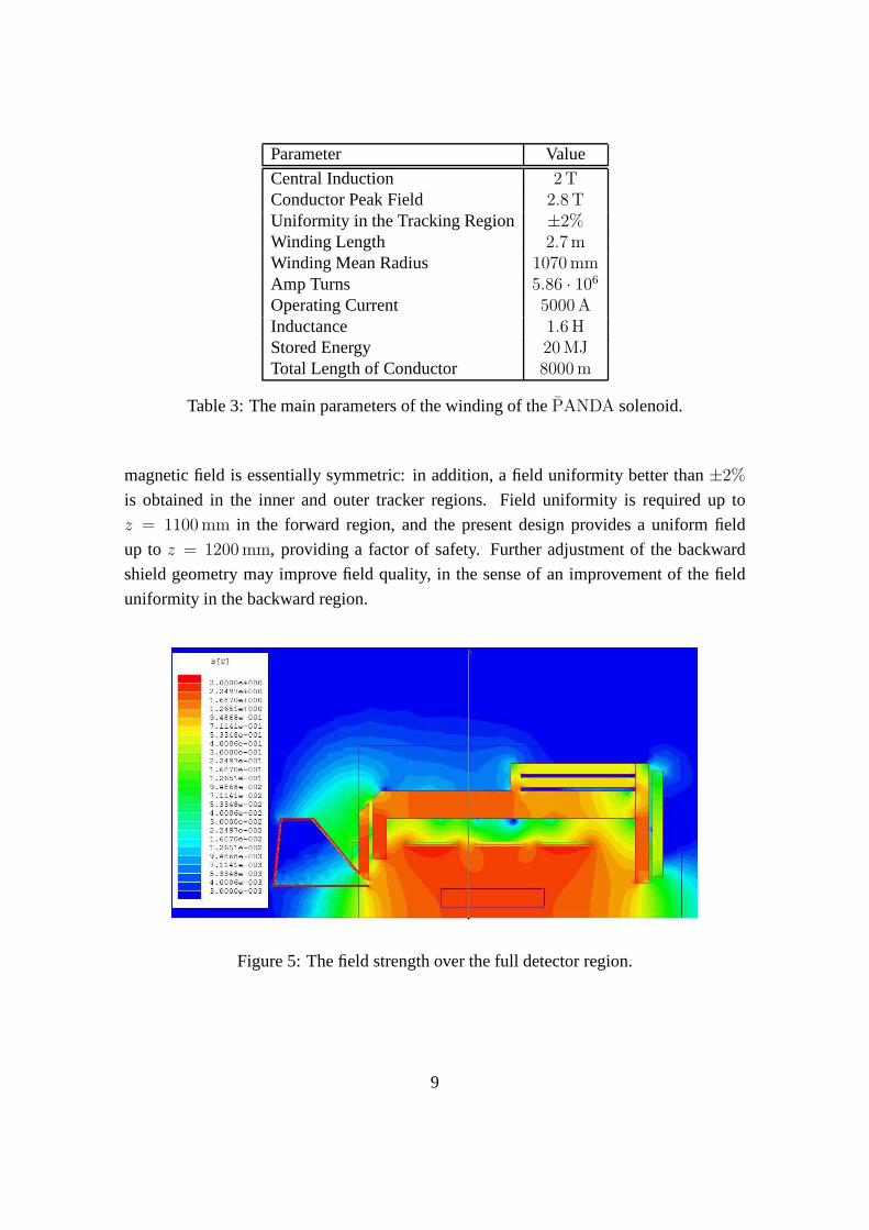
Fig. 5 shows the graph of the field strength over the full detector region. The
8
Parameter Value
Central Induction 2 TConductor Peak Field 2.8 TUniformity in the Tracking Region ±2%Winding Length 2.7 mWinding Mean Radius 1070 mmAmp Turns 5.86 · 106
Operating Current 5000 AInductance 1.6 HStored Energy 20 MJTotal Length of Conductor 8000 m
Table 3: The main parameters of the winding of thePANDA solenoid.
magnetic field is essentially symmetric: in addition, a fielduniformity better than±2%
is obtained in the inner and outer tracker regions. Field uniformity is required up to
z = 1100 mm in the forward region, and the present design provides a uniform field
up to z = 1200 mm, providing a factor of safety. Further adjustment of the backward
shield geometry may improve field quality, in the sense of an improvement of the field
uniformity in the backward region.
Figure 5: The field strength over the full detector region.
9
4.2 Cold Mass Design
Aluminum Stabilized ConductorThe conductor is composed of a superconducting Rutherford cable embedded in a
very pure aluminum matrix by a coextrusion process that ensures a good bond between
aluminum and superconductor. Table 4 shows the main parameters of the conductor.
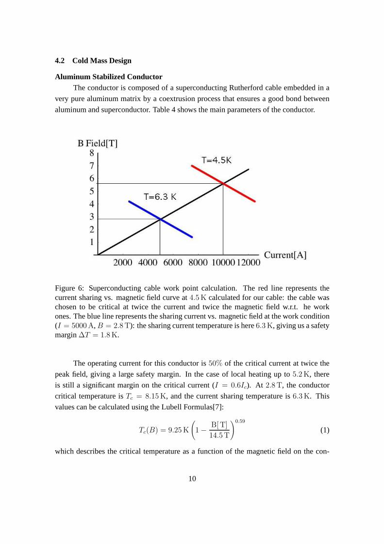
Figure 6: Superconducting cable work point calculation. The red line represents thecurrent sharing vs. magnetic field curve at4.5 K calculated for our cable: the cable waschosen to be critical at twice the current and twice the magnetic field w.r.t. he workones. The blue line represents the sharing current vs. magnetic field at the work condition(I = 5000 A, B = 2.8 T): the sharing current temperature is here6.3 K, giving us a safetymargin∆T = 1.8 K.
The operating current for this conductor is50% of the critical current at twice the
peak field, giving a large safety margin. In the case of local heating up to5.2 K, there
is still a significant margin on the critical current (I = 0.6Ic). At 2.8 T, the conductor
critical temperature isTc = 8.15 K, and the current sharing temperature is6.3 K. This
values can be calculated using the Lubell Formulas[7]:
Tc(B) = 9.25 K
(
1 −B[ T]
14.5 T
)0.59
(1)
which describes the critical temperature as a function of the magnetic field on the con-
10
ductor and
Jc(B) = J0
(
1 −T
Tc(B)
)
(2)
which describes the critical current density as a function of the magnetic field on the
conductor and of the temperature.
A simple method to evaluate the stability of the winding consists of considering
the enthalpy margin per unit length between the operating and the sharing temperature.
This stability parameter for thePANDA solenoid is 0.5 J/m, which is the same value
obtained for the ALEPH and BaBar magnets.
The cross section of the conductor is3.3 × 24.6 mm2 for the higher current density
regions and5.15 × 24.6 mm2 for the central region. The coil winding can be made using
six1500 m lengths of conductor, requiring five electrical joints. Each joint, made by either
by TIG welding (as in the Atlas barrel Toroid and CMS), or softsoldering (after electro–
deposition of copper) a suitable length of the aluminum matrix must have a resistance less
than5 · 10−10Ω, limiting the power dissipation to a few milliwatts.
Winding SupportThe winding will be supported by an external aluminum alloy cylinder similar to
other existing detector magnets. The winding support is designed for all aspects of force
containment, i.e., its weight and the radial and axial magnetic forces. Fig. 7 shows these
magnetic forces on the solenoid.
The maximum radial pressure,∼ 2.90 MPa, is generated in the high current density
regions at the ends of the coils. A pressure of∼ 1 MPa is generated in the central region.
An aluminum alloy (Al 5083 T0) support cylinder surrounds the coiled conductor to react
against these radial pressures and prevent coil movement. An extended stress analysis
of the solenoid coil-support cylinder assembly has been developed to investigate the be-
haviour of the high-ductility pure aluminium stabilizer and epoxy resin under the high
radial pressures generated by magnetic forces. The cable was thus simulated including
the material non-linear stress-strain curve. As a result, plastic deformations are expected
to occur in the coils during the first charge. The amount of these deformations is small
and ensures that the cable will not be stressed beyond the elastic limit in the subsequent
charges. This will help prevent premature quenching duringcoil energizing. Nevertheless,
the support cylinder is capable to contain the deformationsof the coils while remaining
in the elastic field.
An integrated compressive axial force of∼ 8 MN is induced in the winding. The
distribution of the axial force within the coil is complex. The central part is slightly
axially stressed by a force of less than1 MN. For preliminary calculations of the axial
stress, the maximum force was considered (4.3 MN in the worst case for one of the three
11
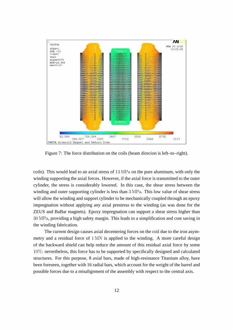
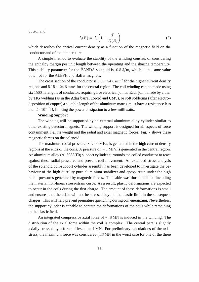
Figure 7: The force distribution on the coils (beam direcionis left–to–right).
coils). This would lead to an axial stress of13 MPa on the pure aluminum, with only the
winding supporting the axial forces. However, if the axial force is transmitted to the outer
cylinder, the stress is considerably lowered. In this case,the shear stress between the
winding and outer supporting cylinder is less than3 MPa. This low value of shear stress
will allow the winding and support cylinder to be mechanically coupled through an epoxy
impregnation without applying any axial prestress to the winding (as was done for the
ZEUS and BaBar magnets). Epoxy impregnation can support a shear stress higher than
30 MPa, providing a high safety margin. This leads to a simplification and cost saving in
the winding fabrication.
The current design causes axial decentering forces on the coil due to the iron asym-
metry and a residual force of1 MN is applied to the winding. A more careful design
of the backward shield can help reduce the amount of this residual axial force by some
10%: nevertheless, this force has to be supported by specifically designed and calculated
structures. For this purpose, 8 axial bars, made of high-resistance Titanium alloy, have
been foreseen, together with 16 radial bars, which account for the weight of the barrel and
possible forces due to a misalignment of the assembly with respect to the central axis.
12
Parameter Value
Conductor Type NbTiPure Al–stabilized
Co–extrudedAluminum RRR > 500Conductor Unit Length 1.5 kmNumber of Lengths 6Bare dimensions 3.3 and5.15 × 24.6 mm2
Insulated dimensions 3.7 and5.55 × 25 mm2
Superconducting Cable Rutherford typeDimensions 9 × 1.23 mm2
Strands Diameter 0.84 mmNumber of Strands 20Cu/Sc 1.8Filament Diameter 20 µmIc(B = 2.5 T, T = 4.5 K) > 10 kAInsulation Type Fiberglass TapeInsulation Thickness 0.4 mm
Table 4: Conductor parameters.
While the preliminary analyses described above decoupled the effects of radial and
axial magnetic forces on the coils and support cylinder, a comprehensive 3D FEM analysis
has been made simulating the coil and cylinder assembly under the effect of the magnetic
field during nominal operations. The results of this calculation (see Fig. 8), confirming
previous analyses, are pointed out below:
• The radial pressure generated in the windings causes the pure aluminium stabilizer
to exceed its elastic limit, showing permanent deformations after the first charge.
Nevertheless, the amount of the plastic deformations is negligible and stresses will
remain within the elastic range during the subsequent charges.
• The shear stress transmitted through the epoxy resin to the aluminium support cylin-
der is fairly low if compared to the resin capabilities.
• Stability of the whole assembly is ensured by the Al 5083 aluminium barrel. The
analysis show that the cylinder is capable to contain the radial and axial deforma-
tions of the windings without showing permanent deformations.
• Axial and radial supports have also been included in the model. The decentering
13
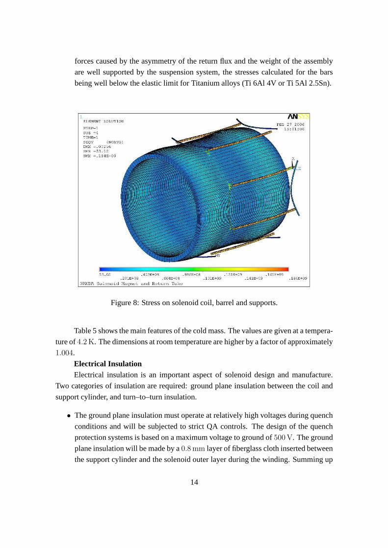
forces caused by the asymmetry of the return flux and the weight of the assembly
are well supported by the suspension system, the stresses calculated for the bars
being well below the elastic limit for Titanium alloys (Ti 6Al 4V or Ti 5Al 2.5Sn).
Figure 8: Stress on solenoid coil, barrel and supports.
Table 5 shows the main features of the cold mass. The values are given at a tempera-
ture of4.2 K. The dimensions at room temperature are higher by a factor ofapproximately
1.004.
Electrical InsulationElectrical insulation is an important aspect of solenoid design and manufacture.
Two categories of insulation are required: ground plane insulation between the coil and
support cylinder, and turn–to–turn insulation.
• The ground plane insulation must operate at relatively highvoltages during quench
conditions and will be subjected to strict QA controls. The design of the quench
protection systems is based on a maximum voltage to ground of500 V. The ground
plane insulation will be made by a0.8 mm layer of fiberglass cloth inserted between
the support cylinder and the solenoid outer layer during thewinding. Summing up
14
this insulation layer to the cable insulation we get a groundinsulation of∼ 1. mm
We are confident from the previous experience on similar solenoids (BaBaR, Zeus,
CMS) that this ground insulation thickness should be adequate to withstands the
quench voltage of∼ 500 V The insulation will be fully tested at2 kV along the
winding process. At the end of the ground plane insulation will be fully vacuum
impregnated with high strength epoxy resin.
• The conductor will be insulated with a double wrap of0.125 mm glass tape during
winding to give an insulation thickness of0.2 mm (80% compacted). The resulting
turn–to–turn insulation thickness will be0.4 mm and will be fully impregnated in
the bonding process. Electrical tests will be carried out during winding to detect
any failure of insulation. The tests will include regular/continuous testing for turn–
to–turn and turn–to–ground insulation.
4.3 Quench Protection and Stability
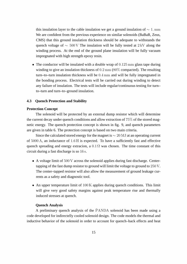
Protection ConceptThe solenoid will be protected by an external dump resistor which will determine
the current decay under quench conditions and allow extraction of 75% of the stored mag-
netic energy. The quench protection concept is shown in fig. 9, and quench parameters
are given in table 6. The protection concept is based on two main criteria.
Since the calculated stored energy for the magnet is∼ 20 MJ at an operating current
of 5000 A, an inductance of1.6 H is expected. To have a sufficiently fast and effective
quench spreading and energy extracion, a0.1 Ω was chosen. The time constant of this
circuit during a fast discharge is so16 s.
• A voltage limit of 500 V across the solenoid applies during fast discharge. Center-
tapping of the fast dump resistor to ground will limit the voltage to ground to250 V.
The center–tapped resistor will also allow the measurementof ground leakage cur-
rents as a safety and diagnostic tool.
• An upper temperature limit of100 K applies during quench conditions. This limit
will give very good safety margins against peak temperaturerise and thermally
induced stresses at quench.
Quench AnalysisA preliminary quench analysis of thePANDA solenoid has been made using a
code developed for indirectelly cooled solenoid design. The code models the thermal and
inductive behavior of the solenoid in order to account for quench–back effects and heat
15
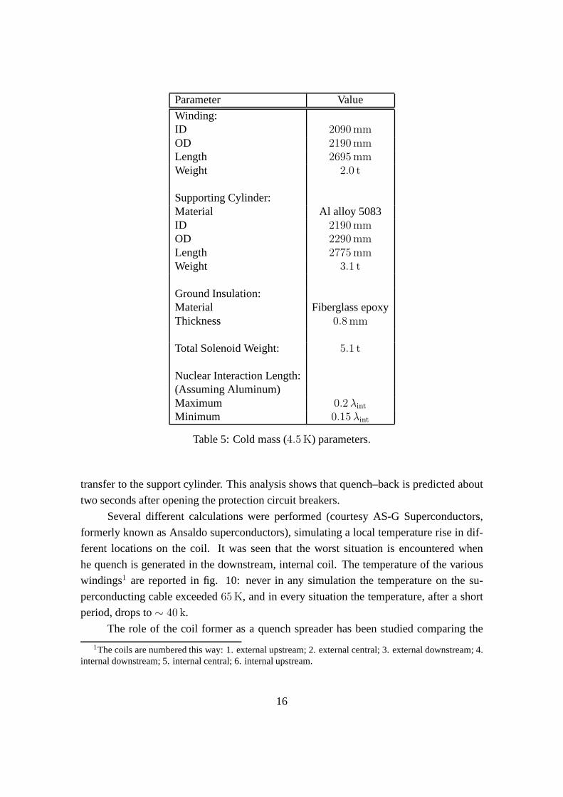
Parameter Value
Winding:ID 2090 mmOD 2190 mmLength 2695 mmWeight 2.0 t
Supporting Cylinder:Material Al alloy 5083ID 2190 mmOD 2290 mmLength 2775 mmWeight 3.1 t
Ground Insulation:Material Fiberglass epoxyThickness 0.8 mm
Total Solenoid Weight: 5.1 t
Nuclear Interaction Length:(Assuming Aluminum)Maximum 0.2 λint
Minimum 0.15 λint
Table 5: Cold mass (4.5 K) parameters.
transfer to the support cylinder. This analysis shows that quench–back is predicted about
two seconds after opening the protection circuit breakers.
Several different calculations were performed (courtesy AS-G Superconductors,
formerly known as Ansaldo superconductors), simulating a local temperature rise in dif-
ferent locations on the coil. It was seen that the worst situation is encountered when
he quench is generated in the downstream, internal coil. Thetemperature of the various
windings1 are reported in fig. 10: never in any simulation the temperature on the su-
perconducting cable exceeded65 K, and in every situation the temperature, after a short
period, drops to∼ 40 k.
The role of the coil former as a quench spreader has been studied comparing the
1The coils are numbered this way: 1. external upstream; 2. external central; 3. external downstream; 4.internal downstream; 5. internal central; 6. internal upstream.
16
Figure 9: Solenoid power and and quench protection concept.
temperature rise with and without the coil former itself: this case is similar to the one of a
coil former made of a poor heat and current conductor, such asstainless steel, carbon fibre
or similar. Even in this configuration, the quench remains limited to the coil in which is
started and in the closest one, and the temperature doesn’t exceeds80 K.
Fig. 11 shows the voltage a the ends of each winding and the current in the coil
after a quench: a time constant of∼ 16 s is otbained, confrming the value of inductance
of ∼ 1.6 H obtained from pure magnetic calculations.
StabilityThe PANDA solenoid coil will be indirectly cooled using the technology estab-
lished for existing detector magnets such as DELPHI and ALEPH. The reliable operation
of those magnets has demonstrated that safe stability margins can be achieved using high–
purity, aluminum–clad superconductors in a fully bonded, indirectly cooled coil structure.
Conductor stability has been estimated using an analysis code in order to establish
the minimum quench energy (MQE) for transient heat pulses. The computedMQE =
1.4 J. The computed minimum quench length (MQZ) is 0.6 m.
These margins are considered to be safe for thePANDA solenoid due to its low–
stress design. The stability margin will be optimized during the full design study.
17
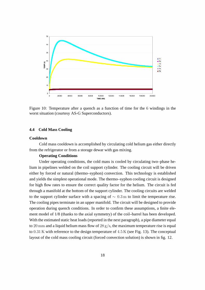
Figure 10: Temperature after a quench as a function of time for the 6 windings in theworst situation (courtesy AS-G Superconductors).
4.4 Cold Mass Cooling
CooldownCold mass cooldown is accomplished by circulating cold helium gas either directly
from the refrigerator or from a storage dewar with gas mixing.
Operating ConditionsUnder operating conditions, the cold mass is cooled by circulating two–phase he-
lium in pipelines welded on the coil support cylinder. The cooling circuit will be driven
either by forced or natural (thermo–syphon) convection. This technology is established
and yields the simplest operational mode. The thermo–syphon cooling circuit is designed
for high flow rates to ensure the correct quality factor for the helium. The circuit is fed
through a manifold at the bottom of the support cylinder. Thecooling circuits are welded
to the support cylinder surface with a spacing of∼ 0.3 m to limit the temperature rise.
The cooling pipes terminate in an upper manifold. The circuit will be designed to provide
operation during quench conditions. In order to confirm these assumptions, a finite ele-
ment model of 1/8 (thanks to the axial symmetry) of the coil–barrel has been developed.
With the estimated static heat loads (reported in the next paragraph), a pipe diameter equal
to 20 mm and a liquid helium mass flow of28 g/s, the maximum temperature rise is equal
to 0.31 K with reference to the design temperature of4.5 K (see Fig. 13). The conceptual
layout of the cold mass cooling circuit (forced convection solution) is shown in fig. 12.
18
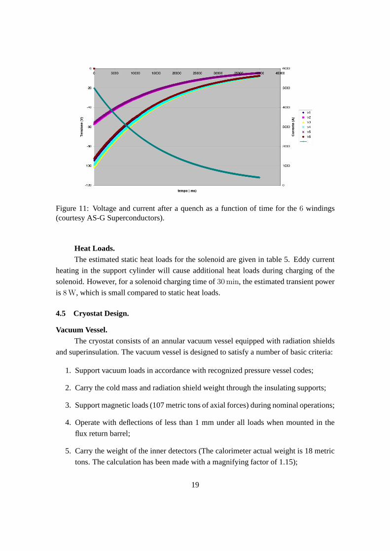
Figure 11: Voltage and current after a quench as a function oftime for the6 windings(courtesy AS-G Superconductors).
Heat Loads.The estimated static heat loads for the solenoid are given intable 5. Eddy current
heating in the support cylinder will cause additional heat loads during charging of the
solenoid. However, for a solenoid charging time of30 min, the estimated transient power
is 8 W, which is small compared to static heat loads.
4.5 Cryostat Design.
Vacuum Vessel.The cryostat consists of an annular vacuum vessel equipped with radiation shields
and superinsulation. The vacuum vessel is designed to satisfy a number of basic criteria:
1. Support vacuum loads in accordance with recognized pressure vessel codes;
2. Carry the cold mass and radiation shield weight through the insulating supports;
3. Support magnetic loads (107 metric tons of axial forces) during nominal operations;
4. Operate with deflections of less than 1 mm under all loads when mounted in the
flux return barrel;
5. Carry the weight of the inner detectors (The calorimeter actual weight is 18 metric
tons. The calculation has been made with a magnifying factorof 1.15);
19
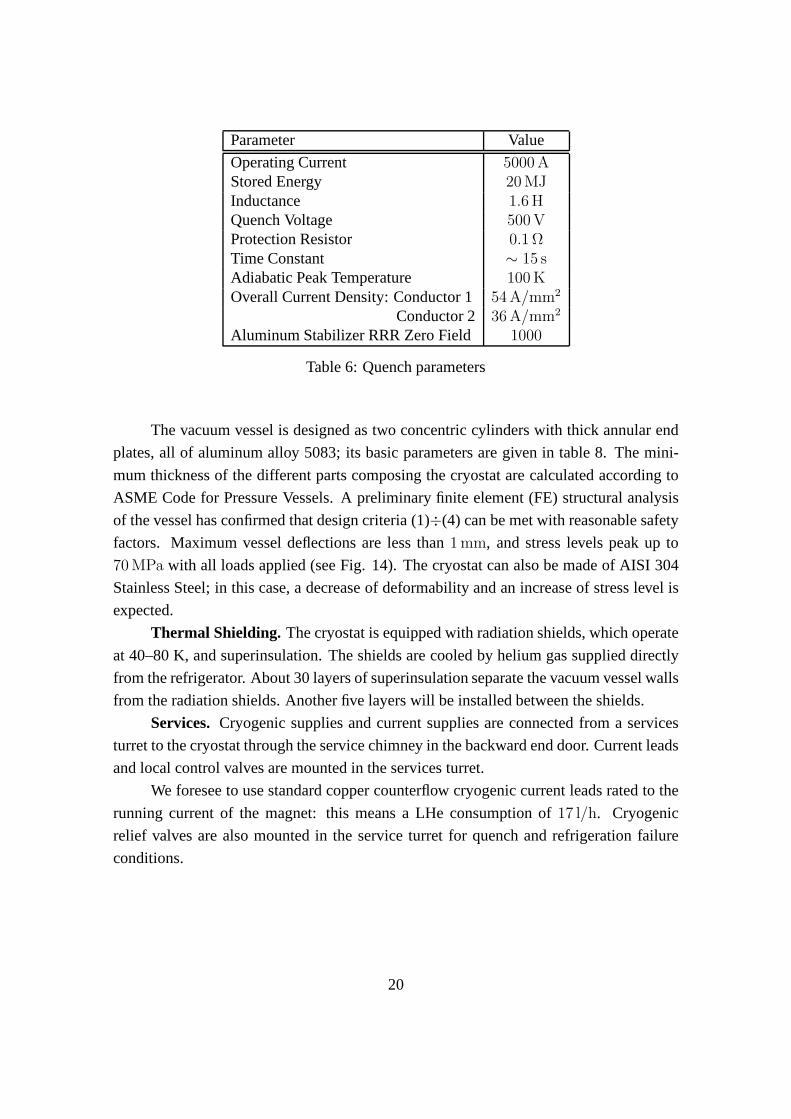
Parameter Value
Operating Current 5000 AStored Energy 20 MJInductance 1.6 HQuench Voltage 500 VProtection Resistor 0.1 ΩTime Constant ∼ 15 sAdiabatic Peak Temperature 100 KOverall Current Density: Conductor 154 A/mm2
Conductor 2 36 A/mm2
Aluminum Stabilizer RRR Zero Field 1000
Table 6: Quench parameters
The vacuum vessel is designed as two concentric cylinders with thick annular end
plates, all of aluminum alloy 5083; its basic parameters aregiven in table 8. The mini-
mum thickness of the different parts composing the cryostatare calculated according to
ASME Code for Pressure Vessels. A preliminary finite element(FE) structural analysis
of the vessel has confirmed that design criteria (1)÷(4) can be met with reasonable safety
factors. Maximum vessel deflections are less than1 mm, and stress levels peak up to
70 MPa with all loads applied (see Fig. 14). The cryostat can also bemade of AISI 304
Stainless Steel; in this case, a decrease of deformability and an increase of stress level is
expected.
Thermal Shielding. The cryostat is equipped with radiation shields, which operate
at 40–80 K, and superinsulation. The shields are cooled by helium gas supplied directly
from the refrigerator. About 30 layers of superinsulation separate the vacuum vessel walls
from the radiation shields. Another five layers will be installed between the shields.
Services. Cryogenic supplies and current supplies are connected froma services
turret to the cryostat through the service chimney in the backward end door. Current leads
and local control valves are mounted in the services turret.
We foresee to use standard copper counterflow cryogenic current leads rated to the
running current of the magnet: this means a LHe consumption of 17 l/h. Cryogenic
relief valves are also mounted in the service turret for quench and refrigeration failure
conditions.
20
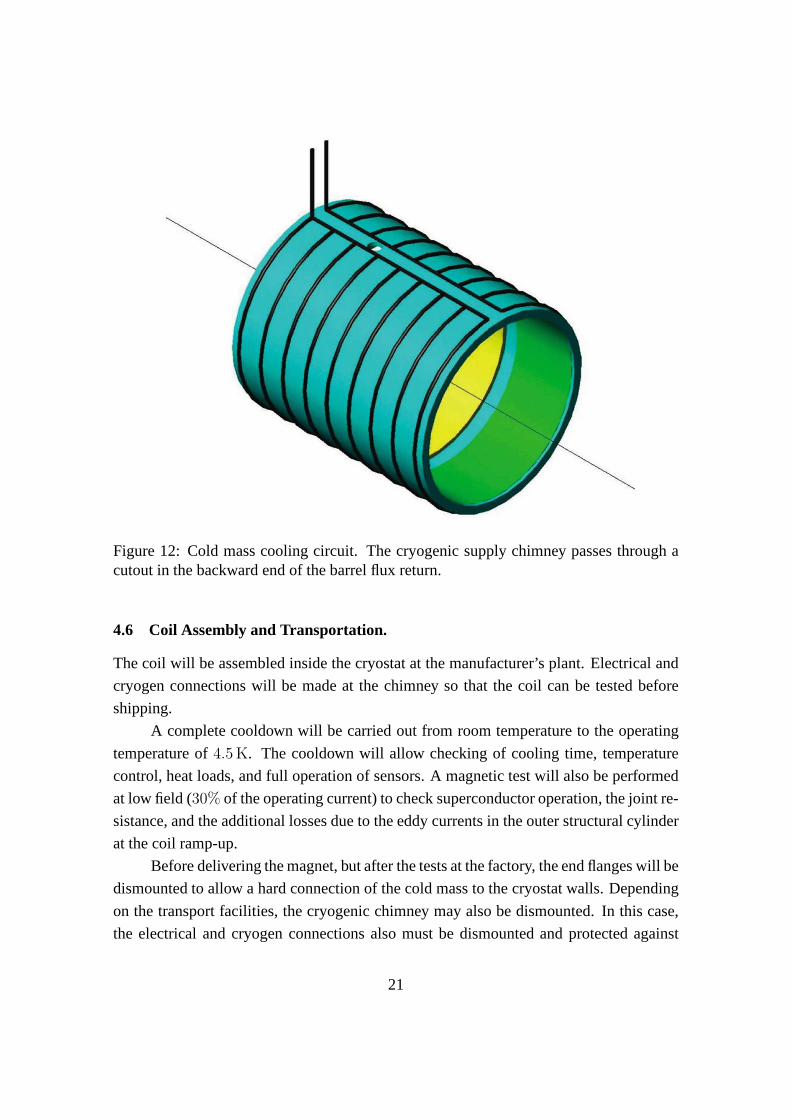
Figure 12: Cold mass cooling circuit. The cryogenic supply chimney passes through acutout in the backward end of the barrel flux return.
4.6 Coil Assembly and Transportation.
The coil will be assembled inside the cryostat at the manufacturer’s plant. Electrical and
cryogen connections will be made at the chimney so that the coil can be tested before
shipping.
A complete cooldown will be carried out from room temperature to the operating
temperature of4.5 K. The cooldown will allow checking of cooling time, temperature
control, heat loads, and full operation of sensors. A magnetic test will also be performed
at low field (30% of the operating current) to check superconductor operation, the joint re-
sistance, and the additional losses due to the eddy currentsin the outer structural cylinder
at the coil ramp-up.
Before delivering the magnet, but after the tests at the factory, the end flanges will be
dismounted to allow a hard connection of the cold mass to the cryostat walls. Depending
on the transport facilities, the cryogenic chimney may alsobe dismounted. In this case,
the electrical and cryogen connections also must be dismounted and protected against
21
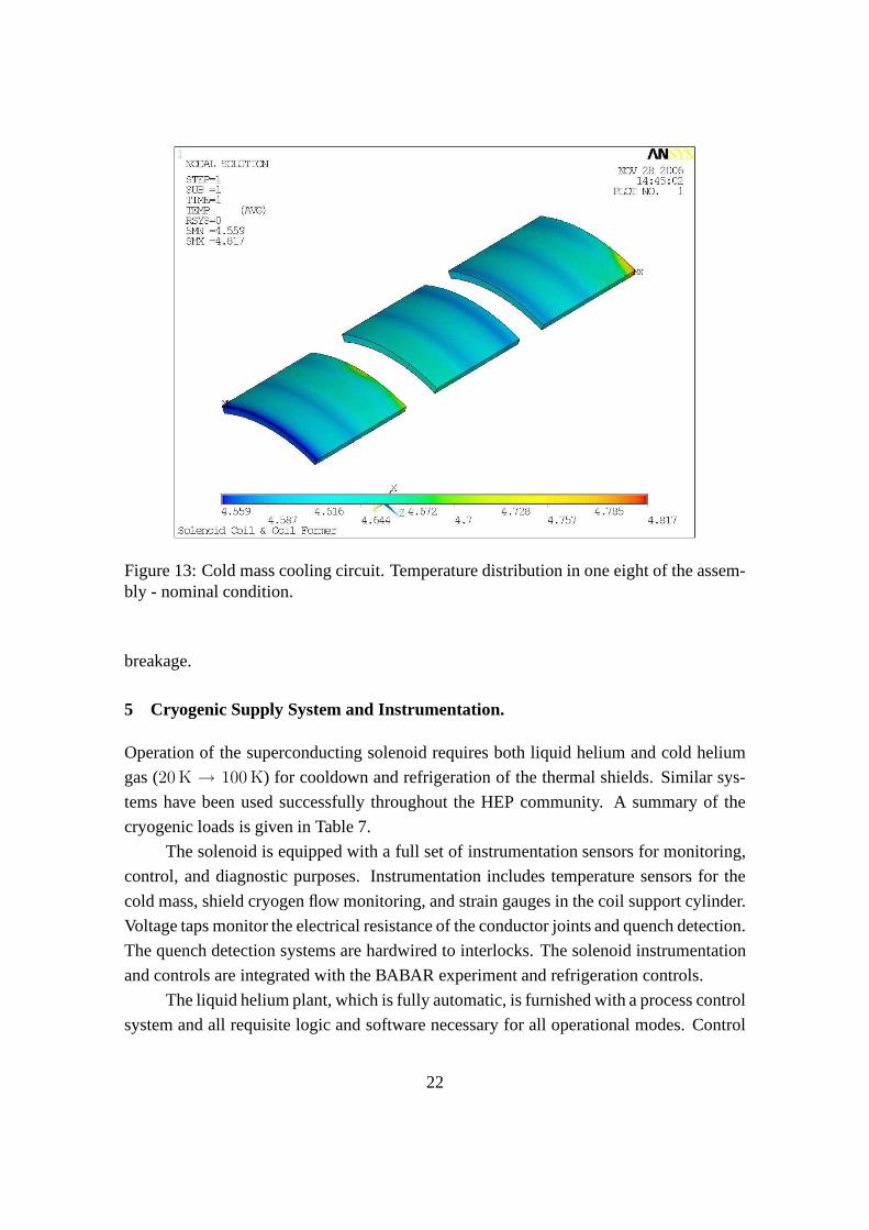
Figure 13: Cold mass cooling circuit. Temperature distribution in one eight of the assem-bly - nominal condition.
breakage.
5 Cryogenic Supply System and Instrumentation.
Operation of the superconducting solenoid requires both liquid helium and cold helium
gas (20 K → 100 K) for cooldown and refrigeration of the thermal shields. Similar sys-
tems have been used successfully throughout the HEP community. A summary of the
cryogenic loads is given in Table 7.
The solenoid is equipped with a full set of instrumentation sensors for monitoring,
control, and diagnostic purposes. Instrumentation includes temperature sensors for the
cold mass, shield cryogen flow monitoring, and strain gaugesin the coil support cylinder.
Voltage taps monitor the electrical resistance of the conductor joints and quench detection.
The quench detection systems are hardwired to interlocks. The solenoid instrumentation
and controls are integrated with the BABAR experiment and refrigeration controls.
The liquid helium plant, which is fully automatic, is furnished with a process control
system and all requisite logic and software necessary for all operational modes. Control
22
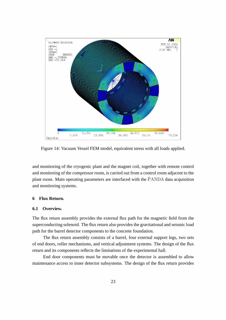
Figure 14: Vacuum Vessel FEM model, equivalent stress with all loads applied.
and monitoring of the cryogenic plant and the magnet coil, together with remote control
and monitoring of the compressor room, is carried out from a control room adjacent to the
plant room. Main operating parameters are interfaced with thePANDA data acquisition
and monitoring systems.
6 Flux Return.
6.1 Overview.
The flux return assembly provides the external flux path for the magnetic field from the
superconducting solenoid. The flux return also provides thegravitational and seismic load
path for the barrel detector components to the concrete foundation.
The flux return assembly consists of a barrel, four external support legs, two sets
of end doors, roller mechanisms, and vertical adjustment systems. The design of the flux
return and its components reflects the limitations of the experimental hall.
End door components must be movable once the detector is assembled to allow
maintenance access to inner detector subsystems. The design of the flux return provides
23
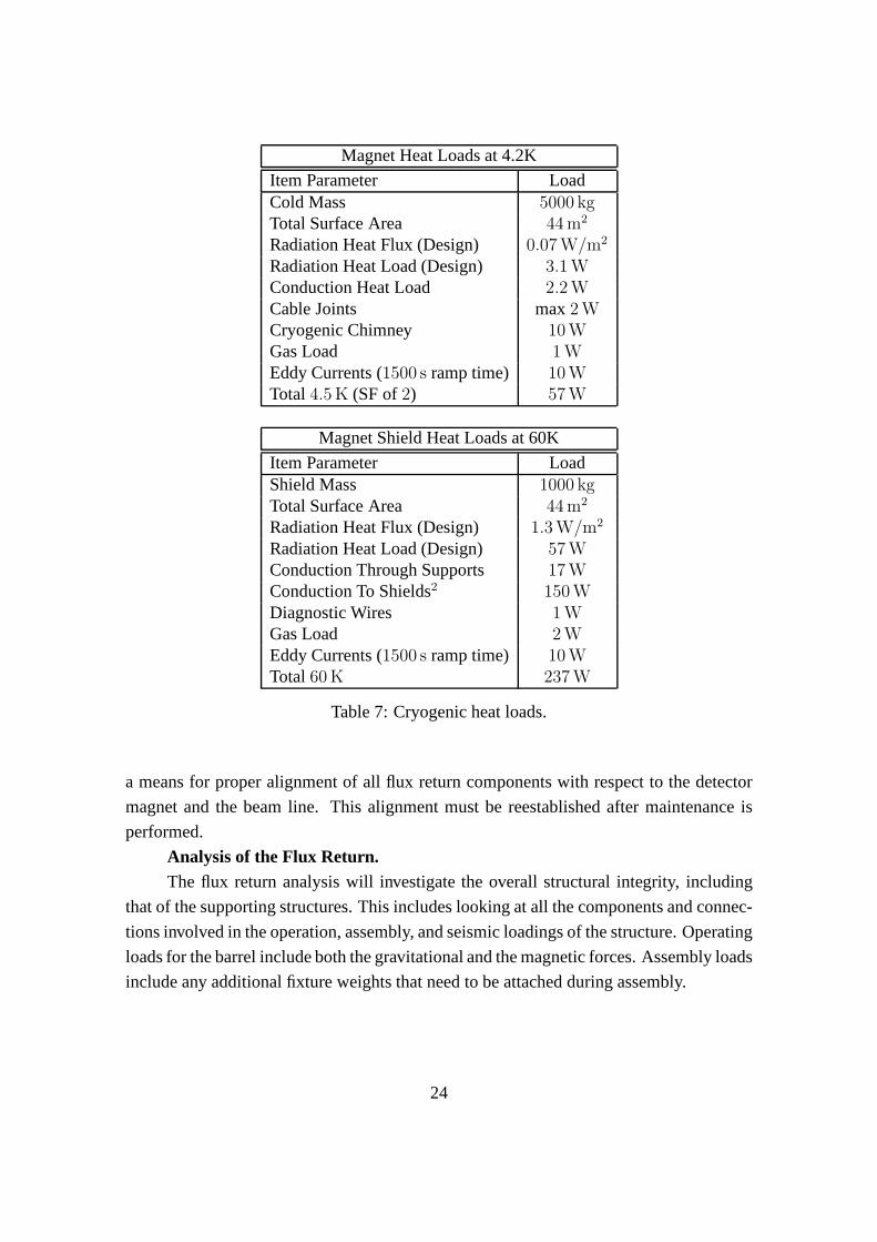
Magnet Heat Loads at 4.2K
Item Parameter LoadCold Mass 5000 kgTotal Surface Area 44 m2
Radiation Heat Flux (Design) 0.07 W/m2
Radiation Heat Load (Design) 3.1 WConduction Heat Load 2.2 WCable Joints max2 WCryogenic Chimney 10 WGas Load 1 WEddy Currents (1500 s ramp time) 10 WTotal4.5 K (SF of2) 57 W
Magnet Shield Heat Loads at 60K
Item Parameter LoadShield Mass 1000 kgTotal Surface Area 44 m2
Radiation Heat Flux (Design) 1.3 W/m2
Radiation Heat Load (Design) 57 WConduction Through Supports 17 WConduction To Shields2 150 WDiagnostic Wires 1 WGas Load 2 WEddy Currents (1500 s ramp time) 10 WTotal60 K 237 W
Table 7: Cryogenic heat loads.
a means for proper alignment of all flux return components with respect to the detector
magnet and the beam line. This alignment must be reestablished after maintenance is
performed.
Analysis of the Flux Return.The flux return analysis will investigate the overall structural integrity, including
that of the supporting structures. This includes looking atall the components and connec-
tions involved in the operation, assembly, and seismic loadings of the structure. Operating
loads for the barrel include both the gravitational and the magnetic forces. Assembly loads
include any additional fixture weights that need to be attached during assembly.
24
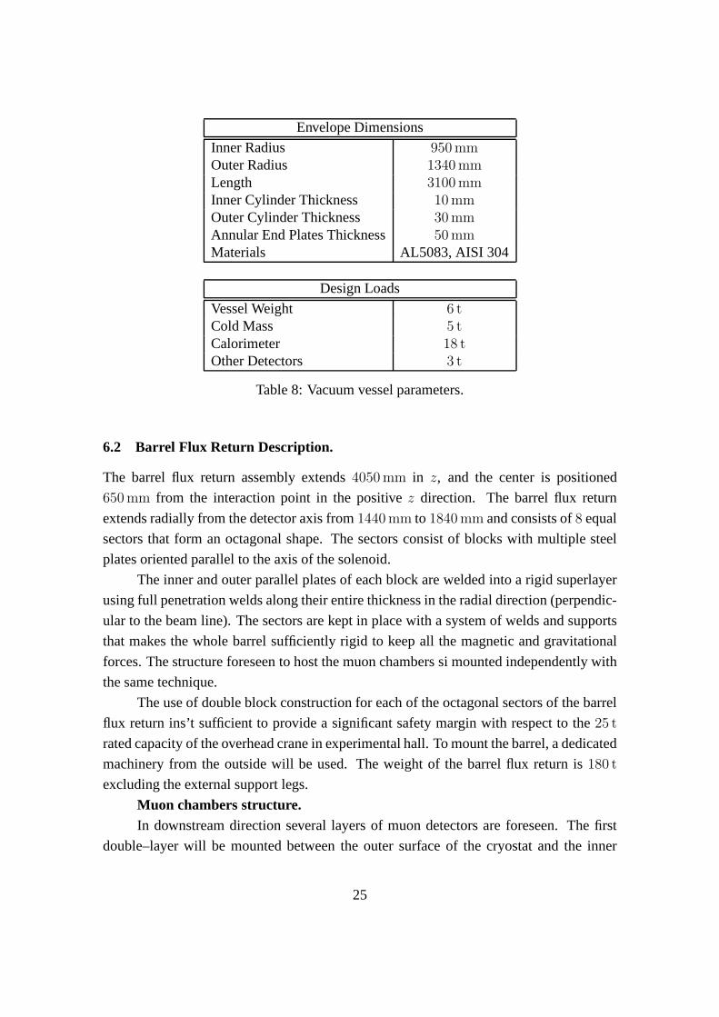
Envelope Dimensions
Inner Radius 950 mmOuter Radius 1340 mmLength 3100 mmInner Cylinder Thickness 10 mmOuter Cylinder Thickness 30 mmAnnular End Plates Thickness 50 mmMaterials AL5083, AISI 304
Design Loads
Vessel Weight 6 tCold Mass 5 tCalorimeter 18 tOther Detectors 3 t
Table 8: Vacuum vessel parameters.
6.2 Barrel Flux Return Description.
The barrel flux return assembly extends4050 mm in z, and the center is positioned
650 mm from the interaction point in the positivez direction. The barrel flux return
extends radially from the detector axis from1440 mm to 1840 mm and consists of8 equal
sectors that form an octagonal shape. The sectors consist ofblocks with multiple steel
plates oriented parallel to the axis of the solenoid.
The inner and outer parallel plates of each block are welded into a rigid superlayer
using full penetration welds along their entire thickness in the radial direction (perpendic-
ular to the beam line). The sectors are kept in place with a system of welds and supports
that makes the whole barrel sufficiently rigid to keep all themagnetic and gravitational
forces. The structure foreseen to host the muon chambers si mounted independently with
the same technique.
The use of double block construction for each of the octagonal sectors of the barrel
flux return ins’t sufficient to provide a significant safety margin with respect to the25 t
rated capacity of the overhead crane in experimental hall. To mount the barrel, a dedicated
machinery from the outside will be used. The weight of the barrel flux return is180 t
excluding the external support legs.
Muon chambers structure.In downstream direction several layers of muon detectors are foreseen. The first
double–layer will be mounted between the outer surface of the cryostat and the inner
25
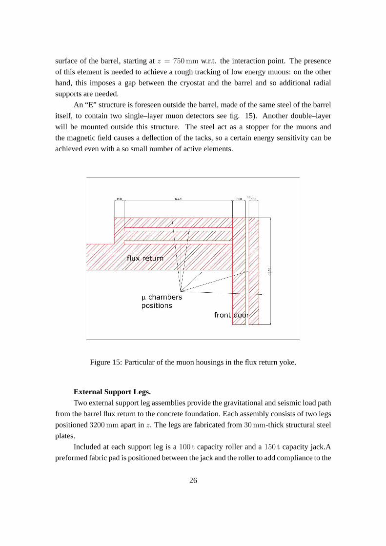
surface of the barrel, starting atz = 750 mm w.r.t. the interaction point. The presence
of this element is needed to achieve a rough tracking of low energy muons: on the other
hand, this imposes a gap between the cryostat and the barrel and so additional radial
supports are needed.
An “E” structure is foreseen outside the barrel, made of the same steel of the barrel
itself, to contain two single–layer muon detectors see fig. 15). Another double–layer
will be mounted outside this structure. The steel act as a stopper for the muons and
the magnetic field causes a deflection of the tacks, so a certain energy sensitivity can be
achieved even with a so small number of active elements.
Figure 15: Particular of the muon housings in the flux return yoke.
External Support Legs.Two external support leg assemblies provide the gravitational and seismic load path
from the barrel flux return to the concrete foundation. Each assembly consists of two legs
positioned3200 mm apart inz. The legs are fabricated from30 mm-thick structural steel
plates.
Included at each support leg is a100 t capacity roller and a150 t capacity jack.A
preformed fabric pad is positioned between the jack and the roller to add compliance to the
26
system. The horizontal spacing of the jack and roller assemblies is nominally5000 mm.
Each support leg is approximately2750 mm in length,1400 mm in width, and2000 mm
in height. The weight of each support leg assembly is approximately20 t.
6.3 End Door Description.
The forward and backward end doors are an array of steel plates that form a regular
octagon with a central round hole. Both in upstream and downstream direction the end
caps are vertically divided in two halves and can be open to let people operate inside the
barrel.
Each end door is mounted on a skid that permits it to be raised onto high load
capacity rollers by hydraulic jacks and to be moved on trackslocated in the experimental
hall. This provides a means to move the end doors into proper alignment with the barrel
prior to being bolted in place, and to be moved away from the barrel for maintenance
access to the detector. The center of gravity of the end door plates is high compared
to the depth of the base. The skid provides additional stability during the horizontal
accelerations experienced during moving or seismic events.
During operation, the magnet exerts an inward axial force that causes a significant
bending moment on the end door plates. The downstream end doors also support the
weight of the shielding screen of the dipole magnet and carrythe axial magnetic load
induced in the plug. To resist gravitational and seismic loads, and to limit the plate stresses
and deflections, all the end door plates are joined together to form a single structural
member.
The design of the end doors permits each door to be assembled and disassembled
inside the experimental hall with the existing facility crane. Each end door is therefore
composed of two weldments that are fastened together at installation. The inner weldment
consists of four50 mm plates, with each plate welded to a channel–shaped frame that
extends along the top and bottom of the octagon shape and along the boundary between
the right and left doors. Additional stiffeners are required to stiffen the weldment and help
maintain the necessary gap for the muon chambers. The outer weldment consists of three
50 mm plates welded together with similar stiffening members. The detailed analysis of
the response of the plates to the magnetic force distribution is not yet available, nor has
a detailed seismic analysis been done for the end door plates. Several design options are
being studied that can provide the necessary strength and stiffness.
The inner and outer weldments are joined together at installation by bolting each
weldment to the top of the skid along the bottom of the octagon, and by bolting tie plates
around the remaining perimeter of the weldments, except where the shielding plugs are
27
located. The outside tie plates are bolted in place after themuon chambers are installed,
and provisions for cabling are provided in these outside plates. These tie plates are also
used to attach the end doors to the barrel of the flux return.
In upstream direction, the diameter of the hole is fixed by theradius of the DIRC
used for PID: its design radius is550 ÷ 600 mm, so the hole radius is700 mm, in order
to house the trimming coil used to reduce the stray magnetic field in the DIRC PMT
region. The end cap has an octagonal shape and fits the dimensions of the return flux
barrel: the distance between two sides is3680 mm. The gap between the two weldments
is left vacant (except for stiffeners): the outer weldment roles as a clamp for the fringe
field which cannot be brought by the inner one.
In downstream direction the diameter of the hole is fixed by the geometrical accep-
tance of the detector: since the dipole part of the detector is intended to cover an angle
of 10 around the beam axis, an opening of600 mm is needed to let particles exiting at
small angles get out of the flux return. The distance between two far sides of the octagon
is 4480 mm. The gap between the two weldments hosts a single–layer of muon chambers
and a double–layer is foreseen just out of the outer weldment.
End Door Skids.Each end door is mounted on a skid that is equipped with four70 t capacity rollers,
and four45 t hydraulic jacks, one in each corner, which allow each of the doors to be
moved relative to the barrel for maintenance access. The rollers ride on hardened steel
tracks that are permanently located in the floor ofPANDA hall.
The end doors are bolted either to the barrel of the flux returnwhen in the oper-
ating position or to seismic restraint brackets when in the parked position. While the
doors are being moved, the30 t counter weight provides lateral stability for a horizontal
acceleration of0.3 g.
6.4 Options and Detailed Design Issues.
A detailed stress and deflection analysis is proceeding for the finalized overall envelope
dimensions. A detailed magnetic field and force analysis of the end doors ensures that
they will have adequate strength and stiffness to meet all the requirements imposed on
them. The tolerance on plate flatness must be defined togetherwith the envelope dimen-
sions of the Muon Chambers. Standard mill tolerances for plate flatness do not meet our
requirements for the end door plates to permit reliable MC installation; these tolerances
exceed15 mm, half the nominal gap width. This issue, together with weld distortion in
the plates during fabrication, must be resolved with both the plate supplier and the bar-
rel and end door fabricator. Other manufacturing tolerances must be established as the
28
system interface dimensions are finalized.
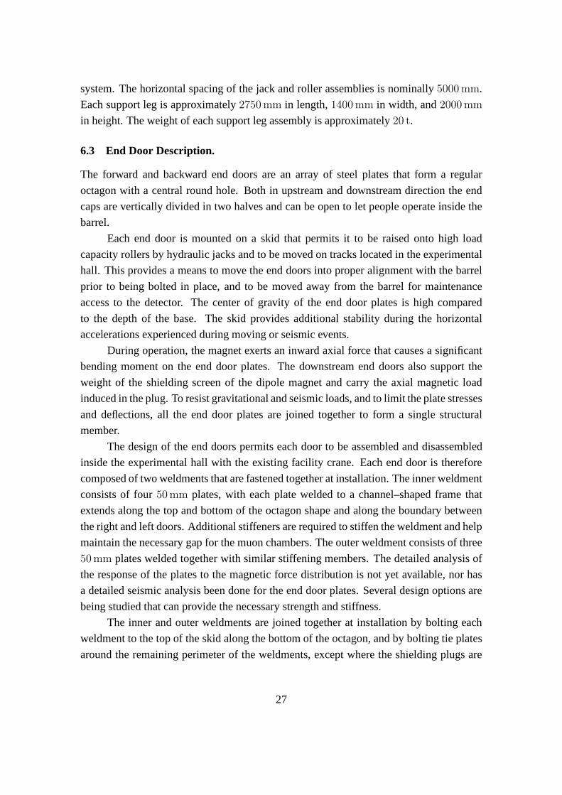
Figure 16: Step 1 - Outer base plates placement on back support structure
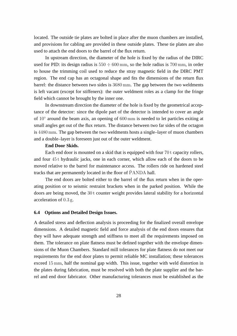
Figure 17: Step 2 - Inner lateral plates placement on supportstructure
29
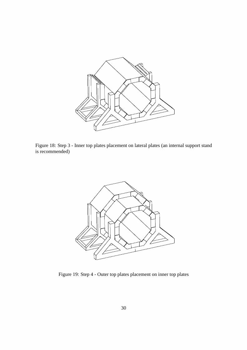
Figure 18: Step 3 - Inner top plates placement on lateral plates (an internal support standis recommended)
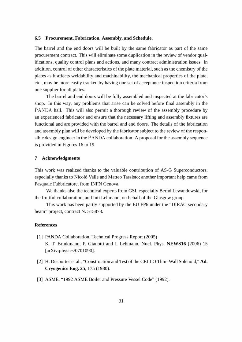
Figure 19: Step 4 - Outer top plates placement on inner top plates
30
6.5 Procurement, Fabrication, Assembly, and Schedule.
The barrel and the end doors will be built by the same fabricator as part of the same
procurement contract. This will eliminate some duplication in the review of vendor qual-
ifications, quality control plans and actions, and many contract administration issues. In
addition, control of other characteristics of the plate material, such as the chemistry of the
plates as it affects weldability and machinability, the mechanical properties of the plate,
etc., may be more easily tracked by having one set of acceptance inspection criteria from
one supplier for all plates.
The barrel and end doors will be fully assembled and inspected at the fabricator’s
shop. In this way, any problems that arise can be solved before final assembly in the
PANDA hall. This will also permit a thorough review of the assemblyprocedure by
an experienced fabricator and ensure that the necessary lifting and assembly fixtures are
functional and are provided with the barrel and end doors. The details of the fabrication
and assembly plan will be developed by the fabricator subject to the review of the respon-
sible design engineer in thePANDA collaboration. A proposal for the assembly sequence
is provided in Figures 16 to 19.
7 Acknowledgments
This work was realized thanks to the valuable contribution of AS-G Superconductors,
especially thanks to Nicolo Valle and Matteo Tassisto; another important help came from
Pasquale Fabbricatore, from INFN Genova.
We thanks also the technical experts from GSI, especially Bernd Lewandowski, for
the fruitful collaboration, and Inti Lehmann, on behalf of the Glasgow group.
This work has been partly supported by the EU FP6 under the “DIRAC secondary
beam” project, contract N. 515873.
References
[1] PANDA Collaboration, Technical Progress Report (2005)
K. T. Brinkmann, P. Gianotti and I. Lehmann, Nucl. Phys.NEWS16 (2006) 15
[arXiv:physics/0701090].
[2] H. Desportes et al., “Construction and Test of the CELLO Thin–Wall Solenoid,”Ad.Cryogenics Eng. 25, 175 (1980).
[3] ASME, “1992 ASME Boiler and Pressure Vessel Code” (1992).
31
[4] EuroCode3, “Design of steel structures”,EN-1993.
[5] CNR, “Costruzioni di acciaio. Istruzioni per il calcolo, l’esecuzione, il collaudo e la
manutenzione”,CNR 10011/97(1997).
[6] ANSYS INC, “General Finite Element Code,” Rev. 10.0 (2005).
[7] M.S. Lubell, “Empirical scaling formulas for critical current and critical field for
commercial NbTi”,IEEE Trans on Mag MAG-19 , 720 (1983).
[8] D. Andrews et al., “A Superconducting Solenoid for Colliding Beam Experiments,”
Ad. Cryogenic Eng. 27(1982).
[9] E. Baynham and P. Fabbricatore, “Superconducting Solenoid for the BABAR De-
tector,”BABAR TDR .
[10] A. Bonito Oliva et al., “ZEUS Magnets Construction Status Report,” 11th Int. Con-
ference on Magnet Technology,MT–11, 229 (1989).
[11] P. Clee et al., “Towards the Realization of Two 1.2 T Superconducting Solenoids for
Particle Physics Experiments,” 11th Int. Conference on Magnet TechnologyMT–11,
206 (1989).
[12] H. Desportes et al., “General Design and Conductor Study for the ALEPH Super-
conducting Solenoid,”J. Phys. (Paris) C1–341, (1984).
[13] Y. Doi et al., “A 3T Superconducting Magnet for the AMY Detector,” Nucl. Instr.Methods A274, 95 (1989).
[14] M.A. Green et al., “A Large Superconducting Thin Solenoid for the STAR Experi-
ment at RHIC,”IEEE Trans. App. Superconductivity, 104 (1993).
[15] C.M. Monroe et al., “The CLEO–II Magnet–Design, Manufacture, and Tests,”
ICEC–12, 773 (1988).
[16] M. Wake et al., “Excitation of a Superconducting Large Thin Solenoid Magnet,”
MAG–23, 1236 (1987).
[17] F. Wittgenstein et al., “Construction of the L3 Magnet,” 11th International Confer-
ence on Magnet Technology,MT–11, 131, (1989).
[18] A. Yamamoto et al., “Thin Superconducting Solenoid Wound with the Internal
Winding Method for Colliding Beam Experiments,”J. Phys. (Paris) C1–337,(1984).
32