isy node server developer’s manual ‘nls’ attribute to add/change node add device name add...
TRANSCRIPT

ISY
Node Server
Developer’s Manual
REST Interface
Based on firmware 5.0.4

ISY Node Server Developer’s Manual : REST SDK
Universal Devices, Inc.
Page - 2 -
TABLE OF CONTENTS
REVISION HISTORY 5
1. INTRODUCTION 6
2. WHAT IS A NODE? 6
3. NODE SERVER CONFIGURATION ON ISY 6
3.1 Files 6
3.2 Network Connection 7
3.2.1 From Isy to Node Server 7
3.2.2 From Node Server to Isy 8
3.2.3 Responses 8
3.3 Serial Connection 8
4. REQUIRED API SUPPORT IN NODE SERVER 9
4.1 General 9
4.1.1 Request IDs 9 <base>/….[?requestId=<requestId>] 9
4.1.2 Node Addresses 9
4.2 Install 10 <base>/install/<profileNumber> 10
4.3 Query node 10 <base>/nodes/<nodeAddress>/query[?requestId=<requestId>] 10
4.4 Get Node Status Values 10 <base>/nodes/<nodeAddress>/status[?requestId=<requestId>] 10
4.5 Add All Nodes 11 <base>/add/nodes[?requestId=<requestId>] 11
4.6 Reports from ISY 11 <base>/nodes/<nodeAddress>/report/add/<nodeDefId>?primary=<nodeAddress>&name=<nodeName> 11 <base>/nodes/<nodeAddress>/report/remove 11 <base>/nodes/<nodeAddress>/report/rename?name=<nodeName> 11 <base>/nodes/<nodeAddress>/report/enable 11

ISY Node Server Developer’s Manual : REST SDK
Universal Devices, Inc.
Page - 3 -
<base>/nodes/<nodeAddress>/report/disable 11
4.7 Run a command 12
5. REST SUPPORT IN ISY 13 - URL Prefix: 13 - The profileNumber specified on the URL determines which ISY userid/password will be accepted by
the ISY for the request. 13
5.1 Reporting status updates 13
5.2 Reporting a command 14
5.3 Node Management 15
5.4 Reporting ISY Request status 16
6. National Language Support (NLS) 17
6.1 General 17
6.2 Naming Convention Terminology 18
6.3 Device name 19
6.4 Icons 19
6.5 Status Names 19
6.6 Command Names 19
6.7 Command Parameter Names 19
6.8 Other Names 20
6.9 Name mapped Values (Index, Percent) 20
6.10 Formatting in Programs 21
6.10.1 Commands 21
6.10.1.1 Command Formatting Examples 22
6.10.2 Status Conditions 22
6.10.3 Control Conditions 23
7. APPENDIX 24
7.1 Editors 24
7.2 Encoded Editor ID 25

ISY Node Server Developer’s Manual : REST SDK
Universal Devices, Inc.
Page - 4 -
7.3 Node Definitions 26
7.4 Icons 27
7.5 Driver Controls 28
7.6 Units of Measure 30

ISY Node Server Developer’s Manual : REST SDK
Universal Devices, Inc.
Page - 5 -
Revision History
Date Firmware Description 2016/04/03 5.0.4 Add ‘hide’ option to status values in nodedef
Add encoded editor IDs
Removed editor definitions from nodedef
2016/02/02 5.0.2 Add ‘${vo}’ option to command formatting
Add Raw x-byte units of measure
Add GEN, CMDPN for command and parameter nls
Add GV0 Driver Control
2015/08/28 5.0.1 Add Driver Control, and UOM tables
Fixed example for submit cmd
Add ‘nls’ attribute to Add/Change node
Add Device Name
Add Icons
Removed node type (may revisit in future release)
2015/05/12 4.5.1 Clarifications of APIs and NLS files
2015/04/12 4.5 Initial

ISY Node Server Developer’s Manual : REST SDK
Universal Devices, Inc.
Page - 6 -
1. Introduction
ISY is an award winning platform for automation and energy management. With the
introduction of Node Servers, the ISY now supports any protocol implemented by a third
party in much that same way that INSTEON, Z-Wave and Zigbee are supported.
The concepts remain the same. The big difference is that instead of the ISY generating the
events and running device commands, the node server does.
2. What is a Node?
A node represents all, or a subset of, a physical device such as lamp, switch and keypad,
smoke detector, etc., or a conceptual device such as weather information or even stock
quotes.
A node definition is used to describe a node. It contains the list of status values it
maintains (e.g. the current temperature, heat/cool setpoints for a thermostat), the list of
commands it accepts (e.g. on/off for a dimmer lamp), and a list of the commands it may
send out (e.g. on/off for a dimmer switch).
A node server simply defines the set of nodes its supports, and provides the REST services
to support them.
3. Node Server Configuration on ISY
3.1 Files
/editor Contains all the XML editors files (.xml)
/nodedef Contains all the XML node definitions (.xml)
/nls Contains all the NLS properties files (.txt)
/version.txt Contains the version of these files
These files are normally supplied as a .zip file by the node server developer
and installed by the user through the ISY Admin console. In each directory,
one or more files may be used. All filenames are restricted to 8.3 format.
If the node server developer creates a new version of the files, they can be
installed over the old ones on the ISY. It is up to the node server developer to
ensure any required backwards compatibility of nodes.
e.g. Example Zip File contents
/editor/edit.xml

ISY Node Server Developer’s Manual : REST SDK
Universal Devices, Inc.
Page - 7 -
/nodedef/ndef.xml
/nls/EN_US.txt
/version.txt
/editor
An editor defines the parameters for a widget in the client, such as a
combobox, a numeric field etc. It defines the set of values and the unit(s) of
measure available. An editor may contain multiple <range> entries, each of
which must have a unique UOM.
/nodedef
A node definition defines the status and commands available to a node.
/nls
A single NLS file is used for each language. The naming convention is
<language>_<countryCode>.txt (e.g. en_US.txt for USA English)
NLS is a set of name/value pairs used to display values in national language
(such as English).
3.2 Network Connection
3.2.1 From Isy to Node Server
The REST API is used to communicate with a node server when using a
network connection. The ISY uses basic authentication with either http or
https to communicate with the node server. A custom base URL is also
prepended to the REST command, allowing the node server to customize the
location of its REST support.
For example, if a base URL of /nodeservers/joe is configured, then the
following URL would be sent to the node server to query a node:
/nodeservers/joe/nodes/<nodeAddress>/query
Having a base URL also allows a device to support multiple node servers, each
with its own unique base URL.

ISY Node Server Developer’s Manual : REST SDK
Universal Devices, Inc.
Page - 8 -
3.2.2 From Node Server to Isy
The node server must use basic authentication with either http or https to
communicate with the ISY. It must also know the profile number the node
server has been assigned on the ISY because most REST API calls require this
number in the URL. The ISY uses the profile number to ensure only the nodes
owned by the profile can be modified, and to choose the ISY user number the
node server should be using.
For example, if the node server has been assigned profile number 5, then
something like the following URL would be used to update device status in
ISY:
/rest/ns/5/nodes/n005_dimmer_2/report/status/ST/25.2/percent
3.2.3 Responses
When a Node Server receives a REST command, one of the following
responses must be sent out immediately, before processing the request. The
ISY will send a similar response after processing a request.
200 - HTTP_OK
Valid request received, will run it
404 - HTTP_NOT_FOUND
Unrecognized request received and ignored.
503 - HTTP_SERVICE_UNAVAILABLE
Valid request received but ignored because system too busy to run it
If the userid/password is missing or incorrect
401 - HTTP_UNAUTHORIZED
User authentication failed
3.3 Serial Connection
Support may be added at a later time for node servers using serial connections.

ISY Node Server Developer’s Manual : REST SDK
Universal Devices, Inc.
Page - 9 -
4. Required API support in Node Server
4.1 General
Each node server is required to support a set of APIs that the ISY will use to
manage the nodes being supplied by the node server. Primarily, these APIs are
used to add/delete/rename nodes, send commands to nodes, and request node
information. Other APIs request the node server to install or upgrade itself on
the ISY, and generally manage the configuration of the node server.
4.1.1 Request IDs
<base>/….[?requestId=<requestId>]
On most API calls, the ISY can optionally supply a requestId. If a requestId
appears on the URL then the node server must send a success or fail message
back to the ISY after it has completed the requested action, and, after all
messages from that completed action have been sent to the ISY.
This allows the ISY to run a command synchronously. For example, the ISY
may need to query a device and use the results of the query to do some
additional processing.
4.1.2 Node Addresses
All node addresses are given a prefix assigned by the ISY. The prefix is
unique to the node server thus guaranteeing that all node addresses on the ISY
are unique.
The format of the node address prefix is:
naaa_
Where aaa is the profile number assigned to the node server in the ISY. A
node address is made up of any combination of lowercase letters, numbers, and
‘_’ character.
A node address for profile 5 could look something like:
n005_dimmer_3_1
The dimmer_3_1 portion of the node address is completely defined by the
node server or the user creating the node.
The maximum node length (including the prefix) is 19 characters.

ISY Node Server Developer’s Manual : REST SDK
Universal Devices, Inc.
Page - 10 -
4.2 Install
<base>/install/<profileNumber>
Instructs the node server to install all the profile files for the node server (rather
than having the user do it through the ISY admin console). This is done by
removing the old files and then adding all the files one by one, as follows:
- /rest/ns/<profileNumber>/profile/remove
- For each file:
o /rest/ns/<profileNumber>/profile/upload/<dir>/<filename>
- /rest/ns/<profileNumber>/profile/reload
NOTE: In the current implementation, the ISY must be restarted for the new
files to take effect.
4.3 Query node
<base>/nodes/<nodeAddress>/query[?requestId=<requestId>]
The node server must query the specified node, and send the results to the ISY
using the Report Status Rest command.
If a requestId is specified, the status of the request must be sent to the ISY after
all other messages are sent.
If a <nodeAddress> of “0” is specified, then all nodes must be queried.
4.4 Get Node Status Values
<base>/nodes/<nodeAddress>/status[?requestId=<requestId>]
The node server sends the current status values for the specified node to the
ISY using the Report Status Rest command.
If a requestId is specified, the status of the request must be sent to the ISY after
all other messages are sent.
If a <nodeAddress> of “0” is specified, then statis for all nodes must be sent.

ISY Node Server Developer’s Manual : REST SDK
Universal Devices, Inc.
Page - 11 -
4.5 Add All Nodes
<base>/add/nodes[?requestId=<requestId>]
Instructs the node server to add all of its nodes to the ISY (see Node
Management).
If a requestId is specified, the status of the request must be sent to the ISY after
all other messages are sent.
4.6 Reports from ISY
Reports provided by the ISY give the node server an opportunity to update its
own database of nodes.
<base>/nodes/<nodeAddress>/report/add/<nodeDefId>?primary=<nodeAddress>&name=<nodeName>
- Reports to the node server that the given node was added to the ISY.
<base>/nodes/<nodeAddress>/report/remove - Reports to the node server that the given node was removed from the
ISY.
<base>/nodes/<nodeAddress>/report/rename?name=<nodeName> - Reports to the node server that the given node was renamed in the ISY.
<base>/nodes/<nodeAddress>/report/enable - Reports to the node server that the given node was enabled in the ISY.
<base>/nodes/<nodeAddress>/report/disable - Reports to the node server that the given node was disabled in the ISY.
NOTE: In the future, there may be additional APIs added that allow the node
server more control over the actual creation and modification of nodes.

ISY Node Server Developer’s Manual : REST SDK
Universal Devices, Inc.
Page - 12 -
4.7 Run a command
<base>/nodes/<nodeAddress>/cmd/<command> <base>/nodes/<nodeAddress>/cmd/<command>/<value> <base>/nodes/<nodeAddress>/cmd/<command>/<value>/<uom> [?<p1>.<uom1>=<val1>&<p2>...][requestId=<requestId>] The node server must run the specified command for the specified node. This
command may have originated from an ISY program, the standard ISY REST
API, the admin console, or any other client. The commands normally sent are
those listed in the <accepts> section of the node definition used for the given
node.
The numeric value of the UOM is always supplied and is never one of the
common names. For example, 51 will be used instead of ‘percent’. For
parameters in the <pX>.<uomX> format, the numeric uom value is always
prefixed by ‘uom’
If a requestId is specified, the status of the running the command must be sent
to the ISY after the command has completed or failed.
nodeAddress The full address of the node (e.g. ‘n005_switch_1)
command The command to perform (e.g. ‘DON’, ‘CLISPH’, etc.)
pN Nth Parameter name (e.g. ‘level’)
uomN Unit of measure of the Nth parameter (e.g. ‘uom58’)
valN The numeric value of the Nth parameter (e.g. ‘80’, ’80.01’ etc,)
Commands may also have an unnamed parameter
value The value of the unnamed parameter.
uom Unit of measure of the value of the unnamed parameter (e.g. 51)
E.g.
/myserver/nodes/n005_switch_1/cmd/DON
/myserver/nodes/n005_switch_1/cmd/DON/80/51
/myserver/nodes/n005_switch_1/cmd/DON?level.uom51=80
/myserver/nodes/n005_switch_1/cmd/DON/80/percent?rate.uom58=0.3

ISY Node Server Developer’s Manual : REST SDK
Universal Devices, Inc.
Page - 13 -
5. REST support in ISY
REST is an easy to use URL based command set which allows the developer to
communicate with the ISY.
Unless otherwise specified, all REST commands use HTTP GET method.
If no Response is provided, then UDIDefaultResponse must be assumed:
WSDL:zw:UDIDefaultResponse
Notes:
- URL Prefix: /rest/ns/<profileNumber>/ - The profileNumber specified on the URL determines which ISY
userid/password will be accepted by the ISY for the request.
5.1 Reporting status updates
/nodes/<nodeAddress>/report/status/<driverControl>/<value>/<uom>
Updates the ISY with the current value of a driver control (e.g. the current
temperature, light level, etc.)
nodeAddress The full address of the node (e.g. ‘n005_dimmer_1’)
driverControl The name of the status value (e.g. ‘ST’, ‘CLIHUM’, etc.)
value The numeric status value (e.g. ’80.5’)
uom Unit of measure of the status value
E.g. /rest/ns/5/nodes/n005_dimmer_2/report/status/ST/25.2/percent

ISY Node Server Developer’s Manual : REST SDK
Universal Devices, Inc.
Page - 14 -
5.2 Reporting a command
/nodes/<nodeAddress>/report/cmd/<command> /nodes/<nodeAddress>/report/cmd/<command>/<value> /nodes/<nodeAddress>/report/cmd/<command>/<value>/<uom> [?<p1>.<uom1>=<val1>&<p2>.<uom2>=<val2>&<p3>…]
Sends a command to the ISY that may be used in programs and/or scenes. A
common use of this is a physical switch that somebody turns on or off. Each
time the switch is used, a command should be reported to the ISY. These are
used for scenes and control conditions in ISY programs.
nodeAddress The full address of the node (e.g. ‘n005_switch_1)
command The command to perform (e.g. ‘DON’, ‘CLISPH’, etc.)
pN Nth Parameter name (e.g. ‘level’)
uomN Unit of measure of the Nth parameter (e.g. ‘seconds’, ‘uom58’)
valN The numeric value of the Nth parameter (e.g. ‘80’, ’80.01’ etc,)
Commands may also have an unnamed parameter
value The value of the unnamed parameter.
uom Unit of measure of the value of the unnamed parameter
E.g.
/rest/ns/5/nodes/n005_switch_1/report/cmd/DON
/rest/ns/5/nodes/n005_switch_1/report/cmd/DON/80/percent
/rest/ns/5/nodes/n005_switch_1/report/cmd/DON?level.percent=80
/rest/ns/5/nodes/n005_switch_1/report/cmd/DON/80/percent?rate.uom58=0.3

ISY Node Server Developer’s Manual : REST SDK
Universal Devices, Inc.
Page - 15 -
5.3 Node Management
/nodes/<nodeAddress>/add/<nodeDefId>?primary=<primary>&name=<nodeName>[&nls=<nlsKey>]
Adds a node to the ISY. To make this node the primary, set primary to the
same value as nodeAddress
nodeAddress The full address of the node (e.g. ‘n005_dimmer_1’)
nodeDefId The id of the node definition to use for this node
primary The primary node for the device this node belongs to
nodeName The name of the node
nls (Optional) NLS key string for information specific to this node
E.g.
/rest/ns/5/nodes/n005_dimmer_2/add/MyDimmer?primary=n005_dimmer_1&
name=Dimmer 2&nls=012B
/add/nodes
Sends a request to the node server to have it add all of its nodes to the ISY.
This API is intended for ISY clients, and is never used by a node server.
E.g. /rest/ns/5/add/nodes
/nodes/<nodeAddress>/change/<nodeDefId>[?nls=<nlsKey>]
Changes the node definition to use for an existing node. An example of this is
may be to change a thermostat node from Fahrenheit to Celsius.
nodeAddress The full address of the node (e.g. ‘n005_dimmer_1’)
nodeDefId The id of the node definition to use for this node
nls (Optional) NLS key string for information specific to this node
E.g. /rest/ns/5/nodes/n005_tstat_1/change/ThermostatCelsius?nls=4511

ISY Node Server Developer’s Manual : REST SDK
Universal Devices, Inc.
Page - 16 -
/nodes/<nodeAddress>/remove
Removes a node from the ISY. A node cannot be removed if it is the primary
node for at least one other node.
nodeAddress The full address of the node (e.g. ‘n005_dimmer_1’)
E.g. /rest/ns/5/nodes/n005_dimmer_2/remove
5.4 Reporting ISY Request status
/report/status/<requestId>/fail /report/status/<requestId>/success When the ISY sends a request to the node server, the request may contain a
‘requestId’ field. This indicates to the node server that when the request is
completed, it must send a fail or success report for that request. This allows
the ISY to in effect, have the node server synchronously perform tasks. This
message must be sent after all other messages related to the task have been
sent.
For example, if the ISY sends a request to query a node, all the results of the
query must be sent to the ISY before a fail/success report is sent.
requestId The request ID the ISY supplied on a request to the node server.
E.g. /rest/ns/5/report/request/1234/success

ISY Node Server Developer’s Manual : REST SDK
Universal Devices, Inc.
Page - 17 -
6. National Language Support (NLS)
6.1 General NLS support is defined for a node server by the set of properties files in the
/nls subdirectory. They contain the name/value pairs used by the clients and
the ISY to display commands, values, controls etc.. All NLS names must be in
uppercase.
A naming convention is used to organize these values.

ISY Node Server Developer’s Manual : REST SDK
Universal Devices, Inc.
Page - 18 -
6.2 Naming Convention Terminology
The following table shows the various attributes from XML node definitions
and editors that are used in this chapter to describe how to build the name of a
particular NLS value.
<node.nls> The ‘nls’ attribute specified when adding or changing a node.
e.g.
/rest/ns/5/nodes/n005_dimmer_2/add/MyDimmer?primary=n
005_dimmer_1&name=Dimmer 2&nls=012B
<nodedef.id> The ‘id’ attribute of a node definition.
e.g. <nodeDef id="Thermostat" nls="tstat">
<nodedef.nls> The ‘nls’ attribute of a node definition.
e.g. <nodeDef id="Thermostat" nls="tstat">
<editor.id> The ‘id’ attribute of an editor
e.g <editor id="I_OL">
<range.nls> The ‘nls’ attribute of a range
e.g. <range uom="25" subset="0-32" nls="IX_I_RR" />
<st.id> The ‘id’ attribute of a status
e.g. <st id="CLIHUM" editor="I_TSTAT_HUM" />
<cmd.id> The ‘id’ attribute of a command
e.g. <cmd id="DON">
<p.id> The ‘id’ attribute of a command parameter
e.g. <p id="COLOR" editor="I_COLOR_RGB" />

ISY Node Server Developer’s Manual : REST SDK
Universal Devices, Inc.
Page - 19 -
6.3 Device name
The same node definition may be used for different products/models of a
device. For example, there may be many different models of a dimmer lamp,
but they are functionally equivalent and therefore use the same node definition.
The device name is used to specify the actual product name/model etc. of the
device for a specific node.
DEV-<node.nls>-NAME
e.g. DEV-0102-NAME = (2475D) In-LineLinc Dimmer
6.4 Icons
The format and lookup order of the NLS entry for icons is:
DEV-<node.nls>-ICON
NDN-<nodedef.nls>-ICON ND-<nodedef.id>-ICON
e.g. DEV-0341-ICON = Thermostat
NDN-TStat-ICON = Thermostat
ND-MyThermostat-ICON = Thermostat
See Icons for the list of supported icons
6.5 Status Names
Some status values require different names for different node definitions. For
example, ST for a dimmer should show up as ‘Lamp’, but ST for a drapery
motor should show up as ‘Drapes’. The format and lookup order of the NLS
entry is:
ST-<nodedef.nls>-<st.id>-NAME
GEN-<nodedef.nls>-<st.id>-NAME
ST-<st.id>-NAME e.g. ST-ST-NAME = Lamp
ST-MYDRAPES-ST-NAME = Drapes
6.6 Command Names
The format and lookup order of the NLS entry for command names is:
CMD-<nodedef.nls>-<cmd.id>-NAME
CMD-<cmd.id>-NAME e.g. CMD-DON-NAME = On
CMD-MYDRAPES-DON-NAME = Open
6.7 Command Parameter Names

ISY Node Server Developer’s Manual : REST SDK
Universal Devices, Inc.
Page - 20 -
The format and lookup order of the NLS entry for command parameter names
is:
GEN-<p.nls>-NAME
CMDP-<nodedef.nls>-<editor.id>-<p.id>-NAME
CMDPN-<nodedef.nls>-<p.id>-NAME
GEN-<nodedef.nls>-<p.id>-NAME
CMDP-<editor.id>-<p.id>-NAME
CMDP-<p.id>-NAME
e.g. GEN-MYTIMER001-NAME = On/Off Timer
6.8 Other Names
node definition ND-<nodedef.id>-NAME
6.9 Name mapped Values (Index, Percent)
Some integer values may be displayed as names instead of numeric values.
Index values (uom 25), and some percent values are commonly made into
names. For example, displaying the values 0-31 for Insteon Ramp Rates is not
very meaningful compared to names indicating the actual durations. ‘On’ and
‘Off’ are often displayed for percentage values, while the remaining values 1-
99 are usually displayed numerically.
The format of the NLS entry for mapped values is:
<range.nls>-<value>
e.g. Insteon Ramp Rates
<range id="I_RR" uom="25" subset="0-31" nls="IX_I_RR" />
IX_I_RR-0 = 9.0 minutes
IX_I_RR-1 = 8.0 minutes
...
IX_I_RR-31 = 0.1 seconds

ISY Node Server Developer’s Manual : REST SDK
Universal Devices, Inc.
Page - 21 -
6.10 Formatting in Programs
Each line of a program is formatted and displayed in different way. Custom
formatting entries are used for node conditions and commands, as follows:
6.10.1 Commands
The format and lookup order of the NLS entry for program command entries
is:
PGM-CMD-<nodedef.nls>-<cmd.id>-FMT
PGM-CMD-<cmd.id>-FMT e.g. (All on one line)
PGM-CMD-DON-FMT = /level/${c}/to ${v}/ /ramprate// in ${v}/
/offtimer//, turn off ${v} later/
/<param.id>/param text if omitted/param text if not omitted/ [.. next
parameter, …]
e.g. /level/${c}/to ${v}/ /ramprate// in ${v}/
/ First character defines what character to use as separator,
normally '/' is used
param.id Id of the parameter (e.g. 'level')
Note: This is empty for an unnamed parameter
param text if omitted
String to show if the parameter was omitted
param text if not omitted
String to show if the parameter was specified
The string for parameter text supports the following variables:
${c} Name of the command
${v} Formatted value of the parameter (including UOM)
${vo} Formatted value of the parameter (without UOM)
${uom} Formatted UOM without the value
${op} Operator used (conditions only)

ISY Node Server Developer’s Manual : REST SDK
Universal Devices, Inc.
Page - 22 -
6.10.1.1 Command Formatting Examples Assume commands are for node 'MyDevice'
1) A command with three named parameters, 'num', 'val', 'len'
/num//${c} Parameter ${v}/ /val/ default/ = ${v}/ /len// (${v} bytes)/
The following program action line would be shown for:
${c} = "Config", num=1, val=20, and len=4:
[Config Parameter 1][ = 20][ (4 bytes)]
--> "Set 'MyDevice' Config Parameter 1 = 20 (4 bytes)"
${c} = "Config", num=5, val=25, and len omitted:
[Config Parameter 5][ = 25][]
--> "Set 'MyDevice' Config Parameter 5 = 25"
${c} = "Device", num=5, val omitted, and len=2:
[Device Parameter 5][ default][ (2 bytes)]
--> "Set 'MyDevice' Device Parameter 5 default (2 bytes)"
2) A command with one unnamed parameter
//default/${v}/
value of unnamed param omitted
[default] --> "Set 'MyDevice' default"
value of unnamed param = 50 percent
[50%] --> "Set 'MyDevice' 50%"
3) A command with no parameters shows just the command name and does
not require and PGM-xxxxx entry
DFON --> "Set 'MyDevice' Fast On"
Another example:
PGM-CMD-DON-FMT = /level/${c}/to ${v}/ /ramprate// in ${v}/
/offtimer//, turn off ${v} later/
level=50%, ramprate=3 seconds, offtimer=5 minutes
"[to 50%][ in 3 seconds][, turn off 5 minutes later]"
--> "Set 'MyDevice' to 50% in 3 seconds, turn off 5 minutes later"
6.10.2 Status Conditions
The format and lookup order of the NLS entry for status condition format
entries is:
PGM-ST-<nodedef.nls>-<st.id>-FMT
PGM-ST-<st.id>-FMT
The value is a single param text string similar to that specified for a command
parameter.
e.g. PGM-ST-CLISPH-FMT = ${c} ${op} ${v}
If not specified, then the following is used: ${c} ${op} ${v}

ISY Node Server Developer’s Manual : REST SDK
Universal Devices, Inc.
Page - 23 -
6.10.3 Control Conditions
There are no custom entries for control conditions, because currently, control
conditions do not include any of the command parameters.

ISY Node Server Developer’s Manual : REST SDK
Universal Devices, Inc.
Page - 24 -
7. Appendix
7.1 Editors <editors>
<editor id="I_OL">
<range uom="51" subset="0-100" />
<range uom="56" subset="0-255" />
</editor>
<editor id=”TEMP_C”>
<range uom=”4” min=”4.5” max=”32” step=”0.5” prec=”1” />
</editor>
<editor id="I_RR">
<range uom="25" subset="0-32" nls="IX_I_RR_" />
</editor>
</editors>
editor id The name of the editor
Note: Name must not begin with ‘_’ (reserved for
encoded Editor IDs)
range uom The unit of measure of the value (See Units of Measure)
Note: Must be unique for each range entry in an editor
nls Used for percent (51) and index (25) units of measure
only. The NLS prefix to use for the name of value.
e.g. for nls=”IX_I_RR” value 5, the NLS entry would
be:
IX_I_RR-5 = 8 seconds
range (1) subset The subset of values supported defined as a set of ranges
and individual values. They must be in increasing value
with no duplicates or overlap. The values are limited to
positive integers. Ranges are separated by a ‘-‘,
individual digits are separated by a ‘,’.
e.g. subset=“0-5,7,9,11-14” means these numbers:
0,1,2,3,4,5,7,9,11,12,13,14
range (2) min The minimum value (inclusive)
max The maximum value (inclusive)
step The number to increment with each step (e.g. in a
spinner type widget)
prec The number of decimal places to keep for the value

ISY Node Server Developer’s Manual : REST SDK
Universal Devices, Inc.
Page - 25 -
7.2 Encoded Editor ID For simple editors, rather than referencing an editor defined within an xml file,
the ID itself can be encoded in a way that fully defines the editor. The
following describes the supported encodings. An encoded editor ID may be
used anywhere an editor is referenced (e.g. status, command parameters, etc.)
Editor ID Encoded Format Implied XML (by example)
_<uom>_<prec>
<editor id=”_17_1”> <range uom=”17” prec=”1” min=”-2147483647” max=”2147483647” /> </editor>
_<uom>_<prec>_N_<nls>
<editor id=”_17_1_N_IXN”> <range uom=”17” prec=”1” min=”-2147483647” max=”2147483647” nls=”IXN” /> </editor>
_<uom>_<prec>_R_<min>_<max> Note: ‘m’ is used to indicate a negative min/max value
<editor id=”_17_2_R_m5_10”> <range uom=”17” prec=”2” min=”-5” max=”10” /> </editor>
_<uom>_<prec>_R_<min>_<max>_N_<nls> Note: ‘m’ is used to indicate a negative min/max value
<editor id=”_17_0_R_0_10_N_IXRR”> <range uom=”17” prec=”0” min=”0” max=”10” nls=”IXRR” /> </editor>
_<uom>_<prec>_S_<lowMask> <editor id=”_17_1_S_FF00FF00”> <range uom=”17” subset=”8-15,24-31” /> </editor>
_<uom>_<prec>_S_<lowMask>_N_<nls> <editor id=”_17_1_S_FF00FF00_N_IXN”> <range uom=”17” subset=”8-15,24-31” nls=”IXN” /> </editor>
_<uom>_<prec>_S_<lowMask>_<highMask> <editor id=”_17_1_S_FF00FF00_03E”> <range uom=”17” subset=”8-15,24-31,33-37” /> </editor>
_<uom>_<prec>_S_<lowMask>_<highMask>_N_<nls>
<editor id=”_17_1_S_FF00FF00_03E_N_IXN”> <range uom=”17” subset=”8-15,24-31,33-37” nls=”IXN” /> </editor>

ISY Node Server Developer’s Manual : REST SDK
Universal Devices, Inc.
Page - 26 -
7.3 Node Definitions <nodeDefs>
<nodeDef id="Thermostat" nls="143">
<sts>
<st id="ST" editor="I_TEMP_DEG" />
<st id="CLISPH" editor="I_CLISPH_DEG" />
<st id="CLISPC" editor="I_CLISPC_DEG" />
<st id="CLIMD" editor="I_TSTAT_MODE" />
<st id="CLIHCS" editor="I_TSTAT_HCS" />
<st id=”ERR” editor=”I_ERR” hide=”T” />
</sts>
<cmds>
<sends>
<cmd id="DON" />
<cmd id="DOF" />
</sends>
<accepts>
<cmd id="CLISPH">
<p id="" editor="CLISPH_DEG" init="CLISPH" />
</cmd>
<cmd id="CLISPC">
<p id="" editor="CLISPC_DEG" init="CLISPC" />
</cmd>
<cmd id="CLIMD">
<p id="" editor="T_MODE" init="CLIMD" optional=”T” />
</cmd>
<cmd id="QUERY" />
</accepts>
</cmds>
</nodeDef>
</nodeDefs>
<nodeDef> id Name of this node definition (e.g. “Thermostat”)
nls NLS key string used to override names of commands,
status and other elements.
<st> id One of the predefined driver controls e.g. “CLISPH”
editor The id of the editor to use
hide Set to “T” or “True”, hides status in views but is available
in program conditions
<sends> The commands this node can send out. Used for control
conditions in ISY programs and scene controllers.
<accepts> The commands this node accepts. Used for buttons etc. in
ISY clients, and actions in ISY programs.
<cmd> id Name of a command.
<p> id Name of a command parameter. A command may have
one unnamed parameter, all others must be named.
editor The id of the editor to use for this parameter
init (Optional) id of the status value this parameter should be
initialized and/or synchronized with. For example,
CLISPH is both a status and a command.
optional Set to “T” or “True” if this is an optional parameter
nls NLS key string used to override name of parameter.

ISY Node Server Developer’s Manual : REST SDK
Universal Devices, Inc.
Page - 27 -
7.4 Icons The predefined icon names (images here are just for clarity, the actual icons
may be different in various GUIs)
DoorLock A door lock
Electricity Generic Electricity
EnergyMonitor Energy Monitor
GenericCtl Generic controller
GenericRsp Generic Responder
GenericRspCtl Generic Responder and Controller
Input A sensor input
Irrigation Generic Irrigation
Lamp A lamp
LampAndSwitch Represents both a lamp and a switch
MotionSensor A motion sensor
Output An output relay
Switch A switch
SmokeSensor A smoke sensor
TempSensor A temperature sensor
Thermostat A thermostat
Weather Generic Weather

ISY Node Server Developer’s Manual : REST SDK
Universal Devices, Inc.
Page - 28 -
7.5 Driver Controls The predefined driver controls.
ADRPST Auto DR Processing State
AIRFLOW Air Flow
ALARM Alarm
ANGLPOS Angle Position
ATMPRES Atmospheric Pressure
BARPRES Barometric Pressure
BATLVL Battery level
BEEP Beep
BMAN Deprecated - Use FDUP or FDDOWN
BRT Brighten
BUSY Device is Busy
CC Current Current
CLIEMD Energy Mode
CLIFRS Fan Running State
CLIFS Fan Setting
CLIFSO Fan Setting Override
CLIHCS Heat/Cool State
CLIHUM Humidity
CLIMD Thermostat Mode
CLISMD Schedule Mode
CLISPC Cool Setpoint
CLISPH Heat Setpoint
CLITEMP Current Temperature
CO2LVL CO2 Level
CPW Current Power Used
CV Current Voltage
DEWPT Dew Point
DFOF Fast Off
DFON Fast On
DIM Dim
DISTANC Distance
DOF Off
DON On
ELECCON Electrical Conductivity
ELECRES Electrical Resistivity
ERR Error
FDDOWN Fade Down
FDSTOP Fade Stop
FDUP Fade Up
GPV General Purpose Value
GV0 Custom Control 0
GV1 Custom Control 1
GV10 Custom Control 10
GV11 Custom Control 11
GV12 Custom Control 12
GV13 Custom Control 13
GV14 Custom Control 14
GV15 Custom Control 15
GV16 Custom Control 16
GV17 Custom Control 17
GV18 Custom Control 18

ISY Node Server Developer’s Manual : REST SDK
Universal Devices, Inc.
Page - 29 -
GV19 Custom Control 19
GV2 Custom Control 2
GV20 Custom Control 20
GV3 Custom Control 3
GV4 Custom Control 4
GV5 Custom Control 5
GV6 Custom Control 6
GV7 Custom Control 7
GV8 Custom Control 8
GV9 Custom Control 9
GVOL Water Volume
LUMIN Luminance
MOIST Moisture
OL On Level
PF Power Factor
PPW Polarized Power Used
PULSCNT Pulse Count
QUERY Query Device
RAINRT Rain Rate
RESET Reset values
ROTATE Rotation
RR Ramp Rate
SECMD Device secure mode
SEISINT Seismic Intensity
SEISMAG Seismic Magnitude
SMAN Deprecated - Use FDSTOP
SOILT Soil Temperature
SOLRAD Solar Radiation
SPEED Velocity
ST Status
SVOL Sound Volume
TANKCAP Tank Capacity
TIDELVL Tide Level
TIMEREM Time remaining
TPW Total Power Used
UAC Valid user access code entered
UOM Unit
USRNUM User number
UV Ultraviolet
VOCLVL Volatile Organic Compound (VOC) level
WATERT Water Temperature
WEIGHT Weight
WINDDIR Wind Direction
WVOL Water Volume

ISY Node Server Developer’s Manual : REST SDK
Universal Devices, Inc.
Page - 30 -
7.6 Units of Measure The units of measure include the scientific units of measure as well as custom
types. A unit of measure is a numeric type that fully defines a value. Values in
square brackets are keywords that may be specified for the unit of measure
instead of the numeric value when sending a request to ISY. The ISY will
always return the numeric value for the unit of measure.
0 = Unit of measure is unknown
1 = ampere (amp) [amp,ampere]
2 = boolean
3 = btu/h [btuh]
4 = celsius (C) [C, celsius]
5 = centimeter (cm) [cm]
6 = cubic feet
7 = cubic feet per minute (cfm)
8 = cubic meter
9 = day
10 = days
11 = Deadbolt status (See below)
12 = decibel (db) [db]
13 = decibel A (dbA) [dbA]
14 = degree
15 = Door lock alarm (See below)
16 = european macroseismic
17 = Fahrenheit (F) [F]
18 = feet
19 = hour
20 = hours
21 = absolute humidity
22 = relative humidity
23 = inches of mercury (inHg)
24 = inches/hour
25 = index
26 = kelvin (K) [K]
27 = keyword
28 = kilogram (kg) [kg]
29 = kilovolt (kV)
30 = kilowatt (kW)
31 = kilopascal (kPa) [kpa]
32 = kilometers/hour (KPH)
33 = kilowatts/hour (kWH) [kwh]
34 = liedu
35 = liter (l)
36 = lux [lux]
37 = mercalli
38 = meter (m)
39 = cubic meters/hour
40 = meters/sec (m/s)
41 = milliamp (mA)
42 = millisecond (ms)
43 = millivolt (mV)
44 = minute

ISY Node Server Developer’s Manual : REST SDK
Universal Devices, Inc.
Page - 31 -
45 = duration in minutes
46 = millimeters/hour (mm/hr)
47 = month
48 = miles/hour (MPH)
49 = meters/second (MPS)
50 = ohm [ohm]
51 = percent
52 = pound
53 = Power Factor
54 = Parts/Million (PPM)
55 = pulse count
56 = The raw value as reported by the device
57 = second
58 = Duration in seconds
59 = seimens/meter
60 = body wave magnitude scale
61 = Richter scale
62 = moment magnitude scale
63 = surface wave magnitude scale
64 = shindo
65 = SML
66 = Thermostat heat/cool state (See below)
67 = Thermostat mode (See below)
68 = Thermostat fan mode (See below)
69 = US gallon
70 = User number
71 = UV index
72 = volt [V, volt]
73 = watt [W, watt]
74 = watts/square meter
75 = weekday
76 = Wind Direction in degrees
77 = year
78 = 0-Off 100-On
79 = 0-Open 100-Close
80 = Thermostat fan run state (See below)
81 = Thermostat fan mode override
82 = millimeter [mm]
83 = kilometer
84 = Secure Mode 0-Unlock 1-Lock
85 = Ohm Meter (Electrical resistivity)
86 = KiloOhm
87 = cubic meter/cubic meter
88 = Water activity
89 = rotations/Minute (RPM)
90 = Hertz (Hz)
91 = Angle Position degrees relative to North Pole
92 = Angle Position degrees relative to South Pole
93 = Power Management Alarm (See below)
94 = Appliance Alarm (See below)
95 = Home Health Alarm (See below)
96 = VOC Level (See below)
97 = Barrier Status (See below)
98 = Insteon Thermostat Mode (See below)
99 = Insteon Thermostat Fan Mode (See below)
100 = A Level from 0-255 e.g. brightness of a dimmable lamp

ISY Node Server Developer’s Manual : REST SDK
Universal Devices, Inc.
Page - 32 -
101 = Degree multiplied by 2 (for Insteon compatibility)
102 = Kilowatt Second (kWs)
103 = Dollar
104 = Cents
105 = Inches
106 = Millimeters per day
107 = Raw 1-byte unsigned value
108 = Raw 2-byte unsigned value
109 = Raw 3-byte unsigned value
110 = Raw 4-byte unsigned value
111 = Raw 1-byte signed value
112 = Raw 2-byte signed value
113 = Raw 3-byte signed value
114 = Raw 4-byte signed value
Special Values
11 = Deadbolt status
0 - Unlocked
100 - Locked
101 - Unknown
102 - Jammed
15 = Door lock alarm
1 - Master Code Changed
2 - Tamper Code Entry Limit
3 - Escutcheon Removed
4 - Key/Manually Locked
5 - Locked by Touch
6 - Key/Manually Unlocked
7 - Remote Locking Jammed Bolt
8 - Remotely Locked
9 - Remotely Unlocked
10 - Deadbolt Jammed
11 - Battery Too Low to Operate
12 - Critical Low Battery
13 - Low Battery
14 - Automatically Locked
15 - Automatic Locking Jammed Bolt
16 - Remotely Power Cycled
17 - Lock Handling Completed
19 - User Deleted
20 - User Added
21 - Duplicate PIN
22 - Jammed Bolt by Locking with Keypad
23 - Locked by Keypad
24 - Unlocked by Keypad
25 - Keypad Attempt outside Schedule
26 - Hardware Failure
27 - Factory Reset
66 = Thermostat heat/cool state
0 - Idle
1 - Heating
2 - Cooling
ISY Node Server Developer’s Manual : REST SDK
Universal Devices, Inc.
Page - 33 -
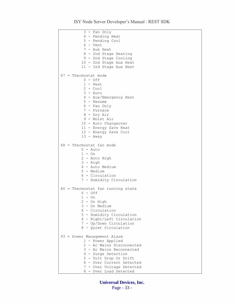
3 - Fan Only
4 - Pending Heat
5 - Pending Cool
6 - Vent
7 - Aux Heat
8 - 2nd Stage Heating
9 - 2nd Stage Cooling
10 - 2nd Stage Aux Heat
11 - 3rd Stage Aux Heat
67 = Thermostat mode
0 - Off
1 - Heat
2 - Cool
3 - Auto
4 - Aux/Emergency Heat
5 - Resume
6 - Fan Only
7 - Furnace
8 - Dry Air
9 - Moist Air
10 - Auto Changeover
11 - Energy Save Heat
12 - Energy Save Cool
13 - Away
68 = Thermostat fan mode
0 - Auto
1 - On
2 - Auto High
3 - High
4 - Auto Medium
5 - Medium
6 - Circulation
7 - Humidity Circulation
80 = Thermostat fan running state
0 - Off
1 - On
2 - On High
3 - On Medium
4 – Circulation
5 - Humidity Circulation
6 - Right/Left Circulation
7 - Up/Down Circulation
8 - Quiet Circulation
93 = Power Management Alarm
1 - Power Applied
2 - Ac Mains Disconnected
3 - Ac Mains Reconnected
4 - Surge Detection
5 - Volt Drop Or Drift
6 - Over Current Detected
7 - Over Voltage Detected
8 - Over Load Detected

ISY Node Server Developer’s Manual : REST SDK
Universal Devices, Inc.
Page - 34 -
9 - Load Error
10 - Replace Battery Soon
11 - Replace Battery Now
12 - Battery Is Charging
13 - Battery Is Fully Charged
14 - Charge Battery Soon
15 - Charge Battery Now
94 = Appliance Alarm
1 - Program Started
2 - Program In Progress
3 - Program Completed
4 - Replace Main Filter
5 - Failure To Set Target Temperature
6 - Supplying Water
7 - Water Supply Failure
8 - Boiling
9 - Boiling Failure
10 - Washing
11 - Washing Failure
12 - Rinsing
13 - Rinsing Failure
14 - Draining
15 - Draining Failure
16 - Spinning
17 - Spinning Failure
18 - Drying
19 - Drying Failure
20 - Fan Failure
21 - Compressor Failure
95 = Home Health Alarm
1 - Leaving Bed
2 - Sitting On Bed
3 - Lying On Bed
4 - Posture Changed
5 - Sitting On Edge Of Bed
96 = VOC Level
1 - Clean
2 - Slightly Polluted
3 - Moderately Polluted
4 - Highly Polluted
97 = Barrier Status
0 - Closed
1-99 - Percent Closed (1% = almost Closed, 99% = almost Open)
100 - Open
101 - Unknown
102 - Stopped
103 - Closing
104 – Opening
98 = Insteon Thermostat mode
0 - Off
1 - Heat

ISY Node Server Developer’s Manual : REST SDK
Universal Devices, Inc.
Page - 35 -
2 - Cool
3 - Auto
4 – Fan Only
5 – Program Auto
6 – Program Heat
7 – Program Cool
99 = Insteon Thermostat fan mode
7 – On
8 - Auto

ISY Node Server Developer’s Manual : REST SDK
Universal Devices, Inc.
Page - 36 -