itnotice repot areillegible,- c r ben reprced fro ben copy to permit the broadest t ability....
TRANSCRIPT

NOTICEREPOT AREILLEGIBLE,- C
r ben reprced fro ben
copy to permit the broadest tability.
ANL-82-64
Distribution Category:LMFBR-Physics: Base
Technology (UC-- 79d )
ANL--82-64
DE84 012678
ARGONNE NATIONAL LABORATORY9700 South Casa Avenue
Argonne, Illinois 60439
DIF3D: A CODE TO SOLVEONE-, TWO-, AND THREE-DIMENSIONAL
FINITE-DIFFERENCE DIFFUSION THEORY PROBLEMS
by
K. L. Derstine
Applied Physics Division
April 1984
isTh
IIeej'
FR~I~i
""'IT"
OF IIUS DOCUMENT IS UNITE
I

UA major purpose of the Techni-
cal Information Center is to providethe broadest dissemination possi-ble of information contained inDOE's Research and DevelopmentReports to business, industry, theacademic community, and federal,state and local governments.
Although a small portion of thisreport is not reproducible, it isbeing made available to expeditethe availability of information on theresearch discussed herein. '
TABLE OF CONTENTS
Page
PROGRAM ABSTRACT . . . . . . . . . . . . . . . . . . . . . . . . . . . . xii
ABSTRACT . . . .1
1. INTRODUCTION . . . . . . . . . . . . . . . . . . . . . . . . . . . . 2
2. NEUTRONICS EQUATIONS AND SOLUTION METHODS . . . . . . . . . . . . . 5
2.1 Derivation of the Mesh-Centered Finite-Difference Equations . 5
2.1.1 The Multidimensional Multigroup Neutron DiffusionEquations . . . . . . . . . . . . . . . . . . . . . . 5
2.1.2 The Orthogonal XYZ Geometry Derivation . . . . . . . . 62.1.3 Comments Regarding All Geometry Options . . . . . . . 102.1.4 The Matrix Equations and Their Properties . . . . . . 16
2.2 Solution Strategies . . . . . . . . . . . . . . . . . . . . . 19
2.2.1 The Chebyshev Accelerated Outer (Fission Source)Iterations . . . . . . . . . . . . . . . . . . . . . . 20
2.2.2 The Line Successive Overrelaxation of the Inner
Iterations . . . . . . . . . . . . . . . . . . . . . . 252.2.3 Outer Iteration Computational Considerations . . . . . 282.2.4 Inner Iteration Computational Considerations . . . . . 30
2.2.5 Data Management Considerations . . . . . . . . . . . . 38
2.2.6 Adjoint Solution Strategy . . . . . . . . . . . . . . 39
2.2.7 Upscatter Iteration Strategy . . . . . . . . . . . . . 40
2.2.8 The Inhomogeneous Problem . . . . . . . . . . . . . . 41
2.3 The Criticality Search Option . . . . . . . . . . . . . . . . 43
2.3.1 Statement of the Problem . . . . . . . . . . . . . . . 43
2.3.2 Method of Solution . . . . . . . . . . . . . . . . . . 44
2.3.3 Comments on the Concentration Search Option . . . . . 45
2.4 Summary . . . . . . . . . . . . . . . . . . . . . . . . . . . 47
3. A GUIDE FOR USER APPLICATIONS . . . . . . . . . . . . . . . . ... 48
3.1 Setting Up a DIF3D Job - An Overview . . . . . . . . . . . . . 48
3.1.1 Input Binary Files . . . . . . . . . . . . . . . . . . 48
3.1.2 BCD Card-Image Model Input . . . . . . . . . . . . . . 48
3.1.3 BCD Card-Image Calculation Parameter Input . . . . . . 493.1.4 Edits . . . . . . . . . . . . . . . . . . . . . . . . 49
3.2 BCDInput Conventions . . . . . . . . . . . . . . . . . . . . 49
3.2.1 BLOCK= . . . . . . . . . . . . . . . . . . . . . . . . 50
3.2.2 DATASET-, UNFORM-, NOSORT- . . . . . . . . . . . . . . 50
3.2.3 BLOCK-OLD. . . . . . . . . . . . . . . . . . . . . . . 52
3.2.4 MODIFY-, REMOVE-, rn-DELETE . . . . . . . . . . . . . 52
3.2.5 Sample Input . . . . . . . . . . . . . . . . . . . . . 53
3.2.6 Output from BCD Input Card Preprocessors . . . . . . . 53
iii

TABLE OF CONTENTS (cont.)
Page
3.3 General Philosophy on Input Data . . . . . . . . . . . . . . . 53
3.4 Free-Format (FFORM) Syntax Rules . . . . . . . . . . . . . . 55
3.4.1 Delimiters . . . . . . . . . . . . . . . . . . . . . . 55
3.4.2 Data Forms . . . . . . . . . . . . . . . . . . . . . . 55
3.4.3 Implied Blanks and Zeroes . . . . . . . . . . . . . . 56
3.4.4 nR, the Repeat Option . . . . . . . . . . . . . . . . 56
3.4.5 $, End of Card . . . . . . . . . . . . . . . . . . . . 56
3.4.6 UNFORM and Card Type Numbers . . . . . . . . . . . . . 57
3.5 Microscopic Cross Sections - ISOTXS, XS.ISO and A.ISO . . . . 57
3.5.1 Reaction Versus Production Based (n,2n) CrossSections . . . . . . . . . . . . . . . . . . . . . . . 57
3.6 Number Densities, Cross Section Homogenization and Edits . . . 58
3.6.1 Compositions, Zones and Subzones - A.NIP3 13 and14 Cards . . . . . . . . . . . . . . . . . . . . . . . 58
3.6.2 Isotope Sets - A.NIP3 39 Cards . . . . . . . . . . . . 59
3.6.3 Homogenization of Principal Cross Sections . . . . . . 593.6.4 Homogenization of the Scattering Cross Section . . . . 603.6.5 Discussion of the Removal Cross Section . . . . . . . 623.6.6 Homogenization Options for the Fission Spectrum -
A.HMG4C 02 Card . . . . . . . . . . . . . . . . . . . 62
3.6.7 Edit Options and Container Storage - A.HMG4C 02 Card . 633.6.8 Directional Diffusion Coefficient Factors -
A.NIP3 35 and 36 Cards . . . . . . . . . . . . . . . . 64
3.6.9 Fission and Capture Energy Conversion Factor Data -A.NIP3 37 and 38 Cards . . . . . . . . . . . . . . . . 64
3.7 Geometry Input and Edits - A.NIP3 and GEODST . . . . . . . . . 64
3.7.1 Geometry Types - A.NIP3 03 Card . . . . . . . . . . . 65
3.7.2 Boundary Conditions - A.NIP3 04, 05, 10, 11 and31 Cards . . . . . . . . . . . . . . . . . . . . . . . 65
3.7.3 Regions and Areas - A.NIP3 06, 07, 15, 30 and31 Cards . . . . . . . . . . . . . . . . . . . . . . . 66
3.7.4 Mesh-Spacing - A.NIP3 06, 09 and 29 Cards . . . . . . 663.7.5 Bucklings - A.NIP3 12 and 34 Cards . . . . . . . . . . 66
3.7.6 Geometry Edits - A.NIP3 02 and 43, A.DIF3D 04 Cards . 67
3.8 Distributed, Inhomogeneous Sources - A.NIP3, FIXSRC andA. DIF3D . . . . . . . . . . . . . . . . . . . . . . . . . . . 67
3.8.1 By Group, By Region or Mesh - A.NIP3 19 Cards . . . . 673.8.2 Synthesis Trial Function Source - A.NIP3 40 Card . . . 673.8.3 Natural Decay Source - A.NIP3 41 and 42 Cards . . . . 673.8.4 Source Edits - A.NIP3 40Card . . . . . . . . . . . . 68
3.9 Code Dependent Input - A.DIF3D . . . . . . . . . . . . . . . . 68
3.9.1 Data Aanagement Options and Container Sizes -A.DI3D 02 Card . . . . . . . . . . . . . . . . . . . 68
iv

TABLE OF CONTENTS (cont.)
Page
3.9.2 Solution Options and Control Parameters -A.DIF3D 03 Card . . . . . . . . . . . . . . . . . . . 72
3.9.3 Convergence Criteria - A.DIF3D 05 and 06 Cards . . . . 723.9.4 Edit Options and Interface File Output -
A.DIF3D 04 Card . . . . . . . . . . . . . . . . . . . 73
3.9.5 Restart Option - A.DIF3P 03, 06 and 07 Cards . . . . . 753.9.6 Acceleration of Near-Critical Source Problems -
A.DIF3D 08 Card . . . . . . . . . . . . . . . . . . . 75
3.9.7 Neutron Transport Option - A.DIF3D 09 Card . . . . . . 75
3.10 Guidelines for the Efficient Use of the CIIS . . . . . . . . . 75
3.10.1 Optimal ECM Size Estimation - A.DIF3D 02 Card . . . . 76
3.11 Criticality Search Input and Edits . . . . . . . . . . . . . . 79
3.11.1 Parametric Modifiers M - A.NIP3 23-26 Cards. . . . . . 803.11.2 Search Parameter Estimates x - A.NIP3 22 Card . . . . 803.11.3 Search Pass Control Parameters - A.NIP3 21 Card . . . 803.11.4 Search Restarts - A.NIP3 21 and 22 Cards . . . . . . . 813.11.5 Search Edits - A.NIP3 21 Card . . . . . . . . . . . . 81
3.12 Running DIF3D . . . . . . . . . . . . . . . . . . . . . . . . 81
3.12.1 Input and Output Interface Datasets . . . . . . . . . 81
3.12.2 Sample Input . . . . . . . . . . . . . . . . . . . . . 81
3.12.3 IBM Considerations - ARCSPO21 Symbolic Parameters . . 833.12.4 CDC 7600 Considerations. . . . . . . . . . . . . . . . 87
3.12.5 Multiple Problems and Restarts - RTFLUX and DIF3D . . 89
3.13 LASIP3 CCCC Standard Interface File Processor . . . . . . . . 90
3.14 Definitions of Output Integral Quantities . . . . . . . . . . 90
3.14.1 Iteration History Quantities . . . . . . . . . . . . . 90
3.14.2 Preliminary Definitions of Integral Forms . . . . . . 923.14.3 Region and Mesh Cell Flux Integrals . . . . . . . . . 95
3.14.4 Region-Averaged Flux Integrals . . . . . . . . . . . . 97
3.14.5 Zone-Averaged Flux Integrals (RZFLUX) . . . . . . . . 973.14.6 Region and Mesh Power Density Integrals (PWDINT) . . . 983.14.7 Region and Group Balance Integral Components . . . . . 99
3.15 Signs of Trouble . . . . . . . . . . . . . . . . . . . . . . . 103
3.15.1 Error Messages . . . . . . . . . . . . . . . . . . . . 103
3.15.2 Non-monotonic Convergence . . . . . . . . . . . . . . 103
3.16 Special DIU3D Applications . . . . . . . . . . . . . . . . . . 107
3.16.1 Perturuition Theory - VARI3D . . . . . . . . . . . . . 107
3.16.2 Fuel Cycle Analysis - REBUS-3 . . . . . . . . . . . . 107
3.16.3 Calculating Higher Harmonics . . . . . . . . . . . . . 107
3.16.4 Calculating Electrostatic Potential Distributions . . 1083.16.5 Neutron Transport with Isotropic Scattering . . . . . 108
V

TABLE OF CONTENTS (cont.)
Page
4. PROGRAMMING INFORMATION . . . . . . . . . . . . . . .
4.1 Role and Function of Subprograms . . . . . . . . . . . . . .
4.1.1 Module and Overlay Driver - STPO21 (D3DRIV) . . . .
4.1.2 Input Preprocessors - SCAN and STUFF. . . . . . . .4.1.3 CSE010 (ANL only). . . . . . . . . . . . . . . . . .
4.1.4 LASIP3 (ANL only). . . . .-. . . . . . . . . . . . .
4.1.5 The General Input Processor - GNIP4C . . . . . . . .4.1.6 Cross Section Homogenization - HMG4C . . . . . . . .4.1.7 MODCXS . . . . . . . . . . . . . . . . . . . . . . .
4.1.8 BCDINP . . . . . . . . . . . . . . . . . . . . .
4.1.9 SRCH4C . . . . . . . . . . . . . . . . . . . . . . . .
4.1.10 D IF 3D . . . . . . . . . . . . . . . . . . . . . . . .
4.1.11 Summary (ANL only) . . . . . . . . . . . . . . .
4.1.12 UDOIT1-UDOIT3 . . . . . . . . . . . . . . . . .
4.2 Data Set Classification and Use by Code Block . . . . .
4.3 Data Management Considerations . . . . . . . . . . . . .
4.3.1 Data Management Concepts . . . . . . . . . . . .4.3.2 Multilevel Data Management Strategy . . . . . .
4.3.2.1 The One-Group-Contained Strategy . . .4.3.2.2 Concurrent Inner Iteration Strategy . . . .4.3.2.3 Two-Level Machine Data Management
Considerations . . . . . . . . . . . . . .
4.3.3 DIF3D Data Management Routines . . . . . . . . .
4.3.3.14.3.3.24.3.3.34.3.3.44.3.3.54.3.3.64.3.3.74.3.3.84.3.3.94.3.3.10
DEFICF. . . . . . . . . . .
OPENCF. . . . . . . . . .
CLOSCF. . . . . . . . . . .
P URGCF . . . . . . . . . . .
BLKGET, FINGET, BLKPUT and FINPUTDEFIDF . . . . . . . . . . .
OPENDF and CLOSDF . . . . .PNTGET and IPTGET . . . .PCRED, ICRED, PCRIT and ICRIT . .STATCF. . . . . . . . . . .
109
109
109110112112113115115117117118124124
124
127
127128
131132
135
136
136136137137137138138139139139
139
140141142143144
144
144147147149149149
."
."
."
."
."
."
."
."
."
."
."
."
."
."
."
."
."
."
."
."
."
.S
."
."
."
."
."
."
."
."
4.3.4 CCCC Utility Routines . . . . . . . . . . . . . . .
4.3.4.1 SEEK . . .. . . . . . . . . . . . . . .
4.3.4.2 REED/RITE . . . .. . . . . . . . . . .4.3.4.3 DOPC and DRED/DRIT. . . . . . . . . . . . .
4.3.4.4 CRED/CRIT. . . . . . . . . . . . . . . .
4.3.4.5 ECMV . . . . . . . . . . . . . . . . . . . .
4.3.5 BPOINTER, a Dynamic Storage Allocation Program . . .
4.3.5.1 Programming Considerations . . . . . . .4.3.5.2 IGTLCM/IGTSCM/IGTXCM. . . . . . . . . .4.3.5.3 IBM Aiic'.ation . . . . . . . . . . . . .
4.3.5.4 CDC Allocation . . . . . . . . . . . . .
4.3.5.5 CRAY Allocation (CTSS) . . . . . . . . . .4.3.5.6 CRAY Allocation (COS) . . . . . . . . .
vi
.S
."
."
."
."
."
."
."
."
."
."
.S
."
."
."
."
."
."
."
."

TABLE OF CONTENTS (cont.)
4.4 Machine Dependence, Hardware and Software Requirements . .
4.4.1 General Considerations . . . . . . . . . . . . . .
4.4.2 Storage Requirements . . . . . . . . . . . . . . .
4.4.3 Data Access Modes . . . . . . . . . . . . . . . .
4.4.3.1 SIO, a random access, asynchronous I/Opackage for IBM systems . . . . . . . . . .
4.4.3.2 Implementation Considerations on theCDC 7600 . . . . . . . . . . . . . . . .
4.4.4 Vectorization on the CRAY-1 . . . . . . . . . . .
THE NATIONAL ENERGY SOFTWARE CENTER VERSIONS OF DIF3D . . . . .
5.1 The DIF3D Package . . . . . . . . . . . . . . . . . . .
5.1.1 File 1 - DIF3D FORTRAN Source Images . . . . . .5.1.2 Machine Dependent Source Code . . . . . . . . .5.1.3 Loader Instructions . . . . . . . . . . . . . .
5.1.4 Sample Problem Input and Output . . . . . . . .5.1.5 ARCSPO21, An Instream JCL Procedure for IBM
370 Systems . . . . . . . . . . . . . . . . . .
5.1.6 CCCC and Code-Dependent Interface FileDescriptions . . . . . . . . . . . . . . . . . .
5.2 Implementation of the NESC DIF3D as a Stand-Alone Program . .
5.2.1 Code Structure and Loading Instructions . . . .5.2.2 SIO . . . . . . . . . . . . . . . . . . . . . . . .
5.2.3 File Number Assignments . . . .. . . . . . . .
5.2.4 Running the NESC version of DIF3D . . . . . . .
5.3 Sample Problems . . . . . . . . . . . . . . . . . . . .
5.3.1 The SNR Benchmark Problem . . . . . . . . . . .
5.3.1.1 The Two-Dimensional Model . . . . . . .5.3.1.2 The Three-Dimensional Model . . . . . .
5.3.2 The IAEA Benchmark Problem . . . . . . . . . . . .
5.3.2.1 The Two-Dimensional Model . . . . . . .5.3.2.2 The Three-Dimensional Model . . . . . .
5.4 Suggested Local Modifications . . . . . . . . . . . . . .
5.4.1 SEEK Initialization . . . . . . . . . . . . . . .
5.4.2 Storage Allocation Routines . . . . . . . . . . .5.4.3 TIMER . . . . . . . . . . . . . . . . . . . . . . . . 05.4.4 GNIP4C Graphics c . . . . . . . .
5.4.5 Random Access I/O Routines DOPC, DRED and DRIT
ACKNOWLEDGEMENTS
REFERENCES
vii
Page
152
152152152
153
154
154
156
156
156158158159
159
159
159
159160160162
163
163
163167
167
167167
167
167170170170170
171
172
. . . . . . . . .
5."

TABLE OF CONTENTS (cont.)
Page
APPENDIX
A. ARCSPO21 INSTREAM JCL PROCEDURE FOR IBM 370 SYSTEMS . . . . . . . . . A-1
B. DIF3D BCD INPUT FILE DESCRIPTIONS . . . . . . . . . . . . . . . . . . B.1-1
B.l A.DIF3D . . . . . . . . . . . .
B.2 A.HMG4C . . . . . . . . . . . . .
B.3 A.ISO (See ISOTXS File Description)
"
."
."
S
"
"
."
B.4 A.NIP3 . . . . . . . . . . . . . . . .
0."
."
."
S
"
."
."
"
."
."
."
"
"
."
."
S
."
."
."
S
."
."
.S
"
"
."
."
B.1-1B.2-1B.3-1B.4-1
C. DIF3D CCCC BINARY INTERFACE FILE DESCRIPTIONS . . . . . . . . . . . . C.1-1
C.1C.2C.3C. 4C.5C. 6C. 7C.8C.9C.10
ISOTXSGEODSTNDXSRFZNATDNFIXSRCRTFLUXSEARCHATFLUXRZFLUXPWDINT
C.1-1C.2-1C.3-1C.4-1C.5-1C.6-1C.7-1C. 8-1C.9-1C.10-1
D. DIF3D CODE-DEPENDENT BINARY INTERFACE FILE DESCRIPTIONS . . . . . . . D.1-1
D.1D.2D. 3D.4D.5
COMPXSDIF3DLABELSNHFLUXNAFLUX
D.1-1D.2-1D.3-1D.4-1D.5-1
."
.S
."
."
."
E. LINK EDIT INSTRUCTIONS FOR IBM 370 SYSTEMS . . . . . . . . . . . . . E-1
F.1. SEGMENTED LOADER INSTRUCTIONS FOR SEGLINK ON THE CDC 7600 . . . . . F.1-1
F.2. TYPE 01 OVERLAY DIRECTIVES FOR THE LDR LOADER ON THE LRAM-1 . . . . F.2-1
G. SAMPLE PROBLEM OUTPUT . . . . . . . . . . . . . . . . . ....
Sample Problem 1Sample Problem 2Sample Problem 3Sample Problem 4Sample Problem 5Sample Problem 6
(entire output) . . . . . .
(selected pages) . . . . . .
(selected pages) . . . . . .
(selected pages) . . . . . . .
(selected pages) . . . . . .
(selected pages) . . . . . .
. . . G.1-1
G.1-1G.2-1G.3-1G.4-1G.5-1G. 6-1
viii
G.1G. 2G. 3G. 4G. 5G. 6
.S
."
."
."
."
."
."
."
."
."
."
."
."
."
."
."
."
."
."
."
."
."
."
."
.
."
."
."
."
."
."
."
."
."
."
."
."
."
."
."
."
."
."
."
."
."
."
."
."
.S
."
."
."
."
."
."
."
."
."
."
."
."
."
."
."
."
."
.S
."
."
."
."
."
."
.S
."
."
."
."
."
."
."
."
."
."
."
."
.S
."
."
."
."
."
."
."
."
."
.S
."
."
."
."
."
."
."
."
."
.S
."
."
."
."
."
."
."
."
."
."
."
."
."
."
."
."
."
."
."
."
."
."
."
."
."
."
."
."
."
."
."
."
."
."
."
.S
."
."
."
.S
."
."
."
."
-"
."
.S
."
."
."
."
."
."
."
."
."
."
."
."
."
."
."
."
."
."
."
."
."
."
."
."
."
.S
."
."
."
."
."
.S
."
."
."
."
."
."
."
."
."
."
."
."
."
."
."
."
."
."
.S
."
."
."
."
."
."
."
."
."
."
."
."
."
."
."
."
."
."
."
.I
."
."
.I
."
."
."
."
."
."
."
.S
."
."
."
."
."
.'
."
."
."
."
."
."
."
."
."
."
."
."
."
."
."
."
."
."
."
."
."
."
.S
."
."
."
."
."
."
."
."
."
.S
."
."
."
."
."
."
."
."
."
."
."
."
."
."
."
."
."
."
."
."
."
."
.
.
."
."
."
."
."
."
."
."
."
."
.S
."
."
."
."
.S
."
."
."
.S
.S
."
."
."
."
."
."
."
."
."
."
."
."
."
."
.I
."
."
."
."
."
."
."
."
."
.S
."
."
."
."
."
."
."
."
."
."
."
."
."
."
."
."
."
."
."
."
."
."
."
."
.S
."
."
."
."
."
."
."
."
."
.S
."
."
."
."
."
."
.S
."
."
."
."
."
."
."
."
."
."
.S
."
.S
."
."
."
."
.S
."
."
."
."
.S
."
.S
.S
."
.S
."
."
."
."
.S
."
."
."
."
.S
."
."
."
."
.S
."
."
."
."
."
."
."
."
."
."
."
.S
."
."
."
."
."
."
."
."
."
."
."
.I
."
."
."
."
."
."
."
."
."
."
."
.S
."
."
.S
."
."
LIST OF FIGURES
No.
1.1
2.1
2.2
2.3
2.4
2.5
Major Modules in the DIF3D Standard Path STPO21 .
X-Y-Z Volume Element . . . . . . . . . . . . .
O-R-Z Volume Element . . . . . . . . . . . . .
Triangular-Z Volume Elements . . . . . . . . .
Parallelogram Boundary Domain (1200 planar symmetry)
L P 0l.l.LrJ6L a iu IIJL r n d J.nU L n J (6 LL JmL r. )
2.6 Rectangular Boundary Domain (90*, 1800 or 3600 p
3.1 Illustration of Input Conventions . . . .
3.2 A Data Management Page Edit for Sample Problem 4
3.3 Iteration History Page Edit for Sample Problem 1
3.4 CIIS ECM Storage Requirements Guid . . .
3.5 ANL DIF3D Input Skeleton for Sample Problem 1
3.6 Minimal Input Data Example . . . . . . . .
3.7 LASIP-3 Input Skeleton . . . . . . . . . .
3.8 Structure of Job Deck for CDC 7600 at LBL . .
3.9 Structure of Job Deck for CDC 7600 at BNL . .
4.1 An Example of the Use of SCAN and STUFF . .
4.2 Subroutine Map for the GNIP4C Code Block . .
4.3 Subroutine Map for the HMG4C Code Block . .
4.4 Subroutine Map for the DIF3D Code Block . .
4.5 Multilevel Data Transfer Paths . . . . . . .
4.6 Concurrent Inner Iteration Algorithm . . . .
4.7 Concurrent Inner Iteration I/O Cycle Description
4.8 A BPOINTER Example . . . . . . . . . . . . .
4.9 IGTSCM/FRESCM/LOCFWD Example . . . . . . . .
. . . . . . . .
. . . . . . . .
. . . . . . . .
. . . . . . . .
. . . . . . . .
. . . . . . . .
lanar symmetry). . .
. . . . . . . . . .
. . . . . . . . . .
. . . . . . . . . .
. . . . . . . . . .
. . . . . . . . . .
. . . . . . . . . .
. . . . . . . . . .
. . . . . . . . . .
. . . . . . . . . .
. . . . . . . ,. . .
. . . . . . . . .
. . . . . . . . . .
. . . . . . . . . .
. . . . . . . . . .
. . .
(L-3,
. . . . . . .
U=2) . . . .
. . . . . . . . . .
. . . . . . . . . .
ix
Page
4
13
13
14
14
15
15
'54
71
74
78
82
84
84
88
88
111
114
116
119
129
133
134
146
148
ra ei~tg ogam ou arLL y miikV il yU ]Xet
LIST OF FIGURES
No. Page
4.10 Fast-Core Allocation on IBM and CDC 7600 Machines . . . . . . . . . 150
4.11 Fast-Core Allocation on a CRAY MA . . . . . . . . . . . . . . 151
5.1 Input Data for the Four 5R Benchmark Problem Models . . . . . . . . 165
5.2 Input Data for the IAEA Benchmark Problem Models . . . . . . . . . . 168
x
LIST OF TABLES
No.
2.1 Mesh-Centered Finite-Difference Formulas . . . . . . . .
2.2 Areas and Volumes for Each Geometry Option . . . . . . .
3.1 Microscopic Cross Section Assignments to Macroscopic Cross
3.2 A.DIF3D FCM and ECM Minimum Container Size Estimation . .
3.3 ECM Size Estimation for the CIIS . . . . . . . . . . . .
3.4 DIF3D Interface Files (CCCC and code dependent) . . . .
3.5 Job Region Size and Dataset Space Estimation for ARCSPO21
3.6 Inner Iteration Error Reduction Effects for the SNRBenchmark Problem . . . . . . . . . . . . . . . . . . .
3.7 Inner Iteration Error Reduction Effects for the LCCEWGBenchmark Problem . . . . . . . . . . . . . . . . . . .
3.8 Inner Iteration Error Reduction Effects for a ZPPR 11(B) M
4.1 Data Set Classification and Description . . . . . .
4.2 Interface File Usage by Module . . . . . . . . . . .
4.3 Random Access File Descriptions . . . . . . . . . . .
4.4 Correspondence Between ECM and Disk Files . . . . .
4.5 Execution Rates for the 2D IAEA Benchmark . . . . . .
5.1 DIF3D Tape Characteristics and its BCD File Contents . . .
5.2a Contents of NESC Export Tape for IBM 370 Systems . . .
5.2b Contents of NESC Export Tape for CDC 7600 Systems . . . .
5.2c Contents of NESC Export Tape for CRAY-1 Systems . . .
5.3 DIF3D Code Blocks . . . . . . . . . . . . . . . . . .
5.4 Data Set Classification for the NESC DIF3D . . . . . .
. .
odel
5.5 Resource Estimates for Sample Problems 1-6 . . . . . . . . . . . .
xi
. . . . .
Sections.
. . . . .
. . . . .
. . . . .
. ." ." ." ."
. ." ." ." ."
. . .
. ." ."
Page
11
12
61
70
77
82
85
104
105
106
125
126
130
130
155
156
157
157
157
158
161
164
. . . . .
. . . . .
. . . . .
. . . . .
. . . . .
. . . . .
. . . . .
. . . . .
. ." ." ." ."
. ." ." ." ."
. ." ." ." ."

PROGRAM ABSTRACT
1. Name of Program: DIF3D 4.0
2. Computer for which Program is Designed and Other Machine VersionPackages Available: IBM 370 series, CDC 7600 and CRAY-1 computers.
3. Description of Problem Solved: DIF3D solves multigroup diffusiontheory eigenvalue, adjoint, fixed source and cricicality (concentrationsearch) problems in 1-, 2- and 3-space dimensions for orthogonal (rec-tangular or cylindrical), triangular and hexagonal geometries.Anisotropic diffusion coefficients are permitted. Flux and power den-sity maps by mesh cell and regionwise balance integrals are provided.Although primarily designed for fast reactor problems, upscattering andinternal black boundary conditions are also treated.
4. Method of Solution: Mesh-centered finite-difference equations aresolved by optimized iteration methods 1 ,2 . A variant of the Chebyshevsemi-iterative acceleration technique is applied to outer (fission-source) iterations and an optimized block-successive-overrelaxationmethod is applied to the within-group iterations. Optimum overrelaxa-tion factors are precomputed for each energy group prior to the initia-tion of the outer iterations. The forward sweep of the LU decomposi-tion algorithm for the resulting tridiagonal matrices is computed priorto outer iteration initiation in orthogonal non-periodic geometrycases.
In two- and three-dimensional hexagonal geometries the neutron dif-fusion equation is solved using a nodal scheme3-5 with one mesh cell(node) per hexagonal assembly. The nodal equations are derived usinghigher order polynomial approximations to the spatial dependence of theflux within the hexagonal node. The final equations, which are cast inresponse matrix form, involve spatial moments of the node-interior fluxdistribution plus surface-averaged partial currents across the faces ofthe node. These equations are solved using a fission source iterationwith coarse-mesh rebalance acceleration.
5. Restriction on the Complexity of the Problem: Problem dimensions areall variable. The number of mesh cells in a mesh plane is limited onlyby the available dynamic storage (see "Machine Requirements" below).In three-dimensional finite-difference problems a concurrent inneriteration strategy permits the specification cf an unlimited number ofmesh planes. Scattering is P0 only and only CHI vectors are permitted.
xii

The nodal option does not permit fixed-source problems. Enough coremust be available on IBM machines to contain all data for at least oneenergy group. On the CDC 7600 machine, problem size may be limited bythe requirement that one-group data for a single axial mesh plane fitin the available fast core memory.
6. Typical Running Time: Running time for the finite-difference calculationis roughly proportional to: flux work units (FWU) = number of spacemesh cells x number of energy groups x number of iterations per group.Depending on the options selected, rates of 4 to 8 million FWU perminute on the IBM 370/195 are typical in three-dimensional problems.CPU times on the IBM 3033 are 35 to 50% greater. than those obtained onthe IBM 370/195. CPU times on the CDC 7600 are 10 to 25% less thanthose obtained on the IBM 370/195. CPU times on the CRAY-1 with thenon-vectorized SLOR algorithm are about one-third those on the IBM370/195. The vectorized SLOR algorithm times are nearly one-fourththose on the IBM 370/195.
A three-dimensional nodal calculation with 4 energy groups and 14axial mesh planes for a fast reactor model with sixth core planar sym-metry and 17 rings of hexagons required approximately 1 CPU minute onan IBM 370/195 machine. The 6 triangle/hex finite-difference calcula-tion for this same 14-plane problem required almost 2 cpu minutes. Foraccuracy comparable to the nodal option, the finite-difference calcula-tion requires 42 mesh planes and 10 cpu minutes.
7. Unusual Features: The DIF3D nodal option uses a single meshpoint perhexagon instead of the six triangular meshpoints per hexagon typicallyemployed in fast reactor finite difference calculations. The higher-order axia' approximation4 5 permits the use of coarse axial mesheswithout sacrificing accuracy. The nodal coupling coefficients are pre-computed and stored only for unique nodes.
DIF3D strictly adheres to the CCCC (Ref. 6) code standards and readsand writes CCCC interface datasets. For the finite-difference optionmore accurate peak power and peak flux edits are obtained by optionallycalculating average power and flux values on mesh cell surfaces. Thesurface fluxes are obtained in a manner consistent with the mesh-centered finite-difference approximation.
8. Related or Auxiliary Programs: This is a stand-alone version of theDIF3D module described in Ref. 1-5. DIF3D is included in the REBUS-3(Ref. 7) code package, and can thus be used to provide the neutronicssolutions required in the REBUS-3 depletion calculations.
9. Status: The modular version of the code is in production use atArgonne. The standalone CDC 7600 and CRAY-1 versions of DIF3D are inproduction use at other laboratories.
10. References:
1. D. R. Ferguson and K. L. Derstine, "Optimized Iteration Strategiesand Data Management Considerations for Fast Reactor FiniteDifference Diffusion Theory Codes," Nucl. Sci. Eng., 64, 593 '(1977).
xiii

2. K. L. Derstine,"DIF3D: A Code to Solve One-, Two-, andThree-Dimensional Finite Difference Diffusion Theory Problems,"ANL-82-64,Argonne National Laboratory, 1984.
3. R. D. Lawrence, "A Nodal Interface Current Method for MultigroupDiffusion Calculations in Hexagonal Geometry," Trans. Am. Nucl.Soc., 39, 461 (1981).
4. R. D. Lawrence, "A Nodal Method for Three-Dimensional Fast ReactorCalculations in Hexagonal Geometry," Proceedings of the TopicalMeeting on Advances in Reactor Computations, Vol. II, p. 1030, SaltLake City, American Nuclear Society, March, 1983.
5. R. D. Lawrence, "The DIF3D Nodal Neutronics Option for Two- andThree-Dimensional Diffusion Theory Calculations in HexagonalGeometry," ANL-83-1, Argonne National Laboratory, 1983.
6. R. Douglas O'Dell, "Standard Interface Files and Procedures forReactor Physics Codes, Version IV," UC-32 Los Alamos ScientificLaboratory (September 1977).
7. B. J. Toppel, "The Fuel Cycle Analysis Capability, REBUS-3,"ANL-83-2, Argonne National Laboratory, 1983.
11. Machine Requirements: At least 325K-bytes of core storage are recom-mended for program and file buffer storage on the IBM 370 series.Between 30000 and 40000 words of SCM are required on the CDC 7600depending upon the operating system employed. Additional (LCM on CDC)memory requirements expand linearly with the number of cells (N) in amesh plane. The finite-difference option requires at least 9N (8-byte)words in 2-D problems and at least 25N words are required in 3-D prob-lems. At least 19 mesh lines of data and one group of cross sectiondata must be stored in SCM on the CDC 7600. External data storage mustbe available for approximately 40 scratch and interface files.Fourteen of these are random access scratch files (grouped into 6 filegroups), the remainder are sequential access files w'th formatted orunformatted record types.
12. ProgrammingLanguages Used: The standard FORTRAN described in ANSS0D.3-1971 is used. The program can be executed entirely in FORTRAN,except for dynamic memory allocation routines on IBM and CDC computers,random access I/O routines on IBM computers, and LCM/SCM transfer rout-ines on the CDC 7600. The exceptions noted above are either written inassembly language or supplied from the CDC or CRAY system libraries.Thus non-Fortran code is about 2% of the IBM package and about .2% ofthe CDC and CRAY package.
13. Operating System: No special requirements are made of the operatingsystem. The IBM linkage editor and the CDC or CRAY-1 overlay or seg-mented loading facilities may be used. Random access I/O data filesshould be supported for efficient operation, but they are not necessaryfor correct operation.
xiv

14. Other Programming or Operating Information or Restrictions: An optim-ized assembler version of the (finite-difference) tridiagonal matrixsolution and overrelaxation routine is available for the CDC andCRAY systems. DIF3D is maintained as a single unified source file.Particular machine versions are configured at distribution time viaactivation and deactivation of coding bracketted by in-stream languageflag comment cards.
15. Name and Establishment of Authors:K. L. Derstine and R. D. LawrenceApplied Physics DivisionArgonne National LaboratoryArgonne, Illinois 60439
Major contributions to the finite-difference option of DIF3D were madeby D. R. Ferguson.
16. Material Available: Restricted Distribution Magnetic Tape Transmittal
a) User's Manual
b) Magnetic Tape Containing
i) Source Code
ii) Sample Problem Data Card-Images
iii) Sample Problem Output
iv) Code Dependent BCD and Binary Card-Image File Descriptions
v) Linkage Editor, Segmented Loader or Overlay Loader ControlCard-Images
vi) JCL Procedure for Execution.
17. Category: C
Keywords: block overrelaxationchebyshev accelerationcoarse mesh diffusion theoryhexagonal geometrymultigroup diffusion theorynodal diffusion theory
18. Sponsor: Division of Reactor Research and Technology, U. S. Departmentof Energy
xv

1
DIF3D: A Code to Solve One-, Two-, and Three-dimensionalFinite-difference Diffusion Theory Problem,
by
K. L. Derstine
ABSTRACT
The mathematical development and numerical solution of the finite-differenceequations are summarized. The report provides a guide for user applicationand details the programming structure of DIF3D. Guidelines are included forimplementing the DIF3D export package on several large scale computers.
Optimized iteration methods for the solution of large-scale fast-reactorfinite-difference diffusion theory calculations are presented, along withtheir theoretical basis. The computational and data management considerationsthat went into their formulation are discussed. The methods utilized includea variant of the Chebyshev acceleration technique applied to the outer fissionsource iterations and an optimiLed block successive overrelaxation method forthe within-group iterations.
A nodal solution option intended for analysis of LMFBR designs in two- andthree-dimensional hexagonal geometries is incorporated in the DIF3D packageand is documented in a companion report, ANL-83-1.

2
1. INTRODUCTION
This report is a user's manual for DIF3D, a computer code which uses themesh-centered finite-difference approximation to obtain numerical solutions of
the multigroup diffusion equations in one-, two- or three-dimensions for fastreactor applications. Although two mesh-centered finite-difference codes 3DB(Ref. 8) and VENTURE (Ref. 9) were already in existence, DIF3D (Ref. 1) waswritten to employ the more rigorous strategies of the well-known PDQ-7(Ref. 10) code. This decision was based on a thorough intercomparison of sev-
eral iterative strategies, the results1 1 of which indicated the iterativemethod employed by PDQ-7 (Refs. 12 and 13), when modified to take advantage ofseveral unique aspects of fast reactor diffusion theory calculations, is alsohighly efficient when applied to fast reactor calculations. Significantefforts were concurrently expended to provide efficient, yet flexible, datamanagement and data structures in DIF3D. The numerical results in Ref. 1demonstrate the efficiency achieved by these methods.
User interaction with the DIF3D acceleration and data management strategiesprincipally involves only two parameters; Ein, the inner iteration errorreduction factor, and ECMSIZ, the ECM container size. For most problems the
cin default is suitable and ECMSIZ is readily estimated. Optimizing thejob cost for a class of similar problems involves only a simple adjustmentto cin and ECMSIZ.
Incorporated in DIF3D for the solution of two- and three-dimensionalhexagonal geometry problems is a nodal option that uses input data virtuallyidentical to that of the finite-difference option. Reference 5 discusses themathematical development and numerical solution of the nodal equations; somenumerical comparisons between the nodal and finite-difference options fortypical heterogeneous core LMFBR designs have shown that the accuracy of thenodal solution is superior to that of a standard (6 mesh cells per hexagon,5 cm axial mesh) finite difference calculation, and that this improved accuracyis achieved with a potential order-of-magnitude reduction in computationalcost for a three-dimensional calculation.
DIF3D was developed at Argonne National Laboratory and is operational onboth the IBM 370/195 and the IBM 3033 computers, and is a principal module inthe ARC System providing eigenvalue and flux calculations for the burnup codeREBUS-3 (Ref. 7), the perturbation theory code VARI3D14 and the flux
synthesis code SYN3D15 in addition to performing standalone neutronics cal-culations including nuclide concentration searches. The programming adheresstrictly to the conventions set forth by the Committee on Computer CodeCoordination6 (CCCC). Most of the data for a calculation must be supplied in
the format of the Standard Interface Files6 defined by the CCCC. BCD inputdata (when it is required) is limited to data that is essential for theproblem (i.e. redundant information is not required), and this data may bereadily specified in free format. Particular attention has been paid tomaintaining a single unified source in which language flag comment cardssegregate code by particular and generic machine environments. A simplepreprocessor code activates or deactivates language flags appropriate to thetarget machine environment. The portability afforded by this approach isdemonstrated by the relative ease to which DIF3D is now exported and currentlyoperational in standalone form on IBM 370 series computers, on CDC 7600computers and on CRAY-1 computers.

3
The computational efficiency and data management flexibility (achievedwith minimal user control), the user-oriented input data philosophy and thehighly portable export package combine to make DIF3D an efficient computationaltool that is a standard for the LMFBR community. Thermal reactor applicationsare routinely solved with DIF3D, also.
An overview of the major code block (modules) in the DIF3D package is pro-vided in Fig. 1.1. DIF3D features are summarized in the code abstract on pagexii. This report is organized into 5 sections. Section 2 provides users withthe mathematical and computational aspects that strongly influenced the imple-mentation of the optimized iteration strategies in DIF3D. Sections 3 and 4respectively provide user and programmer information. Section 5 is intendedfor users who have just received DIF3D from the National Energy SoftwareCenter (NESC) and who are faced with the task of making the code operationalon their machine; it describes the contents of the NESC td;:s and outlinesthe steps necessary to implement DIF3D in stand-alone form on .'e IBM 370series, the CDC 7600 and the CRAY-1 computers.

4
BCD CARDS
BCD CARDS
ARC ORSPOOLING (SCAN)FTOS
BCD CARDS
.DIF30, A. ISO, PROC ESSING (ST UFF )A.HMG4C, A. NIPS,
A. L ASIP3, A.U00O T
NE BLOCK F EXIT
T
USER MULE
XS.ISO.- - . -
CROSS SECTIONCONVERSION (CSEIO)
ISOTXS
A. LAS,P3
BC BINARYCCCC FIE PROCESSOR
GEODST , NDX SRF , IL ASIP3
1STXS, ZNATDN---J
A. ISO
A. NIPSNEUTRONICS INPUT
GEODST, FIXSRC, PROCESSING (GNIP4C)ISOTXS, NDXSRF,EARCH, ZNATON
AHMG4C, A NIP,ISOTXS, NDSRF,
ZNATDN CROSS SECTIONHOMOGENIZATION
( HMGC ,MODCX SICOMPXS
A. DIFSODIF30 DIFSD CONTROL
FILE PROCESSING(S CDINP I
ISOT xS, NDxSRF,SE ARCH, ZNA TDM
CRITICAL IT Y SE ARCH(SRCH4CI --
NDXSRF.SEARCH,COYPU S
USER MODULE 2
1 30 Fix0C,(UOIT21COYPUS, GEDST ,TFLUX, SEARCH NEUTRONICS
NTFLN, AitUN CALCUL ATION (OF30)
RZFLU , POINT ,CREDIT, OIF30
Is01XS, NDXRSF,SE ARCH , ZMATDM
CRIICALITY SEARCH(SRCH4C1
MDISIF , SE ARCH ,
L-----------
0ST , NOXSR, USER MODULE 3R~, $0015. -(001131
RACION RAE EDITSL SUMMAR Y
USER MODUL E 4IUOIIA)
Fig. 1.1. Major Modules in theDIF3D Standard Path STPO21

5
2. NEUTRONICS EQUATIONS AND SOLUTION METHODS
In this section, the "mesh-centered" finite-differenced form1 6 ,1 7 of themultigroup neutron ditfusion equations is presented and is accompanied by areview of the properties of these equations that permit the application of theiterative methods chosen to solve these equations. Theoretical aspects of theiterative methods are described and the computational and data managementconsiderations that strongly influence the implementation of the iterativemethods are discussed in turn. The equations which form the basis of thecriticality search are also discussed.
2.1 Derivation of the Mesh-Centered Finite-Difference Equations
The mesh-centered form of the finite-difference equations rather thanthe mesh-edged form1 0,1 3 ,18 is traditionally used in fast-reactor analysisbecause of the computational savings afforded in the calculation of theremoval and source terms in Eqs. (2.1) and (2.2).
2.1.1 The Multidimensional Multigroup Neutron Diffusion Equations
In the mesh-centered finite-difference approximation the problem domain Ris subdivided into a regular array of mesh cells such that all material inter-faces lie on mesh cell surfaces. Within any mesh cell, say R, the materialproperties are assumed homogeneous and the time-independent multigroup neutrondiffusion equation1 9 for mesh cell RL can then be written:
-V*D V$(r) + (r) = Q(r), reR , g - 1,2,...,G (2.1)
where
Qg(r) $ (r) + g (r) 4 S(r), (2.2)lg g=1 g ' - (.2
X denotes an eigenvalue, Sg(r) denotes an optional distributed source, and the
remainder of the notation is standard.1 9,*
Equation (2.1) is solved subject to the conditions that the flux andsurface-normal component of the net current be continuous across cell inter-faces, i.e.
$ (r) - 4 (r) (2.3)
n*D 9_$(r) - nD Vm(r) (2.4)
*Homogenization formulas defining the macroscopic cross section quantities
appearing in Eq. (2.1) and Eq. (2.2) are defined in Section 3.6. Note thatDIF3D permits X-vectors, only; X-matrices are not permitted.

6
for r on the interface between cells R and Rm. Similar relations hold for
the interfaces between RR and its remaining adjoining mesh cells.
Boundary conditions of the general form
aS-D * (r) + fi(r) - 0, r e R, (2.5)
are specified on cell surfaces which form part of the external boundary 3R ofR. Standard boundary conditions (e.g. zero flux, zero incoming partial currentand extrapolated) are obtained via appropriate specification of the surface-
dependent boundary constants ag and Sg in Eq. (2.5).
When Sg(r_) 0 for all I and g, Eq. (2.1), Eq. (2.2) and Eq. (2.5) define
the eigenvalue problem for which the fundamental eigenvalue (k-effective) and
eigenvector (neutron flux) are sought. Fixed source problems arise when S # 0and A is fixed at a user specified value ensuring reactor subcriticality. Thecorresponding flux solution is then sought.
Adjoint eigenvalue and fixed source problems determine the solution tothe adjoint system associated with Eq. (2.1), Eq. (2.2) and Eq. (2.5).
2.1.2 The Orthogonal XYZ Geometry Derivation
The mesh-centered finite-difference equations will be derived in XYZgeometry for RI, an arbitrary mesh cell chosen from the IxJxK parallelepipedmesh cells defined by the coordinates xi,i-1,2,...,I+1, y.,j-1,2,...,J+1 and
zk,kl1,2 ,...,K+l. The dimensions of R are denoted by
AsI - st+ 1 -s for sR (xj,yj or zk). (2.6)
Using a local coordinate system with the origin at the centroid of the meshcell, RI is defined by
Rt ERijk - {r - (x,y,z) s - (x,y or z) c[-As1/2, As1/21}
The group index will be henceforth omitted and whenever possible the singlesubscript notation I and m will denote Rijk and adjacent cell, say,
RmE Ri+ljk, respectively.
We start by integrating the neutron diffusion equation over the volume of
RR, i.e. we operate on Eq. (2.1) with
Azk/2 Ay /2 Ax1/2
f d3r *2 dz dy dx * . (2.7)rcR1 AZk1/2

7
Application of Gauss' Theorem to the integrated leakage term yields
6
d3r VDV4 (r) - J A (2.8)
where A denotes the surface areas of RR with outwardly directed surface normaln (i.e. n1 z -ux, n2 = u ,..., n6 - uZ) and us denotes a unit vector in direc-
tJon s. The resulting neutron balance equation may be written for each energygroup in the form
6
JIAR + RVR = QtVt (2.9)
p=1
where the cell-averaged values of the flux and multigroup source terms aredefined by
- d3r (r) (2.10)
and
Q 1 / d3r Q (r). (2.11)R reR Q
JP, the surface-averaged component of the net current in direction n at
surface Ap is defined by
- f dA n*V_(r). (2.12)
The solution of Eq. (2.9) clearly requires additional relationshipsbetween the leakages and the cell-averaged fluxes in Ri and its six neighbors.Such relationships are obtained by assuming:
(1) the flux varies linearly from the center of the mesh cell to themidpoints of any of its six surfaces;
(2) along each surface, AR, variations in the normal derivative to the
surface may be neglected.
These assumptions are equivalent to introducing a multidimensional Taylorseries expansion of the flux about the cell midpoint and truncating terms of0(h2) and higher.20

8
Application of assumptions (1) and (2) to Eq. (2.10), Eq. (2.11) andEq. (2.12) lead to the following approximations:
p (0,0, 0), (2.13)
(2.14)
Q0 Q0(09090 (2.14)
J J
-J (-Axi/2)
Jx(Ax /2)
J (Ax /2) J (Ax /2,0,0) - -Dax (x,0,0) (2.16)x -Ax/2
Similar equations hold for the remaining directions y (p - 3 or 4) andz (p - 5 or 6). The derivative in Eq. (2.16) is approximated by usingassumption (1). We obtain the following expression for the component ofthe net current in direction x at the boundary of cell RR:
(2.17)S( x1/2,0,0) -
-D x/2
Evaluating and equating two expressions for the x-directed current component
across the interface between cells R and Rm (e.g. J (Ax/2) and J (-Ax +1/2))
and then applying the interface conditions, Eq. (2.3) and Eq. (2.4), leads tothe following expression for the interface flux
D m/Axi
- D /Axi+ D/Axi+1
Dm i+l
+ D /Ax + Dm AX1+lm
Substitution of Eq. (2.18) into Eq. (2.17) leads to the desired expression forthe net current component:
J (Ax /2) (2.19a)- y(( - SI)
J (-Ax +1/2) (2.19b)- - Y.(m - * )
p - 1
p - 2
where
(2.15a)
(2.15b)
(2.18)
or
$ROx/2,0,0)

9
where
x Yx-m m
- x 1
Ax Axi i +l
2D + 2Dm
(2.20)
Similar equations are obtained for directions y and z.
When Axi/2 corresponds to an external boundary in cell RR or if cell
R - Ri+k is a blackness theory region, then Eq. (2.5) provides the relation
needed for determining the boundary coupling coefficient Yxb =Lm. Rewriting
Eq. (2.5) in terms of the net current we obtain
J ( Ax /2) - ( ( Axi/2,0,0). (2.21)
The flux at the cell boundary is obtained by eliminating J( Ax /2) from
Eq. (2.17) and Eq. (2.21), and solving for $g( Axi/2,0,0):
o( Ax/2,0,0)/x/Axi
DR Ax + (/z/
The general expression for the leakage term at the boundary is obtained bysubstituting Eq. (2.22) into Eq. (2.21), e.g.
J (Ax /2)
J (-Ox /2)
lab b
m
- I }
Axi 1
2D (S7aT
(2.23)
(2.24a)
Rearrangement of terms S and a permit evaluation of Eq. (2.24a) when a - 0 or8 - 0, i.e.
20Dt
lb SAx + 2aDi L
(2.24b)
(2.22)
where

10
Equation (2.13), Eq. (2.14), Eq. (2.19) and Eq. (2.23) can now be combinedto form the mesh-centered finite difference approximation to Eq. (2.9), i.e.
6
- akm m + bz4 = q, (2.25)
m #bp
where Rm is the cell adjacent to R at surface A and
aim = A Ysm (2.26)
p p
6
bV -EV +F at (2.27)
p=1
qt= Q V .(2.28)
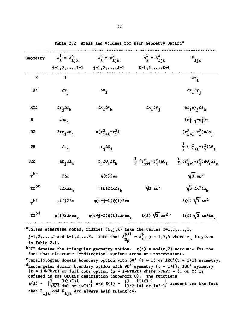
2.1.3 Comments Regarding All Geometry Options
The terms y~m and the formulas for calculating the indices mp of the P
cells R adjacent to RI are tabulated in Table 2.1 for all geometry optionstmp
in DIF3D. Table 2.2 tabulates the corresponding area and volume elements thatare illustrated in Figs. 2.1-2.3. Not included here are the two- and three-dimensional hexogonal geometry options associated with the DIF3D nodal option.5
Mesh cell numbering proceeds in a point by point, row by row and plane byplane fashion for both orthogonal and triangular geometries. Figures 2.4-2.6illustrate the mesh cell numbering for the two basic triangular geometryoptions (i.e. parallelogram or rectangular boundary domains). Includingalternately upward and downward pointing triangles in a single row, permitsthe same data structure to be used for both rectangular and triangular geometry.
The periodic boundary conditions offered by DIF3D are limited. The op-posite face periodicity option, models a repeating lattice in the "X"-directionin orthogonal geometries (i.e. RIJk is coupled to Rljk). The periodic coupling
in the 0-direction of G-R-Z geometry also fits this model.
The rotational periodicity option applies to only the lower x- and lowery-face combination which intersect at the origin in either theorthogonal or the triangular (parallelogram boundary domain only) geometryoptions. This option models the case in which the A3 surface of cells Rilk
are connected to the Am surface of Rljk where

11
Table 2.1 Mesh-Centered Finite-Difference Formulas
Orthogonal
Geometry Optionb: X,XY,XYZR, RZ, OR, ORZ
Triangular
T,TZ
S
Asc: (s + - )
1
As A
2D + 2Dm
1As k 1
2 (8C /a)
1
rj+1+ r2
1As As
3D +3DR m
1As
3D- + (/a)
s #0
s = 0
m - (i +1, j, k)
m = (i, j + 1, k)
M - (i, j, k T 1)
m - (ip
mn s (iP
1 1, j, k)
i 6, j + 1, k)e
aAxial (z-direction) formulas in TZ geometry are identical to theorthogonal case.
bCoordinates are ordered as listed (e.g. ORZ implies "X"-O, "Y"-Rand "Z"-Z.
cyVx is triangle height or 1/2 hex pitch, (2Ax = triangle sidelength).
dSign convention for mEmp: odd numbered p take minus .(-) sign,even numbered p take plus (-) sign.
eTriangular geometry offset index:-1 parallelogram boundary domain, 60 symmetry,
6 - 0 rectangular boundary domain,
1 parallelogram boundary domain, 1200 symmetry.,
p = 1 or2d
p - 3 or4d:
5 or 6d:P -s
12
Table 2.2 Areas and Volumes for Each Geometry Optiona
Geometry A = A kA Ajk A= AZ ijk=,,.+ ,,. ijk +K-, ijk,. ,
i=l,2, 0.0,1+1 j=1,2,... ,J+l K-l,2,... ,K+1
Ax i
Axi
AxiAzk Aij Ax j Azk
(r2 -r 2 )ri+l i
2rr Az
Ar Azk
2Ax
2AxAzk
j(i)2Ax
l(i) 2 AxAzk
w(r2 -r2 )i +l1i
r AtO
r CO)Azk
n(t)2x
n(t ) 2 AxAzk
n(t+j-1)(Ci)2Ax
n(t+j-1)E((i)2AxAzk
Cr2 -r? ADO2 J~l j
y3 Ax 2
VCi) Ax2J
(r2+-r 2 )irAz
1 (r2+-r 2) A
(r2 +-r 2 )AO Az2 j+1 i k
V'iAx2Azk
E(i) \ Ax2
(i) I(5'Ax 2Azk
aUnless otherwise noted, indices (i,j,k) take the values i-1,2,...,I,
j-1,2,...,J and k-1,2,...K. Note that AP+l - A, p - 1,3,5 where m is given
in Table 2.1. "p 1b"T" denotes the triangular geometry option. n(t) - mod(t,2) accounts for thefact that alternate "y-direction" surface areas are non-existant.
cParallelogram domain boundary option with 60* (t - 1) or 120*(t - 1+1) symmetry.
dRectangular domain boundary option with 900 symmetry (t - i+1), 1800 symmetry(t - i+NTHPT) or full core option (m - i+NTHPT) where NTHPT - (1 or 2) isdefined in the GEODST description (Appendix C). The functions
i ) 1 2 il1or1 I+1 and F1(() - o1/2 or I+1 account for the fact
that R1jk and RI k are always half triangles.
X 1
xY
xYz
Ay
Ay Azk
R 2'r
RZ
OR
ORZ
Tbc
TZbc
Tbd
TZbd

13
Z
~ 21 AAl
5A
--- A
-; y
Fig. 2.i. X-Y-Z Volume Element
z
I AikL
A6
32
A; I
ArA
Fig. 2.2. a-R-Z Volume Element
A3
l
A
I Azk
r

14
3 -
A +-
/ 21
A
A 1
A5~ A1 +
s-. X
Fig. 2.3. Triangular-Z Volume Elements
(1,3) (3,3) (5,3) (7,3)
(1,2) (3, 2) (5,2) (7,2)
( 2, 2) (4,2) (, (62) (8,2)
(1,1) (3,1) (5,1) (7, s)
(2, l) (4,l) (6,1) (8,1)
Fig. 2.4. Parallelogram Boundary Domain (120 planar symmetry)
A 2
6
6 Al +
00000

15
(2,3) (4,3) (6, 3) (8,3)
(1,3) 13,3) (5,13) (7,3)
(2,2) (4,2) (6,2) (8,2)
(1,2) (3,2) (5,2) (7,2).
12,1) ,\ (4,I) (6,1) (8,1)
(/I,I) (3,I) (,1) (7,1)
Fig. 2.5. Parallelogram Boundary Domain (60* planar symmetry)
Fig. 2.6. Rectangular B'undary Domain (900, 180*or 3600 planar symmetry)
(2,3) (4,3) (6,3) (8,3)
1,3) (3,3) (5,3) (7,3) 9,3)
(1,2) (3,2) (5,2) (7,2) (9,2)(
1 t ( 1 )(2,2 \ /) (4,2 ) (6 , 2 ) (8 ,24
(2,1) (4,1) /" (6,I) (8,1)
(I,1) (3,1l) (5,1) (7,1) (9,1)

16
i-i, i-1,2,...,I in orthogonal geometry;
j-(i+l)/2, i-1,3,5,... in triangular geometry (600 symmetry);
j-i/2, i-2,4,6,... in triangular geometry (1200 symmetry).
Conversely, cells Rl k are connected to Rilk where
j-1,2,...,J in orthogonal geometry;
i-2j-l, j-1,2,...,J in triangular geometry (60 symmetry);
i=2j, j-l,2,...,J in triangular geometry (120* symmetry).
2.1.4 The Matrix Equations and Their Properties
The mesh-centered finite-difference equations (Eq. (2.25) in eigenvalueform) for the cell-averaged fluxes can be written in matrix form as
([D ] + [E9fg -g' #g
[T ,]1J, - [XgJ
G
S: [F ,J,
g'-l
where * is the N-dimensional vector-g
difference mesh. The matrices [E Jmatrices defined byg
of (approximate)
[T ,J, [F J and
fluxes ou the finite
[XgJ are NxN diagonal
[E I - diag ( r 198v )
[T ,J] - diag (lr ,g5'V )
[F J - diag (vEt Vt)
IX I - diag (X4)g9
(2.30)
(2.31)
(2.32)
(2.33)
where N is the number of cells in the finite-difference mesh. The unknownsin are ordered in a linear fashion, row by row and plane by plane. Given
this linear ordering, the NxN matrix [D I contains three, five or seven
nonzero stripes for one-, two- or three-dimensional geometrics, respectively.It operates on to yield the net leakage across the faces of each mesh cell.
=j,
(2.29)
17
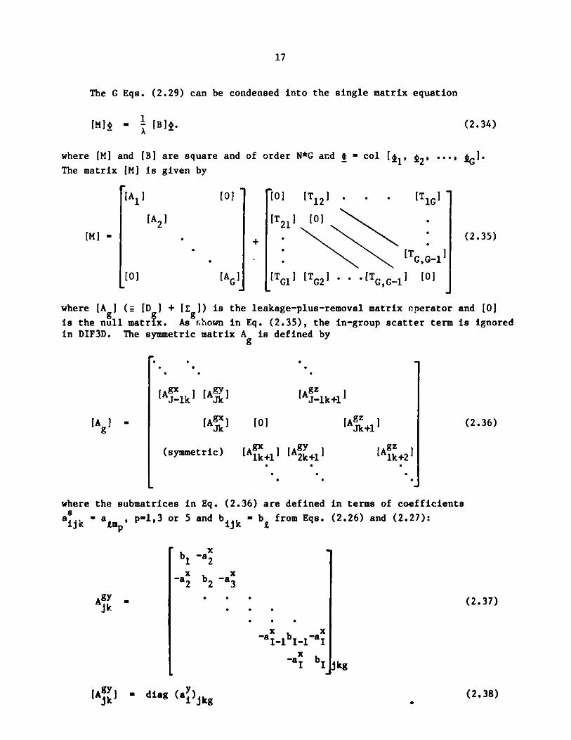
The G Eqs. (2.29) can be condensed into the single matrix equation
[Mbg - - [BJ4. (2.34)
where [M] and [B] are square and of order N*G and - col [tl, 2' ''', NG 'The matrix [MJ is given by
[01
[A2]
[AG]
+
[0] [T1 2 1 . *
[T2 1 J 0]
TG1J [TG2J .[TGG-1
[T1G
TGG-1
[0]
(2.35)
where [A ] (. [D I + [E ]) is the leakage-plus-removal matrix operator
is the null matrix. As shown in Eq. (2.35), the in-group scatter termin DIF3D. The symmetric matrix A is defined by
[A~ Jk [A YJ
[AgJ
(symmetric)
[AJ-lk+lI
[0]
[Alk1J
[AJk+l
[Ak+1
and [0]
is ignored
(2.36)
where the submatrices in Eq. (2.36) are defined in terms of coefficients
aijk - a , p-1,3 or 5 and bilk - b from Eqs. (2.26) and (2.27):
x -b- a2
-a2x-a3
.
-ax b -ax
-a1 bI I
(2.37)
jkg
[A ] - diag (a)Jkg
[Ml =
[0]
[A ] -
Ag-jk
s."
"
"
"
"
b2
*"
."
(2.38)

18
[A ]J - diag (a )jkg. (2.39)
By defining the N*G by N matrices
[F] - col[[F1 ], [F2], ..., [FG] (2.40)
and
[x] - col[[X1J, [X2], ... , [XG]1, (2.41)
the matrix [B] can be written as
[B] - [X][F]T, (2.42)
where T denotes the transpose of a matrix.
The matrices used in Eqs. (2.34)-(2.42) possess a number of propertieswhich provide a sound theoretical basis for the iteration methods which arediscussed in Sec. 2.2. For any physically realistic set of assumptions, thediagonal matrices [T ,], [X ] and [F ] are non-negative matrices. It has
gg g gbeen shown2 1 that the matrices [A I are irreducible Stieltjes matrices and that
the inverse of each [A J has all positive entries, i.e., [A J >0. Because of
these properties, the matrix [MI is nonsingular22 and the eigenvalue problemEq. (2.34) can be written as
A 0 - [M]I [BJ0. (2.43)
Under quite general conditions, Froehlich2 3 has shown that Eq. (2.43) has aunique positive eigenvector 00 and a corresponding single positive eigenvalue
X0 greater than the absolute value of any other eigenvalue of Eq. (2.43).
Furthermore any positive eigenvector of [ill [B] is a scalar multiple of [m].
The properties of [B] permit a reduction of the matrix eigenvalue problemwhich must be solved to obtain A0 from one of order N*G (Eq. (2.43)) to one ofonly order N.1 2 Advantage is taken of this fact in obtaining the outeriteration method presented in Sec. 2.2 which is used to obtain A0 and 0'
This reduction is accomplished by first noting that [MV- [BJ is of order N*Gand therefore has N*G eigenvalues. However, the rank of [F] is only N, thusmaking the rank of [M]P1 [BJ only N. Hence, (G-1)*N of its eigenvalues arezero. The nonzero eigenvalues can be determined by considering the reducedbut equivalent problem of order N.
Following Ref. 12, but considering a full scattering matrix, this reduc-tion is accomplished by first defining the fission source vector, t, as
G
S = [F]T 0- Fi ] (2.44)
g-l
and the N*G x N matrix [L] as

19
[LI - col [L1 J, [L2 ], ... , [LGJ = [M] [Xl, (2.45)
where the N x N matrices [L I are defined as
[Lg J [Ag ([X I + [T ,J[L ,]). (2.46)
g'#g gg g
These definitions plus Eq. (2.34) permit the group g flux vector jg, to bewritten as
=
= [Lg ! .(2.47)
Premultiplying Eq. (2.43) by [F]T and using Eqs. (2.42) and (2.44) yields thereduced problem
at_= [QOj, (2.48)
where
G
[0] = [FIT[L] = [FgI[Lg]. (2.49)
g=-
If I and A are an eigenvector and corresponding nonzero eigenvalue of [M] [B],then j and A must be an eigenvector and eigenvalue of [0] and vice versa.Furthermore, by making use of a similarity transformation, it has been shown1 2
that the nonzero eigenvalue spectrum of [0] is identical to the nonzero-1
spectrum of [M] [B] and that any non-negative eigenvector of [Q] is either ascalar multiple of to or else corresponds to a zero eigenvalue, where tocorresponds to AX. Thus the two eigenvalue problems, Eq. (2.43) and Eq. (2.48),are equivalent.
2.2 Solution Strategies
The finite-difference equations are solved by the well-known fission sourceiteration method24 accelerated by the Chebyshev semi-iterative method.2 5'2 6
At each fission source (or "outer") iteration, the vector of neutron fluxesfor each group is computed by solving the finite-difference equations with aknown group-dependent source term. This solution is accomplished via sucessivesweeps through the spatial mesh. Each such inner iteration sweep iterativelyinverts the leakage-plus-removal matrix operator using the line-successive-overelaxation procedure.2 7
The acceleration strategies for DIF3D are linear, well-founded and proven,and they relieve users of the burden of specifying optimum parameters for largeclasses of reactor models. Theoretical aspects of the two acceleration methodsare presented in Sections 2.2.1 and 2.2.2, respectively. Computational anddata management aspects of each method are described in Sections 2.2.3-2.2.5.The adjoint problem is discussed in Section 2.2.6. Problems with upscatteringare solved using the iteration strategy reported in Section 2.2.7. Section2.2.8 describes aspects of the inhomogeneous problem.

20
2.2.1 The Chebyshev Accelerated Outer (Fission Source) Iterations
The cuter iterations seek to determine the fundamental eigenvector, 'Z;
and corresponding eigenvalue, X0, of Eq. (2.48) or the fundamental eigenvector,
10, and a0 of Eq. (2.43). Most few-group codes, such as PDQ-7, treat the flux
problem, Eq. (2.43). This is due to two factors. First, most thermal powerreactors of interest have large reflecting regions which contain no fissionablematerials. For any outer iteration method which utilizes an outer iterationacceleration procedure such as the one described in this report, accelerationof the fission source does not markedly improve acceleration of the solutionin these reflecting regions unless much additional effort is invested in theinner iterations. This point is elaborated in Sec. 2.2.4. Second, for thetwo to four energy group structures which are typically used for thermalreactor calculations, the data storage and transfer requirements associatedwith acceleration procedures based on the fluxes are not prohibitively largerthan if the fission source were used.
In fast reactors, on the other hand, the data management requirementsassociated with accelerating the flux vector are at least an order ofmagnitude greater than those associated with the fission source for the ten tothirty energy groups which are typically used for fast reactor calculation.In addition, the fast reactor cores under consideration at the time of DIF3D'sdevelopment tended to be more tightly couple. with relatively small non-fissionable regions. Consequently, the cost of the increased number of outeriterations resulting from the fission source acceleration is more than com-pensated by the savings in I/O resources. These conclusions are borne out bythe numerical results presented in Ref. (1). Later, application to large-scale heterogeneous fast reactor core designs2 8 also proved highly efficient.
In the method reported here, approximations to A0 and 0, the fundamental
eigenvalue and eigenvector of [0], are obtained by the well-known power itera-tion method. It is assumed that the eigenvalue spectrum of [Q] satisfies
AI 1t 2t ''' IAN-l1 and that 1, is the eigenvector associated with A1 .
The power method proceeds as
(n). ( 1 (n-1) (2.50a)
i - A(n-l) [Q]J(2.0a
and
X(n) . (n-1) ii 1,2.50b)IIn-1)II
where n is the outer iteration index and. I|I| 1 denotes the L1 norm. The
actual computation of the product [Q] (nl)in Eq. (2.50a) involves anotherlevel of iteration, the inner iteration, and is discussed in the next section.A later section describes a third level of iteration, the upscatter iterationwhich occurs outside the inner iteration for all groups when upscatteringsource terms are present.

21
Because the largest (in modulus) eigenvalue of [Q] is real and simple,the power method is guaranteed to converge for any arbitrary non-negative
(0)initial vector ( to A0 and ct0, where c i some positive constant. If it
is assumed that the eigenvalue estimates a are sufficiently well converged
to 0 and that (0) can be ex a ded in terms of the i, the eigenvectors of[Q], then the rate at which n converges to to depends on the separation of
a0 from the other eigenvalues of [Q]. 12 This convergence rate depends on the
dominance ratio, a, given by
a = max 0 (2.51)i#0 X0
with the convergence rate ultimately being controlled by (a)n
The dominance ratios of large thermal power reactors typically are of theorder of 0.95 or larger, implying relatively slow convergence of the iterativeprocess given by Eq. (2.50). This fact led to the search for methods toaccelerate this convergence for thermal reactor codes, of which the accelera-tion method based on Chebyshev polynomials used by PDQ-71 2 ,1 3 and the classof methods known as coarse-mesh rebalance23 ,24 methods are the best known.Dominance ratios for large heterogeneous fast reactors can also be as large as0.95. In addition, typical fast reactor multigroup energy structures arecharacterized by nearly full downscattering matrices. The group-by-groupcalculation of the scattering source required for each outer iteration becomesa costly, input/output-bound calculation when such energy structures are usedin large multidimensional calculations. Both of these factors motivate the useof an efficient outer iteration acceleration technique in fast reactor diffusiontheory calculations.
A Chebyshev acceleration strategy similar to that used in PDQ-7 isutilized in the solution method presented here. The primary difference isthat while PDQ-7 accelerates the flux vector, 0, DIF3D accelerates the fissionsource, . The motivations for this have been presented above. Its applica-tion is cased on the assumptions that the eigenvalues of [Q] are real and non-negative and are ordered as a0 A l2 '. N-1>0 and that the eigenvectors
of [Q] form a basis for the N-dimensional vector space. Following the
derivations in Refs. 12 and 13, the basic power iteration is accelerated by
choosing a linear combination of the eigenvector iterates i (n)such that
p~(n*+p) (n*+j)
- a ,(2.52)
where n* is the outer index where this acceleration begins and p successivefission source iterates are employed. The objective is to choose the coeffi-
cients such that (n*+p)approximates j0 more closely than does J n*+p)

22
Based on the assumption of completeness, Cn*) can be written as
N-1
- ci i.
im0
(2.53)
For a sufficiently converged eigenvalue estimate _(n*), Eqs. (2.50a) and (2.53)imply that Eq. (2.52) can be written as
N-1(n*+p)
i-o
p
aj
j-0
.ifAj
0(2.54)
Letting P (x) =- a iP , Eq.
j-0
(2.54) becomes
~(n*+p)N-1
- c0 Pp(l)0 +i-i
ciP. (2.55)
The sum on the R.H.S. of Eq. (2.55) is the error. This error is minimized ina practical sense by choosing P (x) such that P (1)-1 and max P (x) is
minimized. This is accomplished by choosing P (x) in terms of Chebyshevpolynomials as2 5 p
C (-1)-
C ?- 1)
(2.56)
where the C (y) - cosh (p cosh-ly), y > 1. Given the well known recurrence
relationships for Chebyshev polynomials, the recursion relationship for P (x) is
p+l(x)2 / - 1 cosh[(p+ Y p
p > 1,
P (x)
(2.57)
P 1
p 0
-cosh[(p-1 )Y]P (x,
cosh[(p+l)y] -

23
where
PO(x) = 1,
2Q -1)j
P1(x) - 12 ,(2.58)
-1)
and
y cosh-( 0 -1 . (2.59)
This leads to the accelerated iterative procedure for p > 1:
(n*+p) 1 Q(n*+p-l) ((+P-) 2.60a)
(n*+p) (n*+p-1) + a [(n*+p) - (n*+p-1)
+ p[(n*+p-1) - (n*+p.2) (2.60b)
A(n*+p) A(n*+p-1) 1 2.60c)
(n*+p-1)1|2'
where
a1 -. 2,l - 0,
4 (cosh[(p-l)yJa - cosh[pyj 2.1
S - 1 - a - 1.p 2 P
To apply the iteration schemes given by Eqs. (2.50) and (2.60), thedominance ratio o must be obtained and a suitable convergence criterion must
be applied to measure convergence. It has been shown2 1 that if j(O) is a non-
negative vector, then lim A(n) - A0 and lim i(n) - cj0. In addition, if then+= n+
i-th components of (n-1)and (n)are written as (n-1) and $ n) and if a(n)
and A(n)are defined as
24
*(n) (n)
I(n) m (n1) ',(n) min 1(n)- , (2.62)
then
a( a( > ( (n) (n) , (2.63)0-
and
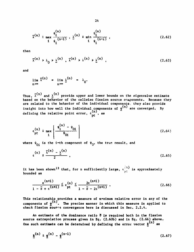
lim (n) - lir a(n)a 0n+n0
Thus, a(n) and 7(n) provide upper and lower bounds on the eigenvalue estimatebased on the behavior of the cellwise fission source components. Because theyare related to the behavior of the individual components, they also provide
insight into how well the individual components of *(n) are converged. By
defining the relative point error, e (, aspt
(n)_
e (n) max(2.64)pt 01
where *01 is the i-th component of %0, the true result, and
(n (n) _ (n)
c = 2 , (2.65)
it has been shown13 that, for n sufficiently large, t: is approximately
bounded as
(n+l) E(n)< 2.n+l(2.66)
1 - o + e(n+l) pt 1- - 2 e (n+l)
This relationship provides a measure of maximum relative error in any of the
components of . The precise manner in which this measure is applied tocheck fission source convergence here is discussed in Sec. 2.2.4.
An estimate of the dominance ratio a is required both in the fissionsource extrapolation process -given in Eq. (2.60b) and in Eq. (2.66) above.
One such estimate can be determined by defining the error vector R as
(2.67)R(n) _ (n) _ (-)
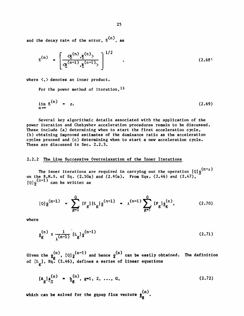
25
and the decay rate of the error, E n), as
<(n),R(n) >
(nl) R(n-1)
J 1/2(2.683
where <,> denotes an inner product.
For the power method of iteration, 1 3
lim E(n) = 0.n+
(2.69)
Several key algorithmic details associated with the application of thepower iteration and Chebyshev acceleration procedures remain to be discussed.These include (a) determining when to start the first acceleration cycle,(b) obtaining improved estimates of the dominance ratio as the accelerationcycles proceed and (c) determining when to start a new acceleration cycle.These are discussed in Sec. 2.2.3.
2.2.2 The Line Successive Overrelaxation of the Inner Iterations
The inner iterations are required inon the R.H.S. of Eq. (2.50a) and (2.60a).
[QJ (n-1) can be written as
[Q (n-)G
[F J[L j(n-1)Fg l g1
carrying out the operation [Q]J(n-1)
From Eqs. (2.46) and (2.47),
G(n-1) F tg (n)
S'-.
(2.70)
f(n) 1 [L 12(n-1)g -(n-1) g
Given the (n), [QJ '(n1) and hence (n)can be easily obtained.of [L ], Eq. (2.46), defines a series of linear equations
[A n)g -g
S (n), g-1, 2, ... ,G,
The definition
(2.72)
which can be solved for the group flux vectors gn.
where
(2.71)

26
The source b is given by (see Eq. (2.112b) for the upscatter problem)-g
b(n) (n)[ + g (n-1). (2.73)-gaggrg (n-1)g
-g g'<g
For multidimensional problems, the direct inversion of [A ] matrices in
Eq. (2.72) is not practical. The iterative inversion of [A ] for each group
comprise the inner iterations.
Because of its sound theoretical basis and computational simplicity (seeSec. x.2.4), the line successive overrelaxation method has been chosen for thesolution strategy reported here. The matrix [A] in Eq. (2.72) (dropping thegroup subscript) is split as2 7
[A] = [D] - [E] - [F], (2.74)
where [D] contains the diagonal of [A ] plus those off-diagonal coefficientsg
which represent coupling between cell fluxes in each row, [E] contains thoseblocks of [A] which lie below the diagonal blocks placed in [D], and [F]contains those blocks which lie above the blocks in [D]. The line successiveoverrelaxation procedure is then given by
I(m+l) () + k , (2.75)g C g -g
where
[L =] ([D] - w[E])- (w[I] + (1-w)[DJ) (2.76)
and
k - ([D] - w[E])-lw b . (2.77)-g -g
The matrix [LW] is the line successive overrelaxation iteration matrix and w
is the overrelaxation factor; both are group-dependent. Because [A] (for eachgroup) is an irreducible consistently-ordered 2-cyclic Stieltjes matrix forthe finite differencing schemes used here, the iteration procedure given byEq. (2.75) is convergent. for 14w2.29 Furthermore, there is an optimum valueof w, say cb, for which the convergence is the most rapid. This group-
dependent value of wb is given by2 7
b 2 (2.78)b 1 + [1 - p([L1 ])J
where p([L1 ]) is the spectral radius of [L1 ], the associated Gauss-Seidel
iteration matrix, which can be obtained from Eq. (2.76) by setting w-l.

27
Following the procedure outlined in Ref. 30, the value of Wb can bedetermined to arbitrary accuracy because the [A] matrix for each group has the
properties listed above. For such matrices, if x(0)>0 and if
x(m) E [L 1 x(m-1) (2.79a)
and
<x/mx m>
6(m) - -<X (m) (m-1)>(x ,x
(2.79b)
then
lim 6(m) = p([LD.m+
Furthermore, if x(ml) 0 and if' i
-(m)x(M)"i
max m) ,i x
a(m)x(m)
minun xm-1) ,
ix
(2.80)
(2.81)
then
and
lim a(m)M+=
- lim 6(m)mm
p([L ). (2.82)
The spectral radius p([L1J) can be computed by carrying out the iteration given
by Eq. (2.79a), computing 6(m), 6(m) and 6 m, and monitoring their convergence
to one another. The computational details involved by implementing thisprocedure for computing 1b are discussed in :ec. 2.2.4.
b(m) > P [L 1]) > d(m)
d(m) > 6(m) > d (m)
=

28
2.2.3 Outer Iteration Computational Considerations
The obvious ultimate goal of the outer iteration procedure is to be ableto apply the Chebyshev acceleration procedure given in Eqs. (2.60) withaccurate estimates of both A0 and a. However, since neither A0 and a are known
when the outer iterations are commenced, a "boot-strap" process is required.As reported in Refs. 12 and 13, it has been found advantageous to perform alimited number of power iterations, Eq. (2.50),_initially to provide a reason-
able estimate of A0 and an initial estimate of a, which is generally quite low.
A series of low-order extrapolation cycles are then utilized, during which the
higher overtones are rapidly damped out and more accurate estimates of a areobtained. Only when all but the first overtone mode are essentially damped
out are high-order cycles based on accurate estimates of a utilized.
The precise algorithm can be described in terms of four basic parts as
follows: 13
1. A minimum of three power iterations using Eq. (2.50) are performedinitially. The first Chebyshev acceleration cycle is begun on outeriteration n*+l, where n*+1 is the smallest integer such that n*>3 for
which the dominance ratio estimate, a satisfied the criterion
0.4 a C 1.0,
where Eq. (2.68) is used to estimate a. That is,
a E (n*). (2.83)
2. Using a as the dominance ratio estimate for a in Eq. (2.61), theaccelerated iterative sequence given by Eq. (2.60) is carried out foriterations n*+p, p>1. At first, low degree polynomials are appliedrepeatedly, with the estimates of the dominance ratio being updatedcontinuously according to
a' - jcosh [ h- ] + 1 , (2.84)
where
YI-Cp 2 -2 )E ,(2.85)
I (n*+p) _(n*+p-l) 2
En*,p-1=(n*+1) _- (n*) (2.86)
II X
-I 2

29
and C _1 is the Chebyshev polynomial of degree p-1. The polynomials are
at least of degree 3 and are terminated when the error reduction factor
En*,p-1 is greater than the theoretical error reduction factor:
E n*,p-l > C p a-. (2.87)
The theoretical error reduction factor is the error reduction which wouldhave been achieved if a were equal to 3, the true dominance ratio. IfEn*,-1 is greater than this, the acceleration cycle has not been as
effective as it should have been, so a new cycle is started using theupdated dominance ratio estimate, a', from Eq. (2.84).
It has been foundjudicious to limit the rate of growth of the dominanceratio estimates, a', during the early stages of the iterative process.Denoting the dominance ratio estimate to be used to start a new polynomialcycle (p-l) at iteration n*+l as a, a is constrained as
min (a', 0.9) , n*+l < 6
A min (a', 0.95) , n*+l < 9a = (2.88)
min (a', 0.985), n*+l < 12
min (a', 0.99) , n*+l > 12
Though seldom needed in fast reactor problems, these constraints helpsmooth the convergence process in problems characterized by largedominance ratios.
3. After the estimates for Q have converged, higher degree polynomials a-e
applied. In fact, the process described in part 2 above is applied
continuously. The length of the cycles increases naturally due to the
improving estimates of U.
4. The outer iterations are terminated at outer iteration n if the followingthree criteria are met:
C (n) < e', (2.89)
I (n) -_ (n-1) I2-2 (2.90)
k(n) (n-1)I1/2
kn - k n-1) k ,(2.91)

30
where e,, e and Ek are input parameters. The test specified in Eq. (2.89)
is a measure of the pointwise eigenvector convergence and is based on thebounds placed on the relative point error in the relationship (2.66). In
(n)computing en, only cells in which the fission source has some minimum(user-specified) relative size are considered. The test (2.90) is ameasure of the average rate of convergence of the eigenvector (the fissionsource), while test (2.91) is a measure of the eigenvalue convergence.The k estimate at the end of n iterations is taken from
(n) (n) 1/2
k(n) =k(n-1) (2.92)eff eff (n) ~(n-1)
Experience has shown that if e and e are assigned equal values, the test
(2.89) almost always controls convergence. The same tests (2.89)-(2.91)are applied after each outer iteration is completed, regardless of whetherthe iteration just completed was a power iteration or an acceleratediteration.
2.2.4 Inner Iteration Computational Considerations
Computational considerations arise concerning three aspects of theinner iterations. These are the computation of the optimum overrelaxationfactor wb for each group, the determination of the number of inner itera-
tions which should be carried out for a given group at a particular outeriteration and the actual procedure used to solve the tridiagonal matrixequations which characterize the line successive overrelaxation method.
It has been shown in Sec. 2.2.2 that the optimum overrelaxation factorfor a given group can be computed if the spectral radius of the. line Gauss-Seidel matrix, p([L1 ]), is known. The procedure outlined in Eqs. (2.79)-
(2.81) provides a rigorous method for determining p([L1 ]). With the coding to
carry out the inner iterations using the line successive overrelaxation methodalready in place, the implementation of this procedure is trivial, since [L1]is equal to [L ] with w set to unity. The vector k in Eq. (2.75) also has
to be set to the null factor.
In order to insure that the actual outer and inner iterations are asefficient as possible, this computation of the overrelaxation factors is doneprior to commencing the first outer iteration. Starting with an arbitrary
non-negative initial guess x , the iteration in Eq. (2.79a) is carried out
for m - 1 to 10. Following each iteration for m > 10, the quantities 6( ,
6(m) and 6(m) are computed. The related quantities w(m), (m) and w ,
defined by12

31
(m) 2
1 + (1 -()1/2
-(m) 2-(m)11/2,
C 1
(2.93)
and
(t) =2
1 + (1 - am))1/2 '
are also computed. The iterations for a given group are terminated when either
(2.94)-(m) m 2 - )
or m = M, where M is a user controlled iteration limit; Wb for that group is
set to w(m). The test given by Eq. (2.94) forces tighter convergence as P([L J)
increases. The amount of CPU time required to precompute the wb is typicallyon the order of one or two outer iterations.
The theory presented in Sec. 2.2.1 on the Chebyshev acceleration methodimplicitly assumes that the matrix equation for each group, Eq. (2.72), issolved exactly during each outer iteration. For multidimensional problems,this is not the case. It has been shown1 3 that the effect of solving Eq. (2.72)iteratively to less than infinite precision for each group is to modify some-what the system of equations being solved. Although both systems share thesame fundamental eigenvalue and eigenvector, the dominance ratio of themodified system is larger than the original system, Eq. (2.48). Some of theeigenvalues of the modified system may be negative or complex, which wouldslow convergence of the outer iterations.
The most practical solution to this problem is to do a sufficient numberof inner iterations for each group during each outer iteration so that theeffect on the dominance ratio is not appreciable, yet no more than this. Ithas been determined experimentally for a range of typical fast reactorproblems1 1 that this can be achieved most economically by doing a fixed numberof iterations, m , for each group during each of the outer iterations. This
eliminates the need for any convergence checking during the inner iterationsand thus eliminates the costly divides which would have to be done to determinerelative convergence on a component-by-component basis.
This number mg is determined for each group by requiring that the normof the continued product of the iteration matrices for that group during eachouter iteration be less than some desired (user controllable) error reductionfactor. This assures that the norm of any of the components of the errorvector is greater than or equal to this error reduction factor during each

32
outer iteration. For a variant of the line successive overrelaxation methodof Eq. (2.75), where a single Gauss-Seidel iteration precedes (m-1) successiveoverrelaxation iterations, the norm of the continued product of the iterationmatrices is given by2 6
[Lm-1][L ]2 [t2- + t ]/2, m > 1, (2.95)Wb ] 122ml1 2w~
where
tm [ _ l-(m-1)/ 2.[P(L 1)Jl/2 [1 +.(m - 1)(1 - [p(L1 )]1/
2)]. (2.95b)
The single Gauss-Seidel iteration is applied because the norm in Eq. (2.95a) isthen strictly decreasing for m > 1. Letting Lin be the desired error reduction
factor and given eb and p(L1 ) for a group from the optimum overrelaxation
factor calculation just described, Eq. (2.96) is solved to determine that valueof m such that
I[LI-l[LlII 4in. (2.96)
The value of m so obtained is the fixed number of inner iterations, mg, that
are done for group g for every outer iteration. There is no direct user controlover m ; it is always computed from Lin.
Experience has shown that choosing Sin < 0.04 will result in no adverse
impact on the outer iteration convergence rate for typical fast reactorproblems. For problems with dominance ratios larger than 0.85 (large reactors),a value of Lin as small as 0.01 is sometimes necessary. It is quite obvious
when a value of ein which is too large for the problem at hand has been chosen.
The dominance ratio estimates being obtained from the outer iteration grow too
large, and oscillatory behavior of the acceleration cycles generally results.
A great percentage of the total CPU time required to solve large problemswith this solution method is spent in the inner iterations. In implementingthe algorithms used to carry out these iterations, it is essential that thefull capabilities of the large-scale scalar scientific computers for whichDIF3D was designed be utilized. A feature shared by some of these computersis the high speed instruction stack, from which significant gains in executionspeed can be obtained when repetitive instruction sequences can be contained inthis stack. Multiple functional units and instruction segmentation permitparallel execution of several arithmetic operations, loop indexing and thestoring and fetching of data.
The requirements for utilizing these features efficiently include thefollowing: (a) compact coding for loops, (b) no conditional branchingperformed within the loop, and (c) avoiding divisions whenever possible. Theone-line successive overrelaxation method was chosen in part because it issimple and can be coded compactly. Performing a fixed number of inneriterations for each group eliminates the need for the divides and conditionalbranching which usually accompanies convergence checking. Finally, by utilizing

33
the procedure outlined below, it is possible to eliminate all divides andconditional branching from the innermost loops of the inner iterationalgorithm and reduce those loops to a few lines of machine language codingwhich easily fit within the instruction stack on, say, an IBM 370/195 or aCDC 7600.
For a particular line of fluxes which are computed simultaneously duringeach inner iteration, the equations which must be solved are of the form
[AkJ(m+1 ) - -jk, (2.97)
(j+1) b(+ ) _ (m)) + ~) , (2.98)jkjk1jjkk+
-jk j kjk + [A k - + jA+lk j+lk +[Ak k-+1 [jk+l jk+l 2.9
where j and k are the row and plane indices of this line, [Ak] are the
matrices given by Eqs. (2.37)-(2.39) and the flux values *0k and J+1k'k-1,2,...,K, and IjO and jK+1, j-1,2,...,J are null. The solution of
Eq. (2.97) utilizes a variant of Gaussian elimination to perform the LU
factorization of the tridiagonal matrix [A kJ.
The forward elimination on the matrices [A k] is performed only once,
prior to the beginning of the outer iterations, in such a fashion as to elimi-nate the need for further divides in computing the tjk. The backward sweep
and overrelaxation are then combined in a single loop to save memory fetchesand stores.
We define E=a in Eq. (2.37) then the forward elimination on [AikI is
d - ,(2.100a)1
ui - d (2.100b)
d -12, 3, ... , I.
d i b - u (2.100c)i iu
The d values are saved for subsequent use in the inner iterations by storing
over the b values, which are no longer needed. Given sjk for one inner
iteration, the forward sweep on it is given by
y - (2'8d1,a(2.101a)
34
(2.101b)- Si + iyi_)di, i - 2,3, ... , I,
where s is the i-th component of sjk. A second loop then performs the
remainder of the work on line j,k according to
x - yi, im+1)
Xi Yi + x i+ld xi
- (n*i +W
, M) + Wb(XI m))
C+l
i- I-i, ... , 2, 1.
S- *m) )
(2.102a)
(2.102b)
(2.102c)
This procedure permits very efficient use of the arithmetic capabilities ofhigh speed scalar computers.
When periodic boundary conditions (e.g. next-adjacent-face periodicity oropposite-face periodicity) are present, the solution procedures given byEqs. (2.97)-(2.102) require modification. The changes are minimized bypermitting periodicity with respect to the domain boundary coincident withcoordinate x , only. Consequently, next-adjacent-face periodicity couples the
x and y1 faces; opposite-face periodicity couples the x and x1 faces. The
changes are summarized for two cases.
Case 1: Next-adjacent-face Periodicity
The following modifications are required:
(1) Replace diagonal element b1 in [Az] (see Eq. (2.37) by
b* - b -a -ay. (2.103)
The elements of [An] are unchanged for j > 1.
(2) Replace transverse leakage terms e = ijk in ask (Eq. (2.101)) by
8 ijk
{ (in)a lkik
sijk + 0
(jkmjl
j-1, i-2,3, .. , I
j"1, i11 (2.104)
J>1, i-l.
(m+1)
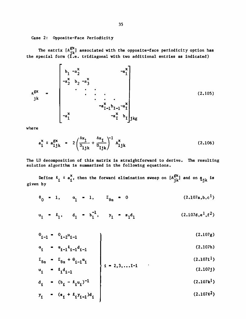
35
Case 2: Opposite-Face Periodicity
The matrix [A k] associated with the opposite-face periodicity option has
the special form (i.e. tridiagonal with two additional entries as indicated)
bl
x-a 2
-a
b2 -a3
-a
- 2/1D1jk
X-a1
-a1 _1b -aI1I-1 I
-a bIJ
k AX+ D I k / uk
(2.105)
j kg
(2.106)
The LU decomposition of this matrix is straightforward to derive.solution algorithm is summarized in the following equations.
Define i=ai, then the forward
given by
60 -1, 1 1, a
l - , d - b ,1 1' d1 1'
i-l 01-2u i-
ai = ai-1 tidi-
Ga - a _ i0_-li
u - Lidiu
d -=(b 1 - A 1
yi - (Si + Liyiu)di
The resulting
elimination sweep on [A ] and ons jkis
- 0 (2.107a,b,c')
(2.107d,e',f 2 )yl - ssd 1
(2.107g)
(2.107h)
(2.1071 1 )
(2.107j)
(2.107k1 )
(2.10782)
Aj
jk
where
Xa1 gx=ali
0 0
-
i " 2,3,...I-1

36
* 36I =RI + 0I-2u _ (2.107m)
u - ( +j u1 1 )d1_1 (2.107n)
di=- (b1 - u - )-1(2.10701)
I-2
71-=(s + L*y 1 + 0eiyi)di (2.107p2 )
i=1
Equations (2.107) may be arranged into two overlapping subsets so that thediagonal terms arising from the LU decomposition may be preinverted prior tothe start of the outer iterations. Equations (2.107) with superscripts 1 or 2apply to the preinversion step or the forward elimination of sjk, respectively.The non-superscripted Eqs. (2.107) apply to both steps.
The back substitution to complete the work on line j,k proceeds accordingto
a 0, 9 XI YI (m+l) (m) +Wb(xI- I )(2.108a)
x- yi + Ri+1 dixi+1 + ai+1xI (2.108b)
i - I-1,...,2,l.
(m+l) - im) + -bi inm)) (2.108c)
The matrices [Ajk] obtained for triangular geometry options with non-
periodic and periodic (next-adjacent-face periodicity only) boundary conditionsare nearly identical to those obtained in the orthogonal geometry case. Conse-quently, the same general solution algorithms and data structures are applied.
Two aspects in which triangular geometry problems differ from orthogonalgeometry problems lead to the two modifications detailed below.
First, because realistic reactor core models do not fully encompass either
the rectangular or parallelogram problem domains required in the triangulargeometry option, provision is made for the specification of background(unoccupied) mesh cells. Computational and physical considerations lead tothe stipulation that the projection of the region of solution of the K planesbe identical. Therefore, the majority of the background cells may be excluded
from the calculation if iterations over line jk are over cells i - 18, s+1,
... ,Ie where I and Ii are the first and last "active" mesh cells on a line.
Occasionally, the reactor outer boundary is so irregular that one or more
background mesh cells appear within the active mesh limits < i < Ie of a
line. The leakage coefficients aik and the initial flux guess *ijk are set
to zero in such a mesh cell, there y permitting computations to proceeduninterrupted for the entire active mesh line.
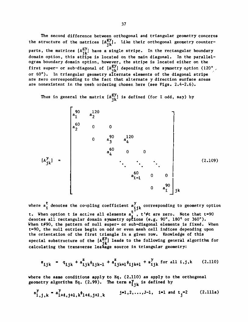
37
The second difference between orthogonal and triangular geometry concerns
the structure of the matrices [AY]. Like their orthogonal geometry counter-
parts, the matrices [Ak] have a single stripe. In the rectangular boundary
domain option, this stripe is located on the main diagonal. In the parallel-ogram boundary domain option, however, the stripe is located either on the
first super- or sub-diagonal of [Agk] depending on the symmetry option (1200
or 600). In triangular geometry alternate elements of the diagonal stripeare zero corresponding to the fact that alternate y direction surface areasare nonexistent in the mesh ordering chosen here (see Figs. 2.4-2.6).
Thus in general the matrix [A ] is defined (for I odd, say) by
90 120a a2
a60 0 0
90 1200 3
a60 0 0
[AY k * * . 2.109)
a6 0 0
900 aI jk
where a denotes the co'ipling coefficient aiyk corresponding to geometry option
t. When option t is active all elements a , t'#t are zero. Note that t90denotes all rectangular domain symmetry options (e.g. 90*, 1801 or 3600).When t#90, the pattern of null super- or sub-diagonal elements ,is fixed. Whent-90, the null entries begin on odd or even mesh cell indices depending uponthe orientation of the first triangle in a given row. Knowledge of this
special substructure of the [A Y] leads to the following general algorithm for
calculating the transverse league source in triangular geometry:
sijk ijk + aijk ijk-1 + azijk+l1ijk+l + s jk for all i,j,k (2.110)
where the same conditions apply to Eq. (2.110) as apply to the orthogonalgeometry algorithm Eq. (2.99). The term aijk is defined by
s5 - a ,k j-1,2,...,J-1, i-l and t -2 (2.llla)

38
s = a *i,j,k i,j,k i-R,j-1,k
= 0i,j,k.
j =2, 3, ... ,J
J2,3,...,J, iie, m =2
otherwise ,
I (2.111b)
(2.111c)
(2.llld)
(2.llle)
where
t - '2:
lmod(i+NTHPT,2)+1:
m = mod (I - t - 1, 2)
(0:
+1 :.
parallelogram boundary domain (600 symmetry)parallelogram boundary domain (1200 symmetry)rectangular boundary domain (NTHPT*=l or 2)
rectangular boundary domainparallelogram boundary domain (600 symmetry)parallelogram boundary domain (1200 symmetry).
2.2.5 Data Management Considerations
Strong consideration must be given to data management implications ofany solution method that is contemplated for use in a code capable of treatingproblems where the number of space-energy unknowns can exceed 106. From theprevious sections, it is obvious that such considerations have influenced theform of the solution method presented here. These considerations aresummarized in this section.
The prime goal of the solution strategy described here is to reduce thenumber of outer iterations to a minimum, even at the expense of investingrelatively greater effort in the inner iterations performed during each outeriteration. By minimizing the number of outer iterations, the number ofscattering source calculations (one per group per outer iteration) is kept ata minimum. These scattering source calculations necessitate the transfer oflarge amounts of data from peripheral storage to core memory for problemsutilizing 10 or more energy groups, yet there is little arithmetic to be donewhile these data transfers are taking place. As a result, CPU utilization canbe quite low during the scattering source calculations, even if efficientasynchronous data transfer methods are utilized.
Data management considerations also led to the decision to apply theChebyshev polynomial acceleration technique to the fission source vectorrather than the flux vector 0. Three complete fission source or flux vectors,
*NTHPT denotes the orientation of the (1,1,1) triangle in the region ofsolution, see the GEODST file description in Appendix C.2.
i +1, j, k -i+1+R , j+1, k i+1+L , j+1, k 12..J

39
depending on which are to be accelerated, have to be stored on peripheralstorage devices and transferred to memory to carry out the accelerationprocedure for each outer. Again, there is little arithmetic associated withthis acceleration method, so that CPU utilization can again be low if largeamounts of data have to be transferred. Since the fission source vectors areonly (1/G) as long as the flux vectors, a significant reduction in datatransfer requirements is achieved by accelerating the I vector.
Because fast reactor models are generally characterized by significantlyfewer space mesh cells than thermal reactor models for reactors of the samethermal rating, relatively less effort is required to carry out the inneriterations for a given group in a typical fast reactor calculation. It isonly for relatively large three-dimensional problems that all of the datarequired for the inner iterations for one group cannot be contained in thememory of the large scale computers available today. The spectral radii ofthe inner iteration matrices for the groups in a typical heterogeneous fastreactor problem are generally lower than those that arise from typical thermalreactor problems. Thus fewer iterations are required to achieve a given amountof error reduction in typical fast reactor problems. This lessens the pricepaid for demanding tighter convergence of the inner iterations in order tominimize the number of outer iterations.
Many relatively large three-dimensional problems that cannot be corecontained may be solved with no appreciable increase in data transfer cost byemploying the concurrent inner iteration strategy. Instead of calculating
(k serially for all lines j,k, this strategy serially computes (i+l) for'jk k( 2 )
the block of mesh planes currently core-contained, then computes (. ) ,jk '
(m+Bmjk there B is the "active bandwidth" of core-contained mesh plans. If
B > mg, the number of inner iterations in group g, then the inner iterationsrequire a single I/O pass comparable in cost to the one group core-containedoption, but usually at a significantly reduced memory size requirement.Details of the concurrent inner iteration strategy are found in Section 4.3.2.2.
2.2.6 Adjhint Solution Strategy
The adjoint problem is solved using the same solution algorithm as thereal problem. The self-adjoint property of the continuous and discretizedwithin-group leakage-plus-removal operator only requires a transformation ofdata in order to utilize the iteration methods just discussed.
The transformation consists of:
(1) Reversing the order of the group structure of the principal
macroscopic cross section data (e.g. E + EG+1-g
(2) Transposing the scattering matrix (i.e.Tgg, + Tgg) and then revers-
ing the order of the group structure (i.e. T , + TG+1-,G+l-g')'The corresponding arrays indicating the up and down (in scatterbandwidth are converted to the corresponding up and down (out)scatterbandwidths.

40
f(3) Interchanging vE g, and Xg terms in the fission source calculation.
The resulting flux eigenvector is then obtained in reverse group order,g=G,G-1,...,1 and the fundamental eigenvalue is identical to the real problemdue to the self-adjoint property of [Q] in Eq. (2,48). Likewise the symmetricwithin group matrices have identical spectral radii p([L ]), hence the wgare identical. Wg
2.2.7 Upscatter Iteration Strategy
DIF3D provides an upscatter iteration for application to problems in which[T ,]>0 for g'>g in Eq. (2.29). The essence of this strategy is to perform (in
each outer iteration) U-1 additional group (inner) iterations for those groups
within the upscatter bandwidth. Let G denote the group index of the firstenergy group that receives a nonzero upscattering source. Then the inner
iterations for the groups without upscatter, g=l,2,...,G-l, follow Eq. (2.72)and Eq. (2.73). The group g inner iteration at outer iteration n and upscatteriteration u is
[A ](n,u) = b(n,u), g = G, C + 1, ... , G (2.112a)g g -g
where
b(n,u) =_ E [T ](n u) + [Tg,](nfu-1) + (11 X (n-1) (2.112b)-g g'g gg g g>gXg g (n-1) g
(no) = (n-1,U) (2.112c)g g
The calculation for the group contributions to the fission source n) resumein the last upscatter iteration pass, U.
The cost of performing U upscatter iterations is approximately equivalent
to solving a problem with (U-1)*(G-G+l) additional groups. If a scattering
band B of fluxes is core contained and if (G-G+1)<B, then the upscatter itera-tions requires no additional I/O transfers for the flux data. Finite differencecoefficients and cross section data transfers will still be required.
Experience with several Safety Test Facility configurations with thermaland epithermal drivers indicates that user-supplied U values between 5 and 10are comparable in performance for the thermal case. U-1 is sufficient forthe epithermal case.
The procedure in Eqs. (2.112) is reversed for adjoint calculations with
upscatter. The upscatter iterations are performed in groups g-G,G-1,...G.
Then the remaining groups, g-G-1,G-2,...,1 are calculated.

41
2.2.8 The Inhomogeneous Problem
The matrix equations describing the fixed distributed source problem maybe written in the form
([M] - p[B]) = s (2.113)
where [M] and [B] are defined by Eqs. (2.35) and (2.42), and S is the externalsource vector. The constant p is specified to ensure the subcriticality ofthe reactor in the absence of an external source. An exception occurs, forexample, in generalized perturbation theory adjoint calculations where thereactor is critical, but the adjoint source S is orthogonal to the fundamentalmode; in this case a solution is guaranteed by the alternative theorem.3 1 Forthis discussion p=1 suffices, since [B] may be redefined. The flux I is subjectto the boundary and interface conditions of Eqs. (2.3)-(2.5).
Equation (2.113) may be written as
= ([I] - [M]-1[B])-lu (2.114)
-lwhere u = [M] S. The properties of [M] and [B] discussed in Section 2.2.1
together with the assumption of reactor subcriticality requires p([M]-1[B])<l.
Therefore, ([Il-EM]-1[B])-1 exists which in turn implies that ([M]-[B])-1 =
([I]-[M]-1[B])-1 exists. Because [M] is nonsingular, the iterative process
[M]gn = [BJ n-1 + S (2.115)
for the flux i generated from the regular splitting18 ,3 2 of ([M]--[B]) willconverge.
The flux iteration is reduced to a fission source iteration by followingthe procedure outlined for the eigenvalue problem, provided the definition of
is appropriately modified for the fixed source problem, i.e.
-- g
= [Lg+[AJ ( Y [T ,]S , + S ). (2.116)g g g ~ . gg-g -g
g'#g
Then multiplying Eq. (2.113) by [F] and using Eqs. (2.42) and (2.44) we obtainthe reduced problem
i = ([I]-[Q])lv, (2.117)
Twhere v = [F] u and [Q] is defined by Eq. (2.49). Because the nonzero eigen-
values of [0] and [M]-1[B] are identical, p([Q])(l and therefore ([I]-[Q]) 1
exists. Consequently, the iterative process

42
= Q]*n-1 + v (2.118)
generated from a regular splitting of ([I]-[Q]) will converge and the fissionsource vectors obtained from the flux problem and the fission source problemwill be identical.
The rate of convergence in fixed source problems is dependent on p([Q]).The Chebyshev acceleration method detailed in Section 2.2.1 can therefore beapplied to the iterations in Eq. (2.118) provided that suitable estimates ofp(0) are obtained. One such estimate may be obtained using Eq. (2.68), whichfor the fixed source problem is easily shown to satisfy the relation
(n)lim E = p([Q]). (2.119)
n-m
The previously describeP' Chebyshev acceleration procedures may be used directly
in fixed source problems, provided we redefine the meaning of the symbol a tomean p([Q]), the spectral radius of the iteration matrix.
The inner iteration process in fixed source problems differs from itscounterpart in eigenvalue problems only by the presence of an additional sourceterm contribution to gjk in Eq. (2.99).
When the fixed source problem is near-critical (i.e. p([Q]) approachesunity), convergence rates, even with Chebyshev acceleration are unacceptablyslow. Application of a single asymptotic extrapolation3 3 ,34 prior to thefirst Chebyshev acceleration significantly reduces the required number ofiterations. This reduction is achieved by an approximation procedure thatattempts to correctly scale the contribution of the fundamental eigenvectorto the flux solution. This approach is motivated by the fact that in near-critical source problems the fundamental eigenvector term dominates the solu-tion.
If we assume, therefore, that the n-th iterate of Eq. (2.118) convergesto the exact solution r' with asymptotic behavior
*0= ,(n) + pn([Q])c 0. (2.120)
where c1 0 is an arbitrary multiple of the fundamental eigenvector of [Q]corresponding to p([Q]), then it follows that an improved n-th iterate is
N(n) (n) (n) (n) _ (n-1)) (2.121)
where the extrapolation factor t(n) is defined by
43
(n)
=)(n). (2.122)1-p
Here, p(n) = E(n) is the estimate for p([Q]) at the n-th unaccelerated poweriteration.
As alluded to earlier, the effect of the extrapolation is to rescale the
contribution of the fundamental vector to the solution. The extrapolationfactor also increases the magnitude of the higher harmonics. However, these
are readily attenuated by the Chebyshev acceleration procedures that (after asingle unaccelerated outer iteration) are applied to subsequent iterations.
To ensure that an asymptotic behavior has been achieved, the single
extrapolation is performed when the following conditions are met:
1. (n) < .1 (2.123a)p
2. s(nl )< .1 (2.123b)p
3. n > 5 (2.123c)
where
(n) (n-l)) T(n) (2.123d)
T
The asymptotic extrapolation procedure typically leads to a factor of 2 ormore reduction in the number of outer iterations required to achieve compar-
able fission source accuracy with the standard acceleration method.
2.3 The Criticality Search Option
2.3.1 Statement of the Problem
The criticality search17 seeks to achieve a desired reactor k-effective,
kd, by adjusting certain parametric vectors which are constrained to lie
along a given straight line. The parametric vectors considered here aresubzone volume fractions which are discussed later in section 2.3.3. Othercommonly used parametric vectors (not implemented in DIF3D) include buckling,dimension and reactor period (a).
If p = (p1,p2''''' R) denotes a parametric vector, then the desired
vector is constrained to lie on the line given by
P(s) = p + s.62 (2.124)
44
where 6 = (6pl,6p2'''' R) denotes the parametric modifiers (the direction
cosines for the line), and p denotes the initialized state of the parametervector when s=0.
For reasonable* values of s and 6, the parametric vector 2(s) generates
matrices [M(s)] and [B(s)] having the same general properties as the matrices[M] and [B] in Eq. (2.34). Then associated with each vector 2(s) is k =k(s),
the solution to the eigenvalue problem
[M(s)] k - [B(s)] . (2.125)
The object of any search then is to solve the equation
k(s) = kd. (2.126)
2.3.2 Method of Solution
The solution of Eq. (2.126) is achieved by repeatedly solving Eq. (2.125)for a series of carefully selected estimates sn* This iterative process hasthree principle steps. The first step estimates sn; Step 2 solves Eq. (2.125)for k(sn) and Step 3 performs the convergence check on k(sn)e
Step 1: Estimation of sn
s and s2 are derived from user data. s3 is determined by linear
interpolation or extrapolation of data from search passes 1 and 2:
sn=- sn-1 + en-1/(dk/ds)n-l (2.127)
where
en = kd-k(sn) (2.128)
(dk/ds)n - (k(sn) - k(sn ))/(sn - sn-1). (2.129)
When n>3, the three most recent estimates {sn-1,sn-2,sn-3) determine a parabola
2p(s1) - p si + p2si + p3 - k(si), i - n-l,n-2,n-3. Then, sn is the root of
p(s)-kd=0 that is closest to sn_1.
*The user is expected to specify an initial configuration [M(0)] and [B(0)]
that is reasonably close to the desired solution, and is expected to specifysearch parameter constraints that avoid non-physical ,nfigurations.

45
If the parabola is degenerate (a straight line) or if the roots ofp(s)-kd=O are complex, then linear extrapolation is applied. The estimatehaving the largest ei and which upon removal leaves two estimates that bracketthe solution kd will then be discarded (This is the regula falsi algoritm35).
If the parabola is not degenerate, a similar root bracketing procedure
is used to discard in favor of sn the least useful estimate among sn-1' sn-2and sn-3'
Step 2: Solution of Eq. (2.125)
The eigenvalue problem Eq. (2.125) is solved using the methods discussedfor Eq. (2.43). The matrices [M(s)] and [B(s)] are defined by
[M(s)] = [M(0)] + X[6M] (2.130a)
[B(s)] = [B(O)] + A[6B] (2.130b)
where [M(0)] and [B(O)] denote the matrices obtained with no contributionsfrom the search ("modifier") subzones and X[6M] and X[6B] denote the matrix ofperturbations resulting from the inclusion of the search modifier subzones.[6M] and [6B] have the same general structure as [M] and [B], but the former
are quite sparse due to the limited number of compositions usually modified
during a search.
Step 3: Termination Tests
Search passes are terminated by any one of the following events:
1. kd - k(s ) < ed where ed is a user-supplied threshold;
2. n = n where n is a user-supplied iteration limit;max max
3. s < sm and s > s where smin and smax are minimum and maximum
limits on the range of s. The first time sn exceeds the search range
say, sn < smin, it is set to smin. A subsequent violation of the
limits cause termination.
4. Insufficient time remains to perform the next eigenvalue calculation.
2.3.3 Comments on the Concentration Search Option
On each search pass the SRCH4C module rewrites the subzone6 volume frac-tions on the CCCC file NDXSRF and the HMG4C module calculates the correspond-
ing macroscopic cross sections for the code-dependent file COMPXS. This ap-proach is attractive for two reasons. First, the creation of "modifier" sub-
zones (i.e. collections of isotopes or materials which are to be varied during
the search) requires minimal effort o: the part of the user. During the search

46
process it is a trivial matter for SRCH4C to rewrite the subzone volume frac-tions on the NDXSRF file. The second advantage of this approach is modularity.Arbitrary neutronics computation modules that use the CCCC interface files may
be employed to solve the eigenvalue problem.
The alternative to subzone volume fraction modification requires atom den-
sity modification for all nuclides in the CCCC file ZNATDN, a job of consider-ably larger magnitude that yields a marginal improvement in user convenience.
The economics of incurring the overhead associated with repeated exits
and reentries to the neutronics module might argue against the modular approach.The net gain from avoiding such overhead was considered marginal compared to
the benefits of modularity.
Except for the prompt fission spectrum cross section type, the modifica-
tion of subzone volume fractions in "modifier" subzones yields the followinghomogenization equation
Emig = ai'nimV + s n axE (2.131)iem o o iEm s
o s
where
Ex'g is the macroscopic cross section of type x for group g in zone m;
a xgis the microscopic cross section of type x for group g for isotope i;
m denotes the set of isotopes in the primary zone assignment and subzone0 assignments of zone m (modifier subzones are excluded);
m denotes the set of isotopes in modifier subzone assignments of zone m;
nim is the atom density of isotope i in the appropriate set m or m;
fV is the zone or subzone volume fraction assigned to isotope i in the set
m=m orm.o s
Equation (2.131) may be viewed from a macroscopic standpoint as
E'g = Exg + s 6Exg (2.132)m m n m
o s
where
Emig = E__ , n1 g V (2.133a)m 0i 0im im
0 iem 0 00

47
and
6E ' = ag n . (2.133b)ss em s
Modification of the prompt fission spectrum cross section depends uponwhich of the three available homogenization options are selected.
Option 1: Use set X vector for all zones
(X,)n = (Xg). (2.134)
Option 2: Use isotope fission vectors with total fission source weighting
(X)nimVim E (vaf)g
(Xi9)n = g -- (2.135)
nimV f (vaf)i
em
fwhere V = s for those isotopes in search modifier subzones.
Option 3: Use isotope fission vectors with (vaf) weighting
(X )nimV (vaf)i
(Xm)n = e(af (2.136)n V (vaf)
There are no restrictions on subzone modifiers or on the zone being modifiedwith regard to fissionable or nonfissionable cross section types or with regardto scattering bandwidths.
2.4 Summary
The mesh-centered finite-difference approximation introduces a three-,five- or seven-stripe symmetric matrix of coupling coefficients that are com-puted using Eqs. (2.25)-(2.27); Tables 2.1 and 2.2 summarize formulas associatedwith each geometry option. The required source term is computed using Eq. (2.28)and Eq. (2.2). During each inner iteration a particular line of fluxes issimultaneously computed by solving Eqs. (2.97)-(2.99).
For a wide class of LMFBR problems no user input is required by theacceleration strategies described in Sections 2.2.1-2.2.4. On option the usermay override ein, the inner iteration error reduction factor in Eq. (2.96),which influences the fixed number of inner iterations to be performed during thewithin-group calculations in each outer iteration. Section 3.15.2 addressesperformance issues in this regard. Performance (i.e. job cost) is also directlyrelated on many host installatiosto the user-specified ECM storage containersize, ultimately the job memory size. Sections 3.9.1 and 3.10.1 address thisissue.
48
3. A GUIDE FOR USER APPLICATIONS
3.1 Setting Up a DIF3D Job - An Overview
As mentioned in the introduction, the code described in this report is,in fact, a collection of quite independent code blocks. DIF3D actually isonly one of these code blocks; the others process input data required bythe diffusion-theory calculation. It is a common, though sometimes confusing,practice to apply the name "DIF3D" to both the complete set of code blocksand the specific diffusion-theory calculation code block.
The DIF3D code block itself reads only binary files. Other code blocksread card input and convert the data to binary files. The input to thecode, therefore, is generally a mix of binary files written by code blocksand card-image files composed by users. Users have a variety of optionsavailable in choosing the mix; their choice then determines which code blocksare actually executed.
This section is a brief overview of the input requirements. Latersections go into greater detail. Information regarding specific input datasets or conventions may be rapidly located by using the table of contents withits detailed subsection headings.
3.1.1 Input Binary Files
In practice the input to DIF3D (the collection of code blocks) usuallyincludes only a few binary files. Unless otherwise noted these files will beone of the CCCC interface files described in Appendices C.1 - C.10.
Microscopic cross section libraries are usually maintained as binaryfiles; DIF3D can use two alternative formats, ISOTXS or the code-dependentfile XS.ISO (see Ref. 36).
For restart and in cases where reasonable flux guesses are availablethe binary flux file RTFLUX may be input. The adjoint flux is stored inthe binary file ATFLUX.
Other input binary files may contain macroscopic cross sections (COMPXS)(see Appendix D.1), atom number densities (NDXSRF,ZNATDN), geometry specifica-tions (GEODST), inhomogeneous sources (FIXSRC), criticality search parameters(SEARCH) and code-dependent data (DIF3D) (see Appendix D.2). Files in thisgroup are rarely input to the code; it is usually simpler to supply data incard-image form.
3.1.2 BCD Card-Image Model Input
When input data are not provided in binary files one or more of theinput processors will be evoked to read BCD card-image files and to writeappropriate binary files. This is done automatically; users do not have toprovide any special instructions.
BCD input is divided into a number of blocks of data called "DATASETs".The general BCD input format for DIF3D is described in a later section of thischapter; the card-by-card input descriptions are included in the AppendicesB.1-B.4.

49
Atom number densities, geometry specifications, inhomogeneous sourcesand criticality search parameters can all be input in the A.NIP3 DATASET (seeAppendix B.4).
Microscopic cross sections can be input in BCD form in A.ISO (seeAppendix B.3), a BCD equivalent of ISOTXS.
Finally, at Argonne any of the CCCC files6 ISOTXS, RTFLUX, ATFLUX,NDXSRF,ZNATDN, GEODST, FIXSRC, and SEARCH can be generated directly from theDATASET A.LASIP by the LASIP3 code37. LASIP3 is a Los Alamos NationalLaboratory input processor.
3.1.3 BCD Card-Image Calculation Parameter Input
Two DATASETs, A.DIF3D and A.HMG4C, contain input parameters for the dif-fusion-theory calculation and the cross section homogenization, respectively.In practice these DATASETs usually contain only a few cards. Nearly all theparameters have defaults which have been set within the coding to valuesappropriate for a wide range of problems.
Among the more important input job parameters are the sizes of the FCM(fast core) and ECM (extended core) data containers. In several places (e.g.A.NIP3, A.DIF3D, A.HMG4C) the user may override defaults and specify the amountof core individual code blocks are to use for data storage. Even on machineswith only one level of memory (e.g. IBM machines) two containers are required.
3.1.4 Edits
Individual code blocks offer a variety of edits, most of which can becontrolled by the user via input flags. Because most code blocks are indepen-dent programs it frequently happens that particular data can be edited fromseveral different places in the code. For example, macroscopic cross sectionscan be edited in the code block that performs the homogenization (HMG4C) or inthe diffusion-theory solution (DIF3D).
Most edits can be routed to one or both of two output media by means ofthe edit flags. The regular print file (logical unit 6 at Argonne) is normallya printer; the auxiliary print file (logical unit 10 at Argonne) may be anydevice the user chooses (e.g. microfiche or a disk file).
3.2 BCD Input Conventions
In the input convention used in DIF3D and most other Applied Physicscodes, the input BCD card images are grouped into "BLOCKs", and the cardimages within each BLOCK are grouped into "DATASETs". BLOCKs and DATASETsare identified by cards containing one of the following phrases:
BLOCK=blknamDATASET=dsnameUNFORM=dsnameNOSORT=dsnameMODIFY-dsnameREMOVE=dsname
The words to the left of the "=" sign are "keywords"; the words to the rightof the "=" sign are unique BLOCK or DATASET names. Keywords must start incolumn 1 of the card, and there can be no imbedded blanks.
50
Both binary and BCD files are given names and, following the CCCC conven-tions,6 version numbers. Binary files include CCCC standard interface files,code dependent interface files for passing data between load modules, andscratch files used only within particular load modules. BCD files for AppliedPhysics codes are usually given names starting with "A."; for example A.NIP3is the BCD file which defines the neutronics input geometry and isotopicnumber density data.
The number of versions permitted for a particular file is established byindividual programs. In references in the BCD card input to one of severalversions of a file, the version number must follow the file name and be sepa-rated from it by a comma. Taking examples from the list of keyword phrasesabove:
DATASET=A.SAMPLE,2REMOVE=RTFLUX,1
A version number of unity is implied when no version number is given. Thus,
the second example above could have been written:
REMOVE=RTFLUX
DIF3D users can normally ignore version numbers; the commonly used files comein only one version. The exceptions are the UDOIT binary files, which areintended for individual applications of DIF3D.
3.2.1 BLOCK=
The BCD input stream is divided into BLOCKs, and each BLOCK starts with acard containing
BLOCK=blknam
In the DIF3D input "blknam" may be either the word "OLD" or the word "STP021".The special case of BLOCK-OLD is discussed in a later section. STPO21, whichstands for "Standard Path 21", is the name given at Argonne to the sequence ofmodules making up a DIF3D calculation. A BLOCK ends at the last card before
the next BLOCK= card or at the end of the card input file, whichever isencountered first.
As far as the user is concerned, the phrase BLOCK-STPO21 causes theexecution of a DIF3D job. If the phrase occurs twice in the input streamDIF3D is executed twice. Only data contained in the first BLOCK are availableto the program during the first execution. Data in the second BLOCK modifyor replace the first BLOCK data for the second execution.
3.2.2 DATASET-, UNFORM=, NOSORT-
The data within each BLOCK are subdivided into DATASETs, and each DATASETstarts with a card containing one of the phrases:
DATASET-dsnameUNFORM-dsnameNOSORT-dsname

51
A DATASET ends at the last card before the next keyword or at the end of thecard input file, whichever comes first. The order of dissimilarly namedDATASETs within a single BLOCK makes no difference to the execution of theprogram.
DATASETs designated DATASET= or UNFORM= are expected to containcards on which the first two columns contain either
1. a positive, 2-digit, nonzero"card type number," or
2. blanks, zeros or non-numeric characters.
The type numbers (01, 02, .... 99) are used to identify the type of data oneach card. For example, in the BCD input file named A.NIP3 mesh data aresupplied on "type 09 cards" (card-images that have "09" punched in columns 1-2).
At the beginning of each job the cards with card type numbers are auto-matically rearranged in order of ascending card type number in DATASETs speci-fied by DATASET= or UNFORM=. When more than one card of a particular cardtype is present the relative order of those similarly numbered cards isunchanged.
At the same time as numbered cards are reordered, unnumbered cards (thosewith blanks, zeros or non-numeric characters in cols. 1-2) are collected andplaced after all numbered cards. Some users use unnumbered cards as "commentcards" to annotate their decks of numbered cards; before the data are read byapplications load modules the unnumbered comment cards are swept to the backof the DATASET where they will not be seen by the load module. A listing ofthe input deck before sorting is printed on the user's output medium so thatthe comments are available for documentation.
DATASETs designated NOSORT= are not reordered in any way. NOSORTDATASETs are normally used for data required by a load module which waswritten at another installation but which was incorporated as a load modulein an Applied Physics production code. In DIF3D A.ISO and A.LASIP are NOSORTDATASETs.
Most DIF3D DATASETs can be input in either formatted or unformattedform. When prefaced by DATASET= the data must all be input in the formatsspecified in the input description for each card type. When prefacedby UNFORM= the data may be in free-format, but subject to the rules outlinedlater in this chapter in the section on free-format syntax. In eithercase cols. 1-2 are still reserved for card type numbers. The format rulesfor NOSORT DATASETs depend on the individual load modules which read them.
When BLOCK-blknam appears twice in the input - specifying two executionsof the same sequence of load modules - DATASETS in the first BLOCK are auto-matically preserved for the second execution unless the user deliberatelyredefines a DATASET in the second BLOCK. For example,
52
BLOCK=STPO21DATASET=A.NIP301 data ...02 .........07 .........
BLOCK=STPO21DATASET=A.NIP301 new data02 .........
06 .........
The first DATASET is entirely replaced by the second before the second execu-tion. A later section discusses how one can make selective changes to DATASETs.
3.2.3 BLOCK=OLD
The special BLOCK "OLD" permits the user to tell DIF3D which files alreadyexist on disk and are being input to the calculation. Input disk files mustbe listed under BLOCK=OLD in the following manner:
BLOCK=OLDDATASET=dsnameDATASET=dsname
etc.
BLOCK=OLD may be placed anywhere in the BCD card input file.
These BLOCK-OLD files are usually binary library or restart files.Occasionally it may be convenient to create and save a BCD file in one job andthen pass it to a second job on disk rather than in the BCD card input file.In such a situation the DATASET name should appear under BLOCK=OLD in thesecond job and not in any other BLOCK processed by the second job.
3.2.4 MODIFY=, REMOVE=, nn=DELETE
MODIFY=dsname permits the user to replace cards of a particular card typein an old DATASET without affecting the rest of the data. Type-numbered cardsfollowing MODIFY-dsname replace the cards of that type (or those types) in apreviously defined DATASET. For example, if a DATASET in one BLOCK containsseven type 09 cards and five new type 09 cards are provided in a second BLOCKunder MODIFY=dsname, then the seven original cards are deleted and the fivenew cards substituted before the second execution.
Some users like to define a reference DATASET with DATASETdsname andthen make changes in the same BLOCK before execution with MODIFY-dsname.
REMOVE-dsname deletes the entire DATASET. This option frequently is usedwith binary files to force applications load modules, for one reason oranother, to rewrite a file.
nn-DELETE, where nn is a card type number, after a MODIFY-dsname willcause all of the type nn cards to be deleted from the DATASET.

53
3.2.5 Sample Input
Figure 3.1 shows a BCD card input file for a fictitious program. Theinput is designed to exercise most of the options described above. Three inputDATASETs are defined; they are two separate versions of a file named A.SAMPLEand one named A.XAMPLE. Below the listing of the input, Figure 3.1 shows thecontents of each file after preprocessing and before the imaginary program isexecuted. There are two BLOCKs (i.e. two executions in the job).
MODIFY= is used in the first BLOCK to modify a DATASET defined in thesame BLOCK (A.SAMPLE,2). It is used in the second BLOCK to modify a DATASETdefined in the first BLOCK (A.SAMPLE,1).
Note that A.SAMPLE,1 and A.SAMPLE,2 are defined with DATASET= and UNFORM=;the cards are reordered according to card type with unnumbered cards placedlast. A.XAMPLE is defined with NOSORT= and is unaffected by the preprocessing.
3.2.6 Output from BCD Input Card Preprocessors
The BCD input preprocessing routines normally produce two kinds of edits.At the beginning of the job the user's input is listed on both the regularand auxiliary output print files by the routine SCAN. In addition, allDATASETs processed under each BLOCK=blknam are edited by the routine STUFF.Users have control over the STUFF edits for each BLOCK through an integersentinel, n, that can be added to the BLOCK= card:
BLOCK=blknam,n
n = 0, edits given on both regular andauxiliary output files (default).
= 1, edits on regular output file only.= 2, edits on auxiliary output file only.= 3, no edits for the current BLOCK.
3.3 General Philosophy on Input Data
A number of principles have guided the design of BCD card input for DIF3Dand other Applied Physics codes.
1. Data that are not essential to the problem should not be required inthe BCD card input. In particular, no redundant data should berequired.
2. Card input files should be easy to create and to modify.
3. Whenever possible, labels and names should be used instead of numbersfor descriptive data.
The BCD input conventions defined in the previous section support these prin-ciples.
The convention of numbered cards containing very specific types of datahelps to eliminate nonessential and redundant data. The preprocessing routinespass to the applications programs the number of cards of each type contained

54
BLOCK=TESTDATASET=A.SAMPLE
A.SAMPLE,1
09 09 CARD05 1ST 05 CARD
5 2ND 05 CARDUNNUMBERED
07 07 CARD5 3RD 05 CARDUNFORM=A.SAMPLE,2XX A.SAMPLEXX VERSION 208 08 CARDMODIFY=A. SAMPLE, 208 REPLACE 08BLOCK=TESTMODIFY=A.SAMPLE ,1
09=DELETE05 REPLACE 05REMOVE=A.SAMPLE,2
NOSORT=A.XAMPLEA.XAMPLENO SORT
07 TYPE 07 CARDNO NUMBER
07 ANOTHER 07
To the left is a sampleinput file illustratingmany of the input processingoptions. There are twoBLOCKs and three DATASETsreferenced.
Contents of each of the three DATASETs after thefirst BLOCK is processed.
A. SAMPLEversion 1
1ST 05 CARD2ND 05 CARD3RD 05 CARD07 CARD09 CARDA.SAMPLE,1
UNNUMBERED
08XXXx
A.SAMPLEversion 2
REPLACE 08A.SAMPLEVERSION 2
A. XAMPLE
not defined inthe first BLOCK
Contents of each of the three DATASETssecond BLOCK is processed.
REPLACE 0507 CARDA.SAMPLE,1
UNNUMBERED
not defined inthe second BLOCK
A.XAMPLENOSORT
07 TYPE 07 CARDNO NUMBER
07 ANOTHER 07
Illustration of Input Conventions
05550709
0507
after the
Fig. 3.1.

55
in a particular DATASET. The user never has to tell a code how many data of aparticular type are input; the code determines this fact independently. Defaultvalues can be provided not only when a particular datum is missing, but alsowhen whole card types are missing.
About forty different card types are defined for the geometry and isotopenumber density file A.NIP3. Rarely are more than a dozen used for a particularjob. Instead of user supplied sentinels, the presence or absence of particularcard types signals options. Explicit sentinels would be redundant.
Numbered cards and the free-format option make it relatively easy tocreate and modify DATASETs. Long strings of input data and tables are conven-ient to the programmer but not to the user. Applied Physics input has alwaystended towards requiring only a few pieces of data per card, with the formatof the card designed for the convenience of the user. In some cases cards ofa particular type may be shuffled without affecting the definition of a problem.In other cases the order of cards within a card type has significance; thedata on one card may overlay, in some way, data defined on a previous card.Modifications to input can frequently be made simply by adding or changingthe order of cards; no changes to existing cards are required.
If nothing else, the use of labels instead of numbers for input quantitiesmakes the BCD card input file readable to users. In the A.NIP3 DATASET, forexample, compositions and geometric regions are given labels, and isotopesare referred to by name.
3.4 Free-Format (FFORM) Syntax Rules
Free-format input is processed by a subroutine named FFORM. The followingset of rules applies to data prepared for UNFORM= DATASETs.
3.4.1 Delimiters
Data (integers, floating point numbers and Hollerith words) must beseparated either by blanks or by combinations of one or more of the fourspecial delimiters:
comma( left parenthesis) right parenthesis/ slash
3.4.2 Data Forms
Integer and real numbers must be written according to the usual FORTRANrules and may not have imbedded blanks. Hollerith data can be supplied in anyof the following three ways:
1. A string of letters and numbers, beginning with a letter, with noimbedded blanks.
e.g. U238 PU239

56
2. A string of symbols surrounded by asterisks or apostrophes. In thecurrent version of FFORM for CDC machines only the asterisk can be usedto set off Hollerith data; the apostrophe has not been implemented.
e.g. *NA 23* 'REG1'
3. A string preceded by the Hollerith prefix nH, where n is an integerconstant.
e.g. 3H016
On'IBM machines an asterisk may be part of a Hollerith string only whenthat string is surrounded by apostrohpes (e.g. 'X*Y') or defined by the nHconvention (e.g. 3HX*Y). Similarly an apostrophe may be a part of a Hollerithstring only when that string is surrounded by asterisks (e.g. *ED'S*) ordefined by the nH convention (e.g. 4HED'S). On CDC machines (where FFORMcurrently does not recognize apostrophes) an asterisk may be part of aHollerith string only when that string is defined by the nH convention.
When a single asterisk (or apostrophe) is encountered the remaining dataon the card are treated as Hollerith data. This does not apply, of course, toan asterisk that is clearly a part of a Hollerith string.
When FFORM passes the data it has read to the calling program, it hasstored Hollerith data six characters to the word. If the input descriptioncalls for one or more separate Hollerith words each word, therefore, must besix characters or less.
3.4.3 Implied Blanks and Zeroes
Pairs of commas, slashes, or left and right parentheses in consecutivecolumns of the card image will be interpreted as integer zeroes. Pairs ofasterisks (or apostrophes) in consecutive columns of the card image implyHollerith blanks.
e.g., , () = // = 0** = '' = 1H
3.4.4 nR, the Repeat Option
nR causes the previous datum to be repeated n-1 times. n is an integer
constant. When several pieces of data are enclosed by slashes or parenthesesand are followed by a repeat instruction, the entire string of data will berepeated. Repeats can be nested by the use of slashes and parentheses, buteach pair of symbols (// or 0) can be used only once per nest. This limitsthe depth of the nest to two levels.
e.g. 1.0,3R/2.0,1/2R = 1.0 1.0 1.0 2.0 1 2.0 1/(WORD 2R) 3R/ 4R = WORD 24R
3.4.5 $, End of Card
All data including and following a $ will be ignored. This will permitthe user to include comments on a card. The symbol $ between asterisks (orapostrophes) or somewhere in an nH field is not affected.

57
3.4.6 UNFORM and Card Type Numbers
Card type numbers must continue to appear in columns 1-2, but all subse-
quent data can be punched without regard to field definitions.
e.g. UNFORM=A.NIP301 title02 0 1 0 7R
etc.
3.5 Microscopic Cross Sections - ISOTXS, XS.ISO and A.ISO
The binary CCCC interface file ISOTXS (see Appendix C.1) is the principalmeans for specifying microscopic cross section data for a DIF3D calculation.Users may alternatively supply either A.ISO, the formatted version of ISOTXS,or (at Argonne only) XS.ISO, the predecessor to ISOTXS at Argonne. Data fromthe alternative files are used to create a temporary ISOTXS file, the ultimateform in which data must be specified for use by DIF3D.
At Argonne, ISOTXS (and XS.ISO) files are generated by MC2-2 (Ref. 38),a code which solves the neutron slowing down problem using basic neutron dataderived from ENDF/B data files.39 When XS.ISO is specified, an ISOTXS file iscreated by the module CSE010 early in the DIF3D Standard Path.
The formatted file, A.ISO, provides a machine independent means forexporting ISOTXS data. It also becomes ar expedient means for creating smallcross section files for a variety of applications. The sample problem inSection 5.5.1 uses an A.ISO data set.
While creating an A.ISO data set special attention must be given to thefact that certain data records require an extra blank card-image. Thisrequirement arises only when the number of data items is such that the portionof a format statement preceding a slash (/) is exhausted, but the portionfollowing the slash is not used.
3.5.1 Reaction Versus Production Based (n,2n) Cross Sections
Users should be aware of at least two things about ISOTXS. First, in theprincipal cross-section record (also called the 5D record), there are slotsfor both transport and total cross sections. Cross-section sets generated byMC2-2 (Ref. 38) contain both, and they are different. Second, there are slotsfor (n,2n) scattering cross sections in both the principal cross-section recordand in the scattering sub-block record (the 7D record). The principal (n,2n)
cross section, an2n,g, is a vector of length equal to the number of energy
groups. It is the probability, per unit group-g flux and per atom, that a
neutron in group g will undergo an (n,2n) scattering reaction; i.e. it is
reaction-based. The (n,2n) cross section in the 7D record, ag(n,2 n), is a
group-to-group transfer matrix (number of groups by number of groups) whichrepresents the probability that a neutron will be produced in group g' as aresult of a scattering event in group g; it is production-based.

58
These definitions are clear in the current, version IV definition ofISOTXS found in Appendix C.1. There are notes at the end of the 4D recordand 5D record that make the distinction and that point out that
0n2n,g _ 1gg(n,2n) (3.1)
g'
Until about seven years ago, however, the file definition made no distinctionbetween reaction-based and production-based cross sections, and there was adifference of interpretation within the FBR community.
Argonne previously used the XS.ISO format, in which elastic, inelasticand (n,2n) scattering cross sections were carried along in separate records.The (n,2n) reaction data was treated as being reaction-based. The practicewas continued by storing reaction-based elastic, inelastic and (n,2n) scat-tering matrices separately in ISOTXS; our ISOTXS files normally do not con-tain a total scattering matrix. Most of the other FBR laboratories were usedto dealing only with the total scattering cross section, and the factor of2.0 (see Eq. (3.1)) required for the (n,2n) production-based matrix had to befactored into the total when the three partial reaction cross sections weresummed. In other words, they were used to dealing with production-basedcross sections. Due to this confusion it became necessary to tighten thedefinition in favor of the production-based interpretation, because a reaction-based, total scattering cross section is useless once the total has beenformed - it is impossible to insert the factor of 2.0 that is needed inwriting the scattering source term in the neutron balance equations. As aconsequence of this inconsistency, HMG4C the code block which processes themicroscopic data (ISOTXS) into macroscopic data (COMPXS) performs a check todetermine whether the (n,2n) scattering matrix (if present) is reaction orproduction based. Hence the proper total scattering source is returned undereither definition.
3.6 Number Densities, Cross Section Homogenization and Edits
The code block HMG4C combines microscopic cross sections (from ISOTXS)and atom number densities (from the CCCC files NDXSRF and ZNATDN) to formmacroscopic cross sections. These macroscopic cross sections are output toa binary file called COMPXS (see Appendix D.1) which is read by DIF3D to obtaincomposition and energy group dependent data. HMG4C will optionally edit theCOMPXS file contents.
3.6.1 Compositions, Zones and Subzones - A.NIP3 13 and 14 Cards
The terms composition and zone are used interchangeably in this reportand in associated documentation. The term composition has traditionally beenused at Argonne to mean a mixture of isotopes and a set of macroscopic crosssections. The term zone was introduced by the CCCC file definitions and isfunctionally equivalent to a composition. The definitions are not preciselythe same, however. In the NDXSRF file there are volumes associated withzones - suggesting an additional, geometrical implication. This impliedrelation is never used by DIF3D. Each composition is simply assigned to oneor more geometric regions of the reactor.
DIF3D provides the user with the means for creating several subcollectionsof isotopes so that the specification of isotopic mixtures may be simplified.This permits a building block approach whereby similar subcollections

59
(materials and/or secondary compositions) may be used in several compositions.The example supplied with the A.NIP3 file description (Appendix B.4)illustrates the flexibility provided by the A.NIP3 type 13 and 14 cards.
Materials can be defined on type 13 cards in terms of isotopes and/or interms of other materials. Two types of compositions may be defined on thetype 14 cards. Secondary compositions are mixtures of materials and/orisotopes. Primary compositions are mixtures of secondary compositions,materials and/or isotopes.
Materials do not exist in the CCCC environment, and the identity ofindividual materials is lost when the CCCC files NDXSRF and ZNATDN are created.Secondary compositions are treated as CCCC subzones. Those constituents of aprimary composition which are not themselves subzones (i.e. isotopes and
materials directly assigned to primary compositions) are combined into CCCCprimary zone assignments.
The full generality of the NDXSRF file (see Appendix C.3) with regard tothe specification of primary zone assignment volume fractions (VFPA(n)) andzone (and subzone) volumes is not, in fact, required by DIF3D. The input
processing code block (GNIP4C) always assigns unity to VFPA(n) and the totalvolume occupied by all regions assigned to zone n is assigned to VOLZ(n).Each subzone volume (VLSA(m)) is chosen so that the ratio (VLSA(m)/VOLZ(n))yields the volume fraction of subzone m computed from the type-14-card data.Factors on the type 13 or 14 cards other than subzone volume fractions (i.e.isotope atom densities and material volume fractions) are appropriatelycombined to form the atom density array (ADEN) on the ZNATDN file (seeAppendix C.4). From this discussion we see that nowhere is the magnitude ofVOLZ(n) and VLSA(m) critical; we only require their ratio.
3.6.2 Isotope Sets - A.NIP3 39 Cards
The concept of isotope sets is used to permit a reduction in the size ofthe CCCC atom density file (ZNATDN). All isotopes used in a particular zoneor a particular subzone must be assigned to the same nuclide set. The defaultsituation assigns all isotopes to the same set.
The size reduction occurs because of the nature of the matrix of atomdensities stored on ZNATDN. The matrix is dimensioned NTZSZ x NNS (i.e. numberof zones plus subzones x maximum number of nuclides in a set). Therefore,the introduction of two or more nuclide sets must reduce the dimension NNS.
3.6.3 Homogenization of Principal Cross Sections
The principal microscopic cross sections on the ISOTXS file arehomogenized by the general formula
where
Emig = x*gn V (3.2)
iEm
Em'g is the macroscopic cross section of type x for energy group g and
composition m;
iEm denotes the set of isotopes assigned to composition m (via primary
zone assignments and/or subzone assignments);

60
Qx'g denotes the linear combination of principal microscopic cross sec-tions that define the type x macroscopic cross section (seeTable 3.1);
n is the atom number density (ADEN on the ZNATDN file) assigned tom isotope i in composition m;
fV is the (primary zone assignment or subzone) volume fraction (on them NDXSRF file) associated with isotope i in composition m.
Table 3.1 summarizes the a1 'gassignments for all but the fission spectrum
vector which is treated in Section 3.6.6. The scattering cross section homo-genization also included in Table 3.1 is discussed in the next section.Several points regarding the removal cross section are noted in Section 3.6.5.
3.6.4 Homogenization of the Scattering Cross Section
The group g to g' scattering cross section astot,g'gcan also be homogen-
ized by Eq. (3.2) if we generalize the definition of a ' and Ex'g (i.e. let
x = stot,g'). As shown in Table 3.1, the scattering cross section may beeither in component form or in total form. The total scattering is defined bythe linear combination of scattering components tabulated in Table 3.1. The
factor fn2n accounts for either reaction-based or production-based (n,2n) crosssections (see Section 3.5.1). If the macroscopic scattering matrix obeys thecurrent ISOTXS rule and is production-based, this factor is unity. When thatrule was imposed, however, Argonne had (and still has) cross section sets inwhich the scattering matrix was reaction-based. A factor of 2.0 was requiredfor the homogenization of these cross sections. The solution of the problemwas to code into the HMG4C module a test to see which form the cross sectiontook. The following ratio is formed for each group that has (n,2n) scattering:
r = a2n,g g'g n,2n) (3.3)
g'
where the principal (n,2n) macroscopic cross section is defined in footnote aof Table 3.1 (see also Eq. 3.1). If, for any group, this ratio is greater than
.75, then fn2n = 2.0. If this ratio is less than .75, fn2n = 1.0 (Clearly, rshould be .5 for production based data and 1.0 for reaction-based data). Inthis way HMG4C can detect whether the (n,2n) scattering matrix is reaction-based or production-based. At Argonne we continue to violate the production-based rule in ISOTXS files generated by MC2-2, but HMG4C is able to handle bothlegal and illegal microscopic cross section sets.
In order to minimize storage on COMPXS, composition dependent maximum up-and down-scattering bandwidths (NUP and NDN ) are calculated based on the
gm gmmaximum bandwidths of the isotopic constituents of the corresponding composi-tion.

61
TABLE 3.1. Microscopic Cross Section Assignmentsto Macroscopic Cross Sections
Name E ' a X9assignments
a (n,y) + ag(n,a) + a (n,p) + ag(n,d) + a (n,t)Si i
tr,g
a1 'Qt,gi1
a (n,f)
Qc1g + a 0i i
+ astot,g'g
g9 #g i
_ n2n,gai
Scattering
Power
Conversion
Estot,g'gm
PCmm
Neutrons f,gper Fission m
Fission gSpectrum Xm
Ielas,g'g + inel,g'g + fn2nb g' ,tcelas i g' a1(,2n)componentsc
stot,g'gi1 total
Ecapt,9C,g + Efiss,g f,g
vg af Pg
i i
See Eq. (3.4) in text.
a n2n,g _ 11 2
fn2 n g n,2n). If n2n,g is absent from ISOTXS and theg ii
scattering matrices are in total-form, it is the user's responsibility toappropriately reduce (say) the capture cross sections.
11 production-based a (n,2n)bfn2n =
2 reaction-based ai(n,2n).
ISOTXS scattering data may be stored componentwise or in total form.
Capture
Transport
Total
Fission
Removal
Ecgm
Etrgm
Et,gm
m
m

62
If higher order scattering cross sections are present in ISOTXS they willbe ignored by HMG4C. The COMPXS file currently does not permit higher orderscattering.
3.6.5 Discussion of the Removal Cross Section
The removal cross section accounts for two effects:
1. the loss of neutrons from the group due to absorption and outscatter;
2. the addition of neutrons to the group due to within-group (n,2n)scattering events.
The first two terms in the removal cross section definition in Table 3.1 re-present losses of neutrons from absorption (i.e. from capture and fission).The last two terms represent the sum of the outscatter losses and the withingroup (n,2n) gain. Recall from Eq. (3.1) that the factor of .5 arises in the
definition of an2n,g because the (n,2n) scattering matrix is production-based, and
removal is reaction-based.
The presence of the principal cross section n2n,g in ISOTXS is optional.
As noted in section 3.5.1 and Table 3.1 (footnote a), if data are expressed intotal form with reaction-based (n,2n) cross sections, then it is impossiblefor HMG4C to determine the correct removal cross section. Consequently, it isup to the user to supply an ISOTXS file which accounts for the an2n,g effect
in some other way. For example, one could reduce the capture cross section bythe appropriate amount (a practice followed by at least one other laboratory).
3.6.6 Homogenization Options for the Fission Spectrum - A.HMG4C 02 Card
Any of three homogenization options are available byfission spectrum flag. Denoting the fission fraction for
tion m by Xg, then the options available for computing it
o -- xm =
means of the prompt*group g of composi-
are:
-gX (3.4a)
1 gm
X' ggfjXmnimV imem
f
enim im
ai(n,f)
,i,
g -2 ... X
m
X2 vnimV im i(nf)
iem
v nim ma (n,f)em
(3.4c)
*The issue of whether to compute a prompt or a total fission spectrum dependson the ISOTXS file supplied by the user. HMG4C simply uses the fissionspectrum data as they exist on ISOTXS.
(3.4b)
a i i
a

63
where the summation is over all isotopes i contained in composition m. Xgis
the set fission fraction for group g while X is the fission fraction for
isotope i. The option 1 is termed total fission source weighting and may bederived from the expression for the fission source by assuming the flux isgroup independent. The option 2 is not recommended. In this option there is
no assurance the X summed over all groups will be unity for a given composi-tion m.
Although the ISOTXS format permits the treatment of isotopic fission
spectrum data which are incident energy dependent (x 6 ), neither the HMG4C
nor the DIF3D code blocks can use such matrices. The weak energy dependenceof the fission spectrum data in' the LMFBR spectrum make it possible to use thevector derived at the average fission energy without any significant error.4 0
The mixing of the different isotopic data to give a vector introduces a small
error since the flux distribution is unknown, and assumed constant in the
recommended algorithm. The algorithm does, however, account for the pre-
dominant isotopic effects so that the more rigorous matrix treatment is not
warranted in view of the considerable data management costs which would result
as a consequence of its use.
The presence on COMPXS of Ef' gand data for composition m is indicated
by the sentinel ICHIm. ICHIm = 0, indicates composition m is nonfissionable(i.e. composition m contains no isotopes with non-zero atom density that havea non-zero (n,f) cross section sentinel (IFIS) on the ISOTOPE-AND-GROUP-
INDEPENDENT-DATA record of ISOTXS).
3.6.7 Edit Options and Container Storage - A.HMG4C 02 Card
Edit sentinels enable the user to direct edit output to either the print
file (FT06FO01) and/or an auxiliary tile (FT10FO01). HMG4C error messages,however, will appear only on the print file. Both the COMPXS (including auser supplied COMPXS) and the ISOTXS files may be edited. The ISOTXS edit isa running edit of those isotopes referenced in the homogenization.
The computer resource requirements (both container storage and CPU time)of the HMG4C code block are insignificant compared to the typical requirementsof the DIF3D (neutronics solution) code block. Therefore, the user need onlysupply a main (FCM) memory size on the A.HMG4C type 02 card that is less thanor equal to the sum of the FCM and ECM sizes on the A.DIF3D type 02 card. Ontwo-level machines, of which the CDC 7600 is the only pertinent example, theFCM size from DIF3D is a reasonable estimate. It should be noted that theHMG4C FCM container size may also be specified on the A.NIP3 type 02 card. Ifboth specifications are present, the A.HMG4C specification takes precedence.
In computing the homogenized cross .-ctions, the code attempts to hold asmuch of the macroscopic cross section data in memory as the container spacewill permit. If all the macroscopic data will not fit in the available memory,the code determines the maximum number (m) of compositions which can beaccommodated in a single pass. As many passes are then made as required tohomogenize all the compositions. Taking this multipass mode of operation tothe extreme, just one composition may be computed in each pass. Since there

64
are a total of NZONE compositions to be formed (one for each ZONE in theproblem), the expression for the main (FCM) storage requirement is of the form,
FCM = A + mB, 1<m<NZONE,
where A is the amount of storage required to hold the microscopic data and Bis the amount needed to hold the macroscopic arrays for a single composition.
HMG4C always prints the actual number of words used and, if in multipassmode, the number of words required for a single composition and the number ofpasses to be used. These data may then be used as a guide for subsequent runs.
3.6.8 Directional Diffusion Coefficient Factors - A.NIP3 35 and 36 Cards
DIF3D will generate directional diffusion coeffficients of the form
Dn,g = An,g * Dg + Bn,g , n=1,2,3 , (3.5)m m m m
using factors An,g and Bn,g specified on the A.NIP3 35 and 36 cards. The codem m
block MODCXS writes these factors into COMPXS after HMG4C has completed thehomogenizations.
The calculation of transverse leakage by DIF3D always uses the third dimen-
sion diffusion coefficient Dm' for the pseudo absorption
(DB2 = D3,g * (B2)g (3.6)m m
used on option regardless of the problem dimension. The composition-dependent
buckling (Bin) is discussed in Section 3.75 and defined in Eq. (3.26) of
Section 3.14.7.
3.6.9 Fission and Capture Energy Conversion Factor Data - A.NIP3 37 and 38Cards
Fission and capture energy conversion factors (Ecapt and Efiss) in the
ISOTXS file may be overridden for particular compositions by supplying theappropriate data on the A.NIP3 type 37 and 38 cards - units are fissions perwatt-second and captures per watt-second, respectively.
3.7 Geometry Input and Edits - A.NIP3 and GEODST
The primary means of specifying the model geometry for a DIF3D calcula-tion is the A.NIP3 DATASET. The card-by-card input description is given inAppendix B.4. As of the date of this report there are 43 card types in A.NIP3,16 of which (02-12, 15, 29-34 and 43) can be used to define and edit the geo-metry. Of these 16 fewer than half are usually required to define a model.
The alternative to the geometry description cards in A.NIP3 is the CCCCStandard Interface File GEODST. Its file description is included in AppendixC.2.

65
The code block GNIP4C reads A.NIP3 (if it is input) and writes a GEODSTfile. GNIP4C also produces an edit of the geometry.
3.7.1 Geometry Types - A.NIP3 03 Card
The only datum on the A.NIP3 03 card is the geometry type sentinel.Geometry types currently implemented in the DIF3D finite-difference solutionalgorithms are:
Slab (10)Cylinder (20)X-Y (40) and X-Y-Z (44)R-Z (50)Theta-R (64) and Theta-R-Z (66)Triangular (70) and Triangular-Z (90), rhombic
region of solution, core center at 60 degreeangle (sixth-core symmetry).
Triangular (72) and Triangular-Z (92), rectangularregion of solution (half-core symmetry).
Triangular (74) and Triangular-Z (94), rhombicregion of solution, core center at 120 degreeangle (third-core symmetry).
Triangular (78) and Triangular-Z (98), rectangularregion of solution (quarter-core symmetry).
Triangular (80) and Triangular-Z (100), rectangularregion of solution (full core).
The numbers in parentheses are the A.NIP3 type 03 card geometry sentinels. Theinput processor GNIP4C will actually accept and correctly process the additionalgeometry sentinels:
Spherical (30)R-A (60) and R-O-Z (62)Hexagonal with full (110), sixth (114) and third (116) core symetries
Hexagonal-Z with full (120), sixth (124) and third (126) core symetries.
The DIF3D nodal option 5 solves the hexagonal geometry options.
3.7.2 Boundary Conditions - A.NIP3 04, 05, 10, 11 and 31 Cards
External boundary conditions types are defined on the type 04 card.Boundary conditions permitted by the DIF3D finite-difference solution optionare:
Zero flux (2)Zero gradient (3)Extrapolated (4) (D - ' + A * = 0)Periodic (6), with opposite face (X-direction only)Periodic (7), along the adjacent boundaries meeting at the origin.
GNIP4C will process additional, periodic and transport-theory boundary condi-tions, but the DIF3D code block will not accept them.

66
The constants required by the extrapolated condition are input on the 05card. Internal, blackness-theory boundary conditions and constants aredefined on the type 10 and 11 cards. Type 05, 10 and 11 cards may be omittedwhen they are not required.
For triangular mesh geometries it is possible to reduce the region ofsolution by not defining a background region (the type 31 card). This yieldsa region of solution outer boundary which can follow the irregular shape ofan outer ring of hexagons. Whenever DIF3D detects an irregular boundarysituation, it determines a single boundary condition from the user-specifiedboundary conditions and applies it to all external meth surfaces that do notcoincide with the parallelogram or rectangular envelope of the region ofsolution. If more than one type of boundary condition is specified, the zeroflux condition takes precedence; the extrapolated condition is next in rank,and the zero-current condition is least in rank.
Physical considerations strongly reinforce the recommendation thatboundary condition specifications along the irregular outer boundary shouldbe uniformly specified. Therefore, it is recommended that the boundary condi-tion specifications for all X- and Y-direction surfaces which are not symmetric(zero-current) or periodic in nature, be identically specified (e.g. zero-fluxor extrapolated, but not both)!
3.7.3 Regions and Areas - A.NIP3 06, 07, 15, 30 and 31 Cards
Regions are geometrical shapes, bounded by mesh lines, that contain ahomogeneous composition. For orthogonal geometries (e.g. X-Y-Z, R-Z) regionsare defined on the 06 cards. For triangular and hexagonal geometry modelsregions are defined in terms of concentric rings of hexagons on the type 30cards. A region name for the background. region, all the mesh cells outsidethe hexagons defined on type 30 cards, is defined on the 31 card.
Areas are collections of possibly non-contiguous regions. They are aconvenience provided for input and editing and are defined on the type 07card.
The correspondence between regions (or areas) and the compositions theycontain is made on the type 15 cards.
3.7.4 Mesh-Spacing - A.NIP3 06, 09 and 29 Cards
The 1st dimension and 2nd dimension mesh for orthogonal geometry modelscan be defined on either the 06 or 09 cards. The 3rd dimension (Z) mesh isalways defined on 09 cards. The mesh size for triangular mesh geometries isdetermined from the hexagon flat-to-flat distance input on the 29 card.
3.7.5 Bucklings - A.NIP3 12 and 34 Cards
Bucklings can be specified by composition and group on the type 34 cards.
Alternatively, the user can input a transverse half height cn the type 12card which is used to calculate a group-independent buckling and which is alsoused as a transverse finite dimension for flux and power integrals. Usersshould read the 12 and 34 card input descriptions for a discussion of whathappens when both 12 and 34 cards are input. Section 3.14.2 discusses theimpact of the type 12 and 34 cards on the edits of the f'.i" integrals.

67
3.7.6 Geometry Edits - A.NIP3 02 and 43, A.DIF3D 04 Cards
Printer edits of the geometry may be turned on by means of sentinels onthe type 02 card of A.NIP3 and the 04 card of A.DIF3D. These two edits includesubstantially the same data, but in different formats.
Graphics (e.g. CALCOMP) maps of the geometry for two- and three-dimensionalmodels can be produced by setting a flag on the type 43 card. At Argonne theuser must invoke the POSTPLOT procedure to direct the graphics output to thedesired device. The graphics output may not be available in all exportversions of the code (see Section 4.1.5).
3.8 Distributed, Inhomogeneous Sources - A.NIP3, FIXSRC and A.DIF3D
DIF3D will accept any kind of distributed, inhomogeneous source if it isinput in the CCCC Standard Interface File FIXSRC (see Appendix C.5). DIF3D willnot accept inhomogeneous boundary sources. On short-word machines the FIXSRCfile DIF3D expects (and which the GNIP4C code block optionally provides) vio-lates the CCCC standards in one respect; the source distribution must be given
in REAL*8 words, rather than REAL*4 words. FIXSRC sources for adjoint problemsmust be stored in reverse group order, as in the ATFLUX file.
Inhomogeneous source problems are indicated to DIF3D via a sentinelspecified on the type 03 card of A.DIF3D. The type 08 card of A.DIF3D evokesthe alternate outer-iteration acceleration strategy discussed in Section
2.2.8; a single asymptotic extrapolation precedes the application of theconventional, Chebyshev semi-iterative acceleration strategy.
The BCD input processor GNIP4C will generate three special types of fixedsources from data on one or more of four A.NIP3 cards (19 and 40-42).
3.8.1 By Group, By Region or Mesh - A.NIP3 19 Cards
Fixed source densities can be input on A.NIP3 type 19 cards by combina-tions of group, region and mesh. This is an efficient way of doing it when afew regions or mesh cells are to contain a constant source density, but it
becomes tedious if the source density extends over a large number of mesh andis mesh and group dependent.
3.8.2 Synthesis Trial Function Source - A.NIP3 40 Card
In flux-synthesis calculations it is sometimes helpful to have trialfunctions which represent axial blanket or reflector zones and which comefrom fixed source calculations. The fixed source is the pointwise product of
a group flux from some other calculation and the local diffusion coefficient.GNIP4C will prepare such a source given an input RTFLUX file and the properflag on the A.NIP3 type 40 card. The user should be aware that DIF3D willoverwrite the input RTFLUX with the flux solution from the fixed sourceproblem.
3.8.3 Natural Decay Source - A.NIP3 41 and 42 Cards
GNIP4C will generate a distributed source which is the product of anisotope decay constant, the isotope number density and an isotope spectrum (orsums of such products) by mesh and group. Isotope names and decay constantsare specified on type 41 cards, the number densities from other input (thetype 13 and 14 cards or the ZNATDN file) and the spectra from type 42 cards.

68
3.8.4 Source Edits - A.NIP3 40 Card
An edit of the fixed source file (either generated from A.NI3 input orinput via FIXSRC directly) may be obtained by turning on the edit sentinel onthe type 40 card. The source edits may be sent to either or both of the editfiles.
3.9 Code Dependent Input - A.DIF3D
DIF3D calculational parameters, storage containers and edit sentinels arespecified via the A.DIF3D DATASET. The card-by-card description of A.DIF3D isfound in APPENDIX B.1.
The alternative to data specification via A.DIF3D is the binary interfacefile named DIF3D (not to be confused with the module DIF3D). Its filedescription is provided in Appendix D.2.
The code block BCDINP reads A.DIF3D and writes the interface file DIF3D.If A.DIF3D does not exist, BCDINP writes the DIF3D file using default data.If both A.DIF3D and DIF3D exist BCDINP reads both files. Data existing in theDIF3D file will be overwritten only by its non-zero and non-blank counterpartsin the A.DIF3D data set (i.e. defaulted datum fields cannot overwrite theircounterparts on the DIF3D file). Consequently, it is a good habit to avoidexplicit specification of default data so that recently updated parameters onthe DIF3D file are not reset to the default values in subsequent restart jobs.
3.9.1 Data Management Options and Container Sizes - A.DIF3D 02 Card
The DIF3D data management strategy accomodates a wide variety of problemson computers with differing architectures. The key feature of this strategyis that it employs a fast core memory (FCM) container and an extended corememory (ECM) container to optimize the storage utilization on both one-leveland two-level storage hierarchy machines in a unified manner (See Section4.3). The two containers reside in separate memory levels on two-levelmachines (e.g. SCM and LCM on the CDC 7600). Both containers reside inmain storage on single hierarchy machines (e.g. IBM 370/195).
Major scratch file buffers (also called ECM files) for the flux, finite-difference coefficients and cross section files reside in the ECM container.Files that cannot be contained in ECM, require random access I/O transfersbetween ECM and their peripheral storage devices.
The FCM container contains miscellaneous arrays required for input pro-cessing and several arrays (with lengths on the order of the number of meshintervals in a mesh line) required during the steady state flux calculation.
On two-level machines additional FCM container space is required forbuffering one group of cross sections and blocks of mesh lines in a planebetween ECM and FCM for efficient computation in FCM (see Section 4.3.2.3).
DIF3D invokes one of several storage strategies based on the userspecified FCM and ECM container sizes. On two-level machines the FCM blocksizes range from full plane blocking to partial plane blocking with aminimum of one, mesh line per block.
Except for three-dimensional problems, one group of fluxes, finite-difference coefficients and composition cross sections along with three
group-independent source arrays and a mesh-interval-to-composition map array

69
are the minimum data that must be contained in ECM. If the available ECM
exceeds this minimum, DIF3D first attempts to ECM-contain a scattering band of
fluxes and then any of the remaining files.
Large three-dimensional problems may require the concurrent inner itera-
tion strategy (CIIS). It requires that data for only a subset of the total
number of mesh planes be contained in ECM during the inner iterations for an
energy group. In this mode an unlimited number of mesh planes is permitted
with limitations only on the number of mesh cells in the plane.
The strategies just summarized permit the user to vary the computer
resource requirements to suit specific needs for a particular job. Three
resources are primarily affected by the choice of container size. They
include core storage, disk storage and I/O processing units (called EXCP's on
IBM systems or Peripheral Processor (PP) time on CDC systems). It is usually
preferable to ECM-contain the maximum amount of data to avoid excessive I/O
charges. On systems where I/O charges are negligible or when excessively high
core storage requirements inhibit job turnaround time users may choose to
incur the additional I/O activity so that earlier job scheduling is obtained.
Users who wish to devote little time to data management considerations
are urged to supply as large an ECM container size as possible since it is
usually cheaper to overestimate the required ECM storage size than it is to
underestimate ECM and incur the resulting excessive I/O charges.
Formulas for calculating the minimum FCM and ECM container sizes for
one- or two-level machines are displayed in Table 3.2. The minimum ECM size
estimate for the CIIS is provided primarily to indicate the relative storage
requirements of the problem. Every effort should be made to avoid running
problems at this minimum ECM size to avoid an enormous I/O overhead. In
extreme cases job costs can be more than tripled!
A summary of the DIF3D storage allocation parameters is edited with every
DIF3D problem. Figure 3.2 illustrates a data management summary page that may
be obtained for Sample Problem 4. Edits of the minimum number of words requir-ed to run the problem in each data management mode provide the user with the
necessary information to determine the feasibility of running a problem with
a more efficient strategy. Also included is a tabulation of the location,size and associated record lerths of the principal randumk access (DOPC) files.
In the two-level implementation an edit of the number of lines per plane
contained in FCM is also indicated.
In three-dimensional problems the data management page includes an edit of
the minimum data required for the CIIS. If the CIIS strategy is invoked, thenumber of planes in a record (or block), the number of records to be simul-
taneously contained in ECM and the number of container words in a block ofplanes is edited. The latter data are sufficient to determine the ECM con-
tainer size adjustments needed to achieve a given inner iteration bandwidth.
It is possible to obtain just the data management edit page, so as to
optimize the container size estimac s prior to performing the desired neutronics
calculation. This may be accomplished by supplying a ridiculously small ECM
container size (say two words) which causes DIF3D to terminate abnormally after
printing the data management page.

70
TABLE 3.2. A.DIF3D FCM and ECM MinimumContainer Size Estimation
Parameters
I,J,K = Number of 1-, 2-, and 3-D mesh intervalsNRING = Number of hex rings in triangular geometryNDIM = Number of problem dimensions (1,2 or 3)NCELLS = Number of spatial mesh cells (I*J*K)NGROUP = Number of energy groupsMAXSCT = Maximum scattering bandwidthNCMP = Number of compositions (zones)NCXS1G = Storage for 1 group of cross section data
= (9+MAXSCT)*NCMPLDW = Word length parameter
= (1 on longword, 2 on shortword machines)
Triangular Geometry I and J Estimates
6*NRING-16*NRING-1
2*J3*NRING
2*J
J
4*NRING-22*NRING-12*NRING-12*NRING-1
(3*NRING-1)/2
Minimum Storage Size Estimates
FCM = NCXSIG + 12*I*JFCM = NCXSIG + 19*1FCM = MAX(1500, 15*MAX(I,J),
(15+MAXSCT)*NGROUP)ECM = NCXS1G + (8+1./LDW )*NCELLS
+ I*JECM = NCXS1G + (23+1./LDW)*I*J
Symmetry Option
Full CoreHalf Core
Third CoreQuarter CoreSixth Core
Application
2-level full planea2-level partial planea
1-levelb1 group in core
Concurrent InnerIteration Strategy
a2-level storage hierarchy machines
bl-level storage hierarchy machines
such as CDC 7600.
such as IBM 370 systems.
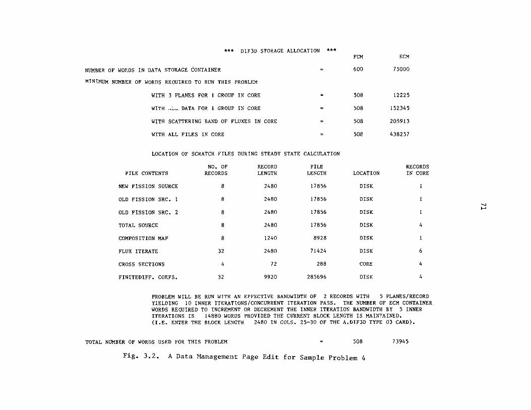
*** DIF3D STORAGE ALLOCATION ***
NUMBER OF WORDS IN DATA STORAGE CONTAINER
MINIMUM NUMBER OF WORDS REQUIRED TO RUN THIS PROBLEM
WITH 3 PLANES FOR 1 GROUP IN CORE
WITH DATA FOR 1 GROUP IN CORE
WITH SCATTERING BAND OF FLUXES IN CORE
WITH ALL FILES IN CORE
LOCATION OF
FILE CONTENTS
NEW FISSION SOURCE
OLD FISSION SRC. 1
OLD FISSION SRC. 2
TOTAL SOURCE
COMPOSITION MAP
FLUX ITERATE
CROSS SECTIONS
FINITEDIFF. COEFS.
SCRATCH FILES
NO. OFRECORDS
8
8
8
8
DURING STEADY
RECORDLENGTH
2480
2480
2480
2480
8
32
4
32
1240
2480
72
9920
STATE CALCULATION
FILELENGTH
17856
17856
17856
17856
8928
71424
288
285696
PROBLEM WILL BE RUN WITH AN EFFECTIVE BANDWIDTH OF 2 RECORDS WITH 5 PLANES/RECORDYIELDING 10 INNER ITERATIONS/CONCURRENT ITERATION PASS. THE NUMBER OF ECM CONTAINERWORDS REQUIRED TO INCREMENT OR DECREMENT THE INNER ITERATION BANDWIDTH BY 5 INNERITERATIONS IS 14880 WORDS PROVIDED THE CURRENT BLOCK LENGTH IS MAINTAINED.(I.E. ENTER THE BLOCK LENGTH 2480 IN COLS. 25-30 OF THE A.DIF3D TYPE 03 CARD).
TOTAL NUMBER OF WORDS USED FOR THIS PROBLEM = 508 73945
Fig. 3.2. A Data Management Page Edit for Sample Problem 4
FCM
600
508
508
508
508
ECM
75000
12225
152345
205913
438257
LOCATION
DISK
DISK
DISK
DISK
DISK
DISK
CORE
DISK
RECORDSIN CORE
1
1
4
1
6
4
4

72
3.9.2 Solution Options and Control Parameters - A.DIF3D 03 Card
Parameters supplied on the type 03 card of A.DIF3D select the problemtype (criticality or distributed inhomogeneous source) and the solution type(real or adjoint). Outei iteration control parameters which limit the maximumnumber of outer iterations, and optionally override the Chebyshev accelerationof the outers are also present. The outer iteration limit can be used tobypass the outers entirely and simply obtain selected integral edits. Inlarge problems requiring one or more restarts it is economical to requestthe integral edits only after convergence is achieved.
Two parameters on this card are related to the concurrent inner iterationstrategy (CIIS) which is invoked in large three-dimensional problems wheneverthe ECM container storage is insufficient for the one-group-in-core strategy(see Section 3.9.1). The first parameter is the minimum record size (MINBSZ)in long words for the I/O transfer of blocks of planes in the CIIS. The defaultvalues were chosen in an attempt to balance I/O overhead with the ECM storageoverhead incurred as the size of the blocks of planes increases (see Section3.10). The other parameter, the CIIS efficiency factor, avoids the last passof inner iterations in those groups for which the number of inner iterationsfalls below a code-dependent threshold. The following simple example illus-trates the point: suppose a bandwidth of 12 inner iterations can be performedin a single concurrent iteration I/O pass across the group-dependent data. Ifin a particular group the required number of inners/outer (mg) is 13, thenthe second I/O pass required to perform the single remaining inner iterationis scarcely cost effective.
Problems with thermal scattering frequently require upscatter iterationsto ensure convergence. The number of such upscatter iterations performedin every outer is specified on the type 03 card if the default value of 5upscatter iterations per outer iteration is inappropriate.
The job time limit entry on the type 03 card of A.DIF3D is intended toforce graceful termination (i.e. to ensure that restart files - RTFLUX andDIF3D - are saved) on those systems in which the amount of CPU time remainingis not an available quantity to subroutine TIMER. To prevent job failures dueto time limit, the user must specify a time limit on the type 03 card which issufficiently less than the job time limit to permit DIF3D to trigger a gracefultermination based on the elapsed time clock.
3.9.3 Convergence Criteria - A.DIF3D 05 and 06 Cards
Three outer iteration convergence criteria (Eqs. 2.89 - 2.91) are suppliedon the type 05 card of A.DIF3D:
1. Absolute eigenvalue change, Ek;
2. Pointwise fission source error, eX;
3. Average relative fission source error, Cq.
All criteria must be satisfied before the outer iterations are converged.When the default convergence criteria are used, the pointwise fission sourceconvergence is typically the last criterion satisfied.

73
Only one parameter related to the inner iteration convergence can bespecified by the user and it is on the type 06 card of A.DIF3D. This parameterspecifies the error reduction factor to be achieved by each series of inneriterations for each group during each outer iteration of the calculation.
Prior to the start of the outer iterations this factor is used along with the
precalculated optimum overrelaxation factors to compute the number of inneriterations required in each group. Experience has shown that this parameter
provides an effective means for ensuring uniform convergence behavior.
Included in the edits of every DIF3D problem will be the precalculatedoptimum overrelaxation factors and an iteration history in which the fission
source and k-effective convergence are tabulated. Figure 3.3 illustrates theouter iteration history page from Sample Problem 1.
3.9.4 Edit Options and Interface File Output - A.DIF3D 04 Card
The first four of the eleven edit options on the type 04 card of A.DIF3Dsimply provide edits of various input quantities and all but the first have
already been discussed in their respective applications. Key dimensions forgeometry and cross section data are edited along with boundary conditions,zone bucklings, mesh interval data and region to zone assignments.
Certain data are always edited. Included in this category are the dataspecified on the A.DIF3D file, the DIF3D data management page (a summary ofstorage allocation options), lists of interface files read or written, theouter iteration history, the optimum overrelaxation factors by group, and acomputing time summary which tabulates computation times by each logical com-
putation section in DIF3D.
Edit options five through nine provide integrals by region, region andgroup, and by group for neutron balance, power distribution and flux distribu-tion. Except for the neutron balance these items are also available by meshcell. All but power distribution data are available also for adjoint problems.
The mesh cell and energy dependent flux interface file RTFLUX (ATFLUXin adjoint problems) is always written upon termination of the outer iterations.The power-density-distribution-by-mesh-cell interface file PWDINT and thezone-averaged flux file RZFLUX can be optionally written in real problems byspecifying edit option ten.
DIF3D provides edits of commonly expected integral quantities. Allrequested edits that are not also written to one of the CCCC interface filesare written to the code-dependent interface file D3EDIT. Section 3.14 definesthese edit quantities.
Some users find it useful to obtain additional edits appropriate to theirapplications by writing programs which manipulate data available on the var-ious interface files described in this document. The UDOITL - UDOIT4 modulesdiscussed in Section 4.1.11 are appropriate for this application.

DIF3D 4.0 7/83 **** SAMPLE PROBLEM 1 **** 2D SNR BENCHMARK - RODS IN - FD06
OUTER ITERATION SUMMARY REAL SOLUTION K-EFF. PROBLEM
OPTIMIZED INNER ITERATION STRATEGY
GROUP OPTIMUM NO. OF GROUP OPTIMUM NO. OF GROUP OPTIMUM NO. OFNO. OMEGA INNERS NO. OMEGA INNERS NO. OMEGA INNERS
OUTERIT. NO.
1
2
3
4
5
6
7
8
9
10
11
12
13
14
15
1.42092D+00 7
REL. POINTERROR
6.055469D-01
4.704232D-01
1.767146D-01
8.690130D-02
3.722962D-02
1.064050D-02
3.829818D-03
1.806451D-03
4.606560D-04
1.203257D-04
2.823481D-05
1.556538D-05
4.066891D-06
9.684399D-07
2.049522D-07
1/05/84 2222.100 PAGE 28
GROUP OPTIMUM NO. OFNO. OMEGA INNERS
2 1.57656D+00 11 3 1.27169D+00 5 4 1.26615D+00 5
REL. SUM EIGENVALUECHANGE
5.676263D-02
3.391310D-02
1.908419D-02
8.680460D-03
5.107754D-03
2.468417D-03
8.781398D-04
2.399321D-04
9.278793D-05
3.893697D-05
1.050205D-05
2.427902D-06
7.286502D-07
3.097159D-07
8.601389D-08
ERROR
1.686693D-01
1.306399D-01
7.337978D-02
4.552007D-02
2.073863D-02
6.314254D-03
2.1976601-03
1.012883D-03
2.320342D-04
7.173725D-05
1.472779D-05
1.031790D-05
1.710762D-06
7.739674D-07
1.272518D-07
POLY.ORDER
0
0
0
2
3
2
3
4
2
3
4
DON. RATIO
USED
0.0
0.0
0.0
5.957153D-01
5.957153D-01
5.957153D-01
6.280142D-01
6.280142D-01
6.280142D-01
6.280142D-01
6.331385-01
6.331385D-0 1
6.331385D-01
6.331385D-01
6.577679D-01
DOM. RATIO
ESTIMATED
0.0
8.269922D-O1
5.957153D-01
5.957153D-01
6.254009D-01
6.280142-01
6.280142D-01
6.305913D-01
6.203958D-01
6.331385D-O1
6.331385D-01
7.953652D-01
6.304855D-01
6.577679D-01
6.577679D-01
K-EFFECTIVE
1.05676263D+00
1.09067574D+00
1.10975993D+00
1.11844039D+00
1.12354814D+00
1.12601656D+00
1.12689470D+00
1.12713463D+00
1.12722742D+00
1.12726635D+00
1.12727686D+00
1.12727928D+00
1.12728001D+00
1.12728032D+00
1.12728041D+00
OUTER ITERATIONS COMPLETED AT ITERATION 15, ITERATIONS HAVE CONVERGED
K-EFFECTIVE - 1.12728040833
TO RESTART THIS CALCULATION, INPUT FOLLOWING VALUES
DOMINANCE RATIO (SIGBAR) - 6.577679231397D-01
OPTIMIZED OVER-RELAXATION FACTORSGROUP OPTIMUM GROUP OPTIMUM GROUP OPTIMUM GROUP OPTIMUM GROUP OPTIMUM
NO. OMEGA NO. OMEGA NO. OMEGA NO. OMEGA NO. OMEGA
1 1.42092D+00 2 1.57656D+00 3 1.27169D+00 4 1.26615D+00
MAXIMUM POWER DENSITY 2.68379D-04 OCCURS AT MESH CELL (IJ,K) - ( 1, 1, 1)
PEAK POWER DENSITY IS CALCULATED BY SAMPLING THE AVERAGE FLUX VALUES ON THE CELL SURFACES .dND WITHIN THE CELL.
Fig. 3.3. Iteration History Page Edit for Sample Problem 1.

75
3.9.5 Restart Option - A.DIF3D 03, 06 and 07 Cards
Restart jobs generally differ from the original job in two ways. Theappropriate flux DATASET (RTFLUX or ATFLUX) must be provided and specifiedunder "BLOCK=OLD" in the BCD input data. Appropriate JCL designations arerequired to ensure that the system accesses the appropriate restart flux file.Optimum overrelaxation factors and the latest eigenvalue and dominance ratioestimates should also be provided. The most convenient means for specifyingthe last three items is to supply the restart file DIF3D and specify it under"BLOCK=OLD". Note that the restart sentinel will already be set on the DIF3Dfile if the file was written by a job in which outer iteration convergence wasnot achieved. An alternative is to revise the original A.DIF3D file by
specifying the above data on card types 06 and 07 and by specifying therestart sentinel on the type 03 card.
The precalculation of optimum overrelaxation factors generally requires
CPU time equivalent to two or three outer iterations, so that it is well worth
the effort in problem restarts to supply these factors. The remaining factors
supplied during restarts facilitate resumption of the Chebyshev fission sourceacceleration with minimal loss of efficiency. In applications in which a
series of related problems are to be solved the optimum overrelaxation factors
frequently are quite similar. Ccanequently the optimum overrelaxation factors
for a common set of problems may be calculated once in the first problem ofthe set and used throughout.
3.9.6 Acceleration of Near-Critical Source Problems - A.DIF3D 08 Card
An optional strategy which accelerates the outer iteration convergence in
near-critical systems with an inhomogeneous source (see Section 2.2.8) can be
invoked by specifying the appropriate data on the type 08 card of A.DIF3D.
The strategy provides more rapid convergence for this class of problems thanthe Chebyshev acceleration techniques generally applied to most DIF3D problems.
3.9.7 Neutron Transport Option - A.DIF3D 09 Card
At Argonne there exists a version of DIF3D in which the diffusion theoryinner iteration routines have been replaced by a transport theory (Sn) calcu-lation. As of the date of this report there were no plans to make a formalrelease of DIF3D/transport to any code centers.
One invokes DIF3D/transport in the Argonne system by including
PRELIB='Cl 6.B99983.MODLIB'
on the EXEC card for STPO21. The type 09 card of A.DIF3D specifies the trans-port option. It contains the Sn order as well as the control parameters forthe innermost line-sweep iteration.
3.10 Guidelines for the Efficient Use of the CIIS
Typical problems invoking the Concurrent Inner Iteration Strategy (CIIS)(see Section 4.3.2.2) make heavy demands on computing system resourcesincluding:

76
1. CPU Time,
2. I/O Processor Time (EXCP's on IBM systems),
3. Central Memory Storage (FCM and ECM),
4. Disk Storage.
Items (1) and (4) are essentially invariant for a given problem, while items(2) and (3) are dependent on the ECM storage container size. Item (2) is alsodependent on MINBSZ, the desired I/O record size (see Section 3.9.2). Withinpractical limits, resources (2) and (3) are roughly inversely proportional, sothat as the ECM size increases, the inner iteration bandwidth B increases,yielding a corresponding decrease in the number of inner iteration I/O passesand vice versa. This flexibility in resource allocation afforded by the rangeof permissible ECM values enables the user to tailor the resource utilizationfor an arbitrary problem to an arbitrary host installation.
3.10.1 Optimal ECM Size Estimation - A.DIF3D 02 Card
If a reasonable estimate exists for M, the average number of inner itera-tions per outer iteration required for the problem at hand, then the procedurebelow determines the least storage needed to minimize the number of inneriteration I/O passes having block size MINBSZ. For example, if M=24 in a givenproblem but the maximum ECM-containable inner iteration bandwidth B is B=18,then the algorithm will choose U, the number of ECM-contained I/O blocks, andL, the number of planes in an I/O block, such that B=U'L > 12. A bandwidthof 12 iterations requires the least ECM storage to perform the inner iterationsin two I/O passes.
The four-step procedure detailed below, provides simple guidelines forusers to obtain a quick estimation of the appropriate ECM container size for aproblem that may need the CIIS option. Formulas and parameter definitionsare tabulated in Table 3.3 for short-word and long-word machines and formachines with one- or two-level storage hierarchies. Figure 3.4 graphicallydepicts ECM storage requirements W(U,L) as a function of the number of ECM-contained blocks U for blocks ranging in size from L=1 to L=15 planes.Constant bandwidth (dashed) curves, B=U-L, B=5,10,...,50 are also plottedto clearly indicate the relative storage overhead incurred as the block size Lis increased.
The ECM estimation procedure is given by the following four steps:
Step 1: Determine the maximum container space available for the variablesize plane-block arrays,
WMAX = ( min (ECMMAX, ECM'G) - ECMISC ) / (IM*JM)
WMAX is limited by either the machine dependent maximum ECM size(ECMMAX) or by the minimum container size (ECM1G) for the one-groupcontained data management option.

77
TABLE 3.3. ECM Size Estimation for the CIIS
Parameter Definitionsa
M = Maximum number of inner iterations (mg) per outer in any group.BLMAX = Maximum ECM system buffer length (usually 3 27 6 8 ).b
INDEXR = ECM space required for dynamic random access I/O index in XCM.MACHUPEc = 3000K bytes on the IBM 370/195 at ANL.
= 8000K bytes on the IBM 3033's at ANL.= 393216 LCM words on the CDC 7600 at LBL.= 294912 words of LCM on the CDC 7600 at BNL.
MACHUPFC = 61440 words of SCM on the CDC 7600.PROGSIZE = Memory required to contain longest overlay in DIF3D.ECMISC (9+MAXSCT)*NCMP+I*J
ECMMAX = jMACHUPE-FCM-PROGSIZE on the IBM 370/195.IMACHUPE-FCM-PROGSIZE-BLMAX-INDEXR(L) on the CDC 7600.
ECM1G = ECMISC+(8+1/LDW)*NCELLSINDEXR(L) = Q(L)*(5*NGROUP+9) + NGROUP
Q(L) = (K-1)/L+1W(U,L) = (min(U+2, Q(L))*5 + min(U+3, Q(L)) + 4.5)*L
ECM Estimation Algorithm Summary
1) WMAX = ( min (ECMMAX, ECM1G) - ECMISC) / (IM*JM)2) L = min ( MINBSZ/(I*J)+.5, K, WMAX/W(1,1) )3a) U = max U subject to W(U,L)(WMAX (graphical estimate Fig. 3.4.)3b) P = (M-1)/(L*U) + 13c) U = (M-1)/P + 14)ECMCC = ECMISC + W(U,L)*I*J
aSee Table 3.2 for additional parameter definitions.
bOn the LBL system default system buffer sizes are overridden by the FBSIZEand GBSIZE control cards.
cMACHUPn is the estimated maximum storage available to the user for the ECMcontainer (n=E) or FCM container (n=F).

78
500
O (U, L) PARAMETER DOMAIN-- L =NUMBER OF MESH PLANES PER I/O BLOCK
- - - B= U -L, THE CIS BANDWIDTH (IN MESH PLANES)
W(U, L)= (6- U +175) -L
400
300-
,44
200--
N B=50
100 --
B=10
0 5 10 15
U: NUMBER OF ECM-CONTAINED I/O BLOCKS
Fig. 3.4. CIIS ECM Storage Requirements Guide
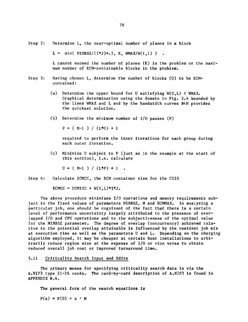
79
Step 2: Determine L, the near-optimal number of planes in a block
L = min( MINBSZ/(I*J)+.5, K, WMAX/W(1,1) ) .
L cannot exceed the number of planes (K) in the problem or the maxi-mum number of ECM-containable blocks in the problem.
Step 3: Having chosen L, determine the number of blocks (U) to be ECM-contained:
(a) Determine the upper bound for U satisfying W(U,L) < WMAX.Graphical determination using the domain in Fig. 3.4 bounded bythe lines WMAX and L and by the bandwidth curves BM providesthe quickest solution.
(b) Determine the minimum number of I/O passes (P)
P = ( M-1 ) / (L*U) + 1
required to perform the inner iterations for each group duringeach outer iteration.
(c) Minimize U subject to P (just as in the example at the start ofthis section), i.e. calculate
U = ( M-1 ) / (L*P) + 1 .
Step 4: Calculate ECMCC, the ECM container size for the CIIS
ECMCC = ECMISC + W(U,L)*I*J.
The above procedure minimizes I/O operations and memory requirements sub-ject to the fixed values of parameters MINBSZ, M and ECMMAX. In analyzing aparticular job, one should be cognizant of the fact that there is a certainlevel of performance uncertainty largely attributed to the presence of over-lapped I/O and CPU operations and to the subjectiveness of the optimal valuefor the MINBSZ parameter. The degree of overlap (concurrency) achieved rela-tive to the potential overlap attainable is influenced by the resident job mixat execution time as well as the parameters U and L. Depending on the chargingalgorithm employed, it may be cheaper at certain host installations to arbi-trarily reduce region size at the expense of I/O or vice versa to obtainreduced overall job cost or improved turnaround time.
3.11 Criticality Search Input and Edits
The primary means for specifying criticality search data is via theA.NIP3 type 21-26 cards. The card-by-card description of A.NIP3 is found inAPPENDIX B.4.
The general form of the search equations is
P(x) = P(O) + x * M

80
where P is the quantity being varied. The user must specify the followingdata:
1. the parametric modifiers M of the search quantity P
2. bounds for and two initial estimates of the search parameter x
3. the desired search k-effective, kd;
4. the search k-effective convergence criterion (EPSRCH);
5. the maximum number of search passes permitted.
The alternative to criticality search data specification via A.NIP3 is tosupply the CCCC standard interface file SEARCH. The SEARCH file descriptionprovided in APPENDIX C indicates the subset of SEARCH options implemented atANL and the corresponding ANL modifications to SEARCH.
The code block GNIP4C reads A.NIP3 and writes a SEARCH file when theappropriate type 21-26 cards are present.
3.11.1 Parametric Modifiers M - A.NIP3 23-26 Cards
The desired search option is indicated by the presence of one of the fourmutually exclusive A.NIP3 type 23-26 cards. DIF3D currently permits only anuclide concentration search via the type 23 card of A.NIP3.
The nuclide concentration search operates on subzone volume fractions,modifying the net atom densities in each zone (composition) to which the modi-fier subzone is assigned. Modifier subzoiies and the zones they modify areboth specified on the type 23 card of A.NIP3.
3.11.2 Search Parameter Estimates x - A.NIP3 22 Card
Two initial estimates for the criticality search parameter and upper andlower bounds for the search parameter during the course of the search arespecified on the type 22 card of A.NIP3. The search problem should be formu-lated such that the magnitude of the search parameter estimate satisfies(.1<x<.0) for best performance of the parabolic interpolation option of thesearch procedure. The A.NIP3 type 22 card is optional.
3.11.3 Search Pass Control Parameters - A.NIP3 21 Card
Search passes are normally terminated by one of four conditions:
1. search convergence; .
2. the maximum number of search passes reached;
3. computing time limit detected;
4. the search parameter out of range.

81
The user specifies the desired k-effective, the relative k-effective errorbound (EPSRCH) and the maximum number of search passes on the type 21 card ofA.NIP3. Specification of the search parameter range restrictions is discussedin the previous section.
From an efficiency standpoint it is recommended that the neutronics cal-
culation k-effective convergence criterion (6k) be no more than an order ofmagnitude tighter than EPSRCH during the search passes. Upon search convergence
the flux can be more tightly converged via an appropriate restart of the
neutronics problem.
3.11.4 Search Restarts - A.NIP3 21 and 22 Cards
In the event of abnormal termination, or if tighter k-effective
convergence is desired, the search pass loop may be efficiently restarted bysupplying the appropriately saved SEARCH, RTFLUX and DIF3D files and byspecifying them under "BLOCK=OLD" in the BCD input data. Data supplied on thetype 21 and 22 cards of A.NIP3 will override corresponding data items on theexisting SEARCH file.
3.11.5 Search Edits - A.NIP3 21 Card
An edit of a newly created or a previously existing SEARCH file may be
obtained from GNIP4C via a sentinel on the type 21 card of A.NIP3. Sentinelsfor editing the search parameter data and the search quantity at each search
pass are also provided on the type 21 card of A.NIP3.
A sentinel provided on the type 04 card of A.DIF3D permits user controlof the frequency of the DIF3D neutronics edits. The latter edits are usually
deferred until search convergence.
3.12 Running DIF3D
3.12.1 Input and Output Interface Datasets
The BCD and binary input and output files potentially encountered during
the execution of DIF3D are tabulated in Table 3.4. User input and output
options are such that only a problem dependent subset of these files arerequired. The next several subsections address details pertinent to theexecution of DIF3D on specific classes of host system environments. Much ofthis discussion is based on DIF3D implementation experience gained on computerswhich are representative of each environment class.
3.12.2 Sample Input
Figure 3.5 illustrates a job input deck for Sample Problem 1 in the
National Energy Software Center (NESC) package (see Section 5.3). The microscopiccross section file ISOTXS is supplied in BCD card image form via the A.ISOfile. In typical production applications the ISOTXS binary interface file is
usually specified under BLOCK=OLD since it is generated by appropriate crosssection processing codes. The remaining interface file data is specifiedusing free format input.

82
TABLE 3.4. DIF3D Interface Files (CCCC and code-dependent)
BCD Binary Modea Contents
GEODSTb I/S Model GeometryNDXSRF I/S Composition definition
A.NIP3 ZNATDN I (Sub) Zone atom densitiesFIXSRC I Distributed inhomogeneous sourceSEARCH 1/R Criticality search specifications
A.ISO ISOTXS I Microscopic cross sectionsXS.ISO I Converted to ISOTXS by CSE010
A.HMG4C I HMG4C control parametersCOMPXSb I/S Macroscopic cross sections
A.DIF3D DIF3Db I/R DIF3D control parameters
A.LASIP3 I LASIP3 input processor data
RTFLUXd O/R Real fluxATFLUXd O/R Adjoint fluxNHFLUXe O/R Nodal real solution vectorsNAFLUXe O/R Nodal adjoint solution vectorsRZFLUX 0 Real zone averaged fluxPWDINT 0 Power densityPKEDIT 0 Peak power and flux by mesh cellD3EDIT 0 DIF3D integral edits
aFile usage (I=Input, O=Output, R=Restart, S=Modified by SRCH4C)
bBinary input files ultimately required by DIF3D.
cCan be created from ISOTXS, NDXSRF and ZNATDN by HMG4C.
dBinary output files required by DIF3D (RTFLUX and/or ATFLUX).
eBinary output files required by DIF3D nodal option (NHFLUX and/or NAFLUX).
//SAMPLEl JOB REGION=1200K,TIME=3,CLASS=W//*MAIN ORG=PRO,LINES=10
// EXEC ARCSPO21,RTFLUX='C116.B20245.SAMPLE.RTFLUX',// RTCYL=1,RTDSP=(NEW,CATLG)//SYSIN DD *BLOCK=STPO21NOSORT=A.ISO
<A.ISO dataset is listed in Fig. 5.1>
UNFORM=A.NIP3
<A.NIP3 dataset is listed in Fig. 5.1>
UNFORM=A.DIF3D
<A.DIF3D dataset is listed in Fig. 5.1>
Fig. 3.5. ANL DIF3D Input Skeleton for Sample Problem 1
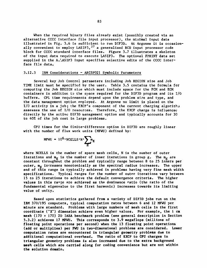
83
When the required binary files already exist (possibly created via analternative CCCC interface file input processor), the minimal input dataillustrated in Fig. 3.6 is sufficient to run DIF3D. At Argonne it is occasion-ally convenient to employ LASIP3,3 7 a generalized BCD input processor codeblock for CCCC standard interface files. Figure 3.7 illustrates a skeletonof the input data required to execute LASIP3. The optional FPRINT data setsupplied in the A.'ASIP3 input specifies selective edits of the CCCC inter-face file data.
3.12.3 IBM Considerations - ARCSPO21 Symbolic Parameters
Several key Job Control parameters including Job REGION size and JobTIME limit must be specified by the user. Table 3.5 contains the formula forcomputing the Job REGION size which must include space for the FCM and ECMcontainers in addition to the space required for the DIF3D program and its I/Obuffers. CPU time requirements depend upon the problem size and type, andthe data management option enployed. At Argonne no limit is placed on theI/O activity in a job; the EXCP's component of the current charging algorithmassesses the use of I/O resources. Therefore, the EXCP charge is influenceddirectly by the active DIF3D management option and typically accounts for 30to 40% of the job cost in large problems.
CPU times for the finite-difference option in DIF3D are roughly linearwith the number of flux work units (MFWU) defined by:
MFWU - 106NCELLS*N' mg
where NCELLS is the number of space mesh cells, N is the number of outeriterations and mg is the number of inner iterations in group g. The mg areconstant throughout the problem and typically range between 8 to 25 inners perouter, mg increases monotonically as the spectral radius increases. The upperend of this range is typically achieved in problems having very fine mesh widthspecifications. Typical ranges for the number of outer iterations vary between15 to 25 iterations to achieve the default convergence criteria. The highervalues in this range are achieved as the dominance ratio (the ratio of thefundamental eigenvalue to the first harmonic) increases towards its limitingvalue of unity.
Based upon statistics gathered from a variety of DIF3D jobs run on theIBM 370/195 computers, typical computation rates between 6 and 12 MFWU perminute are standard. Problems with large numbers of mesh cells in the firstcoordinate ("X") dimension achieve even higher values. For example, the 1 cmmesh (170 x 170) 2D IAEA benchmark problem (see general description in Section5.3.2) achieves 17 MFWU. This corresponds to 3.9 megaflops (millions offloating point operations per second) when the 13 floating point operations(add or multiplies) per FWU in two-dimensional problems are considered. Lowercomputation rates are encountered in triangular geometry problems due toadditional computational overhead. The ratio of EXCP to CPU charges intriangular geometry problems is also increased due to the extra backgroundmesh cells which are carried along for coding convenience but are not withinthe solution domain.

84
BLOCK-OLDDATASET-GEODSTDATASET-ISOTXSDATASET=NDXSRFDATASET-ZNATDNBLOCK-STPO21UNFORM-A.DIF3D
/*
Minimal Input Data Example
BLOCK-OLDDATASET-NDXSRFDATASET=ZNATDNBLOCK-STPO21UNFORM=A.DIF3D
.
NOSORT-A.LASIP35000
OV FPRINT1D 40002D GEODST 00002D ISOTXS 00323D 1 4 54D 1 42D NDXSRF 00002D ZNATDN 0000
/ (6X,416) BPOINTER container size (see Section 3.13)
///////
Process four files with the printPrint all GEODST record typesPrint three record types and two isotopesISOTXS record types to be printedISOTXS isotopes to be printedPrint all NDXSRF record typesPrint all ZNATDN record types
OV GEODST
OV ISOTXS
STOP/*
LASIP-3 Input Skeleton
Fig. 3.6.
Fig. 3.7.

85
TABLE 3.5. Job Region Size and Dataset SpaceEstimation for ARCSPO21
Parameters
NCELLS -NDIM -NGROUP =NGUP =S =
=
ECM =PROGSIZE -
Number of mesh cells in the problemNumber of problem dimensions (1, 2 or 3)Number of energy groupsFirst group with nonzero upscatter source2*NDIM-0, number of orthogonal geometry surfaces2*NDIM-1, number of triangular geometry surfacesECM or FCM container sizea325K bytes, the storage required for DIF3D programand I/O buffers
REGION - (ECM+FCM)/128 + PROGSIZE = JOB CARD Region Size
Data Set Space Allocation Estimation
ARCSPO21SymbolicParameters
DatasetName FT XXF001
StorageEstimateCylinders
group inde-pendent data
ZONMAP
46-49,51,=55,5652 -
NCELLS*8/CYLSIZc
FL CYL/2
RTCYL(5)ATCYL(5)PSICYL(5)PSICYLPSICYL
PSUCYL(3)
FDCCYL(20)DMY1CYL(21)
DMY2CYLDMY2CYL(7)DMY2CYL
DMY5CYL(5)SRFCYL(12)
RTFLUXATFLU XPSINEWPSIOLDFSRC
3031414254
NGUPI - FL EYL*NGROUP
43 - FL CYL*(NGROUP+1-NGUP)
FDCOEF 45 - PSICYL*(NDIM+1)&&DUMMY1 DUMMYL - FDCCYL+ZONCYL
&&DUMMY2&&DUMMY3&&DUMMY4
DUMMYM5SCRO01SCRO02
DUMMY2DUMMY3?DUMMY4
DUMMY66,67
PSICYL+FL YL*2
- PSUCYL+FLXEYL- 2*NCELLS*(S+1)/CYLSIZ
aRefer to Table 3.2.
bSymbolic parameter defaults are enclosed in parenthesis.
cCYLSIZ is dependent on device type and block size.When the BLKSIZE-6136, CYLSIZ-12280*19 on a 3330 disk(CYLSIZ=18416*30 on a 3350 disk).
FL EYL(1)
ZONCYL(1)

86
Many files are accessed during the course of a DIF3D calculation and eachof them requires a Data Definition (DD) card to describe the file characteris-tics including size allocations, disposition, volume identification, DCBinformation and the dataset name. To simplify the input deck for users of theANL IBM computers a cataloged procedure (ARCSPO21) was written (see listing inAppendix A). Symbolic procedure parameters in ARCSPO21 permit convenient userspecification of key parameters for various DD cards without recoding theentire DD statement. Comments within the ARCSPO21 procedure tabulate thedefault values and usage of the symbolic parameters and the logical unit num-bers (FTnnFOO1) to which they apply. Several symbolic parameters deserve spe-cial attention and are described in the following paragraphs.
The default value (RECFM-U) of the symbolic parameter MODEDCB designatesthirteen files as random access I/O files to the I/O package (SIO) employed byDIF3D. An attempt to minimize disk head contention is made by suballocatingthese files in a particular ordering among the five available scratch diskvolumes at ANL. The user must override the default space allocations forthese files when the space estimation formulas in Table 3.5 indicate thedefault values are insufficient. The formulas provide allocation estimatesfor the thirteen individual files, for RTFLUX and ATFLUX files, and for thefive dummy datasets on which the thirteen scratch files are suballocated.When estimating the cylinder sizes for the dummy datasets all fractions mustbe rounded to the next highest integral number of cylinders. Appropriatecylinder sizes are edited for all ARCSPO21 parameters immediately before thedata management summary page.
The parameters UNITSCR-SASCR and UNITS-BATCHDSK denote the system scratchdisk volumes and the pool of disk volumes on which datasets can be cataloged,respectively. The latter designation is given to files which are deemedlikely to be cataloged by a user.
All files but the thirteen random access files are given block sizeparameters appropriate to their anticipated I/O activity. When explicitlyoverriding JCL for any file care must be exercised to specify block sizesappropriate to the output device type so as to avoid inefficient use ofstorage space.
Insufficient disk storage for extremely large jobs require users to assignthe largest scratch file FT45FOO1 to a 6250 BPI scratch tape. In this eventthe entire DD card is overridden with the following alternate specification:
//FT45F001 DD UNIT-READ6250,SUBALLOC-,// DCB-(RECFM-VBS,LRECL-X,BLKSIZE-12280,DEN-4)
If the j.ob using a scratch tape 'has the possibility of running on OS/MVT(i.e. the IBM/195), then some additional JCL is needed to prevent the operatorfrom issuing a tape save request which assigns the tape to the user's account.The following two steps are recomended:
1. Add the following JCL as the first step of the job
//STEP! EXEC PGM-IEFBR14//$$NOSAVE DD VOL-SER-,UNIT-READ6250,DISP(NEW,PASS),// DCB-(RECFM-VBS,LRECL-X,BLKSIZE=12280,DEN-4)

87
2. then override the FT45FOO1 card:
//FT45F001 DD UNIT=READ6250,SUBALLOC=,// VOL=REF=*.STEP1.$$NoSAVE,DISP=(NEW,DELETE),// DCB=(RECFM=VBS,LRrlCL=X,BLKSIZE=12280,DEN=4)
3.12.4 CDC 7600 Considerations
Figures 3.8 and 3.9 illustrate the structure of a typical job to beexecuted on the CDC 7600 at Lawrence Berkeley Laboratory (LBL) and at BrookhavenNational Laboratory (BNL), respectively. The problem to be solved is identicalto that shown in Figure 3.5. As in the latter example for IBM systems, theassumption is made that an absolute overlay module already exists and in thisexample is merely "STAGEd in" from a magnetic tape library.
When the DIF3D absolute overlay module is created, minimum field lengthrequirements for all subsequent executions of this module can be easilyobtained by scanning the loader map for the maximum SCM and LCM field lengths.These field lengths are dynamically requested prior to invoking DIF3D usingeither the SFL card at LBL or the RFL card on "off the shelf" CDC systemssuch as the system at BNL. A nominal field length sufficient to perform thestaging is specified on the JOB card in these examples.
Additional SCM or LCM field length required for BPOINTER containers sub-sequently used in DIF3D is dynamically allocated and deallocated appropriatelyduring the execution. In fact, the user must not preallocate space forthe BPOINTER containers since DIF3D only uses space dynamically allocatedby DIF3D. Error messages result when insufficient field length is availablefor dynamic allocation. Consequently, the user never needs to compute theSCM and LCM field lengths associated with the BPOINTER container sizes.
On standard CDC installations such as the one at Brookhaven NationalLaboratory, less SCM space is demanded by the I/O buffers. About 70,000 octalSCM words are required, thereby permitting a substantial increase in the FCMcontainer size.
Upper bounds for computing units (CU's) at LBL or Central Processor (CP)seconds at BNL are also required on the JOB card. Estimates of CP seconds forthe CDC 7600 are from 10 t 25% less than the corresponding estimates for theIBM 370/195 (see Section 3.12.3). The CU's quantity at LBL is defined as
CU-3*CP+.5*BLD+ITO.
The BLD quantity is discussed below. The interference to others (ITO) quantitymeasures the efficiency of the utilization of system resources acquired by ajob. Figuring heavily in the ITO computation is the LCM size and the frequencyof I/O requests.
The relatively simple Job Control Language on CDC systems simplifies theuser's dealings with the many binary files required by DIF3D. Two I/O relatedconsiderations, however, are pertinent to execution at LBL.
A significant fraction of the cost of executing jobs requiring largeamounts of disk to ECM data transfers is based on the number of buffer loads(BLD). Therefore it is desirable to reduce the number of BLD's by increasing
the size of LCM system buffers for the large files when they are not core-contained. This is accomplished via the control card
FBSIZE,filename-m.

88
LBLJOB,7,600,10000.xxxxxx,usernameGBSIZE,20.GETTAPE,DIF3D/*,nnnnn.GBSIZE,5.FBSIZE,DIF3D=100.SFL,120000,1.DIF3D,LC=77777.FILES.7-8-9 END-OF-RECORD CARDBLOCK-STPO21NOSORT=A.ISO
(See A.ISO DATASET specified in Fig. 5.1>
UNFORM=A.NIP3
<See A.NIP3 DATASET specified in Fig. 5.1>
UNFORM-A.DIF3D
<See A.DIF3D DATASET specified in Fig. 5.1>
6-7-8-9 END-OF-INFORMATION CARD
Fig. 3.8. Structure of Job Deck for CDC 7600 at LBL
BNLJOB,T400,CM20000.STAGE,DIF3DUB,E,PE,VSN-KXXXX.REWIND,DIF3DUB.COPYBF,DIF3DUB,DIF3D.RETURN,DIF3DUB.RFL,70000,L-1.DIF3D.7-8-9 END OF RECORD CARDBLOCK-STPO21
<See identical input data record in Fig. 3.8.>
6-7-8-9 END-OF-INFORMATION CARD
Fig. 3.9. Structure of Job Deck for CDC 7600 at BNL

89
where filename is the appropriate file name and m is the buffer size ii unitsof 1000 words. m=100 is recommended for large files. In all problems it isrecommended that a global buffer Lize value be changed to 20 by the controlcard
GBSIZE=20.
as in the example in Figure a.8, thereby attempting to reduce the BLD costsfor all files.
The control card, FILES, provides detailed information concerning theBLD's and sectors required by each file in a job, and is useful for determiningthe distribution of I/O costs by file name. If used it should be inserted atthe end of the control card record.
The control card
DISKHOG,n.
is required to override the default limit of 4000 sectors when problems whichuse more than 4000 disk sectors must be executed. The DISKHOG card should beinserted after the JOB card.
An estimate of the number of sectors, n, required by a given job can beobtained from the following formula
n = 1.1 * NCELLS * 2 + NGROUP * (5+NDIM)
where the variables are defined in Table 3.2. The estimate for n is made withthe assumption that the major scratch files on logical units (41, 42, 45, 48,49 and 53) are on disk.
3.12.5 Multiple Problems and Restarts - RTFLUX and DIF3D
Practical economic reasons necessitate the inclusion of a restart capa-bility in DIF3D. This feature primarily permits the resumption of the outeriteration process from the point of termination by employing the RTFLUX(ATFLUX) file saved when the previous job terminated (gracefully). It is alsoadvantageous to supply the optimum overrelaxation factors during restartsbecause they account for 5 to 10% of the cost in most calculations withoutrestarts. The simplest way to supply these factors is to save the DIF3Drestart dataset named DIF3D. It contains the DIF3D control parameters, themost recently updated k-effective and dominance ratio estimates, and theoptimum overrelaxation factors.
For certain classes of problems it is economical to retain a fixed set ofoptimum overrelaxation factors for the entire set of similar jobs. These fac-tors are always identical for real and adjoint calculations of a given problemconfiguration. Control rod worth studies as well as many criticality searchproblems frequently yield practically identical convergence rates with theinitially computed set of optimum overelaxation factors.
From time to time users attempt to reduce computing times by starting offwith an initial flux guess which is the converged solution of a related

90
problem configuration. This is probably most effective in near-critical fixedsource problems where the magnitude of the flux is an important factor. Prob-lems requiring thermal iterations are likely to benefit from this practice also.However, situations have been encountered where the use of initial flux guessesrequire additional outer iterations to satisfy the same convergence criteriaas that attained by a similar calculation with an initial flat flux guess.
It is sometimes convenient to stack similar model cases in a single jobstep by employing successive sets of BLOCK-STPO21 data blocks. Unless expli-citly REMOVEd by an appropriately placed REMOVE=filename input command, previ-ously created, binary and BCD files remain in existence. Consequently, thebinary interface file ultimately to be changed must be explicitly removed sothat the modified file can be created. Typical candidates here are the CCCCinterface files GEODST, COMPXS, NDXSRF and/or ZNATDN.
3.13 LASIP3 CCCC Standard Interface File Processor
LASIP337 Will permit the specification and editting of all CCCC interfacefiles. In the Argonne implementation of LASIP3, two additional card-imagesmust immediately precede the normal LASIP3 input data specified in Ref. 37.The first of these card-images must be the NOSORT-A.LASIP3 card which signalsthe start of LASIP3 input. The second contains BPOINTER control informationand a data item LASTCL that indicates the number of columns (default-72) to beprocessed by the LASIP3 free-field input processor. The card has the format(6X, 416) and contains the four data items: MAXSIZ, MAXBLK, IPRINT andLASTCL. MAXSIZ is the FCM container size in long (REAL*8) words. MAXBLK isunused. IPRINT is the BPOINTER debugging sentinel and has input options iden-tical to those described on the A.DIF3D type 02 card. A MAXSIZ value of 5000to 10000 is usually quite adequate for most applications. However, aconservative approach is simply to supply a container size bounded by the sumof the FCM and ECM sizes on specified in A.DIF3D. Figure 3.7 contains anexample of data set A.LASIP3.
3.14 Definitions of Output Integral Quantities
As noted in Section 3.9.4, DIF3D provides optional edits of commonlyexpected flux integral quantities. Five sentinels (items 5-9) on the type 04card of dataset A.DIF3D provide the user with the ability to select thedesired subset of edits. The sentinels for items 5, 6 and 7 are multidigitnumbers which permit edits by region and/or group, and by mesh cell and/orgroup (see Appendix B.1).
The definition of the various integrals for each of the five major editoptions are tabulated separately and in the order of their appearance in theindividual edits. A preliminary subsection is devoted to establishing thedefinitions and notation for the integral forms used in the tabulation. Anexplanation of the iteration history page is also included.
3.14.1 Iteration History Quantities
In multidimensional geometries the iteration history page begins with atabulation of the group-dependent inner iteration optimum overrelaxation fac-tors wg together with m the corresponding fixed number of inner iterationsper outer iteration. These factors are absent in the one-dimensional casebecause the resulting tridiagonal inner iteration matrix is solved directly.

91
Following the optimum factor edit, a one-line summary of key parametersfor each outer iteration is printed. The first three items are outer itera-tion convergence criteria:
1) the relative pointwise fission source error,
T(n) -_a(n)
EXn * 2 , (3.7)
monitors the pointwise eigenvector convergence;
2) the relative fission source sum error,
E (n)= I(n -(n-1) 1(3
( (nn)-112' 38
monitors the average eigenvector convergence;
3) the eigenvalue change,
(n) k (n-l)(3.9)k keff keff'
is a measure of the eigenvalue convergence.
Next in appearance are three items pertinent to the Chebyshev acceleration ofthe outer (power) iterations:
1) the order p of the Chebyshev polynomial in the current extrapolationcycle;
2) o, the dominance ratio estimate for a to be used in Eq. (2.61);
3) a' is the most recent update for the dominance ratio estimate (seeEq. 2.84).
When the Chebyshev acceleration is not applied, p and a will be zero.
The last item on each history line is ken which is computed duringouter iteration n (see Eq. 2.92), except during external source problems in
which case ken) = is constant and is followed by the (unnormalized) total
fission source integral for the reactor. In fixed source problems thedominance ratio estimates are replaced by the spectral radius estimates of theouter iteration matrix.

92
Upon termination of the outer iterations one of three messages appear:
1) outer iterations converged;
2) maximum number of outer iteration achieved;
3) time limit exceeded.
This message is followed by the most recent eigenvalue estimate and a summaryedit of the parameters needed for a subsequent restart of the terminatingDIF3D job.
In most problems the relative pointwise fission source error in Eq. (3.6)is the quantity most frequently monitored by users to indicate satisfactoryconvergence. The eigenvalue change (Eq. (3.8)), an integral parameter,usually is several orders of magnitude less than the pointwise monitor.
3.14.2 Preliminary Definition of Integral Forms
The output tabulations include flux distributions by mesh cell andintegrals of the flux including power distribution and neutron balances byregion and/or group. Note, that throughout this section we frequently usethe full subscript ijk when only ij or i are required. In such cases theredundant subscripts may be assumed to be unity. Note also that the * super-script is left off adjoint fluxes.
All tabulations are based on weighted integrals of the flux as a functionof three spatial variables and one energy variable with the integralsextending over the domain of the reactor.
Region-dependent extrapolated half heights Hrn, n-1,N may be optionallyspecified for the N(=1 or 2) transverse directions in one- or two-dimensional
problems. The Hrn generate the cosine flux shape Wrn(En)'
W ( ) ={ cos -- -
2Hrn
1
n - 1 or 2
n - 0
in transverse direction En* The notationcase when Hrn is unspecified, so that theflux shapes that may be assumed in DIF3D:
(3.10)
is generalized to include n-O, thefollowing two equations summarize the
1. X,XY,XYZ or triangular (T or TZ) geometries:
N_ (x)
*(x,y,z) - II Wrn(n )* o(x,y)n-0 $,(x,y,z)
N - 0, 1 or 2N - 0 or 1N -0
:X: XY or TZ
:XYZ or TZ
(3.11)

93
2. R, RZ, OR, ORZ geometries:
N
4(O,r,z) = W(n n)n=0
$(r)*(r,z)"(6,r)*(O,r,z)
N= 0N= 0N- 0N= 0
or 1 :.R: RZ
or 1 : OR: ORZ
(3.12)
where the product symbol is defined by
N
n=o = to-t1 t2 ''tn.
Consider any macroscopic cross section Er' in region r (having unextrapolatedhalf-height Hrn). Using XY geometry as an example a typical integral editmight involve the numerical approximation to the following integral
Igr = Wrf
x,yer
dxdy r (x,y)
r ri,jer
S(xy)V
where the Vii are defined in Table 2.2is defined by
(3.13)
and the flux integration weight factor
1
W -=
r N Hrn
n-1 Hrn
for N - 0
(3.14)
d , W ( n )n rn nfor N - 1 or 2
In this case
Wr - (3.15)sin .r

94
A second weighting factor, the volUme integration weight factor
1 N = 0
WVW =
2II2Hrn N = 1 or1n=1
is required to compute region volumes
Vr =wVijk
ijker
and the total reactor volume
VT rr
(3.16)
(3.17)
(3.18)
In real homogeneous problems the flux is normalized to the user-specifiedpower level, Po, i.e.
g -N p 0g(computed)ijk ijk
The normalization factor Np is calculated the following way
NP - P u for real homogeneous problems
1/ for adjoint homogeneous and fixed source problems
(3.19)
(3.20)
where
G RP - Wr'
u rr
ga rs
+g- *PCg V g(computed)
r ijker r ijk ijk
(3.21)
(3.22)
PC9 is the power conversion factor, see the COMPI description inr
Appendix D.1.
2

95
DIF3D permits the user to specify arbitrary collections of regions (calledareas) over which the various output integrals are to be performed. A typicalintegral over area a is defined in terms of region integrals, i.e.
Ia - I. (3.23)rea
If areas exist, they will be editted whenever region edits are requested. Theregion to area assignments are recorded in the 2D record of the LABELS file(see Appendix D.3).
Improved accuracy may be obtained for peak flux and power edits based onpointwise flux or power distributions if the average flux distribution m
on the m = 1,2,...,M surfaces of each mesh cell are computed in addition to thecell-averaged flux. (The surface index assignments follow the conventions ofSection 2.1.2 where m - 1 for -x, m - 2 for +x,..., m - 6 for +z.) M - 2N inorthogonal geometry where N - 1,2 or 3 denotes the number of coordinatedirections in the problem. In triangular geometry M - 2N-1 because only asingle second-dimension surface assignment is required to index the alternatingpattern of upper and lower triangle surfaces.
Equation (2.18) in the finite-difference coefficients derivation providesan interpolation formula that yields surface-averaged fluxes with an 0(h2)accuracy consistent with that of the cell-averaged fluxes, i.e. for m - 2
D Dgijk i+ljk
g_ =Ai g + Ai+1 gjk - Dgug jk +Dg +g i+ljk (3.24)
_uk + i+ljk _ik +-i+1_QAxi Axi+l Ax Axi+l
Consistent with this notation the cell-averaged flux is assigned to index M+1,i.e.,
*gM+l g (3.25)ij k - ijk'
We can now display the calculations made in the five edit categories.
3.14.3 Region and Mesh Cell Flux Integrals
1. Neutron flux by mesh cell and group (RTFLUX or ATFLUX)
gk - N g(computed)ijk ijk

96
2. Group-integrated neutron flux by mesh cell
ijk -=ijk
g-1
3. Region and/or group and area flux integrals
a. Total flux (neutron-cm/sec)
G
r r' T .r,
g-l r
Ia -a r
rea
where 09 is defined using Eq. (3.13) with E = 1.
b. Peak group-integrated mesh cell flux (neutron/cm2-sec)
$m - max im ,f - max *+,r 1mM+l Iijk T r r
fa - max 3rrea
c. Total fast flux (neutron-cm/sec)
g'
Of - 0_ -zIf'" of +_
g- r
a rr a
where
Rn(E100/E m)Ln(E /E )a - 1 - 10 ma
n(min Emax)
E100 - 100 keV, the fast flux energy threshold
g' - energy group in which E (ir4 E100 < E'1
Eg and En are the maximum and minimum energy bounds for group gmax min

97
d. Peak mesh cell fast flux (neutrons/cm2-sec)
= max $ , T = max
lm<M+1 r '
^f Af
$ = max $a rea r
where
g'
f,m =g,m _ijk ijk
g=1
g' ,m~ijk
flux by region and group
Wr ijkVijk' Tijker
(neutron-cm/sec)
r
g =ga 21r
rea
3.14.4 Region-Averaged
Average total flux
G
r r rg=1
Flux Integrals
by region (neutron/cm2-sec)
T
S = r T
T/T
TT
3.14.5 Zone-Averaged Flux
Average total flux by
C / /V,
rec
Integrals (RZFLUX)
zone (neutron/cm2-sec)
T TVT
TT
e. Total
0r =

98
where
V = VVc r
rec
3.14.6 Region and Mesh Cell Power Density Integrals (PWDINT)
1. Power density by mesh cell (PWDINT interface file):
G
Pijk PCijk4 jk
g=1
2. Region, region-integrated and area tabulation:
a. Flux integration weight factor Wr (see Eq. (3.14))
b. Total power (watts)
G
P - PC 0r r r
-. [
T Pr
r
Pa rrea
c. Average power density (watts/cc)
Pr Pr/VrPr r r
PT r r
r r
P = P V
a rea rear
d. Peak power density
Pr = max Pij- ijkr 1 ijk
1<m<M+1

99
a
= maxPrjr
= maxiPIrea
e. Peak-to-average power density:
PA
r
PA
PAa
r r
= PT TPPTT
a a
f. Mesh cell indices (i,j,k)p associated with peak power density of
type p where p = Pr, PT or Pa
g. Power density (three-dimensional problems only) in the axialcolumn of mesh cells in area a that includes the mesh cell location
(i,j ,k)PT
g
PCjk jkVijk Iijker rea
ij=(i,j) PiEr Vijki r
ij=(~j)T
h. Peak-to-average power density in the axial column described forthe preceding item
.ZPa
= P pZ
T a
3.14.7 Region and Group Balance Integral Components
1. Principal Balance Integral Components
For each of the three balar.ce options (e.g. by region, by group or byregion and group) the principal balance components
(3.26)-Lg + Ia g + Io'S -_ Ii* - -1-If * -_SEr r r r k r r
Pza
BEr

100
are edited first and are defined below. The varietyavailable will only be listed for the balance term.for each principal component is obvious:
Baa
=Bar'
rca
BTT
of integral formsThe corresponding forms
Br
Ba = Brrca
BT =g
B
a. Net Leakage
=Lg nr
n=1
The Lgt'n are defined later in this section.r
b. Absorption (Capture + Fission)
= a,gggr r
c. Outscatter (Removal - Absorption)
See Table 3.1 for a definition of the removal cross section.
0,gr
r,g a,ggr r r
d. Inscatter Source
iigr
Esgg' g
r r
g' g
e. Fission Source
G
g'"1
r
if,gr
VEfg r
r r
Xr r
(Real)
(Adjoint)
-Xr
- vEfr -
g'"1
B = B ,r r
g
Lrr
a,gr

101
f. External Source (Inhomogeneous problems only)
r = rE ijk ijkijker
2. Leakage and Buckling Components
In any problem the net leakage (item la. above) is defined by upto three directed leakage components corresponding to the problem coordinate
directions. L denotes an optional DB2 leakage term applicable to one-
or two-dimensional problems. The L ,n, n=1,2,3 are defined by
Lg'n 2 gnr ijk
ijker
where the mesh cell leakage components L ,k Lg'n are defined by
Lgn 2nA2n + J2n-1A2n-1 n=1,2,3
see the definitions of Jn and AP in Eq. (2.15) and Table 2.2, respectively.
In triangular geometry the L '1 term includes leakage components from both
"X" and "Y" directions. Lg'lis therefore replaced by the more useful planar
leakage given by L l + ,2. The quantity Lg,2 is also editted, but probably
has limited use since it does not represent the entire "Y" leakage component.
By convention the DB2 leakage term always uses Dg,3 (see Section 3.6.8) sothat
Lg'4 5D ' (B ) .r r r
The leakage components Lg'n may be used to define effective region bucklings
Lg n
( r2 )g,n r , n - 1,2,3. (3.26)
r r

102
3. Miscellaneous Edits
a. Capture Rate
1c,g = g -f~g gr r r r
b. Fission Rate
F =r r r
The following components are found on the group-integratededits only.
c. (N,2N) Source
IN2N o _ ir r r
d. Net production
I 1If'f,g + IN2N
eff g-l
The next three median energy edits use the following definitions:
Is'g - the type s reaction rate or flux integral
E - the maximum energy bound (ev) for group g
g - In (E1/E) - lethargy for group g
The median energy of the type s integral is defined by
s tg'+u(tg'+r'tg')Er - E /e (3.27)
where
a - i -s,g (3.28)
g g'
g' = min g I=r'g" Ir . (3.29)
Sg"<g+ll

103
The following three median energy integrals may then be definedusing Eqs. (3.27)-(3.29).
e. Median Energy of Fission Source
Ef, let Is,g = 1 f,gr r r
f. Median Energy Absorption Rate
Ea, let 1 s,g = 1 a,grr r
g. Median Energy of Total Flux
E_, let Irg 0 grrr
3.15 Signs of Trouble
3.15.1 Error Messages
During the processing of input data an effort is made to detect as manyuser errors as possible in a single job. To this end, fatal errors arerecorded and printed as they occur, but in many situations processing isresumed until the currently executing module completes its tasks. Non-fatalwarning messages may occur from time to time indicating situations that may besuspect, and therefore warrant the users attention.
A typical case in point occurs when DIF3D iterations are prematurelyterminated because the outer iteration limit has been exceeded. Here themessage is intended to simply remind the user that the specified convergencehas not been achieved.
The warning message advising that the iteration threshold has been reachedduring the optimum overrelaxation factor calculation frequently occurs inapplications for which the spectral radii of the inner iteration matrices areclose to unity, as is frequently the case in thermal reactor problems. Inpractice this message is no cause for alarm, but simply reflects the fact thatthe convergence test in Eq. (2.94) is too stringent.
Reactor models with steep flux gradients near reactor boundaries (researchreactors are a good example here) frequently trigger underflow error messagesduring the calculation of optimum overrelaxation factors. The error messagesimply reflects the fact that some of the mesh cell fluxes that are involvedin a squaring operation are extremely small. The message may be ignored,since the offending fluxes have a negligible contribution to the norms beingcalculated. However, it should be clear that such pathological situationsare the cause of the messages and not some more basic difficulty in problemspecification.
3.15.2 Non-monotonic Convergence
Other than convergence criteria, the only parameter the user has at hisdisposal to influence the DIF3D outer iteration process is the inner iterationerror reduction factor which may be supplied on the Type 06 card of A.DIF3D.

104
When the user has specified a factor that is too "loose", the pointwise fis-sion source monitor on the outer iteration history page undergoes erratic
behavior. In extreme cases iterations may reach a point after which nofurther progress is made. When such behavior is observed it is useful totake note of the dominance ratio estimates which also appear in the iterationhistory edit. If these are erratic or exceed unity, it is a sign that' theinner iteration error reduction factor must be "tightened" (i.e. reduced inmagnitude).
The effects of increasing and decreasing (by powers of 4) the error re-duction factor (en) is illustrated in Tables 3.6-3.8 for three reactor models.In a given model, the container storage remained fixed for all C. Consequently,EXCP charges and job cost are not optimized in cases involving the concurrentinner iteration strategy (i.e. the optimal CIT3 bandwidth changes as the numberof inner iterations change). The results indicate that 0.04 is at best conserva-tive (i.e. in these problems there is no incentive to tighten the error reduction).On the other hand if the user plans to run a series of similar models, it willlikely be to his advantage to attempt further cost reduction by first looseningthe error reduction (increasing Ern), then adjusting the DIF3D ECM containersize to a value which yields the optimum inner iteration bandwidth for thisproblem.
TABLE 3.6. Inner Iteration Error Reduction Effectsfor the SNR Benchmark Problema
g g m (. 6 4 )b m (.1 6 )b m (.0 4 )b m (.01)b mg(.0025)bgg g g g g
1 1.45386 3 6 8 10 12
2 1.60581 5 9 12 15 18
3 1.32388 3 4 6 7 9
4 1.40978 3 5 7 9 11
NO. INNERS/OUTERS 14 24 33 41 50
TOTAL OUTERS 39 20 17 15 15(ea=10- 5 )
TOTAL INNERS 546 480 561 615 750
CPU SEC. (195) 40 32 34 34 40
EXCP 2745 2745 2713 2710 2737
COST $8.11 $7.00 $7.21 $7.25 $8.06
a4 group 31 x 16 x 18 sixth-core model of the original triangular-geometrySNRbenchmark problem (see Section 5.3.1).
bmg(cin) is the number of inner iterations in group g required to achievean error reduction factor of Ein-

105
TABLE 3.7. Inner IterationEffects for theProblema
Error ReductionLCCEWG Benchmark
g w m (.16)b m (.04)b m (.0 1)bg g g g
1
2
3
4
1.59915
1.66320
1.60623
1.65964
NO. INNERS/OUTER
TOTAL OUTERS(EX=10-4)
TOTAL INNERS
CPU SEC. (3033)
EXCP
COST
8
10
8
10
36
27
11
14
12
13
50
23
972
273
38339
$44.68
1150
315
40443
$49.62
14
17
15
17
63
22
1386
349
42261
$53.59
a4-group 49 x 25 x 28, sixth-core model of theLCCEWG benchmark BOL problem.2 8
bmg(cin) is the number of inner iterations ingroup g required to achieve an errorreduction factor of Cin

106
TABLE 3.8. Inner Iteration Error ReductionEffects for a ZPPR 11(B) Modela
g w m (.16)b m (.04)b m (.01)gggg
1
2
3
4
5
6
7
8
9
1.71197
1.73051
1.75589
1.76420
1.76339
1.74382
1.74804
1.76436
1.74110
NO. INNERS/OUTER
TOTAL OUTERS(ex-10-5 )
TOTAL INNERS
CPU SEC. (195)
EXCP
COST
12
13
15
15
15
14
14
15
14
17
18
21
21
21
20
20
21
19
127
25
3175
115
15650
$23.02
178
23
4094
130
14787
$24.14
22
24
26
27
27
25
25
27
25
228
23
5244
153
14795
$26.22
a9 group 60 x 120 half-core ZPPR 11(B) model.bmg(cin) is the number of inner iterations ingroup g required to achieve an error reductionfactor of Line

107
3.16 Special DIF3D Applications
The following sections are brief outlines of some of the special applica-tions of DIF3D available at Argonne. These are not available in the exportversion of the code; they are included in this report primarily to stimulateusers to use the code in unique and creative ways. Some of the special appli-cations make use of one or more of the four user modules UDOITL - UDOIT4 whichare discussed in Section 4.1.11, (see also Fig. 1.1).
3.16.1 Perturbation Theory - VARI3D
VARI3D14 is a set of code blocks currently under development in theApplied Physics Division for doing ordinary and generalized perturbationtheory calculations. Many of the code blocks and files described in thisreport are also used in VARI3D. Additional code blocks have been written toset up direct and adjoint DIF3D calculations, to calculate inner products andto edit the perturbation results.
3.16.2 Fuel Cycle Analysis - REBUS-3
REBUS-37 is a set of code blocks currently under development in theApplied Physics Division for doing fuel cycle analysis for one-, two- andthree-dimensional diffusion theory models. Many of the code blocks and filesdescribed in this report are also used in REBUS-3. Additional code blocks arebeing written to set up DIF3D calculations and to calculate the burn-up.
3.16.3 Calculating Higher Harmonics
DIF3D has been used a number of times to calculate higher harmonics of the
one-, two- and three-dimensional neutron-diffusion finite-difference equation.
The UDOIT2 dummy code block, which is executed just prior to the DIF3Dsolution code block, is replaced by a program which generates and saves a fluxguess which contains all harmonics; this is currently done using a randomnumber generator.
Next, fundamental mode direct and adjoint flux solutions are run withtighter than usual convergence criteria. The UDOIT3 position, just after theDIF3D solution code block, is used for a program which strips the fundamentalmode from the original flux guess using the orthogonality condition for eigen-functions.
The path of the calculation then loops back to the DIF3D solution codeblock for a few outer iterations, after which the latest flux iterate is againpurged of the fundamental by the UDOIT3 coding. This loop continues until thesecond and higher harmonics have been iterated out of the flux. If the firstharmonic flux and adjoint are calculated in this way the UDOIT3 coding can bemade to drive second harmonic calculations.
DIF3D can calculate harmonics because it uses a linear acceleration schemethat cannot reintroduce large components of the fundamental into the fluxiterate. The fundamental does grow back into the flux iterate (therefore thesuccession of purges), but it does so starting from the level of the conver-gence of the original flux and adjoint problems. Periodic purging easilykeeps it in check.

108
In this application of DIF3D the only programming involved is in theUDOIT2 and UDOIT3 positions. The remainder of the code is used withoutinternal changes.
3.16.4 Calculating Electrostatic Potential Distributions
DIF3D has been used on one occasion to solve for the electrostatic poter-tial distribution in a relatively complicated system of conducting electrodesand dielectric material. DIF3D does not permit internal, inhomogeneous(fixed-potential) boundary conditions of the sort needed for electrostatics,but this difficulty was overcome by a Green's function approach and the UDOITfeature of the code.
The electrodes, on which fixed potentials are to be applied, are dividedinto regions small enough that the internal charge distributions can beapproximated by a constant. A "multigroup" cross section set (A.ISO) of oneisotope is set up with no group-to-group transfer, no removal or fission andunit transport cross section. The dielectric constant for various regions canthen be set by adjusting the number density input for each region of themodel. A fixed source (FI SRC file) is generated, each group of which has aunit source in a different, individual electrode region and a zero sourceelsewhere. One solution of this "multigroup" fixed source problem yields thesimultaneous solution for the complete set of Green's functions, one for eachelectrode region.
The overall potential distribution in the model is the sum of products ofeach Green's function distribution times a charge-density multiplier for thecorresponding electrode region. An additional program was written for theUDOIT3 position in the code to calculate the multipliers for each Green'sfunction (i.e. each electrode region). A least-squares criterion was appliedto minimize the difference between the Green's function solution and theapplied voltages in the electrode regions.
In this application of DIF3D the only programming involved was in the
UDOIT3 position. The remainder of the code was used without internal changes.
3.16.5 Neutron Transport with Isotropic Scattering
A version of the DIF3D code block has been modified at Argonne to perform
Sn transport calculations for isotropic scattering. The diffusion-theoryequation coefficient and solution routines were replaced by transport theorycounterparts for two-dimensional X-Y, R-Z and triangular geometries. Althoughthis still must be considered an experimental code, DIF3D/transport is usedquite regularly in the analysis of critical experiments and in core designapplications. Its main advantage over other available transport codes isthat its input is identical to the standard, diffusion-theory version of thecode, which is a considerable convenience to analysts at Argonne.

109
4. PROGRAMMING INFORMATION
This chapter contains detailed programming information concerning theoverall structure and function of the major code blocks in the DIF3D system.The information is primarily intended for the programmer concerned with DIF3Dsource code modifications and for users who wish to understand particulardetails of the calculational flow. Additional details are provided byinternal code documentation included in the DIF3D source code.
4.1 Role and Function of Subprograms
The DIF3D system consists of a collection of large independent codeblocks logically connected by a small "driver" subroutine D3DRIV (standardpath STPO21 in ARC System terminology). D3DRIV dynamically invokes the codeblocks according to data-dependent logic. The code blocks communicate witheach other, and with D3DRIV, by means of interface files; with the exceptionof the three utility routine COMMON blocks mentioned in Section 4.1.1, nodata are passed in-core from one code block to another.
DIF3D is carefully designed to run in one of two different environments:modular and standalone. In the modular format each code block, includingSTPO21, is organized as a separate load module. Each load module containsversions of all the utility subroutines called from the module and is, infact, an executable program. At Argonne, and at other IBM installationsat which Argonne staff maintain codes, DIF3D is set up in modular style.
In the standalone format the entire production code is a single loadmodule. D3DRIV and the utility subroutines are contained in the root overlay;the code blocks executed by D3DRIV are separate overlays. The National EnergySoftware Center versions of DIF3D are set up in standalone style (see Chapter 5).
4.1.1 Module and Overlay Driver - STPO21 (D3DRIV)
D3DRIV (STP021) is a small driver subroutine that controls the loadmodule (overlay) calculational sequence ("path") in all DIF3D problems.Figure 1.1 illustrates the sequence of module calls in D3DRIV and the input andoutput datasets employed by each module. (See Table 4.2 for a detailed list ofinput and output data sets for each module). Module execution is initiatedvia the LINKERO or LINKERi subroutines described below.
The path has a simple loop structure which permits multiple case problemsets; modules in the path are conditionally executed based on the existenceof interface files. Within the case loop there exists a search loop whichis only triggered by the existence of the SEARCH interface file. Terminationof the search loop is triggered by a sentinel on the SEARCH file.
The file "existence" attribute is obtained via calls to the CCCC utilitysubroutine SEEK (see the discussion in section 4.3.4.1). These dynamicattributes are maintained by SEEK and changed by modules in the course ofproblem execution. Prior to invoking the first module, D3DRIV initializessubroutine SEEK by passing to it a list of file names (DSNAME array) and acorresponding list of logical unit number assignments (NREF array). It mustalso initialize the COMMON blocks IOPUT, PTITLE and STFARC, which are requiredby certain of the utility subroutines.

110
The logical unit numbers (NIN, NOUT and NOUT2) for the card-input andthe two printer-output files are defined and stored in COMMON block /IOPUT/.They are also stored in COMMON block /PTITLE/. The page heading informationand timing information in /PTITLE/ are frequently reinitialized upon entry toa new module. Initialization of COMMON block /STFARC/ is described in thediscussion of the SCAN module in the next section.
Subroutines LINKERO and LINKERI were written to simplify the readibilityand programming of D3DRIV. The subroutines are identical in coding; separatenames are required to prevent recursion. Their function is to provide themodule calling sequence appropriate to the modular or stand-alone environments.In a modular environment on IBM/370 systems execution is transferred to loadmodules via the LINK36 ,4 1 macro. In a stand-alone system the appropriateoverlay call is generated. Auxiliary functions including elapsed time ofmodule execution and (in the ANL modular system) the detection and listing oflogical unit numbers left open upon module exit, are also provided.
4.1.2 Input Preprocessors - SCAN and STUFF
The two code blocks which preprocess the BCD card input file are SCAN andSTUFF. This section discusses their use in a program (see also Ref. 41).
SCAN must be called before any BCD input is read and before the firstcall to STUFF; it is called only once in a job. The initialization call toSEEK must precede the call to SCAN. SCAN reads the entire BCD card input filefrom logical unit NIN (NIN is the first variable in the labeled common block/IOPUT/) and copies it to another file which is either the file named ARCor, if ARC is not in the SEEK tables, logical unit 9. In the process it setsup a table of pointers to the beginning of each BLOCK. The call to SCAN alsoprocesses the data in BLOCK=OLD if that block is present in the input file.
All BLOCKs other than BLOCK=OLD are processed by calls to STUFF. Beforeeach call to STUFF the variable STFNAM (the first variable in the labeledcommon block /STFARC/) must be set equal to the name of the BLOCK to beprocessed. For the DIF3D code that name is "STP021". STUFF returns a flag(NRET in /STFARC/) which permits the program to test for end of input.STUFF writes, or rewrites, each BCD disk file referenced under the particularBLOCK=STFNAM according to the instructions in the input (DATASET=, MODIFY=,etc.). It is STUFF that reorders, replaces and deletes numbered cards.Since the STUFF processing follows the processing of BLOCK-OLD by SCAN, anew DATASET input on cards would destroy the data already on an existing fileof the same name referenced under BLOCK-OLD.
Figure 4.1 shows a simple driver that uses SCAN and STUFF to preprocessBCD card input. In fact, this driver could be used with the input shown inFigure 3.1 since the BLOCK and DATASET names are consistent. The driver startsby setting card and printer file numbers and by initializing SEEK, TIMER andLINES. Following the single call to SCAN it goes into a loop containing a callto STUFF and an execution of a program (PROG). Execution terminates when thelast BLOCK-TEST has been processed. Figure 4.1 is a simplified, but otherwisetypical, driver; a calculation is performed for each BLOCK in the input.
As it writes or rewrites a BCD card image file STUFF inserts a fewformatted records at the beginning which contain information about the
structure of the file. These lead records may be read:

111
CSWIMPLICIT REAL*8(A-H,O-Z)
CSWCOMMON /PTITLE /TITLE(66), TIME(10), HNAME(4), KOUT, KOUT2, NTITLECOMMON / IOPUT / NIN, NOUT, NOUT2COMMON / STFARC / STFNAM, BLKNAM(50), IBLTAB(3,50), NBLOCK, NRETDIMENSION DSNAME(6)DATA DSNAME / 8HASSAMPLE, 8HA.SAMPLE, 8HA.XAMPLE, 6HRTFLUX,
1 6HISOTXS, 1H$ /DATA BLOCK/4HTEST/, BLANK/6HDATA IML/-1/, 10/0/, I1/1/, 13/3/, 14/4/, 111/11/
CNIN=5NOUT=6KOUT=NOUTNOUT2=IOKOUT2=NOUT2NTITLE=O
CC INITIALIZE TITLE AND HNAME TO BLANKSC
CALL FLTSET(TITLE,BLANK,Ill)CALL FLTSET(HNAME,BLANK, 14)
CN=0CALL SEEK(DSNAME,I1,N,I3)CALL TIMER(IO,TIME)CALL TIMER(IM1,TIME)CALL LINES(IO,I)CALL SCAN
CSTFNAM-BLOCK
10 CONTINUECALL STUFFIF( NRET.LE.0 ) GO TO 20CALL PROGGO TO 10
C20 CONTINUE
RETURNEND
An Example of the Use of SCAN and STUFFFig. 4.1.
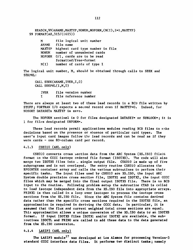
112
READ(M,99)ANAME,MAXTYP,NONUM,NOFORM,(N(I),I=1,MAXTYP)99 FORMAT(A8,315/(1615))
M file logical unit number
ANAtE file nameMAXTYP highest card type number in fileNONUM number of unnumbered cardsNOFORM 0/1, cards are to be read
formatted/free-formatN(I) number of cards of type I
The logical unit number, M, should be obtained through calls to SEEK andSEKPHL:
CALL SEEK(ANAME,IVER,I,0)CALL SEKPHL(I,M,0)
IVER file version numberI file reference number
There are always at least two of these lead records in a BCD file written bySTUFF; FORTRAN I/O expects a second record even if MAXTYP-0. Indeed, forNOSORT DATASETs MAXTYP is zero.
The NOFORM sentinel is 0 for files designated DATASET- or SUBLOCK-; it is1 for files designated UNFORM=.
These lead records permit applications modules reading BCD files to makedecisions based on the presence or absence of particular card types. Theuser's input card images follow the lead records and can be read as if theywere cards - one 80-column card per record.
4.1.3 CSE010 (ANL only)
CSE010 converts cross Section data from the ARC System (XS.ISO) file36format to the CCCC isotope ordered file format (ISOTXS). The code will alsomerge two ISOTXS files into , single output file. CSEO10 is made up of fivesubprograms and is not overlayed. The entry routine CSE01O allocates theBPOINTER container array and calls the various subroutines to perform theirspecific tasks. The input files used by CSEO10 are XS.ISO, the input ARCSystem double precision cross section file, ISOTX1 and ISOTX2, the input CCCCfiles which may be merged into the final output ISOTXS file. There is no BCDinput to the routine. Following problem setup the subroutine CTAD is calledto load isotope independent data from the XS.ISO file into appropriate arrays.PRINXD is then called in a loop over isotopes to process the isotope crosssections from the XS.ISO file. Since the ARC System file contains deriveddata rather than the specific cross sections required in the ISOTXS file, anapproximation is required in deriving the CCCC data. In particular, it isassumed that the flux and current weighted total cross sections are equal.Thi3 approximation allows a unique conversion of the XS.ISO data to an ISOTXSformat. If input ISOTXS files ISOTX1 and/or ISOTX2 are available, the sub-routines ISOCTL and PRINO are called to add these data to the data generatedfrom the XS.ISO conversion.
4.1.4 LASIP3 (ANL only)
The LASIP3 module37 was developed at Los Alamos for processing Version-3
standard CCCC interface data files. It performs two distinct tasks; namely

113
transforming free-field format, BCD data into well-defined binary files andproviding for printing and punching data in the binary files.
LASIP3 is impleme ted in the modular environment on the IBM 370/195at Argonne to provide auxiliary input processing capabilities of interest toa limited number of DIF3D users. It is not implemented in the NESC versionsof DIF3D detailed in Chapter 5.
LASIP3 was modified to incorporate the dynamic storage allocationcapability provided by the BPOINTER package discussed elsewhere in thisdocument, thereby eliminating a fixed length working storage array previouslyrequired in LASIP3 (see sample input in Fig. 3.7).
4.1.5 The General Input Processor - GNIP4C
GNIP4C is an input processor that generates a number of CCCC StandardInterface Files from BCD card-image input. Figure 4.2 shows the structure ofthe code. The main driver (GNIP4C) calls on one or more of nine subprograms.
The combination of subprograms RANIPi and FGEODS reads geometry data fromA.NIP3 cards and generates a CEODST file. For the most part RANIPL reads andchecks the data, and FGEODS composes the GEODST and LABELS files. Allsubroutines in GNIP4C whose names start with "ANIP" (e.g. any of the routinesin RANIPL) read one (and occasionally two) card types. If a GEODST fileis input RANIPi and FGEODS are skipped.
The third subprogram, EGEODS, edits the GEODST file at the user's request.EGEODS contains graphics and printer output routines that generate maps ofarrays of hexagons (TRIPLT) or orthogonal geometries (ORTMAP). TRIPLT usesdata from the A.NIP3 type 15 and 30 cards, and so GNIP4C is not able togenerate hexagonal array maps when the geometry is input via a GEODST file.ORTMAP generates its maps from data in the GEODST file. There is coding inthe subroutines associated with TRIPLT and ORTMAP to generate computergraphics maps via standard CALCOMP or DISPLA calls. This coding is commentedout in the NESC versions of the code, but it is not difficult to reactivate.
RANIP2 and FADENS read A.NIP3 data and write the number density files(NDXSRF and ZNATDN). Number density edits are produced as the input data areprocessed from A.NIP3 into GEODST, and so it is not possible for GNIP4C toedit atom densities when they are input to the code in the ZNATDN file.RANIP2 and FADENS are skipped entirely if NDXSRF and ZNATDN already exist.
BCDXST reads the formatted version of the ISOTXS file from a NOSORTDATASET named A.ISO. This is the only direct means by which the user caninput cross sections to the code on cards. BCDXST converts the formatted, BCDform into the binary file ISOTXS. Coding exists in the subprogram to convertin a similar way a formatted version of the delayed neutron data file DLAY 6S6to a binary form, however, the delayed neutron file names have not beenincluded in the DIF3D SEEK tables. There are internal flags in BCD)ST whichtrigger edits of ISOTXS and DLAYXS; however, these flags cannot be manipulatedfrom outside the code.
The seventh subprogram, WRSORC, reads inhomogeneous source specificationsfrom A.NIP3 cards and generates and edits a FIXSRC file. WRSORC is skipped
when none of the fixed source card types (A.NIP3 19 and 40-42) appear in the
input.

114
I---ANIPO3I---ANIPO4---ANIP05---ANIP06I---ANIP07--- ANIP09-------CHEK09
I--RANIPI--I---ANIP10I---ANIPlI
I I---ANIP12I I --- ANIP15I I---ANIPHXI I---ANIP34
I I---GETHGTI I---GETMSH----I--CMESH
I---GETREG I--FMESHGNIP4C-----FGEODS---I---GETBUC
ANIPOI I LOCHEX I---GETBCANIP02 I I---GETMR----I--RCMESHANIP14 I I VOLREG I--TRIGOMGETZON I I---REDMSHGETSZN ICPYLBG I I---MAKMSH
I--EGEODS---I---PRGEOD------PRNTIXI I---MPGED------MSHMAPI I---ANIP43 I--HEXPCII I---TRIPLT------HEXPIC----I--HEXPC4I I HEXPC2 I--HEXPC5I I HEXPC3 ;--HEXPC6
ROUTINES I I I--HEXPC7RI ----- I IREED I ---ORThAP-------ORTPC1----I--ORTPC3
ORTPC2 I--ORTPC4ORTPC6 1--ORTPC5
I I---ANIP13I I---GETMAT1--RANIP2---I---GETISOI I---ANIP39
I---GETSET
I--VALU2DI---SORT13---I--SET2D
I--FADENS---I---SORT14 I--INDEXI I---WNDXSR I--EDTMAT
-- BCDXST---I---RWISOT I--RWDY1I---RWDELY---I--RWDY2
I I---ANIP19I I---ANIP40I I---ANIP41 I--SORLABI I---ANIP42 I--SORMSHI--WRSORC--I---SORDAT---I--SORNZN
II- - S O R D I F
I I I--ADSlI ---ADS------l--ADS2
I I I--ADS3
D3I --WRSO---WRS----IWRSI
I I---EDSORC I--WRS2
I--ANIP21--- ANIP22
I---SRCH4DI I --- ANIP24-- WRSRCH-- --- SRCH3D
I---ANIP25I---SRCH6D
I I---ANIP26I I---EDSRCH
I --ANIP44I--IRRODS---I---SORROD
I---MAKRODI ---WRTROD---BDTPOD
ERROR BPOINTERFLTSET INTSETSQUEZE SRLABLINES SEEKTIMER FEQUATFFORM SPACECRED
COMMON BLOCKS
ARRAY BCDFLTIOPUT ISIZESPTITLE BCDINT
Fig. 4.2. Subroutine Map for the GNIP4C Code Block
UTILITY A
IEQUAT F

115
WRSRCH reads specifications for the criticality search option and writes
and edits the SEARCH file. WRSRCH is skipped when none of the search card
types (A.NIP3 21-26) appear in the input.
WRRODS processes the input for the control rod model and it is skippedwhen the A.NIP3 type 44 cards are absent.
4.1.6 Cross Section Homogenization - HMG4C
HMG4C is a cross section processor which generates the macroscopic
cross section file COMPXS based on the data contained in the CCCC filesISOTXS, NDXSRF, ZNATDN, and DLAYXS. In generating the macroscopic data, it is
assumed that there is a one-to-one correspondence between compositions andzones. Thus, for example, the fifth composition on the completed COMPXS filecorresponds to the data for zone number five on the two CCCC files NDXSRFand ZNATDN. The code accepts the CCCC files in their full generality withthe single exception that an isotope or file-wide CHI matrix is not permitted.
The data management strategy used by the code is rather straightforward.
After reading and storing the data obtained from the ZNATDN and NDXSRF files,and the isotope independent data of ISOTXS and DLAYXS, the code attemptsto hold all of the fourteen different types of macroscopic array data inthe remaining container space. If this is possible then a single pass ismade through the ISOTXS file and the contribution of each relevant isotope isadded to each macroscopic cross section of each composition. If all themacroscopic arrays will not fit in the available core, the code determines themaximum number of compositions which can be homogenized in a single pass. Asmany passes are then made as required to completely process the data. Theresults of each pass are written on a scratch file (SCRO01) for temporarystorage before being rewritten to the COMPXS file.
The three CCCC files ISOTXS, NDXSRF, and ZNATDN are always required
input to HMG4C and hence must be declared under a BLOCK=OLD statement in the
input data or generated from input BCD data by the code block GNIP4C. Thefile DLAYXS is optional but must be included under BLOCK=OLD if delayedneutron data are required. Additionally, the user may specify the BPOINTER
container size, the method by which the composition fission spectra are to be
computed, and various edit options on the BCD dataset A.HMG4C.
Figure 4.3 shows the structure of the code. The subroutines of HMG4C
may be divided into four separate functional units of code each of which maybe linked to form a separate overlay. The first overlay, OVL1, reads all of
the input data except for the microscopic cross sections. The second overlay,OVL2, computes the homogenized cross sections in the form of fourteen macro-
scopic arrays which are the working storage units of the code block. In
the third overlay, OVL3, the COMPXS data set is written from the data containedin the fourteen working arrays. The fourth overlay, OVL4, is essentiallyindependent of the preceding three and is used to edit a COMPXS file. HMG4C
may be used for the express purpose of editing a user input COMPXS file, in
which case only the fourth overlay is executed.
4.1.7 MODCXS
MODCXS is an input processor that modifies an input macroscopic cross
section file, COMPXS, to account for user specified directional diffusion
coefficients and/or energy conversion factors. A COMPXS file generated by the
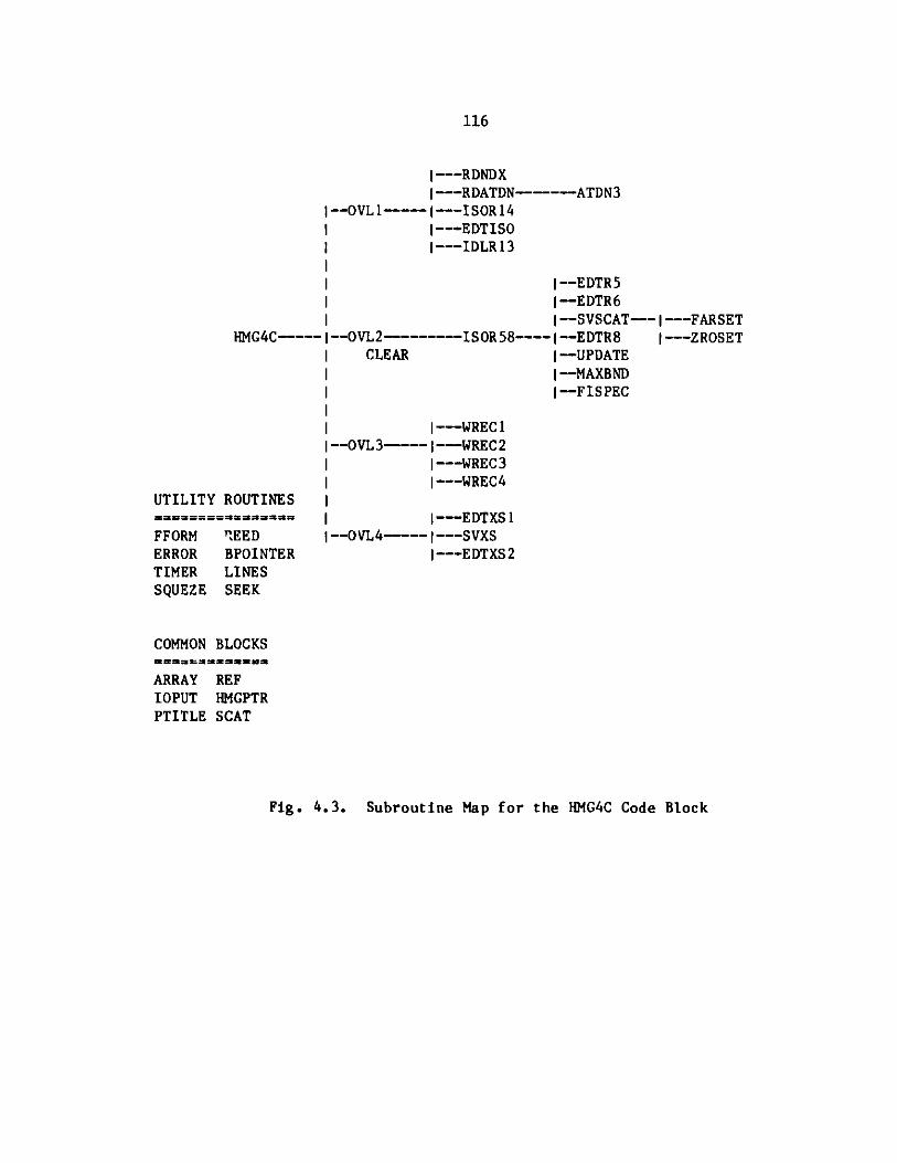
116
I---RDNDXI---RDATDN-----ATDN3
--OVL1----I---ISOR14
I I --- EDTISOI---IDLR13
I--EDTR5I--EDTR6I--SVSCAT---I---FARSET
HMG4C---- I--OVL2-------ISOR58---- I -- EDTR8 I---ZROSETI CLEAR I--UPDATE
I I -- MAXBNDI 1--FISPEC
I ---WRECII--OVL3----I---WREC2I I---WREC3
I I---WREC4
I I---EDTXS1
l--0vL4-------SVXS1---EDTXS2
UTILITY ROUTINESs==============
REEDBPOINTERLINESSEEK
COMMON BLOCKS-= ==== ======
REFHMGPTRSCAT
Fig. 4.3. Subroutine Map for the HMG4C Code Block
FFORMERRORTIMERSQUEZE
ARRAYIOPUTPTITLE

117
code block HMG4C does not include any directional diffusion coefficientcapability. Furthermore, the fission and capture energy conversion factors arederived directly from the data available on the input ISOTXS cross sectionfile. User input to override these data may be specified and the code blockMODCXS processes these data.
The code block MODCXS is made up of five subroutines. The main driverMODCXS allocates the BPOINTER container for the code block and controls theprogram flow. The first program routine called by MODCXS is ANIP35 whichreads and validates the directional diffusion coefficient data input by theuser on the Type 35 and Type 36 cards of the A.NIP3 dataset. The subroutineANIP37 is then called to read and validate the energy conversion factordata from the Type 37 and/or Type 38 cards of A.NIP3. The subroutine DOMODSis then called to process the user input data. DOMODS reads version 1 ofthe file COMPXS and writes the file SCRO01 in the same format as the COMPXSfile after modifying the power conversion and directional diffusion coefficientfactors according to the user specifications. Finally the subroutine COPIERis called to copy the data from the file SCR001 onto the file COMPXS. Thestandard utility routines are used throughout the code block to ensure codestandards.
4.1.8 BCDINP
BCDINP creates and modifies the DIF3D control file (also called DIF3D)from default values and/or from the BCD dataset A.DIF3D. BCDINP is comprisedof three subroutines and is not overlayed. The driver subroutine BCDINP setsthe A.DIF3D default parameters for the DIF3D file. If an old DIF3D fileexists the default data is overridden by data read from the existing DIF3Dfile. If an A.DIF3D file exists, subroutine RADF3D reads A.DIF3D and updatesthe DIF3D file arrays with non-default data from A.DIF3D. Upon successfulvalidation of the DIF3D file arrays by subroutine PDIF3D, BCDINP writes theinterface file DIF3D.
4.1.9 SRCH4C
The SRCH4C module controls the criticality search iterative process byadjusting certain parametric vectors in order to achieve a desired value ofk-effective. Search control information including the three most relevantsearch pass parameter estimates are maintained by SRCH4C on the CCCC interfacefile SEARCH (Appendix C.7). The interface files containing the parameter vec-tors appropriate for the selected search option are also modified by SRCH4C.
At the start of each search pass SRCH4C reads the SEARCH file to establishthe search control parameters. Next the header records of interface datasetsrequired for the selected search option are read and checked for data consis-tency. Subroutine GETCON performs this function in the concentration searchoption. Data management requirements for performing the interface file modi-fications in core-contained mode or with auxiliary disk storage are determinedat this time. If the DIF3D file is present the BPOINTER ECM container sizeestimate is obtained to determine the feasibility of the core-containedoption.
The most recent e.tgenvalue estimate will be read from the DIF3D file,if present, otherwise it will be taken from the RTFLUX file. Then subroutine
SRCHX is invoked to calculate the new search parameter estimate based upon

118
the previous estimates. A parabolic extrapolation method with root-brackettinguses three recent estimates to accelerate the parameter search process. Uponcompletion of the two initial search passes with initial parameter estimates,one linearly extrapolated estimate is employed before the parabolic procedureis invoked. The search parameter is permitted to exceed its user specifiedrange only once during the estimation algorithm. Subsequent occurences leadto problem termination.
Upon return from SRCHX the search history array is updated and theSEARCH file is rewritten. If the search parameter has not yet convergedthe subroutine which modifies the search quantity interface files is called.Subroutine DMDCON modifies the subzone volume fractions on the NDXSRF filefor the concentration search option. Upon successful modification of NDXSRF,DMDCON turns off the COMPXS existence sentinel so that upon return fromSRCH4C, subroutine D3DRIV will invoke HMG4C and MODCXS to obtain updatedmacroscopic cross sections.
SRCH4C has several features which exploit the time remaining feature ofsome systems and which exploit the DIF3D file if it is present. Consequently,the search is gracefully terminated if time limit is imminent. Abnormaltermination of the DIF3D neutronics module is detected from the restart fileDIF3D thereby causing SRCH4C to end gracefully and permitting a subsequentrestart at the current search extrapolation cycle and/or at the next DIF3Douter iteration.
4.1.10 DIF3D
The DIF3D module performs the neutron flux and criticality calculations.Figure 4.4 illustrates the structure of the DIF3D module. Names preceded byasterisks in Fig. 4.4 are relevant only to the nodal solution option describedin Ref. 5. They will not be discussed here. The four primary overlays calledby DIF3D (BININP, SSINIT, SSTATE and DSSTOU) share COMMON blocks and BPOINTERFCM and ECM container arrays. Logic sentinels and problem specifications datareside in the /CONTRL/ and /SPECS/ COMMON blocks, respectively. Definitionsfor the elements of the COMMON blocks are located in subroutine BLOCKS whichis included with the DIF3D source listing.
In stand-alone mode, the three-level overlay structure permitted by theCDC Overlay feature is retained by adding the DIF3D subroutine (and requiredutility subprograms) to the driver module D3DRIV. The different callingsequences required for the execution of DIF3D in a variety of computer systemsin modular or standalone mode are unified via the subroutines LINKRO, LINKR1and LINKR2. The suffixes 0,1 or 2 denote the (0,0)-, primary- and secondary-level overlay calls, respectively.
The module driver subroutine DIF3D initializes TIMER and then callssubroutine START which performs the following initialization functions:
1. Zeroes COMMON blocks ;
2. Sets the machine dependent word length parameter LDW (-1 or -2);
3. Sets I/O mode parameters
4. Initializes units for BCD input and output files;

119
--START
DIF3D-----I--BININP---LINKR1ILINKR2AREASVOLUMEGETBNDREVRSEWDIF3D
i
I
i-i,
i
I,
I'I'
I'
-- RDIF3D-- RLABEL--RSEARC--RCMPXS-------ADSCTM
--RGEODS----J--FORMSH1-*FORMCM
--RRTFLX-*RNHFLX--RFIXSR
--FDINIT----1--SSCORE
1--SSDISK
UTILITIES
DEFICF BLKGETPURGCF BLKPUTOPENCF OPENDFCLOSCF CLOSDFSTATCF DOPCFEQUAT IEQUATFLTSET INTSETIN2LIT LINESLINK TIMERERROR OPENDSSEEK REEDCRED DREDPCRED PNTGETPOINTER
COMMON BLOCKS
ARRAY SPECSCONTRL IOPUTIOCOM IOCOMCVERNUM IOCOMDDEBUG EDITDMBALBUF PTITLE
*NHCNTL *NHSFCM*NHIOPC *NHIOCM*NHIOPD
1--SSINIT----I EDITCR
--SSTATE----I OSWEEPI PSWEEPI TSWEEPI ROW SRCI TRISRCI SORINV
I SCTSRCI TOTSRC
I FISSRCI ZEROBAI OUT EDOI OUTEDTI CHEBE
I DACOSHI FILCPY
I--ZMINIT-- I--INEDITI I--FORMMZ-------REGMAP
'I I-*NHGEOMI I-*HEXMAP-----*GETIJ
I I-*NHZMAP-*NHINIT-----*NIPNTI I-*NHCCPTI I-*NHINED
I I-*NHCOREI I-*NHDISK
I--XSINIT----I--XSGET1-----XSEDIT
I--XSGET2
I--DXSREV----I--XSREVI I-*NHSIGA
I--DFDCAL----I--ORTFDCI I--TRIFDC
I |--ORPESI----ORPINII--DOR PES----I--OR PES2-------OR PIN2I I--RFLXINI I--FSRCINI 1--INNERII--DOUTR1---OUTER1---I--CHEBY1
S--SCTSD2I I--TOTSD2I--DOUTR2------OUTEP.2--- I--If 'ER2
I--FISSD2I--CHEBY2
RBOSOR (CRAY-1 only)RBOSRC (CRAY-1 only)
Fig. 4.4. Subroutine Map for the DIF3D Code Block

120
-*NHCC2D
I 1 -*NHCC3D1 I-*DNHCCC----I-*NHTVLC
I I I-*NHINNR
I I I -*FXREADI I-*DNHSTT----I-*FXINIT
SI I-*FXINIT
1-* UT R----I*ACCL3DS I I t-*LEAK3D
I II I-*UTR2-----*SRCFISI I I I-*SRCSCT
I III I I 1-*SRCHEX
I I I I-*PCHEX---*NHSST-----I-*DNHIUT----*OUTR3----*SRCZ1I *NHOEDO I I-*SRCZ2I *INVERT I I I-*PCZ----I *NHXSEC I
I I I -*FLXHEXII-*UTR4-----I-*FLXZ
I 1 -*FSUPDT
I I I -*CMMTR X
I I I -*CMSOLVII-*UTR5----*FSERRN
I I-*CONVCK
I I I*NHEDDM------*CPYFIL
I I -*DNHFIN---- I-*NHVOLI -*FXSHAP
I
---- *PCHEXB
------*PCZB
----I*BKRING-*AXLEAK
I--FORMMR1--BKLWGTI I--ORTSRF
-- DSSTOI---- -- SSTOU1--- -"T R~iSRF
-- WPOWER
-- POWINT----I--RPWADD1--APWADD
-- DSSTOU---TWODPRTWODTBBREDDSEQUASCALPKWPKEDT
*NHSHAP*NHPEAK*NHPKED
1--EDCOREI I--WFLUXII I-*WNHFLXI--DSSTO2-----"-SSTOU2---- I--RPSADDI II--ORTBAL
I (--TRIBALI I-*HEXBAL
I I--RBLFIS|I--BALINT---I--RBLMED
SI I--RBLADDI--DSSTO3----I 1--ABLADD
ADDVEC IDIVVEC I--FLXINT------APSADD
I--FLXRZ-------WRZFLX
Fig. 4.4. Subroutine Map for the DIF3D Code Block (cont'd)

121
5. Reads BPOINTER container size data from the binary interface fileDIF3D and allocates the container space.
Upon return from START, and prior to invoking the primary modules, DIF3Dinitializes the random access dataset utility routine DOPC.
The binary file input processor overlay driver, BININP, reads the speci-fication records from the DIF3D input interface files listed in Table 4.2(Section 4.2). The data is checked for consistency and entered into thepertinent COMMON block variables.
Using the data obtained in the BININP overlay, the SSINIT overlay callsSSCORE to determine the storage requirements for the DIF3D data manangementoptions. From these options SSCORE chooses the option that maximizes theusage of the available BPOINTER container space.
Upon completion of the data management edits in SSCORE, SSDISK is calledto establish (via DOPC) the random access disk file group assignments requiredin the multilevel data management strategy. On CDC systems an auxiliary ECMcontainer (see XCM discussion in Section 4.3.5.2) is allocated for storing thetable of pointers that index the random access file records.
The problem input data and geometry description are edited by subroutine
INEDIT. During the process of forming the zone map array, FORMMZ optionallycalls subroutine REGMAP to edit the region and/or zone to mesh intervalmaps. If the zone map array cannot be ECM-contained in concurrent inneriteration problems, it is written to the random access scratch file ZONMAP.
XSGET1 reorders the group within composition (or zone) cross sectiondata from the COMPXS interface file so that data is ordered by zone withincross section type for a given energy group. During this reordering process,XSGETL computes directional diffusion coefficients and calls XSEDIT to editthe macroscopic cross sections. If the reordering process cannot be core-contained, cross sections are written by composition to the auxiliary fileSCRO01 by subroutine XSGETI. Subroutine XSGET2 performs the necessary numberof read passes across SCROO to complete the reordering process. In eachpass a core-containable bandwidth of groups is processed.
The primary overlay SSTATE has five secondary overlays (DXSREV, DFDCAL,DORPES, DOUTR1 and DOJTR2). In adjoint problems, DXSREV calls XSREV whichreverses the cross section group ordering and forms the adjoint scatteringmatrix. In the event that the available container storage is insufficientto core-contain all groups, the real problem cross sections are copied toauxiliary file SCROO1. The cross section reversal process is then performedin multi-pass mode with the maximum permissible bandwidth of groups core-contained in each pass.
Overlay DFDCAL calls FDCAL which controls the finite difference coefficientcalculation by calling the appropriate subroutines ORTFDC or TRIFDC fororthogonal or triangular geometries, respectively. For data managementpurposes, mesh cells for both orthogonal and triangular geometries are mappedby mesh plane onto a rectangular array. In certain triangular geometryproblems and in problems with black absorber composition assignments some of

122
the mesh cells are excluded from the problem solution domain. In triangulargeometry two arrays IS(j) and IE(j),j=1,2,...,J define the lower and upperindex limits of the active mesh cells on line j. Mesh positions outside theselimits are logically excluded from all calculations. Mesh cells which must beexcluded from the problem domain, but which lie within the limits of theactive mesh cells are effectively excluded from the problem domain by assigningthe value zero to transverse direction coupling coefficients. Thus, computa-tions proceed in an identical fashion for both active and excluded mesh cellswith no additional logic overhead.
The DORPES overlay calls ORPES1 or ORPES2 to compute the optimum successiveline overrelaxation factors for the inner (within group flux) iteration.Because of significant differences in data management strategy, dual sets ofsubroutines, differentiated by the suffixes I or 2, are employed. The firstset applies to strategies in which at least one energy groups worth of data isECM-contained; the second set applies to the concurrent inner iterationstrategy which requires a minimum of three planes worth of data to be ECM-contained. Subroutines ORPIN1 and ORPIN2 control the Gauss-Seidel inneriterations employed to estimate the optimum factors Wg. These routineswere cloned from the routines INNERL and INNER2 which perform the inner itera-tion sweeps during the outer iteration.
DORPES also calls RFLXIN and FSRCIN to read the real (adjoint) fluxfile RTFLUX (ATFLUX) and the fixed distributed inhomogeneous source fileFIXSRC. If the the flux file does not exist, RFLXIN creates a flat flux guessof unity. In near-critical inhomogeneous source problems, an initial fluxguess of zero is optionally generated. lesh cells are initialized to zerowhen they are within the active portion of the rectangular data structure ofthe mesh plane arrays, but they are not part of the problem domain.
Overlay DOUTR1 calls subroutine OUTER1 which controls the outer (fissionsource) iterations and in thermal problems the upscatter iterations whichare required to solve the multidimensional neutron diffusion equation whenat least one energy group of flux, finite difference coefficients and crosssection files can be ECM-contained. OUTERI calls subroutines FISSRC, SCTSRCand TOTSRC which compute the fission, scattering and leakage sources and addthem to the fixed source, if present. It also calls subroutines INNER1 andCHEBYL which perform the inner iterations (within group flux calculations) andextrapolate the resulting fission source, respectively.
One of two data management strategies for calculating the scatteringsource are chosen based on whether or not the scattering band of fluxes canbe ECM-contained. When the latter is true, the scattering source calculationis performed by double buffering the scatter band of fluxes through memoryfrom disk one group at a time. When the former is true, the buffer for thescatter band of fluxes is treated in a circular manner. Upon filling thecircular buffer, unneeded flux values are displaced, if necessary, byappropriate fluxes as the group index advances during each outer iteration.
Following each completed outer iteration pass, the average time requiredper outer iteration is computed to determine the feasibility of performingthe next outer iteration and completing the editting wrapup in the remainingtime indicated by the TIMER subroutine.

123
Overlay DOUTR2 calls subroutine OUTER2 which controls the outer iterationsfor the concurrent inner iteration option. The source computation routines(FISSRC, SCTSRC and TOTSRC) are called from the intermediate driver routinesFISSD2, SCTSD2, and TOTSD2, respectively. The initial fission source iscomputed by IFISD2. Subroutines INNER2 and CHEBY2 perform the inner iterationsand extrapolate the resulting fission source, respectively.
The scattering source calculation accesses blocks of flux planes from theenergy groups in the scattering band of fluxes pertinent to the current energygroup. The I/O requirements of such calculations are appropriately treated bythe random access I/O features available on the IBM and CDC versions of DIF3D.
The DSSTOU overlay calls three secondary overlays (DSSTO1, DSST02 andDSSTO3) that perform the optional region, area and mesh cell flux integraledits. Two general purpose subroutines (TWODPR and TWODTB) are employed toperform mesh cell tabulations and region (and area) tabulations, respectively.TWODTB also writes a copy of the edified tables to the D3EDIT interface file.
The DSSTO1 overlay initializes the editting overlays by establishingthe edit sentinels in COMMON block EDITDM and then calls FORMMR to generatethe region-to-mesh-interval map array and BKLWGT to compute region-dependenttransverse-direction weight factors for the volume and flux integrals.Subroutine SSTOU1 performs the following tasks:
1. Obtains the power normalization factor in real criticality(homogeneous) problems;
2. Edits and/or writes the PWDINT power density interface file;
3. Edits total power in real fixed source problems;
4. Controls the surface power and flux calculations in the ORTSRF andTRISRF subroutines;
5. Writes via WPKEDT the peak (surface) power interface file, PKEDIT,for the post processing edit module SUMMARY;
6. Edits maximum power density and corresponding mesh cell indices;
7. Creates the mesh cell power densities for subsequent use by thePOWINT, RPWADD and'APWADD subroutines which compute and edit theregion and area dependent power density integrals.
The DSSTO2 overlay establishes via subroutine EDCORE the block sizesfor the requested region and area integrals. Then subroutine SSTOU2 is calledto write the appropriate flux interface files RTFLUX or ATFLUX. In realhomogeneous problems the flux is power-normalized prior to editing or writing.The group-integrated fluxes by mesh cell are optionally edited here,also.If region or zone integral edits are requested, RPSADD is called to computethe region flux integrals. ORTBAL and TRIBAL are called to compute regionleakage components in orthogonal or triangular geometries. Overhead isminimized by requiring only one I/O pass over the unnormalized flux data.Depending opon the requested edit options one or more sweeps across theresident block of fluxes may be required. In the first sweep, fluxes are

124
power-normalized, written and optionally editted. The group-integrated fluxesby mesh cell are accumulated also. In adjoint problems an additional I/O passis required to reverse the flux group ordering for integral edits. An addi-tional NBLKR sweeps (NBLKR is the number of region blocks) over the residentblock of flux planes are made to compute the region flux integrals and theleakage component integrals for the neutron balance edits. Prior to exitingSSTOU2 the region-to-mesh-interval map is converted back to a zone-to-mesh-interval map.
The DSST03 overlay optionally calls three subroutines (BALINT, FLXINTand FLXRZ) which edit the region and area balance integrals, the region andarea flux integral totals and/or the region averaged fluxes, and the zone-averaged fluxes (e.g. the kZFLUX file), respectively.
4.1.11 SUMMARY (ANL only)
The SUMMARY module is used with DIF3D at ANL to edit summary reactionrates and isotopic masses. It is evoked whenever the A.SUMMAR data set issupplied with the input data (the single card-image "DATASET=A.SUMMAR" issufficient data to trigger a SUMMARY edit). The interface files RTFLUX,GEODST, ISOTXS, NDXSRF, ZNATDN and COMPXS must also be present (these normal-ly exist following a typical DIF3D calculation). If present, SUMMARY willalso use the LABELS, PKEDIT, and NHFLUX files.
4.1.12 UDOITL-UDOIT4
The four UDOIT modules, UDOITL - UDOIT4 are user modules placed at stra-tegic points in D3DRIV to provide the user with additional processing capabi-lity during the calculational sequence (see Fig. 1.1). This feature of DIF3Dis particularly useful in modular systems where the dummy UDOIT modules maybe easily pre-empted by user UDOIT modules located in an automatic-call li-brary that may be processed via the ARCSPO21 procedure parameter PRELIB='name'.The user merely creates a self-contained load module which communicates withthe DIF3D system via the appropriate interface files and thereby tailorsDIF3D processing capabilities to suit his needs. This feature may beexploited in stand-alone implementations by relinking DIF3D with dummy useroverlays appropriately replaced. Four interface file names (three binaryfiles UDOIT versions 1, 2 and 3 and one BCD file A.UDOIT) are reserved in theSEEK file table for UDOIT applications.
4.2 Data Set Classification and Use by Code Block
Table 4.1 lists all of the data sets used by the code blocks in DIF3D andclassifies them into one of five different categories:
BCD: Formatted, sequential access input and output, including
standard system data sets (see definitions in Appendix B);
CDB: Code-dependent (including ARC system) binary (unformattedsequential access) interface data sets (see definitions inAppendix D);
CCCC: CCCC binary interface data sets (see definitions in Appendix C);
DOPC: Unformatted random access scratch data sets;
SCR: Sequential access scratch data sets.

125
TABLE 4.1. Data Set Classification and Description
FileReference File File FileNumber Name Type Description
45689
1011121314151617181920222324252627282930313233343536373839
41-5661,6266-7576-78
80
DSPLASC1
DSPLAFNT
A.DIF3DA.NIP3A.HMG4C
A.LASIP3A.ISOBCDSOB
A . SUMMARDIF3DCOMPXSLABELSD3EDITNHFLUXNAFLUXPKEDITGEODSTISOTXSNDXSRFZNATDNRTFLUXATFLUXFIXSRCRZFLUXPWDINTISNTXSISOTX1ISOTX2SNCONSSEARCHRNDMnnXSISO
SCRO01-10UDOITAUDOIT
SCRBCDBCDCDBBCDBCDBCDBCDBCDBCDBCDBCDBCDCDBCDBCDBCDBCDBCDBCDB
CCCCCCCCCCCCCCCCCCCCCCCCCCCCCCCCCCCCCCCCCCCCCCCCCCccCCCCDOPCCDBSCRCDBBCD
graphics scratch fileinput data for SCAN moduleoutput data all modulesgraphics font datainput data spool from SCANauxiliary output all modulesDIF3D controlGNIP4C controlHMG4C controlLASIP3 controlBCD ISOTXSBCD LASIP3 outputSTVMNARY controlDIF3D controlmacroscopic cross sectionslabels, half-heightstabular edits spoolnodal restart (real)nodal restart (adjoint)peak power/flux interfacegeometry descriptionmicroscopic cross sectionsnuclide/zone referencezone nuclide atom densitiesreal fluxadjoint fluxfixed sourcezone flux averagespower densityaux. ISOTXS slotaux. ISOTXS slotaux. ISOTXS slotSn constants (transport)SRCH4C controlrandom access scratch files (Table 4.3)micro. cross section files 1 and 2scratch filesUDOIT versions 1-3UDOIT module input
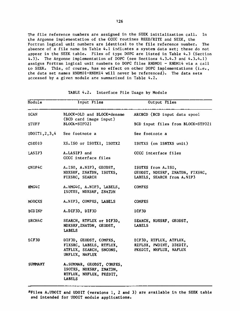
126
The file reference numbers are assigned in the SEEK initialization call. Inthe Argonne implementation of the CCCC routines REED/RITE and SEEK, theFortran logical unit numbers are identical to the file reference number. Theabsence of a file name in Table 4.1 indicates a system data set; these do notappear in the SEEK table. Files of type DOPC are listed in Table 4.3 (Section4.3). The Argonne implementation of DOPC (see Sections 4.3.4.3 and 4.3.4.1)assigns Fortran logical unit numbers to DOPC files RNDMO1 - RNDM14 via a callto SEEK. This, of course, has no effect on other DOPC implementations (i.e.,the data set names RNDMO1-RNDM14 will never be referenced). The data setsaccessed by a given module are summarized in Table 4.2.
TABLE 4.2. Interface File Usage by Module
Module Input Files Output Files
BLOCK=OLD and BLOCK=dsname(BCD card image input)BLOCK=STPO21
ARCBCD (BCD input data spool
BCD input files from BLOCK=STPO21
UDOIT1,2,3,4 See footnote a See footnote a
XS.ISO or ISOTX1, ISOTX2
A.LASIP3 andCCCC interface files
A.ISO, A.NIP3, GEODST,NDXSRF, ZNATDN, ISOTXS,FIXSRC, SEARCH
A.HMG4C, A.NIP3, LABELS,ISOTXS, NDXSRF, ZNATDN
A.NIP3, COMPXS, LABELS
A.DIF3D, DIF3D
SEARCH, RTFLUX or DIF3D,NDXSRF,ZNATDN, GEODST,LABELS
DIF3D, GEODST, COMPXS,FIXSRC, LABELS, RTFLUX,ATFLUX, SEARCH, SNCONS,UHFLUX, NAFLUX
A.SUMMAR, GEODST, COMPXS,ISOTXS, NDXSRF, ZNATDN,RTFLUX, NHFLUX, PKEDIT,LABELS
ISOTXS (on ISNTXS unit)
CCCC interface files
ISOTXS from A.ISO,GEODST, NDXSRF, ZNATDN, FIXSRC,LABELS, SEARCH from A.NIP3
COMPXS
COMPXS
DIF3D
SEARCH,LABELS
NDXSRF, GEODST,
DIF3D, RTFLUX, ATFLUX,RZFLUX, PWDINT, D3EDIT,PKEDIT, NHFLUX, NAFLUX
SCAN
STUFF
CSE010
LASIP3
GNIP4C
HMG4C
MODCXS
BCDINP
SRCH4C
DIF3D
SUMMARY
aFiles A.UDOIT and UDOIT (versions 1, 2 and 3) are available in the SEEK tableand intended for UDOIT module applications.

127
1 4.3 Data Management Considerations
A multilevel transfer approach that unifies the treatment of one- ortwo-level storage hierarchy machines is adopted in DIF3D. The implementationemploys a set of high level subroutines to perform the data management tasks.These subroutines in turn exclusively employ the standardized utility sub-routine calling sequences defined by the CCCC6, thereby providing a highlyexportable code system that has been tailored to utilize machine-dependentmultilevel and random access I/O methods.
4.3.1 Data Management Concepts
The following terminology will be used in the ensuing discussion (seeRef. 6 for more detailed definitions):
1. Extended Core Memory (ECM): That (physically separate or logicallydesignated) portion of a computing system containing storage locationswhich serve as a buffer for random access data.
2. ECM File: A named array allocated within the BPOINTER ECM container.This array provides a buffer area for one or more blocks of randomaccess file data. Associated with an ECM file is a block structureidentical to the random access files it services.
3. Fast Core Memory (FCM): That portion of a computing system whichcontains storage for both data and instructions, which is directlycoupled to the computations portion of the system, and which isdirectly coupled to ECM. FCM may be the entire central memory or itmay be that portion of central memory remaining after an ECM portionis designated.
4. Random Access Data: Data which can be transferred between FCM andECM in out-of-sequence strings.
5. String: A subportion of a random access file block. Data transfersbeween FCM and ECM are string transfers.
6. Random Access File: (Also called Direct Access File). A namedcollection of data which is stored on a peripheral storage device.The file data are arranged in blocks which can be transferred betweenECM and peripheral storage randomly, i.e. out of sequence.
7. Logical File: A random access file. The identity of a logical filein DIF3D is established by an integer variable, the (logical) filereference (or unit) number.
8. Logical Record: A basic unit of information used in the definitionof a logical file; all records in a logical file are the same length.
9. Logical Record Group: A logical collection of records. Each recordgroup in a file has the same number of records (e.g. a group andspace-dependent flux file has each flux plane of each group as arecord and all flux planes (records) in a particular energy group asa logical record group).

128
10. Block: A collection of logical records in a record group of arandom access file. Each block consists of an equal number ofrecords (N) except for the last block in a record group which mayhave M<N records. The block length is always less than or equal tothe record group length. Data transfers between disk and ECM areblock transfers.
11. Disk: A generic name for a peripheral storage device used forstoring random access files.
12. Physical Unit: An identifiable subpart of a disk. One of morephysical units comprise a disk.
13. File-Group: A collection of one or more random access files. Thefile-group collection is assigned to a single physical unit.
4.3.2 Multilevel Data Management Strategy
The standardized method6 of multilevel data management employs thedata transfer paths illustrated in Fig. 4.5. Each random access file iscomposed of one or more record groups and resides on a physical unit. Whenneeded, data is transferred (via DRED and DRIT) in blocks of records betweendisk and ECM, and then strings of data are transferred (via CRED and CRIT)between ECM and FCM. When the ECM and FCM BPOINTER containers both reside in
the same memory level, data from ECM is used directly, thereby avoidingredundant memory allocation and data transfer. Most of the bookkeepingassociated with this data management approach is consolidated and eliminatedby the high level data management routines described in Section 4.3.4.
The principal goal of the DIF3D data management strategy is to minimize
the use of costly random access I/O transfers by optimizing the use of theavailable ECM container (ECM size is specified on the type 02 card of A.DIF3D).As mentioned in Section 3.9.1 two principal strategy options, the one-group-contained option and the concurrent inner iteration option, are availableto achieve this goal. The latter option performs one or more I/O sweepsacross the data required in the within-group (inner) iteration for a givenouter iteration because the data for all planes in the current group are notsimultaneously contained in ECM. The former option requires exactly one I/Opass across the data. As ECM size is increased beyond the one-group-containedthreshold an attempt is made to contain additional data, namely, a scatteringband of fluxes or the entire flux file, and/or cross sections, finite-differ-ence coefficients and fission sources. Ultimately, a third option, all filesECM-contained, is possible at which point no DOPC files are required except forthe DOPC file FSRC in inhomogeneous source problem.
The principal data structures in the strategy options are the ECM filesthrough which all data are buffered for the (up to 14) random access disk fileslisted in Table 4.3. The block structure of an ECM file is identical to thestructure of the random access disk files that it will service. However,only a subset of the total number of blocks in a DOPC file is typicallyallocated to an ECM file in most strategy options.
Data is transferred between the random access scratch files in Table 4.3
and the corresponding ECM files listed in Table 4.4 using the DIF3D datamanagement routines BLKGET and BLKPUT which in turn call the standardized CCCC6

ECM"DRED
DRIT BUFFERS
FAST CORE
ECM
BUFFERS
MEMORY (FCM)
CRED
CRIT
FCM
ARRAYS,
BUFFERS
EXTENDED COREMEMORY (ECM)
Fig. 4.5. Multilevel Data Transfer Paths
129
FCM
ARRAYS
ONE
LEVEL
MACHINE
DISK
BLOCKDRED
DRIT
TWO
LEVEL
MACHINE
FCM
BLOCK

130
TABLE 4.3. Random Access File Descriptions
DOPC File SEEK SEEK ARCSPO21Reference Group Reference Table File
Number Number Number File Name Name
1 2 41 RNDMO1 PSIOLD2 3 42 RNDMO2 PSINEW3 5 43 RNDMO3 PSIUP4 1 45 RNDMO4 FDCOEF5 2 46 RNDM05 FRNOLD6 3 47 RNDM06 FRNNEW7 4 48 RNDMO7 FRNM18 5 49 RNDMO8 FRNM29 4 51 RNDMO9 SRCNEW10 1 52 RNDM10 ZONMAP11 6 53 RNDMl1 CXSECT12 4 54 RNDM12 FSRC13 2 55 RNDM13 PSIGO14 3 56 RNDM14 PSIGN
TABLE 4.4. Correspondence Between ECM and Disk Files
ECM DiskFile Name File Name File Contents
ZONMAP ZONMAP Zone to fine mesh mapCXSECT CXSECT Macroscopic cross sectionsZONMPC* -- Zone to coarse mesh cell mapPSINEW PSIOLD,PSINEW Flux iterate (all groups)BPSI* j PSIG0**,PSIGN** Flux iterate (current group)FDCOEF FDCOEF Finite difference coefficientsSRCNEW SRCNEW** Group total sourceFRBUFS FRNMI,FRNM2 Fission source iteratesFRNM1**,2**f IFRNOLD**,FRNNEW**CXSADJ CXSECT Adjoint ordered cross sectionsVOLUME -- Unit height mesh cell volumes in X-Y planeAREATC* -- Cross sectional area for any X-Y planeAREAFC* -- Cross sectional area for any X-Z planeAREALC* -- Cross sectional area for any Y-Z plane
REGMPC -- Region to coarse mesh cell mapPOWERF PSIGO**,PSICN** Power density by mesh cellPEAKFL FRNNEW** Peak total flux by mesh cellPEAKFF FRNOLD** Peak fast flux by mesh cellPEAKPW SRCNEW** Peak power density by mesh cellSRFBUF SCROO1,2 Surface fluxes by mesh cellRPWINT SCROO1 Region power integralsAPWINT SCRO02 Area power integralsTOTPSI PSIGO**,PSIGN** Total flux by mesh cellRPSINT SCROO1 Region flux integralsAPSINT -- Area flux integralsRBLBUF SCR006,3,4 Region balance (leakage) integralsRBLINT SCR003,1,2 Region balance integralsRBLTNT SCR003,1,2 Region balance integral totalsABLINT SCR004,5 Area balance integralsABLTNT SCR004,5 Area balance integral totalsZPSINT SCRO05 Zone-averaged flux integrals
* Temporary ECH files
* CIIS option only

131
routines DRED and DRIT. ECM files are opened (via calls to OPENCF) with thenumber of blocks required by the current data management option.
Except for ZONMAP and CXSECT which are defined in SSINIT, all ECM filesin the upper half of Table 4.4 are defined (via DEFICF) in subroutine SSTATE.ECM files in the lower half of Table 4.4 are defined in one of the three editoverlay drivers (DSST01, DSST02 or DSST03). The ECM files are not opened(i.e. ECM container space is not suballocated to a particular ECM file)until an OPENCF call is issued. When an ECM file is no longer needed its ECMspace may be via a call to CLOSCF. The definitions of the DOPC files are made(via DOPC and DEFIDF) in subroutine SSDISK. The characteristics of the ECMand DOPC files are provided in the subroutine calls to DEFICF and DEFIDF andwill not be repeated here.
Several of Lhe ECM files in Table 4.4 are temporary files needed duringpreliminary stages of the DIF3D calculation (e.g. ZONMPC, CXSADJ, AREATC,AREAFC and AREALC). The temporary files use ECM space that will later bereused by the major ECM files during the outer iteration strategy.
Numerous small arrays are allocated in the FCM container. Documentation
of these arrays occurs in the source listings of the subroutines which usethem. Data transfer required for these arrays is performed by the CCCCroutines REED and RITE. An auxiliary group of arrays are allocated inFCM on two-level machines, of which the CDC 7600 is the only machine on whichwe have had operating experience. These FCM arrays provide a computationalbuffer area in which data passed from ECM may be efficiently processed,thereby avoiding the less efficient computations that result when ECM filesare directly addressed (see discussion in Section 4.3.2.3).
The auxiliary edit files in the lower half of Table 4.4 are opened at
different stages in the editing overlays. A number of these ECM files areregion and area integral files which have a logical record group structuresimilar to the flux files. 'Within a record group, however, blocking is simplybased on the available ECM container space; a natural block size (such as amesh plane in files of mesh cell data) does not exist. Because of the specialnature of these region and area files and their relatively limited resourceutilization, the BLKGET and BLKPUT routines are not used to transfer databetween disk and ECM. Instead we use the sequential access routines REED andRITE to transfer data from scratch files SCROO1-SCRO06 directly to ECM fileson one-level machines. On two-level machines auxiliary FCM sub-blocks areallocated for computational efficiency (as noted in Section 4.3.2.3) and datais transferred between disk and FCM using REED and RITE. After processing a
sub-block of data pertinent sub-blocks are transferred between FCM and ECM usingCRED and CRIT. Several sub-blocks of data may then be successively saved inand reused from ECM until the next region or area block is required.
4.3.2.1 The One-Group-Contained Strategy
In this strategy each block of an ECM file contains all data for at
least one energy.group (i.e. all mesh planes in mesh cell dependent files).Therefore, each ECM file requires one block of appropriate size. During the
outer iterations the FDCOEF and BPSI files are alternately opened and closedonce each outer to permit the reuse of ECM space. When a scattering band offluxes is ECM-contained, the ECM file (PSINEW) is opened with MAXSCT+1 blocks

132
where MAXSCT is the maximum scattering bandwidth. The BPSI file is not usedin this case. The three most recent iterates of the fission source file arerequired for the Chebyshev acceleration of the outers. The two most recentiterates are held in the ECM file FRBUFS which unlike the other ECM files isnormally assigned two blocks. The oldest iterate is buffered through the ECMfile SRCNEW alternately from DOPC files FRNM1 or FRNM2 on which it had beenpreviously saved. When sufficient ECM space exists, three blocks are allo-cated to FRBUFS thereby permitting the three most recent fission source esti-mates to ECM contained.
4.3.2.2 Concurrent Inner Iteration Strategy
The concurrent inner iteration strategy (CIIS) requires that data foronly a fraction of the total number of mesh planes be ECM-contained duringthe within-group inner iterations. Consequently, three-dimensional problemswith an unlimited number of mesh planes are permitted with the number of meshcells on a plane dictated by the ECM container size.
The K planes in each energy group are partitioned into Q blocks ofplanes with block size L. An upper bound on the block size L is an inputparameter on the type 03 card of A.DIF3D. This bound represents an estimatedoptimal block length for efficient I/O performance on a particular machine.As mentioned in section 3.10.1, an attempt is made to ECM contain as manyblocks of planes of size L as is possible with the given ECM container size.
The CIIS algorithm is sketched in a FORTRAN-like notation in Fig. 4.6.
The inner iterations sweep across the mesh planes in a wave-front fashion,processing all data on a particular plane before proceeding to the next plane.As an inner iteration for one block completes, the next iteration for allpreceding blocks can be performed. U, the effective number of blocks whichcan be simultaneously contained in ECM determines the wavefront or bandwidthof inner iterations (B=UL) which can be performed in a single I/O pass overthe current group data. After the B'-th iteration has completed for all planesin a given block the write operation for the block may be initiated. Althoughthe calculations for the new flux in this block are completed, the block mustremain in ECM for the next I/O cycle because data in the last plane of theblock is required during the next cycle. During this cycle the asynchronouswrite operation is given time to complete. The number of inner iterations,Mg, for each outer iteration determines the number of I/O passes, Pg,
Pg - (Mg + B - 1) / B
required to complete the inner iterations in group g. A diagram of the I/Oand CPU activity that occurs in the ECM file PSINEW on two successive I/Ocycles c and c+1 is illustrated in Fig. 4.7.
In summary, each inner iteration pass, p-1,2,...,Pg, is comprised ofc-1,2,...,C I/O cycles. The following events occur in cycle c:
1. The asynchronous reads for block c (c<Q) are completed and reads for
block c+1 (c<Q) are initiated.
2. In the first pass (p-1) the group source for block c is calculated
and saved for for later passes.

133
Q = (K+L-1) / LB = U * LC = U+QDO 400 g = 1,NGROUP
Pg = (Mg-l)/B + 1
DO300 p = 1,Pg
B' = min( B, Mg-(p-1)*B )'initiate reads on block (1,g) data'DO 200 c = 1,C
IF (c<Q) 'finish reads on block (c,g) data'IF (c<Q) 'initiate reads on block (c+1,g) data'IF (c<Q and p=1) 'calculate block (c,g) group source'DO 100 b = 1,B'
Ks = max( 1, c*L - b - L + 1 )Ke = min( K, c*L - b )IF ( Ks<Ke ) 'perform inner iteration for planes Ks to Ke'
100 CONTINUEIF (c>U+L) 'finish write of flux block (c-U-1,g)'IF (c>U) 'initiate write of flux block (c-U,g)'IF (p=Pg and c>U) 'compute fission source for block (c-U,g)'IF (p=Pg and c>U and g=G) 'perform Chebyshev acceleration on
fission source block (c-U,g)'200 CONTINUE
'finish writes on flux block (Q,g)'300 CONTINUE400 CONTINUE
Fig. 4.6. Concurrent Inner Iteration Algorithm

134
I/O CYCLE c
INNER ITERATIONSWEEP INDICES
1 2 3 4 5 6
WRITINGFLUX- BLOCK
c-U-I
6
5 6
4 5 6
/(/4 5
1 2 3
I 2 PL ANE cL-2
SPL ANE cL- I
PLANE cL
READING
FLUX-BLOCK
c+1
I/O CYCLE c+I
INNER ITERATIONSWEEP INDICES
1 2 3 4 5 6
READINGFLUX- BLOCK
c+2
WRITINGFLUX-BLOCK
c-U
6
5 6
4 5 6
3 4 5
2 3 4
1 2 3
1 2
Fig. 4.7. Concurrent Inner IterationI/O Cycle Description (L=3, U=2)
c-U-I
c-U
BLOCKINDICES
c-I
C
c+2
c-U
c-I
c
c+Ic+I

135
3. The B' inner iterations for blocks c-U to c are performed (SeeFig. 4.7).
4. The write for flux block c-U-1 is completed and the write for blockc-U is initiated.
5. On the last pass Pg the block c-U fission source is calculated andChebyshev acceleration is applied.
The storage requirements (in units of mesh planes) for the variable sizeCIIS blocks are summarized by:
1. U+3 fluxes,
2. 4(U+2) finite difference coefficients,
3. U+2 total group sources,
4. 4+1/LDW miscellaneous data (3 fission sources, 1 flux and 1/LDW zonemap).
The constant terms in these storage requirements formulas account for auxiliaryblocks required to achieve a high degree of I/O and CPU concurrency. LDW is aword length parameter which accounts for the fact that integer array storagerequirements are half that of long words on short word machines, The procedurefor estimating the optimal ECM size for a given problem and for -terminingthe appropriate value for U is presented in Section 3.10.1.
4.3.2.3 Two-Level Machine Data Management Considerations
As mentioned earlier (Section 4.3.2) transfers between ECM files andFCM arrays use the CCCC utility routines, CRED and CRIT. This practice avoidsthe inefficiencies obtained when single data items are directly addressedat random locations in ECM. After allocating required fixed size arrays inFCM including the cross sections array for one group, the remaining plane-oriented mesh cell arrays are blocked with one or more mesh lines per blockbased on the FCM container size (specified on card 02 of A.DIF3D file).
Because of the regular nature of the mesh cell structure in the DIF3Dfinite difference option, the two-level strategy is implemented with noessential change to the solution algorithm. Loops over the J lines in a planeare replaced by an equivalent set of two loops; a loop over blocks of lines ina plane and a loop over lines within each such block. The one-level implementa-tion simply uses the special case of all J lines contained in a single block.
Prior to processing each block of lines, data from appropriate ECMfiles must be transferred to FCM (via CRED). After processing each block oflines newly calculated data must be transferred to ECM (via CRIT). Thepointers to the FCM arrays used which receive the ECM data are always passedas subroutine arguments to the routines in which the CRED and CRIT occur. Onone-level implementations these pointers are set to the appropriate locationin the directly addressable ECM file.
136
Coding which is pertinent only to the two-level data transfers (e.g.CRED and CRIT calls and associated indexing) is bracketted by C2LV commentcards4 1 which are "activated" by a preprocessor code when generating atwo-level implementation of DIF3D. When partial plane blocking is requiredin FCM, additional coding is required for initialization tasks in the next-adjacent-face periodic boundary condition option. An additional array isneeded to contain the boundary fluxes (along the lower X-boundary on planek) which are required in the transverse leakage calculations for the j=1 lineon plane k. A similar array is needed for the reverse calculation.
4.3.3 DIF3D Data Management Routines
The high level data management routines developed for DIF3D are designedto simplify the bookkeeping associated with managing the disk and ECM files in
a variety of machine environments. These routines employ the BPOINTER routines' 1
to manage ECM file allocations in the ECM container and call the CCCC routines
DOPC, DRED and DRIT to perform asynchronous, random access I/O tasks.
The DIF3D routines may be logically divided into two primary groups,those related to ECM files and those related to DOPC files. The first groupincludes DEFICF, OPENCF, CLOSCF, PURGCF, VNTGET and PCRED. They communicatewith each other via the CFTABL COMMON block in which is located data defining
the characteristics and current state of each ECM file. The second groupincludes DEFIDF, OPENDF and CLOSDF which communicate via the RNDMFL COMMONblock in which is located data defining the characteristics and currentstate of each DOPC file. The BLKGET subroutine with entry points (FINGET,BLKPUT and FINPUT) controls data transfer between DOPC files and ECM filesand therefore belongs to both groups.
The PCRED routine with entry points (ICRED, PCRIT and ICRIT) is a recent
addition to these data management routines and is employed only in the nodaloption.
4.3.3.1 DEFICF
The characteristics of each ECM file are specified to the DIF3D data
management routines by a call to DEFICF. The calling sequence for DEFICF is:
CALL DEFICF ( CFNAM, NREC, LREC, NRBLK, NRGRP, LCFN)
This call defines the characteristics of ECM file, CFNAM, which has NRECrecords of length LREC (single precision) words. There are NRBLK records ina block and NRGRP records in a record group. LCFN is the ECM file referencenumber by which this file may be addressed and is simply the index of thenext available entry in the ECM file table in COMMON block CFTABL. CallingDEFICF with CFNAM = CLEARC will initialize the CFTABL COMMON block.
Entry point DELECF deletes file CFNAM and zeroes its CFTABL entries.
Entry point CHNGCF changes the name of the ECM file having reference numberLCFN to the name CFNAM.
4.3.3.2 OPENCF
After the characteristics of an ECM file have been defined (via DEFICF),
ECM container space may be suballocated for it via a call to OPENCF:

137
CALL OPENCF( CFNAM, LCFN, NBUFS, IFTYP )
This call issues a call to the BPOINTER routine PUTB to allocate an arraynamed CFNAM. The call allocates space for NBUFS blocks where the size of ablock was given in the DEFICF call. The sentinel IFTYP signals one of twooperational modes for the ECM file. Files that require I/O transfers aredesignated with IFTYP=1. Random access files that are ECM-contained andrequire no I/O transfers are designated by IFTYP=0. Subsequent calls toBLKGET or BLKPUT will automatically ignore I/O requests for these files.Note below the effect of CLOSCF calls with action sentinel unity on IFTYP=Ofiles.
Calls to OPENCF for files that have already been opened are ignored ifeither the file is already ECM-contained or if the existing file is not ECM-contained but has sufficient space to contain the requested NBUFS blocks. Afile opened with IFTYP=1 can be changed to ECM-contained mode (IFTYP=O) bycalling OPENCF with IFTYP=O provided NBUFS is identical to the existing numberof blocks already allocated.
4.3.3.3 CLOSCF
When an ECM file is temporarily or permanently no longer needed, theCLOSCF subroutine may be used to release the buffer space. The callingsequence for CLOSCF is:
CALL CLOSCF ( LCFN, NOP )
This call releases the suballocated buffer space for the ECM file with referencenumber LCFN depending on its associated OPENCF sentinel and the action sentinelNOP. If NOP = 0 or 2, the buffer space is unconditionally released (via theBPOINTER WIPOUT command). When NOP = 0 this call also deletes (via an internalDELECF call) the ECM file from the list of files in the CFTABL common block.Calls to CLOSCF with NOP = 1 are ignored when the file is ECM-contained (i.e.opened with IFTYP = 0).
4.3.3.4 PURGCF
Following one or more calls to CLOSCF, the released ECM container storagemay be recycled for subsequent use by calling PURGCF. The calling sequencefor PURGCF is:
CALL PURGCF (LSTBUF)
PURGCF calls the BPOINTER routine PURGEB to clean up a fragmented ECM con-tainer and then refreshes the ECM pointers for all ECM files that remainopen. A pointer to the first unused ECM location is returned in LSTBUF.
4.3.3.5 BLKGET, FINGET, BLKPUT and FINPUT
All I/O requests to random access files are channeled through BLKGETand FINGET or BLKPUT and FINPUT which ultimately invoke the CCCC routines DREDor DRIT. The calling sequence for BLKGET (which calls DRED) is:
CALL BLKGET ( LCFN, NCBLOK, LDFN, NDBLOK )

138
This call requests the NDBLOK-th block from the random access file withDOPC reference number LDFN to be read into the NCBLOK-th block of the ECMfile having reference number LCFN. A corresponding FINGET call is requiredto ensure that the potentially asynchronous I/O operation has completed priorto using the requested data. An identical calling sequence is required forthe BLKPUT and FINPUT routines for writing random access files to disk.
If the designated ECM file is core-contained (IFTYP=O in the OPENCFcall) no data transfer requests are issued by these routines. If NBUFSdenotes the number of blocks allocated to an ECM file, then the block in whichthe data transfer occurs is determined as NCBLOK modulo NBUFS. This enablesthe programmer to use the natural block index of the DOPC file rather than theindex imposed by the size of the ECM file. In most applications NCBLOK andNDBLOK will be identical.
4.3.3.6 DEFIDF
Members of DOPC random access file groups are defined via calls toDEFIDF. The calling sequence of DEFIDF is:
CALL DEFIDF ( DFNAME, LDFN, MXBLOK, MXLEN, LENFIL )
This call defines the characteristics of the random access file having DOPCreference number LDFN. The maximum number of blocks (MXBLOK), the maximumblock length (MXLEN) and the length of the file (LENFIL) are the parameterspassed on to DOPC within DEFIDF. The file name DFNAME is used internally bythe DIF3D data management routines for the programmer's convenience.
The random access file table in the RNDMFL COMMON block must be initializedby calling DEFIDF with file name CLEARD prior to defining the first DOPC file.A DOPC initialization call (action code 0) will also be made by DEFIDF. ADOPC file group is defined by calling DOPC with action code 3 following one ormore DEFIDF calls which define the member files of the corresponding filegroup. Null files are defined when MXBLOK=O and provide a means for simplify-ing program logic. Such files are not added to DOPC file groups, but areentered into the random file table COMMON block, RNDMFL.
4.3.3.7 OPENDF and CLOSDF
The calling sequence for OPENDF is:
CALL OPENDF ( DFNAME, LDFN )
This call returns the DOPC reference number (LDFN) associated with a random
access file name and does not initiate I/O activity.
The calling sequence for CLOSDF is:
CALL CLOSDF ( LDFN, NOP )
This call closes the random access file with DOPC reference number LDFN bycalling either DRED or DRIT with record number zero. The choice of DRED orDRIT depends on the most recent file activity. When action flag NOP = 0, theassociated file is deleted from the random access file table.

139
4.3.3.8 PNTGET and IPTGET
Pointers to particular records within an ECM file are obtained bysubroutine PNTGET. The calling sequence for PNTGET is:
CALL PNTGET ( LCFN, ICREC, LPT )
This call returns the pointer (LPT) to record number ICREC in the ECM filedenoted by the reference number LCFN. LPT is a pointer relative to a longword ECM container array. A long word array is single precision on a longword computer such as the CDC 7600 or the CRAY-1. On short word machines(e.g. IBM 3033) a long word array is a double precision (REAL*8) array. Asimilar calling sequence used with IPTGET returns the pointer (LPT) to arequested record in the LCFN file relative to a short word (single precision)ECM container array.
On two-level implementations the ECM container is never directlyaddressed therefore PNTGET is made equivalent to IPTGET. The pointers arethen appropriate for use in the CRED/CRIT routines which transfer data betweenECM and FCM.
4.3.3.9 PCRED, ICRED, PCRIT and ICRIT
PCRED and ICRED combine the functions of returning ECM pointers to arequested record of an ECM file (a PNTGET or IPTGET function, respectively) andthen, on two-level machines, transferring data for the requested record fromECM to FCM (a CRED function). The calling sequence for PCRED is:
CALL PCRED ( NCFN, ICREC, MCPNT, LCPNT, NREC, IREAD )
This call returns the pointer (MCPNT) to record number ICREC in ECM file NCFN.In one-level machine implementations the ECM container is directly addres-sable, therefore PCRED also sets the FCM pointer LCPNT to MCPNT prior toreturn. In two-level implementations LCPNT is an input argument to thePCRED call and NREC records are transferred to FCM (starting at FCM pointerLCPNT) from ECM file NCFN (starting at ECM pointer MCPNT) whenever the sentinelIREAD is nonzero.
In two-level implementations PCRIT and ICRIT transfer NRECS records fromFCM (starting from FCM pointer LCPNT) to ECM file NCFN (starting from ECMpointer MCPNT). MCPNT must be already defined before a PCRIT or ICRIT call ismade.
4.3.3.10 STATCF
STATCF is a debugging tool that displays the currently defined ECM filesand their associated characteristics.
4.3.4 CCCC Utility Routines
Reference 6 describes a set of subroutine calls defined by the Committeeon Computer Code Coordination (CCCC) which standardizes data management inorder to facilitate the exchange of programs between different computers andlaboratories. Only the calling sequences and functions are standardized; the
actual coding of each routine is left to individual installations.

140
The set of routines4 1 developed at ANL are designed to operate on machineswith either one level of memory (e.g. IBM and Cray computers) or two levels(e.g. the CDC 7600). The machini-dependent coding has been kept to a minumum.Not only does this approach make code export easier, it also permits thetesting of a two-level data-management strategy on a one-level machine.
The calling sequences and functions are defined fully in Ref. 6. Thissection goes into some of the coding details for the versions of the CCCCsubroutines included in the utility subroutine package.
4.3.4.1 SEEK
In the ANL implementation of the CCCC standards all data sets exceptthe output print file and input card image file are given names and versionnumbers. Some file formats (e.g. those containing isotopic neutron crosssections or the neutron flux distributions) are defined by the CCCC, butothers (e.g. the file used by Applied Physics codes to store macroscopic cross
sections) are code-dependent. Subroutine SEEK provides the connection betweenfile names and logical unit numbers, even for scratch files. SEEK is verysimilar to the ARC System routine SNIFF3 6 .
SEEK must create and maintain a table (the "SEEK table") that associateseach unique file name and version number pair with a "file reference number".The SEEK table must also tell whether a file "exists" (i.e. has had somethingwritten into it) or not. The method of initializing the SEEK table is entirelyup to the individual installation. The ANL version of SEEK permits twodifferent methods for initialization. Both are described in the writeup ofSEEK in Appendix A of Reference 41. One is the same as the procedure requiredby SNIFF, the other is more flexible. SEEK must be initialized before anyfiles (binary or BCD) are read.
A distinction must be made between the "file reference number" used inthe arguments of CCCC routines and the "logical unit number" that a programmercodes into a Fortran I/O statement. In the Los Alamos implementation ofthe CCCC standards the two are not the same. The programmer need not beconcerned with the difference when dealing with binary files since all I/O isperformed through calls to CCCC routines; applications programs should containno Fortran statements such as READ or WRITE for binary files. It is a commonANL practice, however, to employ a number of BCD input files and to managethem with SEEK. This means that ANL coding contains calls to SEEK whichreference file reference numbers as well as Fortran I/O READs and WRITEs whichreference logical unit numbers for such BCD files. The correspondence betweenthe two numbers is managed by means of a subroutine, SEKPHL, which is describedlater.
Because we employ subroutine SEEK with BCD and random access files inaddition to sequential access files, it is instructive to review the followingguidelines to avoid potential portability problems.
1. A call to SEEK with the proper read/write mode flag must be issuedprior to the first read or write to a data set and prior to the firstread or write to a data set that has been rewound. This practice isnecessary for compatibility with implementations that dynamicallyassign logical unit reference numbers upon each call to SEEK and
dynamically release logical unit numbers aft ar a data set rewindcommand is received. A call to the appropr . te routine, REED orRITE, with a record nt-iber of zero rewinds the data set.

141
2. The logical unit number for BCD data sets must be obtained by callingsubroutine SEKPHL following the call to SEEK. SEKPHL returns thelogical unit number corresponding to the logical unit reference numberreturned by SEEK. SEKPHL must also be used to rewind and close BCDfiles. See the SEKPHL example in Section 4.1.2; also see Ref. 41.
3. A set of fifteen generic file names (RNDM01-RNDM15) have been reservedfor random access I/O applications. In order to maintain portability,calls to SEEK for random access data sets are embedded within ourversion of DOPC and DRED/DRIT. Consequently, SEEK calls for randomaccess files are not otherwise necessary and should never be coded bythe programmer.
4. Successive calls to SEEK (with different read/write mode flags)without intervening rewinds must be avoided. Such situations mayarise when SEEK is called in a read mode solely to determine fileexistence. If the file exists, but the programmer does not intend toread the file, then REED (for binary files) or SEKPHL (for BCD files)should be called to rewind it. Later, if the file is actually to beread, SEEK must be called again. The compatibility issues raised onpoint 1 (above) apply here as well.
The version of SEEK in the utility package performs no finalizing orwrap-up function (NOP=2). The other operations specified by the CCCC standardare all implemented (NOP = 0, 1, 3, 4, 5).
4.3.4.2 REED/RITE
The CCCC standards require that all binary I/O operations be executedthrough calls to standard subroutines, not through Fortran I/O statementscoded into applications programs. This practice permits individual installa-tions to take advantage of locally available, efficient access methods withoutrecoding programs; all that is needed is a local set of CCCC standard I/Oroutines.
REED and RITE are the CCCC routines specified for binary sequential datatransfer between fast core (FCM) and external data files (disk). The callingsequence for REED is:
CALL REED(NREF,IREC,ARRAY(I),NWDS,MODE)
This call transfers NWDS single-precision words from record number IREC of thesequential file with logical unit reference number NREF to the FCM locationsstarting at the address of ARRAY(I). A similar call to RITE performs theinverse operation. MODE is a sentinel that permits a programmer to codebuffered I/0. When MODE=O I/O operations are completed before the returnfrom REED/RITE. When MODE=1 I/O operations are not necessarily completedbefore the return to the calling program; a subsequent call with MODE=2 isrequired to complete the outstanding I/O operation.
The ANL version of REED/RITE includes IBM assembler language code thatprovides optional special access methods. In addition to providing thestandard sequential I/O capability of the Fortran language, this version ofREED/RITE provides an asynchronous, random access I/O capability. The SIO

142
program (see Section 4.4.3.1) is used to obtain this capability. In short,SIO uses IBM BSAM macro instructions, along with internal tables and absolutetrack addressing, to process the I/O requests. SIO was originally written forthe OS/MVT operating system as a more efficient and more convenient alternativeto IBM Fortran Direct Access. The current version of the routine runs underboth OS/MVT and OS/MVS. The record format for SIO files must have the undefinedattribute (RECFM=U). Since each logical record requires at least one track ofdirect access storage, the use of the SIO access capability for short recordtransfers is not efficient.
Within the REED/RITE subroutine, the RECFM parameter of a file's JCLis interrogated by a call to the subroutine RECVM. If the file has anundefined attribute (RECFM=U) the code will use SIO access methods. Any otherrecord format (e.g. VBS, VS, FB, etc.) is processed by standard Fortransequential I/O. To perform the SIO data transfers, a subroutine SIO isinvoked. This routine in turn invokes the subtask SIOSUB which actuallyperforms the I/O operations. The MODE parameter which is passed to REED/RITEis used to determine whether transfer is returned to the calling routinebefore the I/O operation is complete. This facility, therefore, provides theuser with the ability to overlap I/O and CPU operations or I/O operations onone file with those on another.
4.3.4.3 DOPC and DRED/DRIT
The CCCC standards require that all random access I/O operations bechanneled through calls to standard subroutines, not through Fortran I/Ostatements coded into applications programs. Also specified is the fact thatsuch data should be transferred between external data files (disk) and extendedcore memory (ECM).
The calling sequence for DRED is:
CALL DRED( NREF, IREC, LOCBFU, NWDS, MODE )
This call transfers NWDS single-precision words from record number IREC ofthe random access file with logical unit reference number NREF to the ECMlocations starting LOCBFU words from the (user) ECM reference address (seeIOP=O, below). A similar call to DRIT performs the inverse operations. MODEis a sentinel that permits the programmer to code asynchronous I/O. WhenMODE=O operations are completed before return from DRED/DRIT. When MODE=1 I/Ooperations are not necessarily completed before return from DRED/DRIT; asubsequent call with MODE-2 completes the outstanding I/O operation.
Prior to calling DRED/DRIT the random access I/O implementation must beinitialized by several DOPC calls. The five DOPC calling options aresummarized below:
1. (IOP=0) Initialize DOPC and, in one-level implementations, supply a
pseudo ECM reference location.
2. (IOP=1) Supply file characteristics for reference number NREF.
3. (IOP-2) Conclude the definition of the file group, NGREF. NGREFincludes all files defined with 10P1 calls since either the last
IOP-2 call or the original IOP-0 call.
143
4. (IOP=3) Delete file group NGREF and its constituent files.
5. (IOP=4) Finalize DOPC at the conclusion of the program module. Allfile groups are deleted.
The connection between a random access file reference number NREF andits corresponding logical unit number is established in the ANL implementationby calling subroutine SEEK during the processing of each DOPC (IOP=1) call.The call to SEEK uses the generic random access file name RNDMnn which byconvention corresponds to the random access file reference number NREF=nn.Currently NREF must satisfy 0(NREF<16. Codes which use this version ofDOPC and DRED/DRIT need only supply in the SEEK initialization call thosegeneric file names used by the applications code.
The DOPC initialization call establishes the pseudo ECM reference pointfor DRED and DRIT calls on one level machines. Although never explicitlyspecified in the CCCC standards, this pseudo ECM reference point initializationmust also apply to CRED and CRIT usage. Consequently, all calls to DRED,DRIT, CRED and CRIT on one-level machines must be preceded by a DOPC initiali-zation call. By definition in the CCCC standard, the ECM reference locationon two-level machines is the first word of ECM (e.g. LCM on the CDC 7600).It should be emphasized that the ECM reference point does not necessarilyspecify the starting location of ECM.
Except for the implementations on the CDC and CRAY computers (see sections
4.4.3.2 and 4.4.3.3), DRED/DRIT call REED/RITE to perform the random access I/Ooperations. Consequently, the implementation of DRED/DRIT on IBM 370 systemsis simply the REED/RITE implementation discussed earlier in this section.
4.3.4.4 CRED/CRIT
CRED and CRIT are the CCCC routines specified for data string transfer
between ECM and FCM. The calling sequence for CRED is:
CALL CRED ( FCM(I), LECM, NWDS, IER )
This call transfers NWDS single precision words starting from EC locationLECM to the FCM locations starting at the address of FCM(I). IER is anerror sentinel. A similar call to CRIT performs the inverse operation.
The implementation of CRED/CRIT on the CDC 7600 employs the COMPASSassembly language routines WRITEC and READEC to perform the actual datatransfers between ECM and FCM. The three arguments in the calling sequencefor WRITEC are identical in type to the first three arguments in the CRITcalling sequence (e.g. CALL WRITEC ( FCM, LECM-1, NWDS ) ).
The second parameter LECM in CRIT denotes an ECM location relative tothe ECM reference array, while the second parameter supplied in the WRITECcall denotes the corresponding ECM address (e.g. LECM-1). On one-levelimplementations CRED and CRIT simply transfer data between FCM and pseudo ECMlocations both of which reside in the same memory level. The transfers areperformed via standard Fortran assignment statements.

144
As noted in the DOPC and DRED/DRIT section, CRED/CRIT are interlockedwith DOPC to ensure that the ECM container reference address pointers havebeen initialized by DOPC.
4.3.4.5 ECMV
ECMV is the CCCC routine specified for transfering data strings betweenlocations in ECM on two-level machines (e.g. CDC 7600). Transfers are per-formed using CRED and CRIT which route data through a 64-word FCM bufferarray local to ECMV. This approach circumvents the compiler restrictionlimiting array sizes to 131071 words on the CDC 7600. The calling sequencefor ECMV is:
CALL ECMV ( LECM1, LECM2, NWDS )
This call transfers NWDS single precision words starting from ECM locationLECM2 to the ECM location starting at LECM1.
4.3.5 BPOINTER, a Dynamic Storage Allocation Program
The problem size limitations imposed by fixed-dimension arrays in alarge scale code such as DIF3D is intolerable. Running small problems with
unnecessarily large dimensions can be needlessly expensive. Code changes maybe awkward and, from a quality assurance standpoint, risky. DIF3D, therefore,uses a dynamic storage allocation system to manage the core storage of dataduring execution. Core storage is reserved for a particular dimensioned arrayonly during the time the corresponding data are required to be in-core; atother times the space is made available for the storage of other data.
The ARC System dynamic storage allocation routines are contained inthe BPOINTER package3 6 ,4 1. BPOINTER is a collection of subprograms which wasdeveloped to alleviate bookkeeping chores associated with the use of dynamic
storage allocation techniques. These chores are separated into two functionalcategories:
1. The highly machine-dependent functions of obtaining/releasing largeblocks of workspace called "containers" from/to the operating system.
2. The largely machine-independent bookkeeping functions associated withmanaging array allocations within a given container.
Category 1 tasks are performed by the IGTLCM package, a self-contained setof subroutines that may be used independently of BPOINTER. Consequently,in situations requiring only the IGTLCM functions (e.g. the XCM containerallocation in the CDC 7600 implementation of DOPC and DRED), inclusion ofthe BPOINTER routines is unnecessary.
4.3.5.1 Programming Considerations
Programs which use the BPOINTER capability tend to be structured insubroutine form. A control routine is used to define one or two blocksof storage (the containers) and to make the appropriate calls to BPOINTER tocontrol the allocation of space within these containers. Calls to calcula-tional subroutines transmit pointers corresponding to array locations through

145
the calling sequences. All BPOINTER capabilities are accessed through anappropriate call to an entry point, subroutine or function subprogram. Thefollowing capabilities are available in the BPOINTER system:
1. Storage of data in and retrieval of data from the container array viauser defined variable arrays.
2. Purge of variable arrays stored in the container array.
3. "Cleanup" of the container array when more storage is required (toavoid fragmentation).
4. Redefinition of array sizes without loss of data already stored inthe array.
5. Dump of selected integer, floating point or Hollerith arrays in anappropriate format.
6. Trace edits of BPOINTER activities.
7. Status reports of the BPOINTER tables.
Detailed program documentation including flow charts, common blockinformation and subprogram descriptions is available in Reference 3. Ashorter, functional writeup is included in Appendix A of Reference 41 (memberPOINTR) and gives calling sequences for the BPOINTER routines. This sectionis intended to provide a brief description of how the program package operates.
The short example shown in Figure 4.8 illustrates the structure of aprogram using the BPOINTER package. This example demonstrates the manner inwhich a container is allocated, pointers defined and used, and the containerreleased.
The letters M and B are used as mnemonics within BPOINTER to designateroutines which operate on the FCM and ECM containers, respectively. ThusPUTM allocates an array in the FCM container while PUTB allocates an arraywhich must be referenced on a CDC 7600 as either a LEVEL 2 or a LEVEL 3array. According to CCCC conventions6, arrays allocated in ECM are referencedthrough the standard subroutines CRED/CRIT and DRED/DRIT in exportable sourcecode intended for two-level computers.
On IBM equipment without HIARCHY support (e.g. the 370/195) the twocontainers are both in fast core. The distinctions noted above between thetwo dynamic containers are important on the CDC 7600 where the containersare addressed quite differently and on IBM equipment with HIARCHY supportwhere access to the LCM container (HIARCHY 1, subpool 1) is significantlyslower than access to the MAIN core container (HIARCHY 0, subpool 2).
In the example all dynamically allocated FCM arrays are addressed relativeto the labeled COMMON block /ARRAY/ which contains a single array element,BLK(1). In the short-word version of the code the element must be declaredREAL*8. In the two-level (CDC 7600) version of BPOINTER the ECM container isaddressed relative to the first word of LCM. The pseudo ECM container on IBMequipment is a second container which may be given a HIARCHY 1 location but is
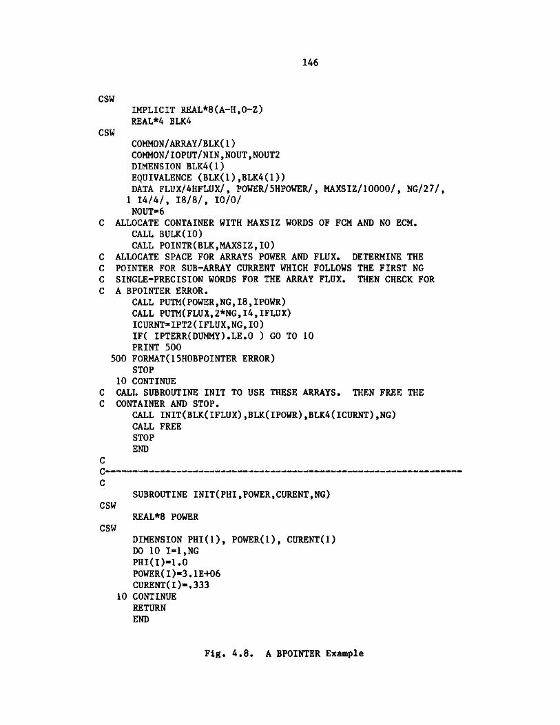
146
CSWIMPLICIT REAL*8(A-H,o-Z)REAL*4 BLK4
CSWCOMMON/ARRAY/BLK( 1)COMMON/IOPUT/NIN,NOUT,NOUT2DIMENSION BLK4(1)EQUIVALENCE (BLK(1),BLK4(1))DATA FLUX/4HFLUX/, POWER/5HPOWER/, MAXSIZ/10000/, NG/27/,1 14/4/, 18/8/, 10/0/NOUT=6
C ALLOCATE CONTAINER WITH MAXSIZ WORDS OF FCM AND NO ECM.CALL BULK(IO)CALL POINTR(BLK,MAXSIZ,IO)
C ALLOCATE SPACE FOR ARRAYS POWER AND FLUX. DETERMINE THEC POINTER FOR SUB-ARRAY CURRENT WHICH FOLLOWS THE FIRST NGC SINGLE-PRECISION WORDS FOR THE ARRAY FLUX. THEN CHECK FORC A BPOINTER ERROR.
CALL PUTM(POWER, NG, I8, IPOWR)CALL PUTM(FLUX,2*NG,I4,IFLUX)ICURNT=IPT2(IFLUX,NG,10)IF( IPTERR(DUMMY).LE.O ) GO TO 10PRINT 500
500 FORMAT(15HOBPOINTER ERROR)STOP
10 CONTINUEC CALL SUBROUTINE INIT TO USE THESE ARRAYS. THEN FREE THEC CONTAINER AND STOP.
CALL INIT(BLK(IFLUX),BLK(IPOWR),BLK4(ICURNT),NG)CALL FREESTOPEND
CC-----------------------------------------------------------------C
SUBROUTINE INIT(PHI,POWER,CURENT,NG)CSW
REAL*8 POWERCSW
DIMENSION PHI(1), POWER(1), CURENT(1)DO 10 I-1,NGPHI(I)-1.0POWER(I)-3.1E+06CURENT(I)-.333
10 CONTINUERETURNEND
Fig. 4.8. A BPOINTER Example

147
addressed in precisely the same manner as the first (FCM) container. The oneword assigned to the container by the applications program provides a refer-ence address. At execution time the function routines IGTLCM and IGTSCM areused to obtain the addresses of core which are available to the program forthe allocation of data arrays.
A few codes at the same time use BPOINTER and directly address ECM on two-level machines. In these programs the "LEVEL 2" BPOINTER reference commonblock must start at the first word of LCM. BPOINTER calculates address off-sets based on that assumption. DIF3D and most codes currently under develop-ment do not address ECM directly; they employ CRED and CRIT to transfer blocksof data between the two levels of memory.
Occasionally it is convenient to exercise the two-level implementation ona one-level machine. In such cases it is necessary to precede the BPOINTERinitialization call by the DOPC initialization call so that the user referenceaddress of the BPOINTER ECM container is initialized prior to the firstcall to CRED/CRIT (BPOINTER employs CRED/CRIT in its two-level implementation).A discussion of IGTLCM/IGTSCM and the associated assembler routines thatallocate these blocks of memory follows.
4.3.5.2 IGTLCM/IGTSCM/IGTXCM
Function IGTLCM and its associated entry points IGTSCM and IGTXCM managethe allocation of the ECM, FCM and XCM containers, respectively. The FCMcontainer always resides in fast memory (e.g. the FCM storage pool). TheECM container and the auxiliary ECM container named XCM both reside in thesame storage pool. On single-level machines they reside in the FCM storagepool along with the FCM container; on two-level machines like the CDC 7600they reside in LCM. If the CILV language flag is activated in a CDC 7600implementation then the ECM and XCM containers will be allocated in the FCMstorage pool along with the FCM container.
IGTLCM, IGTSCM and IGTXCM route all memory allocation requests throughfunction subroutine JGT which calls the appropriate assembler, Fortran orsystem routines. The calling sequence for IGTLCM is:
LOCECM = IGTLCM( NWORDS )
This call returns the (REAL*4) word address of the requested block of NWORDSwhich constitutes the ECM container. A similar call to IGTSCM or IGTXCMallocates the appropriate container. The function value of -1 is returned ifthe container allocation fails. Subroutine FRELCM with associated entrypoints FRESCM and FREXCM release the corresponding containers. The example inFigure 4.9 illustrates the use of the IGTLCM package. The function LOCFWDprovides the (REAL*4) word address of the reference variable used to addressthe container.
4.3.5.3 IBM Allocation
The assembler routine MYLCM with entry point MYSCM, FREELC and FREESC(called by JGT or FRELCM) uses the standard IBM macro instructions GETMAIN andFREEMAIN to allocate and free consecutive words of core which are availableto the program. The designations subpool 1 and 2 are assigned to the ECM and

148
COMMON /REFFCM/ BLK(1)CC ALLOCATE FCM CONTAINERC
LOCFCM = IGTSCM( NWORDS )IF ( LOCFCM .EQ. -1 ) GO TO 10
CC DETERMINE WORD OFFSET OF CONTAINER FROM REFERENCE ARRAY BLK(1)C
LFCREF = LOCFCM - LOCFWD ( BLK(1) )CC INITIALIZE CONTAINERC
DO 1 I=1,NWRDSBLK(LFCREF+I)=O.0
1 CONTINUE
CC FREE CONTAINERC
CALL FRESCM
CC ERROR EXITC
10 CONTINUE
Fig. 4.9. IGTSCM/FRESCM/LOCFWD Example

149
FCM containers, respectively. Since allocations are performed in units of256 (REAL*8) words, it is most efficient to request blocks of memory in suchmultiples.
Figure 4.10 shows a schematic diagram of a program and SCM container.
4.3.5.4 CDC Allocation
The COMPASS assembler routine JGTSCM with entry point JGTLCM (calledby JGT) uses the standard CDC macro instruction MEMORY to determine and tochange the job's SCM and LCM field lengths.
The FCM container is placed at the end of the user's SCM field length,as shown in Figure 4.10. The ECM container is placed at the end of the user'sLCM field. The last word of each container is four words short of the user'sSCM or LCM field length; this is done to avoid I/O problems in systems thatattempt to read ahead. The XCM container is allocated to provide space forindices to the random access records of the DOPC files on the CDC 7600 imple-mentation, only. The implementation uses mass storage routines (READMS,WRITES, OPENMS and CLOSMS) in the CDC library.
BPOINTER releases containers when they are no longer needed and returnsfield lengths to their original values.
4.3.5.5 CRAY Allocation (CTSS)
Two subroutines (LASTMEM and MEMORY) from the CRAY Time Sharing System(CTSS) Fortran Library at Los Alamos National Laboratory are called by JGT todetermine and change a job's field length, respectively. JGT establishes theuser program length (i.e. the high limit of user code, JCHLM) by an initialcall to LASTMEM. Each time a new container is requested JGT allocates spacein one of two ways:
1. If another container has been previously allocated, and there isenough free space between it and the program, the new container isestablished in the free space. The field length is not changed.
2. If adequate free space is not available MEMORY is called to increasethe field length, and the new container is placed such that theaddress of its last word is the new value of JCHLM.
Figure 4.11 shows a schematic diagram of fast core of a CRAY machine containinga program and two containers.
JGT reduces the field length by an appropriate amount only when the
container ending at address JCHLM is released.
4.3.5.6 CRAY Allocation (COS)
Dynamic memory allocation on machines using the standard CRAY OperatingSystem (COS) is implemented in a manner that is functionally equivalent to theCTSS implementation. CTSS subroutines MEMORY (2 arguments) and LASTMEM aresimulated on COS installations by the Fortran subroutine MEMGET and its entrypoint LASTMEM, respectively. A blank COMMON array of length 1 must belocated as follows in order for it to provide a reference point (JCHLM) forthe dynamic memory allocation:

150
load Im o d u l e I p r o g r a m I
I /ARRAY/BLK(1) I
p more I
| program I
subpool I1 I
subpool2
ECMcontainer
FCMcontainer
(a) on IBM machines
start of FCMfield length
i program I
S moreI program I
I free space I
I FCMI container I
I end of FCMfield length
(b) on CDC 7600 machines
Fig. 4.10. Fast-Core Allocation on IBM and CDC 7600 Machines
i
i

151
start of FCMfield length
program {
/ARRAY/BLK(1) I
moreI program
I FCM II container I
I ECM II container I
JCHLM ----- --- -- --
I -system tables II and buffers I
Fig. 4.11. Fast-Core Allocation on a CRAY Machine
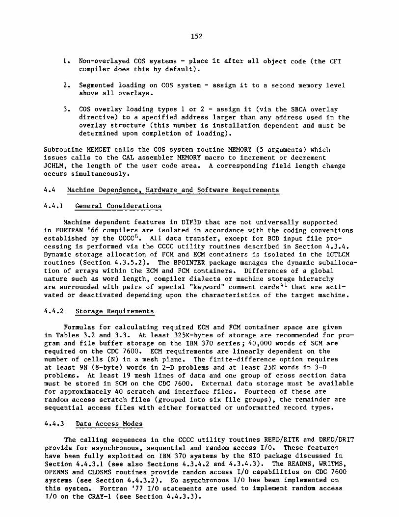
152
1. Non-overlayed COS systems - place it after all object code (the CFTcompiler does this by default).
2. Segmented loading on COS system - assign it to a second memory levelabove all overlays.
3. COS overlay loading types 1 or 2 - assign it (via the SBCA overlaydirective) to a specified address larger than any address used in theoverlay structure (this number is installation dependent and must bedetermined upon completion of loading).
Subroutine MEMGET calls the COS system routine MEMORY (5 arguments) whichissues calls to the CAL assembler MEMORY macro to increment or decrementJCHLM, the length of the user code area. A corresponding field length changeoccurs simultaneously.
4.4 Machine Dependence, Hardware and Software Requirements
4.4.1 General Considerations
Machine dependent features in DIF3D that are not universally supportedin FORTRAN '66 compilers are isolated in accordance with the coding conventionsestablished by the CCCC6. All data transfer, except for BCD input file pro-cessing is performed via the CCCC utility routines described in Section 4.3.4.Dynamic storage allocation of FCM and ECM containers is isolated in the IGTLCMroutines (Section 4.3.5.2). The BPOINTER package manages the dynamic suballoca-tion of arrays within the ECM and FCM containers. Differences of a globalnature such as word length, compiler dialects or machine storage hierarchyare surrounded with pairs of special "keyword" comment cards4 1 that are acti-vated or deactivated depending upon the characteristics of the target machine.
4.4.2 Storage Requirements
Formulas for calculating required ECM and FCM container space are givenin Tables 3.2 and 3.3. At least 325K-bytes of storage are recommended for pro-gram and file buffer storage on the IBM 370 series; 40,000 words of SCM arerequired on the CDC 7600. ECM requirements are linearly dependent on thenumber of cells (N) in a mesh plane. The finite-difference option requiresat least 9N (8-byte) words in 2-D problems and at least 25N words in 3-Dproblems. At least 19 mesh lines of data and one group of cross section datamust be stored in SCM on the CDC 7600. External data storage must be availablefor approximately 40 scratch and interface files. Fourteen of these arerandom access scratch files (grouped into six file groups), the remainder aresequential access files with either formatted or unformatted record types.
4.4.3 Data Access Modes
The calling sequences in the CCCC utility routines REED/RITE and DRED/DRITprovide for asynchronous, sequential and random access I/O. These featureshave been fully exploited on IBM 370 systems by the SIO package discussed inSection 4.4.3.1 (see also Sections 4.3.4.2 and 4.3.4.3). The READMS, WRITMS,OPENMS and CLOSMS routines provide random access I/O capabilities on CDC 7600systems (see Section 4.4.3.2). No asynchronous I/O has been implemented onthis system. Fortran '77 I/O statements are used to implement random access
I/O on the CRAY-1 (see Section 4.4.3.3).

153
4.4.3.1 SIO, a random access, asynchronous I/O package for IBM systems
In order to make efficient use of large computers such as the IBM System370 Model 195 or 3033 at Argonne National Laboratory, a program must attemptto optimize both its central processor and peripheral processor operations.Most large scientific programs are written in Fortran, a high level languagewhich provides little flexibility in specifying efficient I/O methods.Several Fortran codes have, however, been designed which would profit bythe availability of a program package with the following characteristics:
1. permits asynchronous operation;
2. performs random access operations efficiently;
3. handles large records efficiently;
4. performs I/O operations without the need for buffers.
The SIO program package was written to provide a Fortran-callable accessmethod with these characteristics.
The two IBM-supplied Fortran I/O programs which come closest to satisfyingthese requirements are the Fortran IV (H Extended) asynchronous I/O and theFortran IV Direct Access I/O.
The Asynchronous I/O uses V-type records which include control informationin each record. Hence buffers are essential. However, with records longerthan two tracks on standard direct access devices, the buffers become essen-tially useless in increasing I/O efficiency, since almost the entire I/Ooperation must be completed before the user can access the data. Furthermore,these buffers consume large amounts of core, and additional central processoreffort is required to move the data between program locations and the buffer.In addition to buffering the data, the Asynchronous I/O operations are sequen-tial and there are no efficient methods for accessing records in a randommanner.
Fortran Direct Access I/O does permit random access of the data file,but it is essentially limited to track-length records. This could be overcomethrough keeping track of the location of each record in an index table anddoing software spanning. Since Direct Access I/O uses V-type records, buf-fering is required. There is also a substantial overhead incurred in theinitial formatting of the direct access data set when the file is firstopened. Furthermore, asynchronous operation is impossible.
The first step toward attaining a capability with the attributes notedabove was to study the IBM I/O routines accessible through standard systemMacro calls. Of these, the Basic Sequential Access Method (BSAM) was chosenbecause it could be used to randomly access records through the Point Macro;it supported U-format records which contain no control information withinthem; and it features chained scheduling which allows several tracks to beaccessed without relinquishing the input/output channel and so decreasingI/O time. As with the Direct Access method, it was necessary to use an indextable which contains the relative location of each record and its length. Acopy of this table resides in core and also occupies the first track of the

154
data set. The problem of formatting the data set was overcome by alwaysappending a new record to the end of the data set regardless of which logicalrecord it might be. When records are updated, they are written over theold record if possible, or else appended to the end of the data set like anew record. Asynchronous operation is achieved through subtasking the actualcode to do the I/O.
The SIO program package consists of two central modules (SIO and SIOSUB)along with a few auxiliary routines used for edit and error processing(SIOTRC,SIoERR,SIOWU6). In addition the capability may be invoked usingthe standard I/O routines REED/RITE which branch to the SIO access methodfor datasets defined with the job control record format U, i.e. RECFM=U. Thetwo main modules consist of a subroutine (SIO) which is included in the mainprogram (task) through appropriate linkage editor control statements and aself-contained load module (SIOSUB) which operates as a subtask after beingATTACHed by the subroutine SIO. There are two assembly parameters in themodules SIO and SIOSUB which are of interest to the user. They are NBLKSand MAXFILES. NBLKS sets the length of the index table discussed above(called the File Control Block or FCB) and determines the maximum number ofrecords which may be placed in the file. For NBLKS=1, 431 entries are allowed;for NBLKS=2, 943 entries are allowed; for NBLKS=3, 1455 entries are allowed;for NBLKS=4, 1967 entries are allowed, but this option is available only ifthe SIO files are on direct access devices with a track length greater thaneight kilbyotes. The parameter MAXFILES specifies the maximum number offiles which may be open at a single time. The two parameters are routinelyset at NBLKS=2 and MAXFILES=50. The variables must be identically definedboth in the main task (SIO) and the subtask (SIOSUB) and files created with aspecific value of NBLKS may not be accessed by versions of SIO with a differentvalue of NBLKS.
4.4.3.2 Implementation Considerations on the CDC 7600
Random access I/O on the CDC 7600 is implemented using the routinesOPENMS, CLOSMS, READMS and WRITMS found in the Fortran utility library.Auxiliary storage equal in length to the number of records in the file must besupplied during the OPENMS call for each file. An auxiliary ECM containernamed XCM is allocated directly from DOPC by calling entry point IGTXCM in theIGTLCM dynamic storage allocation subroutine package. Consequently, DOPCand DRED/DRIT depend only on IGTXCM for dynamic storage allocation.
The subscript index limitation of 131071 words imposed on CDC 7600LCM arrays is effectively raised to 393213 by employing two routines DRED1and DRED2 each of which addresses a successively higher block of 131070 wordsof ECM. The circumvention is accomplished by passing the initial address ofthe next adjacent block of 131070 words of ECM to the appropriate routine,DRED1 or DRED2.
4.4.4 Vectorization on the CRAY-1
Although DIF3D was not designed for a pipelined computer such as theCRAY-1, an advanced computer performance evaluation project42 at Argonne ledto the implementation of a vectorized variant of the SLOR algorithm applicableto nonperiodic, orthogonal geometry models. The regular mesh structure andthe fact that at least 75% of the DIF3D scalar execution time is spent in a

155
small kernel of subroutines that perform the SLOR algorithm provided ampleopportunity for vectorizing (with vector lengths J/2) the dominant computationsin DIF3D without changing the DIF3D data structure.
The vector pipeline of the CRAY-1 is exploited by simultaneously solvingthe tridiagonal matrix equations generated for the (J+1)/2 odd lines on a meshplane, and then simultaneously solving the corresponding tridiagonal matrixequations generated for the J/2 even lines on a plane. This odd/even (red/black)SLOR algorithm4 3 ,44 was implemented within the existing DIF3D data structureby modifying subroutine OSWEEP and by increasing one auxiliary mesh line array(SOLN) to the size of a mesh plane array. The CRAY-1 version of OSWEEP callsRBOSRC and RBOSOR, the vectorized counterparts of the ROWSRC and SORINVsubroutines, twice for each mesh plane k before processing plane k + 1; thefirst pass processes the odd numbered lines on plane k and the second passprocesses the even numbered lines.
A comparison of the relative megaflop rates (millions of floating pointoperations per second) achieved by the scalar (conventionally ordered) and the
vector (odd/even ordered) algorithms, when applied to the two-dimensional IAEAbenchmark problem with a (170 x 170) rectangular mesh, is tabulated in Table 4.5.
The results4 5 in Table 4.5 should be viewed in light of three considera-tions. First, one expects a factor of 2.3 increase in megaflop rates on theCRAY-1 due to machine clock cycle differences (12.5 nanosecs on the CRAY-1 vs.28.5 nanosecs on the IBM 370/195). Second, the ROWSRC subroutine in theso-called scalar algorithm will vectorize on the CRAY-1. Third, the megafloprate of the current, vectorized algorithm is dependent on the problem in tworespects. The vector length depends on the number of lines (J) on a plane;the vector stride (the number of memory words between successive vectorelements) of length 21 will cause memory bank conflicts whenever
Table 4.5. Execution Rates for the 2D IAEA Benchmarka
Method/Machine Cray-1 IBM 370/195
Vector Fortran 4.4 0.83(RBOSRC, RBOSOR)
Scalar Fortran 1.6 -(ROWSRC, SORINV)
Scalar Fortran withAssembler SORINV 2.7 1
aRates are expressed in units of 3.9 megaflops. The
2 group model is defined with a 1 cm (170 x 170) mesh.
the line length I is a multiple of 8 on the typical 16 memory bank machine.Work in progress towards implementation of a vector length of J*K/2 shouldyield favorable performance increases for a wider class of problems withoutsignificantly altering the DIF3D data structure.
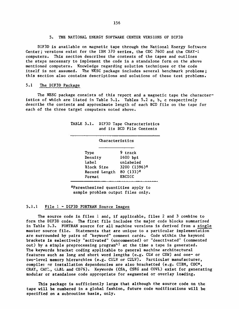
156
5. THE NATIONAL ENERGY SOFTWARE CENTER VERSIONS OF DIF3D
DIF3D is available on magnetic tape through the National Energy SoftwareCenter; versions exist for the IBM 370 series, the CDC 7600 and the CRAY-1computers. This section describes the contents of the tapes and outlinesthe steps necessary to implement the code in a standalone form on the abovementioned computers. Knowledge regarding solution techniques or the codeitself is not assumed. The NESC package includes several benchmark problems;this section also contains descriptions and solutions of these test problems.
5.1 The DIF3D Package
The NESC package consists of this report and a magnetic tape the character-istics of which are listed in Table 5.1. Tables 5.2 a, b, c respectivelydescribe the contents and approximate length of each BCD file on the tape foreach of the three target computers noted above.
TABLE 5.1. DIF3D Tape Characteristics
and its BCD File Contents
Characteristics
Type 9 trackDensity 1600 bpiLabel unlabeledBlock Size 3200 (1596)aRecord Length 80 (133)aFormat EBCDIC
aParenthesized quantities apply to
sample problem output files only.
5.1.1 File 1 - DIF3D FORTRAN Source Images
The source code in files 1 and, if applicable, files 2 and 3 combine toform the DIF3D code. The first file includes the major code blocks summarizedin Table 5.3. FORTRAN source for all machine versions is derived from a singlemaster source file. Statements that are unique to a particular implementationare surrounded by pairs of "keyword" comment cards. Code within the keywordbrackets is selectively "activated" (uncommented) or "deactivated" (commentedout) by a simple preprocessing program4 1 at the time a tape is generated.The keywords bracket coding applicable to general machine architecturalfeatures such as long and short word lengths (e.g. CLW or CSW) and one- ortwo-level memory hierarchies (e.g. C1LV or C2LV). Particular manufacturer,compiler r installation dependencies are also bracketted (e.g. CIBM, CDC*,CRAY, CAIL, CLBL and CD76). Keywords (CSA, CSEG and COVL) exist for generatingmodular or standalone code appropriate for segmented or overlay loading.
This package is sufficiently large that although the source code on thetape will be numbered in a global fashion, future code modifications will bespecified on a subroutine basis, only.

157
TABLE 5.2a. Contents of NESC Export Tape for IBM 370 Systems
File Estimated NumberNumber Contents of Card Images
1 DIF3D FORTRAN Source Code 791962 Machine Dependent Source Code 14983 SIOSUB Subtask (IBM) Assembler 12284 Loader Directives 1945 ARCSPO21 JCL Procedure 2826 Sample Problem Input (Cases 1, 2, 3 and 4) 2267 Sample Problem Input (Cases 5 and 6) 1618 Sample Problem Output (Cases 1, 2, 3 and 4) 39369 Sample Problem Output (Cases 5 and 6) 2392
10 CCCC and Code Dependent File Descriptions 5431
TABLE 5.2b. Contents of NESC Export Tape for CDC 7600 Systems
File Estimated NumberNumber Contents of Card Images
1 DIF3D FORTRAN Source Code 791962 Loader Directives 1213 Sample Problem Input (Cases 1, 2, 3 and 4) 2264 Sample Problem Input (Cases 5 and 6) 1615 Sample Problem Output (Cases 1, 2, 3 and 4) 39366 Sample Problem Output (Cases 5 and 6) 23927 CCCC and Code Dependent File Descriptions 5431
TABLE 5.2c. Contents of NESC Export Tape for CRAY-1 Systems
File Estimated NumberNumber Contents of Card Images
DIF3D FORTRAN Source Code 79196
2 Machine Dependent Source Code (optional) 1773 Loader Directives 1214 Sample Problem Input (Cases 1, 2, 3 and 4) 2265 Sample Problem Input (Cases 5 and 6) 1616 Sample Problem Output (Cases 1, 2, 3 and 4) 39367 Sample Problem Output (Cases 5 and 6) 23928 CCCC and Code Dependent File Descriptions 5431

158
TABLE 5.3. DIF3D Code Blocks
Principal Approximate NumberCode Blocks of Card-Images
D3DRIV (+ utilities) 9537SCAN 306STUFF 730GNIP4C 23043HMG4C 4745MODCXS 938BCDINP 1176S4C10A 2625DIF3D 36056UDOIT1,2,3,4 40
5.1.2 Machine Dependent Source Code
Most compilers (except for the FTN compilers on the CDC 7600) do notpermit the intermixing of FORTRAN and assembler source code. File 2, there-fore, segregates assembler code from the FORTRAN coding on File 1 for compu-ters other than the CDC 7600. Some of the assembler code located on File 2is provided solely for the purpose of optimizing CPU performance, and isoptional in this respect.
On the tape destined for IBM installations, file 2 contains IBM assemblercode for dynamic storage allocation and for asynchronous, random access I/Oprocessing. File 3 on this tape contains the IBM assembler source code forthe SIOSUB subtask which is required for the DIF3D random access I/O implemen-tation on IBM 370 systems. See the explanation in Section 5.4.3.
On the tape destined for the CDC 7600, assembler subroutines for dynamicstorage allocation, for transfers between ECM and SCM and for optimizingSORINV (the subroutine which performs the back substitution and overrelaxationtasks in the SLOR solution of the tridiagonal matrix equations) are appropri-
ately located with their FORTRAN counterparts and associated routines on file 1.
File 2 on the CRAY-1 tape contains an assembler coded optimized versionof the (non-vectorizable) SORINV routine mentioned in the previous paragraph.Subroutines RBOSOR and RBOSRC for the vectorizable (odd/even ordering) SLORalgorithm are present on file 1 (see Section 4.4.4).
5.1.3 Loader Instructions
Instructions for creating the DIF3D overlay or segment structure areincluded for the convenience of the user. Linkage editor instructionsare provided on the NESC tape for IBM 370 systems (see also Appendix E).Instructions for the SEGLINK segmented loader at Lawrence Berkeley Laboratoryare included on the CDC 7600 tape (see also Appendix F.1). Type 01 overlaydirectives are included with the CRAY-1 tape (see also Appendix F.2). Asnoted in Section 5.1.1 all tapes have overlay calls and directives presentin the FORTRAN source; these are appropriately activated (uncommented) on theCDC 7600 and CRAY-1 tapes (see Section 5.2.1).

159
5.1.4 Sample Problem Input and Output
Six problem cases are supplied; four of these cases arise from two- andthree-dimensional models of the well-known SNR Benchmark Problem46,47in four energy groups. Solutions for both the finite-difference triangulargeometry option and the nodal hexagonal geometry options are generated forthese two models. Two- and three-dimensional models of the well-known IAEAbenchmark problem48 with two energy groups provide the remaining two test
problems. Finite-difference solutions of these orthogonal geometry (XY andXYZ) problems are generated. Section 5.3 describes the benchmark problems.
Each sample problem was run on the IBM 370 system at Argonne and thecorresponding output, including carriage control symbols, is provided on theNESC tape. The output files will consequently have a record length of 133characters.
5.1.5 ARCSPO21, An Instream JCL Procedure for IBM 370 Systems
ARCSPO21, the instream JCL procedure appropriate for running the NESCversion of DIF3D on IBM systems is provided for the convenience of the user.It is listed in Appendix A and a discussion of its parameters appears inSection 3.12.3.
5.1.6 CCCC and Code-Dependent Interface File Descriptions
The file descriptions for the various interface files used in DIF3D areprovided on the tape to allow the user to inexpensively generate additionalcopies. These descriptions also appear in the Appendices B, ' -nd D of thisreport.
5.2 Implementation of the NESC DIF3D as a Stand-Alone Program
5.2.1 Code Structure and Loading Instructions
Table 5.3 lists the major code blocks within the DIF3D code system;functional descriptions of these code blocks appear in Section 4.1. A minimaloverlay structure, other than no overlays at all, uses these major codeblocks as primary overlays and D3DRIV as the root overlay. A detailed overlaystructure is given for the major code blocks GNIP4C, HMG4C and DIF3D inFigures 4.2, 4.3 and 4.4, respectively. On systems restricted to three overlaylevels, a root segment with primary and secondary overlays only (e.g. CDC 7600overlay loader or the type 01 overlay directives on the CRAY-1), subroutineDIF3D is assigned to the root segment as a logical extension of the mainriverr D3DRIV. This puts the major overlays of the neutronics solution at thesame (primary overlay) level as the remaining code blocks GNIP4C, HMG4C, etc.
Source code for the major code blocks is on File 1 of the NESC tape;code generated from assembling the mar'Kne-dependent source (if present) onFile 2 should be included at load time with the root segment. Loading instruc-tions for the target computers are included in the appropriate files noted inTables 5.2 a, b, c. Also present within the source code are appropriatelyinactivated (e.g. commented) or activated (uncommented) overlay directives forthe CDC 7600 and CRAY-1 computers. Appendices E, F.1 and F.2 display the jobcontrol language and the loader directives required to create the DIF3D loadmodules for each computer.

160
SIOSUB, a separate subtask module (file 3), is required to implementthe random access I/O capability used by DIF3D on IBM systems. The nextsection describes its relation to the SIO access method and its placement inthe STEPLIB data set prior to execution.
5.2.2 SIO
The SIO access method provides a random access, asynchronous I/O capabilityon IBM operating systems. Within DIF3D the SIO routines are invoked directlyfrom the CCCC generalized I/O subroutines REED and RITE. The source codefor SIO is included as part of the DIF3D standalone code and requires specialcare with regard to its implementation. In particular, SIO is made up of anassembler language module, SIOSUB, and three assembler subroutines, SIO, RECFMand SIOTRC. The latter routines are assembled and included within the rootsegment of the DIF3D load module in a manner completely analagous to Fortranroutines such as REED and RITE. The subroutine RECFM is called by REED/RITEto interrogate the DCB of a dataset to determine whether it has been desig-nated with an undefined record format, i.e. RECFM=U. If so, it is consideredan SIO dataset and the subroutine SIO is called to perform the I/O ratherthan the Fortran system routine IBCOM#. The subroutine SIO sets up argumentlists and then passes control to the load module SIOSUB to perform the actualI/O operations. Thus, in addition to the DIF3D load module, a second loadmodule, SIOSUB, must be available to the system at the time of execution ofDIF3D, i.e. SIOSUB must be a member of a partitioned data set referenced inthe STEPLIB data definition JCL of the job step. To create the load moduleSIOSUB, it is necessary to assemble the source code and link edit the resultingobject code using standard procedures. It is however essential that the loadmodule SIOSUB be assigned the "Re-enterable" attribute by the linkage editor.This may be done by assigning the parameter RENT in the PARM field of thelinkage editor execution step as follows:
//LKED EXEC PGM=IEWL,PARM='RENT,...'
5.2.3 File Number Assignments
All sequential binary files (input and output interface files and scratchfiles) used in the DIF3D code system are handled through the CCCC standardsubroutines SEEK, REED and RITE. The assignment of file numbers to filenames and the initialization of the SEEK tables is done from the DIF3D driverD3DRIV (also known as MAIN on IBM systems). Subroutine SEEK is also used toobtain reference numbers for sequential BCD interface files; the subroutineSEKPHL is then used to obtain corresponding logical unit numbers for subsequentuse with FORTRAN READ and WRITE statements. SEKPHL is also called to rewind(close) all BCD data sets. Section 4.3.4 describes these functions.
Fourteen random access scratch files are exclusively referenced by the
CCCC standard subroutines DOPC, DRED and DRIT;.only the DIF3D neutronicssolution code block references these files. File names RNDM01-RNDM14 correspondto DOPC reference numbers 1-14, respectively. The Argonne implementation ofthe DOPC, DRED and DRIT package uses subroutine SEEK to assign logical unitreference numbers to the 14 DOPC reference numbers. Except for notedexceptions, all DOPC calls are issued from subroutines SSDISK or NHDISK in theDIF3D initialization segment SSINIT. The exceptions are the DOPC initializationand termination calls in subroutine DIF3D, the driver for the DIF3D neutronics

161
module proper, and a DOPC call required in subroutine XSREV, the adjoint crosssection reversal subroutine. In the latter case, DOPC file group 6 is deletedand redefined with a potentially different record size in its lone member file.
Table 5.4 lists all of the files used by the code blocks in the NESCversion of DIF3D and classifies them into one of five different categoriesthat have already been defined in Section 4.2 for the Argonne productionversion of DIF3D. As shown in the table, printer output is written to file 6and optionally to file 10. BCD input data is read from file 5; BCD or binaryinterface files which exist at the start of a job will be read from theirrespective files. The DOPC data sets in Table 5.4 have previously been definedin Table 4.3.
TABLE 5.4. Data Set Classification for the NESC DIF3D
FileReference File File FileNumber Name Typea Description
5 BCD input data for SCAN module6 BCD output data all modules9 BCD input data spool from SCAN
10 BCD auxiliary output all modules11 A.DIF3D BCD DIF3D control12 A.NIP3 BCD GNIP4C control13 A.HMG4C BCD HMG4C control15 A.ISO BCD BCD ISOTXS18 DIF3D CDB DIF3D control19 COMPXS CDB macroscopic cross sections20 LABELS CDB labels, half-heights22 D3EDIT CDB tabular edits spool23 NHFLUX CDB nodal restart (real)24 NAFLUX CDB nodal restart (adjoint)25 PKEDIT CDB peak power/flux interface26 GEODST CCCC geometry description27 ISOTXS CCCC microscopic cross sections28 NDXSRF CCCC nuclide/zone reference29 ZNATDN CCCC zone nuclide atom densities30 RTFLUX CCCC real flux31 ATFLUX CCCC adjoint flux32 FIXSRC CCCC fixed source33 RZFLUX CCCC zone flux averages34 PWDINT CCCC power density39 SEARCH CCCC SRCH4C control
41-56b RNDMnn DOPC random access scratch files66-71 SCRO01-6 SCR scratch files76-78 UDOIT CDB UDOIT versions 1-3
80 AUDOIT BCD UDOIT module input
aSee Section 4.2. CDB denotes a code-dependent binary file.
bTable 4.3 describes the 14 DOPC files. Reference numbers 44 and 50are undefined.

162
File assignments may be easily reassigned by changing source code inD3DRIV; no other routines need be modified. All files are written sequen-tially (one minor exception is noted in Section 4.4.3; it applies to adjointcalculations with upscatter). If necessary, all files may be read sequentially.Greater efficiency is achieved when random access I/O methods are employed.Reading the flux file in the inscatter source calculation and the flux andfinite-difference coefficient files during the concurrent inner iteration strategyare the principal I/O operations affected by this access method.
5.2.4 Running the NESC version of DIF3D
DIF3D is designed to run in environments in which codes that follow theCCCC standards may have never before been implemented. If desired, all inputdata may be entered in BCD form. BCD input processors within the DIF3D codesystem will subsequently convert this data to the necessary CCCC and code-dependent binary interface files. Existing BCD or binary interface fileswill also be accepted by DIF3D. Table 4.2 summarizes the input and outputinterface files for each code block within the DIF3D code system. Thecontents and formats of the BCD and binary interface files are given in theinterface file descriptions in Appendices B-D. The sample problem input dataon the NESC tape is entirely in BCD format.
The BCD data format principally consists of sets of card images havinga two-digit card type identifier in columns 1 and 2. Frequently, severalcards of the same type are required; the ordering of cards within a given typeis usually fixed. Data associated with a particular file is preceded by thecard image DATASET=filename and terminated by another DATASET=filename cardfor the next file, by a BLOCK=STPO21 card or by an end-of-file indicator.Alternative keywords to DATASET (e.g. UNFORM, NOSORT and MODIFY) are describedin Section 3.2; these provide free field input, special dataset treatment(e.g. A.ISO), and permit modification of specified card types (replacement ordeletion), respectively. Preceding a collection of DATASETs must be a BLOCK=STPO21 card image. Each such BLOCK invokes another execution of DIF3D. OldDATASETS (files) which already exist at the start of a job are specified inthe BLOCK=OLD block. The list of old DATASETs consists of card images of theform DATASET=filename.
Most systems require users to specify memory size and CPU time estimatesin a JOB control statement (see JOB Control examples in Section 3.12, Figs.3.5, 3.8 and 3.9). DIF3D jobs require a fixed amount of storage to containthe longest program overlay and I/O buffers, and a problem-dependent minimumamount of computer memory for the FCM and ECM data storage containers (seeSection 3.9). The FCM and ECM container sizes specified in the sample probleminput are appropriate for the CDC 7600, but they may also be used (lessefficiently) on the other target computers. The length of the longestoverlay is installation dependent and can be obtained by examining the outputfrom a successful loader job. The amount of space required for I/O buffersis also installation and implementation dependent; at a given moment the
maximum number of files that are opened is problem dependent, but should notexceed 14 (the number of DOPC files). This number does not include the threeBCD input and output file unit numbers 5, 6 and 10. A practical estimate maybe closer to 6 or 7 simultaneously open files.

163
For IBM and CRAY-1 systems region sizes specified on the JOB card providean upper bound on the allowable memory to be used for both program instructions
and dynamically allocated storage containers. On the CDC 7600, the FCM andECM field length requests should only include space required for the longest
overlay; additional space will be dynamically allocated via calls to IGTLCM orIGTSCM from the BPOINTER package. The sample problem discussions which followinclude container size and CPU time estimates for each problem.
5.3 Sample Problems
Six problem cases are derived from two benchmark source situations.Summarized in Table 5.5 are estimates of typical FCM and ECM container sizes
that are appropriate for running the sample problems on the designated
computers. For implementations on the IBM 3033 or CRAY-1 computers these
estimates may optionally replace the container sizes (on the A.DIF3D type 02
card) supplied with the sample problems on the NESC tape. As noted above thesupplied sizes are appropriate for the CDC 7600. The relatively large
container sizes suggested for the CRAY-1 (operating under the CRAY TimeSharing System at Los Alamos National Laboratory) reduce expensive I/O costs
in favor of less expensive memory residence charges. Because sample problems
1-4 are combined in a single job (as are sample problems 5-6), JOB regionsize or field length calculations are governed by the largest container sizes
in each problem set (i.e. problems 4 or 6).
5.3.1 The SNR Benchmark Problem
The SNR benchmark problem46,47 is a 4-group model of a 300 MWe
homogeneous-core LMFBR originally specified in both Cartesian and triangulargeometry. The modified problem 547 solved here is obtained by altering
the outer boundary of the triangular-geometry model (while preserving thevolume of the core) to allow imposition of boundary conditions along surfaces
of hexagons. The model consists of a two-zone core surrounded by radial and
axial blankets without a reflector. The height of the active core is 95 cm,and each axial blanket is 40 cm thick. A total of 11 rings of hexagons(including the central hexagon) are included in the model, with a lattice
pitch of 11.2003 cii. Jin=0 boundary conditions are imposed on the outersurfaces of the blankets. The full-core model includes a total of 18 controlrods, with 6 of these rods parked at the core-upper axial blanket interface,and the remaining 12 inserted to the core midplane. As in Ref. 5, all calcu-lations are performed using sixth-core symmetry.
5.3.1.1 The Two-Dimensional Model
Figure 5.1 displays the BCD input data contained on the NESC tape for
the two-dimensional SNR benchmark problem. Two cases corresponding to thefinite-difference and the nodal solution options are specified. Data following
the second BLOCK=STPO21 in Fig. 5.1 invokes the nodal solution option. TheREMOVE=filename cards located after the second BLOCK=STPO21 card turn off the
existence sentinels for the corresponding file names in the SEEK table beforeprocessing begins for the second case. Selected printed and plotted outputfrom these two cases is displayed in Appendices G.1 and G.2. Included are
a geometry map, a mesh cell to region map, macroscopic cross section editsand tabulations of region and area integrals for power density, total flux
and neutron balances.

164
TABLE 5.5. Resource Estimates for Sample Problems 1-6
Problem and Container Size CPU TimeComputer FCM ECM (Seconds)b
Sample 1 - 2D SNRFinite Difference Option
IBM 3033 450 4300 2.8CDC 7600 3600 6000 1.7CRAY-1 550 11250 1.9
Sample 2 - 2D SNRNodal OptionIBM 3033 550 5700 1.8CDC 7600 4000 5700 1.0CRAY-1 600 6100 1.6
Sample 3 - 3D SNRNodal OptionIBM 3033 600 27000 21CDC 7600 20000 27000 11CRAY-1 650 61000 11
Sample 4 - 3D SNRFinite Difference OptionIBM 3033 550 15300 147CDC 7600 12000 164000 81CRAY-1 650 450000 42
Sample 5 - 2D IAEA ProblemFinite Difference OptionIBM 3033 800 62000 60CDC 7600 20000 102000 25CRAY-1 8040 102000 11
Sample 6 - 3D IAEA ProblemFinite Difference OptionIBM 3033 400 94000 74CDC 7600 8000 166000 36CRAY-1 800 166000 19
aUnits are decimal number of longwords (REAL*8 words on IBMsystems). JOB region size calculations are given by:
IBM 3033: REGION = 325K + (FCM + ECM)/(128 words/K byte)CDC 7600: SCM = 100,0008 + FCM (octal words)
LCM = SCM + ECM + buffers (octal words)CRAY-1 : REGION = 200000 + FCM + ECM (decimal words)
(unoverlayed)
bCPU times on the IBM 370/195 are approximately 30 to 50% lessthan on IBM 3033.

//SNR2D3D JOB REGION-1700K,TIME-8,CLASS-X//*MAIN LINES-25,ORG-PRO// EXEC ARCSPO21//SYSIN DD *BLOCK-STPO21UNFORM-A.DIF3D01 **** SAMPLE PROBLEM 1 **** 2D SNR BENCHMARK - RODS IN - FD0602 1600 850003 00045005004 1 0 0 11 111 10 100 1 0 005 1.0E-10 1.0E-10 1.0E-1006 1.0 0.001 0.04 0.5UNFORM-A.NIP301 **** SAMPLE PROBLEM 1 **** 2D SNR BENCHMARK - RODS IN - FD0602 0 1 100000500 0 0 0 0 103 7004 740405 XU .5000 1 405 YU .5000 1 414 M1 I1 1.014 M2 12 1.014 M3 13 1.014 M4 14 1.014 MS 15 1.014 M6 16 1.015 M1 IC15 M2 OC15 M3 RB15 M5 CR
15 M6 CF29 11.2003 11 130 IC 130 IC 230 IC 330 IC 430 IC 530 IC 630 OC 6 130 OC 730 OC 830 RB 930 RB1030 RB 8 130 OC 9 4 530 OC 9 45 4630 RB 11 5 630 RB 11 56 5730 CR 7 330 CR 7 3530 CF 4 1NOSORT-A.ISOOV IOTXS HH2 *GFK 3D BNCH * 11D 4 6 0 3 0 1 1 12D *NA COOLED FBR BENCHMARK FOUR GROUP CPOSS SECTIONS
* *I1 12 13 14 15 160.768 0.232 0.0 0.01.72336E+09 4.02463E+08 7.97003E+07 3.15946E+07 1.05 E+07 8.00 E+0510000. 1000. 0.0
0 3 6 9 12 154D I1 GFK 1100. 0.0 0.0 0.0 0.0 0.0
0 0 1 0 0 0 0 0 1 1 0 2001 1 2 3 4 1 1 1 1
5D .11587 - .21220 .46137 .34571 .11587.21220 .46137 .34571 .69059 E-031.830758E-03 .92948 E-02
.17305 E-01 .39123 E-02 .18286 E-02 .36334 E-02 .92415 E-02 3.0360662.912173 2.881874 2.8795117D 0.0 0.0 .023597 0.0 .16153 E-02.40791 E-05 0.0 .46838 E-02 .42309 E-07 .44493 E-074D 12 GFK 1100. 0.0 0.0 0.0 0.0 0.0
0 0 1 0 0 0 0 0 1 1 0 2001 1 2 3 4 1 1 1 1
SD .11588 .21213 .46770 .35349 .11588.21213 .46770 .35349 .66221 E-031.83956 E-03 1.00354E-02.20476 E-01 .48531 E-02 .26377 E-02 .51332 E-02 .13238 E-01 3.0790632.914926 2.884945 2.8825357D 0.0 0.0 .023262 0.0 .15718 E-02.46451 E-05 0.0 .43414 E-02 .40724 E-07 .49968 E-074D 13 GFK 1
100. 0.0 0.0 0.0 0.0 0.00 0 1 0 0 0 0 0 1 1 0 2001 1 2 3 4 1 1 1 1
5D .14584 .28443 .52703 .40732 .14584.28443 .52703 .40732 1.11527E-033.063463E-031.002116E-02
.129995E-01 .2'688 E-02 .44347 E-04 .12274 E-03 .34952 E-03 2.7964102.440977 2.423171 2.4229517D 0.0 0.0 .032071 0.0 .27776 E-02.38880 E-05 0.0 .58971 E-02 .90018 E-07 .45039 E-074D 14 GFK 1100. 0.0 0.0 0.0 0.0 0.0
0 0 1 0 0 0 0 0 1 1 0 2001 1 2 3 4 1 i 1 1
SD .12270 .23133 .46274 .33749 .12270.23133 .46274 .33749 8.2278 E-042.170873E-03 7.64083E-03.97185 E-02 .19453 E-02 .31065 E-04 .87566 E-04 .23769 E-03 2.7902642.441880 2.423086 2.4229887D 0.0 0.0 .026322 0.0 .22889 E-02.28907 E-05 0.0 .53536 E-02 .62133 E-07 .33248 E-074D 15 GFK 1100. 0.0 0.0 0.0 0.0 0.0
0 0 0 0 0 0 0 0 1 1 0 2001 1 2 3 4 1 1 1 1
5D .13317 .25355 .58044 .54168 .13317.25355 .58044 .54168 .186696E-02 .126433E-01 .634405E-01.168687D_0.0 0.0 .022946 0.0 .37687 E-02
* .10320 E-05 0.0 .86815 E-02 .70361 E-11 .10489 E-07
Fig. 5.1. Input Data for the Four SNR Benchmark Problem Models
N-
V7

4D 16 GFK 1100. 0.0 0.0
0 0 0 0 01 1 2 3 4
5D .072206 .11487 .32642.11487 .32642 .19272.78660 E-037D 0.0 0.0 .01294
.68780 E-06 0.0 .34533 E-(BLOCK-STPO21,3REMOVE-GEODSTREMOVE-COMPXSREMOVE-NDXSRFREMOVE-ZNATDNREMOVE-LABELSREMOVE-RTFLUXMODIFY-A.DIF3D01 **** SAMPLE PROBLEM 2 ****02 '00 550011 1 40.0 1 87.5 1 135.011 1 175.0UNFORM-A.NIP301 **** SAMPLE PROBLEM 2 ****
03 114BLOCK-STPO21,3REMOVE-GEODSTREMOVE-COMPXSREMOVE-NDXSRFREMOVE-ZNATDNREMOVE-LABELSREMOVE-RTFLUXREMOVE-NHFLUXREMOVE-DIF3DUNFORM-A.DIF3D01 **** SAMPLE PROBLEM 3 ****02 2000 60000 003 0 0 0 4500 3004 100001101010010005 1.0E-7 1.0E-5 1.0E-506 1.0 0.001 0.04 0.511 1 40.0 1 87.5 1 135.011 1 175.0UNFORM-A.NIP301 **** SAMPLE PROBLEM 3 ****02 0 1 8000 0 500 0 0 003 12404 7 4 0 4 4 405 XU .5000 1 405 YU .5000 1 405 ZL .5000 1 405 ZU .5000 1 409 Z 2 40.0 2 87.5 2 135.009 Z 2 175.014 M1 11 1.014 M2 12 1.014 M3 13 1.014 M4 14 1.0
0.0 0.0 0.00 0 0 1 1 0 2001 1 1 1
.19272 .072206.216305E-03 .16880 E-03 .11468 E-02
42 0.0 .12871 E-0202 .43633 E-11 .69903 E-08
2D SNR BENCHMARK - RODS IN - NODAL
2D SNR BENCHMARK - RODS IN - NODAL
3D SNR BENCHMARK - RODS IN - NODAL
3D SNR BENCHMARK - 8 PLANES - NODAL0 0
14 M5 15 1.014 M6 16 1.015 M1 IC15 M2 OC15 M3 RB15 M4 AB15 M5 CR15 M6 CF29 11.2003 11 130 AB 1 0 0 0.0 175.030 IC 1 0 0 40.0 135.030 AB 2 0 0 0.0 175.030 IC 2 0 0 40.0 135.030 AB 3 0 0 0.0 175.030 IC 3 0 0 40.0 135.030 AB 4 0 0 0.0 175.030 IC 4 0 0 40.0 135.030 AB 5 0 0 0.0 175.030 IC 5 0 0 40.0 135.030 AB 6 0 0 0.0 175.030 IC 6 0 0 40.0 135.030 AB 7 0 0 0.0 175.030 OC 7 0 0 40.0 135.030 AB 8 0 0 0.0 175.030 OC 8 0 0 40.0 135.030 RB 9 0 0 0.0 175.030 RB 10 0 0 0.0 175.030 AB 6 1 1 0.0 175.030 OC 6 1 1 40.0 135.030 RB 8 1 1 0.0 175.030 AB 9 4 5 0.0 175.030 OC 9 4 5 40.0 135.030 AB 9 45 46 0.0 175.030 OC 9 45 46 40.0 135.030 RB 11 5 6 0.0 175.030 RB 11 56 57 0.0 175.030 CF 4 1 1 0.0 135.030 CF 7 3 3 0.0 87.530 CF 7 35 35 0.0 87.530 CR 4 1 1 135.0 175.030 CR 7 3 3 87.5 175.030 CR 7 35 35 87.5 175.0BLOCK-STPO21,3REMOVE-GEODSTREMOVE-COMPXSREMOVE-NDXSRFREMOVE-ZN:MDNREMOVE-LABELSREMOVE-RTFLUXREMOVE-NHFLUXMODIFY-A.DIF3D01 **** SAMPLE PROBLEM 4 ****MODIFY-A.NIP301 **** SAMPLE PROBLEM 4 ****
03 9009 Z 8 40.0 10 87.5 10 135.009 Z 8 175.0
3D SNR BENCHMARK - RODS IN - FD0636
3D SNR BENCHMARK - RODS IN - FD0636
Fig. 5.1. Input Data for the Four SNR Benchmark Problem Models (contd.)

167
5.3.1.2 The Three-Dimensional Model
The third and fourth BLOCK=STPO21 cards in Fig. 5.1 signal the start of
the three-dimensional models solved by the nodal and finite-difference options,respectively. The MODIFY=filename cards permit selective modification of cardtypes within appropriate data sets; previously existing data that are stillpertinent need not be respecified. Appendices G.3 and G.4 display selectedprinted output for these two cases.
5.3.2. The IAEA Benchmark Problem
The IAEA benchmark problem48 is the well-known 2-group LWR model designed
as a severe test for the capabilities of coarse mesh methods and flux synthesisapproximations. The problem solved here has the Jin=0 boundary conditionapplied at external boundaries. Because the DIF3D finite-difference optionrequires a rectangular boundary domain in the XY plane, the irregular outerboundaries on the XY plane that are required by the benchmark specificationsare modelled by assigning the inactive mesh cells to a blackness theory
region with an appropriate internal black boundary condition constant (B=.5).The dimensions of the quarter-core planar model are 170 x 170 cm. The three-dimensional quarter-core model has 380 cm in the axial dimension. Two fuel
regions, a reflector and five inserted rods (one of which is only partially
inserted) appear in the quarter-core model.
5.3.2.1 The Two-Dimensional Model
Input data for the two-dimensional IAEA problem appear in Figure 5.2.
Printed and graphical output selections similar to those chosen for the SNRproblems are displayed in Appendix G.5.
5.3.2.2 The Three-Dimensional Model
Input data for the three-dimensional IAEA problem also appear in Figure5.2; it follows the second BLOCK=STPO21 card. Selected printer output is
displayed in Appendix G.6.
5.4 Suggested Local Modifications
The export package described in this chapter is designed to run in stan-
dalone fashion on a variety of machines and operating systems. Because ofthis we cannot take advantage of local system routines and options. In thissection we point to several areas of the code which programmers may wish tomodify to make DIF3D more compatible with the local system.
5.4.1 SEEK Initialization
The initialization of the SEEK tables at the front of the driver of
the code is done in the manner required by the version of SEEK which accompaniesthe NESC package. Programmers at those installations that have their ownversion of SEEK may wish to modify the initialization procedure coded into
the DIF3D driver. There are no CCCC standards for SEEK initialization.
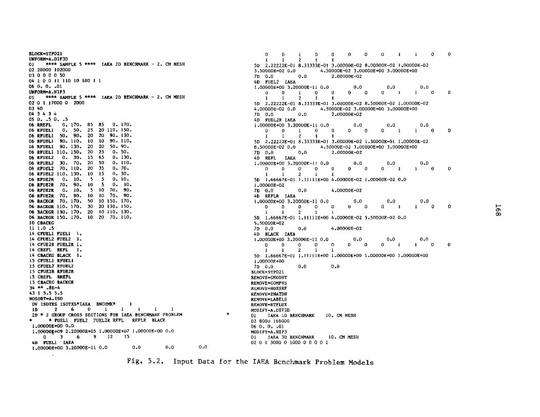
BLOCK-STPO21UNFORM-A.DIF3D01 **** SAMPLE 5 **** IAEA 2D BENCHMARK - 2. CM MESH02 20000 10200003 0 0 0 0 5004 1 0 0 11 110 10 100 1 106 0. 0. .01UNFORM-A.NIP301 **** SAMPLE 5 **** IAEA 2D BENCHMARK - 2. CM MESH02 0 1 17000 0 200003 4004 3 4 3 405 0. .5 0. .506 RREFL 0. 170. 85 85 0. 170.06 RFUEL1 0. 50. 25 20 110. 150.06 RFUEL1 50. 90. 20 20 90. 130.06 RFUEL1 90. 110. 10 10 90. 110.06 RFUEL1 90. 130. 20 20 50. 90.06 RFUEL1 110. 150. 20 25 0. 50.06 RFUEL2 0. 30. 15 65 0. 130.06 RFUEL2 30. 70. 20 50 0. 110.06 RFUEL2 70. 110. 20 35 0. 70.06 RFUEL2 110. 130. 10 15 0. 30.06 RFUE2R 0. 10. 5 5 0. 10.06 RFUE2R 70. 90. 10 5 0. 10.06 RFUE2R 0. 10. 5 10 70. 90.06 RFUE2R 70. 90. 10 10 70. 90.06 BACKGR 70. 170. 50 10 150. 170.06 BACKGR 110. 170. 30 20 130. 150.06 BACKGR 130. 170. 20 10 110. 130.06 BACKGR 150. 170. 10 20 70. 110.10 CBACKG11 1.0 .514 CFUEL1 FUEL 1.14 CFUEL2 FUEL2 1.14 CFUE2R FUEL2R 1.14 CREFL REFL 1.14 CBACKG BLACK 1.15 CFUEL1 IRFUELI15 CFUEL2 RFUEL215 CFUE2R RFUE2R15 CREFL RREFL15 CBACKG BACKGR34 ** .8E-443 1 5.5 5.5NOSORT-A.ISOOV ISOTXS ISOTXS*IAEA BNCHMK* 11D 2 6 0 1 1 1 1 12D * 2 GROUP CROSS SECTIONS FOR IAEA BENCHMARK PROBLEM
* * FUEL FUEL2 FUEL2R REFL REFLR BLACK1.00000E+00 0.01.00000E+09 2.20000E+05 1.00000E+07 1.00000E+00 0.0
0 3 6 9 12 154D FUEL I IAEA1.00000E+00 3.20000E-11 0.0 0.0 0.0
0 0 1 0 0 0 0 0 1 1 0 01 1 2 1 1
SD 2.22222E-01 8.33333E-01 3.00000E-02 8.00000E-02 1.00000E-023.50000E-02 0.0 4.50000E-02 3.00000E+00 3.00000E+007D 0.0 0.0 2.00000E-024D FUEL2 IAEA1.00000E+00 3.20000E-11 0.0 0.0 0.0 0.0
0 0 1 0 0 0 0 0 1 1 0 01 1 2 1 1
SD 2.22222E-01 8.33333E-01 3.00000E-02 8.50000E-02 1.00000E-024.00000E-02 0.0 4.5C7D 0.0 0.04D FUEL2R IAEA
1.00000E+00 3.20000E-11 0.00 0 1 0
0000E-02 3.00000E+00 3.00000E+002.00000E-02
00.0 0.0 0.0
0 0 0 1 1 0 01 1 2 1 1
5D 2.22222E-01 8.33333E-01 3.00000E-02 1.30000E-01 1.00000E-028.50000E-02 0.0 4.50000E-02 3.00000E+00 3.00000E+007D 0.0 0.0 2.00000E-024D REFL IAEA1.00000E+00 3.20000E-11 0.0 0.0
0 0 0 0 0 01 1 2 1 1
SD 1.66667E-01 1.11111E+00 4.00000E-021.00000E-027D 0.0 0.0 4.00000E-024D REFLR IAEA1.00000E+00 3.20000E-11 0.0 0.0
0 0 0 0 0 01 1 2 1 1
5D 1.66667E-01 1.11111E+00 4.00000E-025.50000E-027D 0.0 0.0 4.00000E-024D BLACK IAEA1.00000E+00 3.20000E-11 0.0 0.0
0 0 0 0 0 01 1 2 1 1
5D 1.66667E-01 1.11111E+00 1.00000E+001.00000E+007D 0.0 0.0 0.0
BLOCK-STPO21REMOVE-GEODSTREMOVE-COMPXSREMOVE-NDXSRFREMOVE-ZNATDNREMOVE-LABELSREMOVE-RTFLUXMODIFY-A.DIF3D01 IAEA -D BENCHMARK 10. CM MESH02 8000 16600006 0. 0. .01MODIFY-A.NIP301 IAEA 3D BENCHMARK 10. CM MESH02 0 1 3000 0 1000 0 0 0 0 1
0.0
0.0 0.00 0 1
1.00000E-02 0.0
1 0 0
0.0 0.00 0 1
5.50000E-02 0.0
1 0 0
0.0 0.00 0 1 1
1.00000E+00 1.00000E+00
0 0
Fig. 5.2. Input Data for the IAEA Benchmark Problem Models
00'

03 4404 3 4 3 4 4 405 XU .505 YU .505 ZL .505 ZU .506 RREFL 0. 170. 0 38 0. 170.06 RFUEL1 0. 50. 2 36 110. 150.06 RFUEL1 50. 90. 2 36 90. 130.06 RFUEL1 90. 110. 2 36 90. 110.06 RFUEL1 90. 130. 2 36 50. 90.06 RFUEL1 110. 150. 2 36 0. 50.06 RFUEL2 0. 30. 2 36 0. 130.06 RFUEL2 30. 70. 2 36 0. 110.06 RFUEL2 70. 110. 2 36 0. 70.06 RFUEL2 110. 130. 2 36 0. 30.06 RFUE2R 0. 10. 2 36 0. 10.06 RFUE2R 70. 90. 2 36 0. 10.06 RFUE2R 0. 10. 2 36 70. 90.06 RFUE2R 70. 90. 2 36 70. 90.06 RFUE2R 30. 50. 28 36 30. 50.06 RREFLR 0. 10. 36 38 0. 10.06 RREFLR 70. 90. 36 38 0. 10.06 RREFLR 0. 10. 36 38 70. 90.06 RREFLR 70. 90. 36 38 70. 90.06 RREFLR 30. 50. 36 38 30. 50.06 BACKGR 70. 170. 0 38 150. 170.06 BACKGR 110. 170. 0 38 130. 150.06 BACKGR 130. 170. 0 38 110. 130.06 BACKGR 150. 170. 0 38 70. 110.10 CBACKG11 1.0 .509 X 17 170.09 Y 17 170.09 Z 38 380.14 CFUEL1 FUEL 1.14 CFUEL2 FUEL2 1.14 CFUE2R FUEL2R 1.14 CREFL REFL 1.14 CREFLR REFLR 1.14 CBACKG BLACK 1.15 CFUEL1 RFUEL115 CFUEL2 RFUEL215 CFUE2R RFUE2R15 CREFL RREFL15 CREFLR RREFLR15 CBACKG BACKGR34-DELETE43-DELETE
Fig. 5.2. Input Data for the IAEA Benchmark Problem Models (contd.)

170
5.4.2 Storage Allocation Routines
The BPOINTER container allocation is done in a FORTRAN subroutine namedIGTLCM (with entry point IGTSCM). At individual installations there maybe special system routines available which could be called from IGTLCM toborrow space from the system or to return it. Programmers should look at
IGTLCM to see if modifications are in order.
5.4.3 TIMER
The subroutine TIMER is a general timing routine specified by the CCCC.The specifications for the subroutine include elapsed central processortime, remaining "limiting" time, elapsed peripheral processor time, currentdate, user identification, user account, user case identification and wallclock time. Many of these options are installation dependent so that they arenot implemented in the export version of TIMER. The options which are notimplemented are not required for execution of DIF3D although various timingedits are zeroed in the export version of TIMER. Programmers interestedin obtaining proper edits should modify TIMER according to local conventionsto implement the desired options.
5.4.4 GNIP4C Graphics
The graphics region map options in the GNIP4C input processor are not
operational in the NESC version of DIF3D; they are not crucial to the executionof the code, and graphics systems vary from system to system. An effort was
made, however, to make it as simple as possible to implement these options.
1. All graphics calls for the orthogonal geometry maps are made throughthe subroutine ORTPC2, and all graphics calls for maps of arrays ofhexagons are made through HEXPC5. It should be possible to limitcode modifications to these two routines.
2. The graphics map routines were coded and checked out for threedifferent graphics systems: CALCOMP, DISPLA and the local Argonnegraphics primitives. Code peculiar to CALCOMP and DISPLA werecommented out but are identified by comment cards of the form:
C**** DISPLA GRAPHICSor
C**** CALCOMP GRAPHICS
It should not be hard to reactivate the DISPLA or CALCOMP options.
3. On some systems additional, initialization calls may have to be made.
5.4.5 Random Access I/O Routines DOPC, DRED and DRIT
In the implementation of DOPC that accompanies the NESC package eachcode block using DOPC initializes it in their respective driver subroutines.On IBM systems DRED (DRIT) call REED (RITE) to perform asynchronous, randomaccess I/O. On CDC 7600 systems, the mass storage routines READMS, WRITMS,OPENMS and CLOSMS are used. On the CRAY-1 FORTRAN '77 I/O statements providerandom access capabilities. Installations with asynchronous, random accesscapabilities superior to those previously mentioned may simply replace DOPC,DRED, DRIT, CRED and CRIT. The latter two routines must be replaced ormodified to maintain ECM referencing consistent with any replacement DOPC
implementations.

171
ACKNOWLEDGEMENTS
A number of people have contributed significantly to the programming in
the DIF3D code package. C. H. Adams chiefly managed the evolution of theGNIP4C input processor from the FX2 input processor; the broader picture ofthe evolution of the CCCC routines was also greatly influenced by him.GNIP4C was touched by many others including B. J. Toppel, R. P. Hosteny,Herb Henryson II and several summer students. R. P. Hosteny coded the HMG4C
code block. The nodal solution option overlays are the work of R. D. Lawrence.
I am indebted to D. R. Ferguson who originally outlined the basic code
structure of DIF3D and chose the iteration strategies. Contributions to this
report were made by C. H. Adams, H. Henryson II, R. P. Hosteny and B. J.Toppel. Users whose feedback uncovered bugs during the development stages
are gratefully acknowledged. A. R. Hinds made several fine tuning suggestions
to improve the running times of the inner iteration kernal, SORINV, on the
IBM 370/195. Significant CPU time reductions were also achieved on the CDC7600 with a COMPASS assembler version of SORINV written by F. E. Dunn. For theassistance of L. Rudsinski with the implementation of DIF3D on the CRAY-1 at
NCAR, and F. Brinkley and D. McCoy on the CRAY-1 with CTSS at Los Alamos I amindebted. The work of Karen Leffler and Eileen Johnson in typing this report
is greatly appreciated.

172
REFERENCES
1. D. R. Ferguson and K. L. Derstine, "Optimized Iteration Strategies and
Data Management Considerations for Fast Reactor Finite DifferenceDiffusion Theory Codes," Nucl. Sci. Eng., 64, 593 (1977).
2. K. L. Derstine, "DIF3D: A Code to Solve One-, Two-, and Three-DimensionalFinite Difference Diffusion Theory Problems," ANL-82-64, Argonne NationalLaboratory, 1983.
3. R. D. Lawrence, "A Nodal Interface Current Method for Multigroup DiffusionCalculations in Hexagonal Geometry," Trans. Am. Nucl. Soc., 39, 461 (1981).
4. R. D. Lawrence, "A Nodal Method for Three-Dimensional Fast ReactorCalculation in Hexagonal Geometry," Proceedings of the Topical Meeting onAdvances in Reactor Computations, Vol. II, p. 1030, Salt Lake City,American Nuclear Society, March, 1983.
5. R. D. Lawrence, "The DIF3D Nodal Neutronics Option for Two- and Three-Dimensional Diffusion Theory Calculations in Hexagonal Geometry,"ANL-83-1, Argonne National Laboratory, 1983.
6. R. Douglas O'Dell, "Standard Interface Files and Procedures for ReactorPhysics Codes, Version IV", UC-32, Los Alamos Scientific Laboratory(September 1977).
7. B. J. Toppel, "The Fuel Cycle Analysis Capability, REBUS-3," ANL-83-2,Argonne National Laboratory, 1983.
8. R. W. Hardie and W. W. Little, Jr., "3DB, A Three-Dimensional DiffusionTheory Burnup Code," BNWL-1264, Battelle-Pacific Northwest Laboratories(1970).
9. D. R. Vondy, T. B. Fowler, and G. W. Cunningham, "VENTURE: A Code Blockfor Solving Multigroup Neutronics Problems Applying the Finite-DifferenceDiffusion-Theory Approximation to Neutron Transport," ORNL-5062, Oak RidgeNational Laboratory (1975).
10. W. R. Cadwell, "PDQ-7 Reference Manual," WAPD-TM-678, Bettis Atomic PowerLaboratory (1967).
11. D. R. Ferguson, Personal communication.
12. L. A. Hageman, "Numerical Methods and Techniques Used in the Two-Dimensiona Neutron Diffusion Program PDQ-5," WAPD-TM-364, Bettis AtomicPower Laboratory (1963).
13. L. A. Hageman and C. J. Pfeifer, "The Utilization of the Neutron DiffusionProgram PDQ-5," WAPD-TM-395, Bettis Atomic Power Laboratory (1965).
14. C. H. Adams, Personal communication. VARI3D performs perturbation theorycalculations and is still under development at Argonne.

173
15. C. H. Adams,"SYN3D: A Single-Channel, Spatial Flux Synthesis Code forDiffusion Theory Calculations", ANL-76-21, Argonne National Laboratory,1976.
16. T. B. Fowler, D. R. Vondy and G. W. Cunningham, "Nuclear ReactorCoie Analysis Code: CITATION," ORNL-TM-2496, Oak Ridge NationalLaboratory, Tenn. (1971).
17. T. A. Daly et al., "The ARC System Two-Dimensional Diffusion TheoryCapability, DARC2D," ANL-7716, Argonne National Laboratory (1972).
18. R. S. Varga, Matrix Iterative Analysis, Chap. 3, Prentice-Hall, Inc.,Englewood Cliffs, New Jersey (1962).
19. A. F. Henry, Nuclear Reactor Analysis, Cambridge, Mass. (1975).
20. E. L. Wachspress, Iterative Solution of Elliptic Systems and Applicationsto the Neutron Diffusion Equations of Reactor Physics, Chap. 2.,Prentice-Hall Inc., Englewood Cliffs, New Jersey (1966).
21. R. S. Varga, Proc. Symp. Appl. Math., 11, 164, American MathematicalSociety, Providence, Rhode Island (1961).
22. G. Birkhoff and R. S. Varga, J. Soc. Ind. Appl. Math., 6, 354 (1958).
23. R. Froehlich, "A Theoretical Foundation for Coarse Mesh VariationalTechniques," Proc. Int. Conf. Research Reactor Vitalization and Reactor
Mathematics, Mexico, D.F., 1, 219 (May 1967).
24. E. L. Wachspress, Iterative Solution of Elliptic Systems and Applicationsto the Neutron Diffusion Equations of Reactor Physics, pp. 77-80, 83 and270-287, Prentice-Hall Inc., Englewood Cliffs, New Jersey (1966).
25. D. A. Flanders and G. Shortley, J. Appl. Phys., 21, 1326 (1950).
26. R. S. Varga, Matrix Iterative Analysis, Chap. 5, Prentice-Hall, Inc.,Englewood Cliffs, New Jersey (1962).
27. R. S. Varga, Matrix Iterative Analysis, Chap. 4, Prentice-Hall, Inc.,Englewood Cliffs, New Jersey (1962).
28. B. J. Toppel, C. H. Adams, R. D. Lawrence, H. Henryson II, and K. L.Derstine, "Validation of Alternative Methods and Data for a BenchmarkFast Reactor Depletion Calculation," Proceedings of the Topical Meetingon Advances in Reactor Physics and Core Thermal Hydraulics, (held inKiamesha Lake, NY), NUREG/CP-0034, Vol. 1, p. 177, U.S. NuclearRegulatory Commission, Washington, D.C., August 1982.
29. R. S. Varga, Matrix Iterative Analysis, Chap. 6, Prentice-Hall, Inc.,Englewood Cliffs, New Jersey (1962).
30. R. S. Varga, Matrix Iterative Analysis, Chap. 9, Prentice-Hall, Inc.,Englewood Cliffs, New Jersey (1962).

174
31. I. Stakgold, Boundary Value Problems of Mathematical Physics, Vol. I,pp. 79-81, MacMillan, Toronto (1969).
32. E. Isaacson and H. B. Keller, Analysis of Numerical Methods, Chap. 2,Wiley, New York, 1966.
33. M. R. Wagner, "GAUGE - A Two-Dimensional Few Group Neutron Diffusion -Depletion Program for a Uniform Triangular Mesh," GA-8307, Gulf GeneralAtomic, 1968.
34. D. A. Meneley, "Acceleration of External Source Problems in Near-CriticalSystems," Applied Physics Division Annual Report: July 1, 1970, to June30, 1971, ANL-7910, pp. 513-515.
35. E. Issaacson and H. B. Keller, Analysis of Numerical Methods, pp. 98-102,Wiley, New York (1966).
36. L. C. Just, H. Henryson II, A. S. Kennedy, S. D. Sparck, B. J. Toppeland P. M. Walker, "The System Aspects and Interface Data Sets of theArgonne Reactor Computation (ARC) System," ANL-7711, Argonne NationalLaboratory (1971).
37. G. E. Bosler, R. D. O'Dell, and W. M. Resnik, "LASIP-III, A GeneralizedProcessor for Standrd Interface Files," LA-6.80-MS, Los Alamos Scientific
Laboratory (1976).
38. H. Henryson II, B. J. Toppel, and C. G. Stenberg, "MC2-2: A Code toCalculate Fast Neutron Spectra and Multigroup Cross Sections," ANL-8144,Argonne National Laboratory (1976).
39. M. K. Drake, ed., Data Formats and Procedures for the ENDF NeutronCross Section Library, Brookhaven National Laboratory, BNL 50274(Oct. 1970).
40. H. Henryson II, Personal communication.
41. C. H. Adams, K. L. Derstine, H. Henryson II, R. P. Hosteny and B. J.Toppel, "The Utility Subroutine Package Used by Applied Physics ExportCodes," ANL-83-3, Argonne National Laboratory, 1983.
42. L. Rudsinski, "Production Runs on the CRAY-1," ANL-79-68, Argonne NationalLaboratory (1979).
43. D. Boley, B. Buzbee, and S. Parter, "On Block Relaation Techniques,"University of Wisconsin, Mathematics Research Center Report 1860 (June1978).
44. D. Boley, "Vectorization of Block Relaxation Techniques: Some NumericalExperiments," Proceedings of the 1978 LASL Workshop on Vector and ParallelProcessors, LA-7491 (September 1978).
45. K. L. Derstine, "An Experience with the Conversion of the Large-ScaleProduction Code DIF3D to the CRAY-1," Scientific Computer InformationExchange 'Meeting, Livermore, CA, pp. 116-127 (September 1979).

175
46. G. Buckel, K. Kufner, and B. Stehle, "Benchmark Calculations for aSodium-Cooled Breeder Reactor by Two- and Three-Dimensional DiffusionMethods," Nucl. Sci. Engr. 64, 75 (1977).
47. "Benchmark Problem Book," ANL-7416, Supplement 3, Argonne NationalLaboratory, to appear, 1984.
48. "Benchmark Problem Book," ANL-7416, Argonne National Laboratory (1968).

Appendix A
ARCSPO21 INSTREAM JCL PROCEDURE FOR IBM 370 SYSTEMS
/ARCSFO2I PROC ATCYL-5,ATDSP=' ( ,ELETE)' ,ATFLUX-'&ATFLIIX',ATVOL=,DEST='*',DEST2-F,DMPDEST-F,DMYICYL-21,DMY2CYL-7,DMY5CYL-4,FDCCYL=20,FLXCYL=1,HALFTRK-6136,ISOCYL-I,ISODSP''(MOD,KEEP)',ISOVOL-,
// ISOTXS-'&ISOTXS' ,MODEDCB-'RECFM-U',MODLIBl-'SYSl.DUMMYLIB',MODLIB2-'Cl16.NESC.MODLIB',NACYL-5,NADSP-'( ,DELETE)' ,NAFLUX-'&NAFLUX' ,NAVOL-,NHCYL-5,NHDSP-'(,DELETE)',NHFLUX-'&NHFLUX',NHVOL=,PATH-'STPO21',POSTLIR-'SYSI.DUMMYLIB',PRELI8-'SYS.DUMMYLIB',PSICYL=55,PSUCYL=3,QRTRTRK=3064,RECN-1000K,RTCYL-5,RTDSP-' (,DELETE)' ,RTFLUX-'&RTFLUX',RTVOL.,TIMLIM='(600,0)',TWELTRK-1016,SRFCYL-12,UNITS-BATCHDSK,UNITSCR=SASCR,ZONCYL-1
/* *****************************a*********************************
//* *CATALOGED PROCEDURE FOR 1, 2 OR 3D DIFFUSION CODE DIF3D 3.0 *
*LAST MODIFIED 6/09/83, PREVIOUSLY MODIFIED 5/16/83/* ** *
***************************************************************a
/* *******************************************************************
* PARAMF.ER DEFAULT VALUE USAGE FTNNFOO 1
/* PATH STPO21 PROGRAM NAME EXEC* TIMLIM (600,0) STEP TIME LIMIT EXEC
//* RECN 1000K STEP REGION SIZE EXECf MODLIB! SYSI.DUMMYLIB SECOND STEP LIBRARY STEPLIF
/* MODLIB2 C116.NESC.MODLIB NESC SYSTEM LIBRARY STEPLIF* PRELIR SYS1.DUMMYLIB FIRST STEP LIBRARY STEPLIF
/* POSTLIB SYS1.DIIMMYLIB LAST STEP LIBRARY STEPLIE* DF.ST * OUTPUT DEST. (PRINTER) 06
/* DEST2 F OUTPUT DESTINATION FICHE 10/* OMPOEST F ROUTE DUMP TO FICHE SYSU l
//a ATC.YL 5 NO. OF CYL. FOR ATFLUX 31//a ATDSP (,DELETE) DISPOSITION OF ATFLUX 31
//* ATFI.IIX &ATFI.I(X DSN FOR DATASET ATFI.ITX 31
/* ATVOI. ------ VOI.lUMF FOR ATFI.1'X 31//* ISOCYI. I NO. CYL. FOR ISOTY.S 27
//*
/1*//*//*//*
//*//*//*//*
//*
//*
//*
//*
//*
//*
//*
//*
//* a
I S I)SI'IS (TXt
NA1)SI'NAFl.1'NNAV(1.NIICYI.NIIhS)'NI1FI.l'XN5I.1.
RTCYI.RT)S I'PTF"I.I'XPTVOI1.SRFCY I.
(MonKEEP)&ISOTXS
( , l..FTE)hNAFI.I'X
( ,IFI.ETE)
SNH Fl (TX
(,IIFI.ETE)
&RTFI.liX
12
DISPOSITION OF ISOTXSOSN FOR (ATASFT ISOTXSVOI.T'ME FOR ISOTXS0iS'OSITION OF NAFI.IIX
((SN FOR NAFI.I;XVOLITME FOR NAFI.IIXNO. OF CYI.. FOR N1FI.l'XDISPOSITION ('F N .FIOX
(SN FOR NIIFI.XVOLUME FOR NIIFLIXNO. OF CY.. FOR RTFLIUX
DISPOSITION OF RTFI.I'X(SN FOR DATASET RTFI.!X
VOLUME FOR RTFI.IIXNO. OF CYL. FOR SURF. FLUXES
'727272424242323232330
3031)
66,67
TIF FOL..OWING FIVE PARAMF.TERS DF.FINF. CYL.INDER AL.LOCATI((NAND T(IE DCH FOR AIIXILIARY FLUX, FDCOF.F AND 7.ONMAP IIATASFTS
/ FI.XCY1.//* M((DE(CBR//a PSICYI.
// ;'.NCYI.
//*
/ / *
f/*
/ !//*
//*//*
/1*//*//*//*
//*//*
S/ *
//*
B
BB
MP
20
RECFM-1I
5'1
NO. OF CYL. FOR FDCOF.F DATASET 45NO. CYL. FOR I GR OU'P FIX FII.FS46-49,51 ,55,DCR FOR MA.IOR 10 IDATASETS 41,52,55,56
NO. CYL. FOR FI.t'X DATASETS 41-42,54NO. CYL. FOR A.. ITPSCAT Fl.I'X 43NO. CYI. FOR 7.ONMAP 52
T((F F(TI.I.OWI N). THREE PARAMETERS ((F.F1 NE CYI. I N(ER AIl..CATI (N
FOR DI'MMY FIlES WHICH AlI.ICATE CONTTGIIOITS BL.OCKS OF SPACETO BE m"TBAI.I.(CATEI TO VARIOUS SCRATCH DATA SETS.
I(MYICYI.DMY2CYi.
DMYSCYI.
217
NO. ((F CYL. FOR FI(CI(FF, 7.ZNMAP
NO. OF CYL. FOR FlUA'X (ATASFTS(42,47,56)
NO. OF CYL.. FOR FL.IX DATASETS
45,52
(41 .46,55)(4x,51,54)(41,49)
TIE FOLLWING SIX PARAMFTFRS DEFINE UiNIT AND BI.KSI.E FOR
A VARIETY ((F ((ATASETS
((AI.FTRK"HTPTRK
TW*: I.TRK'NI I
('N T R
613631()4
(((16RATH(:DI(SKSASCR
(AL.F TRACK HI.((CKIN(CARTERER TRACK HI.((CK I NC
TWElFTH TRACK B!.OCKIN((:ENER I(C ('N IT NAMF(:ENERIC ('NIT NAME
// I '.' ( (CM-4PAT(I,TIMF.-&TIMI.IM,RF.GION-&RPEN/ /ST 1r). H N- T(R( H F1. I , T l PI -/ /)I) N( T(SN- M((OI. I B I . I'/ / I)! ((SN-hM((l(I. I B:',I) 11SI-SR/ I)I) OSN-PO(STI.I , S* -SI
F

//DUMMYI fn DSN-&&DUMMYl,SPACE(CYL,(&DMYICYL,1),,CONTIG),// UNIT-&UNITSCR// SHARED BY FDCOEF(45) ,ZONMAP(52)//nDLMMY2 DD DSN=&&DUMMY2,SPACE-(CYL,(&DMY2CYL,1),,CONTIG),// UNIT-(&UNITSCR,SEP-(DUMMY1))// SHARED BY PSIOLD(41),PSIGO(55),FRNOLD(46)//n1IMMY3 nn DSN=&&DIIMMY3,SPACEF(CYL,(&DMY2CYL,1) ,,CONTIG),// UNIT=(&UNITSCR,SEP-(DUMMY1,DUMMY2))
SHARED BY PSINEW(42),PSIGN(56),FRNNEW(47)//DTUMMY4 DI DSN=&&DUMMY4,SPACE-(CYL,(&DMY2CYL, 1), ,CONTIG) ,
UNIT-(&INITSCR,SEP-(DUMMYl,DUMMY2,DUMNY3))SHARED BY FRNMI(48),SRCNEW(51),FSRC(54)
//DlMMYS DD DSN-&&DUMMY5,SPACE.(CYL,(&DMY5CYL,1),,CONTIG) ,UNIT-(&UNITSCR,SEP-(DUMMYI,DUMMY2,DUMMY3,DUMMY4))SHARED BY FRNN2(49),PSIUP(43)
//FTO5FOO! ID DDNAME-SYSINBCD INPUT.
//FTO6FOOI DD SYSOUT-&DEST,DCB-(RECFM-FBA,LRECL133,BLKSIZE-1596)PRINTED OUTPUT.
//FTO9FOO1 D)D IINIT-&UNITSCR,SPACE-(CYL,(1 ,1)),DCB-(RECFMNVBS,LRECL-B4,BLKSIZE=&QRTRTRK)ARC SYSTEM SPOOLED OUTPUT.
//FT1OFOO1 D) DCB=(RECFM=FBA,LRECL-133,BLKSIZE-1596),SYSOUT=&DEST2// ALTERNATE PRINT FILE.//*/*h
/1*DATASETS 11 TO 17 ARE MODULE DEPENDENT BCD DATASETS
lIFTI1FOi DD DSN=&&ADIF3,. iT-&UNITSCR,SPACE-(TRK,(1 ,5)),DCB-(RECFM-VBS,LRECL=84,BLKSIZE-&TWELTRK)
/I 1,2 OR 3D DIFFUSION MODULE DEPENDENT BCD DATASET.//FTI2FOO1 DD DSN-&&ANIP3,UNIT=&UNITSCR,SPACE-(TRK,(4,1 )),// DCB-(RECFM-VBS,LRECLR84,BLKSIZE-&QRTRTRK)
// THE ARC SYSTEM GENERAL NEUTRONICS BCD DATASET.//FTI3FOO1 DD DSN-&&AHMG4C,.INIT-&UNITSCR,SPACE-(TRK,(1,0)),// DCB-(RECFM-VBS,LRECL=84,BLKSIZE-&TWELTRK)// CCCC HOMOGENIZATION MODULE DEPENDENT BCD DATASET.//FT1SFOO1 DD DSN-&&AISO,UNIT-&UNITSCR,SPACE-(CYL,(1 ,1)),
DCB-(RECFM-VBSLRECL=84,BLKSIZF.-QRTRTRK)THE ISOTXS BCD DATASET.
//*DATASETS 18 TO 25 ARE MODULE DEPENDENT BINARY DATASFTS.
1*//FTIRFO1 DI)D DSN-&DTF3D,UNIT&IUNITSCR,SPACE-(TRK,(1,O)),
DCB-(RECFM-VBS, LRECI.-X , RLKSI ZF.=&ORTRTRK)1 , 2 OR 3D DIFFUSION MODULE DEPENDENT BINARY DATASFT.
//FTl9FO1 DD DSN=&&COMPXS,UNIT-&UNITSCR,1SPACE-(CYL,(1,1)),IDCB-(RECFM=VBS,LRECL=X ,RLKSIZE-&1HA1.FTRK)
// COMPOSITION MACROSCOPIC CROSS-SECTION DATASET.//FT2OFf1 DD DSN-&&LABF.LS,UNIT=&UNITSCR,SPACF=(TRK,(3,O)),
'/DCB-(RF.CFMVBS,LRE.CL-X,RLKSI7.E=&TWELTRK)
// A.NTP3 LABELS AND AREA DEFINITIONS./FT22FO(O fin DSN-&D3F.DIT,ITNIT-&IJNITSCR,SPACE-(CYL,(1,1)),
1)CR(RF.CFM-VBS,LRECL=X,BLKSIZE&-HALFTRK)// DIFID EDITS INTERFACE DATASET.
//FT23FOOl PD DSN-&NHFLIX,DISP=&NHDSP,SPACE-(CYL,(&NHCYL,1)),X // UNIT-&UNITS,VOL=SER-&NHVOL,
// DCB-(RECFM-VBS,LRECL-X,BLKSIZE=&HALFTRK)// RESTART FILE FOR REAL NODAL HEX CALCULATION.
X //FT24FOOI D DSN-&NAFLUX,DISP-&NADSP,SPACE-(CYL,(&NACYL,1)),// UNIT=&UNITS,VOL-SER-&NAVOL,// DCB-(RECFM-VRS,LRECL-X,BLKSIZE-bHALFTRK)
X // RESTART FILE FOR ADJOINT NODAL HEX CALCULATION.//FT25FOO1 DD DSN-&PKEDIT,UNIT-&IJNITSCR,SPACE-(CYL,(1,I1)),// DCB-(RECFM-VBSLRECL-X,BLKSIZE-bHALFTRK)
X // PEAK POWER DENSITY AND FLUX INTERFACE DATASET.//*//* DATASETS 26 TO 40 ARE CCCC INTERFACE FILES.
X //*//FT26FOO1 DD DSN-&GEODST,UNIT-&UNITSCR,SPACE-(CYL,(01,1)),
X // DCB-(RECFM-VBS,LRECL-X,BLKSTZE-bHALFTRK)// CCCC GEOMETRY DESCRIPTION DATASET.
X //FT27F001 D) DSN-&ISOTXS,DISP-&ISODSP,SPACE=(CYL,(&ISOCYL,1)),// UNIT-&LUNITS,VOL-SER-&ISOVOL,// DCB-(RECFM-VBS,LRECL-X,BLKSIZE-&HALFTRK)
X // CCCC NUCLIDE-ORDERED MICROSCOPIC CROSS SECTIONS.//FT28F001 DD DSN-&NDXSRF,ITNIT-&bUNITSCR,SPACE(TRK,(03.,)),
X // DCB-(RECFM-VBS,LRECL-XRLKSIZE&bHALFTRK)// CCCC NIUCLIDE/CROSS SECTION REFERENCING DATA.//FT29FOO1 DD DSN-&ZNATDN,UNIT-&UINITSCR,SPACE(CYL,(01.1)),
/ DCR-(RECFM-VBS,LRECL-X,BLKSIZE-bHALFTRK)// CCCC ZONE NUCLIDE ATOM DENSITIES.//FT3OFOO1 DD DSN-&RTFLUX,DISP-&RTDSP,SPACE-(CYL,(&RTCYL,1)),
X // UNIT-&UNITS,VOL-SER-&RTVOL,// DCR-(RECFM-VBSLRECL-X,BLKSIZE-bHALFTRK)// CCCC REAL FLUX INTERFACE DATASET.
X //FT3IFOO1 nn DSN-&ATFLUX,DISP-&ATDSPSPACE-(CYL,(&ATCYL,1)),// UNIT-&UNITS,VOL-SER-&ATVOL,// DCB-(RECFM-VBS,LRECL-X,BLKSIZEbHALFTRK)
X // CCCC ADJOINT FLUX INTERFACE DATASET.//FT32FOO1 DD DSN-&FTXSRC,1INIT-&IINITS,SPACE-(CYL,(O1,1)),// DCB-(RECFM-VBS,I.RECI.-X,BLKSIZE-bHALFTRK)
X // CCCC FIXED SOURCE DATASET.//FT33FOO1 DD DSN-&RZFIUX,UNIT-&UNITSSPACE-(TRK,(O1 ,1)),
// DCR-(RECFM-VBS,LRECL-XBLKSIZF.&HALFTRK)// CCCC ZONE AVERAGED FLUX INTERFACE DATASET.//FT34FOOIfDD DSN-&PWDINTIINIT-&UNITS,SPACE-(CYI.,(Ol.1)),// DCR-(RECFM-VBS, LRECL-X , BI.KSTZF.-&HALFTRK)
X // CCCC POWER DENSITY INTERFACE DATASET.//FT39F001 DD DSN=&SEARCH,IINIT-6UNITSCR,SI'ACF-(TRK,(03,O)),// DCR-(RECFM-VBSLRECL-X,BLKSIZE-&HAI.FTRK)
X // CCCC CRITICALITY SEARCH DATA.//*//* DATASETS 41 TO 60 ARE SCRATCH DATASFTS.
X//
//FT41F001 DI) DSN-&&PSIOLD,SIUBALLOC-(CYL,(&PSICYL,l ),DIMMY2),// DCB-&MODEI)CR
X // FLUX ITERATE SCRATCH 1)ATASET.//FT42FOOIfDD DSN=&&PSINEW,SlJBALLOC-(CYL,(&PSICYL,),)IIMMY3),
X
X
X
X
Na

//
//FT43F l
//FT43F001//
//FT65F001
//FT7 O
//
I r6F001
/FT47F001
f/ FT4S FOO 1
fFTI6F001
/FTS 3FO 1
FTS2F00O//"
// F53F001
//"
//FT fO
// T7Fn
/ / FT8FN
//FT4SFOO1
/ / Fr(n
//FTS IFO01l
//*//FTS3FO01
FT7FOOI
FTS9FOOI
IFT76FO1 I
DCB-MNODEDCRFLUX ITERATE SCRATCH DATASET.
DD DSN-& PSIUP,SURALLOC-(CYL,(&PSUCYL,I),DUMMY5),DCB-MODEDCBAIIXILIARt FLUX DATASET FOR ADJOINT UPSCATTER ITERATIONS
DD DSN-&&FDCOEF,SUBALLOC-(CYL,(&FDCCYL,5),DUMMYI),DCB-&MODEDCBFINITE DIFFERENCE COEFFICIENTS SCRATCH DATASET.
DD DSN-&FRNOLD,SUBALLOC-(CYL,(&FLXCYL, I ),DUMMY2),DCB-6MODEDCBFISSION SOURCE SCRATCH DATASET
DD DSN=&LFRNNEW,SIIRALLOC-(CYL,(&FLXCYL,1) ,DUMMY3),DCB-IMODEDCBFISSION SOURCE SCRATCH DATASET
DD DSN-iFRNMI,SUBALLOC-(CYL,(&FLXCYLI,1) ,DUMMY4),DCB-&MODEDCBFISSION SOURCE SCRATCH DATASET.
DO DSN-W&FRNM2,SUBALLOCa(CYL,(&FLXCYI ,1),DUMMY5),DCR-&MODEDCRFISSION SOURCE SCRATCH DATASFT.
DD DSN.&&SRCNEW,SUBALLOC-(CYL,(&FLXCYL,1),DUMMY4),DCB-MODEDCRTOTAL SOURCE SCRATCH DATASET.
DD DSN-&&ZONMAPSUBALLOC-(CYL,(&ZONCYL, I),DUMMYI),DCB-nMODEDCRZONE MAP SCRATCH DATASET.
OD DSN-&&CXSECT,UNIT-&UNITSCR,SPACE YL,(OI,1)),DCR-&MODEDCB
COMPOSITION CROSS SECTIONS SCRATCH DATASET.DV DSN-&FSRC,SUBALLOC-(CYL,(&PSICYL, I) ,DUMMY4),
DCB-MODEDCBFIXED SOURCE SCRATCH DATASET.
DO DSN-& PSIGOSUBALLOC-(CYL,(&FLXCYL,l1) ,DUMMY2),DCB-&MODFDCBFLUX ITERATE SCRATCH D.TASET ONE GROUP.
DD DSN=u&PSICN,SJBALLOC-(CYL,(&FLXCYL,1),DUMMY3),DCB-MODEDCBFLUX ITERATE SCRATCH DATASET ONE GROUP.
DATASETS 66 TO 71 ARE SCRATCH DATASETS
DI DSN-&SCROOl ,INIT-UNITSCRSPACE-(CYL.,(&SRFCYL,2)),
DCR-(RECFM-VRS, LRECL-X , LKS TZE-&HALFTRK)SCRATCH FILE I.
DI) DSN-6SCRf02,UNIT-eUNITSCR,SPACE-(CYI, (&SRFCYL.,2)),DCR-(RECFMVBS,LRECL-X , BLKSIZE6&HALFTRK)SCRATCH FILE 2.
DO DSNm6SCR003,UNIT-&UNITSCRSPACE(CYL,(O1,1)),DCR-(RECFM-VRSLRECL-XBLKSIZE-&HAI.FTRK)SCRATCH FT I..E 3.
DO DSN-&SCROO4 ,UNIT-&UNITSCRSPACE-(CYL,(O ,1)),DCR-(RECFM-VRS, LRECL-X ,RLKS1ZE-&HAI.FTRK)SCRATCH FILE 4.
DO DSN-&SCROO5,UNIT-.&UNITSCR, SPACE-(CYL, (O l ,1)).9
x //////FT71FOO1
X ///// /*
X //*/ /*/ /FT76FOO
X //I
//FT77FOO1
X //
//FT78FOO1
X //
//FTROFOOIX //1
/// /SYSITDIJMP
X //f//
W1"
X
X
X
X
X
X
DCB-(RECFMV RS,LRECL-XBLKSIZE.&HALFTRK)SCRATCH FILE 5.
DD DSN-&SCR006,UNIT-&UNITSCR,SPACF.=(CYL,(01 ,1)),
DCB=(RECFM-VBS,LRECL-XBLKSIZE-&HALFTRK)SCRATCH FILE 6.
DATASETS 76 TO 80 ARE UDOIT INTERFACE DATASETS
DD DSN-&UDOITI ,UNIT-&UNITSCRSPACE-(CYL,(01 ,1)),DCR=(RECFM-VBS,LRECL=X , BLKSIZE-&HA'FTRK)UDOIT INTERFACE FILE VERSION 1.
DD DSN-&IDOIT2,UNIT=&UNITSCR,SPACE-(CYL,(O1 ,1)),DCR=(RECFMiVBS,LRECLmX,BLKSIZE-&HALFTRK)UDOIT INTERFACE FILE VERSION 2.
DD DSN-&UDOIT3,UNIT.&UNITSCR,SPACEm(CYL,(O1 ,1)),DCB-(RECFM-VBS,LRECL-X,BLKSIZI?-&HALFTRK)UDOIT INTERFACE FILE VERSION 3.
DD DSNmAUDOIT,UNIT=UNITSCR,SPACE=(TRK,(3,,1)),DCB=(RECFM=VBSLRECL-84 , BLKSIZE-&QRTRTRK)BCD INPUT DATASET FOR UDOIT MODULES.
DD SYSOUT=&DMPDESTSYSTEM DUMP DATASET FOR ABNORMAL JOB TERMINATION.
PEND
X
X
X
x
X
x
X

Appendix B
DIF3D BCD INPUT FILE DESCRIPTIONS
B.1 A.DIF3DCI)C'l)CI)Ch'(:nC1)
CnCDCDCr)
CDCDCT)
CDC
REVISED 12/15/82 -
A.DIF3D -ONE-, T)-, AND THREE-9IMENSIONAL DIFFUSION THEORY -NODULE-DEPENDENT BCD INPUT
THIS BCD DATASET MAY BE WRITTEN EITHER -IN FREE FORMAT (UNFORM-A.DIF3D) OR -ACCORDING TO THE FORMATS SPECIFIFD FOR EACH -CARD TYPC (DATASET-A.D F3D). -
COLUMNS 1-2 MUST CONTAIN THE CARD TYPE NUMBER. -
A BLANK OR ZERO FIELD GIVES THE DEFAULT OPTIONINDICATED. -
NON-DEFAULTED DATA ITEhS ON THE A.lIF3D -DATA SET ALWAYS OVERRIDE THE CORRESPONDING -DATA ON THE RESTART DATA SET DIF3D. -
C******* *0******************************************
CR PROBL M TITLE (TYPE 01) -C -CL FORMAT---(12,4X,11A6) -C -CD COLUMNS CONTENTS...IMPLICATIONS, IF ANY -CD =in==mm--- in- - - - - - - - - - - --======--=== ====== ==-
CD 1-2 01 -CDCD 7-72 ANY ALPHANUMERIC CHARACTERS (1 CARD ONLY). -CC
1-: 02
7-12 POINTR CONTA NER ARRAY SIZE IN FAST CORE MEMORY (FCM)
IN REAL WORDS (DEFAIULT-10000).
13-IA POTNTR CONTAINER ARRAY SI7.E IN rXTENDF.D COREMEMORY (ECM) TN REAI.*R WORTS (D.FAILT-30000).
19-24 POINTR DERIGGING EDTT.0...NO DEBIICGTNC PRINTOUT (DEFAlIU T).1...DF.RI'CCING DUMP PRTNTOlIT.2...DF.R'C.TNC TRACE I RINTOUT.I... ROTH DUMP AND TRACE PRINTOUT.
.-------------.... --...--.------.---------
C**CCCFCrCECECM
C.'C0CSCmCM
cmC
CN
C
STORAGE AND DUMP SPECIFICATIONS (TYPE 12)
FORMAT-----(I2.4X.31TA)
CMII'"'4S CONTENTS...IMPLICATTONS, TF ANY
PROBLEM CONTROl. PARAMETERS (TYPE 03) -
FORMAT-----(T2,4X,11Ih)
COl.u1MNS CONTENTS... IMPLICATIONS, IF ANY -
1-2 03 -
7-12 PROBLEM TYPE. -0. . .K-FFFFC iiVE PROBLEM DEFAULTT).1...FIXED SOURCE PROBLEM. -
11-iM SOLITTION TYPE. -
0...REAI. SOL.IUTION (DEFAII.T). -I... AD.JOINT SOI.lJTION. -2... ROTH REAl. AND AD.IOINT SOLUTION. -
19-24 C.IERYSHEV ACCELERATION OF OlITER ITERATIONS. -0...YES, ACCELERATE T1F OITER ITERATIONS (DEFAIIT). -I...N) ACCEI.ERATION. -
2S-31) MINIMuM PL.ANE-IL.OCK (RECORD) SIZE IN RFAI.*M WORDS FOR -I/O TRANSFER IN THE CONCURRENT INNER ITERATION -STRATE(:Y. THE DEFAULT (-4 SOO) S IIl GHLY RECOMMENDED. -
31 -3h OUTER ITERATION CONTROL..-
-1... BYPASS l)TFII) MODIII.E.--2... CAI.C I1.ATE DATA MANA(:EMENT PARAMETERS AN) PERFORM -
NElITRONICS EDITS ONL.Y. --I ... CAI.CIII.ATF DATA MANAGEMENT PARAMETERS, CAI.ClIl.ATE -
OVERREI.AXATION FACTORS AND 'ERFORM NEUITRONICS -
CRCCI.CCD'T)
CDCI)CI)CD
CI'
CI)CD,n
CI)CDCI)CDC1)CI)Cl'
Cl)(:11Cl)CD
CI)CI)CI)(:1)Cl)CI)
1-r
CaCC.CCI)

CDCDCDCDCDCDCDCDCDCDCDCDCDCDCDCDCDCDCDCDCDCDCDCDCDCDCDCDCCMCMCmCrCmCmCMCmCMCMCMCMCMCmCmCMCMCMCmCMCMCMCMCMCM
OR
EDITS ONLY. -.CE.0...MAXIMUM NUMBER OF OUTER ITERATIONS (DEFAULT-30).
37-42 RESTART FLAG.0...THIS IS NOT A RESTART (DEFAULT). -
1...THIS IS A RESTART PROBLEM. -
43-4A JOB TIME LIMIT, MAXIMUM (CP AND PP(OR WAIT)) PROCESSOR -SECONDS (DEFAULT-1000000000). -
49-54 NUMBER OF UPSCATTER ITERATIONS PER OUTER ITERATION -(DEFAULT-5). PERTINENT TO UPSCATTER PROBLEMS ONLY. -
55-60 CONCURRENT ITERATION EFFICIENCY OPTION. -0...PERFORM THE ESTIMATED NO. OF INNER ITERATI'ONS FOR -
EACH GROUP.1...AVOID THE LAST PASS OF INNER ITERATIONS IN THOSE
GROUPS FOR WHICH THE NO. OF ITERATIONS IN THE LASTPASS ARE LESS THAN A CODE DEPENDENT THRESHOLD. -
61-66 ACCELERATION OF OPTIMUM OVERRELAXATION FACTOR -CALCULATION.0...NO ACCELERATION (DEFAULT). -1...ASYMPTOTIC SOURCE EXTRAPOLATION OF POWER ITERATIONS-
USED TO ESTIMATE THE SPECTRAL RADIUS OF EACH INNER -(WITHIN GROUP) ITERATION MATRIX. -
67-72 OPTIMUM OVERREIAXATION FACTOR ESTIMATION ITERATION -CONTROL. THE DEFAULT (-50) IS STRONGLY RECOMMENDED. -
THE MAXIMUM NUMBER OF OUTER ITERATIONS SENTINELSPECIFIES THE NUMBER OF OUTERS THAT CAN BE PERFORMED -(COLS. 31-36) EACH TIME THE DIF3D MODULE IS INVOKED. -
THE DIF3D TERMINATION PROCEDURE WILL ALWAYS: -1...(RE)RITE THE APPROPRIATE FLUX FILES -
(PTFLITX OR ATFLUX). -2...(RE)WRITE THE RESTART FILE DIF3D. -
TO FACILITATE AUTOMATIC RESTART. THE RESTART FLAG -ON THE DIF3D RESTART CONTROL FILE WILL BE TURNED ON -AUTOMATICALLY UPON DETECTION OF: -
1...MAXIMUM NUMBER OF OUTER ITERATIONS. -2...TIME LIMIT. -
TO RESTART THE FLUX CALCULATION: -EITHER -
PROVIDE THE RESTART DATA SET DIF3D ANDTHE APPROPRIATE FLUX DATA SET (RTFLlIX OR ATFLIIX)AND SPECIFY THEM TINDER "BLOCK-OLL" IN THE BCDINPIT DATA
1...SET THE RESTART FLAG (COLS. 37-42) TO 1 ONTHE TYPE 03 CARD. THIS PERMITS IMMEDIATE
CNCNCNCNCNCNCNCNCN
CNCNCNCNCNCNCNCNCNCNCNCNCNCNCNCNCNCNCNCNCNCNCN
CUM
CNC
C--
CRCR
CL
CCDCDCT)CDCDCI)CDC)C)CD
COLUMNS
1-2
7-12
CONTENTS...IMPLICATIONS, TF ANY
04n4 -
PROBLEM DESCRIPTION EDIT (IN ADDITION TO USER TNPUlT -
SPECIFICATIONS WHICH ARE ALWAYS EDITED. -C...NO EDITS (DEFAULT). -1...PRIN? EDITS. -2...WRITE EDITS TO AUXILIARY OUTPUTT FILE. -3.. .WRITE EDITS TO BOTH PRINT AND AUXILIARY OUTPUT FILE-
RESUMPTION OF OUTER ITERATION ACCELERATION. -2...INCLUDE THE LATEST K-EFFECTIVE ESTIMATE -
(COLS. 13-24) AND THE DOMINANCE RATIO -ESTIMATE ON THE TYPE 06 CARD (COLS. 61-72). -
3... INCLUDE THE OPTIMUM O'ERRELAXATION FACTORS -FOR EACH GROUP (TYPE 07 CARD). -
4...PROVIDE THE APPROPRIATE FLUX DATA SET (RTFLUX -OR ATFLUX) AND SPECIFY IT UNDER "BLOCK-OLD" -
IN THE BCD INPUT DATA.
A NON-ZERO TIME LIMIT (COLS. 43-48) OVERRIDES -THE ACTUAL TIME LIMIT DETERMINED INTERNALLY -
BY SYSTEM ROUTINES IN THE ANL AND LBL PRODUCTION -
IMPLEMENTATIONS
THE TIME LIMIT PARAMETER (COLS. 43-48) IS PERTINENT -
TO EAC1 ENTRY TO THE DIF3D MODULE.
IT IS RECOMMENDED THAT AN ODD NUMBER OF UPSCATTER -
ITERATIONS BE SPECIFIED (COLS. 49-54) TO AVOID -ADDITIONAL I/O OVERHEAD.
THE USER IS CAUTIONED TO MONITOR THE POINT-WISE -FISSION SOURCE CONVERGENCE TO ENSURE THAT MONOTONIC -
CONVERGENCE IS OBTAINED WHEN THE EFFICIENCY OPTION -(COLS. 55-60) IS ACTIVATED. -
THE OPTIMUM OVERRELAXATION FACTOR ACCELERATION OPTION -IS PRIMARILY INTENDED FOR PROBLEMS KNOWN TO HAVE HIGH -(>1 .8) OPTIMUM OVERRELAXATION FACTORS. -
ITERATION CONTROL (COLS. 67-72) OF THE OPTIMUM -OVERRELAXATION FACTOR ESTIMATION IS PRIMARILY INTENDED -FOR USE IN CONJUNCTION WITH THE ASYMPTOTIC ACCELERATION-OPTION (COLS. 61-66). -
EDIT OPTIONS (TYPE 04) -
FORMAT-----(12,4X,1016) -
wd"-
--------

CDCDCDCDCDCDCDCDCDCDCDCcCDCDCDCDCDCDCDCDCDCDCDCDCDCDCDCDCDCDCDCDCDCDCDCDCDCDCDCDCDCDCDCDCDCDCD
CDCDCDCDCDCD
CD13-18 GEOMETRY REGIONN TO MESH INTERVAL) MAP EDIT. - CD
0...NO EDITS (DEFAULT). - CD1...PRINT EDITS. - CD
2...WRITE EDITS TO AUXILIARY OUTPUT FILE. - CD3...WRITE EDITS TO BOTH PRINT AND AUXILIARY OUTPUT FILE- CD
- CD
19-24 GEOMETRY (ZONE TO MESH INTERVAL) MAP EDIT. - CD0...NO EDITS (DEFAULT). - CT)I...PRINT EDITS. - CD
2...WRITE EDITS TO AUXILIARY OUTPUT FILE. - CD3...WRITE EDITS TO BOTH PRINT AND AUXILIARY OUTPUT FILE- C)
- CD
25-30 MACROSCOPIC CROSS SECTION EDIT. - CT)ENTER TWO DIGIT NUMBER SP WHERE - CT)
- CD
S CONTROLS THE SCATTERING AND PRINCIPAL CROSS SECTIONS - CT)
P CONTROLS THE PRINCIPAL CROSS SECTIONS EDIT ONLY. - CD- CT)
THE INTEGERS S AND P SHOULD BE ASS!GNFD ONE OF THE - CD
FOLLOWING VALUES (LEADING ZEROES ARE IRRELEVANT). - CD
C...NO EDITS (DEFAULT). - CT)
1...PRINT EDITS. - CD
2...WRITE EDITS TO AUXILIARY OUTPUT FILE. - CT)3...WRITE EDITS TO BOTH PRINT AND AUXILIARY OUTPUT FILE- CD
- CT)
31-36 BALANCE EDITS - CD
ENTER 3 DIGIT NUMBER GBR WHERE - CT)- CD
G CONTROLS GROUP BALANCE EDITS INTEGRATED OVER THE - CD)
REACTOR - CD
R CONTROLS REGION BALANCE EDIT BY GROUP - CTR CONTROLS REGION BALANCE EDIT TOTALS - CDT
(INCLUDING NET PRODUCTION AND ENERGY MEDIANS) - CDT- CD
THE INTEGERS G, B, AND R SHOULD BE ASSIGNED ONE OF THE - CD
FOLLOWING VALUES (LEADING ZEROES ARE IRRELEVANT) - CDT
0...NO EDITS (DEFAULT). - CD
1...PRINT EDITS. - CD
2...WRITE EDITS TO AUXILIARY OUTPUT FILE. - CT)
3...WRITE EDITS TO BOTH PRINT AND AUXILIARY OUTPUT FILE- CD
- CD
37-4 POWER EDITS - CT)
ENTER 2 DIGIT NUMBER RM WHERE - C!)- CD
R CONTROLS REGION POWER AND AVERAGE POWER DENSITY EDITS- CD
M CONTROLS POWER DENiSITY BY MESH INTERVAL EDIT (PWDINT)- Cl)- C
THE INTEGERS R AND M SHOULD BE ASSIGNED - CNONE OF THE FOLLOWING VALUES (LEADING ZEROES ARE - CN
IRRELEVANT) - CN
0...NO EDITS (DEFAULT). - CN
1...PRINT EDITS. - CN2...WRITE EDITS TO AUXILIARY OUTPUT FILE. - CN
3...WRITE EDITS TO BOTH PRINT AND AUXILIARY OUTPUT FILE-
43-49 FLUX EDITS -ENTER 3 DIGIT INTEGER RMB WHERE -
R CONTROLS FLUX EDIT BY REGION AND GROUP -INCLUDING GROUP AND REGION TOTALS -
M CONTROLS TOTAL (GROUP INTEGRATED) FLUX EDIT -BY MESH INTERVAL -
i: CONTROLS TOTAL FLUX EDIT BY MESH INTERVAL AND GROUP -(RTFLUX OR ATFLUX) -
THE INTEGERS R, M, AND B SHOULD RE ASSIGNED -ONE OF THE FOLLOWING VhLUES (LEADING ZEROES ARE -IRRELEVANT)0...NO EDITS (DEFAULT). -1...PRINT EDITS. -2...WRITE EDITS TO AUXILIARY OUTPUT FILE. -3...WRITE EDITS TO BOTH PRINT AND AUXILIARY OUTPUT FILE-
49-54 ZONE AVERAGED (REAL) FLUX EDIT. -0...NO EDITS (DEFAULT).1...PRINT EDITS. -2...WRITE EDITS TO AUXILIARY OUTPUT FILE. -3...WRITE EDITS TO BOTH PRINT AND AUXILIARY OUTPUT FILE-
w
55-60 REGION AVERAGED FLUX EDIT. - t0...NO EDITS (DEFAULT). -I...PRINT EDITS. -2...WRITE EDITS TO AUXILIARY OUTPUT FILE. -3...WRITE EDITS TO BOTH PRINT AND AUXILIARY OUTPUT FILE-
61-66 STANDARD INTERFACE FILES TO BE WRITTEN IN ADDITION -TO RTFLUX AND/OR ATFLUX. -0...NONE (DEFAULT). -1...WRITE PWDINT. -2...WRITE RZFI.UX. -"-
3...WRI'E BOTH PWDINT AND RZFLUX. -
67-72 MASTER DIF3D EDIT SENTINEL DURING CRITICALITY SEARCHES -
-1...SUPPRESS ALL DIF3D EDITS EXCEPT THE ITERATION -HISTORY AND ERROR DIAGNOSTICS -
0..E'IT INPIT DATA ON 1ST SEARCH PASS. OUTPUT -INTEGRALS U PON CONVERGENCE OR UPON ACHIEVING THF. -MAIMUM SEARCH PASS LIMIT.
N...A LSO INVOKE SPECIFIED DIF3D EDITS EVERY N-TH -SEARCH PASS. -
M11LTI-DIGIT EDIT SPECIFICATION EXAMPLES. -
ENTERING THE INTEGER 201 IN COI.ITMNS 31-36 YIELDS -THE GROUP BALANCE EDIT ON THE AUXILIARY FILE AND -THE REGIoN BALANCE EDIT ON THE PRIMARY PRINT FILE. -
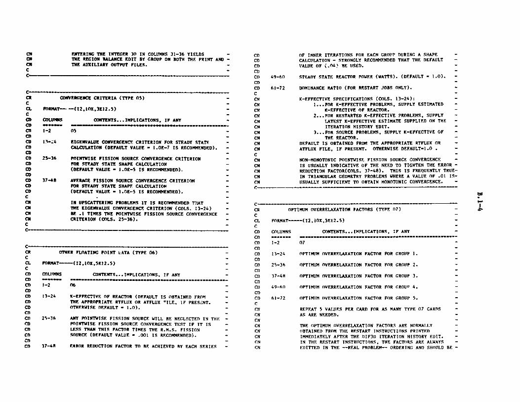
F.NTERING THE INTEGER 30 IN COLUMNS 31-36 YIELDS -THE REGION BALANCE EDIT BY GROUP ON BOTH THE PRINT AND -THE AUXILIARY OUTPUT FILES. -
CONVERGENCE CRITERIA (TYPE 05)
FORMAT--- -(12,1OX,3E12.5)
COLUPS CONTENTS...IMPLICAlm=m==i M M=ininmintmininininmmm
1-2 05
TIONS, IF ANY=============================-
CNCmCmC
13-24 EIGENVALUE CONVERGENCE CRITERION FOR STEADY STATECALCULATION (DEFAULT VALUE " 1.0E-7 IS RECOMMENDED).
25-36 POINHWISE FISSION SOURCE CONVERGENCE CRITERIONFOR STEADY STATE SHAPE CALCULATION(DEFAULT VALUE " 1.0E-5 IS RECOMMENDED).
37-48 AVERAGE FISSION SOURCE CONVERGENCE CRITERIONFOR STEADY STATE SHAPE CALCULATION(DEFAULT VALUE " 1.0E-5 IS RECOMMENDED).
IN UPSCATTERING PROBLEMS IT IS RECOMMENDED Th!ATTHE EICENVALUE CONVERGENCE CRITERION (COLS, 13-24)BE .1 TIMES THE POINTWISE FISSION SOURCE CONVERGENCECRITERION (COLS. 25-36).
OTHER FLOATING POINT LATA (TYPE 06) -
FORMAT----(I2,10X,5E12.5)
COLUMNS CONTENTS... IMPLICATIONS, IF ANY -
1-2 06-
13-24 K-EFFECTIVE OF REACTOR (DEFAULT IS OBTAINED FROM -THE APPROPRIATE RTFLUX OR ATFLUX VILE, IF PRESENT. -OTHERWISE DEFAULT - 1.0). -
25-36 ANY POINTISE FISSION SOURCE WILL RE NEGLE.CTED IN THE -POINTHISE FISSION SOURCE CONVERGENCE TEST IF IT IS -LESS THAN THIS FACTOR TIMES THE R.M.S. FISSION -SOURCE (DEFAULT VALUE - .001 IS RECOMMENDED). -
37-48 ERROR REDUCTION FACTOR TO RE ACHIEVED RY EACH SERIES -
CRCCLCCDCDCDCDCDCDCDCDCDCDCDCDCDCDCCmCN
CNC
49-60
61-72
CDCDCDCD)CDCDCDCCNCNCNCNCNCNCNCNCNCNCCNCNCNCNCN
OPTIMUM OVERRELAXATION FACTORS (TYPE 07) -
FORMAT-----(12, I OX , 5E 12.5)
COLUMNS CONTENTS... IMPLICATIONS, IF ANY
1-2 07
13-24 OPTIMISM OVERRELAXATION FACTOR FOR GROUP 1.
25-36 OPTIMUM OVERRELAXATION FACTOR FOR GROUP 2. -
37-4R OPTIMUM OVERRELAXATION FACTOR FOR GROUP 3.
49-60 OPTIMUM OVERRELAXATION FACTOR FOR GROUP 4.
61-72 OPTIMUM OVERRELAXATION FACTOR FOR GROUP 5.
REPEAT 5 VALUES PER CARD FOR AS MANY TYPE 07 CARDSAS ARE NEEDED.
THE OPTIMUM OVERRELAXATION FACTORS ARE NORMALLYOBTAINED) FROM THE RESTART INSTRUCTIONS PRINTEDIMMEDIATELY AFTER THE DIF3D ITERATION HISTORY EDIT.IN THE RESTART INSTRUCTIONS, THE FACTORS ARE ALWAYSE.ITTED IN THE -- REAL PROBLEM-- ORDERING AND SHOULD BE -
OF INNER ITERATIONS FOR EACH GRO11P DURING A SHAPE -CALCULATION - STRONGLY RECOMMENDED THAT THE DEFAULT -
VALUE OF (.n46 RE USED.
STEADY STATE REACTOR POWER (WATTS). (DEFAULT s 1.0). -
DOMINANCE RATIO (FOR RESTART JOBS ONLY).
K-EFFECTIVE SPECIFICATIONS (COLS. 13-24):1...FOR K-EFFECTIVE PROBLEMS, SUPPLY ESTIMATED -
K-EFFECTIVE OF REACTOR.2...FOR RESTARTED K-EFFECTIVE PROBLEMS, SUPPLY -
LATEST K-EFFECTIVE ESTIMATE SUPPLIED ON THE -ITERATION HISTORY EDIT.
3...FOR SOURCE PROBLEMS, SUPPLY K-EFFECTIVE OF -THE REACTOR.
DEFAULT IS OBTAINED FROM THE APPROPRIATE RTFLUX OR -ATFLUX FILE, IF PRESENT. OTHERWISE DEFAULT=1.0 . -
NON-MONOTONIC POINTWISE FISSION SOURCE CONVERGENCE -IS USUALLY INDICATIVE OF THE NEED TO TIGHTEN THE ERROR -
REDUCTION FACTOR(COLS. 37-48). THIS IS FREQUENTLY TRUE-
IN TRIANGULAR GEOMETRY PROBLEMS WHERE A VALUE OF .01 IS-USUALLY SUFFICIENT TO OBTAIN MONOTONIC CONVERGENCE. -
C
C
CRCCLCCDCDCDCTCDCD
CDCI)CDCDCI)CD
CDCCNCNCN
CN
CNCNCN
CN
C -
CRCCLCCDCDCDCDCDCDCDCDCD
CD
CDCD
to"-
CM M M M M M M M e

ENTERED ON THE TYPE 07 CARD -- EXACTLY-- AS EDITTED -IN THE RESTART INSTRUCTIONS.
THE PERMISSIBLE FACTOR RANGE IS BOUNDED BY 1.0 ANY) 2.0 -INCLUSIVE. A ZERO OR BLANK FACTOR ENTRY DEFAULTS -TO 1.0. FACTORS ARE COMPUTED FOR THOSE GROUPS HAVING -A FACTOR OF 1.0; FACTORS GREATER THAN 1.0 ARE NOTRECOMPUTED. -
TYPE 07 CARS ARE PRIMARILY INTENDED F:)R RESTART JOBS -ONLY (STRONGLY RECOMMENDED).
NEAR CRITICAL SOURCE PROBLEM ASYMPTOTIC EXTRAPOLATION
PARAMETERS (TYPE 08)
"** WARNING...SELECT T4IS OPTION ONLY IF THE "**
**** ASYMPTOTIC EXTRAPOLATION IS REQUIRED FOR "**
!** THIS PROBLEM. **
FORMAT----(2,X,I6,E12.5)
COLUMNS CONTENTS... IMPLICATIONS, IF ANY
1-2'i*n'in*r*n**'inr* n mr' nr-nrnr*" n-rn- a --- t- -its ----n ----
08
/-12 NUMBER OF OUTER (POWER) ITERATIONS PERFORMED PRIOR TOASYMPTOTIC EXTRAPOLATION OF NEAR CRITICAL SOURCEPROBLEM (DEFAULT-5).
13-24 EIGENVALUE OF THE HOMOGENEOUS PROBLEM CORRESPONDINGTO THE NEAR CRITICAL SOURCE PROBLEM. THIS EICENVALUEMUST BE LESS THAN ONE.
25-30 INITIAL FLUX GUESS SENTINEL.O...FLAT FLUX GUESS-1.0 (DEFAULT)1... FLAT FLUX GUESS-O.0
THE TYPE 08 CARD IS REQUIRED TO ACTIVATE AN ALTERNATESPECIAL ACCELERATION SCHEME FOR NEAR CRITICALSOURCE PROBLEMS.
IF COLS. 13-24 ARE ZERO OR BLANK, THE HOMOGENEOUSPROBLEM EIGENVALUE WILL BE ESTIMATED. IN THIS CASE, ITIS RECOMMENDED TO INCREASE THE NUMBER OF ITERATIONS INCOLS. 7-12 TO AT LEAST 10.
C M
C
CRCCLCCDC!)CDCDCDCD
CDCDCDCDCCNCNCNLRi
SN TRANSPORT OPTIONS (TYPE 09) -
FORMAT-----(I2,4X,216,6X,E12.4)
COLUMNS CONTENTS...IMPLICATIONS, IF ANY-==--== ==--------s- ---- s--"s"" -="***"* -s-"""""" -"""" -""" -
1-2 09
7-12 SN ORDER. -
13-18 MAXIMUM ALLOWED NUMBER OF LINE SWEEPS PER LINE PER -INNER ITERATION (DEFAULT-10). -
25-36 LINE SWEEP CONVERGENCE CRITERION (DEFAULT-I.0E-4). -
TO INVOKE THE DIF3D TRANSPORT OPTION, THE TYPE 09 CARD -MUST BE PRESENT WITH A NONZERO SN ORDER. FOR THE TIME -BEING, USERS MUST ALSO CONTINUE TO 'PRELIB' TO -
DATASET 'C116.B99983.MODLIB' TO INVOKE THIS OPTION. -
C- - mo- ---- - ---- ww
C- - w - - - - -w w w
CR
CCLCCDCD
CDCDCT)CDCDCDCDCDCDCDCI)CD
CDCDCisC!)CDCDCD
CDCD
CN
PARAMETERS FOR NODAL HEXAGONAL GEOMETRY OPTION (TYE 1 )) -
FORMAT-----(12,4X,516) -
COLUMNS CONTENTS... IMPLICATIONS, IF ANY -
1-2 10
7-12 ORDER OF NODAL APPROXIMATION IN HEX-PLANE. -2...NH2 APPROXIMATION. -3...NH3 APPROXIMATION. -4..NH4 APPROXIMATION (DEFAULT). -
13-18 ORDER OF NODAL APPROXIMATION IN Z-DIRECTION. -2...QUADRATIC APPROXIMATION. -
3...CUBIC APPROXIMATION (DEFAULT). -
19-24 COARSE-MESH REBALANCE ACCELERATION CONTROL. --1...NO COARSE-MESH REBALANCE ACCELERATION. -
.CE.O...NUMBER OF COARSE-MESH REBALANCE ITERATIONS PER -OUTER ITERATION (DEFAULT-2).
25-30 ASYMPTOTIC SOURCE EXTRAPOLATION OF OUTER ITERATIONS. -0...APPLY ASYMPTOTIC SOURCE EXTRAPOLATION TO OUTER -
ITERATIONS (DEFAULT).1...NO ASYMPTOTIC SOURCE EXTRAPOLATION. -
31-36 NUMBER OF AXIAL PARTIAL CURRENT SWEEPS PER GROUP -PER OUTER ITERATION (DEFAULT=2).
THE TYPE 10 CAR!) IS PERTINENT ONLY WHEN THE NODA. -
CNCscNCNCN
CNCNCmCsC
C
I.
c
CRCRCCCCCCCC-CLCCDCDCDCDCDCDCDCDCD
CDCDCDCDCDCCN
CNCM
CNCN
C
to
".,

HEXAGONAL GEOMETRY OPTION (A.NIP3 TYPE 03 CARDGEOMETRY-TYPE SENTINEL VALUES BETWEEN 110 AND 128)IS SPECIFIED.
IT IS RECOMMENDED THAT THE DEFAULT VALUES FOR THEORDER OF THE NODAL APPROXIMATION IN THE HEX-PLANE(COLS. 7-12) AND FOR THE ORDER OF THE NODAL APPROXI-MATION IN THE Z-DIRECTION (COLS. 13-18) BE SPECIFIED.
AXIAL COARSE-MESH REBALANCE BOUNDARIES FOR NCDALHEXAGONAL GEOMETRY OPTION (TYPE 11)
PORMAT-----(12,1OX,3(16,E12.5))
COLUMNS CONTENTS... IMPLICATIONS, IF ANY
11 -
NUMBER OF AXIAL COARSE-MESH REBALANCE INTERVALS. -
UPPER Z-COORDINATE.
NUMBER OF AXIAL COARSE-MESH REBALANCE INTERVALS. -
UPPER 7.-COORDINATE.
NUMBER OF AXIAL COARSE-MESH REBALANCE INTERVALS. -
UPPER 7.-COORDINATE.,-
THE TYPE 11 CARD IS PERTINENT ONLY WHEN THE THREE- -DIMENSIONAL NODAL HEXAGONAL GEOMETRY OPTION (A.NIP3 -TYPE 03 CARD GEOMETRY-TYPE SENTINEL VALUES BETWEEN -120 AND 128) IS SPECIFIED. -
IF NO TYPE 11 CARDS ARE PRESENT, THE AXIAL COARSE-MESH -REBALANCE INTERVALS ARE DEFINED BY THE Z-COORDINATE -VALUES SPECIFIED ON A.NIP3 CARD 09. -
BOUNDARIES ARE SPECIFIED VIA NUMBER PAIRS. -EACH NUMBER PAIR IS OF THE FORM (N(I), 7.(I)). THERE -ARE N(I) AXIAL COARSE-MESH REBALANCE INTERVALS BETWEEN -7.(I-1) AND Z(I), WHERE 7.(O) IS THE LOWER REACTOR -BOUNDARY IN THE Z-DIRECTION. NUMBER PAIRS MUST BE -GIVEN IN ORDER OF INCREASING MESH COORDINATES. ALL -AXIAL COARSE-MESH REBALANCE BOUNDARIES MUST COINCIDE -WITH THE MESH LINES WHICH BOUND MESH INTERVALS. -
CNCMCMCmCMCMCmCmC
CoCDCDCDCDCD
CDoCDCDCDCDCDCDCDCD
Co
CMCMCMCMCMCMCNCMCMCMCMCMCMCMCMCM
C
CEOF
PROBLEM OPTIONS (TYPE 02)
FORMAT----(12,4X,816)
COLUMNS
1-2
CONTENTS... IMPLICATIONS, IF ANY -
02 -
7-12 SIZE OF MAIN CORE CONTAINER ARRAY IN REAL*R WORDS(SINGLE WORDS ON CDC SYSTEMS). (DEFAULT-20000).
13-18 PRINT FILE MASTER CONTROL FlAG.n...PRINT GENERA!. RUN INFORMATION AND REQUESTED EDITS
(DEFAULT).1...SUIPPRESS ALL PRINTING EXCEPT DIAGNOSTICS.
B.2 A.HMG4C
C PREPARED 9/26/79 AT ANL-C -CF A.HMG4C -CE INPUT FOR CCCC TO ARC SYSTEM CROSS SECTION HOMOGENIZATION -CCN THIS IS A USER-SUPPLIED BCD DATA SET. -CN THE LIST FOR EACH RECORD IS GIVEN IN TERMS -CN OF THE BCD FORMAT OF THAT DATA CARD. -CN COLUMNS 1-2 NORMALLY CONTAIN THE CARD TYPE -CN NUMBER. -CN A BLANK FIELD GIVES THE DEFAULT OPTION -CN INDICATED. -CN ALL INPUT CARDS ARE OPTIONAL. -C
CCR PROBLEM TITLE (TYPE 01) -CCL FOR1'AT--(I2,4X,11A6)C -CD COLUMNS CONTENTS...IMPLICATIONS, IF ANY -CD ------ ------------------------------------------------------
CD 1-2 01 -Cn -CD 7-72 ANY ALPHANUMERIC CHARACTERS. -C -CN 'P TO SIX TYPE 01 CARDS MAY BE USED. -C -C-
C-
C
C-CRCRCCL
1-2
13-1B
19-30
31-36
37-48
49-54
55-66
CRCC1.CCDCDCnCDCDCnCDCI)CDCDCDCD
wto

CDCDCDCDCDCDCDCDCDCDCDCDCDCDCDCDCDCDCDCDCDCDCDCDCDCDCDCDCDCDCDCDCDCDCDCDCDCDCDCDCDCDCDCDCDCDCDCDCD
CDCDCDCDCD
- CD
- CD
- CD
- CD
- CD
- CD
- CD
- CD
- CD
- CD
- C
NOTE THAT ERROR DIAGNOSTICS ARE NOT WRITTEN ON THEAUXILIARY OUTPUT FILE.
49-54 EDIT FLAG FOR A SUPPLIED COMPXS FILE.0....NO EDIT (DEFAULT).1...PRINT COMPLETE EDIT OF SUPPLIED COMPXS FILE.
2...WRITE COMPLETE EDIT OF SUPPLIED COMPXS FILE ONTHE AUXILIARY OUTPUT FILE.
3... EDIT OF SUPPLIED COMPXS WRITTEN ON BOTH PRINT AND
AUXILIARY OUTPUT FILES.
19-24 COMPXS EDIT FLAG.0...NO EDIT (DEFAULT).1...PRINT COMPLETE EDIT OF THE CREATED COMPXS FILE.
2...WRITE COMPLETE EDIT OF THE CREATED COMPXS FILEON THE AUXILIARY OUTPUT FILE.
3...COMPXS EDIT WRITTEN ON BOTH PRINT AND AUXILIARYOUTPUT FILES.
25-30 ISOTXS EDIT FLAG.0...NO EDIT (DEFAULT).1...PRINT RUNNING EDIT OF ISOTXS (I.E. NOT EVERY
ISOTOPE ON THE FILE IS PRINTED, ONLY THOSEACTUALLY REFERENCED).
2...WRITE RUNNING EDIT OF ISOTXS ON THE AUXILIARYOUTPUT FILE.
3...RUNNING EDIT OF ISOTXS WRITTEN ON BOTH PRINTAND AUXILIARY OUTPUT FILES.
31-36 POINTR DEBUGGING EDIT FLAG.O...NO DEBUGGING PRINTOUT (DEFAULT).1...DUMP PRINTOUTS ONLY.2...TRACE PRINTOUTS ONLY.3...BOTH TRACE AND DUMP PRINTOUT.
NOTE THAT HMG4C CONTAINS NO DUMPS, I.E. I IS NOT
A RELEVANT VALUE FOR THIS FLAG.
CCRCCLCCDCDCDCDCDCCNCNCNCNCNCNCNCNCNCNC
37-42 PROMPT FISSION SPECTRUM OPTION FLAG. -0... IGNORE ISOTOPE FISSION VECTORS, IF PRESENT IN -
ISOTXS, AND USE THE SET FISSION VECTOR FOR ALL -COMPOSITIONS (DEFAULT). IF A SET FISSION SPECTRUM -IS NOT PRESENT IN ISOTXS, THE COMPOSITION FISSION -SPECTRA WILL BE COMPUTED BY THE TOTAL FISSION -SOURCE WEIGHTING METHOD USING ISOTOPE FISSION -VECTORS. -
1...USE ISOTOPE FISSION VECTORS, IF PRESENT IN ISOTXS, -TO COMPUTE COMPOSITION FISSION VECTORS WITH TOTAL -FISSION SOURCE WEIGHTING, I.E., UNDER ASSUMPTION -THAT FLUX IS GROUP INDEPENDENT. THIS IS THE -PREFERRED WEIGHTING METHOD. IF AN ISOTOPE FISSION -VECTOR IS NOT PRESENT, THE SET FISSION VECTOR WILL -BE USED IN ITS PLACE. -
2...USE ISOTOPE FISSION VECTORS, IF PRESENT IN ISOTXS, -TO COMPUTE COMPOSITION FISSION VECTORS WITH -N11*SIGMA(FISSION) WEIGHTING. THIS METHOD OF -COMPUTING A FISSION SPECTRUM IS NOT RECOMMENDED. -IF AN ISOTOPE FISSION VECTOR IS NOT PRESENT, THE -SET FISSION VECTOR WILL BE USED IN ITS PLACE. -
63-48 AUXILIARY OUTPUT FILE MASTER CONTROL FLAG. -0...SUPPRESS ALL OUTPUT TO AUXILIARY FILE (DEFAULT). -1...WRITE GENERAl. RUN INFORMATION AND REQUESTED -
EDITS ON AUXILIARY OUTPUT FILE. -
SCATTERING CROSS SECTION TRUNCATION OPTION (TYPE 03) -
FORMAT- (12,4XE12.5)
COLUMNS CONTENTS... IMPLICATIONS, IF ANY -
1-2 03
7-18 SCATTERING MATRIX TRUNCATION FRACTION (DEFAUILT-1.0) -
THE SCATTERING CROSS SECTION BANDWIDTH OF A -
COMPOSITION IN FILE COMPXS IS TRUNCATED AT -
THE POINT WHERE THE INPUT FRACTIOt (COL 7-18) -OF THE TOTAL SCATTERING CROSS SECTION HAS -BEEN ACCUMULATED. A VALUE OF .999 IS -GENERALLY SUFFICIENT TO RETAIN THE RIGOR -OF A CALCULATION WHILE SIGNIFICANTLY REDUCING -THE SCATTERING BANDWIDTH AND HENCE, THE I/O -
TIMES ASSOCIATED WITH THE SCATTERING SOURCE -DETERMINATION IN A NEUTRONICS CALCULATION. -
CEOF
R.3 A.ISO (SEE ISOTXS FILE DESCRIPTION)
c--- --- ---- -.----- - - - - M
w
------------
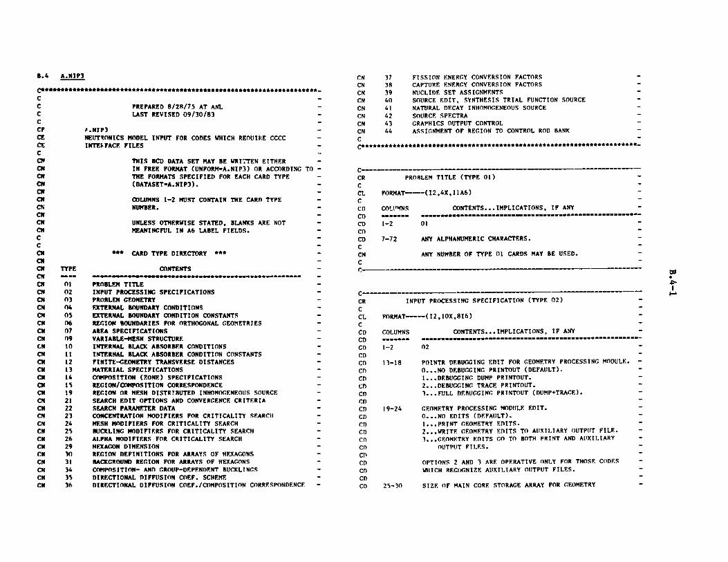
PREPARED 8/28/75 AT ANLLAST REVISED 09/30/83
A.NIP3NEUTRONICS MODEL INPUT FOR CODES WHICH REOUIPE CCCCINTEI FACE FILES
THIS BCD DATA SET MAY BE WRITTEN EITHERIN FREE FORMAT (UNFORM-A.NIP3) OR ACCORDINGTHE FORMATS SPECIFIED FOR EACH CARD TYPE(DATASET-A.NIP3).
C**CCCCCFCECECCNCMCmCRCMCNCMCMCNCRNCCCNCRCNCRCNCNCRCNCNCNCNCmCNCNCNCNCRCMCNCRCNCRCNCRCmCmCNCNCNCNCN
CNCNCN
- CN- CN
- CN
- CN- CN
3738394041424344
FISSION ENERGY CONVERSION FACTORSCAPTURE ENERGY CONVERSION FACTORSNUCLIDE SET ASS IGNMENTSSOURCE EDIT, SYNTHESIS TRIAL FUNCTION SOURCENATURAL DECAY INHOMOGENEOUS SOURCESOURCE SPECTRAGRAPHICS OUTPUT CONTROLASSIGNMENT OF REGION TO CONTROL ROD BANK
- C
- C********************************************************** _
TO -
CRCCLCCDCDCDCDCDCCNC
** CARD TYPE DIRECTORY ***
CONTENTS
PROBLEM TITLEINPUT PROCESSING SPECIFICATIONSPROBLEM GEOMETRYEXTERNAL BOUNDARY CONDITIONSEXTERNAL BOUNDARY CONDITION CONSTANTSREGION BOUNDARIES FOR ORTHOGONAL GEOMETRIESAREA SPECIFICATIONSVARIABLE-MESH STRUCTUREINTERNAL BLACK ABSORBER CONDITIONSINTERNAL BLACK ABSORBER CONDITION CONSTANTSFINITE-GEOMETRY TRANSVERSE DISTANCESMATERIAL SPECIFICATIONSCOMPOSITION (ZONE) SPECIFICATIONSREGION/COMPOSITION CORRESPONDENCEREGION OR MESH DISTRIBUTED INHOMOGENEOUS SOURCESEARCH EDIT OPTIONS AND CONVERGENCE CRITERIASEARCH PARAMETER DATACONCENTRATION MODIFIERS FOR CRITICALITY SEARCHMESH MODIFIERS FOR CRITICALITY SEARCHBUCKLING MODIFIERS FOR CRITICALITY SEARCHALPHA MODIFIERS FOR CRITICALITY SEARCHHEXAGON DIMENSIONREGION DEFINITIONS FOR ARRAYS OF HEXAGONSBACKGROUND REGION FOR ARRAYS OF HEXAGONSCOMPOSITION- AND GROUP-DEPENDENT BUCKLINGSDIRECTIONAL DIFFUSION COEF. SCHEMEDIRECTIONAL DIFFUSION COEF./COMPOSITION CORRESPONDENCE
CRCCLCCDCDCDCDCDCDCDCDCDCDCDCDCDCDCDCDChCDCDCDCD
PROBLEM TITLE (TYPE 01)
FORMAT---(12,4X,11A6)
COL"'MNS==mum==1-2
7-72
CONTENTS... IMPLICATIONS, IF ANY
01
ANY ALPHANUMERIC CHARACTERS.
ANY NUMBER OF TYPE 01 CARDS MAY BE USED.
INPUT PROCESSING SPECIFICATION (TYPE 02)
FORMAT---(12 ,JOX,816)
COLUMNS
1-2
CONTENTS... IMPLICATIONS, IF ANY
02
13-18 POINTR DEBUGGING EDIT FOR GEOMETRY PROCESSING MODULE.
0...NO DEBUGGING PRINTOUT (DEFAULT).
1...DEBUGGING DUMP PRINTOUT.
2... DEBUGGING TRACE PRINTOUT.3...FULL DEBUGGING PRINTOUT (DUMP+TRACE).
19-24 GEOMETRY PROCESSING MODULE EDIT.0...NO EDITS (DEFAULT).1...PRINT GEOMETRY EDITS.2...WRITE GEOMETRY EDITS TO AUXILIARY OUTPUT FILE.3...GEOMETRY EDITS GO TO BOTH PRINT AND AUXILIARY
OUTPUT FILES.
OPTIONS 2 AND 3 ARE OPERATIVE ONLY FOR THOSE CODESW1ICH RECOGNIZE AUXILIARY OUTPUT FILES.
25-30 SIZE OF MAIN CORE STORAGE ARRAY FOR GEOMETRY
B.4 A.NIP3
COLUMNS 1-2 MUST CONTAIN THE CARD TYPENUMBER.
UNLESS OTHERWISE STATED, BLANKS ARE NOTMEANINGFUL IN A6 LABEL FIELDS.
TYPE.gym.010203040506070910111213141519212223242526293031343536
to"-
R!!"*******!!!!**!****!*!*******f***l***!!*********A#
r M M M G M M M ~ i M M N -W -
r. - -M M M N M i M

CDCDCDCDCDCDCDCDCDCDCDCDCDCDCDCDCDCDCDCDCDCDCDCDCDCDCDCDCDCDCDCDCDCDCDCDCDCDCDCnCDCDCDCMCMCNCMCMCMC
PROCESSING MODULE (GNIP4C) IN REAL*8 WORDS -(DEFAULT-10000).-
31-16 SIZE OF BULK CORE STORAGE ARRAY FOR GEOMETRY -PROCESSING MODULE (GNIP4C) IN REAL*8 WORDS -(DEFAIILT-O).
37-42 SIZE OF MAIN CORE STORAGE ARRAY FOR CROSS SECTION -PROCESSING MODULES IN REAL*8 WORDS (DEFAULT - 20000). -
43-48 SIZE OF BULK CORE STORAGE ARRAY FOR CROSS SECTION -PROCESSINC MODULES IN REAL*8 WORDS (DEFAULT-O). -
49-54 POINTR DEUGCING EDIT FOR CROSS SECTION PROCESSING -MDULES. -0...NO DEBUGGING PRINTOUT (DEFAULT). -1...DEBU(GING DUMP PRINTOUT. -2...DEBUGCING TRACE PRINTOUT. -'...FULL DEBUCCING PRINTOUT (DUMP+TRACE). -
55-60 CROSS SECTION PROCESSING EDIT. -0... NO EDITS (DEFAULT). -1...PRINT CROSS SECTION EDITS. -
2...WRITE CROSS SECTION EDITS TO AUXILIARY OUTPUT FILE.-...CROSS SECTION EDITS GO TO ROTH PRINT AND AUXILIARY -
OUTPUT FILES. -
61-66 REGION/MESH INTERVAL PRINTER-PLOTTER MAP EDIT DURING -
GEOMETRY PROCESSING.0...NO MAP (DEFAULT). -I...PRINT REGION MAP.2...WRITE REGION MAP TO AUXILIARY OUTPUT FILE. -3...WRITE REGION MAP TO BOTH PRINT AND AUXILIARY OUTPUIT-
FILES.-
67-72 ZONE(COMPOSITION)/MESH INTERVAL PRINTER-PLOTTER :-AP -
EDIT DURING GEOMETRY PROCESSING.0.. .NO RIAP (DEFAULT).-1...PRINT ZONE MAP. -
2...WRITE ZONE MAP TO AUXILIARY OUTPUT FILE.3...WRITE ZONE MAP TO BOTH PRINT AND AUXILIARY OUTPIUT -
FILES. -
EDIT OPTIONS 2 AND 3 ARE OPERATIVE ONLY FOR THOSE -CODES WHICH RECOGNIZE AUXILIARY OUTPUT FILES. -
THE PRINTER-PLOTTER MAP OPTIONS (CO.S. 61-72) ARE -
ENTIRELY SEPARATE FROM THE GRAPHICS MAP OPTIONS -IN COLS. 7-48 OF THE TYPE 43 CARD. -
CRCCLCCDCDCDCDCDCDCDCDCDCDCDCDCDCDCDCDCDCDCDCDCDCDCDCDCDCDCDCDCDCDCDCl)CDCDCDCDCDCDCDCDCDCDCDCDCr)cc
PROBLEM GEOMETRY SPECTFICATION (TYPE 03)
FORMAT-----(12 ,10X,16) -
COLUMNS CONTENTS... IMPLICATIONS, IF ANY.
1-2 03
13-18 GEOMETRY TYPE.10...SLAB20...CYLINDER -30... SPHERE40...X-Y44...X-Y-Z50. .. R-Z -60... R-THETA62... R-THETA-Z64...THETA-R66...THETA-R-Z7-70...TRIANCULAR, RHOMBIC BOUNDARY, CORE CENTER AT -
60 DEGREE ANGLE (SIXTH CORE SYMMETRY). -72... TRIANGULAR, RECTANGULAR BOUNDARY, HALF CORE -
SYMMETRY.74...TRIANGULAR, RHOMBIC BOUNDARY, CORE CENTER AT -
120 DEGREE ANGLE (THIRD CORE SYMMETRY). -76...TRIANGULAR, 60 DECREE TRIANGULAR BOUNDARY, -
SIXTH CORE SYMMETRY. -78...TRIANGULAR, RECTANGULAR BOUNDARY, QUARTER -
CORE SYMMETRY. -80...TRIANGULAR, RECTANGULAR BOUNDARf, FULL CORE. -90...TRIANGULAR-Z, RHOMBIC BOUNDARY :N PLANE, CORE -
CENTER LINE AT 60 DEGREE ANGLE. -92...TRIANGIJLAR-Z, RECTANGULAR BOUNDARY IN PLANE, -
HALF CORE SYMMETRY IN PLANE. -94...TRIANGULAR-Z, RHOMBIC BOUNDARY IN PLANE, CORE -
CENTER LINE AT 120 DEGREE ANGLE. -96...TRIANGULAR-Z, 60 DEGREE TRIANGULAR BOUNDARY -
IN PLANE.-98...TRIANCIILAR-Z, RECTANGULAR BOUNDARY IN PLANE, -
QUARTER CORE SYMMETRY IN PLANE. -100...TRIANGULAR-Z, RECTANGULAR BOUNDARY IN PLANE, -
FULL CORE IN PLANE. -110...HEXAGONAL, FULL CORE. -114...HEXAGONAL, SIXTH CORE SYMMETRY. -116...HEXAGONAL, THIRD :ORE SYMMETRY. -120...HEXAGONAL-Z, FULL CORE IN PI.ANE. -124...HEXAGONAL-Z, SIXTH CORE SYMMETRY IN PLANE. -126...HEXAGONAL-Z, THIRD CORE SYMMETRY IN PLANE. -
w
to
c-
C - - - - -w~ w
MMw M M l +

CR
CLCCDCDCDCDCDCDCDCDCDCDCDCDCDCDCDCDCDCDCDCDCDCDCDCDCDCDCDCDCDCDCDCMCNCNCNCNCNCNCNCNCNCNCNCNCNCNCNCNCN
CNCN
CNCNCNCNCNCNCNCNCN
CNCNC
EXTERNAL BOUNDARY CONDITIONS (TYPE 04) -
FORMAT-----(I2,1OX,616) -
COLUMNS CONTENTS...IMPLICATIONS, IF ANY -
1-2 04 -
3-18 BOUNDARY CONDITION AT LOWER "X" BOUNDARY OF REACTOR. -
19-24 BOUNDARY CONDITION AT UPPER "X" BOUNDARY OF REACTOR. -
25-30 BOUNDARY CONDITION AT LOWER "Y BOUNDARY OF REACTOR. -
31-36 BOUNDARY CONDITION AT UPPER "Y" BOUNDARY OF REACTOR. -
37-42 BOUNDARY CONDITION AT LOWER Z BOUNDARY OF REACTOR. -
43-48 BOUNDARY CONDITION AT UPPER Z BOUNDARY OF REACTOR. -
2. *.PH!-O.-
3.. .PHI PRIME.4...D * PhIPRIMF+A *PHI "O.-6... REPEATING (PERIODIC, WITH OPPOSITE FACE.-7... REPEATING (PERIODIC) WITH NEXT U Y )JACENT BOUNDARY -
(SEE DISCUSSION BELOW).-8...-INVERTED REPEATING ALONG THIS FACE-
(180 DECREE ROTATION).-9...INCOMINC ANGULAR FLUX ZERO (TRANSPORT ONLY). -
10. .REFLECTIVE (TRANSPORT ONLY).-11..PERIODIC (TRANSPORT ONLY).-12..WHITE (TRANSPORT ONLY).-
PHI PRIME IS THE DERIVATIVE OF THE FLUX IN THE -DIRECTION OF THE REACTOR OUTWARD NORMAL. D IS THE -DIFFUSION COEFFICIENT [N THE MESH INTERVAL-IMMEDIATELY INSIDE THE REACTOR BOUNDARY. IF COLS. -43-48 ARE 4 AND NO TYPE 05 CARD IS SUPPLIED TO SPECIFY -THE CONSTANT A, THE VALE 0.46920 WILL BE USED BY -DEFAULT. E-
CONDITIONS 2-8 APPLY TO DIFFUSION THEORY PROBLEMS, -AND 9-12 APPLY TO TRANSPORT THEORY PROBLEMS.Y-
X.REPRESENTS THE FIRST DIMENSION COORDINATE (X IN -X-Y.EOETRY, R TNR-Z, ETC.). "Y REPRESENTS THE -
SECOND DIMENSION COORDINATE (Y IN X-Y GEOMETRY, 7.IN -R-, ETC.). WHEN THE MODEL IS THREE-DIMENSIONAL, THE -
THIRD DIMENSION IS ALWAYS Z.-
REPEATING CONDITIONS (6,7,8) ARE ONLY APPLICABLE TC -
THE FIRST TWO DIMENSIONS.
NOTE FOR REPEATING CONDITION 7. LET XL DENOTE THE
LOWER "X" BOUNDARY, XU DENOTE THE UPPER "X" BOUNDARY,YL DENOTE THE LOWER "Y" BOUNDARY AND YU DENOTE THE
UPPER Y BOUNDARY. FOR REPEATING BOUNDARY CONDITIONS
(CONDITION 7), THE SEQUENCE OF BOUNDARIES IMPLIED BY
THE TERM "NEXT ADJACENT BOUNDARY" IS XL, YL, XU, YU.
OF THE TWO BOUNDARIES INVOLVED, THE ONE APPEARING
FIRST IN THE SEQUENCE IS ASSIGNED THE BOUNDARYCONDITION (7), THE SECOND IS IGNORED. FOR EXAMPLE,
IF XL AND YL ARE THE PERIODIC BOUNDARIES, COLS. 13-18
MUST CONTAIN A 7, COLS. 25-30 WILL BE IGNORED.
EXTERNAL BOUNDARY CONDITION CONSTANTS (TYPE 05) -
FORMAT----(2,8X,A2,E12.5,12X,2I6)
COLUMNS CONTENTS...IMPLICATIONS, IF ANY--
1-2 05
11-12 BOUNDARY DESIGNATOR.-
XL..."X" LOWER.XU1..."X" IPPER.-YL..."Y" LOWER.YU. . . "Y" UPPER.ZL...7. LOWER.7.11...7 IPPER.
13-24 VALUE OF CONSTANT A REFERRED TO ON CARD TYPE 04. -
37-42 HIGHER-ENERGY GROUP NUMBER FOR WHICH CONSTANTS APPLY. -
43-48 LOWER-ENERGY GROUP NUMBER FOR WHICH CONSTANTS APPLY. -
AS MANY TYPE 05 CARDS AS NECESSARY MAY BE USED TO -
SPECIFY THE EXTERNAl. BOUNDARY CONDITIONS.
IF NO "HIGHER-ENERGY GROUP NUMBER" IS SUPPLIED (COLS. -
37-42 ARE BLANK), THE CONSTANTS GIVEN APPLY TO ALlT -
ENERGY GROUPS. IF NO "LOWER-ENERGY GROUP NUMBER" IS -:IPPLIFD (COLS. 43-48 ARE BLANK), THE CONSTANTS GIVEN -
APPI.Y TO THE "HIGHER-ENERGY GROUP" ONLY. IF NO GROUP -
NUMBERS ARE SIIPPLIED (COLS. 37-48 ARE BLANK), THE -
CONSTANTS GIVEN APPLY TO ALL ENERGY GROUPS. -
DATA ON THIS CAR!) MAY BE OVERLAYED. THAT IS, BOUNDARY -
CONSTANTS DEFINED) ON LATER TYPE 5 CARDS SIIPERCEDF DATA -
FOR ENERGY RANGES PREVIOUSLY SPECIFIED.
CRCCLCCDCDCDCD
CDCDCDCDCDCDCDCD
CDCl)CDCDCDCCNCNCNCNCNCN
CNCNCNCNCNCN
CNCN
w
C
C----------Y-
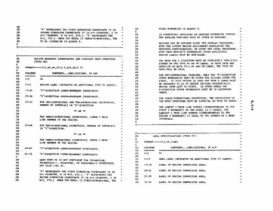
"X" REPRESENTS THE FIRST DIMENSION COORDINATE (X INSECOND DIMENSION COORDINATE (Y IN X-Y GEOMETRY, Z INX-Y GEOMETRY, R IN R-Z, ETC.). "Y" REPRESENTS THER-Z, ETC.). WHEN THE MODEL IS THREE-DIMENSIONAL, THET!i:RL DIMENSION IS ALWAYS Z.
C - - _
REGION BOUNDARY COORDINATES AND CONSTANT MESH STRUCTURE -(TYPE 06) -
FORMAT-----(I2,4X,A6,2E12.5,26,2E12 5) -
COLUMNS CONTENTS... IMPLICATIONS, IF ANY --------- --------------------------------------------------------
1-2 06 -
7-12 REGION LABEL (REPEATED ON ADDITIONAL TYPE 06 CARDS). -
13-24 "X"-DIRECTION LOWER-BOUNDARY COORDINATE. -
25-36 "X"-DIRECTION UPPER-BOUNDARY COORDINATE. -
37-42 FOR ONE-DIMENSIONAL AND TWO-DIMENSIONAL. GEOMETRIES, -NUMBER OF INTERVALS IN "X"-DIRECTION. -
** OR ** -
FOR THREE-DIMENSIONAL GEOMETRIES, LOWER Z MESH -LINE NUMBER OF THE REGION. -
43-48 FOR TWO-DIMENSIONAL GEOMETRIES, NUMBER OF INTERVALS -IN "Y-DIRECTION. -
**OR ** -
CRCRCCLCCDCDCDCDCDCDCDCDCDCDCDCDCDCDCDCDCDCDCDCDCDCDCDCDCDCDCDCDCDCCNCNCNCNCNCmCNCN
FOR THREE-DIMENSIONAL GEOMETRIES, UPPER 7. MESHLINE NUMBER OF THE REGION.
"Y'-DIRECTION LOWER-BOUNDARY COORDINATE.
"Y"-DIRECTION UPPER-ROUNDARY COORDINATE.
CARD TYPE 06 IS NOT PERTINENT FOR TRIANGULAR,TRIANGULAR-Z, HEXAGONAL, OR HEXAGONAL-Z GEOMETRIES.SEE CARD TYPE 30.
"X" REPRESENTS THE FIRST DIMENSION COORDINATE (X INX-Y GEOMETRY, R IN R-Z, ETC.). "Y" REPRESENTS THESECOND DIMENSION COORDINATE (Y IN X-Y GEOMETRY, 7. INR-7., ETC.) WHEN THE MODEL IS T!REE-DIMENSIONAL, THE
CNCNCNCNCNCNC
CR
CCLCCDCDCD
CDCD
CDCI)CDCADCDCD)CDCD
CNCCN
CNCNCN
CNCNCN
CN
CNCNCNCN
CNCN
CNCNCNCNCNCNCNCNCNCN
CNCNCNCNCNCNC
AREA SPECIFICATIONS (TYPE 07)
FORMAT----(12,4X,11A6)
COLUMNS CONTENTS... IMPLICATIONS, IF AiY
1-2 07
7-12
13-13
19-24
2S-30
31-36
AREA LABEL (REPEATED ON ADDITIONAL. TYPE 07 CARDS).
1.ABEL OF REGION COMPRISING AREA.
LABEL OF REGION COMPRISING AREA.
LABEL OF REGION COMPRISING AREA.
LABEL OF REGION COMPRISING AREA.
THIRD DIMENSION IS ALWAYS Z.
IN GEOMETRIES INVOLVING AN ANGULAR DIMENSION (THETA)THE ANGULAR VARIABLE MUST PE GIVEN IN RADIANS.
REGIONS MAY BE DEFINED USING THE OVERLAY PRECEDURE,WITH THE LATEST REGION ASSIGNMENT OVERLAYING THE
PREVIOUS CONFIGURATION, OR USING THE USUAL PROCEDURE,WITH EACH REGION'S BOUNDARIES GIVEN EXPLICITLY.REGION LABELS MUST BE NON-BLANK.
THE MESH FOR A DIRECTION MUST BE COMPLETELY SPECIFIED
EITHER ON THE TYPE 06 OR 09 CARDS. IF MESH DATA ARE
SUPPLIED ON BOTH TYre 06 AND 09 CARDS, THE TYPE 09DATA WILL BE USED.
FOR ONE-DIMENSIONAL PROBLEMS, ONLY THE X"-DIRECTIONUPPER BOUNDARIES NEED BE GIVEN FOR REGIONS AFTER THE
FIRST. IF THIS OPTION IS USED THE TYPE 6 CARDS MUST
BE ARRANGED SO AS TO DEFINE REGIONS SEQUENTIALLY,MOVING FROM LEFT TO RIGHT. IN OTHER WORDS THEX-DIRECTION UPPER BOUNDARIES MUST BE IN ASCENDINGORDER.
FOR THREE-DIMENSIONAL GEOMETRIES, THE DEFINITION OF
THE MESH STRUCTURE MUST BE SUPPLIED ON TYPE 09 CARDS.
THE LOWEST Z MESH LINE NUMBER (CORRESPONDING TO THEFIRST Z BOUNDARY) OF THE MODEL IS 0 (ZERO). THE
LARGEST Z MESH LINE NUMBER (CORRESPONDING TO THESECOND Z BOUNDARY) IS EQUAL TO THE NUMBER OF Z MESH
INTERVALS.
49-60
61-72
C---------------
"

37-42
43-48
49-54
55-60
61-66
67-72
CDCDCDCDCDCDCDCDCDCDCDCDCCNCMCyrCNCNCmCNCMCMC
VARIABLE-MESL STRUCTURE (TYPE 09) -
FORMAT----(2,9X,A1,3(16,El2.5)) -
COLUMNS CONTENTS... IMPLICATIONS, IF ANY
1-2 09
12 COORDINATE DIRECTION.X...X" COORDINATE DIRECTION. -Y...'Y" COORDINATE DIRECTION. -Z...Z-COORDINATE DIRECTION. -
13-18 NUMBER OF INTERVALS. -
19-30 UPPER COORDINATE. -
31-36 NUMBER OF INTERVALS. -
37-4R UPPER COORDINATE. -
49-54 NUMBER OF INTERVALS. -
55-66 UPPER COORDINATE. -
NOTE THAT A 7. IN COL. 12 IS PERTINENT ONLY IF THE -GEOMETRY IS THREE-DIMENSIONAL. -
CNCNCNCNCNCNCCNCNCNCNCNCNCNCNCNC
LABEL OF REGION COMPRISING AREA.
LABEL OF REGION COMPRISING AREA.
LABEL OF REGION COMPRISING AREA.
LABEL OF REGION COMPRISING AREA.
LABEL OF REGION COMPRISING AREA.
LABEL OF REGION COMPRISING AREA.
AREA LABELS ?UST BE NON-BLANK. THE FIRST BLANK REGIONLABEL ENCOUNTERED TERMINALS READING OF THE DATA ONTHAT PARTICULAR TYPE 07 ..ARD. A REGION CAN BE PLACEDIN AS MANY AREAS A >.eE USER DESIRES.
THE CONCEPT OF AREAS DOES NOT EXIST IN THE CCCCENVIRONMENT. ONLY CERTAIN CODES WRITTEN AT ANL MAKEUSE OF AREAS, AND IN THOSE CODES AREAS ARE USED FOREDIT PURPOSES ONLY.
"X" REPRESENTS THE FIRST DIMENSION COORDINATE (X INX-Y GEOMETRY, R IN R-Z, ETC.). "Y" REPRESENTS THESECOND DIMENSION COORDINATE (Y IN X-Y GEOMETRY, Z INR-Z, ETC.). WHEN THE MODEL IS THREE-DIMENSIONAL, THETHIRD DIMENSION IS ALWAYS Z.
IN GEOMETRIES INVOLVING AN ANGULAR DIMENSION (THETA)THE ANGULAR VARIABLE MUST BE GIVEN IN RADIANS.
EACH NUMBER PAIR IS OF THE FORM (N(I), X(I)). THEREARE N(I) INTERVALS BETWEEN X(I-1) AND X(I), WHERE X(0)IS THE LOWER REACTOR BOUNDARY IN THIS DIRECTION.NUMBER PAIRS MUST BE GIVEN IN ORDER OF INCREASINGMESH COORDINATES. ALL-REGION BOUNDARIES MUST COINCIDEWITH THE MESH LINES THAT BOUND MESH INTERVALS.
INTERNAL BLACK ABSORBER CONDITIONS (TYPE 10)
FORMAT---(12 ,lOX ,10A6)
COLUMNS1------1-2
CONTENTS....IMPLICATIONS, IF ANY -
10
13-18 LABEL OF COMPOSITION (CCCC ZONE) WHICH IS TO BETREATED WITH INTERNAL BLACK BOUNDARY CONDITION.
19-24 LABEL OF COMPOSITION (CCCC ZONE) WHICH IS TO BETREATED WITH INTERNAL BLACK BOUNDARY CONDITION.
25-30 LABEL OF COMPOSITION (CCCC ZONE) WHICH IS TO BETREATED WITH INTERNAL BLACK BOUNDARY CONDITION.
31-36 LABEL OF COMPOSITION (CCCC ZONE) WHICH IS TO BETREATED WITH INTERNAL BLACK BOUNDARY CONDITION.
37-42 LABEL OF COMPOSITION (CCCC ZONE) WHICH IS TO BETREATED WITH INTERNAL BLACK BOUNDARY CONDITION.
43-48 LABEL OF COMPOSITION (CCCC ZONE) WHICH IS TO RETREATED WITH INTERNAL BLACK BOUNDARY CONDITION.
49-54 LABEL OF COMPOSITION (CCCC ZONE) WHICH IS TO BETREATED WITH INTERNAL BLACK BOUNDARY CONDITION.
55-60 LABEL OF COMPOSITION (CCCC ZONE) WHICH IS TO BETREATED WITH INTERNAL BLACK BOUNDARY CONDITION.
61-66 LABEL OF COMPOSITION (CCCC ZONE) WHICH IS TO BE
CRCCLCCDCDCDCDCDCDCDCDCDCDCDCDCDCDCDCDCDCI)CDCDCI)CrCDCDCI)CI)CDCDCD
C
CRCCLCCDCDCDCDCDCDCDCDCDCD(.1)CDCDCDCDCDCDCDCDCDCCNCN
to
"J
c - - - w w _ - . N w N . w
C - N N M w M w - - - - - N N N

TREATED WITH INTERNAL BLACK BOUNDARY CONDITION.
67-72 LABEL OF COMPOSITION (CCCC ZONE) WHICH IS TO BETREATED WITH INTERNAL BLACK BOUNDARY CONDITION.
AS MANY TYPE 10 CARDS CAN BE USED AS ARE NECESSARY TOSPECIFY ALL OF THE DESIRED COMPOSITION (CCCC ZONE)LABELS.
EACH REGION WHICH IS COMPOSED OF ANY COMPOSITIONLISTED ON TYPE 10 CARDS WILL BE TREATED AS A BLACKABSORBER ACCORDING TO THE INTERNAL BOUNDARY CONDITIONSGIVEN ON TYPE 11 CARDS TO FOLLOW.
THE REGIONS WHICH ARE COMPRISED OF THESE COMPOSITIONSARE SPECIFIED ON TYPE 15 CARDS.
THE FIRST BLANK COMPOSITION LABEL TERMINATES READINGOF THE DATA ON THAT PARTICULAR TYPE 10 CARD.
INTERNAL BLACK ABSORBER CONDITION CONSTANTS(TYPE 11) -
FORMAT----(12,1OX,2E12.5,24X,216)
COLUMNS CONTENTS... IMPLICATIONS, IF ANY -
1-2 11 -13-24
25-36
61-66
67-72
THE CONSTANT A, DEFINED BELOW.
THE CONSTANT B, DEFINED BELOW.
HIGHER-ENERGY GROUP NUMBER FOR WHICH CONSTANTS APPLY.
LOWER-ENERGY GROUP NUMBER FOR WHICH CONSTANTS APPLY.
THE INTERNAL BLACK BOUNDARY CONDITION IS SPECIFIED AS
A*PHI PRIME + B/D*PHI = 0.
IF NO "HIGHER-ENERGY GROUP NUMBER" IS SUPPLIED (COLS.61-66 ARE BLANK), THE CONSTANTS GIV.N APPLY TO ALLENERGY GROUPS. IF NO "LOWER-ENERGY GROUP NUMBER" ISSUPPLIED (COLS. 67-72 ARE BLANK), THE CONSTANTS GIVENAPPLY TO THE "HIGHER-ENERGY GROUP" ONLY. IF NO GROUPNUMBERS ARE SUPPLIED (COLS. 61-72 ARE BLANK), THECONSTANTS GIVEN APPLY TO ALL ENERGY GROUPS.
DATA ON THIS CARD MAY BE CVERLAYED. THAT IS, CONSTANTS
CNCNCNCNCNCNC
DEFINED ON LATER TYPE 11 CARDS SUPERCFDE DATA FORENERGY RANGES PREVIOUSLY SPECIFIED.
ANY GROUP FOR WHICH NO INTERNAL BLACK ABSORBERCONDITION CONSTANTS ARE SPECIFIED ON TYPE 11 CARDSWILL BE TREATED AS BEING NON-BLACK.
C-- -- --------C
CDCDCDCDCCNCNCMCMCMCmCMCMCMCMCMcmCMCMC
CRCCLCCDCDCDCDCDCDCDCDCDCDCDCDCDCDCDCDCCNCNCNCNCNCNCNCNCNCNCNCNCNCNCNCNCNCNCNCN
CNCN
FINITE-GEMETRY TRANVERSE DISTANCES (TYPE 12)
FORMAT----(12,4XA6,4E12.5)
COLUMNS CONTENTS... IMPLICATIONS, IF ANY -
1-2 12
7-12 REGION OR AREA LABEL. -
13-24 ACTUAL TRANSVERSE HALF-HEIGHT OR RADIUS. -
25-36 TRANSVERSE EXTRAPOLATION DISTANCE. -
37-48 ACTUAL TRANSVERSE HALF-HEIGHT IN THE SECOND DIRECTION -FOR A FINITE ONE-DIMENSIONAL RECTANGULAR SLAB. -
49-60 TRANSVERSE EXTRAPOLATION DISTANCE IN THE SECOND -DIRECTION FOR A FINITE ONE-DIMENSIONAL RECTANGULAR -SLAB.
THE DATA ON THE TYPE 12 CARDS ARE USED TO CALCULATE -REGION VOLUMES AND, IN THE ABSENCE OF TYPE 34 CARDS, -BUCKLINGS. REGION VOLUMES ARE CALCULATED USING -ACTUAL HALF-HEIGHTS (EXCLUDING THE EXTRAPOLATION -DISTANCE). -
AN AREA LABEL IN COLS. 7-12 IMPLIES ALL THE REGIONS -ASSIGNED TO THAT AREA. -
THE REGION-DEPENDENT DATA THAT IS PROVIDED ON THIS -CARD IS CONVERTED BY THE GNIP4C INPUT PROCESSOR TO -COMPOSITION-DEPENDENT DATA. THIS IS A POTENTIAL -PROBLEM FOR USERS IF THEY HAVE ASSIGNED ONE -COMPOSITION TO TWO OR MORE REGIONS WITH DIFFERENT -HALF HEIGHTS. -
IF THERE IS NO REGION LABEL (COLS.7-12 ARE BLANK), THE -DATA ON THE CARD APPLY TO ALL REGIONS OF THE REACTOR. -IF THERE IS NO REG:DN LABEL AND IF THERE ARE NO TYPE 34-CARD (COMPOSITION AND GROUP DEPENDENT BUCKLING -SPECIFICATTONS), THE DATA ON THIS CARD WILL BE USED TO -CALCILATE A SPACE- AND ENERGY-INDEPENDENT BUCKLING AND -
.
CCRCRCCLCCDCDCDCDCDCDCDCDCDCDCDCCNcmCNCNCNCNCNCNCNCNCNCNCN
to"*%

CmCMCMCMCMCMCMCMCMCNCMCMCMCMCMCMCMCM
CMCMCM
C
CNCNCNCNCNCNC
AND THE "ISOTOPE ATOM DENSITY" IS A VOLUME FICTION.
THE CONCEPT OF MATERIALS DOES NOT EXIST IN THE CCCCENVIRONMENT, AND THE IDENTITY OF INDIVIDUAL MATERIALSIS LOST WHEN THE CCCC FILES ARE CREATED. TYPE 13CARDS ARE PROVIDED AS AN INPUT CONVENIENCE ONLY.
C-- -
TO CALCULATE REGION VOLUMES. IN THIS MODE OF INPUTONLY ONE TYPE 12 CARD SHOULD BE SUPPLIED.
IF MORE THAN ONE TYPE 12 CARD IS PRESENT (EACH CARD
WITH A VALID REGION OR AREA LABEL IN COLS. 7-12), THE
DATA ON THE CARDS WILL BE USED TO CALCULATE REGIONVOLUMES.
DATA ON THIS CARD MAY BE OVERLAYED. THAT IS,
TRANSVERSE DISTANCES DEFINED ON LATER TYPE 12
CARDS SUPERCEDE DATA FOR REGIONS PREVIOUSLYSPECIFIED.
IF TYPE 34 CARDS ARE PRESENT, BUCKLINGS WILL BE TAKENFROM TYPE 34 CARDS AND WILL NOT BE CALCULATED FROMTYPE 12 CARD DATA. EVEN IF BUCKLINGS ARE TAKEN FROMTYPE 34 CARDS, REGION VOLUMES ARE CALCULATED USINGTYPE 12 CARD DATA WHEN TYPE 12 CARDS ARE PRESENT.
IN THE ABSENCE OF TYPE 12 AND TYPE 34 CARDS NODUCKLINGS WILL BE USED AND REGION VOLUMES WILL BECALCULATED USING UNIT TRANSVERSE HEIGHTS.
MATERIAL SPECIFICATIONS (TYPE 13)
FORMAT---(12,10X,A6,3(A6,E12.5))
COLUMNS CONTENTS...IMPLICATIONS, IF ANYi-m.m-m ---- **....--..-.n.m---m---m--m--.--m--
1-2 13
MATERIAL LABEL (REPEATED ON ADDITIONAL TYPE 13 CARDS). -
UNIQUE ISOTOPE LABEL.
ISOTOPE ATOM DENSITY (ATOMS/CC* 1.E.-24).-
UNIQUE ISOTOPE LABEL.-
ISOTOPE ATOM DENSITY (ATOMS/CC * 1.E-24). -
UNIQUE ISOTOPE LABEL. -
ISOTOPE ATOM DENSITY (ATOMS/CC * 1.E-24). -
MATERIAL LABELS MUST RE NON-BLANK. -
MATERIALS CAN BE DEFINED ON A TYPE 13 CARD IN TERMS -
OF ISOTOPES AND/OR IN TERMS OF OTHER MATERIALS. IN THE -
LATTER CASE THE 'ISOTOPE LABEL" IS A MATERIAL LABEL -
CDCDCDCDCDCDCDCDCDCDCDCDCDCDCD
CDCDCDCCNCNCNCNCNCNCNCNCNCNCNCNCNCNCNCN
CNCNCNCN
COMPOSITION SPECIFICATIONS (TYPE 14)
FORMAT----(12, lOX,A6,3(A6,E12.5))
COLUMNS
1-2
13-18
19-24
25-36
37-42
43-54
55-60
61-72
CONTENTS... IMPLICATIONS, IF ANY
14
COMPOSITION LABEL (REPEATED ON ADDITIONAL TYPE 14 -CARDS).
MATERIAL LABEL.
MATERI, VOLUME FRACTION. -
MATERIAL LABEL. -
MATERIAL VOLUME FRACTION. -
MATERIAL LABEL.
MATERIAL VOLUME FRACTION. -
COMPOSITION LABELS MUST BE NON-BLANK. -
WHEN A "MATERIAL LABEL" HAS NOT BEEN SPECIFIED -(COLS.13-18 OF A TYPE 13 OR TYPE 14 CARD), THE -"MATERIAL" WILL BE INTERPRETED AS AN ISOTOPE ANDTHE "VOLUME FRACTION" WILL RE INTERPRETED AS AN ATOM -DENSITY.
WHEN AN ISOTOPE (OR MATERIAL) IS REFERENCED MORE THAN -ONCE FOR A SINGLE COMPOSITION, THE ATOM DENSITIES -(OR VOLUME FRACTIONS) ARE SUMMED.
TWO TYPES OF COMPOSITIONS (PRIMARY AND SECONDARY) CAN -BE DEFINED ON TYPE 14 CARDS. SECONDARY COMPOSITIONS -ARE MIXTURES OF MATERIALS AND/OR ISOTOPES. PRIMARY -COMPOSITIONS ARE MIXTURES OF SECONDARY COMPOSITIONS, -MATERIALS AND/OR ISOTOPES. ONLY PRIMARY COMPOSITIONS -MAY RE ASSIGNED TO REGIONS ON THE TYPE 15 CARDS. -
SECONDARY COMPOSITIONS ARE TREATED AS CCCC SUBZONES. -
- CR
- C
- CL
- C
C-CRCCLCCoCDCDCDCDCDCDCDCDC,CCDCO
CDCOCCMCMCMCMCM
13-18
19-24
25-36
37-42
43-54
S5-60
61-72
wto
=----------=&-!-a
-sm

CNCRCRCRCRCRCRCRCRCRCRCRCRCRCRCRCRCRCRCRCRCRCRCRCRCRCRCRCRCRCRC
THOSE CONSTITUENTS OF A PRIMARY COMPOSITION WHICH ARENOT THEMSELVES SUBZONES (I.E. ISOTOPES AND MATERIALS
DIRECTLY ASSIGNED TO PRIMARY COMPOSITIONS) ARECOMBINED INTO CCCC PRIMARY ZONE ASSIGNMENTS.
AN EXAMPLE OF A SET OF TYPE 13 AND 14 CARDS
13 FU'L1 U238 .020 PU239 .003 016 .042
13 FUEL2 U238 .015 PU239 .004 016 .042
13 SS FE .055 CR .015 NI .012
13 COOL NA23 .022 SS 0.1
14 MIXi FUELl 1.014 MIX2 FUEL 0.5 FUEL2 0.5
14 COMPI MIX! 0.4 SS 0.2 COOL 0.4
14 COMP2 MIX2 0.4 SS 0.2 COOL 0.4
14 COMP3 MIX! 0.2 MIX2 0.2 SS 0.2
14 COMP3 COOL 0.214 COMP4 NA23 .022
THE MATERIAL COOL IS DEFINED IN TERMS OF AN
ISOTOPE (NA23) AND A MATERIAL (SS).
MIXI AND MIX2 ARE SECONDARY COMPOSITIONS.
CONP1, COMP2, COMP3 AND COMP4 ARE PRIMARY
COMPOSITIONS.
IN THE CCCC FILES MIXI WILL BE ASSIGNED AS
SUBZONES TO BOTH COMPM AND COMP3. THE PRIMARY
ZONE ASSIGNMENTS OF COMP1 , COMP2 AND COMP3
WILL CONSIST OF SS AND COOL. COMP4 WILL HAVE
NO SUBZONES.
ASSIGNMENT OF REGION TO COMPOSITION (CCCC ZONE)(TYPE 15)
FORMAT-----(1294X , l l1A6 )
aNTENTS... IMPLICATIONS, IF ANY
15
7-12 COMPOSITION (CCCC ZONE) LABEL (REPEATED ON ADDITIONALTYPE 15 CARDS).
13-18 REGION LABEL OR AREA LABEL DEFINING REGION(S)CONTAINING SPECIFIED COMPOSITION.
19-24 REGION LABEL OR AREA LABEL DEFINING REGION(S)CONTAINING SPECIFIED COMPOSITION.
CDCDCDCDCDCDCDCDCDCDCDCDCDCDCDCDCDCDCDCDCDCDCDCCNCNCNCNCNCNCNCNCNCNCNCNCNCNCNCNCNCNCNCNCN
CNCNCNCNC
25-30 REGION LABEL OR AREA LABEL DEFINING REGION(S)CONTAINING SPECIFIED COMPOSITION.
31-36 REGION LABEL OR AREA LABEL DEFINING REGION(S)CONTAINING SPECIFIED COMPOSITION.
37-42 REGION LABEL OR AREA LABEL DEFINING REGION(S)CONTAINING SPECIFIED COMPOSITION.
43-48 REGION LABEL OR AREA LABEL DEFINING REGION(S)
CONTAINING SPECIFIED COMPOSITION.
49-54 REGION LABEL OR AREA LABEL DEFINING REGION(S)CONTAINING SPECIFIED COMPOSITION.
55-60 REGION LABEL OR AREA LABEL DEFINING REGION(S)CONTAINING SPECIFIED COMPOSITION.
61-66 REGION LABEL OR AREA LABEL DEFINING REGION(S)CONTAINING SPECIFIED COMPOSITION.
67-72 REGION LABEL OR AREA LABEL DEFINING REGION(S)CONTAINING SPECIFIED COMPOSITION.
AN AREA LABEL IN COLS. 13-72 IMPLIES ALL THE REGIONSASSIGNED TO THAT AREA. AREAS ARE DEFINED ON THE
TYPE 07 CARD.
WHEN A PARTICULAR REGION OR AREA IS REFERENCED ON
MORE THAN ONE TYPE 15 CARD, THE LAST REFERENCETO THAT REGION (EITHER DIRECTLY, OR THROUGH AN AREA)ESTABLISHES THE COMPOSITION ASSIGNMENT.I.E. A REGION/COMPOSITION CORRESPONDENSE ESTABLISHEDON ONE TYPE 15 CARD CAN BE OVERWRITTEN BY AREFERENCE ON A LATER TYPE 15 CARD.
COMPOSITION LABELS MUST BE NON-BLANK. THE FIRSTBLANK REGION LABEL ENCOUNTERED TERMINATES READINGOF THE DATA ON THAT PARTICULAR TYPE 15 CARD.
ONLY PRIMARY COMPOSITION LABELS (SEE CARD TYPE 14)CAN APPEAR IN COLS. 7-12. PRIMARY COMPOSITIONS AREEQUIVALENT TO CCCC ZONES. A REGION CAN CONTAIN ONLYONE PRIMARY COMPOSITION.
WHEN THERE ARE NO TYPE 14 CARDS (THE MACROSCOPICCROSS SECTIONS ALREADY EXIST) THE COMPOSITIONLABEL FIELDS SHOULD CONTAIN COMPOSITION NUMBERSINSTEAD (12,4X,16,10A6).
COLUMNS
1-2
CRCRCCLCCDCDCDCDCDCDCDCDCDCDCDCDCD
to
C"
- _ - - --
rM-
C-

DISTRIBUTED ISOT:.OPIC IPHOMOCENEOUS SOURCE DATA DEFINED -EITHER BY REGION OR ME'14 INTERVAL (TYPE 19) -
PORMAT----(I2,4XA6,26,4E12.5) -
COLUMNS
l-2
CONTENTS... IMPLICATIONS, IF ANY****m *m19*mamm mm -mm mm mmm- -
19
CRCCCLCCCDCDCDCDCDCDCDCDCDCDCDCDCDCDCDCDCDCDCDCDCDCDCDCCDCDCDC'CHCiCNcm
CNCN
CMCD
C!1
cmcmcmatcm
Cicm
CCNciat
CNCNCNCNCNCNCNCNCNCNCNCNCNCNC
IF NO "HIGHER-ENERGY GROUP NUMBER" IS SUPPLIED (COLS.13-18 ARE BLANK), THE SOURCE VALUE GIVEN APPLIES TOALL ENERGY GROUPS. IF NO "LOVER-ENERGY GROUP NUMBER"IS SUPPLIED (COLS. 19-24 ARE BLANK), THE SOURCE VALUEGIVEN APPLIES TO THE "HIGHER-ENERGY GROUP" ONLY. IFNO GROUP NUMBERS ARE SUPPLIED (COLS. 13-24 ARE BLANK)THE SOURCE VALUE GIVEN APPLIES TO ALL ENERGY GROUPS.
DATA ON THIS CARD MAY RE OVERLAYED. THAT IS, SOURCEVALUES DEFINED ON LATER TYPE 19 CARDS SUPERCEDE DATAFOR REGIONS AND GROUPS PREVIOUSLY SPECIFIED.
AN EDIT OF THE OUTPUT FIXSRC FILE MAY RE OBTAINED BYSUPPLYING THE EDIT SENTINEL ON THE TYPE 40 CARD.
C----_
C w r r r w w M w r r r
7-12 LABEL OF REGION OR AREA (BLANK IF DATA ARE GIVEN BYMESH INTERVALS). IF THE GEOMETRY HAS BEEN SPECIFIEDBY AN INPUT GEODST FILE (AND NOT BY A.NIP TYPE J6OR 30 CARDS) USE THE REGION NUMBER (16) INSTEAD OFTHE REGION LABEL.
13-18 NIGHER-ENERGY CROUP NUMBER.
19-24 LOER-ENERGY GROUP NUMBER.
25-36 ISOTROPIC SOURCE VALUE IN THE SPECIFIED MESH INTERVAL,REGION OR AREA FOR THIS ENERGY RANGE. (NEUTRONS PERSECOND PER UNIT VOLUME).
37-48 LOVER 'X' DIRECTION COORDINATE OF MESH INTERVALCONTAINING THIS SOURCE.
49-60 LOWER Y' DIRECTION COORDINATE OF MESH INTERVALCONTAINING THIS SOURCE.
61-72 LOWER Z DIRECTION COORDINATE OF MESH INTERVALCONTAINING THIS SOURCE.
AN AREA LABEL IN COLS. 7-12 IMPLIES ALL THE REGIONSASSIGNED TO THAT AREA.
IF THERE IS NO REGION LABEL (COLS. 7-12 ARE BLANK),THE SOURCE SPECIFIED IN COLS. 25-36 IS PLACED IN THEMESH BOX DEFINED BY COLS. 37-46, 49-60 AND 61-72.
IF THERE IS A REGION LABEL (COLS. 7-12 ARE NON-BLANK),THE MESH COORDINATE FIELDS (COLS. 37-48, 49-60 AND61-72) ARE IGNORED AND THE SOURCE SPECIFIED IN COLS.25-36 IS PLACED IN EVERY MESH BOX IN THE REGION.
'X" REPRESENTS THE FIRST DIMENSION COORDINATE (X INX-Y GEOMETRY, R IN R-Z, ETC.). 'Y' REPRESENTS THESECOND DIMENSION COORDINATE (Y IN X-Y GEOMETRY, Z INR-Z, ETC.). WHEN THE MODEL IS THREE-DIMENSIONAL, THETHIRD DIMENSION IS ALWAYS Z.
IN GEOMETRIES INVOLVING AN ANGULAR AMENSION (THETA)THE ANGULAR VARIABLE MuST BE GIVEN IN kADIANS.
SEARCH EDIT OPTIONS AND CONVERGENCE CRITERIA (TYPE 21) -
FORMAT- (12,1OX,216,2E12.5,216)
COLUMNS CONTENTS... IMPLICATIONS, IF ANY -
1-2 21 -
13-18
19-24
25-36
37-4R
SEARCH FILE PROCESSING EDIT SENTINEL0, NO EDITS (DEFAULT).1, PRINT EDITS.2, WRITE EDITS TO AUXILIARY OUTPUT FTLE.3, WRITE EDITS TO BOTH PRINT AND AUXILIARY OUTPUT
FILE.
MAXIMUM NUMBER OF SEARCH PASSES (DEFAULT=4).
DESIRED KEFF, KEFF(0) (DEFAULT-1.0).
CONVERGENCE CRITERION, EPSILON: RELATIVE ERROR BOUNDFOR KEFF (DEFAULT-.O1).
ABSOLUTE VALUE OF ((KEFF-KEFF(O)) / KEFF(O)).LE.EPSILON.
49-54 SEARCH (MODULE) PARAMETER FDIT OPTIONSENTER TWO-DIGIT NUMBER (IF) WHERE
I CONTROLS INTERMEDIATE PASS PARAMETER EDITSF CONTROLS FINAL SEARCH PASS PARAMETER EDITS
THE INTEGERS I AND F ARE ASSIGNED ONE OF THEFOLLOWING VALUES (LEADING ZEROES ARE IRRELEVANT)0...NO EDITS1...PRINT EDITS (DEFAULT FOR F)
CRCCLCCDCDCDCDCDCDCDCDCDCDCDCDCDCDCDCDCDCDCDCDCDCDCDCDCDCDCDCDCDCDCD
to
---~
-
-----
-

CDCDCDCDCDCDCDCDCDCDCDCDCDCDCDCCxcm
Cxcx
CCxCxC
2...WRITE EDITS TO AUXILIARY OUTPUT FILE -3...WRITE EDITS TO BOTH PRINT AND AUXILIARY OUTPUT FILE-
55-60 SEARCH (MODULE) QUANTITY EDIT OPTIONS --ENTER TWO-DIGIT NUMBER (IF) WHERE -
I CONTROLS INTERMEDIATE PASS QUANTITY EDITS -F CONTROLS FINAL SEARCH PASS QUANTITY EDITS -
THE INTEGERS I AND F ARE ASSIGNED ONE OF THE -FOLLOWING VALUES (LEADING ZEROES ARE IRRELEVANT) -0...NO EDITS (DEFAULT) -1...PRINT EDITS -2...WRITE EDITS TO AUXILIARY OUTPUT FILE -3...WRITE EDITS TO BOTH PRINT AND AUXILIARY OUTPUT FILE-
EACH SEARCH PASS REQUIRES THE SUCCESSFUL COMPLETION -OF AN EICENVALUE PROBLEM BY A NEUTRONICS MODULE. -
SUCCESSFUL NEUTRONICS MODULE COMPLETION IS INDICATED BY-1. OUTER ITERATIONS CONVERGED OR -2. MAXIMUM NUMBER OF OUTER ITERATIONS ATTAINED. -
NONZERO DATA ON THIS CARD OVERRIDES DATA IN AN EXISTING-SEARCH FILE DURING A SEARCH PROBLEM RESTART. -
SEARCH PARAMETER DATA (TYPE 22)
FORAT---(12,IOX,5E12.5)
COLUMNS
1-2
CONTENTS... IMPLICATIONS, IF ANY
22
13-24 INITIAL ESTIMATE OF X (DEFAULT-0.0).
25-36 SFCOND ESTIMATE OF X (IGNORED IF COLS. 61-72 ARENON-ZERO) (DEFAULT-O.1 (X-O.0), -1.l*X (X NE 0.0))
37-4A LOWER BOUND FOR X (DEFAULT-O.0).
49-60 UPPER BOUND FOR X (DEFAULT-1.0).
DERIVATIVE OF KEFF WITH RESPECT TO X (OPTIONAL).PROVIDESS AN ALTERNATE METHOD FOR OBTAINING SECONDESTIMATE OF X IN COLS. 25-36).
COLS. 25-36 ARE IGNORED IF COLS. 61-72 CONTAIN OTHERTHAN BLANK OR 0.0.
GENERAL SEARCH EXPRESSION: P(X) - P(O) + X * M,
CNCNCNCNCNCNCNCNCNCNCNCNCNCNCN
CNCNCC-
C-CRCCLCCDCDCDCDCDCDCDCDCDCDCDCDCDCDCDCDCDCDCDCDCDCDCDCDCDCDCDCD
COLUMNS
1-2
CONTENTS...IMPLICATIONS, IF ANY23----------------------------------------------------23
-- t
- 0
7-12 COMPOSITION LABEL OF COMPOSITION (FROM CARD TYPE 14)TO BE USED AS THE MODIFIER M IN THE SEARCH FORMULA.
13-18 COMPOSITION LABEL OF COMPOSITION (FROM CARD TYPE 14)TO WHICH MODIFIER M IS ADDED AS A SUIZONE.
19-24 COMPOSITION LABEL OF COMPOSITION (FROM CARD TYPE 14)TO WHICH MODIFIER M iS ADDED AS A SUBZONE.
25-30 COMPOSITION LABEL OF COMPOSITION (FROM CARD TYPE 14)TO WHICH MODIFIER M IS ADDED AS A SUBZONE.
31-36 COMPOSITION LABEL OF COMPOSITION (FROM CARD TYPE 14)TO WHICH MODIFIER M IS ADDED AS A SUIZONE.
37-42 COMPOSITION LABEL OF COMPOSITION (FROM CARD TYPE 14)TO WHICH MODIFIER M IS ADDED AS A SUBZONE.
43-48 COMPOSITION LABEL OF COMPOSITION (FROM CARD TYPE 14)TO WHICH MODIFIER M IS ADDED AS A SUBZONE.
49-54 COMPOSITION LABEL OF COMPOSITION (FROM CARD TYPE 14)TO WHICH MODIFIER M IS ADDED AS A SUBZONE.
WHERE P IS THE QUANTITY BEING VARIED, X IS THE SEARCH -PARAMETER, AND M IS THE QUANTITY MODIFIER OBTAINED -FROM INFORMATION CONTAINED ON ONE OF THE MUTUALLY -EXCLUSIVE CARD TYPES 23, 24, 25, OR 26. X IS TO BE -VARIED UNTIL THE DESIRED KEFF IS REACHED. THE SEARCH -WILL BE TERMINATED IF X EXCEEDS ITS BOUNDS OR IF THE -MAXIMUM NUMBER OF SEARCH PASSES ARE REACHED. -(SOME CODES MAY ALSO TRIGGER JOB TERMINATION BETWEEN -SEARCH PASSES IF IT IS ESTIMATED THAT JOB TIME LIMIT -WOULD BE EXCEEDED DURING THE NEXT SEARCH PASS). -
FOR EFFICIENT SEARCHING, SCALE THE SEARCH QUANTITY -SUCH THAT THE MAGNITUDES OF THE SEARCH PARAMETER -ESTIMATES LIE IN THE INTERVAL (.1,10.)
NONZERO DATA ON THIS CARD OVERRIDES DATA IN AN EXISTING-SEARCH FILE DURING A SEARCH PROBLEM RESTART. -
CONCENTRATION MODIFIERS FOR CRITICALITY SEARCH (TYPE 23) -
FORMAT----(12,4X,11A6) -
CCRCCLCCCDCDCDCDCDCDCDCDCDCDCDCDCDcarCCCmcmcmcx
61-72
-M
-M

CDCDCDCDCDCDCDCDCCNCmCmCmCmCNCNCmCmCRCNCRCNCRCNCRCNCRCNCNCRCNCNCRCNCNCNCNCalCNcRCNCNCrCRcRCRcRC
55-60 COMPOSITION LABEL OF COMPOSITION (FROM CARD TYPE 14) -TO WHICH MODIFIER M IS ADDED AS A SUBZONE. -
61-66 COMPOSITION LABEL OF COMPOSITION (FROM CARD TYPE 14) -TI WHICH MODIFIER M IS ADDED AS A SUBZONE. -
67-72 COMPOSITION LABEL OF COMPOSITION (FROM CARD TYPE 14) -TO WHICH MODIFIER M IS ADDED AS A SUBZONE. .
IN THE SEARCH FORMULA P(X) - P(O) + X * M, -P(O) DENOTES THOSE PRIMARY COMPOSITIONS (ZONES, -COLS. 13-72) TO WHICH THE MODIFIER COMPOSITIONS (M, -
COLS. 7-12) ARE ADDED AS SUBZONES, .X IS THE VOLUME FRACTION APPLIED TO THE MODIFIER -
COMPOSITIONS (CCCC ZONES OR SUBZONES) COMPRISING M, -AND P(X) DENOTES THE RESULTANT COMPOSITIONS. .CARD TYPE 23 DEFINES P(O) AND M IN TERMS OF COMPOSITION-LABELS DEFINED ON CARD TYPE 14. -
THE MODIFIER COMPOSITION (CCCC ZONE OR SUBZONE) NAME -IN COLS. 7-12 MUST BE A SUBZONE OR AN UNASSIGNED (NOT -ASSIGNED TO A REGION ON A TYPE 15 CARD) PRIMARY ZONE -CONTAINING NO SUBZONES. .
THE MODIFIER COMPOSITIONS (M) BECOME SUBZONES OF -EACH ZONE SPECIFIED IN COLS. 13-72. WHEN A SUBZONE IS -
SPECIFIED IN COLS 13-72, THE MODIFIER COMPOSITIONS (M) -BECOME SUBZONES IN EACH ZONE CONTAINING THE SUBZONE -
IN COLS. 13-72. IN BOTH CASES THE VOLUME FRACTION -OF THE ADDED SUBZONE.S IS X.
A MODIFIER COMPOSITION (M) CANNOT MODIFY ANOTHER -MODIFIER COMPOSITION OR A COMPOSITION WHICH ALREADY -
CONTAINS THE MODIFIER COMPOSITION AS A ZONE OR SUBZONE.-
AN EXAMPLE OF A SET OF TYPE 23 CARDS USING THE SAMPLE -TYPE 14 CARDS PRESENTED IN THE TYPE 14 CARD DESCRIPTION-FOLLOWS: -
23 "'MP4 COMP1 MIX2 .23 MIA. ~"7
IN THE CCCC FILES COMP4 WILL BECOME A SUBZCNE -OF COMPi, COMP2 AND COMP3. MIX) WILL BECOME -
A SUBZONE OF COMP2. .
REPF.AT TYPE 23 CARDS AS NEEDED.-
CRCRCCLCCDCPCl)CD
CDCDCDCCDCD
CNCNCNCNCN
CR MESH MODIFIERS FOR CRITICALITY SEARCH (TYPE 24) -C -
FORMAT-----(12,9X,AI,3E12.5) -
COLUMNS CONTENTS...IMPLICATIONS, IF ANY -
1-2 24 -
12
CLCCDCDCDCDCDCDCDCDCD
CD
CDCDCDCDC1)CCNCNCNCNCNCNCNCNCNCNC
COORDINATE DIRECTION.X..."X" COORDINATE DIRECTION.Y..."Y" COORDINATE DIRECTION.Z..."Z" COORDINATE DIRECTION.
LOWER (COARSE MESH) COORDINATE.
UPPER (COARSE MESH) COORDINATE.
MESH MODIFIER, M. FOR EACH MESH INTERVAL BETWEENTHE ABOVE COORDINATES.
IN THE SEARCH FORMULA P(X) - P(O) + X * M,P(X) IS THE RESULTING MESH INTERVAL,?(0) IS THE INITIAL MESH INTERVAL, ANDM IS THE MESH INTERVAL MODIFIER.
DATA ON THIS CARD MAY BE OVERLAYED. THAT IS MESHMODIFIERS DEFINED ON LATER TYPE 24 CARDS SUPERCEDEDATA FOR REGIONS SPECIFIED PREVIOUSLY.
REPEAT TYPE 24 CARDS AS NEEDED.
COMPOSITION DEPENDENT BUCKLING MODIFIERS FOR CRITICALITY -SEARCH (TYPE 25) -
FORMAT---(12,4X,A6,EI.5) -
COLUMNS CONTENTS... IMPLICATIONS, IF ANY -
1-2 25 -
7-12
13-24
25-36
COMPOSITION (ZONE) LABEL.
BUCKLING MODIFIER, M, TN FIRST TRANSVER ' DIRECTION.
BUCKLING MODIFIER, M, IN SECOND TRANSVERSE DIRECTIONFOR A FINITE ONE-DIMENSIONAL PECTANGULAR SLAB.
IN THE SEARCH FORMULA P(X) - P(O) + X * M,P(X) IS THE RESULTING BUCKLING, P(O) IS THE INITIALBUCKLING. AND M IS THE BUCKLING MODIFIER.P(O) WILL BE EVALUATED FROM THE TRANSVERSE HEIGHTSGIVEN ON CARD TYPE 12 OR TAKEN DIRECTLY FROM BUCKLINGS
13-24
25-36
37-48
I.
C_-__ - -- w---w------ -w w M
-
f..
.
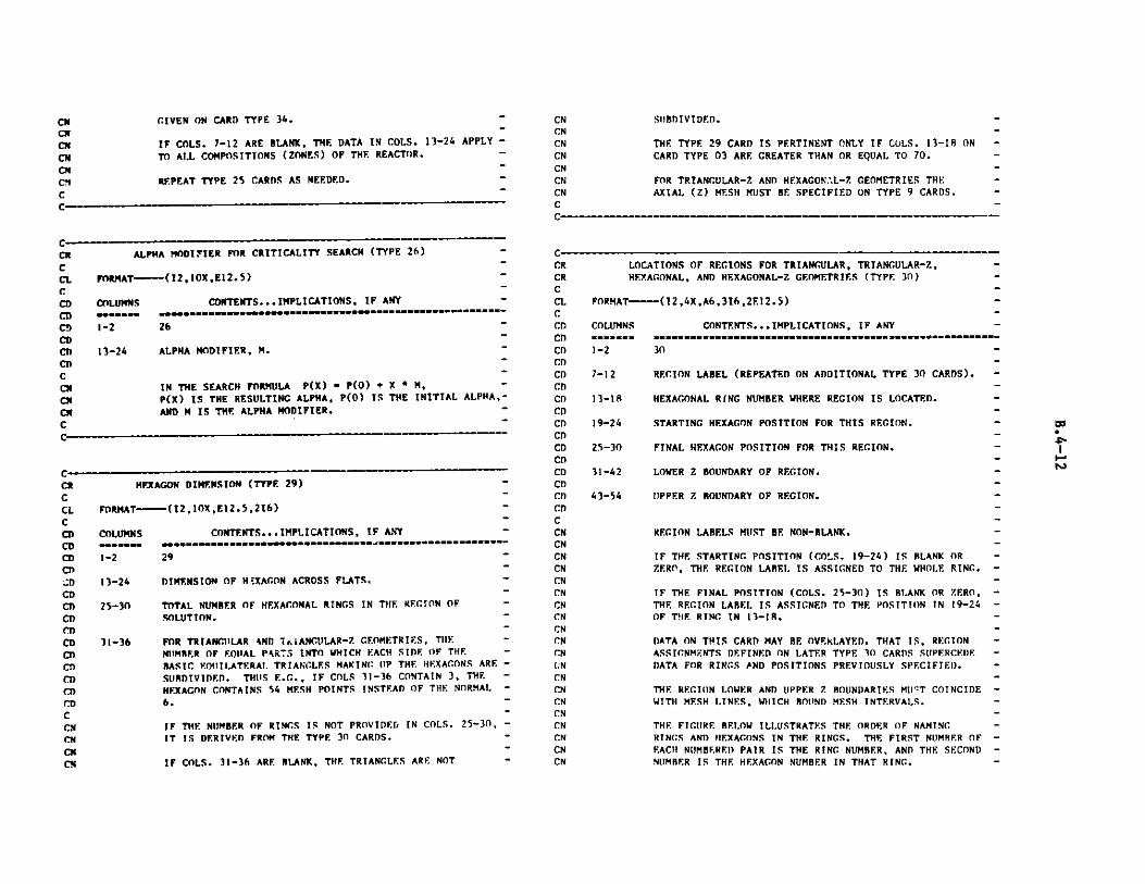
CNCNCNCNCNCNCNC
GIVEN ON CARD TYPE 34. -
IF COLS. 7-12 ARE BLANK, THE DATA IN COLS. 13-24 APPLY -
TO ALL COMPOSITIONS (ZONES) OF THE REACTOR.-
REPEAT TYPE 25 CARDS AS NEEDED. -
C ___-_-__
CCR ALPHA MODIFIER FOR CRITICALITY SEARCH (TYPE 26) -
CCL FORMAT----(I2,1OX,E12.5) -C ~CD COLUMNS CONTENTS... IMPLICATIONS, IF ANY -
CD s""" "* m""""""""""-"""""""""""""""""""""""""""""""""""""-"----
CD 1-2 26 -CDCD 13-24 ALPHA MODIFIER, M.CDCcm IN THE SEARCH FORMULA P(X) - P(O) + X * M, -
Ci P(X) IS THE RESULTING ALPHA, P(O) IS THE INITIAL ALPHA,-
Ci AND M IS THE ALPHA MODIFIER. -C -
C
wt OvAr DUTMWNUCN (TYPE 29) -
FORMAT---(12,1OX,E12.5,216
)
COLUMNS CONTENTS...IMPLICATIONS, IF ANY
1-2 29
13-24
25-30
31-36
DIMENSION OF H'XAGON ACROSS FLATS.
TOTAL NUMBER OF HEXAGONAL RINGS IN THF. REGION OF -SOLUTION. -
FOR TRIANGULAR AND TRIANGULAR-Z GF.OMETRIES, THE --
NIMRER OF EQUAL PAR'3 INTO WHICH EACH SIDE OF THE -BASIC EOItILATERAL. TRIANGLES MAKING IP THE HEXAGONS ARESUBDIVIDED. THUS E.G., IF COLS 31-36 CONTAIN 3, THE -
HEXAGON CONTAINS 54 MESH POINTS INSTEAD OF THE NORMAL -
6. -
IF THE NUMBER OF RINGS IS NOT PROVIDED IN COLS. 25-30, -TT IS DERIVED FROM THE TYPE 30 CARDS. -
IF COLS. 31-36 ARE BLANK, THE. TRIANGLES ARE NOT -
SUBDIVIDED.
THE TYPE 29 CARD IS PERTINENT ONLY IF COLS. 13-18 ONCARD TYPE 03 ARE GREATER THAN OR EQUAL TO 70.
FOR TRIANGULAR-Z AND HEXAGON.L-7 GEOMETRIES THEAXIAL (Z) MESH MUST BE SPECIFIED ON TYPE 9 CARDS.
C---------------------------------------------------------
I. - -- - - -
CRCRCCLCCDCDCDCDCDCDCDCDCDCICDCDCDCDCI)CDCCNCNCNCNCNCN
CNCNCNCNCNCNCNCNCNCNCNCNCNCN
LOCATIONS OF REGIONS FOR TRIANGULAR, TRIANGULAR-Z,HEXAGONAL, AND HEXAGONAL-Z GEOMETRIES (TYPE 30)
FORMAT----(12,4X,A6,316,2E12.5)
COLUMNS
1-2
7-12
13-18
19-24
25-30
31-42
43-54
CONTENTS...IMPLICATIONS, IF ANY -
30
REGION LABEL (REPEATED ON ADDITIONAL TYPE 30 CARDS). -
HEXAGONAL RING NUMBER WHERE REGION IS LOCATED. -
STARTING HEXAGON POSITION FOR THIS REGION.-
FINAL HEXAGON POSITION FOR THIS REGION. -
LOWER Z BOUNDARY OF REGION. I-
UPPER Z BOUNDARY OF REGION. -
REGION LABELS MUST BE NON-BLANK. -
IF THE STARTING POSITION (CO!S. 19-24) IS BLANK OR -ZERO, THE REGION LABEL. IS ASSIGNED TO THE WHOLE RING. -
IF THE FINAL POSITION (COLS. 25-30) IS BLANK OR ZERO, -THE REGION LABEL IS ASSIGNED TO THE POSITION IN 19-24 -OF THE RING IN 13-18.
DATA ON THIS CARD MAY BE OVFkKLAYED. THAT IS, REGION -ASSIGNMENTS DEFINED ON LATER TYPE 30 CARDS SUPERCE)E -DATA FOR RINGS AND POSITIONS PREVIOUSLY SPECIFIED. -
THE REGION LOWER AND UPPER Z BOUNDARIES M11T COINCIDE -WITH MESH LTNES, WHICH BOUND MESH INTERVALS. -
THE FIGURE BELOW ILLUSTRATES THE ORDER OF NAMING -RINGS AND HEXAGONS IN THE RINGS. THE FIRST NUMBER OF -EACH NUMBF.REI) PAIR IS THE RING NUMBER, AND THE SECOND -NIMBER IS THE HEXAGON NUMBER IN THAT RING. -
Ol
""
cmCN
Cm
CNCN
C
CR
CCLCDCDCDCDCD
CDCDCDCDCDCDCDCDCD
CD
CDCnCci
CNCN
-""-"---""-"""" S
------
--
-

THE REGION OF SOLUTION DEPENDS ON THE VALUE IN COLS.13-18 ON CARD TYPE 03 AS FOLLOWS.
COLS. 13-18 ON CARD TYPE 03
807278707,
1 Ii.114116
G
CMC4CM
CM
CMCMCM
C,'CMcmcmCHCM
CN
CNCNC'
Cr
CN
CNCNCNCi
cm
CxCxCMCxCx
CN
CNCNM
Cyr
CxCxCxCHC
cmcm
CmCmCHCNCM
CM
REGION OF SOLUTION
ENTIRE FIGURE AS SHOWN BELOWIN THE 180 DEGREE SECTOR A-BIN THE 90 DEGREE SECTOR A-CIN THE 60 DEGREE SECTOR A-DIN THE 120 DEGREE SECTOR A-EENTIRE FIGURE AS SHOWN BELOWIN THE 60 DEGREE SECTOR F-CIN THE 120 DEGREE SECTOR F-G
E
*
*
C
*
* * *
-3,5 - -3,4 - -3,3 -
-3,6 - -2,3 - -2,2 - -3,2 -
"3,7 - -2,4 - -1,1 - -2,1 - -3,1 -
-3,8 -2,5 - -2,6 - -3,12-
-,9- -3,10- -3,11 *
"3,9 " "3,10" -3,11-
*
*
*
* * *
*
*
ALTHOUGH THE REGIONS OF SOLUTION DIFFER FOR THETRIANGULAR AND HEXAGONAL GEOMETRY MODELS, TYPE 30CARDS COMPOSED FOR TRIANGULAR GEOMETRY MODELS CANBE USED FOR HEXAGONAL GEOMETRY MODELS.
AL
L
- CD
- CD
CD- CD
- CD
- C
- CN
- CN
- CN
- CN
- CN
- CN
- CN
CN
- CN
-C
C- CR
- CR
- C
- CL
- C
- CD
- CD
- CDF - CD
- CD
CD- CD
- Cn
- CD
- CD
- CI)- CD
A - CD- CD
- CI)- CD
so - CD
CD- CD- CD
CNCN
- CN
- CN
- CN
- CN
COLUMNS
1-2
7- 12
CONTENTS... IILICATIONS, IF ANY
--31-
BACKGROUND REGION NAME. -
ANY 'ORTION OF THE FACTOR NOT SPECIFIED ON THE -TYPE 30 CARDS WILL BE IN THE BACKGROUND REGION. -
IF THE BACKGROUND REGION NAME (COLS. 7-12) IS BLANK, -OR IF THERE IS NO TY?:? 31 CARD, THE BACKGROUND REGION -WILL AE ASSIGNED A REGION NUMBER O (ZERO). NOTE THAT -SOME CCC CODES EXCLUDE SUCH A REGION FROM THE REGION -OF SOLUTION, WHILE OTHER CCCC CODES MAY NOT ALLOW -ZERO REGION :rUMBERS. -
COMPOSITION AND GROUP DEPENDENT BUCKLING SPECIFICATIONS(TYPE 34)
FORMAT----(2,4X,A6,2(E12.5,216))
COLUMNS
1-2
7-12
11-24
25-30
11-36
37-48
4Q-54
55-60
CONTENTS...IMPLICATIONS, IF ANY
--34-
COMPOSITION LABEL. -
BUCKLING (R**2). -
HIGHER ENERGY BROAD GROUP NUMBER TO WHICH BUCKLING -IN COLS. 13-24 APPLIES. -
LOWER ENERGY BROAD GROUP NUMBER TO WHICH BUCKLING -IN COLS. 13-24 APPLIES. -
BUCKLING (B**2). -
HIGHER ENERGY BROAD GROUP NUMBER TO WHICH BUCKI.ING -IN COLS. 37-48 APPLIES. -
LOWER ENERGY BROAD GROUP NUMBER TO WHTCH BUCKL.ING -IN COLS. 37-48 APPLIES. -
IF THERE IS NO COMPOSITION LABEL (COLS. 7-12 ARE -BLANK), THE BUCKLINGS ON THIS CARD WILL APPLY TO -ALL COMPOSITIONS. -
IF NO "HIGHER-ENERGY GROUP NUMBER [S SUPPLIED IN -COLS. 25-30, THE BUCKLING GIVEN IN COLS. 13-24 APPLIES -
a"
*
*
*
w
C-
CRCRCCL
BACKGROUND REGION NAME FOR TRIANGULAR, TRIANGULAR-Z,HEXAGONAL. AND HEXAGONAL-Z GEOMETRIES (TYPE 31)
FORMAT---( 12,4X,A6)
C -
-

CDCDCDCDCDCmCXCXCXCXCXCXCXCXCXCXCXCXCXCXCXCX
CXCXCXCXCXCXCXCMCXCXCXCN
Cm
TO ALL ENERGY GROUPS. IF THERE IS A 'HIGHER-ENERGY -GROUP NUMBER' IN COLS. 25-30, BUT NO 'LOWER-ENERGY -GROUP NUMBER' IS SUPPLIED IN COLS. 31-36, THE BUCKLING -GIVEN IN COLS. 13-24 APPLIES TO THE "HIGHER-ENERGY -GROUP' ONLY. -
IF NO 'HIGHER-ENERGY GROUP NUMBER' IS SUPPLIED IN -COLS. 49-54, THE DATA IN COLS. 37-60 ARE IGNORED. IF -THERE IS A 'HIGHER-ENERGY GROUP NUMBER' IN COLS. 49-54,-BUT NO 'LOWER-ENERGY GROUP NUMBER' IN COLS. 55-60, -THE BUCKLING GIVEN IN COLS. 37-48 APPLIES TO THE'HIGNER-ENERGY GROUP' ONLY. -
BUCKLINGS CAN BE OVERLAYED. THAT IS, DUCKLINGS DEFINED -ON LATER TYPE 34 CARDS SUPERCEDE DATA FOR COMPOSITIONS -AND/OR ENERGY RANGES PREVIOUSLY DEFINED. THE EXCEPTION -TO THIS RULE IS THE SITUATION DESCRIBED IN THE PRE- -CEDING PARAGRAPHS WHERE DATA IS SPECIFICALLY IGNORED. -
EXAMPLE 34 ** .001 1 3 .002 4 7 -34 COMPI .003 1 5 -34 COMPI .004 3 -34 COMP2 .005 -
THIS EXAMPLE IS IN FREE-FORMAT - ** IMPLIES A BLANK -LABEL. COMPOSITION COMPI IS BUCKLED .003 IN GROUPS -1-2, .004 IN GROUP 3, .003 IN GROUPS 4-5, .002 IN -GROUPS 6-7, AND ZERO IN ALL OTHER GROUPS. -COMPOSITION COMP2 IS BUCKLED .005 IN ALL GROUPS. ALL -OTHER COMPOSITIONS ARE BUCKLED .001 IN GROUPS 1-3, -.002 IN GROUPS 4-7 AND ZERO IN ALL OTHER GROUPS. -
WHEN ANY TYPE 34 CARDS EXIST, BUCKLINGS WILL NOT BE -CALCULATED FROM FINITE GEOMETRY DATA ON TYPE 12 CARDS. -
DIRECTIONAL DIFFUSION COEFFICIENT FACTOR SCHEME (TYPE 35) -
FORMAT----(12,4X,A6,6F6.2,216) -
COLUMNS CONTENTS... IMPLICATIONS, IF ANY -
1-2 35 -
7-12 DIRECTIONAL DIFFUSION COEFFICIENT FACTOR SCHEME LAUREL. -
13-1R FIRST DIMENSION DIFFUSION COEFFICIENT MULTIPLIER, Al. -
19-24 FIRST DIMENSION DIFFUSION COEFFICIENT ADDITIVE -
TERM, BI.--
25-30
31-36
SECOND DIMENSION DIFFUSION COEFFICIENT MULTIPLIER, A2.
SECOND DIMENSION DIFFUSION COEFFICIENT ADDITIVETERM, R2.
CDCD
CDCDCDCDCDCDCDCDCDCDCDCDCDCCNCNCNCNCNCNCNCNCNCNCNCNCNCNCNCNCNCNCNCNCNCNCNCNCNCNCNCNCNCNCNCNCNCNCNCNCNCN
37-42 THIRD DIMENSION DIFFUSION COEFFICIENT MULTIPLIER, A3.
43-48 THIRD DIMENSION DIFFUSION COEFFICIENT ADDITIVETERM, B3.
49-54 HIGHER ENERGY BROAD GROUP NUMBER TO WHICH DATA INCOLS. 13-48 APPLY.
55-60 LOWER ENERGY BROAD GROUP NUMBER TO WHICH DATA INCOLS. 13-48 APPLY.
IF MORE THAN ONE TYPE 35 CARD IS NEEDED FOR A GIVENDIFFUSION COEFFICIENT FACTOR SCHEME, THE LAREL INCOLS. 7-12 MUST BE REPEATED ON EACH ADDITIONAL CARD.
FIRST, SECOND AND THIRD DIMENSIONS REFER TO THEDIMENSIONS IN THE ORDER THEY ARE NAMED ON CARD TYPE 3.E.G. FOR R-Z GEOMETRY R IS THE FIRST DIMENSION, AND
Z IS THE SECOND.
THE FIRST DIMENSION DIFFUSION COEFFICIENT, D1, IS
CALCULATED FROM THE HOMOGENEOUS DIFFUSION COEFFICIENT,D, AS FOLLOWS:
DI - Al*D+B1
THE OTHER TWO DIMENSIONS ARE HANDLED IN A SIMILAR WAY.
IF THE "HIGHER ENERGY BROAD GROUP NUMBER" IS NOTPROVIDED (COLS. 49-54 ARE BLANK OR ZERO), THECONSTANTS SPECIFIED IN COLS. 13-48 WILL APPLY TO ALLBROAD GROUPS FOR THE PARTICULAR SCHEME.
IF THE "LOWER ENERGY BROAD GROUP NUMBER" IS NOTPROVIDED (COLS. 55-60 ARE BLANK OR ZERO), THECONS'. "TS SPECIFIED IN COLS. 13-48 WILL APPLY TO THE
HIGHER ENERGY BROAD GROUP NUMBER (COLS. 49-54) ONLY.
THE CONSTANTS DEFIaING A PARTICULAR SCHEME CAN BEO RELAYED. THAT IS, FACTORS DEFINED ON LATER TYPE 35CARD. SIIPERCEDE DATA FOR ENERGY RANGES PREVIOUSLYDEFINED.
DIRECTIONAL DIFFUSION COEFFICIENT FACTOR SCHEMES AREASSIGNED TO COMPOSITIONS ON TYPE 36 CARDS.
IF NO TYPE 36 CARDS ARE SUPPLIED, A,) ONLY ONE SCHEMEIS DEFINED (THE SAME LABEL APPEALS IN COLS. 7-12 OFAL!. TYPE 35 CARDS), THE FACTORS WILL BE USED IN ALL
C
to
CRCCLCCDCDCDCDCDCDCDCDCDCDCD

COMPOSITIONS.
IF NO TYPE 36 CARDS ARE SUPPLIED AND MORE THAN ONE
SCHEME IS DEFINED, THE FACTORS FOR THE FIRST DEFINED
SCHEME (I.E. THAT SCHEME LABEL WHICH APPEARS ON THE
FIRST TYPE 35 CARD) WILL BE USED IN ALL COMPOSITIONS.
THE CALCULATION OF TRANSVERSE LEAKAGE BY THE DIF3D
CODE WILL USE THE THIRD DIMENSION DIFFUSIONCOEFFICIENT FOR THE PSEUDO ABSORPTION,
D-B-SQUARED (A3*D+B3)*B**2REGARDLESS OF THE PROBLEM DIMENSIONS. V)THERCODES USING THE COMPXS FILE MAY BEHAVE DIFFERENTLY -
IT IS UP TO THE USER TO CHOOSE THE PROPER
COEFFICIENT TO MODIFY.
CmCmCHCxCHCmCNCNCNCMCHCNCHCCMC
DIRECTIONAL DIFFUSION COEFFICIENT FACTORS-COMPOSITION -
CORRESPONDENCE (TYPE 36)-
FORMAT-----(12,4X,11A6)-
COLUMNS CONTENTS... IMPLICATIONS, IF ANY-
1-2 36-
7-12 DIRECTIONAL DIFFUSIOrs COEFFICIENT FACTOR SCHEME LABEL -
(SEE CARD TYPE 35).-
13-'8 COMPOSITION TO WHICH DIFFUSION COEFFICIENT FACTORS ARE. -
ASSIGNED.
19-24 COMPOSITION TO WHICH DIFFUSION COEFFICIENT FACTORS ARE -
ASSIGNED.-
25-30 COMPOSITION TO WHICH DIFFUSION COEFFICIENT FACTORS ARE -
ASSIGNED.
31-36 COMPOSITION TO WHICH DIFFUSION COEFFICIENT FACTORS ARE -
ASSIGNED.-
37-42 COMPOSITION TO WHICH DIFFUSION COEFFICIENT FACTORS ARE -
ASSIGNED.
43-48 COMPOSITION TO WHICH DIFFUSION COEFFICIENT FACTORS ARE -
ASS SIGNED.
49-54 COMPOSITION TO WHICH DIFFUSION COEFrICIENT FACTORS ARE -
ASSIGNED.
55-60 COMPOSITION TO WHICH DIFFUSION COEFFICIENT FACTORS ARE -
61-66
67-72
CDCDCDCDCD
CDCDCCNCNCNCNCNCNCNCNCNCN
CNCNCNCNCNCNCNCNCNCNCNCNC
C---- -
CRCCLCCDCDCDCDCDCDCDuCDCDCT)CDCDC,)CDCu)
FISSION ENERGY CONVERSION FACTOR DATA (TYPE 37)
FORMAT-----(12,10X,3(A6,E12.5))
COLUMNS CONTENTS... IMPLICATIONS, IF ANY
1-2 37
13-18 COMPOSITION LABEL.
19-30 ENERGY CONVERSION FACTOR FOR THIS COMPOSITION(FISSIONS/WATT-SEC.).
31-36 COMPOSITION LABEL.
37-48 ENERGY CONVERSION FACTOR FOR THIS COMPOSITION(FISSIONS/WATT-SEC.).
49-54 COMPOSITION LABEL.
ASSIGNED.
COMPOSITION TO WHICH DIFFUSION COEFFICIENT FACTORS ARE -ASSIGNED.
COMPOSITION TO WHICH DIFFUSION COEFFICIENT FACTORS ARE -ASSIGNED.
IF MORE THAN ONE TYPE 36 CARD IS REQUIRED TO ASSIGN -GIVEN DIFFUSION COEFFICIENT FACTORS TO COMPOSITIONS, -THE LABEL IN COLS. 7-12 MUST BE REPEATED ON THE -ADDITIONAL CARDS.
IF NO TYPE 36 CARDS ARE SUPPLIED, AND ONLY ONE -DIRECTIONAL DIFFUSION COEFFICIENT FACTOR SCHEME IS -DEFINED (THE SAME LABEL APPEARS IN COLS. 7-12 OF ALL -TYPE 35 CARDS), THE FACTORS WILL BE USED IN ALL -COMPOSITIONS. -
IF NO TYPE 36 CARDS ARE SUPPLIED AND MORE THAN ONE -SCHEME IS DEFINED, THE FACTORS FOR THE FIRST DEFINED -SCHEME WILL BE USED IN ALL COMPOSITIONS. -
IF NO COMPOSITIONS ARE DEFINED IN COLS. 13-72, .THE -SCHEME IDENTIFIED BY THE LABEL IN COLS. 7-12 WILL BE -USED FOR ALL COMPOSITIONS. -
THE SCHEME-COMPOSITION CORRESPONDENCE DATA CAN BE -OVERLAYED. THAT IS, DATA GIVEN ON LATER TYPE 36 CARDS -SUPERCEDES DATA PREVIOUSLY DEFINED. -
CRCRCCLCCDCDCDCDCDCDCDCDCDCDCDCDCDCDCDCDCDCD
CDCDCDCDCDCDCDCDCDCD
C __
to"
UI

CDCDCDCCN
CNCNCMCNCNCNCNCNCNCNCNCNCMCNCNCNCNCN
C:NCNCMC-
CAPTURE ENERGY CONVERSION FACTOR DATA (TYPE 38) -
FORMAT-----(12,1OX,3(A6,E12.5))
COLUMNS CONTENTS... IMPLICATIONS, IF ANYmm=m* m i......... .. .........===============-
1-2 38
13-18 COMPOSITION LABEL.
19-30 ENERGY CONVERSION FACTOR FOR THIS COMPOSITION -
(CAPTURES/WATT-SEC.).
31-36 COMPOSITION LABEL. -
37-48 ENERGY CONVERSION FACTOR FOR THIS COMPOSITION -
(CAPTURES/WATT-SEC.).
49-54 COMPOSITION LAREL.
55-66 ENERGY CONVERSION FACTOR FOR THIS COMPOSITION -(CAPTURES/WATT-SEC.).
IF TYPE 37 OR TYPE 38 CARDS ARE PROVIDED FOR A -
CNCNCNCNCNCNCNCNCNCNCNCNCNCNCNCNCNCNCNCNC
A PARTICULAR COMPOSITION, THE ENERGY CONVERSIONFACTORS IN DATA SET ISOTXS WILL BE IGNORED FOR THATCOMPOSITION, AND THE DATA ON THE TYPE 37 AND TYPE 38CARDS WILL RE USED INSTEAD.
IF THE FIRST LABEL (COLS. 13-18) ON A TYPE 38 CARD ISBLANK, THE ASSOCIATED CONVERSION FACTOR WILL BEENTERED FOR ALL COMPOSITIONS.
IF COLS. 31-36 ARE BLANK THE DATA IN COLS. 37-66 ARENEGLECTED. IF COLS. 49-54 ARE BLANK THE DATA INCOLS. 55-66 ARE NEGLECTED.
DATA ON THIS CARD MAY BE OVERLAYED. THAT IS, FACTORSDEFINED ON LATER TYPE 38 CARDS SUPERCEDE DATA FORCOMPOSITIONS PREVIOUSLY SPECIFIED.
THE ENERGY CONVERSION FACTOR FOR ANY COMPOSITION NOTREFERENCED ON A TYPE 37 OR TYPE 38 CARD WILL BEDETERMINED FROM DATA IN ISOTXS.
55-66 ENERGY CONVERSION FACTOR FOR THIS COMPOSITION -
(FISSIONS/WATT-SEC.). -
IF TYPE 37 OR TYPE 38 CARDS ARE PROVIDED FOR A -
A PARTICULAR COMPOSITION, THE ENERGY CONVERSION -
FACTORS IN DATA SET ISOTXS WILL BE IGNORED FOR THAT -COMPOSITION, AND THE DATA ON THE TYPE 37 AND TYPE 38 -
CARDS WILL BE USED INSTEAD. -
IF THE FIRST LABEL (COLS. 13-18) ON A TYPE 37 CARD IS -
BLANK, THE ASSOCIATED CONVERSION FACTOR WILL BE -ENTERED FOR ALL COMPOSITIONS. -
IF COLS. 31-36 ARE BLANK THE DATA IN COLS. 37-66 ARE -
EGLECTED. IF COLS. 49-54 ARE BLANK THE DATA IN -
COLS. 55-66 ARE NEGLECTED. -
DATA ON THIS CARD MAY BE OVERLAYED. THAT IS, FACTORS -
DEFINED ON LATER TYPE 37 CARDS SUPERCEDE DATA FOR -
COMPOSITIONS PREVIOUSLY SPECIFIED. -
THE ENERGY CONVERSION FACTOR FOR ANY COMPOSITION NOT -
REFERENCED ON A TYPE 37 OR TYPE 38 CARD WILL BE -DETERMINED FROM DATA IN ISOTXS. -
CRCCLCCDCDCDCDCDCDCDCDCDCDCDCDCDCDCDCDCDCDCDCDCI)
CDCDCDCD
NUCLIDE SET ASSIGNMENTS (TYPE 39)
FORMAT-----(12,4X, 1 1A6)
COLUMNS
1-2
7-12
13-18
19-24
25-30
31-36
37-42
CONTENTS... IMPLICATIONS, IF ANY
39
NUCLIDE SET LABEL.
TSOTOPE TO BE ASSIGNED TO THIS NUCLIDE SET. -
ISOTOPE TO BE
ISOTOPE TO BE
ISOTOPE TO BEISOTOPE TO BE
ASSIGNED
ASSIGNED
ASSIGNED
ASSIGNED
TO
TO
TO
TO
THIS
THIS
THIS
THIS
NUCLIDE
NUCLIDE
NUCLIDE
NUCLIDE
SET.
SET.
SET.
SET.
43-48 ISOTOPE TO RE ASSIGNED TO THIS NICLIDE SET.
49-54
55-60
61-66
ISOTOPE TO RE
ISOTOPE TO BE
ISOTOPE TO BE
ASSIGNED
ASSIGNED
ASSIGNED
TO THIS
TO THIS
TO THIS
NICLIDE
NUCLIDE
NUCLIDE
SET.
SET.
SET.
67-72 ISOTOPE TO BE ASSIGNED TO THIS NUCLIDE SET.
C-_____
, .. . . - . - - .-
CRCCLCCDCDCDCDCDCDCDCDcnCDCDCDCDCDCDCDCDCDCCN
-
--.-
- a'

NUCLIDE SET ASSIGNMENTS ARE OPTIONAL. THEIR USE MAY -REDUCE TEF SIZE OF THE CCCC ATOM DENSITY FILE (ZNATDN) -AND, THEREFORE, THE RUNNING TIME FOR CROSS SECTION -HOMOGENIZATION. -
ALL ISOTOPES USED IN A PARTICULAR ZONE OR A -PARTICULAR SUBZONE MUST BE ASSIGNED TO THE SAME -NUCLIDE SET. -
WHEN NO TYPE 39 CARDS ARE PROVIDED, ALL ISOTOPES ARE -ASSIGNED TO A SINGLE NUCLIDE SET.
SOURCE EDiT AND SYNTHESIS TRIAL FUNCTION SOURCESPECIFICATION (TYNE -3)
FORMAT---(12,4X,416)
COLUMNS CONTENTS... IMPLICATIONS, IF ANY
1-2 40 -
7-12 EDIT FLAG FOR POINTWISE INHOMOCENEOUS SOURCE0, NO EDITS (DEFAULT).1, PRINT EDITS.2, WRITE EDITS TO AUXILIARY OUTPUT FILE.3, WRITE EDITS TO BOTH PRINT AND AUXILIARY OUTPUT
FILE.
13-18 RTFLUX FILE VERSION NUMBER FOR A SYNTHESIS TRIALFUNCTION SOURCE.
S(X,Y,Z,G)-D(X,Y,ZG)*FLUX(X,Y,Z,G)WHERE D IS A DIFFUSION COFFFICIENT AND FLUX IS A FLUX(OR ADJOINT FLUX) FROM AN INPUT RTFLUX (OR ATFLUX)FILE. USE A NEGATIVE VALUE FOR ATFLUX. SET TO ZEROWHEN ANOTHER TYPE OF SOURCE IS REQUIRED.
19-24 VERSION NUMBER OF GFODST FILE SPECIFYING COMPOSITIONDISTRIBUTION REOUIRE:) FOR A SYNTHESIS TRIAL FUNCTIONSOURCE. 0 OR 1 IMPLIES THE GEOMETRY DEFINED BY THECURRENT A.NIP3 DATASET. THIS PARAMETER IS USED ONLYWHEN THE FLUX FILE VERSION IN COLS. 13-18 IS .GE. 1.
25-30 WORD LENGTH PARAMETER FOR THE FIXSRC FILE SOURCEDISTRIBUTION. ON SINGLE-WORD-LENGTH MACHINES(E.G. CDC) THIS INPUT FIELD IS IGNORED. ON DOUBLE-WORD-LENGTH MACHINES A VALUE OF 1 WILL PRODUCE ASHORT-WORD (I.E. REA.*4) FILE, A VALUE OF 2 WILLPRODUCE A DOUBLE-WORD (I.E. REAL*8) FILE. THE 1)IF3DCODE REQUIRES A DOUBLE-WORD FILE ON DOUBLE-WORD-
CDCDC
CCNCNCNCNCNCNCNCNCNCNCNC
CRCRCCLCCDCDCDCDCDCDCDCDCDCDCDCDCDCDCDCDCDCDCDCDCDCDCDCDCDCDCDCDCDCDCDCD
LENGTH MACHINES. (DEFAULT.= 2 ON DOUBLE-WORD-LENGTHMACHINES)
NATURAL DECAY INHOMOCENEOUS SOURCE SPECIFICATIONS -(TYPE 41)
FORMAT----(12,4X,2(A6,E12.5,A6))
COLUMNS CONTENTS... IMPLICATIONS, IF ANY -
1-2 41
7-12
13-24
25-30
ISOTOPE LABEL
DECAY CONSTANT
SPECTRUM LABEL OF SPECTRUM TO BE USED WITH THISISOTOPE (SEE CARD TYPE 42)
CRCRCCLCCDCDCDCCDCDCDCDCDCDCDCDCDCDCDCDCDCCNCNCNCNCNCNCNCN
CNCNCN
CN
CNC
SOURCE SPECTRUM DATA (TYPE 42) -
FORMAT----(12,4X,A6,5E12.5) -
COLUMNS CONTENTS... IMPLICATIONS, IF ANY ---:a-. -..--.--...........................
31-36 ISOTOPE LABEL -
37-48 DECAY CONSTANT -
49-54 SPECTRUM LABEL OF SPECTRUM TO BE USED WITH THIS -ISOTOPE (SEE CARD TYPE 42) -
WHEN THERE ARE TYPE 41 CARDS A FIXSRC FILE WILL BE -CREATED CONTAINING THE DISTRIBUTED SOURCE -
S(X,Y,Z,G) - SUM OVER ISOTOPES (I) OF -SCHI(G,I)*DC(I)*ATND(XY,Z,I) -
WHERE SCHI IS AN ISOTOPE SOURCE SPECTRUM (SEE THE TYPE -42 CARDS), DC IS THE DECAY CONSTANT AND ATND IS THE -ISOTOPE NUMBER DENSITY. -
AS MANY TYPE 41 CARDS SHOULD BE PROVIDED AS ARE -NECESSARY TO SPECIFY ALL ISOTOPES REQUIRED. -
WHEN THE SPECTRUM LABEL IS BLANK THE SOURCE WILL BE -COMPUTED WITH THE SPECTRUM EQUAL TO 1.0 IN ALL GROUPS. -
C
CRCCLCCDCD
C- - -- -_ -- ------ --- --- ---- M-- - - .M -- - M- M - r- - - -
C--------_ ------------ - - - - - - -
0
I--r
v

1-2
7-12
13-24
25--36
37-48
49-60
61-72
CDCDCDCDCDCDCDCDCDCDCDCDCDCCNCNCNCNCNCNCNCNCNCNCNCNCNCNC
GRAPHICS OUTPUT CONTROL (TYPE 43) -
FORMAT----(12,4X,16,3E12.4,316) -
COLUMNS CONTENTS...IMPLICATIONS, IF ANY1- 43 ---------- "------.....................-.- -----
1-2 43 -
GRAPHICS OUTPUT SENTINEL FOR MAP
0...NO GRAPHICS (DEFAULT)
1...GENERATE MAP
HEIGHT OF GRAPHICS OUTPUT FIELD (DEFAUILT=11.O INCHES)
WIDTH OF GRAPHICS OUTPUT FIELD (DEFAULT-11.O INCHES)
FOR TRIANGULAR AND HEXAGONAL GEOMETRIES - THIS FIELD
CONTAINS THE FLAT-TO-FLAT DISTANCE ACROSS EACH
HEXAGON, IN INCHES (DEFAULT - 0.5 INCHES)
FOR ORTHOGONAL GEOMETRIES - THOS FIELD CONTAINS THE
CRCCLCCDCDCD)CD
42
SPECTRUM LABEL
GROUP MULTIPLIER (SPECTRUM), FIRST GROUP.
GROUP MULTIPLIER (SPECTRUM), NEXT GROUP.
GROUP MULTIPLIER (SPECTRUM), NEXT GROUP.
GROUP MULTIPLIER (SPECTRUM), NEXT GROUP.
GROUP MULTIPLIER (SPECTRUM), NEXT GROUP.
AS MANY TYPE 42 CARDS, FIVE ENERGY GROUPS PER CARD,
SHOULD BE PROVIDED AS ARE NECESSARY TO SPECIFY ALL THE
SPECTRA NEEDED FOR THE NATURAL DECAY SOURCECALCULATION. THE FIRST TYPE 42 CARD MUST HAVE ANON-BLANK SPECTRUM LABEL. A REPEATED SPECTRUM LABELIMPLIES A CONTINUATION OF THE LAST CARD WITH THE SAME
LABEL. A BLANK SPECTRUM LABEL IMPLIES A CONTINUATION
OF THE SPECTRUM ON THE PREVIOUS TYPE 42 CARD.
WHEN THE NUMBER OF DATA FOR A PARTICULAR SPECTRUM IS
LESS THAN THE TOTAL NUMBER OF ENERGY GROUPS, THE
REMAINING ELEMENTS OF THE SPECTRUM ARE SET TO ZERO.
WHEN THE NUMBER OF DATA IS GREATER THAN THE NUMBER
OF GROUPS THE SURPLUS ELEMENTS ARE IGNORED.
ASSIGNMENT OF REGIONS TO CONTROL. ROD BANKS (TYPE 44) -
FORMAT-----(T 2,4X , 1 1 A6) -
COLUMNS CONTENTS... IMPLICATIONS, IF ANY -
1-2 44-
CDCDCCDCDCDCDCDCDCDCDCDCCNCNCNCNCNCNCNCNCNCNCN
CNCNCNCNCNCN
CNCNCN
CNCNCNCNCNCNCNCNCNC
MINIMUM REDUCTION ALLOWED FOR LABELS (DEFAULT - 0.5). -SEE THE NOTE BELOW.
49-54 PRINTER PLOTTER SENTINEL - HEXAGONAL MAP ONLY -1...FLAT-TO-FLAT HEXAGON DIMENSION " 8 ROWS -2... FLAT-TO-FLAT HEXAGON DIMENSION - 6 ROWS (DEFAULT) -
55-60 MAXIMUM NO. OF ROWS IN PRINTER-PLOTTER FIELD - -HEXAGONAL MAP ONLY (DEFAULT - 48) -
61-66 MAXIMUM NO. OF PRINT COLUMNS IN PRINTER-PLOTTER FIELD -- HEXAGONAL MAP ONLY (DEFAULT - 130) -
THE GRAPHICS OPTION MAY NOT BE AVAILABLE IN ALL -VERSIONS OF THE INPUT PROCESSOR GNIP4C. -
THIS CARD CONTROLS THE FORMAT OF THE PRINTER-PLOTTER -OUTPUT FOR HEXAGONAL MAPS BUT DOES NOT ACTUALLY -TRIGGER THE PRINTER MAP. THAT IS DONE BY A SENTINEL -ON THE TYPE 02 CARD. THIS CARD HAS NO EFFECT ON THE -PRINTER-PLOTTER MAP OF ORTHOGONAL GEOMETRY MODELS. -
FOR TRIANGULAR AND HEXAGONAL GEOMETRIES THE SCALE -OF THE PLOT IS DETERMINED BY THE FLAT-TO-FLAT DISTANCE -IN COLS. 37-48. THE SIZE OF THE GRAPHICS PAGE IS SET -BY THE DATA IN COLS. 13-36. THE CODE GENERATES AS -MANY PAGES OF GRAPHICS OUTPUT AS IT TAKES TO COVER THE -ENTIRE MAP. LABELS ARE CENTERED IN EACH HEXAGON, AND -THE CHARACTER SIZE IS A FIXED FRACTION (1/8) OF THE -FLAT-TO-FLAT DISTANCE. -
FOR ORTHOGONAL GEOMETRIES THE SCALE OF THE PLOT IS -SET BY THE CODE SO THAT THE ENTIRE MAP IS FORCED -TO FIT IN A SINGLE GRAPHICS PAGE. THE MAXIMUM -SIZE OF THE GRAPHICS PAGE IS SET BY THE DATA IN -COLS. 13-36. LABELS WITH 0.1 INCH CHARACTER HEIGHT -ARE PLACE IN REGIONS AS LONG AS THERE IS ROOM. IF THE -REGION IS TOO SMALL, THE LABEL IS REDUCED IN SIZE. IFTO FIT IN THE REGION THE LABEL SIZE MUST BE REDUCED -BY A FACTOR SMALLER THAN THE NUMBER TN COLS. 37-48 -
NO LABEL IS DRAWN. WHEN THE NUMBER IN COLS. 37-48 -IS GREATER THAN 1.0 NO LABELS ARE DRAWN. -
C----
CRCCLCCDCDCDCDCDCDCDCDCDCDCDCDCDCDCDC!)co
7-12
13-24
25-36
37-4h
C--__ M N Y M w Y Y M YM I M Y M Y Y
i M l M Y Y Y Y Y Y M M
US"
-N
-

CDCDCDCDCDCDCDCDCDCDCDCDCDCDCDCDCDCDCDCDCDCDCDCDCDCDCDCDCDCD
CDCDCDCDCDCDCDCDCDCDCDCD
CCHCm
CM
CMCNcm
7-12 CONTROL ROD BANK LABEL (REPEATED ON ADDITIONALTYPE 44 CARDS IF NECESSARY).
13-18 REGION LABEL OR AREA LABEL DEFINING REGION(S)AT T"E TIP OF THE MOVEABLE PORTION OF THE ROD(S) INTHE SPECIFIED CONTROL ROD BANK.
19-24 RECIOh LABEL OR AREA LABEL DEFINING REGION(S)AT THE TIP OF THE MOVEABLE PORTION OF THE ROD(S) INTHE SPECIFIED CONTROL ROD RANK.
25-30 REGION LABEL OR AREA LABEL DEFINING REGION(S)AT THE TIP OF THE MOVEABLE PORTION OF THE ROD(S) INTHE SPECIFIED CONTROL ROD RANK.
31-36 REGION LABEL OR AREA LABEL DEFINING REGION(S)AT THE TIP OF THE MOVEABLE PORTION OF THE ROD(S) INTHE SPECIFIED CONTROL ROD BANK.
37-42 REGION LABEL OR AREA LABEL DEFINING REGION(S)AT THE TIP OF THE MOVEABLE PORTION OF THE ROD(S) INTHE SPECIFIED CONTROL ROD RANK.
43-48 REGION LABEL OR AREA LABEL DEFINING REGION(S)AT THE TIP OF THE MOVEABLE PORTION OF THE ROD(S) INTHE SPECIFIED CONTROL ROD BANK.
49-54 REGION LABEL OR AREA LABEL DEFINING REGION(S)AT THE TIP OF THE MOVEABLE PORTION OF THE ROD(S) INTHE SPECIFIED CONTROL ROD BANK.
55-60 REGION LABEL OR AREA LABEL DEFINING REGION(S)AT THE TIP OF THE MOVEABLE PORTION OF THE ROD(S) INTHE SPECIFIED CONTROL ROD BANK.
61-66 REGION LABEL OR AREA LABEL DEFINING REGION(S)AT THE TIP OF THE MOVEABLE PORTION OF THE ROD(S) INTHE SPECIFIED CONTROL ROD BANK.
67-72 REGION LABEL OR AREA LABEL DEFINING REGION(S)AT THE TIP OF THE MOVEABLE PORTION OF THE ROD(S) INTHE SPECIFIED CONTROL ROD BANK.
ALL REGIONS IN A ROD CHANNEL ABOVE THE ROD TIPMOVE TOGETHER. ALL REGIONS BELOW THE TIP ARESTATIONARY. AND ARE REPLACED BY ROD REGIONS AS THEROD MOVES DOWN. THE TOPMOST REGION IN THE RODEXPANDS AS THE ROD MOVES DOWN FROM ITS INITIALPOSITION. THE REGION JUST BELOW THE INITIAL ROD-TIPPOSITION EXPANDS AS THE ROD MOVES UP FROM ITSORIGINAL POSITION.
THE LOWER BOUNDARY OF ALL ROD-TIP REGIONS WHICH DEFINEROLrS ASSIGNED TO A PARTICULAR CONTROL ROD BANK MUST
CNCSC.C,CN
C.
CS
CsC,CSC,Cti
C.
CyCN
CS
Cti
CSCACsC\C.
CXCS
CSCC\
Cti
C,C,CtN
CtiC\Cti
C
CNCxC,CN
Cti
CN,CN t
C,
CNS
C,
CN(:N
C.CS
Cti
CtiCN
C
c ------
CEOF
HE AT THlE SAME AXIAL POSITION. "AXIAL" REFERS TO THE -7.-DIMENSION IN R7., XYZ, AND flEX-%., AND TO THE Y -
DIMENSION IN XY. THUS FOR THE (R-Z E.G.) GEOMETRY -
PICTURED BELOW, -
------------ ---- -------------
I I I I I -I I R2 I I Rh I CR21 I -
I I I I I I -I I-------I CR11 I------I-------I -
I I I I I -I I R3 I I CR22 1 -I I I I 1 -
R RI I------I------l R7 I------ I -
I I I I -I I R4 I CR12 I I CR23 I -I I I I I I -I I-- - | - - i- - - - - - - -
I I I I I -I I R5 I Cl I RR I C2 I -
I I I I I I ----------------------- -------
THE FOLLOWING TYPE 44 CARDS (GIVEN IN FREE FORMAT -STYLE INPUT) WOULD RESULT IN A FATAL ERROR -
44 BANK! CR12 CR22 -
WHEREAS -
44 BANK CR12 CR23 -
WOULD BE ACCEPTABLE. ALSO, A ROD BANK MAY NOT HE -SPECIFIED USING MORE THAN ONE REGION IN A PARTICULAR -
VERTICAL CHANNEL. THUS -
44 BANK! CR22 CR23 -
WOULD LEAD TO A FATAL INPUT ERROR. -
NOTE THAT SINCE IT MUST BE ASSUMED THAT A CONTROL ROD -BANK WILL BE. MOVED DURING THE COURSE OF A PROBLEM, -
AT I.EAST ONE REGION MUST BE DEFINED BELOW EACh REGION -SPECIFIED IN COLS. 13-72. THIS, THE FOLLOWING TYPE -44 CART) WOULD NOT HE ACCEPTABLE FOR THE GEOMETRY GIVEN -
ABOVE -44 BANK Cl -
AN AREA LABEL IN COLS. 13-72 IMPLIES AI.1. TILE REGIONS -ASSIGNED TO THAT AREA. AREAS ARE DEFINED ON THE -TYPE 07 CARD OF DATASET A.NIP3. -
TILE FIRST BLANK REGION LABEL ENCOUNTERED TERMINATES -READING OF THE DATA ON THAT PARTICULAR TYPE 44 CARD. -
NOTF THAT A BLANK CONTROL ROD BANK .ABEL IS ACCEPTAB.E.-
w
to
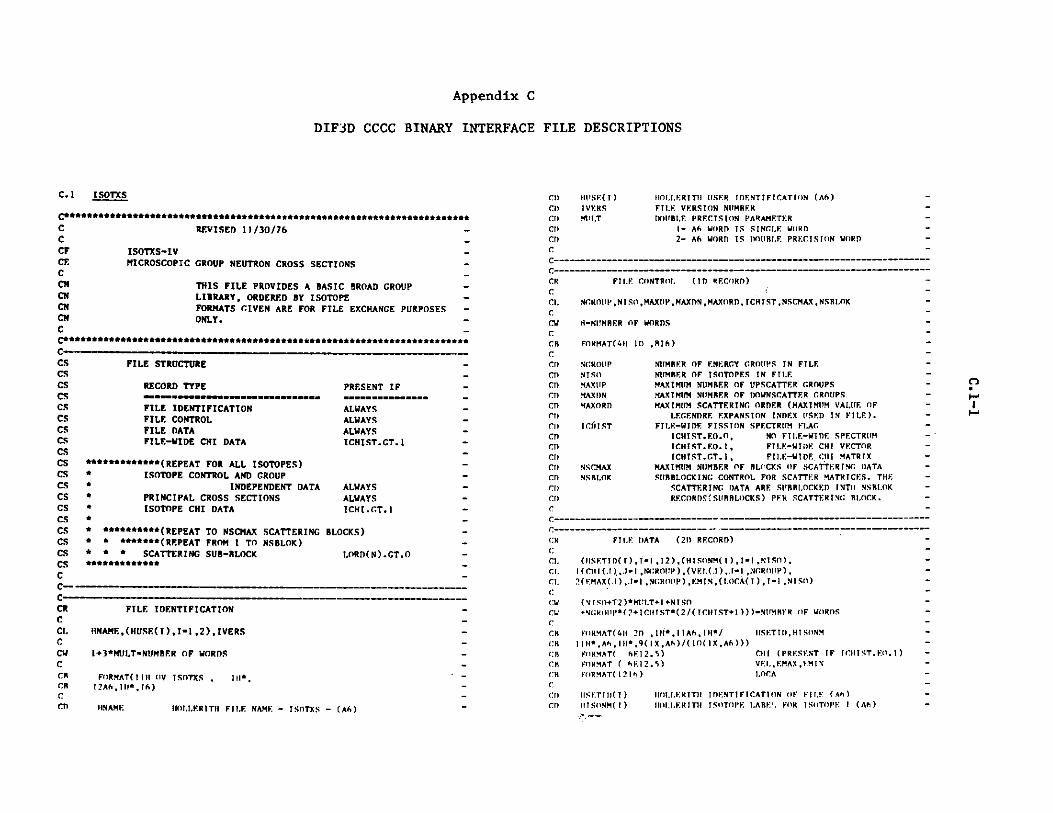
Appendix C
DIF3D CCCC BINARY INTERFACE FILE DESCRIPTIONS
C.1 ISOTXS
C************************************** ***M * ******* ******
C REVISED 11 /30/76 -CCF ISOTXS-IVCE MICROSCOPIC GROUP NEUTRON CROSS SECTIONS -CCN THIS FILE PROVIDES A BASIC BROAD GROUP -CM LIBRARY, ORDERED BY ISOTOPE -CM FORMATS GIVEN ARE FOR FILE EXCHANGE PURPOSES -CM ONLY.CC*************************************SEU******************************CSCS FILE STRUCTURE -CS -_
CS RECORD TYPE PRESENT IFCS .mmmmmmmm.mmmmmmmmm.........m. _CS FILE IDENTIFICATION ALWAYS -CS FILE CONTROL ALWAYS -CS FILE DATA ALWAYSCS FILE-WIDE CHI DATA ICHIST.GT.1 -CSCS ************(REPEAT FOR ALL ISOTOPES) -CS * ISOTOPE CONTROL AND GROUP -CS * INDEPENDENT DATA ALWAYSCS * PRINCIPAL CROSS SECTIONS ALWAYS -CS * ISOTOPE CHI DATA ICHI.GT.1 -CS * -CS * **********(REPEAT TO NSCMAX SCATTERING BLOCKS) -CS * * *******(REPEAT FROM I TO NSBLOK) -CS * * * SCATTERING SUB-BLOCK LORD(N).GT.O -CS ***** ** -_
C -
c -- - - M -
CRCCLC
CUCCRCR
CCD
FILE IDENTIFICATION
HNAME,(HUSE(I),I.I ,2),IVERS
1+3*MULT.NUMBER OF WORDS
FORMAT(I I I OV ISOTXS , IH*,I2A(,+II*.!6)
IINAME HOI.I.RITH FIIE NAME - ISOTXS - (C)
C!)CI)C!!C!)C!)C
!IUSE(i)
RIVERS411 .T
IIO!.I.ERITlI ISER IDENTIFICATION (A)FII.E VERSION NIIMRERIDE!RLF. PRECISION PARAMETER
1- A6 WORD IS SINGLE WORD2- A6 WORD IS !E!!R.E PRECISION WORD
C -------------------------------------------
CR FIL.E CONTROl. (ID RF.CORD) -
C-CI. NGROIIP,NISO,MAXIP,MAXDN,MAXORD, tCHISTNSCMAX.NSRI.OK -CCW M-N!MRF.R OF WORDSCC R FORMAT(411 I0 , 8I6)C -CI) NCRO!!P NUMBER OF ENERGY GROUPS IN FILE-C!) NTSO NIMRF.R OF ISOTOPES IN FILECD MAXUP MAXIMUM NUMBER OF UPSCATTER GROUPS -C!) MAXDN MAX IMUM NIMRER OF DOWNSCATTER GROUPS -CD MAXORD MAXIMUM SCATTERING ORDER (MAXIMUM VALUE OF -CI) LF.GENDRE EXPANSION INDEX USED IN FILE). -Cl) ICHIST FTLE-WIDE FISSION SPECTRUM FLAG -CD ICHI ST. EO.O , NO F I.E-WIDE. SPECTRUM -C!) TCHIST.EO.1, FILE-WIDE CHI VECTOR -C!) ICHTST.CT.1, FILE-WIDE CIII MATRIX -C1) NSCMAX MAXIMUM NUMBER OF BLOCKS OF SCATTERING DATA -CD NSRI.OK SI!RRLOCKING CONTROL FOR SCATTER MATRICES. THE -CI) SCATTERING DATA ARE SUBRI.OCKED INTO NSRI.OK -CI) RECORD? SI!RRLOCKS) PER SCATTERING ROCK. -C
C--------------------------- ---------------------
CR FTI!.E DATA (2D RECORD)-C-CI. (ISETTD(T),1-1,12),(HISONM(I),I-!,NTSO), -CI. I (CU T(. )..!-I ,NGR O!P) ,(vEI.(.1) ,.1-1 , 'NGR!T!P) ,C!. 2(VMAX(.),.1-1 ,N(;ROP),E.MIN,(I.OCA(I ),I-1 , NSO)
CW (NiO+T2)*MIT.T+I+NISO
CW 4N1R()111*(2+CHIST*(2/(TCIIrST+1)))-NIMIIFR OF WORDSCCM FORMAT(4H 2!) ,Il*,I IA6,II!*/ .SETIOlISONM -
CM I III.*Ah, IIH*,9(IX,A6)/(IC( IXA6)))CR FORMAT( hF.12.5) CHI (PRESENT IF ICHI T.FO.I) -
CR FORMAT ( 6E.12.5) VEI.,EMAX, EMIN -Cl! FORMAT(! 21h) .OCA
CI) ISET I!)(I) O!.!.ERITU IDENTIFICATION OF FI.E ( A) -C!) Ill SONM( I) IOI..ER ITI! I SOTOPE I.ARE'. FOR ISOTOPE I (A) -
n

CHI(J)VEL(J)EMAX(J)ENINLOCA(I)
FILE-WIDE FISSION SPECTRUM(PRESENT IF ICHIST.EQ.1)MEAN NEUTRON VELOCITY IN GROI'P J (CM/SEC)MAXIMUM ENERGY BOUND OF GROUP J (EV)MINIMUM ENERGY BOUND OF SET (EV)NUMBER OF RECORDS TO BE SKIPPED TO READ DATA FOR
ISOTOPE I. LOCA(1)=0
FILE-HIDE CHI DATA (3D RECORD)
PRESENT IF ICHIST.GT.1
((CHI(K,J),K-1 ,ICHIST),J-l ,NROUP),(ISSPEC(I),'-1l,NGROUP)
NGROUP.*(ICNIST+1)-NUMBER OF WORDS
FORMAT(4H 3D , 5E12.5/(6E12.5)) CHIFORMAT(1216) ISSPEC
CHI(K,J) FRACTION OF NEUTRONS EMITTED INTO GROUP J AS ARESULT OF FISSION IN ANY GROUP,USING SPr.. ?UM K
ISSPEC(I) ISSPEC(I)-K IMPLIES THAT SPECTRUM K IS USEDTO CALCULATE MISSION SPECTRUM FROM FISSIONIN GROUP I
ISOTOPE CONTROL AND GROUP INDEPENDENT DATA (4D RECORD)
HABSID,HIDENT,HMAT,AMASS,EFISS,ECAPT,TEMPSIGPOT,ADENS,KBR,ICHI,1IFIS,IALF,INP,IN2N,IND,INT,LTOT,LTRN,ISTRPD,2(IDSCT(N),N-1,NSCMAX),(LORD(N),N-!,NSCMAX),3((JRAND(J,N),J-1,NGROUP),N-1 ,NSCMAX),4((IJJ(J,N),J-1,NGROUP),N-1 ,NSCMAX)
3*MULT+I7+NSCMAX*(2*NGROUP+2)-NUMBER Of WORDS
FORMAT(4H 4D ,3(IX,A6)/ 6E12.5/1(1216))
HABSID HOLLERITH ABSOLUTE ISOTOPE LABEL - SAME FOR ALU.
HIDENT
HMATAMASSEFISSECAPTTEMPSIGPOT
ADENS
VERSIONS OF THE SAME ISOTOPE IN FILE (A6)IDENTIFIER OF LItRARY FROM WHICH BASIC DATA
CAME(E.G. ENDF/B) (A6)ISOTOPE IDENTIFICATION (E.G. ENDF/B MAT NO.) (A6)GRAM ATOMIC WEIGHTTOTAL THERMAL ENERGY YIELD/FISSION (W.SEC/FISS)TOTAL THERMAL ENERGY YIELD/CAPTURE (W.SEC/CAPT)ISOTOPE TEMPERATURE (DEGREES KELVIN)AVERAGE EFFECTIVE POTENTIAL SCATTERING IN
RESONANCE RANGE (BARNS/ATOM)DENSITY OF ISOTOPE IN MIXTURE IN WHICH ISOTOPE
CROSS SECTIONS WERE GENERATED (A/BARN-CM)
CDCDCDCDCDCDCC
- CD
- CD
CD- CD
- CD
- CD
- CD
CD
CD
- CD
- CD
- CD
CD- CD
CD- CD
- CD
- CD
- CD
- CD
- CD
- CD
- CD
- CD
- CD
- CD
- CD
- CD
CD- CD
- CD
- CD
- CD- CD- CI)
- CD
- CD
- CD
- CD- CD
CD- CD- CD- CD
CD- C )- CD
- CD
- CD
- CD- CD
- CD
- CD
CD
KBR
ICHI
IFIS
IALF
INP
IN2N
IND
INT
LTOT
LTRN
ISTRPD
IDSCT(N)
LORD(N)
ISOTOPE CLASSIFICATION0-UNDEFINED1-FISSILE2-FERTILE3-OTHER ACTINIDE4-FISSION PRODUCT5-STRUCTURE6-COOLANT7-CONTROL
ISOTOPE FISSION SPECTRUM FLAGICHI.EQ.0, USE FILE-WIDE CHIICHI.EQ.1, ISOTOPE CHI VF.'TORICHI.GT.1, ISOTOPE CHI MATRIX
(N,F) CROSS SECTION FLAGIFIS-O, NO FISSION DATA IN PRINCIPAL CROSS
SECTION RECORD-1, FISSION DATA PRESENT IN PRINCIPAL
CROSS SECTION RECORD(N,ALPHA) CROSS SECTION FLAG
SAME OPTIONS AS IFIS(N,P) CROSS SECTION FLAG
SAME OPTIONS AS IFIS(N,2N) CROSS SECTION FLAG
SAME OPTIONS AS IFIS(N,D) CROSS SECTION FLAG
SAME OPTIONS AS IFIS(N,T) CROSS SECTION FLAG
SAME OPTIONS AS IFISNUMBER OF MOMENTS OF TOTAL CROSS SECTION PROVIDED
IN PRINCIPAL CROSS SECTIONS RECORDNUMBER OF MOMENTS OF TRANSPORT CROSS SECTION
PROVIDED IN PRINCIPAL CROSS SECTIONS RECORDNUMBER OF COORDINATE DIRECTIONS FOR WHICH
COORDINATE DEPENDENT TRANSPORT CROSS SECTIONSARE GIVEN. IF ISTRPD-0, NO COORDINATE DEPENi3NTTRANSPORT CROSS SECTIONS ARE GIVEN.
SCATTERING MATRIX TYPE IDENTIFICATION FORSCATTERING BLOCK N. SIGNIFICANT ONLY IFLORD(N).GT.OIDSCT(N)-000 + NN, TOTAL SCATTERING, (SUM OF
ELASTIC,INELASTIC, AND N,2N SCATTERINGMATRIX TERMS).
-100 + NN, ELASTIC SCATTERING-200 + NN, INELASTIC SCATTERING-300 + NN, (N,2N) SCATTERING,---SEE
NOTE BELOW-WHERE NN IS THE LEGENDRE EXPANSION INDEX OF THEFIRST MATRIX IN BLOCK N
NUMBER OF SCATTERING ORDERS IN BLOCK N. IFLORD(N)-O, THIS BLOCK TS NOT PRESENT FOR THISISOTOPE. IF NN IS THE VALUE TAKEN FROMIDSCT(N), THEN THE MATRICES IN THIS BLOCKHAVE LEG.NDRE EXPANSION INDICES OF NNNN+1,NN+2,... ,NN+LORD(N)-1
CRCCCCCLCCvCCaCBCCDCDCDCDCDCC
CRCCLCLCLCLCLCCVCCRCRCCDCDCDCDCDCDCDCDCDCDCDCDCD
C)
"
h..a
N

JBAND(JN) NUMBER OF GROUPS THAT SCATTER INTO GROUP J,INCLUDING SELF-SCATTER, IN SCATTERING BLOCK N.
IF JBAND(J,N)0, NO SCATTER DATA IS PRESENT IN
BLOCK NIJJ(JN) POSITION OF IN-GROUP SCATTERING CROSS SECTION IN
SCATTERING DATA FOR GROUP J, SCATTERING BLOCK
NCOUNTED FROM THE FIRST WORD OF GROUP J DATA.
IF JBAND(J,N).NE.O THE, IJJ(J,N) MUST SATISFYTHE RELATION 1.LE.IJJ(J,N).LE.JBAND(J,N)
NOTE- FOR N,2N SCATTER, THE MATRIX CONTAINS TERMS,SCAT(J TO C), WHICH ARE EMISSSION (PRODICTION)-BASED, I.E., ARE DEFINED SUCH THAT MACROSCOPIC
SCAT(J TO C) TIMES THE FLUX IN GROUP J GIVESTHE RATE OF EMISSION (PRODUCTION) OF NEUTRONS
INTO CROUP G.
PRINCIPAL CROSS SECMTONS (SD RECORD)
((STRPL(JL),Jm1 .NGROUP),Le1,LTRN),t((STOTL(JL),J1 ,NGROUP)L" l,LTOT),(SNGAM(J),JI1 ,NGROUP),2(SFIS(J),J"1,NGROUP),(SNUTOT(J),J-1,NGROUP),3(CDISO(J),J*I ,NGROUP),(SNALF(J),J1 GROUPUP,
4(SNP(J).J-1,NROUP),(SN2N(J),J1I ,NGROUP),S(SND(J),JmI ,NGROUP),(SNT(J),J"1 ,NGROUP)6((STRPD(JI),JINROUP),I*IISTRPD)
(I+LTRN+LTOT+IALF+INP+IN2N+IND+INT+ISTRPD+2*IFIS+ICNI"(2/(ICI+)))*NCROUP"NUMER OF WORDS
CDCnCCNCNCNCNCNCN
CNC
STRPD(J,I) COORDINATE DIRECTION I TRANSPORT CROSS SECTION(PRESENT IF ISTRPD.GT.O)
NOTE - THE PRINCIPAL N,2N CROSS SECTION SN2N(J)
IS DEFINED AS THE N,2N REACTION CROSS SECTION,I.E., SUCH THAT MACROSCOPIC SN2N(J) TIMES THEFLUX IN GROITP J GIVES THE RATE AT WHICH N,2N
REACTIONS OCCUR IN GROUP J. THUS, FOR N,2NSCATTERING, SN2N(J) - 0.5*(SUM OF SCAT(J TO G)SUMMED OVER ALL G).
CDCDCD
CDCD
CDCDC)CNC)CDCDCDCDCDcm
- CR- C
- CC
CL
C
. C
. CRCR
- C_ CD
. CD
. CD
. CD
. CD_ C_ CI
C
FORMAT(4H SD , 5E12.S/(6E12.5)) LENGTH OF LIST AS ABOVE -
STRPL(J.L) PL WEIGHTED TRANSPORT CROSS SECTION-THE FIRST ELEMENT OF ARRAY STRPL IS THE -
CURRENT (P1) WEIGHTED TRANSPORT CROSS SECTION -
THE LEGENDRE EXPANSION COEFFICIENT FACTOR (2L+1)-
IS NOT INCLUDED IN STRPL(Jt).STOTPt(J.L) P1. WEIGHTED TOTAL CROSS SECTION -
THE FIRST ELEMENT OF ARRAY STOTPL IS THE -
FLUX (PO) WEIGHTED TOTAL CROSS SECTION -
THE LEGENDRE EXPANSION COEFFICIENT FACTOR (2L+I)-
IS NOT INCLUDED IN STOTPL(J.L). -SNGA(J) (NCAMMA)SFIS(J) (NF) (PRESENT IF IFIS.CT.O)F.
SNIITOT(J) TOTAL NEUTRON YIELD/FISSION (PRESENT IF IFIS.GT.O)-
CHISc(J) ISOTOPE CHI (PRESENT IF ICHI.EQ.1)SNALF(J) (NALPHA) (PRESENT IF IALF.GT.O) -
SNP(J) (N.P) (PRESENT IF INP.CT.O) -
SN2N(J) (N,2N) (PRESENT IF IN2N.CT.O) --- SEE -
NOTE REL-----SND(J) (N.D) (PRESENT IF IND.GT.O) -
SNT(J) (N.T) (PRESENT IF INT.GT.O)
CRCCCCCLCCCCCCCCCCCCCCCCCCwCCRC
CDCD
ISOTOPE CHI DATA (6D RECORD)
PRESENT IF ICHI.GT.1
((CHIISO(K,J),K-1,ICHI),J"1,NGROUP),(ISOPEC(I), I1,NGROUP)
NGROUP*(ICHI+1)"NUMBER OF WORDS
FORMAT(4H 6D , 5E12.5/(6E12.5)) CHIISOFORMAT(1216) ISOPEC
CHIISO(K,J) FRACTION OF NEUTRONS EMITTED INTO GROUP J AS ARESULT OF FISSION IN ANY GROUP,USING SPECTRUM
ISOPEC(I) ISOPEC(I)-K IMPLIES THAT SPECTRUM K IS USEDTO CALCULATE EMISSION SPECTRUM FROM FISSIONIN GROUP I
SCATTERING SUB-BLOCK (7D RECORD)
PRESENT IF LORD(N).GT.O
((SCAT(KL),K-1 ,KAX),L-1 ,LORDN)
KMAX-SUM OVER J OF JBAND(J,N) WITHIN THE J-GROUP RANGE OF THISSUB-BLOCK. IF M IS THE INDEX OF THE SUB-BLOCK, THE J-GROUPRANGE CONTAINED WITHIN THIS SUlB-BLOCK ISJL-(M-1)*((NGROUP-1)/NSBLG.K+1)+I TO JU-MINO(NGROUP,JUP),WHERE JUP-M*((NGROUP-1)/NSBLOK +1).
LORDN-LORD(N)N IS THE INDEX FOR THE LOOP OVER NSCMAX (SEE FILE STRUCTURE)
KMAX*LORDN-NUMBER OF WORDS
FORMAT(4H 7D , 5E12.5/(6E12.5))
SCAT(K,L) SCATTERING MATRIX OF SCATTERING ORDER L, FORREACTION TYPE IDENTIFIED BY IDSCT(N) FOR THIS
C
cRCCLCLCLCLCLCLCLCCDCaCCQCCDCDCDCDCDCDCDCDCDCDCDCD
CDCDCDCDCDCDCD
K-n"
C-
C

BLOCK. JBAND(J,N) VALUES FOR SCATTERING INTO -GROUP J ARE STORED AT LOCATIONS K-SUM FROM 1 -T) (J-I) OF JBAND(JN) PLUS I TO K-1+JBAND(JN).-THE SUM IS ZERO WHEN J-l. J-TO-J SCATTER IS -THE IJJ(J,N)-TH ENTRY IN THE RANGE JBAND(J,N). -VALUES ARE STORED IN THE ORDER (J+JUP), -(J+JUP-I),...,(J+),J,(J-),...,(J-JDN), -WHERE JUP-IJJ(J,N)-l AND JDN-JBAND)(J,N)-IJJ(J,N)-
CEOF
C.2 CEODST
C*************************s****************************************
C REVISED 11/30/76 -CCF GEODST - IV -CCE GEOMETRY DESCRIPTION -Cc...... ao*eeee*e.e* ************** .*****..************eeoo ***o
CR FILE IDENTIFICATION (OV RECO D) -C _CL KNAME.(HUSE(I),I-1.2),IVERSCCW 1.3 *MILTCCD HIOAME HOL.rRITH FILE NAME - GEODST - (A6)CD HOUSE HOLLERITH USER IDENTIFICATION (A6) -CD RIVERS FILE VERSION NUMBER -CD PRLT D)UBLE PRECISION PARAMETERCD 1- A6 WORD IS SINGLE WORD -CD 2- A6 WORD IS DOUBLE PRECISION WORD -C -CC -- -- -M
FILE SPECIFICATIONS (ID RECORD) -
ICOMNZONE ,NREC.N7.CL.,4CINTI ,NCINTJ.NCINTK.NINTI ,NINTJ ,NINTK, IMBI,-IMB2,JMB1,JMB2,KMB1,KMB2.NRS,NRCSNIBCSNZWBBNTRIAG,NRASSNTHPT,-(NOP(I)I-1,4) -7
27 -
[GO"
CDCDCDCDCDCDCDCDC
GEOMETRY 0- POINT (FUNDAMENTAL MODE)1- SLAB2- CYLINDER3- SPHERE6- X-Y7- R-Z
CDCDCDCDCDCDCDCDCDCDCDCDCDCDCDCDCDCDCDCDCDCDCDCDCDCDCDCDCDCDCDCDCDCDCDCDCDCDCDCDCDCDCCCCCCCCCCCCCCCCCDCDCD
8- THETA-R -9- UNIFORM TRIANGULAR -10- HEXAGONAL ( MESH POINT IN EACH -
HEXAGONAL ELEMENT) -11- R-THETA -12- R-THETA-Z -13- R-THETA-ALPHA -14- X-Y-Z -15- THETA-R-Z -16- THETA-R-ALPHA17- UNIFORM TRIANGULAR-Z1R- HEXAGON-Z (MESH POINTS AS IN 10 -
ABOVE) -NUMBER OF ZONES (EACH HOMOGENEOUS IN NEUTRONICS-PROBLEM - A ZONE CONTAINS ONE OR MORE REGIONS) -NUMBER OF REGIONS -NUMBER OF ZONE CLASSIFICATIONS (EDIT PURPOSES) -NUMBER OF FIRST DIMENSION COARSE MESH INTERVALS-NUMBER OF SECOND DIMENSION COARSE MESH -
INTERVALS. NCINTJ.EQ.1 FOR ONE DIMENSIONAL -CASE.
NUMBER OF THIRD DIMENSION COARSE MESH INTERVALS-NCINTK.EQ.1 FOR ONE AND TWO DIMENSIONAL -CASES. -
NUMBER OF FIRST DIMENSION FINE MESH INTERVALS -NUMBER OF SECOND DIMENSION FINE MESH INTERVALS -
NINTJ.EQ.1 FOR ONE DIMENSIONAL CASE. -NUMBER OF THIRD DIMENSION FINE MESH INTERVALS -
NINTK.EQ.1 FOR ONE AND TWO DIMENSION CASES.-FIRST BOUNDARY ON FIRST DIMENSION -
0 - ZERO FLUX (DIFFUSION)I - REFLECTED -2 - EXTRAPOLATED (DIFFUSION - DEL PHI/PHI -
- -C/D WHERE C IS GIVEN AS BNDC BELOW -AND D IS THE GROUP DIFFUSION CONSTANT, -TRANSPORT - NO RETURN). -
3 - REPEATING (PERIODIC) WITH OPPOSITE FACE-4 - REPEATING (PERIODIC) WITH NEXT ADJACENT-
FACE.5 - INVERTED REPEATING ALONG THIS FACE. -
(180 DEGREE ROTATION) -6 - ISOTROPIC RETURN (TRANSPORT) -
I%
NOTE FOR REPEATING CONDITIONS (3,4,5) - LET II DENOTE FIRST-BOUNDARY ON FIRST DIMENSION, 12 THE SECOND BOUNDARY ON THE -FIRST DIMENSION, .11 THE FIRST BOUNDARY ON THE SECOND -DIMENSION, ETC. THEN THESE REPEATING BOUNDARY CONDITIONS -
ONLY APPLY TO BOUNDARIES 11,12,J1, AND 32. GOING IN ORDER -OF 11,31,12,J2, THE FIRST BOUNDARY WHICH IS INVOLVED -CARRIES THE DESIGNATOR DEFINING THE REPEATING CONDITION. -
IMB2.1MBIJMR2
LAST BOUNDARY ON FIRST DIMENSIONFIRST BOUNDARY ON SECOND DIMENSIONLAST BOUNDARY ON SECOND DIMENSION
NZONE
NREGNZCLNCINTINCINTJ
NC I NTK
NINTININTJ
NINTK
IMB!
CRC
CLCLC
CCDCDCDCDCDCD
-------
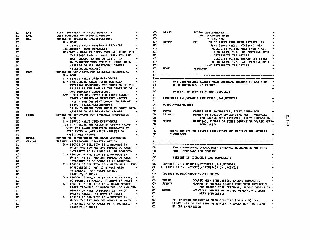
CDCDCDCDCDCDCDCDCDCDCDCDC
MaIiKMS2N'S
NRASS
NTHPT
REGION ASSIGNMENTS0- TO COARSE MESH
- Tn FINE MESHOR- ON OF FIRST FINE MESH INTERVAL IN
'ILAR GEOMETRIES. NTRIAG-2 ONLY.'vGLE(1,1) POINTS AWAY FROM FIRSTSION AXIS, I.E., NO INTERNAL MESHNTERSECTS THE ORIGIN.
-- LE(1,1) POINTS TOWARD THE FIRST.NSION AXIS, I.E., AN INTERNAL MESH
LINE INTERSECTS THE ORIGIN.RESERVED
CDCDCDCDCDCDCDCDCDCDCDCDCDCDCDCDCDCDCDCDCDCDCDCDCDCDCDCDCDCDCDCDCDCDCDCDCDCDCDCDCDCDCDCDCDCDCDCDCDCDCDCD
FIRST BOUNDARY ON THIRD DIMENSION -LAST BOUNDARY ON THIRD DIMENSION -NUMBER OF BUCKLING SPECIFICATIONS
0 - NONE- SINGLE VALUE APPLIES EVERYWHERE -
.EQ.NZONE- ZONE DEPENDENT -M*NZONE - DATA IS GIVEN OVER ALL ZONES FOR -
THE FIRST ENERGY GROUP, THEN FOR THE -NEXT GROUP, TO END OF LIST. IF -M.LT.NCROUP THEN THE M-TH GROUP DATA -APPLIES TO ALL ADDITIONAL GROUPS. -(2.LE.M.LE.NGROUP) -
NUMBER OF CONSTANTS FOR EXTERNAL BOUNDARIES -0 - NONE -I - SINGLE VALUE USED EVERYWHERE -6 - INDIVIDUAL VALUE GIVEN FOR EACH -
EXTERNAL BOUNDARY. THE ORDERING OF THE -VALUES IS THE SAME AS THE ORDERING OF -THE BOUNDARY CONDITIONS. -
6*M - SIX VALUES GIVEN FOR FIRST ENERGY -GROUP (ORDERED AS DESCRIBED ABOVE), -THEN 6 FOR THE NEXT GROUP, TO END OF -LIST. (2.LE.M.LE.NGROUP). -IF M.LT.NCROUP THEN THE M-TH GROUP DATA-APPLIES TO ALL REMAINING GROUPS. -
NUMBER OF CONSTANTS FOR INTERNAL BOUNDARIES -0 - NONE -1 - SINGLE VALUE USED EVERYWHERE -.GT.1 - VALUES ARE GIVEN BY ENERGY GROUP -
WITH NON-BLACK CONDITION INDICATED BY -ZERO ENTRY - LAST VALUE APPLIES TO -ADDITIONAL GROUPS -
NUMBER OF ZONES WHICH ARE BLACK ABSORBERS -TRIANGULAR/HEXAGONAL GEOMETRY OPTION -
0 - REGION OF SOLUTION IS A RHOMBUS IN -WHICH THE 1ST AND 2ND DIMENSION AXES -INTERSECT AT AN ANGLE OF 120 DEGREES. -
- REGION OF SOLUTION IS A RHOMBUS IN -WHICH THE 1ST AND 2ND DIMENSION AXES -INTERSECT AT AN ANGLE OF 60 IjECRS. -
2 - REGION OF SOLUTION IS A RECTANGLE. THE-BOUNDARIES II AND 12 BISECT MESH -TRIANGLES. SEE NThPT BELOW. -(IGOM-9,17 ONLY) -
3 - REGION OF SOLUTION IS AN EQUILATERAL, -60 DECREE TRIANGLE. (IGOM-9,17 ONLY) -4 - REGION OF SOLUTION IS A 30-60 DEGREE -RIGHT TRIANGLE IN WHICH THE 1ST AND 2ND-DIMENSTON AXES INTERSECT AT THE 30 -DECREE ANGLE. (ICOM-9,17 ONLY) -
5 - REGION OF SOLUTION IS A RHOMBUS IN -WHICH THE IST AND 2ND DIMENSION AXES -INTERSECT AT AN ANGLE OF 30 DEGREES. -(ICOM-9,17 ONLY) -
CRCRCCCCCLCCVCCDCDCDCDCDCCCCCCCCCRCRCCCCCLCLCCW
CCDCDCDCT)CI)CCCCCCC
ONE DIMENSIONAL COARSE MESH INTERVAL BOUNDARIES AND FINEMESH INTERVALS (2D RECORD)
PRESENT IF IGOM.GT.O AND IGOM.LE.3
(XMESH(I),I.1,NCBNDI),(IFINTS(I),I-1,NCINTI)
NCBNDI*MULT+NCINTI
XMESH COARSE MESH BOUNDARIES, FIRST DIMENSIONIFINTS NUMBER OF EOUALLY SPACED FINE MESH INTERVALS
NCBNDIPER COARSE MESH INTERVAL, FIRST DIMENSION. -
NCINTI+1, NUMBER OF FIRST DIMENSION COARSE MESH-BOUNDARIES -
UNITS ARE CM FOR LINEAR DIMENSIONS AND RADIANS FOR ANGULAR -DIMENSIONS
TWO DIMENSIONAL COARSE MESH INTERVAL BOUNDARIES AND FINE -MESH INTERVALS (3D RECORD)
PRESENT IF ICOM.CE.6 AND IGOM.LE.11 -
(XMESH(I),I-1,NCBNDI),(YMESH(J),J-1,NCBNDJ), -I(IFINTS(I),I-1,NCINTI),(JFINTS(J),J-1,NCINTJ)
(NCBNDI+NCBNDJ)*MULT+NCINTI+NCINTJ
YMESH COARSE MESH BOUNDARIES, SECOND DIMENSION -JFINTS NUMBER OF EQUALLY SPACED FINE MESH INTERVALS -
PER COARSE MESH INTERVAL, SECOND DIMENSION.-NCBNDJ NCINTJ+1, NUMBER OF SECOND DIMENSION COARSE -
MESH BOUNDARIES -
FOR UNIFORM-TRIANGULAR-MESH GEOMETRY (IGOM - 9) THE -LENGTH (L) OF THE SIDE OF A MESH TRIANGLE MUST BE GIVEN -BY THE EXPRESSION -
NCOP
NI BCS
NZWBBNTRIAG
C-
---
n"

L - 2.*(XMESH(2)-XMESH(l))/IFINTS(1) .FOR UNIFORM-HEXAGONAL-MESH GEOMETRY (IGOM 10) THEFLAT-TO-FLAT DISTANCE (FTF) ACROSS A MESH HEXAGON MUSTRE GIVEN BY THE EXPRESSION
FTF - (XMESH(2)-XMESH(1))/IFINTS(1)
C---
CRCCCCCLCCwCCSCSCCDCDC
CCccccccCCCCC-C-Cm
CccCCLCLCLCCL-CCDCD
CDCccccccccccccCCccC
GEOMETRY 'TA (SD RECORD)
PRESENT IF IGOM.GT.O OR NBS.GT.O
(VOLR(N),N-INREC),(BSQ(N),N1 ,'BS),(BNDC(N),N-I,NBCS),
(BNCI(N),N"1,NIBCS).((NZHRB(N),N-,NZWBB),(NZC(N),Nl,NZONE),(NZNR(N),NI ,NREG)
2*NREG+NBS.NBCS+NI BCS+NZWBB+N7.ONE
VOLR REGION VOLUMES (CC)BSQ BUCKLING (**2) VALUES (C**-2)MNDC BOUNDARY CONSTANTS (DEL PHI/PHI --C/D)MCI INTERNAL BLACK BOUNDARY CONSTANTSNZHBB ZONE NUMBERS WITH BLACK ABSORBER CONDITIONSN7C ZONE CLASSIFICATIONSN7.NR ZONE NUMBER ASSIGNED TO EACH REGION
REGION ASSIGNMENTS TO COARSE MESH INTERVALS (6D RECORD)
PRESENT IF IGOM.GT.O AND NRASS.EQ.O
((MR(I,J),I-1 ,NCINTI),J-1 ,NCINTJ)----NOTE STRUCTURE BELOW---
NCINTI*NCINTJ
DO I K-I ,NCINTKREAD(N) *LIST AS ABOVE*
MR REGION NUMBERS ASSIGNED TO COARSE MESHINTERVALS
THREE DIMENSIONAL COARSE MESH INTERVAL BOUNDARIES AND FINE -MESH INTERVALS (4D RECORD) -
PRESENT IF IGOM.GE.12 -
(XNESH(I),I-1,NCBNDI),(YMESH(J),J-1,NCBNDJ), -l(ZMESM(K),K"1,NCBNDK),(IFINTS(I),I-l,NCI!NTI), -2(JFINTS(J),J"1,NCINTJ),(KFINTS(K),K-1,NCINTK) -
(NCBNDI+NCBNDJ+NCBNDK)*MULT+NCINTI+NCINTJ+NCINTK
ZMESH COARSE MESH BOUNDARIES, THIRD DIMENSION -KFINTS NUMBER OF EQUALLY SACED FINE MESH INTERVALS -
PER COARSE. MESH INTERVAL, THIRD DIMENSION. -NCBNDK NCINTK+1, NUMBER OF THIRD DIMENSION COARSE MESH-
BOUNDARIES
FOR UNIFORM-TRIANGULAR-MESH GEOMETRY (IGOM 17) THE -LENGTH (L) OF THE SIDE OF A MESH TRIANGLE MUST BE GIVENBY THE EXPRESSION -
L - 2.'(XMESH(2)-XMESH(1))/IFINTS(1) . -FOR UNIFORM-HEXAGONAL-MESH GEOMETRY (ICON 18) THE -FLAT-TO-FLAT DISTANCE (FTF) ACROSS A MESH HEXAGON MUST -BE GIVEN BY THE EXPRESSION -
FTF - (XMESH(2)-XMESH())/IFINTS(1) -
C-
CR REGION ASSIGNMENTS TO FINE MESH INTERVALS (7D RECORD) -CCC PRESENT IF IGOM.GT.O AND NRASS.EQ.1CCL ((MR(I,J),I-I,NINTI),J-1,NINTJ)----NOTE STRUCTURE BELOW--- -CCw NIfI[*NINTJ -CCS DO 1 K-1,NINTKCS 1 READ(N) *LIST AS ABOVE* -CCD MR REGION NUMBERS ASSIGNED TO FINE MESH INTERVALS -CC--CEOF
C.3 NDXSRF
C*************************s**, ******************************************
C REVISED 11/30/76 -CCF NDXSRF-IV -CCF. NUCT 'DE DENSITY, DATA, CROSS SECTION REFERENCING -
C
C---- - -_- _ ------- ~ -_-
CR FILE IDENTIFICATIONCCl. HNAMF,(HISF.(I),I-1,2),IVERSCCw 1+3*MUILT-NIIMBER OF WORDSCCD IINAME HOLLERITH FILE NAME - NDXSRF - (A6) -
C
CRCCcCCLCLCLCa'CCDCDCDCDCDCDCDC
I-
I
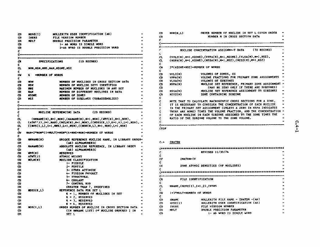
CQCDCDCDCDO
NUSE(I)IVERSORWLT
HOLLERITH USER IDENTIFICATION (A6)FILE VERSION NUMBERDOUBLE PRECISION PARAMETER
1- A6 WORD IS SINGLE WORD2-A6 WORD IS DOUBLE PRECISION WORD
CCCCR SPECIFICATIONS (ID RECORD)C -CL EN,NSNNNSNAN,NZONENSZCCd 6 "NUMBER OF WORDSCCD EN NUMBER OF NUCLIDES IN CROSS SECTION DATA -CD NSN NUMBER OF NUCLIDE SETS IDENTIFIEDCD wS MAXIMUM NUMBER OF NUCLIDES IN ANY SET -CD NAN NUMBER OF DIFFERENT NUCLIDES IN DATA -CD NZONE NUMBER OF ZONES -CD NSZ NUMBER OF SUBZWEES (SUBASSEMBLIES) -C -CCC NUCLIDE REFERENCING DATA (2D RECORD)CCL (NNNAME(N),Nl,NON),(NANAME(N),N-I,NON),(WPF(N),N-1,NON),CL (ATVT'J).Jal,NAN),(NCLN(N),Nm1,NON),((NDXS(K,L),Kil ,,),L-1,NSN),CL ((NfS(IL),I-,NNS),L-1,NSN),((NOR(N,L),N-1,MON),L-1,NSN)CC NAN+2*NON*(1+MULT)+NSN*(4+NNS+NON)-NUMBER OF WORDSCCD IWNAME(N) UNIQUE REFERENCE NUCLIDE NAME, IN LIBRARY ORDEICD (A6) ALPHANUMERICCD NANAME(N) ABSOLUTE NUCLIDE REFERENCE, IN LIBRARY ORDERCD (A6) ALPHANUMERICCD UPF(N) RESERVEDCD ATT(J) ATOMIC WEIGHTCD NCILN(N) NUCLIDE CLASSIFICATIONCD 1- FISSILECD 2- FERTILECD 3- OTHER ACTINIDECD 4- FISSION PRODUCTCD 5- STRUCTIrRAI.CD 6- COOLANTCD 7- CONTROL RODCD GREATER THAN 7, UNDEFINEDCD I)SXS(K,L) REFERENCE DATA FOR SET LCD K I, NUMBER OF NUCLIDES IN SETCD K " 2, RESERVEDCO K " 3, RESERVEDCD K " 4, RESERVEDCD HO)S(IL) ORDER NUMBER OF NUCLIDE IN CROSS SECTION DATACD (IN NNNAME LIST) Ow NUCLIDE ORDERED I INCD SET L
CD
CDC
NOR(N,L) ORDER NUMBER OF NUCLIDE IN SET L GIVEN ORDER -
NUMBER N IN CROSS SECTION DATA -
C-
Cr
CLCLCCWCCDCDCDCDCDCDCDCCCCCCC
NUCLIDE CONCENTRATION ASSIGNM+-T DATA (3D RECORD)
(VOLZ(N),Nm1,NZONE),(VFPA(N),NI ,NZONE),(VLSA(M),M=1 ,NSZ),(NSPA(N),Ni1,NZONE),(NSSA(M),MI1,NSZ),(NZSZ(M),M-1 ,NSZ)
3*(NZONE+NSZ).NUMBER OF WORDS
VOLZ(N) VOLUMES OF ZONES, CCVFPA(N) VOLUME FRACTIONS FOR PRIMARY ZONE ASSIGNMENTS
VLSA(M) VOLUMES OF SUBZONESNSPA(N) NUCLIDE SET REFERENCE, PRIMARY ZONE ASSIGNMENT
(MAY BE ZERO ONLY IF THERE ARE SUBZONES)
NSSA(M) NUCLIDE SET REFERENCE ASSIGNMENT TO SUBZONES
NZSZ(M) ZONE CONTAINING SUBZONE
NOTE THAT TO CALCULATE MACROSCOPIC CROSS SECTIONS FOR A ZONE,
IT IS NECESSARY TO CONSIDER THE CONCENTRATION OF EACH NUCLIDEIN THE PRIMARY SET ASSIGNMENT (UNLESS A ZERO IN NSPA INDICATES
THERE ARE NONE) TIMES THE VOLUME FRACTION, AND THE CONCENTRATION
OF EACH NUCLIDE IN EACH SUBZONE ASSIGNED TO THE ZONE TIMES THE
RATIO OF THE SUBZONE VOLUME TO THE ZONE VOLUME.CC
CEOF
C.4 ZNATDN
C******************************************************************
C REVISED 11/30/76
CCF ZNATDN-IVCCE ZONE ATOMIC DENSITIES (OF NUCLIDES) -C-
CRCCLCCVCCDCD
CDCT)CD
FILE IDENTIFICATION
HNAME,(HUSE(I),I -1,2),IVERS
1+3*MULT-NUMRER OF WORDS
NAME HOLLERITH FI.E NAME - 7NATDN -(A6)HIISE(I) HOLLERITH USER IDENTIFICATION (A6)
IVERS FILE VERSION NUMBERMILT DOUBLE PRECISION PARAMETER
1- A6 WORD IS SINGLE WORD
n-
...
-
:R-

2- A6 WORD IS DOUBLE PRECISION WORDCT)CCCCR SPECIFICATIONS (iD RECORD) .C -CL TIME.NCY ,NTZSZ ,NNS .NBLKAD.C -CW 5-NUMBER OF WORDS -CCD TIME REFERENCE REAL TIME, DAYS -CD NCY REFERENCE CYCLE NUMBER -CD NTZSZ NUMBER OF ZONES PLUS NUMBER OF SUBZONESCD !US MAXIMUM NUMBER OF NUCLIDES IN ANY SET -CD NILKAD NUMBER OF BLOCKS OF ATOM DENSITY DATA -C -CC -CR ZONE ATOMIC DENSITIES (OF NUCLIDES) (2D RECORD) -CCL ((ADF.N(N,J)N-1 ,NNS),J-JL,JU)--SEE STRUCTURE BELOW-- -C -Ca NNS'(JL - JU + 1) - NUMBER OF WORDS -C -CC D) I MI ,NBLKAD -CC I READ(N) *LIST AS ABOVE* .C -CC WITH M AS THE BLOCK INDEX, JL-(M-1)*((NTZSZ-1)/NBLKAD+1)+1 -CC AND JU-MINO(NTZSZ,JUP) WITH JUP-M*((NTZSZ-1)/NBLKAD + 1) -C .CD ADEN(NJ) ATOMIC DENSITY OF NUCLIDE ORDERED N IN THE -CD ASSOCIATED SET GIVEN IN ORDER FOR EACH ZONE -CD FOLLOWED IN ORDER FOR EACH SUBZONE -C -CCEOF
C.5 FIXSRC
ceaeeeeeeeeeeeeeeeeeeeeeeeeeeeeeeeeeeeeeeeeeeeeeeeeeeeeeeeeeeeeeeeeeeeee
C REVISED 11/30/76 -C -CF FIXSRC-IV -CE DISTRIBUTED AND SURFACE FIXED SOURCES -C -C..f"".............0.**.**..***fleeeeeeelfeeeeeeeeeeeeeeeeeeeeeeeeeeseen
CRCCLCa
FILE IDENTIFICATION
MNAME,(MUSE(I),I .2),IVERS
1+3'MULT-NUMBER OF WORDS
CCDCDCDCDCDCDC
NAMEHUSE(I)IVERSMULT
HOLLERITH FILE NAME - FIXSRC - (A6)HOLLERITH USER IDENTIFICATION (A6)FILE VERSION NUMBERDOUBLE PRECISION PARAMETER
1- A6 WORD IS SINGLE WORD2- A6 WORD IS DOUBLE PRECISION WORD
C ______
CRCCLCLCCuCCDCDCDCDCDCD
CDCDCDCDCDCDCDCDCDCDCDCDCDC
SPECIFICATIONS (1D RECORD)
ITYPE,NDIM,NGROUP,NINTI,NINTJ,NINTK,IDISTS,NDCOMP,NSCOMP,NEDGI,NEDGJ, NEDGK , NRLOK
13-NIIMBER OF WORDS
ITYPE TYPE SOURCE. 0-DIFFUSIONImSN
NDIT NUMBER OF DIMENSIONS
NGROUP NUMBER OF GROUPSNINTI NUMBER OF FIRST DIMENSION FINE MESH INTERVALSNINTJ NUMBER OF SECOND DIMENSION FINE MESH INTERVAL
NINTK NUMBER OF THIRD DIMENSION FINE MESH INTERVALSIDISTS DISTRIBUTED SOURCE FLAG.
NDCOMPNSCOMPNEDGINEDCJNEODCKNBLOK
0- NO DISTRIBUTED SOURCE GIVEN. -1- DISTRIBUTED SOURCE IS GIVEN. -
NUMBER OF DISTRIBUTED SOURCE COMPONENTS -NUMBER OF SURFACE SOURCE COMPONENTS -NUMBER OF FIRST DIMENSION BOUNDARY SOURCES -NUMBER OF SECOND DIMENSION BOUNDARY SOURCES -NUMBER OF THIRD DIMENSION BOUNDARY SOURCES -DATA BLOCKING FACTOR FOR DISTRIBUTED FIXED -
SOURCES IN MULTI-DIMENSIONS. (2ND DIMENSION -VARIABLE IS BLOCKED INTO NBLOK BLOCKS, -SEE 3D RECORD BELOW) -
n-
C-----C
CR ONE-DIMENSIONAL DISTRIBUTED FIXED SOURCE (2D RECORD) -
CCC PRESENT IF NDIM.EQ.1 AND IDISTS.NE.O -CCL ((QDIST(L,I),L-1,NDCOMP),I-1,NINTI)--NOTE STRUCTURE BELOW-- -C-CW NDCOMP*NINTI-NUMBER OF WORDSCC IX) I J-1,NGROUPC I READ (N) *LIST AS ABOVE*CCD QDIST(L,I) DISTRIBUTED SOURCE BY COMPONENT, INTERVAL, -CD AND GROUPC
--
S-

MULTI-DIMENSIONAL DISTRIBUTED FIXED SOURCE (3D RECORD)
PRESENT IF NDIM.CE.2 AND IDISTS.NE.O
((QDIST(I,J),I*1,NINTI),J-JL,JU) - SEE STRUCTURE BELOW----
NINTI*(JU - JL + 1) " NUMBER OF WORDS
La 1 N-I,9NGROUPDO I L 1,NDCOMPDO I KI1,NINTK00O "1 N, NBOKI READ (N) 'LIST AS ABOVE'
WITHIN AS THE BLOCK INDEX, JLIl+(N-1)*((NINTJ-1)/NBLOK +1)
AND JU.NINO(NINTJ,JUP) WHERE JUPM*((NINTJ-1)/NBLOK +1)
QDIST(I,J) DISTRIBUTED SOURCE AS DEFINED ABOVE
FIRST DIMENSION SURFACE SOURCE POINTERS (4D RECORD) -
PRESENT IF NEDCI.NE.O -
((ISPTRI(IJ),I.I ,NBDRYI),J"l,NINTJ)--NOTE STRUCTURE BELOW--- -
NBDRYI*NINTJ"NUMBER OF WORDS
DO 1 K*I,NINTK -1 READ (N) *LIST AS ABOVE' -
ISPTRI(I,J) ISPTRI(I,J) DENOTES THE INTERCEPT OF CHANNEL -
J,K WITH MESH BOUNDARY PLANE I. IF ISPTRI(I,J)-=), NO SURFACE SOURCE IS PRESENT AT THE -
INTERCEPT. IF ISPTRI(I,J)"M, THE MTH SURFACE -SOURCE SPECIFIED IN THE NEXT RECORD BELOW IS -
PRESENT AT THE INTERCEPT. -NSDRYI NINTI+1, NUMBER OF FIRST DIMENSION FINE MESH -
BOUNDARIES -
FIRST DIMENSION SURFACE SOURCES (5D RECORD)
PRESENT IF NEDCI.NE.O
(((OSURFI(MLN),MINEDCI),L-t.NSCOMP).N"1,NCROUP)
NEDCI* NGROUP*NSCOMPwNUMBER OF WORDS
QSURFI(M.L,N) FIRST DIMENSION BOUNDARY SOURCES BCOMPONENT, AND GROUP.
C-----
CRCccCCi.C
CCCCCCCCcccCCDC
Y BOUNDARY, -
SECOND DIMENSION SURFACE SOURCE POINTERS (6D RECORD)
PRESENT IF NDIM.GE.2 AND NEDGJ.NE.O
((ISPTRJ(I,J),I-1 ,NINTI),J-l,NBDRYJ)---NOTE STRUCTURE BELOW---
NINTI*NBDRYJ-NUMBER OF WORDS
DO I K1 ,NINTK
I READ (N) *LIST AS ABOVE*
ISPTRJ(I,J) ISPTRJ(1-J) DENOTES THE INTERCEPT OF CHANNEL
C_ -
-M
-
C-CRCCCCLCCWCCCCCD
CDCDCDCDCDCDCDCC--C-CRCCcCCL
C
CDCDCCC-CRCCCCC1.CCWCCCCCDCDCDCDCDCT)
NBDRYJ
CRCcCCC
C
CyCCCDCOCDCDCDCDCDCDC,-
CR
Ccc
CCLC
CCOCDO
C
n'
I,K WITH MESH BOUNDARY PLANE J. IF ISPTRJ(I.J)--0, NO SURFACE SOURCE IS PRESENT AT THE -INTERCEPT. IF ISPTRJ(IJ)-M, THE MTH SURFACE -SOURCE SPECIFIED IN THE NEXT RECORD BELOW ISPRESENT AT THE INTERCEPT. --NINTJ+1, NUMBER OF SECOND DIMENSION FINE MESH -BOUNDARIES
SECOND DIMENSION SURFACE SOUPCES (7D RECORD)
PRESENT IF NDIM.GE.2 AND NEDCJ.NE.O
(((QSURFJ(M,L,N),M-I ,NEDCJ),L-1 ,NSCOMP),N-l GROUPU)
NEDGJ*NGROUP*NSCOMP-NUMBER OF WORDS
QSURFJ(M,L,N) SECOND DIMENSION BOUNDARY SOURCES BY BOUNDARY -COMPONENT, AND GROUP
THIRD DIMENSION SURFACE SOURCE POINTERS (8D RECORD)
PRESENT IF NDIM.EQ.3 AND NEDGK.NE.O
((ISPTRK(I,J),I-1,NINTI),J-1,NINTJ)---NOTE STRUCTURE BELOW--- -
NINTI*NINTJ-NUMBER OF WORDS -
DO I Ka1,NBDRYK -I READ (N) *LIST AS ABOVE*
TSPTRK(I,J) ISPTRK(I,J) DENOTES THE INTERCEPT OF CHANNEL -I,J WITH MESH BOUNDARY PLANE K. IF ISPTRK(I,J)--0, NO SURFACE SOURCE IS PRESENT AT THE -INTERCEPT. IF ISPTRK(I,J)-M, THE MTH SURFACE -3OURCE SPECIFIED IN THE NEXT RECORD BELOW IS -PRESENT AT THE INTERCEPT.
MGM
C-
r_-M
M

CD NRDRYKCDC
=NINTK+I, NUMBER OF THIRD DIMENSION FINE MESHBOUNDARIES
THIRD DIMENSION SURFACE SOURCES (9D RECORD)
PRESENT IF NDIM.EQ.3 AND NEDCK.NE.O
(((QSURFK(M,L,N),MI ",NEDGK),L-1 ,NSCOMP),N-1 GROUPU)
NEDCK*NGROUP*NSCOMP"NUMBER OF WORDS
QSURFK(ML,N) THIRD DIMENSION BOUNDARY SOURCES BY BOUNDARY,COMPONENT, AND GROUP
CCF.OF
C.6 RTFLUX
C***********************************************************************
C REVISED 11/30/76 .CCF RTFLUX-IV .CE REGULAR TOTAL FLUXES .C
CD ORDER OF GROUPS IS ACCORDING TO DECREASINGCD ENERGY. NOTE THAT DOUBLE PRECISION FLUXES ARE
CD GIVEN WHEN MULT-2
CR FILE IDENTIFICATION-CCL INAME,(H1lSE(I),Ii1,2),IVERSCCW 1.3*PRLT-NUMBER OF WORDSC -CD HNAME HOLLERITH FILE NAME - RTFLUX - (A6) --CD NUSE(I) HOLLERITH USER IDENTIFICATION (A6)CD IVERS FILE VERSION NUMBER-CD PRJLT DOUBLE PRECISION PARAMETERCD 1- A6 WORD IS SINGLE WORD-CD 2- A6 WORD IS DOUBLE PRECISION WORD -C -C
CCDCDCDCDCDCDCDCDCDCDCDCDCDCDCDC
C M - -
CRCCCCCLCCWCCCCCCCCCCDCDc
CRCCCCCI.CCWCCCCCCCCCCC
NDIMGROUPNINTININTJNINTK
ITER
EFFKPOWERNBLOK
NUMBER OF DIMENSIONSNUMBER OF ENERGY GROUPS -NUMBER OF FIRST DIMENSION FINE MESH INTERVALS -NUMBER OF SECOND DIMENSION FINE MESH INTERVALS -NUMBER OF THIRD DIMENSION FINE MESH INTERVALS. -NINTK.EQ.1 IF NDIM.LE.2 -OUTER ITERATION NUMBER AT WHICH FLUX WAS -WRITTEN -EFFECTIVE MULTIPLICATION FACTOR -POWER IN WATTS TO WHICH FLUX IS NORMALIZED -DATA BLOCKING FACTOR -
IF NDIM.EQ.1 THE GROUP VARIABLE IS BLOCKED -INTO NBLOK BLOCKS (SEE 2D RECORD BELOW) -
IF NDIM.GE.2KTHE 2ND DIMENSION VARIABLE IS -BLOCKED INTO NBLOK BLOCKS (SEE 3D RECORD)-
ONE DIMENSIONAL REGULAR TOTAL FLUX (2D RECORD)
PRESENT IF NDIM.EQ.1
((FREG(I,J),I-1,NINTI),J-JL,JU)-----SEE STRUCTURE BELOW----- -
NINTI*(JU - JL + 1)*MULT - NUMBER OF WORDS -
DO I M- ,NBLOK
I READ(N) *LIST AS ABOVE*
WITH M AS THE BLOCK INDEX, JL-(M-1)*((NGROUP-1)/NRLOK+1)+1 -AND JU-MINO(NGROUP,JUP) WHERE JUP-M*((NGROUP-1)/NBLOK +1) -
FREG(I,J) ONE DIMENSIONAL REGULAR TOTAL FLUX BY INTERVAL -AND GROUP.
MULTI-DIMENSIONAL REGULAR TOTAL FLUX (3D RECORD) -
PRESENT IF NDIM.GE.2
((FREG(I,J),I-1,NINTI) ,J-JL,JU)-----SEE STRUCTURE BELOW----- -
NINTI*(JU - JL + 1)*MULT - NUMBER OF WORDS -
1)0 1 L-1 , NGROUP -) 1 K-1,NINTK
DO I M- ,NBLOKI READ(N) *LIST AS ABOVE* -
WITH M AS THE BLOCK INDEX, JL-(M-1)*((NINTJ-1)/NBLOK +1)+I -AND JII-MINO(NINTJ,JUP) WHERE .iUP-M*((NINTJ-1)/NBLOK +1) -
Cw ir.
CRCCCCCLC
CCDCDC
0n
CRCCLCCa
SPECIFICATIONS (ID RECORD)
NOYM,NCROUPNIMTININTJNINTKITEREFFKPOWERNBLOK
9 -NUMBER OF WORDS
c-------__
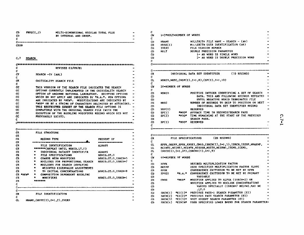
CCWCCDCDCDCl)CDCDCC---
MULTI-DIMENSIONAL REGULAR TOTAL FLUXBY INTERVAL AND GROUP.
C -- -
CEOR
C.7 SEARCH
C***************************,**********+ **** ***************************-
C REVISED 03/09/81 -C -CF SEARCH -IV (ANL) -C -CE CRITICALITY SEARCH FILE -CCC THIS VERSION OF THE SEARCH FILE INDICATES THE SEARCH -CC OPTIONS CURRENTLY IMPLEMENTED IN THE CRITICALITY SEARCH -CC OPTION AT ARGONNE NATIONAL LABORATORY. EXISTING OPTIONS -CC WHICH DO NOT APPLY ARE INDICATED BY *N.A.*. NEW OPTIONS -CC ARE INDICATED BY *NEW*. MODIFICATIONS ARE INDICATED BY -CC *MOD* OR BY A STRING OF CHARACTERS DELIMITED BY ASTERISKS. -CC THIS RESTRICTED SUBSET OF THE SEARCH FILE OPTIONS IS -CC COMPATIBLE WITH THE ORIGINAL SEARCH FILE (WITH THE -CC EXCEPTION OF THE BUCKLING MODIFIERS RECORD WHICH DID NOT -CC PREVIOUSLY EXIST). -C -C****+******************************************************************-
CCS FILE STRUCTURE -CS -CS RECORD TYPE PRESENT IF -CS - --------------------------------A----------------- -CS FILE IDENTIFICATION ALWAYS -CS *******(REPEAT UNTIL NSHID.LT. ) -CS * INDIVIDUAL DATASET IDENTIFIER ALWAYS -CS * FILE SPECIFICATIONS NSHID.GT.O -CS * COARSE MESH MODIFIERS NSHID.GT.O,ISRCH-5 -CS * NUCLIDES FOR PROPORTIONAL SEARCH NSHID.GT.O,ISRCH-1 -CS * NUCLIDES FOR SEARCH INVOLVING -CS * WEIGHTED EIGENVALUE ADJUSTMENTS -CS * TO INITIAL CONCENTRATIONS NSHID.GT.O,ISRCH-9 -CS *NEW* * COMPOSITION DEPENDENT BUCKLING -CS * MODIFIERS NSHID.GT.O,ISRCH=1 -CS *******C
r____-
CRCCL
CRCCLCCWCCDCDCDCDCDCDCDCDCDCDC
1+3*MULT-NUMBER OF WORDS
HNAME HOLLERITH FILE NAME - SEARCH - (A6) -HIJSE(I) HOLLERITH USER IDENTIFICATION (A6) -IVERS FILE VERSION NUMBERM1LT DOUBLE PRECISION PARAMETER -
I- A6 WORD IS SINGLE WORD -2- A6 WORD IS DOUBLE PRECISION WORD -
INDIVIDUAL DATA SET IDENTIFIER
NSHID,NREC,(NSP(I),I=1 ,8),(SP(I),I-1 ,1O)
20-NUMBER OF WORDS
NSHID
NREC
NSP( I)SP(1)SP(2)
SP(I)
*MOD**MOD*
*MOD*
(!D RECORD)
POSITIVE INTEGER IDENTIFYING A SET OF SEARCHDATA. THIS AND FOLLOWING RECORDS REPEATEDUNTIL NEGATIVE NSHID TERMINATES FILE
NUMBER OF RECORDS TO SKIP TO POSITION ON NEXTINDIVIDUAL DATA SET IDENTIFIER RECORD
RESERVEDAVERAGE TIME IN SECONDS/SEARCH PASSTIME REMAINING AT THE START OF THE PREVIOUSSEARCH PASS.RESERVED - I
C----
CRCCLCLCLCCWCCI)CDCDCDCDCDCDCDCDCDCI)CDCD
FTLE IDENTIFICATION
HNAME,(HIJSE(I),T-1 ,2),IVERS
FILE SPECIFIC
EFFK,DKEFF,EPSK,ENCINTI ,NCINTJ ,NCI?(NRCH(I),I-1,10),(
40-NUMBER OF WORDS
EFFKDKEFFEPSKEPSEI
CMOD
SRCH( I)SRCH(2)SRCH(3)SRCH(4)
*N.A.*
*MOn*
*EI(1)**EI(2)**EI(3)**EIMIN*
[CATIONS (2D RECORD) -
PSEI,CMOD,(SRCH(I),Im1,5),ISRCH,ISZOP,NMAXNP, -ITK,NISOSR,NSETS,NEIRNG, ITEND, ICEND, -:SRCH1(I),I-1,9) -
DESIRED MULTIPLICATION FACTOR -USER SPECIFIED MULTIPLICATION FACTOR SLOPE -CONVERGENCE CRITERION TO RE MET BY EFFK -
CONVERGENCE CRITERION TO RE MET BY PRIMARY -VARIABLE
MODIFIER APPLIED TO ALPHA (ISRCH'2) OR -MODIFIER APPLIED TO NUCLIDE CONCENTRATIONS -
VARIED SPECIALLY (ISRCI-7 BELOW),MAY BE -
.LT.0 -PREVIOUS PASS-1 SEARCH PARAMETER .(EI) -PREVIOUS PASS SEARCH PARAMETER (El) -MOST RECENT SEARCH PARAMETER (El) -uISER SPECIFIED LOWER BOUND FOR SEARCH PARAMETER-
CD FRF.(I,J)CD
r-

CDCDCDCDCDCDCDCDCDCDCDCDCDCDCDCDCDCDCDCDCDCDCDCDCDCDCDCDCDCDCDCDCDCI)CDCDCDCDCDCDCDCDCDCDCDCDCDCDCDCDCDCDCDCD
(El) -SRCH(5) *EIMAX* USER SPECIFIED UPPER BOUND FOR SEARCH PARAMETER-
(EI) -ISRCH TYPE OF SEARCH -
0- NOT DEFINED -1- BUCKLING SEARCH -2- ALPHA SEARCH -5- DIMENSION SEARCH -7- NUCLIDE CONCENTRATION SEARCH BY -
PROPORTIONAL ADJUSTMENTS OF SELECTED -INITIAL CONCENTRATIONS -
*N.A.* 9- NUCLIDE CONCENTRATION SEARCH BY ADDING -WEIGHTED EIGENVALUE ADJUSTMENTS -TO SELECTED INITIAL CONCENTRATIONS -
ISZOP SUBZONE OPTION FOR ISRCH - 7 OR 9 -*N.A.* 0- SEARCH DATA IS BY ZONE
1- SEARCH DATA IS BY SUBZONE -NMAXNP *GT 0* MAXIMUM NUMBER OF NEUTRONICS PROBLEMS OR TRIAL -
*ONLY* EIGENVALUES ALLOWED IN A SEARCH. A ZERO -HERE SPECIFIES A DIRECT SEARCH. -
NCINTI NUMBER OF FIRST DIMENSION COARSE MESH INTERVALS-NCINTJ NUMBER OF SECOND DIMENSION COARSE MESH -
INTERVALS -NCINTK NUMBER OF THIRD DIMENSION COARSE MESH INTERVALS-NISOSR *"NNS* NUMBER OF ISOTOPES OR NUCLIDES INVOLVED IN -
*ONLY* CONCENTRATION SEARCH (ISRCH - 7 OR 9) -NSETS NUMBER OF SPECIFICATION SETS IN CONCENTRATION -
SEARCH (ISRCH - 7 OR 9) -NEIRNG EIGENVALUE (El) RANGE RESTRICTIONS. SEARCH -
TERMINATED IF SPECIFIED RANGE IS VIOLATED. --1 EI.LT.O -0- NO RESTRICTION ON El -
*MOD* 1- EI.GT.EIMIN AND EI.LT.EIMAX -2- ET.GT.1 -
[TEND TERMINATION OPTION ON ITERATIVE PROCESS. SEARCH-
IS LIMITED BY NMAXNP,NUMBER OF OUTER -ITERATIONS,OR OTHER PARAMETER,THEN -0- NO RESTRAINT -
*N.A.* 1- TERMINATE IF CONVERGENCE CRITERIA ARE -NOT MET -
*N.A.* 2- IF CONVERGENCE CRITERIA ARE NOT MET, -TERMINATE ONLY IF PROBLEM IS NOT -CONVERGING. -
ICEND TERMINATION OPTIONS ON NUCLIDE CONCENTRATIONS -*N.A.* 0- TERMINATE IF ANY NUCLIDE CONCENTRATION -
BECOMES NEGATIVE AT ANY STAGE OF THE -CALCULATION -
I- TERMINATE IF ANY NUCLIDE CONCENTRATION -IS NEGATIVE AT THE END OF THE SEARCH -
2- ALLOW NEGATIVE NUCLIDE CONCENTRATIONS -NRCH(I> *NPASS* SEARCH PASS NUMBER, INITIALLY 0 -NRCH(2) NONEN* NUMBER OF ZONES (ISRCH - 1) -NRCH(3) *IEDTP* SEARCH PARAMETER EDIT OPTION -
TWO DIGIT NUMBER (IF) WHERE -
CDCDCDCDCDCDCDCDCDCDCDCDCDCDCDCDCDCDCDCDCDCDCDCDCDCDCDCDCDCDCDCDCI)CDCDCDCDCDCDCDCDCDCDCDCDCDCDCDCDCDC
NRCH(5)
NRCH(6)NRCH(7)NRCH(8)
I CONTROLS INTERMEDIATE PASS PARAMETER EDITSF CONTROLS FINAL PASS PARAMETER EDITS
THE INTEGERS I AND F ARE ASSIGNED ONE OF THEFOLLOWING VALUES0...NOEDITS1...PRINT EDITS
2...WRITE EDITS TO AUXILIARY OUTPUT FILE3...WRITE EDITS TO BOTH PRINT AND AUXILIARY
OUTPUT FILESEARCH QUANTITY EDIT OPTIONTWO DIGIT NUMBER (IF) WHERE
I CONTROLS INTERMEDIATE PASS QUANTITY EDITSF CONTROLS FINAL PASS QUANTITY EDITS
THE INTEGERS I AND F ARE ASSIGNED ONE OF THEFOLLOWING VALUES0...NOEDITS1...PRINT EDITS2...WRITE EDITS TO AUXILIARY OUTPUT FILE3...WRITE EDITS TO BOTH PRINT AND AUXILIARY
OUTPUT FILE*IBOUND* SEARCH PARAMETER RANGE SENTINEL
0...RANGE NOT EXCEEDEDN...RANGE EXCEEDED N TIMES
*IHIST(1)*PREVIOUS PASS-1 (N) AND METHOD (M) =10N+M*IHIST(2)*PREVIOUS PASS (N) AND METHOD (M) -ION+M*IHIST(3)*PRESENT PASS (N) AND METHOD (M)-ION+M
NRCH(9) *ICONV*
NRCH( 10)SRCHI(1)*KEFF(1)*SRCHI(2)*KFFF(2)*SRCHI(3)*KEFF(3)*SRCH1(4)*DXNM2*SRCHI(5)*DXNMI*SRCHI (6)*DXNTH*SRCHI(7)*DKNM2*SRCH1(8)*DKNM1*SRCHI(9)*DKNTH*
SEARCH TERMINATION SENTINEL -0...INITIALIZED VALUE -1...SEARCH CONVERGED -2...SEARCH TERMINATED, MAXIMUM SEARCH PASSES -
ACHIEVED -3...POOR CHOICE OF SEARCH PARAMETERS -4...INSUFFICIENT TIME FOR NEXT SEARCH PASS -5...NEUTRONICS TERMINATED FOR INSUFrICIENT TIME-6... RESTART, PREVIOUS TERMINATION CCNMITTON
UNKNOWNRESERVEDPREVIOUS PASS-1 MULTIPLICATION FACTOR -PREVIOUS PASS MULTIPLICATION FACTOR -MOST RECENT MULTIPLICATION FACTOR -PREVIOUS PAS:-1 DX -PREVIOUS PASS DX -MOST RECENT DX -PREVIOUS PASS-1 K-EFFECTIVE CHANCE -PREVIOUS PASS K-EFFECTIVE CHANGE -MOST RECENT K-EFFECTIVE CHANGE -
C- - --
NRCH(4) *IEDTQ*
n
"
v
I
N
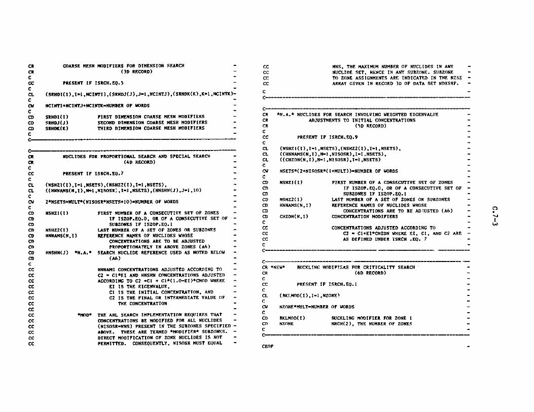
COARSE MESH MODIFIERS FOR DIMENSION SEARCH -(3D RECORD) -
PRESENT IF ISRCH.EQ.5 -
(SRHDI(I),I1m,NCINTI),(SRHDJ(J),J-1,NCINTJ),(SRHDK(K),K-1,NCINTK)-
NCINTI+NCINTJ+NCINTK-NUMBER OF WORDS -
SRHDI(I) FIRST DIMENSION COARSE MESH MODIFIERS -
SRHDJ(J) SECOND DIMENSION COARSE MESH MODIFIERS -
SRHDK(K) THIRD DIMENSION COARSE MESH MODIFIERS -
CCCCCCCC
NNS, THE MAXIMUM NUMBER OF NUCLIDES IN ANYNUCLIDE SET, HENCE IN ANY SUBZONE. SUBZONETO ZONE ASSIGNMENTS ARE INDICATED IN THE NZSZARRAY GIVEN IN RECORD 3D OF DATA SET NDXSRF.
C -
CRCRCCCCCLCCvCCDCDCD
NUCLIDES FOR PROPORTIONAL SEARCH AND SPECIAL SEARCH -(4D RECORD)
PRESENT IF ISRCH.EQ.7
(NSHZI(I),-1I,NSETS),(NSHZ2(I),I-1,NSETS), -((HNNAMS(N,I),Nm1,NISOSR ,I.1,NSETS),(HNSHN(J),J-1,1O)-
2*NSETS+NULT*(NISOSR*NSETS+10)-NUMRER OF WORDS -
NSHZl(I) FIRST NUMBER OF A CONSECUTIVE SET OF ZONES -
IF ISZOP.EQ.O, OR OF A CONSECUTIVE SET OFSUBZONES IF ISZOP.EQ.l
NSHZ2(I) LAST NUMBER OF A SET OF ZONES OR SUBZONES -HNNAMS(N,I) REFERENCE NAMES OF NUCLIDES WHOSE -
CONCENTRATIONS ARE TO BE ADJUSTED -PROPORTIONATELY IN ABOVE ZONES (A6) -
HNSHN(J) *N.A.* SEARCH NUCLIDE REFERENCE USED AS NOTED BELOW -
(A6) -
HNNAMS CONCENTRATIONS ADJUSTED ACCORDING TO -C2 - C1*EI AND HNSHN CONCENTRATIONS ADJUSTED -ACCORDING TO C2 -C1 + C1*(1.O-EI)*CMOD WHERE -
El IS THE EIGENVALUE, -
Cl IS THE INITIAL CONCENTRATION, AND -C2 IS THE FINAL OR INTERMEDIATE VALUE OF -
THE CONCENTRATION -
*MOD* THE ANL SEARCH IMPLEMENTATION REQUIRES THAT -CONCENTRATIONS BE MODIFIED FOR ALL NUCLIDES -
(NISOSR-NNS) PRESENT IN THE SUBZONES SPECIFIED -ABOVE. THESE ARE TERMED *MODIFIER* SUBZONES. -
DIRECT MODIFICATION OF ZONE NUCLIDES IS NOT -
PERMITTED. CONSEQUENTLY, NISOSR MUST EQUAL -
*N.A.* NUCLIDES FOR SEARCH INVOLVING WEIGHTED EIGENVALUEADJUSTMENTS TO INITIAL CONCENTRATIONS
(SD RECORD)
PRESENT IF ISRCH.EQ.9
(NSHZ1(I),I-1,NSETS),(NSHZ2(I),I-1,NSETS),((NNM(NINlIOS)I- NSES,
((CHZDN(NI+),N-I1,NISOSR),I1 SETST)
NSETS*(2+NISOSR*( I+MULT) )-NUMBER OF WORDS
NSHZI(I)
NSHZ2(I)HNNAMS(N,I)
CHZDN(N, I)
FIRST NUMBER OF A CONSECUTIVE SET OF ZONESIF ISZOP.EQ.O, OR OF A CONSECUTIVE SET OFSUBZONES IF ISZOP.EQ.l
LAST NUMBER OF A SET OF ZONES OR SUBZONESREFERENCE NAMES OF NUCLIDES WHOSE
CONCENTRATIONS ARE TO BE ADJUSTED (A6)CONCENTRATION MODIFIERS
CONCENTRATIONS ADJUSTED ACCORDING TOC2 - Cl+EI*CHZDN WHERE EI, Cl, AND C2 ARE
AS DEFINED UNDER ISRCH .EQ. 7
C--- --- _______ M-w
CR *NEW* BUCKLING MODIFIERS FOR CRITICALITY SEARCH'-CR (6D RECORD) -C -CC PRESENT IF ISRCH.EQ.1 -CCL (BKI.MOD(I),I1 ,NZONE) -C-CW NZONE*MULT-NUMBER OF WORDS -C-CD BKLMOD(I) BUCKLING MODIFIER FOR ZONE ICD ZONE NRCH(2), THE NUMBER OF ZONES -C-
CRCRCCCCCLCLC
CDCDCDCDCDCDCDCDCDCDCCCCCCCCCCCCCCCCCCCCCCCCCCCCCC
CRCRCRCCCCCLCLCLCCDCCDCCDCDCDCDCDCDCCCCCCCC
C
CEOF
-
-

C.R ATFLUX
REVISED 11/30/76CCCFCEC
ATFLUX-IVADJOINT TOTAL FLUXES
CD ORDER OF GROUPS IS ACCORDING TO INCREASINGCD ENERGY. NOTE THAT DOUBLE PRECISIONCD FLUXES ARE GIVEN WHEN MULT.EQ.2C
CR FILE IDENTIFICATION -C -CL HNAME,(HUSE(I),I-1,2),IVERS -CCW 1+3*MULT-NUMBER OF WORDS -C -CD NAME HOLLERITH FILE NAME - ATFLUX - (A6) -CD HUSE(I) HOLLERITH USER IDENTIFICATION (A6) -CD IVERS FILE VERSION NUMBER -CD MULT DOUBLE PRECISION PARAMETER -CD 1- A6 WORD IS SINGLE WORD -CD 2- A6 WORD IS DOUBLE PRECISION WORD -C -CCCR SPECIFICATIONS (ID RECORD) -C -CL NDIM,NGROUP,NINTI,NINTJ,NINTK,ITER,EFFK,ADUM,NBLOK -C -CW 9 -NUMBER OF WORDS -C -CD NDIM NUMBER OF DIMENSIONS -CD NGROJP NUMBER OF ENERGY GROUPS -CD NINTI NUMBER OF FIRST DIMENSION FINE MESH INTERVALS -CD NINTJ NUMBER OF SECOND DIMENSION FINE MESH INTERVALS -CD NINTK NUMBER OF THIRD DIMENSION FINE MESH INTERVALS. -CD NINTK.EO.1 IF NDIM.LE.2 -CD ITER OUTER ITERATION NUMBER AT WHICH FLUX WAS -CD WRITTEN -CD EFFK EFFECTIVE MULTIPLICATION FACTOR -CD ADUM RESERVED -CD NBLOK DATA BLOCKING FACTOR -CD IF NDIM.EO.1 THE GROUP VARIABLE IS BLOCKED -CD INTO NBLOK BLOCKS (SEE 2D RECORD BELOW) -CD IF NDIM.GE.2 THE 2ND DIMENSION VARIABLE IS -CD BLOCKED INTO NBLOK BLOCKS (SEE 3D RECORD)-C -C -- - - _ _- _ _ w M - - - -- -
C-CR ONE DIMENSIONAL ADJOINT TOTAL FLUX (2D RECORD) -C
CCCCLCCWC
PRESENT IF NDIM.EQ.I
((FADJ(I,J),I-1 ,NINTI),J-JL,.IU)--SEE STRUCTURE BELOW-----
NINTI*(JU - JL + 1)*MULT - NUMBER OF WORDS
C DO 1 M-1,NBLOKC I READ(N) *LIST AS AROVE*
CCCCCCCDC1)CC
WITH M AS THE BLOCK INDEX, JL=(M-1)*((NGROUP-1)/NBLOK+1)+1 -AND JU=MINO(NGROUP,JUP) WHERE JUPiM*((NGROUP-1)/NBLOK+1) -
FADJ(I,J) ONE DIMENSIONAL ADJOINT TOTAL FLUX BY INTERVAL -AND GROUP. -
C-C- M -. - M M _ r _ i w M
CRCCCCCLCCWCCCCCCCCCCCCDCDCC--CEO F
MULTI-DIMENSIONAL ADJOINT TOTAL FLUX (3D RECORD)
PRESENT IF NDIM.GE.2
((FADJ(I,J), I-1 ,NINTI)JJL,JU)-----SEE STRUCTURE BELOW----
NINTI*(JU - JL + 1)*MULT - NUMBER OF WORDS
DO 1 L- GROUPPDO I K-1,NINTKDO I -1,NBLOK
I READ(N) *LIST AS ABOVE*
- 0
- I- I-
WITH M AS THE BLOCK INDEX, JL=(M-1)*((NINTJ-1)/NBLOK +1)+lAND JL'-iIN(NINTJ,JUP) WHERE JUP=M*((NINTJ-1)/NBLOK +1)
FADJ(I,J) MULTI-DIMENSIONAL ADJOINT TOTAL FLUXBY INTERVAL AND GROUP.
CR** ***** *** *sfaataftatf s fffftff# *ffatfafs fffaf* * lf**
M M M IMM M M Mrs ir YM M
I

C.9 RZFLUX
-***********************************************************************
C REVISED 11/30/76CCF R7.FLUX-IV -C-CE REGULAR ZONE FLUX BY GROUP, AVERAGED OVER EACH ZONE -C -
C-_____ ---------- w---------
CR FILE IDENTIFICATION -
CCL HNAME,(HUSE(I),I1n,2),IVERS -C -CW 1+3*MULT-NUMBER OF WORDS -C -CD HNAME HOLLERITH FILE NAME - RZFLUX - (A6) -CD HUSE(I) HOLLERITH USER IDENTIFICATION (A6) -CD IVERS FILE VERSION NUMBER -CD MULT DOUBLE PRECISION PARAMETER -CD 1- A6 WORD IS SINGLE WORD -
CD 2- A6 WORD IS DOUBLE PRECISION WORD -
CC
CI)CI)Cl)C
CRCCLCCwCCCCCCCCCCDCDC
NZONENGROUPNCY
NUMBER OF GEOMETRIC ZONESNUMBER OF NEUTRON ENERGY GROUPSREFERENCE COUNT (CYCLE NUMBER)
FLUX VALUES (2D RECORD)
((ZG F(K,J),K-1 ,NGROUP) ,J-JL,JU) - SEE STRUCTURE BELOW-----
NGROlP*(JU-JL+1) - NUMBER OF WORDS
DO 1 M-1,NRLOKREAD(N) *LIST AS ABOVE*
WITH M AS THE BLOCK INDEX, JL-(M-1)*((NZONE-1)/NRLOK +1)+1AND JU-MINO(NZONE,JUP) WHERE JUP-M*((NZONE-1)/NBLOK +1)
ZGF(K,J) REGULAR ZONE FLUX BY GROUP, AVERAGED OVER ZONENEUTRONS/SEC-CM**2
CEOF
n
"-
SPECIFICATIONS (iD RECORD) -
TIME,POWER,VOL,EFFK,EIVS,DKDS,TNL,TNA,TNSL,TNBL,TNBAL,TNCRA, -l(X(I),I-1,3),NBLOK,ITPS,NZONE,NGROUP,NC? -
20-NUMBER OF WORDS
TIME REFERENCE REAL TIME, DAYS -POWER POWER LEVEL FOR ACTUAL NEUTRONICS PROBLEM,WATTS-
THERMALVOL VOLUME OVER WHICH POWER WAS DETERMINED, CC -EFFK MULTIPLICATION FACTOR -EIVS EICENVALUE OF SEARCH OF SEARCH PROBLEM -DKDS DERIVATIVE OF SEARCH PROBLEM -TNL TOTAL NEUTRON LOSSES -TNA TOTAL NEUTRON ABSORPTIONS -TNSL TOTAL NEUTRON SURFACE LEAKAGETNIL TOTAL NEUTRON BUCKLING LOSS -TNBAL TOTAL NEUTRON BLACK ABSORBER LOSS -TNCRA TOTAL NEUTRON CONTROL ROD ABSORPTIONS -X(I),I-1,3 RESERVEDNBLOK DATA BLOCKING FACTOR. THE GEOMETRIC ZONE -
VARIABLE IS BLOCKED INTO NBLOK BLOCKS. -ITPS ITERATIVE PROCESS STATE -=0, NO ITERATIONS DONE
"1, CONVERGENCE SATISFIED --2, NOT CONVERGED, BUT CONVERGING --3, NOT CONVERGED, NOT CONVERGING -
CRCCLCLCCwCCDCDCDCDCDCDCDCDCDCDCDCDCDCDCDCDCDCDCDCDCD
C - _ M - - - - - l - - -- Mr - M M N - - - - -

CCCCCCCDC
C.10 PWDINT
C*******,*********************************neseaeseseeesamnw*************
C REVISED 11/30/76CCF PWDINT-IV-C -CF. POWER DENSITY BY INTERVAL -CC*********************************************eeeeeee*****************
CCR FILE IDENTIFICATION-
C -
CL HNAME,(HUISE(I),I-1,2),IVERSC -CW 1+3*MULT-NUMBER OF WORDSC ~CD NAME HOLLERITH FILE NAME - PWDINT - (A6) -
CD HUSE(I) HOLLERITH USER IDENTIFICATION (A6) -CD IVERS FILE VERSION NUMBER
CD MULT DOUBLE PRECISION PARAMETERCD 1- A6 WORD IS SINGLE WORD
CD 2- A6 WORD IS DOUBLE PRECISION WORD -CCCCR SPECIFICATIONS (ID RECORD)CCI. TIME, POWER, VOL, NINTI,NINTJ,NINTK,NCYNBLOK -
CCW 8-NUMBER OF WORDSC -CD TIME REFERENCE REAL TIME, DAYSC) POWER POWER LEVEL FOR ACTUAL NEIITRONICS PROBLEM, -CD WATTS THERMALCD VOL VOLUME OVER WHICH POWER WAS DETERMINED,CC -CD NINTI NUMBER OF FIRST DIMENSION FINE INTERVALS -CD NINT.1 NUMBER OF SECOND DIMENSION FINE [NTERVALS -CD NINTK NUMBER OF THIRD DIMENSION FINE INTERVALS -
CD NCY REFERENCE COUNT (CYCLE NUMBER)
Cl) NBLOK DATA BLOCKING FACTOR. THE SECOND DIMENSION -
CD VARIABLE IS BLOCKED INTO NBLOK BLOCKS. -
CC
CRCCLCCWCCSCSCS
POWER DENSITY VALUES (2D RECORD)
((PWR(I,J), 1-1,NINTI)J-JL,JU)---SEE STRUCTURE BELOW-----
NINTI*(JU - JL + 1) - NUMBER OF WORDS
DO 1 K-1,KMDO 1 M-1 , NBLOK
I RFAD(N) *LIST AS ABOVE*
C-
WITH M AS THE BLOCK INDEX, JL-(M-1)*((NINTJ-1)/NBLOK +1)+1 -
AND JU-MINO(NINTJ,JUP) WHERE JIUP-M*((NINTJ-1)/NBLOK +1) -
PWR(I,J) POWER DENSITY BY INTERVAL, WATTS/CC -
CEOF
n
0
w w w f w r f M M M
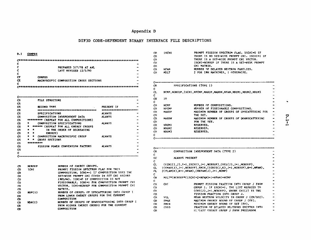
Appendix D
DIF3D CODE-DEPENDENT BINARY INTERFACE FILE DESCRIPTIONS
D.1 COMPXS
CPREPARED 3/7/78 AT ANLLAST REVISED 12/5/80
CF COMPXS -CE MACROSCOPIC COMPOSITION CROSS SECTIONS -C -
C
FILE STRUCTURE
RECORD TYPE
SPECI FICATIONSCOMPOSITION INDEPENDENT DATA
***** (REPEAT FOR ALL COMPOSITIONS)* COMPOSITION SPECIFICATIONS* *** (REPEAT FOR ALL ENERGY GROUPS* * IN THE ORDER OF DECREASING* * ENERGY)* * COMPOSITION MACROSCOPIC GROUP* * CROSS SECTIONS
F OR******
FISSION POWER CONVERSION FACTORS
NCROUIPICHI
NUP(I)
NDN(I)
PRESENT IF -
ALWA -WA
ALWAYS -
ALWAYS -
ALWAYS -
CDCDCDCDCDCDCD
ISCHI
NFAMMULT
PROMPT FISSION SPECTRUM FLAG. ISCHI-O IFTHERE IS NO SET-WIDE PROMPT CHI. ISCHI-1 IFTHERE IS A SET-WIDE PROMPT CHI VECTOR.ISCHI-NGROUP IF THERE IS A SET-WIDE PROMPTCHI MATRIX.NUMBER IF DELAYED NEUTRON FAMILIES.2 FOR IBM MACHINES, 1 OTHERWISE.
CR SPECIFICATIONS (TYPE 1) -C -CL NCMP,NGROUP,ISCHI ,NFCMP,MAXUP,MAXDN,NFAM,NDUM1 ,NDUM2,NDUM3 -CCV 10-C-CD NCMP NUMBER OF COMPOSITIONS. -CD NFCMP NUMBER OF FISSIONABLE COMPOSITIONS. -CD MAXUP MAXIMUM NUMBER OF GROUPS OF UPSCATTERING FOR -CD THE SET.-CD MAXDN MAXIMUM NUMBER OF GROUPS OF DOINSCATTERING -CD FOR THE SET. -CD NDUM1 RESERVED. -CD NDUM2 RESERVED.CD) NDUM3 RESERVED.-C-C-- - -- --- M M-M-M-__-__-M---- --
-
ALWAYS
NITMBER OF ENERGY GROUPS.PROMPT FISSION SPECTRUM FLAG FOR THISCOMPOSITION. ICHIw-1 17 COMPOSITION USES THESET-WIDE PROMPT CHI GIVEN IN SET CHI RECORD(BELOW). ICHI-O IF COMPOSITION IS NOTFISSIONABLE. ICHI-1 FOR COMPOSITION PROMPT CHIVECTOR. ICHI-NGROUP FOR COMPOSITION PROMPT CHIMATRIX.NUMBER OF GROUPS OF UPSCATTERING INTO GROUP I
FROM LOWER ENERGY GROUPS FOR THE CURRENTCOMPOSITIONNUMBER OF GROUPS OF DOWNSCATTERING INTO GROUP I
FROM HIGHER ENERGY GROUPS FOR THE CURRENT
COMPOSITION
CRCCCCCI.CLCLCCWCCDCDCDCDCI)CDCI)CDCD
COMPOSITION INDEPENDENT DATA (TYPE 2)
ALWAYS PRESENT
((CHI(IJ),I-1,ISCHI),J-1,NGROUP),(VEL(J),J-1,NGR1JP),1(EMAX(J),J-1,NGROIIP),EMIN,((CHID(JK),J-1,NGROUIP),K-1,NFAH),2(FLAM(K),K-1,NFAM),(NKFAM(J),J-1 ,NCMP)
MULT*(NGROUIP*(ISCHI+2+NFAM)+1+NFAM)+NCMP
CHI
VELEMAXEM ICliID
PROMPT FISSION FRACTION INTO GROUP J FROMGROUP I. IF ISCHI-I, THE LIST REDUCES TO(CHI(J),J-1,NGROIJP), WHERE CHI(J) IS THEFISSION FRACTION INTO GROUP J.MEAN NEUTRON VELOCITY IN GROUP J (CM/SEC).MAXIMUM ENERGY BOUND OF GROUP J (EV).MINIMUM ENERGY BOUND OF SET (EV).FRACTION OF DELAYED NEUTRONS EMITTED INTONWTIRON ENERGY GROUP J FROM PRECURSOR
CC
CSCSCSCSCSCSCSCSCSCSCSCSCSCSCSCSCC
CDCDCDCI)Cl)CDCDCDCDCDCDCDCDCD

FLAME
NKFAM
FAMILY K.DELAYED NEUTRON PRECURSOR DECAY CONSTANTFOR FAMILY K.NUMBER OF FAMILIES TO WHICH FISSION INCOMPOSITION J CONTRIBUTES DELAYED NEUTRONPRECURSORS.
C-
CCR COMPOSITION SPECIFICATIONS (TYPE 3)
C -CC ALWAYS PRESENT -C -CL ICKI,(NUP(I),Ii1,NGROUP),(NDN(I),I1,NGROUP), -CL l(NUMFAM(I),1.1,NKFAMI) -C -CC NKFAMI " NKFAM(K) -C -CW 1+2NCROUP+NKFAMI -C -CD NUMFAM FAMILY NUMBER OF THE I-TH YIELD VECTOR IN -
CD ARRAY SNUDEL(I)., -C -C__
CDCDCDCDCDCDC
COMPOSITION MACROSCOPIC GROUP CROSS SECTIONS (TYPE 4)
ALWAYS PRESENT
XAXTOTXRF.MXTR,XFXNF,(CHI(I),I.1,ICHI),1(XSCATU(Ii,11,NUMUP),XSCATJ,(XSCATD(I),I.1,NUMDN),2PC,AI,B1,A2,B2,A3,B3,(SNUDEL(I),Ii1,NKFAMI),XN2N
NUMUP NUP FOR THE CURRENT GROUPNUNDN " NDN FOR THE CURRENT GROUPNKFAMI " NKFAM(K)
MILT(5I S+ICHI +NUMUP+NUMDN+NK FAHI) IF ICHI..GT.OMIULT*(15+NUMUP+NUMDN+NKFAMI) IF ICHI.EQ.-lMULT*(13+NUMUP+NUMDN+NKFAMI) IF ICHI.EO.O
XA ABSORPTION CROSS SECTION.XTOT TOTAL CROSS SECTION.XREM REMOVAL CROSS SECTION, TOTAL CROSS SECTION
FOR REMOVING A NEUTRON FROM GROUP J DUE TO ALL.PROCESSES.
XTR TRANSPORT CROSS SECTION.XF FISSION CROSS SECTION, PRESENT ONLY IF
ICHI-NE.O.KNF TOTAL NUMBER OF NEUTRONS EMITTED PER FISSION
CR
CCCCCLCCWC
CDCr)CDCDCDCDCDCDCDCr)CDCDCDCDCDCDCDCDCDCDCDCI)CDCDCr)CDCDCDCT)CDCDCDCI)Cr)Cl)CCNCNCNCNCNC
CHI
XSCATU
XSCATJ
XSCATD
PC
Al
BI
A2
B2
A3
B3
SNUDEL
XN2N
FISSION POWER CONVERSION FACTORS (TYPE 5)
ALWAYS PRESENT
(FPWS(I),I-l ,NCMP)
MILT*NCMP
TIMES XF, PRESENT ONLY IF ICHI.NE.O. -PROMPT FISSION FRACTION INTO GROUP J FROM -GROUP I, PRESENT ONLY IF ICHI.GT.O. IF ICHI-1, -THE LIST REDUCES TO THE SINGLE NUMBER CHI, -WHICH IS THE PROMPT FISSION FRACTION INTO -GROUP J. -TOTAL SCATTERING CROSS SECTION INTO GROUP J -FROM GROUPS J+NUP(J),J+NUP(J)-I,...,J+2,J+I, -PRESENT ONLY IF NUP(J).GT.O. -TOTAL SELF-SCATTERING CROSS SECTION FROM -GROUP J TO GROUP J. -TOTAL SCATTERING CROSS SECTION INTO GROUP J -FROM GROUPS J-1,J-2,... ,J-NDN(J), PRESENT -ONLY IF NDN(J).GT.O. -PC TIMES THE GROUP J REGION INTEGRATED -FLUX FOR THE REGIONS CONTAINING THE CURRENT -COMPOSITION YIELDS THE POWER IN WATTS IN THOSE -REGIONS AND ENERGY GROUP J DUE TO FISSIONS -AND NON-FISSION ARSORPTIONS. -FIRST DIMENSION DIRECTIONAL DIFFUSION -COEFFICIENT MULTIPLIER. -FIRST DIMENSION DIRECTIONAL DIFFUSION -COEFFICIENT ADDITIVE TERM. -SECOND DIMENSION DIRECTIONAL DIFFUSION -COEFFICIENT MULTIPLIER. -SECOND DIMENSION DIRECTIONAL DIFFUSION -COEFFICIENT ADDITIVE TERM. -THIRD DIMENSION DIRECTIONAL DIFFUSION -COEFFICIENT MULTIPLIER. -THIRD DIMENSION DIRECTIONAL DIFFUSION -COEFFICIENT ADDITIVE TERM. -NUMBER OF DELAYED NEUTRON PRECURSORS PRODUCED -IN FAMILY NUMBER NUMFAM(I) PER FISSION -IN GROUP J. -N,2N REACTION CROSS SECTION -
THE MACROSCOPIC XN2N(J) TIMES THE FLUX IN GROUP-J GIVES THE RATE AT WHICH N,2N REACTIONS OCCUR -IN GROUP J. THUS, FOR N,2N SCATTERING, -XN2N(J)-O.5*(SUM OF SCAT(J TO G)) SUMMED OVER -ALL G WHERE SCAT IS THE N,2N SCATTERING MATRIX.-
CRCCCCCLCLCLCCCCCC
CCWCWCWCCDCDCT)CI)CDCDCDCDCD
Id"
1"r
C

CD FPWSC
FISSIONS/WATT-SECOND FOR EACH COMPOSITION
C
CEOF
D.2 DIF3D
C REVISED 5/26/83 -C -CF DIF3D -CE ONE-, TWO-, AND THREE-DIMENSIONAL DIFFUSION THEORY -CE NODULE DEPENDENT BINARY INPUT -C -
C***************************************..******.....********.
CCR FILE IDENTIFICATION -C -CL HNAME,(HUSF(I),I-I,2),IVERSC -CW 1+3*MULT"NUMBER OF WORDS -CCD NAME HOLLERITH FILE NAME DIF3D - (A6) -CD HUSE(I) HOLLERITH USER IDENTIFICATION (A6) -CD IVERS FILE VERSION NUMBER -CD MELT DOUBLE PRECISION PARAMETER -Cl) I- A6 WORD IS SINGLE WORD -CI) 2- A6 WORD IS DOUBLE PRECISION WORD -
C -
C M -
CC------------------------- --------------------
C--------CRCCLCLCLCLCCWCCDCDCDCDCDCDCDCDCDCDCDCDCDCDCDCDCDCDCD
CDCDCDCDCDCDCDCDCDCDCD
CDCDCDCDCDCI)CDCDCD
CD
PROBLEM TITLE, STORAGE AND DUMP SPECIFICATIONS (1D RECORD)
(TITLE(I),-I1,11),MAXSIZMAXBLK,IPRINT
3+11*MULTNUMBER OF WORDS
TITLE ANY ALPHANUMERIC CHARACTERSMAXSIZ POINTR CONTAINER ARRAY SIZE IN FAST CORE
MEMORY (FCM) IN REAL*R WORDSMAXBLK POINTR CONTAINER ARRAY SIZE IN EXTENDED CORE
MEMORY (ECM) IN RF.AL*R WORDSIPRINT POINTER DEBUGGING EDIT
0...NO DEBUGGINC PRINTOUT1...DEBUGGING DUMP PRINTOUT
2...DEBUGGING TRACE PRINTOUT3...BOTH DUMP AND TRACE PRINTOUT
PROBLEM INTEGER CONTROL PARAMETERS (2D RECORD)
IPROBT, ISOLNT, IXTRAP,MINBSZ,NOtITMX, IRSTRT,LIMTIM,NUPMAX, IOSAVE,IIOMEGINRMAX,NUMORP,IRETRN,(IF.DF(I),.-1,1IO),NOUTBQ,IOFLUX,2NOEDIT, NOD3ED, I SRHED, NSN, NSWMAX , IAPRX, IAPRXZ, NCMI , ISEXTR , NZSWP,INCMR7.S,(IDUM(I),I-.1,9)
45-NUMBER OF WORDS
IPROBT
ISOLNT
IXTRAP
MINBSZ
NOUTMX
IRSTRT
LIMTIM
NJUPMAX
IOSAVE
IOMPG
INRMAX
PROBLEM TYPE0...K-EFFECTIVE PROBLEM1...FIXED SOURCE PROBLEMSOLUTION TYPE0...REAL SOLUTION1...ADJOINT SOLUTION2...BOTH REAL AND ADJOINT SOLUTIONCHEBYSHEV ACCELERATION OF OUTER ITERATIONS0...YES, ACCELERATE THE !'LITER ITERATIONS1...NO ACCELERATIONMINIMUM PLANE-BLOCK (RECORD) SIZE IN REAL*8WORDS FOR I/O TRANSFERS IN THE CONCURRENTITERATION STRATEGYOUTER ITERATION CONTROL-3...BYPASS DIF3D MODULE.-2...PERFORM NEUTRONICS EDITS ONLY-1...PERFORM NEUTRONICS EDITS AND CALCULATE
OPTIMUM OVERRELAXATION FACTORS ONLY.CE.O...MAXIMUM NUMBER OF OUTER ITERATIONS
RESTART FLAG0...THIS IS NOT A RESTART1...THIS IS A RESTART.JOB TIME LIMIT, MAXIMUM (CP AND PP (OR WAIT))PROCESSOR SECONDSNUMBER OF [IPSCATTER ITERATIONSPER OUTER ITERATIONCONCURRENT ITERATION EFFICIENCY OPTION0...PERFORM THE ESTIMATED NO. OF INNER
ITERATIONS FOR EACH GROUP1...AVOID THE LAST PASS OF INNER ITERATIONS
IN THOSE GROUPS FOR WHICH THE NUMBER OFINNER ITERATIONS IN THE LAST PASS ARE LESSTHAN A CODE DEPENDENT THRESHOLD
OPTIMUM OVERRELAXATION FACTOR ESTIMATIONACCELERATION OPTION.... NO ACCELERATION.1...ASYMPTOTIC EXTRAPOLATION OF ITERATIONS IN
THE OPTIMUM OVERRELAXATION FACTORCALCULATION.
MAXIMUM NUMBER OF ITERATIONS PERMITTED DURING
"~N-
CRCCLCCCCDCDCDCDCDCDCDCDCDCD

CDCDCDCDCDCDCDCDCT)CDCDCDCDCDCDCDCDCDCDCDCDCDCDCDCDCDCDCDCDCDCDCDCDCDCDCDCDCDCDCDCDCDCDCDCDCDCDCDCDCDCDCDCDCD
NUMORPIRETRN
IEDF( 1)
IEDF(2)
IEDF(3)
IEDF(4)
IEDF(5)
THE OPTIMUM OVERRELAXATION FACTOR ESTIMATION -PROCESS FOR EACH INNER (WITHIN GROUP) -ITERATION MATRIX. -NUMBER OF OPTIMUM OVERRELAXATION FACTORS -FLAG INDICATING CAUSE OF OUTER ITERATION -TERMINATION -0...INITIAL VALUE, PRIOR TO OUTER ITERATIONS -I...OUTER ITERATIONS CONVERGED -2...MAXIMUM NUMBER OF OUTER ITERATIONS -
PERFORMED -3...TIME LIMIT -
PROBLEM DESCRIPTION EDIT (IN ADDITION TO USER -INPUT SPECIFICATIONS WHICH ARE ALWAYS EDITED -0...NO EDITS -R...PRINT EDITS2...WRITE EDITS TO AUXILIARY OUTPUT FILE -3...VRITE EDITS TO BOTH PRINT AND AUXILIARY -
OUTPUT FILE -GEOMETRY (REGION TO MESH INTERVAL) MAP EDIT0...NO EDITS -I...PRINT EDITS -2...VRITE EDITS TO AUXILIARY OUTPUT FILE3...VRITE EDITS TO BOTH PRINT AND AUXILIARY -
OUTPUT FILE -GEOMETRY (ZONE TO MESH INTERVAL) MAP EDIT0...NO EDITS -1...PRINT EDITS -2...WRITE EDITS TO AUXILIARY OUTPUT FILE -3...WRITE EDITS TO BOTH PRINT AND AUXILIARY -
OUTPUT FILE -MACROSCOPIC CROSS SECTION EDIT -ENTER TWO DIGIT NUMBER SP WHERE -
S CONTROLS THE SCATTERING CROSS SECTIONS EDIT -P CONTROLS THE PRINCIPAL CROSS SECTIONS EDIT -
THE INTEGERS S AND P SHOULD BE ASSIGNED ONE OF -THE FOLLOWING VALUES (LEADING ZEROES ARE -IRRELEVANT) -0...NO EDITS -I...PRINT EDITS -2...WRITE EDITS TO AUXILIARY OUTPUT FILE -3...WRITE EDITS TO BOTH PRINT AND AUXILIARY -
OUTPUT FILEBALANCE EDITS -ENTER 3 DIGIT NUMBER GBR WHERE -
G CONTROLS GROUP BALANCE EDITS INTEGRATED OVER -THE REACTOR -
B CONTROLS REGION BALANCE EDIT BY GROUP -R CONTROLS REGION BALANCE EDIT TOTALS -(INCLUDING NET PRODUCTION AND ENERGY MEDIANS)-
THE INTEGERS G, B, AND R SHOULD BE ASSIGNED -
CDCDCDCDCDCDCDCDCT)CDCI)CDCDCDCDCDCDCDCT)CDCDCDCDCDCDCDCDCDCDCDCT)CDCD
CDCDCDCDCDCD
CDCDCDCDCDCDCDCT)CD)CDCDCDCDCDCD
IEDF(6)
IEDF(7)
IFDF(R)
IEDF(9)
IEDF( 10)
ONE OF THE FOLLOWING VALUES (LEADING ZEROES -
ARE I RRF.LEVANT)0...NO EDITSI...PRINT EDITS2...WRITE EDITS TO AUXILIARY OUTPUT FILE -
3...WRITE EDITS TO BOTH PRINT AND AUXILIARY -
OUTPUT FILESPOWER EDITSENTER 2 DIGIT NUMBER RN WHERE
R CONTROLS REGION POWER AND AVERAGE POWER
EDITSM CONTROLS POWER DENSITY BY MESH INTERVAL -
EDIT (PWDINT)
THE INTEGERS R AND M SHOULD BE ASSIGNED ONE OF -
THE FOLLOWING VALUES (LEADING ZEROES ARE -
IRRELEVANT)0...NO EDITSI...PRINT EDITS
2...WRITE EDITS TO AUXILIARY OUTPUT FILE -
3...WRITE EDITS TO BOTH PRINT AND AUXILIARY -
OUTPUT FILETOTAL FLUX EDITSENTER 3 DIGIT INTEGER RMB WHERE
R CONTROLS TOTAL FLUX EDIT BY REGION AND GROUP -INCLUDING GROUP AND REGION TOTALS
M CONTROLS TOTAL FLUX EDIT BY MESH INTERVAL -INTEGRATED OVER GROUP
B CONTROLS TOTAL FLUX EDIT BY MESH INTERVAL -
AND GROUP (RTFLUX OR ATFLUX) -
THE INTEGERS R, M, AND B SHOULD BE ASSIGNED -
ONE OF THE FOLLOWING VALUES (LEADING ZEROES -
ARE IRRELEVANT)0...NO EDITSI...PRINT EDITS
2...WRITE EDITS TO AUXILIARY OUTPUT FILE -
3...WRITE EDITS TO BOTH PRINT AND AUXILIARYOUTPUT FILE
ZONE AVERAGED FLUX EDIT0...NO EDITS1...PRINT EDITS2...WRITE EDITS TO AUXILIARY OUTPUT FILE -
3...WRITE EDITS TO BOTH PRINT AND AUXILIARY -OUTPUT FILE
REGION AVERAGED FLUX EDIT -0...NO EDITSI...PRINT EDITS2...WRITE EDITS TO AUXILIARY OUTPUT FILE -
3...WRITE EDITS TO BOTH PRINT AND AUXILIARY -
OUTPUT FILESTANDARD INTERFACE FILES TO BE WRITTEN IN -
d
"
N
I
N
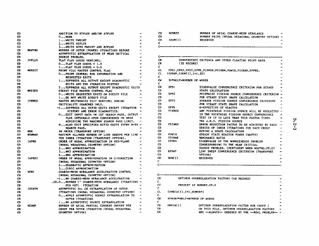
CDCDCDC
CDCDCDCDCDCDCDCDCDCDCDCDCDCDCDCDCDCDCDCDCDCDCDCDCDCDCDCDCDCDCDCDCDCDCDCDCDCDCDCDCDCDCDCDCDCDCDCDCDCD
CDCDCD
C--
C-
NOUTBO
IOFLUX
NOEDIT
W)D3ED
ISRHED
NSNNSWMAX
IAPRX
IAPRXZ7
NCMI
ISEXTR
NZSWP
ADDITION TO RTFLUX AND/OR ATFLUX -0...NONE -1...WRITE PWDINT -2...WRITE RZFLUX -3...WRITE BOTH PWDINT AND RZFLUX -NUMBER OF OUTER (POWER) ITERATIONS BEFORE -ASYMPTOTIC EXTRAPOLATION OF NEAR CRITICAL -SOURCE PROBLEM. -FLAT FLUX GUESS SENTINEL. -O...FLAT FLUX GUESS " 1.0 -1...FLAT FLUX GUESS " 0.0 -PRINT FILE MASTER CONTROL FLAG0...PRINT GENERAL RUN INFORMATION AND -
REQUESTED EDITS1...SUPPRESS ALL OUTPUT EXCEPT DIAGNOSTIC -
EDITS AND THE ITERATION HISTORY -2...SUPPRESS ALL OUTPUT EXCEPT DIAGNOSTIC EDITSD3EDIT FILE MASTER CONTROL FLAG -0...WRITE REQUESTED EDITS ON D3EDIT FILE -1...DO NOT WRITE D3EDIT FILEMASTER NEUTRONICS EDIT SENTINEL DURING -CRITICALITY SEARCHES ONLY.-1...SUPPRESS ALL DIF3D EDITS EXCEPT ITERATION -
HISTORY AND ERROR DIAGNOSTICS. -0...EDIT INPUT DATA ON 1ST SEARCH PASS, OUTPUT -
FLUX INTEGRALS UPON CONVERGENCE OR UPON -ACHIEVING THE MAXIMUM SEARCH PASS LIMIT. -
N...ALSO EDIT SPECIFIED DIF3D EDITS EVERY N-TH -SEARCH PASS. -
SN ORDER (TRANSPORT OPTION)MAXIMUM ALLOWED NUMBER OF LINE SWEEPS PER LINE -PER INNER ITERATION (TRANSPORT OPTION). -ORDER OF NODAL APPROXIMATION IN HEX-PLANE -(NODAL HEXAGONAL GEOMETRY OPTION) -2...NH2 APPROXIMATION -3...NH3 APPROXIMATION -4...NH4 APPROXIMATION -ORDER OF NODAL APPROXIMATION IN Z-DIRECTION -(NODAL HEXAGONAL GEOMETRY OPTION) -2.. .QUADRATIC APPROXIMATION3...CUBIC APPROXIMATION -
COARSE-MESH REBALANCE ACCELERATION CONTROL -(NODAL HEXAGONAL GEOMETRY OPTION) -
-1...NO COARSE-MESH REBALANCE ACCELERATION -.GE.O...NUMBER C' COARSE-MESH REBALANCE ITERATIONS -
PER OUTS ITERATION -ASYMPTOTIC SOL.CE EXTRAPOLATION OF OUTER -ITERATIONS (NODAL HEXAGONAL GEOMETRY OPTION) -0...APPLY ASYMPTOTIC SOURCE EXTRAPOLATION TO -
OUTER ITERATIONS -1...NO ASYMPTOTIC SOURCE EXTRAPOLATION -NUMBER OF AXIAL PARTIAL CURRENT SWEEPS PER -GROUP PER OUTER ITERATION (NODAL HEXAGONAL -GEOMETRY OPTION) -
NCMR7.S
IDUM(I)
NUMBER OF AXIAL COARSE-MESH REBALANCE -NUMBER PAIRS (NODAL HEXAGONAL GEOMETRY OPTION) -RESERVED -
CONVERGENCE CRITERIA AND OTHER FLOATING POINT DATA(3D RECORD)
EPSI,EPS2,EPS3,EFFK,FISMINPSINRM,POWIN,SICBAR,EFFKQ,IEPSWP,(DUM(I),I-1,20)
30*MULT=NUMBER OF WORDS
CRCRCCLCLCCWCCDCDCDCDCDCDCDCDCDCDCDCD
CDCD
CDCDCDCDCDCDCDCDC
EIGENVALUE CONVERGENCE CRITERION FOR STEADY -STATE CALCULATION -POINTWISE FISSION SOURCE CONVERGENCE CRITERION -FOR STEADY STATE SHAPE CALCULATION -AVERAGE FISSION SOURCE CONVERGENCE CRITERION -FOR STEADY STATE SHAPE CALCULATION -K-EFFECTIVE OF REACTOR -ANY POINTWISE FISSION SOURCE WILL BE NEGLECTED -IN THE POINTWISE FISSION SOURCE CONVERGENCE -TEST IF IT IS LESS THAN THIS FACTOR TIMES -THE A.M.S. FISSION SOURCE -ERROR REDUCTION FACTOR TO BE ACHIEVED BY EACH -SERIES OF INNER ITERATIONS FOR EACH GROUP -DURING A SHAPE CALCULATION -STEADY STATE REACTOR POWER (WATTS) -DOMINANCE RATIO -EIGENVALUE OF THE HOMOGENEOUS PROBLEM -CORRESPONDING TO THE NEAR CRITICAL -SOURCE PROBLEM. (PERTINENT WHEN NOUTBQ.GT.O) -LINE SWEEP CONVERGENCE CRITERION (TRANSPORT -OPTION) -RESERVED -
OPTIMUM OVERRELAXATION FACTORS (4D RECORD)
PRESENT IF NUMORP.GT.O
(OMF.GA(I),I-1.NUMORP)
NUMORP*MUL.T-NlTMBER OF WORDS
OMEGA(I) OPTIMUM OVERRELAXATION FACTOR FOR GROUP ION THIS FILE, OPTIMUM OVERRELAXATION FACTORSARE --ALWAYS-- ORDERED BY THE --REAL PROBLEM-
EPS1
EPS2
EPS3
EFFKFISMIN
PSINRM
POWINSIGRAREFFKO
EPSWP
DUM(I)
CRCCCCCLCCWCCI)Cl)CD
0
N
c -_ --Y --- -w - -
rYY

ORDERING
C
AXIAL COARSE-ME!H REBALANCE BOUNDARIES FOR NODAL
HEXAGONAL GEOMETRY OPTION (SD RECORD)
PRESENT IF NCMRZS.GT.O
(ZCMRC(I),I-1,NCMRZS),(NZINTS(I),I-1,NCMRZS)
NCMRZS*(MILT+1)-NUMBER OF WORDS
7.CMRC( I)
NZINTS( I)
UPPER Z-COORDINATE OF AXIAL COARSE-MESH -REBALANCE SPECIFICATION INTERVAL I.-NUMBER OF AXIAL COARSE MESH REBALANCE INTERVALS-IN I-TH SPECIFICATION INTERVAL.
THERE ARE NZINTS(I) AXIAL COARSE-MESH REBALANCE -
INTERVALS BETWEEN ZCMRC(I-1) AND ZCMRC(I), WHERE -WHERE ZCMRC(O) IS THE LOWER REACTOR BOUNDARY -IN THE Z-DIRECTION. THE ZCMRC(I) ARE ORDERED SUCH -
THAT ZCMRC(I+1).GT.ZCMRC(I). -
CDC
CEO F
D.3 LABELS
C***********************************************************************
C PREPARED 2/21/78 AT ANL -C LAST REVISED 12/12/83 -CCF LABELSC -CE REGION AND COMPOSITION LABELS, AREA DATA, -CF. HALF HEIGHTS, NUCLIDE SET LABELS, ALIAS ZONE LABELS, -
CE CONROL-ROD MODEL DATA -C-
FILE IDENTIFICATION
HNAME,(HUSE(I),I-1,2),IVERS
1+3*MULT-NUMBER OF WORDS
HNAMFHIJSE(I)IVERSMULT
HOLLERITH FILE NAME - LABELS - (A6)HOLLERITH USER IDENTIFICATION (A6)FILE VERSION NUMBERDOUBLE PRECISION PARAMETER
1 - A6 WORD IS SINGLE WORD2 - A6 WORD IS DOUBLE PRECISION WORD
CRCRCCCCCLCCV
CDCDCDCDCDCN
CN
CN
CH
C
M
M
CDCDCDCDCDCDCC-
C-CSCSCSCSCSCSCSCSCSCSCSCSCSCSCSCSCSCSCSCC-
C-CRCCLCLCLC
CDCDCDCDCDCDCDCDCD)
CDCDCD)
NHST2
DISTANCE SPECIFICATIONS0 - NONE1 - SINGLE VALUE USED EVERYWHERE.EQ.NREG - REGION DEPENDENT
NUMBER OF HALF-HEIGHT AND EXTRAPOLATIONDISTANCE SPECIFICATIONS FOR THE SECOND
FILE STRUCTURE
RECORD TYPE
FILE IDENTIFICATIONSPECI FICTIONS
LABEL AND AREA DATAFINITE-GEOMETRY TRANSVERSEDISTANCES
NUCLIDE SET LABELSALIAS ZONE LABELS
GENERAL CONTROL-ROD MODEL DATA
***********(REPEAT FOR ALL BANKS)* CONTROL-ROD BANK DATA*
* *******(REPEAT FOR ALL RODS IN BANK)* * CONTROL-ROD CHANNEL DATA
PRESENT IF
ALWAYS-ALWAYS -ALW; YS-NHTSI.GT.O OR -
NGTS2.GT.O -NSETS.CT. 1-NALIAS.CT.O -NBANKS.GT.O -
NBANKS.GT.O -
(LLCHN+LLROD+hIESH). GT.0-
CRCCLCCVC
M w M Mll w w f w ws r w M
MM M w Mw w w wM ww w
SPECIFICATIONS (1D RECORD)
tTZSZ,NREG,NAREA,LREGA,NHTS1,NHTS2,NSETS,NALIAS,NTRI,NRING, -NCHAN,NBANKS,LINTAX,MAXTIM,MAXROD,MAXMSH,MAXLRD,MAXLCH, -(IDUM(I),I-1,6) -
24-NIIKBER OF WORDS -
NTZSZ NUMBER OF ZONES AND SUBZONES -NRE.G NUMBER OF REGIONS-NARE.A NUMBER OF AREAS-LREGA LENGTH OF NRA ARRAY -NH1TS! NUMBER OF HALF-HEIGHT AND EXTRAPOLATION -
"
W
I
N

CDCDCDCDCDCDCDCDCDCDCDCDCDCDCDCDCDCDCDCDCDCDCDCDCCMC?'
CH
CH
C
LABEL AND AREA DATA (2D RECORD)
(OMPNAM(I),I-1,NTZSZ) ,(REGNAM(I),1-1 , NREC), -I(ARANAM(I),I-1 ,NAREA), -2(NRA(I),I-1,LREGA),
MLT*(NTZSZ+NREG+NAREA )+LREGA-NUMBER OF WORDS -
CMPNAM( I) ZONE OR SUBZONE LABEL. SUIZONES FOLLOW ZONES -REGNAM(I) REGION LABELARANAM(I) AREA LABEL -NRA(I) REGION/AREA ASSIGNMENTS. NRA(N(J)) IS THE -
NUMBER OF REGIONS IN AREA J. (NRA(I),I-N(J)+1, -N(J+1)-1) IS A LIST OF THE REGION NUMBERS FOR -THOSE REGIONS. N(1)-1. N(J+1)-N(J)+1+NRA(N(J)).-LREGA-SUM (1+NRA(N(J))) FOR J-1,NAREA -
DIRECTION.0 - NONENHTS1 - SAME AS NHTS1
NUMBER OF NUCLIDE SETS -0 IF RECORD SD IS NOT PRESENT. IF GREATER -THAN 0, RECORD 5D IS PRESENT AND THE ALIASARRAY IS OF LENGTH NALIAS.-NO. OF TRIANGLES PER HEX FOR TRIANGULAR -GOEMETRIES -MAX. NO. OF RINGS OF HEXAGONS FOR TRIANGULAR -GEOMETRIES -NO. OF CONTROL-ROD CHANNELS IN THE MODEL -NO. OF CONTROL-ROD BANKS -ORIGINAL NO. OF FINE MESH INTERVALS IN AXIAL -DIMENSION -MAXIMUM VALUE OF NTIMES(I) (I-i,NBANKS) -MAXIMUM VALUE OF NRODS(I) (I-I,NBANKS) -MAXIMUM VALUE OF NMESH(K) (K1 ,LRODS; -I-1,NRANKS) WHERE LRODS-NRODS(I) -MAXIMUM VALUE OF LENROD(K) (K-1,LRODS; -I1i.NBANKS) -MAXIMUM VALUE OF LENCHN(K) (K-l,LRODS; -I.1,NBANKS)RESERVED -
THE AXIAL DIMENSION IS Z IN RZ, XYZ, HEX-Z AND -TRIANGULAR-Z GEOMETRIES. IT IS Y IN XY GEOMETRY. -NCHAN IS THE SUM OF NRODS (RECORD 6D) OVER ALL CONTROL -ROD BANKS. -
FINITE-GEOMETRY TRANSVERSE DISTANCES (3D RECORD)
PRESENT IF NHTSI.GT.O OR NHTS2.GT.O
(HAFHT1(I),I-1 ,NHTS1),(XTRAP1(I),I-1,NHTS1),1(HAFHT2(I),I-1,NHTS2),(XTRAP2(I),I-1,NHTS2)
2*(NHTS1+NHTS2)-NUMBER OF WORDS
HAFHT1(I) ACTUAL TRANSVERSE HALF HEIGHT FOR REGION IXTRAPI(I) TRANSVERSE EXTRAPOLATION DISTANCE FOR
REGION IhAFHT2(I) ACTUAL TRANSVERSE HALF HEIGHT FOR REGION I
IN THE SECOND DIRECTIONXTRAP2(I) TRANSVERSE EXTRAPOLATION DISTANCE FOR
REGION I IN THE SECOND DIRECTION
IF HAFHTN(I)+XTRAPN(I)-O.O (N - 1 OR 2)THE MODEL IS TREATED AS EXTENDING TOINFINITY IN THE NTH TRANSVERSE DIMENSION.
NSETSNALIAS
NTRI
NUING
NCNANNSANKSLINTAX
MAXTIMMAXRODMAXMSH
MAXLRD
MAXLCH
IDUM
CRCCCCCL.CCWCCDCCNCNCNCN
ALIAS ZONE LABELS (5D RECORD)
PRESENT IF NALIAS .GT. 0
(ALIAS(I),I-1,NALIAS)
MULT*NALIAS-NUMBER OF WORDS
ALIAS(I) ALIAS ZONE LABELS
WHEN RUNNING REBUS-3, THE ZONES AREPROLIFERATED TO THE REGIONS AND THE ZONELABELS BECOME IDENTICAL TO THE REGION LABELS.THE ARRAY ALIAS CONTAINS THE LIST OF ORIGINAL
CR NUCLIDE SET LABELS (4D RECORD) -CCC PRESENT IF NSETS.GT.1 -C-CL (SETISO(I),I-1,NSETS) -C -CW MULT*NSETS-NUMBER OF WORDS -C -CD SETISO(I) LABEL OF THE I-TH NUCLIDE SET -C -C----
CRCCCCCLCLCCWCCDCDCDC )CDCDCDCCNCNCNC
C
CRCCLCLCLCCWCCDCDCDCDCDCDCDCDCC-
d"A
W)
c- .------------ - -- - - -- --------- -- __-
_

ZONE LABELS ASSIGNED TO THE VARIOUS REGIONS. - CD
- CD
w CDCDCDC
LENROD(K)
LTIMELRODS
PORTION OF ROD CHANNEL KNO. OF REGIONS DEFINED FOR THE MOVEABLEPORTION OF ROD CHANNEL KNTIMES(I) FOR CURRENT ROD BANKNRODS(I) FOR CURRENT ROD BANK
GENERAL CONTROL-ROD MODEL DATA (6D RECORD)
PRESENT IF NBANKS .GT. C
(BNKLAB(I),I-I,NBANKS),(ZMESHO(I),I-1,L:NTAX),(POSBNK(I),I-INBANKS),(NRODS(I),I-I,NBAKS),(NTIMES(I),I-1,NBANKS),(KFINTO(I),I-1,LINTXI)
LINTAX*(MULT+1)+(2*MULT+2)*NBANKS-I-NUMBER OF WORDS
BNKLAB(I) CONTROL-ROD BANK LABELZmESHO(I) ORIGINAL LAST-DIMENSION MESH STRUCTURE
(CM.)POSBNK(I) CURRENT POSITION OF ROD BANK I (CM.)NRODS(I) NO. OF RODS IN BANK INTIMES(I) NO. OF TIME NODES IN POSITION VS. TIME
TABLE FOR BANK IKFINTO(I) ORIGINAL NUMBER OF FINE MESH BETWEEN ZMESHO(I)
AND ZMESHO(I+1)LINTX1 LINTAX-1
ZMESHO(1)nC.O. THE ZMESHO ARRAY MUST ATLEAST CONTAIN ALL THE BOUNDARIES BETWEENDISSIMILAR MR ARRAYS (SEE GEODST FILEDESCRIPTION). THE ZMESHO ARRAY IN A LABELSFILE CREATED BY GNIP4C WILL NORMALLY CONTAINTHE ORIGINAL, COARSE-MESH BOUNDARIES.
CONTROL-ROD BANK DATA (7D RECORD)
PRESENT IF NBANKS .CT. 0
(RBTIME(J),J-1,LTIME),(RBPOS(J),J-1,LTIME),(NMESH(K),K-1,LRODS),(LENCHN(K),K-t ,LRODS),(LENROD(K),K-1,LRODS)
2*MULT*LTIME+3*LRODS-NUMBER OF WORDS
RBTIME(J) TIME ENTRIES IN ROD POSITION VS. TIMETABLE
RBPOS(J) ROD-BANK POSITIONS IN TABLE (CM.)NMESH(K) NO. OF PLANAR MESH CELLS IN ROD K OF CURRENT
ROD BANKLENCHN(K) NO. OF REGIONS DEFINED FOR THE IMMO'FABLE
C-
CRCCCCCLCLCLCCVCCDCDCDCDCDCDCDCDCDCDCCryCmCHCNCHCmC
CONTROL-ROD CHANNEL DATA (8D RECORD)
PRESENT IF LLCHN + LLROD + MMESH .CT. 0
(POSCHN(L),L-1,LLCHN),(POSROD(L),L-1,LLROD),(MRCHN(L),L-1 ,LLCHN),(MRROD(L),L-1 ,LLROD),
((MESH(L,M),L-1 ,ND) ,M-1 ,MMESH)
(MULT+1)*(LLROD+LLCHN)+ND*MMESH-NUMBER OF WORDS
CRCCCCCLCLCLCCwCCDCDCDCDCDCDCDCDCDCDCDCDCDCDCDCDCDCT)CDCDCDCDCnCDCCN
CNCNC
POSITION (RELATIVE TO THE BOTTOM OF THE MODEL) -OF THE LOWER BOUNDARY OF REGION L IN THE -IMMOVEABLE PORTION OF THE CURRENT ROD -CHANNEL (POSCHN(1)-0.0) -POSITION (RELATIVE TO ROD TIP) OF THE -LOWER BOUNDARY OF REGION L IN THE MOVEABLE -PORTION OF THE CURENT ROD CHANNEL -(POSROD(1)-0.0) -REGION ASSIGNMENT FOR REGIONS IN THE -IMMOVEABLE PORTION OF THE CURRENT ROD -CHANNEL, STARTING AT THE BOTTOM (Z-0.0) -OF THE MODEL.REGION ASSIGNMENT FOR REGIONS IN THE -MOVEABLE PORTION OF THE ROD, STARTING -WITH THE REGION ADJACENT TO THE ROD TIP -LENCHN(K) FOR CURRENT ROD CHANNEL -LENROD(K) FOR CURRENT ROD CHANNEL -1ST DIMENSION INDEX FOR PLANAR MESH CELL M -IN THE CURRENT ROD CHANNEL-2ND DIMENSION INDEX FOR PLANAR MESH CELL M -
IN THE CURRENT ROD CHANNEL -1 IN XY AND RZ GEOMETRIES, 2 IN XYZ, R-THETA-Z,-THETA-R-Z, HEX-Z, AND TRIANGULAR-Z MODELS -NMESH(K) FOR CURRENT ROD CHANNEL -
NOTE THAT IF NBANKS .GT. 0 BUT LLCHN + LLROD + -
MMESH .EO. 0, AN ERROR CONDITION PROBABLY -EXISTS.
- CEOF
C"CC
POSCHN(L)
POSROD(L)
MRCHN(L)
MRROD(L)
LLCHNLLRODMESH(1,M)
MESH(2,M)
ND
M MESH
C M
C. . . .
CRCCCCCLCLClC
CDCDCDCDCDCDCT)
dA
Cw-

D.4 NNFLUX
C PREPARED 3/01/82CCF NHFLUX -CE REGULAR NODAL FLUX-MOMENTS AND INTERFACE PARTIAL CURRENTS -CC***!*!**********************************#*****#******#******
CD ORDER OF GROUPS IS ACCORDING TO DECREASINGCD ENERGY. NOTE THAT DOUBLE PRECISION FLUXES ARECo GIVEN WHEN MULT-2CCS FILE STRUCTURECSCS RECORD TYPE RECORD PRESENT IF -CS m-------------m------- ----------------CS FILE IDENTIFICATION ALWAYS -CS SPECIFICATIONS 1D ALWAYS -CS-CS ***********(REPEAT FOR ALL GROUPS)CS * FLUX MOMENTS 2D ALWAYSCS * XY-DIRECTED PARTIAL CURRENTS 3D ALWAYS -CS * Z -DIRECTED PARTIAL CURRENTS 4D NDIM.EQ.3 -
C -*CCCR FILE IDENTIFICATION -C -CL HNAME,(HJSE(I),I-1,2),IVERS -CCW 1+3*MULT-NUMBER OF WORDSCCD NAME HOLLERITH FILE NAME - NHFLUX - (A6)CD HUSE(I) HOLLERITH USER IDENTIFICATION (A6) -CD IVERS FILE VERSION NUMBER -CD MULT DOUBLE PRECISION PARAMETER -CD 1- A6 WORD IS SINGLE WORD-CD 2- A6 WORD IS DOUBLE PRECISION WORD -C -CCCRCCLCLCCwCCDCDCDCD
SPECIFICATIONS (iD RECORD) -
NDIM,NGROUP,NINTI,NINTJ,NINTK,ITER,EFFK,POWER,NBLOK, -NMOM,NINTXY,NPCXY -
12 NUMBER OF WORDS -
NDIM NUMBER OF DIMENSIONS -NGROUP NUMBER OF ENERGY GROUPS -NINTI NUMBER OF FIRST DIMENSION FINE MESH INTERVALS -NINTJ NUMBER OF SECOND DIMENSION FINE MESH INTERVALS -
CDCDCDCDCDCDCDCDCDCDCDC
NINTK
ITER
EFFKPOWERNELOKNMOMNINTXYNPCXY
NUMBER OF THIRD DIMENSION FINE MESH INTERVALS. -NINTK.EQ.1 IF NDIM.LE.2 -OUTER ITERATION NUMBER AT WHICH FLUX WAS -WRITTENEFFECTIVE MULTIPLICATION FACTOR -POWER IN WATTS TO WHICH FLUX IS NORMALIZED -DATA BLOCKING FACTOR (ALWAYS EQUAL TO 1) -NUMBER OF FLUX MOMENTS IN NODAL APPROXIMATION -NUMBER OF MESH CELLS (NODES) ON XY-PLANE -NUMBER OF XY-DIRECTED PARTIAL CURRENTS ON -XY-PLANE -
C---- - ---- -- - - - -sr w -w
CR REGULAR FLUX MOMENTS (2D RECORD) -C -CL ((FLUX(IJ),-1,NMOM),J-,NINTXY) SEE STRUCTURE BELOW----- -C-CW NMOM*NINTXY*MULT - NUMBER OF WORDSC -C DO 1 K-1,NINTK -C 1 READ(N) *LIST AS ABOVE* -C-CD FLUX(I,J) REGULAR FLUX MOMENTS BY NODE FOR THE PRESENT -CD GROUP -CC--------------M- -- -M--MM
C ----- M M- M- -M w-_M-M -- _ - -M -M_
CRCCLCCWCCCCCDCDCC-C-CRCCLCCWCCCCCCCCT)
REGULAR XY-DIRECTED PARTIAL CURRENTS (3D RECORD) -
(PCURRH(I),I-1,NPCXY) ------SEE STRUCTURE BELOW----- -
NPCXY*MULT - NUMBER OF WORDS -
DO I K-i ,NINTK -I READ(N) *LIST AS ABOVE*
PCIRRH(I) REGULAR XY-DIRECTED PARTIAL CURRENTS ACROSS ALL-XY-PLANE SURFACES FOR THE PRESENT GROUP -
REGULAR 7.-DIRECTED PARTIAL CURRENTS (4D RECORD) -
((PCIRRZ(I,J), I-I ,NINTXY),J-1 ,2)------SEE STRUCTURE BELOW---- -
NINTXY*2*MULT - NUMBER OF WORDS
DO 1 K-1,NINTK1I READ(N) *LIST AS ABOVE* -
WITH NINTKI - NINTK + 1 -
PCURR7.(I,J) REGULAR 7.-DIRECTED PARTIAL. CURRENTS IN -
I-"

CDCDCDC
MINUS- (J-l) AND PLUS- (J-2) Z DIRECTIONS
ACROSS ALL AXIAL BOUNDARIES FOR THE PRESENTGROUP
C1CCW
CDCDCDCDCDCDCDCDCDCDCDCDCDCDCDCT)c
C __ -_-_ -_- - - - -
CEOF
D.5 NAFLUX
C PREPARED 3/01/82 -C -CF NAFLUX -CE ADJOINT NODAL FLUX-MOMENTS AND INTERFACE PARTIAL CURRENTS -
C-C**************a*****'«********************************** m********
CD ORDER OF GROUPS IS ACCORDING TO INCREASING
CD ENERGY. NOTE THAT DOUBLE PRECISION FLUXES ARECD GIVEN WHEN MULT=2C_CS FILE STRUCTURE -CS -CS RECORD TYPE RECORD PRESENT IF -CS 'mm" mm" mm"*******"""m""m"""mmmm "-.....-
CS FILE IDENTIFICATION ALWAYS -CS SPECIFICATIONS ID ALWAYS -CS -CS ***********(REPEAT FOR ALL GROUPS) -CS * FLUX MOMENTS 2D ALWAYS -
CS * XY-DIRECTED PARTIAL CURRENTS 3D ALWAYS -CS * Z -DIRECTED PARTIAL CURRENTS 4D NDIM.EO.3 -CS ******e -
CC -
CCR FILE IDENTIFICATION-CCL HNAME,(HUSE(I),I"1,2),IVERS-CCW 1+3*MULT"NUMBER OF WORDS-CCD HNAME HOLLERITH FILE NAME - NAFLUX - (A6) -CD HUSE(I) HOLLERITH USER IDENTIFICATION (A6) -CD IVERS FILE VERSION NUMBER -CD MULT DOUBLE PRECISION PARAMETERCD 1- A6 WORD IS SINGLE WORD -CD 2- A6 WORD IS DOUBLE PRECISION WORD -
CC--
CRCCL
CRCCLCCWCCCCCDCDC
CRCCLCCWCCCCCDCI)C
NMOMNINTXY ,NPCXY
12 -NUMBER OF WORDS
NDIM NUMBER OF DIMENSIONSGROUP NUMBER OF ENERGY GROUPSNINTI NUMBER OF FIRST DIMENSION FINE MESH INTERVALS
NINTJ NUMBER OF SECOND DIMENSION FINE MESH INTERVALS
NINTK NUMBER OF THIRD DIMENSION FINE MESH INTERVALS.NINTK.EQ.1 IF NDIM.LE.2
ITER OUTER ITERATION NUMBER AT WHICH FLUX WASWRITTEN
EFFK EFFECTIVE MULTIPLICATION FACTORADUM RESERVEDNBLOK DATA BLOCKING FACTOR (ALWAYS EQUAL TO 1)NMOM NUMBER OF FLUX MOMENTS IN NODAL APPROXIMATIONNINTXY NUMBER OF MESH CELLS (NODES) ON XY-PLANENPCXY NUMBER OF XY-DIRECTED PARTIAL CURRENTS ON
XY-PLANE
ADJOINT FLUX MOMENTS (2D RECORD)
((FLUX(I,J) , I-1 ,NMOM) ,J-1 ,NINTXY)----SEE STRUCTURE BELOW----
NMOM*NINTXY*MULT - NUMBER OF WORDS
DO 1 K-i ,NINTK1 READ(N) *LIST AS ABOVE*
FLUX(I,J) ADJOINT FLUX MOMENTS BY NODE FOR THE PRESENTGROUP
ADJOINT XY-DIRECTED PARTIAL CURRENTS (3D RECORD) -
(PCURRH(I),I-1,NPCXY) SEE STRUCTURE BELOW--- -
NPCXY*MULT - NUMBER OF WORDS -
0 1 K-1 ,NINTK1 READ(N) *LIST AS ABOVE*
PCURRH([) ADJOINT XY-DIRECTED PARTIAL CURRENTS ACROSS ALL-XY-PLANE SURFACES FOR THE PRESENT GROUP -
C--------------------------------------
CR
CCl.C
ADJOINT Z-DIRECTED PARTIAL CURRENTS (4D RECORD)
((PCURRZ( I , J) , I-1 , N I NTXY) ,J-1 , 2)---SEE STRUCTURE BELOW----
d-
SPECIFICATIONS (ID RECORD)
NDIM,NGROUP ,NINTI,NINTJ,NINTK, ITER,EFFK,ADUM,NBLOK,
Mi M M M MMM M r MM M M M
c - - ----- -

Appendix E
LINK EDIT INSTRUCTIONS FOR IBM 370 SYSTEMS
//LINKIBM JOB USER-820245,/1 CLASS-W,TIME-5,REGION=1000K,MSGCLASS=W//*//*/*/* THIS JOB LINK EDITS THE/* THE LIBRARY &NESCLIB./* THE JOB RUNS IN A REGION
/1* *************************d
/* EXECUTE LINKAGE EDITOR./1* *************************
STEPEI EXEC//SYSLIB DD/I DD
//SYSLIN DDI/ DD
//SYSLMOD DD//
LOAD MODULES STPO21 AND SIOSUB IN
N SIZE OF 1000K.
PGM=IEWL,PARM='DCBS,LIST,MAP,OVLY, SIZE=(1000K,100K)'DISP=SHR,DSN=SYSI.AMDLIBDISP=SHR,DSN=SYS1.FORTLIBDSN-6OBJECT,DISP=(OLD,DELETE)DDNAME=SYSINDSN=&NESCLIB(STPO21),DISP-(NEW, CATLG) ,UNIT-PERM,SPACE(TRK,(100 ,0,1),RLSE),DCB-BLKSIZE=6144
//SYSPRINT DD SYSOUT=A//SYSUT1 DD SPACE'(CYL,20),UNIT'(SASCR,SEP-(SYSLIN,SYSLMOD)I/SYSIN DD *ENTRY MAININSERT LINKRO,LINKR1INSERT REED,SEEKINSERT ERROR,FFORM,FFORM1,FFORM2,LINES,TIMER,SZKPHLINSERT INTSET, FLTSET, IEQUAT, FEQUATINSERT POINTR,BULK,FREE,IPTERR,WIPOUT,IPT2 ,PUTM,ILAST,PURGEINSERT ABEND,SQUEZE,INITIOINSERT SIO,RECFM,TRACER,ZEROIO,SIOERR,SIOWU6,SIOTRCINSERT JOBID, SECOND,LOCATE ,TABLES,PTERR,LCMSIZ, BFLAGSINSERT PRTI 1,PRTI2 ,PRTR1 ,PRTR2 ,PRTECM, STATUS, REDEFMINSERT REDEF, IGET,PUTPNT,GETPNTINSERT TIME,CLOCK#,DATEINSERT JGT,MYCM, FRELCM,LOCF,LOCFWD, IGTLCM, IGTSCMINSERT IOPUT, -TITLE ,ARRAY, STFARCOVERLAY LEVEL!INSERT SCANOVERLAY LEVEL!INSERT STUFF,STUFF1OVERLAY LEVEL!INSERT CNIP4C,ANIPOI,ANIPO2,ANIP14,ANIP23,GETZON,GETSZNINSERT BCDFLT,BCDINT,ISIZES
#!f#* ff****#**************#********#*******##***#*#*******
VE RLAYINSERT
OVERLAYINSERT
OVERLAYINSERTOVERLAYINSERTOVERLAYINSERTOVERLAYINSERTOVERLAYINSERTOVERLAYINSERTOVERLAYINSERTOVERLAYINSERTOVERLAYINSERTOVERLAYINSERTOVERLAYINSERTOVERLAY
INSERTOVERLAYINSERTOVERLAYINSERTOVERLAY
INSERTOVERLAYINSERTOVERLAY
INSERTOVERLAYI NSERTOVERLAYINRRRTSWIREAYI $RV.RT
)VYVRIAYINSERT(IYIERI.AYIN VERTEWK.RLAYINSERT
o WE RLAYINSERT
.F.V EI2RAN!P'LEVELANIPO3,ANIPO4,ANIP05,ANIP06
LEVEL3ANIPIIX,ANIPO7 ,ANIPO9,CHEK09,ANIP1O
LF.VEL,3ANIPII,ANIP12,ANIP15,ANIP34
LEF.VEL2FCF.ODSLOCHEX , SETHEX
LEFVEL3CETHCT ,GETREG
LEVEL3CE TMSH, CMESH , FMESH
LEFVEL3GETUC,GETBC
LEVEL3GETMRRCMESHTRICOM,VOLRECREDMSH
LEVEL2EGEODS
LEVEL3MAKSH
LEVEL-PRCEOD,PRNTIX
LEVEL3ANIP43 ,MPCEOD,NSHMAP
LEVEL3TRIPLT,HEXPIC,HEXPCI,HEXPC2,HEXPC3,HEXPC6,HEXPC7,HEXPC
LEVEL4HEXPC4
LEVEL4HF.XPC5
LEVEL3ORTMAP,ORTPC1,ORTPC2,ORTPC3,ORTPC4,ORTPCS,ORTPC6,ORTPC
LEVEL2RANIP2,ANIPI3,CETMAT,CETISO,ANIP39,GETSET
LEVEL2FADENS,SORTI3,VALU2D,SET2D, INDEX,EDTMAT,SORTI4,WNDXSR
LEVELRCDXST,RWISOT,RWDELY,RWDYI,RWDY2
LEVEL2WRSRCH
LEFVEL,3
ANIP2I,ANIP22,SRCI4D,ANIP24,SRCH3D,ANIP25,SRCH6I),ANIP26IEVEL3EBSRCH
LEVE1.2WRSORC
-EV LIANIP19,ANIP4O,ANIP4I,ANIP42
, ,EVE,.3
SORBAT, SORLAR, SORNSH , SORNZ.N ,SORD! F
III
)
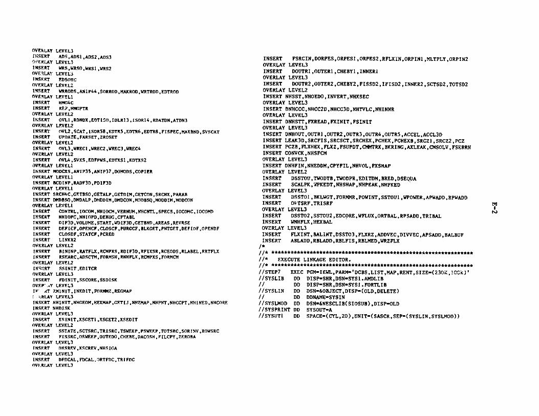
OVERLAY LEVEL3INSERT ADSADS I,ADS2,ADS3OVERLAY LEVEL3INSERT WRS,WRSOWRS1,WRS2OVERLAY LEVELINSERT EDSOECOVERLAY LEVEL2INSERT WRRODS,ANIP44 ,SORROD,MAKROD,WRTROD,EDTRODOVERLAY LEVELINSERT HMG4CINSERT RF.,HMGPTR
OVERLAY LEVEL2INSERT OVL1,RDNDX,EDTISO,IDLR13,ISOR14,RDATDN,ATDN3OVERLAY LEVEL2INSERT OVL2,SCAT, ISOR58,EDTR5,EDTR6,EDTR8,FISPEC,MAXBND,SVSCATINSERT UPDATE,FARSET,ZROSETOVERLAY LEVEL2INSERT OVL3,WREC1 ,WREC2 ,WREC3 ,WREC4OVERLAY LEVEL2INSERT OVL4,SVXS,EDFPWS,EDTXS1 ,EDTXS2OVERLAY LEVELINSERT MODCXS,ANIP35,ANIP37,DOMODS,COPIEROVERLAY LEVELINSERT RCDINP,RADF3D,PDIF3DOVERLAY LEVEL 1INSERT SRCH4C,GETBSO,GETALP,GETDIM,GETCON, SRCHX ,PARARINSERT DMDBSQ,DMDALP,DMDDIM,DMDCON,MODBSQ,MODDIM,MODCONOVERLAY LEVELINSERT CONTROL, IOCOM,NHIOCM,VERNUM,NHCNTL,SPECS, IOCOMC, IOCOMDINSERT NHIOPC,NHIOPD,DERUG,CFTABLINSERT DIF3D,VOLUME,START,WDIF3D,GETBND,AREAS,REVRSEINSERT DEFICF,OPENCF,CLOSCF,PURGCF,BLKGET,PNTGET,DEFIDF,OPENDFINSERT CLOSDF,STATCF,PCREDINSERT LINKR2OVERLAY LEVEL2INSERT BININP,RATFLX,RCMPXS,RDIF3D,RFIXSR,RGEODS,RLABEL,RRTFLXINSERT RSEARC,ADSCTM, FORMSH,RNHFLX ,RCMPXS ,FORMCMOVERLAY LEVEI.2INSERT! SSIN[TEDITCROVERLAY LEVEL3INSERT FDINIT,SSCORE,SSDISKOVEP' tY LEVEL3IF (T ZMINIT,INEDIT,FORMMZ,REGMAP
r.RLAY LEVEL3INSERT NHINIT,NHCEOM,HEXMAP,GETIJ,NHZMAP,NHPNT,NHCCPT,NHINED,NHCOREINSERT NHDISKOVERLAY LEVEL3INSERT XSINIT,XSCET1,XSGET2,XSEDIT
OVERLAY LEVEL2INSERT SSTATE,SCTSRC,TRISRC,TSWEEP,PSWEEP,TOTSRC,SORINV,ROWSRCINSERT FISSRC,OSWEEP,OUTEDO,CHERE,DACOSH,FILCPY,ZEROBAOVERLAY LEVEL3INSERT DXSREV,XSCREV ,NHSIGAOVERLAY LEVEL3INSERT DFDCAL,FDCAL, RTFDC,TRIFDCOVERLAY LEVEL3
INSERT FSRCIN,DORPES,ORPESI ,ORPES2,RFLXIN,ORPIN1 ,MLTPLY,ORPIN2OVERLAY LEVEL3INSERT DOUTR1 ,OUTER1 ,CHEBY1, INNEROVERLAY LEVEL3INSERT DOUTR2,OUTER2,CHEBY2,FISSD2,IFISD2,INNE R2 ,SCTSD2,TOTSD2OVERLAY LEVEL2INSERT NHSST,NHOEDO, INVERT,NHXSECOVERLAY LEVEL3INSERT DNHCCC,NHCC2D,NHCC3D,NHTVLC,NHINNROVERLAY LEVEL3INSERT DNHSTT,FXREAD,FXINIT,FSINITOVERLAY LEVEL3INSERT DNHOUT ,OUTR1 ,OUTR2,OUTR3,OUTR4 ,OUTR5,ACCEL,ACCL3DINSERT LEAK3D,SRCFIS,SRCSCT,SRCHEX,PCHEX,PCHEXB,SRCZl ,SRCZ2,PCZINSERT PCZB,FLXHEX,FLXZ,FSUPDT,CMMTRX,BKRING,AXLEAK,CMSOLV,FSERRNINSERT CONVCK,NHSFCMOVERLAY LEVEL3INSERT DNHFIN,NHEDDM,CPYFIL,NHVOL,FXSHAPOVERLAY LEVEL2INSERT DSSTOU,TWODTB,TWODPR,EDITDM,BRED,DSEQUAINSERT SCALPK, WPKEDT,NHSHAP,NHPEAK,NHPKEDOVERLAY LEVEL3INSERT DSSTO1 ,BKLWGT, FORMMR,POWINT, SSTOU1 ,WPOWER,APWADD,RPWADDINSERT OfTSRF,TRISRFOVERLAY LEVEL3INSERT DSSTO2,SSTOU2,EDCORE,WFLUX,ORTBAL,RPSADD,TRIBALINSERT WNHFLX,HEXBALOVERLAY LEVEL3INSERT FLXINT,BALINT,DSSTO3,FLXRZ,ADDVEC,DIVVEC,APSADD,BALBUFINSERT ABLADD,RBLADD,RBLFIS,RBLMED,WRZFLX
/*//* ***************************************************************
//* EXECUTE LINKAGE EDITOR./1* ***************************************************************
//STEP7 EXEC PGM-IEWL,PARM='DCBS,LIST,MAP,RENT,SIZE=(230i,!CCc)'//SYSLIB DD DISP=SHR,DSN=SYS1.AMDLIB/ /DD DISP-SHR,DSN-SYSI.FORTLIB//SYSLIN DD DSN=&OBJECT,DISP=(OLD,DELETE)// DD DDNAME-SYSIN//SYSLMOD DD DSN=&NESCLIB(SIOSUB),DISP-OLD//SYSPRINT DD SYSOUT=A//SYSUT1 DD SPACE-(CYL,20),UNIT-(SASCR,SEP-(SYSLIN,SYSLMOD))
[N1

Appendix F,1
SEGMENTED LOADER INSTRUCTIONS FOR SEGLINK ON THE CDC 7600
SEGLD3D, 7,400, 20000.XXXXXX
complexle source and pass LGO file to SEGLINK>
SFL,170000,100000.SEGLINK(FaLGO,PmFTN4LIB,BDDIF3D,LOBEX)
EXIT.
**
** TREE STRUCTURE DEFINITION WITH IMPLICIT INCLUDES""
ROOT TREE D3DRIV-(SCAN,STUFF,GNIP4,HMC4,MODCXS,BCDINP,SRCH4C,BININP,,SSINI,SSTAT,NHSS,DSSTO,UDOIT1,UDOIT2,UDOIT3,UDOIT4)
GNIP4 TREE GNIP4C-(RNTP1,FGEOD,EGEOD,RANIP2,FADENS,BCDXST,WSRCH,WSORC,WRRODS)RNIPI TREE RANIPI-(ANIPO3,ANIPHX,ANIPRI)FGEOD TREE FCEODS-(GETHCT,GETMSH,GETBUC,GETMR)ECEOD TREE EGEODS-(MAKMSH ,PRGEOD,ANIP43,HEXMP,ORTMAP)HEXMP TREE HEXMAP-(HEXPC4 ,HEXPC5)WSRCH TREE WRSRCH-(ANIP21,EDSRCH)WSORC TREE WRSORC-(ANIP19,SORDAT,ADS,WRS,EDSORC)s
HMG4 TREE HMC4C-(OVLI,OVL2,OVL3,OVL4)
SSINI TREE SSINIT-(FDINIT,ZMINIT,NHINIT,XSINIT)SSTAT TREE SSTATE-(DXSREV,DFDCAL,DORPES,DOUTRI,DOUTR2)
NHSS TREE NHSST-(DNHCCC,DNHSTT,DNHOUT,DNHFIN)
DSSTO TREE DSSTOU-(DSSTO1,DSSTO2,DSSTO3)"*
! EXPLICIT SEGMENT DEFINITIONSe"
D3DRIV INCLUDE D3DRIV,CRED,DOPC,DRED,DRED1,DRED2,ERROR,FEQUAT,FFORM,EC,MV,ECZERO, FFORMI ,FFORM2, FLTSET, IEQUAT, ICTLCM,JCTSCM,FRELCM, LOCFWD, INTSE,T,IN2LIT,LINES,POINTRPUTPNT,BULK,FREE,WIPOUT,GETPNT,IGET,IPT2,PUTM,IPT,ERR,ILAST,REDEF,REDEFM,PURGE,STATUS,PRTII,PRTI2,PRTRI,PRTR2,PRTECM,REED* ,ZEROIO,SEEK,SEKPHL,SPACE,SQUEZ.E,SRLAB,TIME.R,DIF3D,START,VOLUME,WDIF3D,,CETBND,AREAS,REVRSEDEFICFOPENCFCLOSCFPURCCF',BLKGETPNTCETDF!DFOP,ENDF,CLOSDF,STATCF,CODECD,READEC,WRITEC,PCRED
"
STUFF INCLUDE STUFF,STUFFI
CNIP4C INCLUDE GNIP4CANIPO1 ,ANIPO2,ANIPI4,ANIP23,CETZON,GETSZNAN!P03 INCLUDE ANIPO3,ANIPOI.,ANIPOS,ANIPO6ANIPHX INCLUDE ANIPHX,ANIP07,ANIPO9,CHEKO9,ANIP1OANIPlI INCLUDE ANIPIJ,ANIPI2,ANIPI5,ANIP34
FGFODS INCLUDE FCEODS,LOCHEX ,SETHEXGFTHGT INCLUDE CETHGT,GETREGCF.TMSH INCLUDE GETMSH,CMESH,FMESHGETBUC INCLUDE GETBUC,GETBCGETMR INCLUDE GETMR,RCHESH,TRIGOM,VOLREG,REDMSHPRGF.OD INCLUDE PRGEOD,PRNTIXANIP43 INCLUDE ANIP43,MPGEOD,MSHMAPTRIPL INCLUDE TRIPLT,HEXPIC,HEXPC1,HEXPC2,HEXPC3,HEXPC6,HEXPC7ORTMAP INCLUDE ORTMAP,ORTPCI ,ORTPC2 ,ORTPC3 ,ORTPC4 ,ORTPCS ,ORTPC6RANIP2 INCLUDE RANIP2,ANIP13,CETMAT,CETISO,ANIP39,CETSETFADENS INCLUDE FADENS,SORT13 ,VAI.U2D, SET2D, INDEX , EDTMAT, SORT14 ,WNDXSRBCDXST INCLUDE BCDXST,RWISOT,RWDF.LY,RWDY1,RWDY2ANIP21 INCLUDE ANIP2I,ANIP22,SRCH4D,ANIP24,SRCH3D,ANIP25,SRCH6D,ANIP26ANIP19 INCLUDE ANIPI9,ANIP40,ANIP41,ANIP42SORDAT INCLUDE SORDAT,SORLAB,SORMSH,SORNZN,SORDIFADS INCLUDE ADS,ADSI,ADS2,ADS3WRS INCLUDE WRS,WRSO,WRSI,WRS2WRRODS INCLUDE WRRODS,ANIP44,SORROD,SORMSH,SORNZN,SORDIF
*
HMG4C INCLUDE HMG4COVLI INCLUDE OVLI ,RDNDX,RDATDN,ATDN3,ISOR14,EDTISO,IDLR13OVL2 INCLUDE OVL2, 1SOR58 , SVSCAT, FARSET, ZROSET, UPDATE , MAXIIND, FISPEC, E,DTR5 ,EDTR6 ,EDTR8
OVL3 INCLUDE OVL3,WRECI,WREC2,WREC3,WREC4OVL4 INCLUDE OVL4,SVXS,EDTXS1,EDTXS2,EDFPWS
MODCXS INCLUDE MODCXS,ANIP35,ANIP37,DOMODS,COPIER*
BCDINP INCLUDE BCDINP,RADF3D,PDIF3D*
SRCH4C INCLUDE SRCH4C,GETBSQ,CETALP,GETDIM,GETCON,SRCHX,PARAB,DMDBSQ,D, MDA LP ,DMDD IM,DMDCON ,MODBSO ,MODD IM, MODCON
*
RININP INCLUDE BININP,RDIF3D,RLABEL,RSEARC,RCMPXS,ADSCTM,RGEODS,FORMSH,,RRTFLX,RATFLX,RFIXSR,RNHFLX,RCMPXS,FORMCM
*
SSINIT INCLUDE SSINIT,EDITCRFDINI INCLUDE FDINIT,SSCORE,SSDISKZMINIT INCLUDE ZMINIT,INEDIT,FORMMZ,RECMAPNHINIT INCLUDE NIINIT,NHGEOM,HEXMAP,CETIJ,NHZMAP,NHPNT,NHCCPT,NHINED,N,HCORE,NHDISKXSINIT INCLUDE XSINIT,XSGETI,XSGET2,XSEDIT
*
SSTATE. INCLUDE SSTATE,CHERE,DACOSH,OIJTF.DO,FILCPY,OSWF.P, PSWEEP,TSWEEP,SORINV,FISSRC,TOTSRC,SCTSRC,ROWSRC,TRISRC,ZEROBADXSREV INCLUDE DXSREV,XSCRF.VDFDCAL I NCLUIDE DFDCAL, FDCAL , RTFDC ,TRI FDCDORPF.S INCLUDE DORPES,ORPESI ,ORPIN1 ,RFLXIN,FSRCIN,O'PES2,ORPIN2,MLTPLYl)OUTR1 INCLUDE DOUTR I ,OUTERI , INNER ,CHEBY1DOUTR2 INCLUDE DOITR2,OUTER2, INNF.R2,CHEBY2,IFISD2,SCTSD2,TOTSD2,FISSD2
"-

NHSST INCLUDE NHSSTNHOEDO, INVF.RT,NHXSECDNHCCC INCLUDE DNHCCC,NHCC2D, NHCC2D, NHCC3D, NHTVLC ,NHINNRDNHSST INCLUDE DNHSST,FXREAD,FXINIT,FSINITDNHOUT INCLUDE DNHOUT,OUTRI,OUTR2,OUTR3,OUTR4,OUTR5,ACCELACCL3D,LEAK3,DSRCFIS,SRCSCTSRCHEX,PCHEX ,PCHEXB,SRCZISRCX2,PCZ,PCZB,FLXHF.X,FLXZ,FS,UPDTCIQTRXBKRING,AXLEAKCMSOLV, FSERRN, CONVCK,NHSFCMDNHFIN INCLUDE DNHFINNHEDDMCPYFIL,NHVOLFXSHAP
"
DSSTOU INCLUDE DSSTOU,TWODPR,TWODTBBREDDSEOUA,EDITDM,SCALPK,WPKF.DT,NHSHAP ,NPEAK,
DSSTOI INCLUDE DSSTOI,FORMMR,BKLWGT,SSTOUI,POWINT,RPWADD,APWADDWPOWER,ORTSRF,TRISRFDSSTO2 INCLUDE DSSTO2 ,EDCORE.SSTOU2,RPSADD,WFLUX,ORTBALTRIBALWNHFLX,DSSTO3 INCLUDE DSSTO3,ADDVECDIVVECBALINT,RBLADD,RBLMEDRBLFIS,ARLADD,,APSADD,FLXINT,FLXR7Z,WRZFLX"*
* GLOBAL COMMON BLOCK DECLARATIONSf*
GLOBAL STFARC,PTITLE, IOPUT,ARRAY,VERNUM, IOCOM, SPECS ,CONTRL, IOCO,MDDEBUG,IOC9dC,SINGLE,POINTSPNAMES,LOCATE,TNAMES,IDENTLABSPC,FILEID,
,NHCNTL ,NHIOCM,NNIOPC,NHIOPDGNIP4C GLOBAL BCDFLT,BCDINT,ISIZESHG.XMAP GLOBAL HEXPCORTMAP GLOBAL ORTPCHMC4C GLOBAL REF,HMGPTRDSSTOU GLOBAL EDITDMDSSTO3 GLOBAL BALBUF**
* END OF SEGLINK INPUT*
END D3DRIV
.1
N-

Appendix F.2
TYPE 01 OVERLAY DIRECTIVES FOR THE LDR LOADER ON THE CRAY-1
FILE,$BLD.OVLDN,DIF3D.SBCA,????. (ADDRESS OF LONGEST OVERLAY MUST BE OBTAINED FROM LOADER OUTPUT)
ROOT,D3DRIV,CRED,DOPC,DRED,ERROR,FEQUAT,FFORM,FFORM1,FFORM2,FLTSET,IEQUAT,IGTLCM,JGT,FRELCM,LOCF,LOCFWD,INTSET,IN2LIT,LINES,POINTR,PUTPNT,BULK,FREE,WIPOUT,GETPNT, IGET,IPT2,PUTM, IPTERR,
ILAST,REDEF,REDEFM,PURGE,STATUS,PRTI1,PRTI2,PRTR1,PRTR2,PRTECM,REED,ZEROIO, SEEK,SEKPHL, SPACE,SQUEZE,SRLAB,TIMER,DIF3D,START ,VOLUME,WDIF3D,
GETBND,AREAS,REVRSE,DEFICF,OPENCF,CLOSCF,PURGCF,BLKGET,PNTGET,DEFIDF,OPENDF,CLOSDF,STATCF,CODECD,PCRED.POVL,1,SCAN.POVL, 2 ,STUFF, STUFF .POVL,3,GNIP4C,ANIPO1 ,ANIP02,ANIPI4,ANIP23,GETZON,GETSZN,CPYLBG.SOVL,1,RANIP1,ANIPO3,ANIPO4,ANIP05,ANIP06,ANIPHX,ANIPO7,ANIPO9,CHEK09,ANIPIO,ANIPi ,ANIP12,ANIP15,ANIP34.SOVL,2,FGEODS,LOCHEX,SETHEX,GETHGT,GETREG,GETMSH, CMESH, FMESH, SRFLT,GETBUC,GETBC,GETMR,RCMESH,TRIGOM,VOLREG,REDMSH.SOVL,4 ,EGEODS,MAKMSH,PRGEOD,PRNTIX,ANIP43,MPGEOD, MSHMAP ,TRIPLT,HEXPIC,HEXPC1 ,HEXPC2,HEXPC3,HEXPC6,HEXPC7,HEXPC4,HEXPC5,ORTMAP,ORTPC1,ORTPC2,ORTPC3,ORTPC4,ORTPC5,ORTPC6.SOVL,4,RANIP2,ANIP13, GETMAT,GETISO,ANIP39,GETSET.SOVL,5,FADENS,SORT13,VALU2D,SET2D,INDEX,EDTMAT,SORT14,WNDXSR.SOVL,6,BCDXST,RWISOT,RRWDELY,RWDY1 , JDY2.SOVL,8,WRSRCH,ANIP21 ,ANIP22,SRCH4D,ANIP24,SRCH3D,ANIP25,SRCH6D,ANIP2
6,
EDSRCH.SOVL,7,WRSORC,ANIP19,ANIP40,ANIP41,ANIP42,SORDAT,SORLAB,SORMSH,SORNZN,SORDIF,ADS,ADS1 ,ADS2,ADS3,WRS,WRSO,WRS1,WRS2,EDSORC.POVL,4,HMG4C.SOVL,1,OVL1,RDNDX,RDATDN,ATDN3,ISOR14,EDTISO,IDLR13.SOVL, 2,0VL2, ISOR58, SVSCAT, FARSET, ZROSET, UPDATE,MAXBND, FISPEC, EDTR5,EDTR6,EDTR8.
_ SOVL,3,OVL3,WREC1,WREC2,WREC3,WREC4.SOVL,4,OVL4,SVXS,EDTXS1,EDTXS2,EDFPWS.POVL,5,MODCXS,ANIP35,ANIP37,DOMODS,COPIER.POVL,21,BCDINP,RADF3D,PDIF3D.POVL,6,SRCH4C,GETBSQ,GETALP,GETDIM,GETCON,SRCHX,PARAB,DMDBSQ,DMDALP,DMDDIM,DMDCON,MODBSQ,MODDIM,MODCON.POVL,22,BININP,RDIF3D,RLABEL,RSEARC,RCMPXS,ADSCTM,RGEODS,FORMSH,FORMCM,RRTFLX,RATFLX,RFIXSR,RNHFLX.POVL,23, SSINIT,EDITCR.SOVL,1,FDINIT,SSCORE,SSDISK.SOVL,2,ZMINIT,INEDIT,FORMMZ,REGMAP.SOVL,3,NHINIT,NHGEOM,HEXMAP,GETIJ,NHZMAP,NHPNT,NHCCPT,NIIINED,NHCORE,NHDISK.SOVL, 4, XSINIT, XSGET1, XSGET2, XSEDIT.POVL,24,SSTATE,CHEBE,DACOSH,OUTEDO,FILCPY,OSWEEI,PSWEEP,TSWEEP,SORINV,FISSRC,TOTSRC,SCTSRC,ROWSRC,TRISRC,ZEROBA,RBOSOR,RBOSRC.SOVL,1,DXSREV,XSCREV,NHSIGA.SOVL, 2, DFDCAL, FDCAL, ORTFDC, TRIFDC.SOVL,3,DORPES,ORPES1 ,ORPIN1 ,RFLXIN,FSRCIN,ORPES2,ORPIN2,MLTPLY.SOVL,4,DOUTR1,OUTER1,INNER1,CHEBY1.SOVL,5,DOUTR2,OUTER2,INNER2,CHEBY2,IFISD2,SCTSD2,TOTSD2,FISSD2.POVL,25,NHSST,NHOEDO,INVERT,NHXSEC.SOVL,1,DNHCCC,NHCC2D,NHCC3D,NHTVLC,NHINNR.SOVL,2,DNHSTT,FXREAD,FXINIT,FSINIT.SOVL,3,DNHOUT,OUTRi,OUTR2,OUTR3,OUTR4,OUTR5,ACCEL, ACCL3D, LEAK3D,SRCFIS,SRCSCT,SRCHEX,PCHEX,PCHEXB,SRCZ 1,SRCZ2 ,PCZ,PCZB,FLXHEX, FLXZ,FSUPTD, CMMTRX, BKRING, AXLEAK,CMSOLV, FSERRN, CONVCK.SOVL, 4,DNHFIN,NHEDDM,CPYFIL,NHVOL,FXSHAP.POVL,29,DSSTOU,TWODPR,TWODTB,BRED,DSEOUA,SCALPK,WPKEDT,NHSHAP,NHPEAK,NHPKED.SOVL,1,DSSTO1,FORMMR,BKLWGT,SSTOU1,POWINT,RPWADD,APWADD,WPOWER,ORTSRF,TRISRF.SOVL, 2,DSSTO2 ,EDCORE, SSTOU2,RPSADD,WFLUX,ORTBAL,TRIBAL,WNHFLX,HEXBAL.SOVL,3,DSSTO3,ADDVEC,DIVVEC,BALINT,RBLADD,RBLMED,RBLFIS,ABLADD,APSADD, FLXINT, FLXRZ ,WRZFLX.
F-+

G.1-1
Appendix G
SAMPLE PROBLEM OUTPUT
G.1 Sample Problem 1 (entire output)
SCAN 1/05/A4 2221.700 PACE
CE INPUT FILE -PRINT FILE - 6AlIILIAI) PINT FILE - 10
KC INPUT
ULOCE-STP02IUNFONN-A.01F1D
01 """" SAMPLE PROBLEM I *"" 2D SWNE.NCIANIA--00 IN -F002 1300 6000
01 0000)000 1 0 011111 10 100 10 0
06 1.0 0.001 0.04 0.UNI9IMA.NIP1
01 " ".4SAOPLE PFOLE I """* 2I0 N1I6ENCLINAO - NOS IN -F110602 0 1 10000 010000an 0 0 101 1004 7 40 40) 1U0.5000 1 400 U .000 1 407 TCOIE IC SC07 T00 C3 CF
07 TOTAL IC oC I CU CF
14 Ml II I.0
14 92 1 1.014 M) I) 1.014 M4 14 1.014 MS I 1.014 16 14 1.0IS M IC
I) N) 33IS M C1I 11 C
29 1 11.00) 1 I30 I I
10 IC 210 IC )10 IC 410 IC 5
10 IC 410 OC 4I10 007610 nC7
10 13 910 S1Il10 I1 9 I10 C N A10 0C 9 4 50 M0 94144
30 1 111% 5710 C171 I10 CI 7 1)
10 CF 4 I41 1 0 0 .6N060T A. 110
V ISOTS 62 *0F1 30 NC " I
SCAN 1/0/84 2221.700 FACE 2ID 4 4 0 1 0 I I 170 *NA C0ILEE F I NEINCSINANE 003 CUP COS) SECTIONS
*I11 12 I 14 I) 160.74 0.12 0.0 0.0
.721E+09 4.0441E+06 7.9700E+07 ).I946E+07 1.01 E+ 7 6.00 1.0)0140. 1000. 0.0
0 )1 64 9 7II SI40 I C I100. 0.0 0.0 0.0 0.0 0.00 n0 1I n 0 0 0 D 0 I I 0 00
I I 2 1 4 I I I I50 .111 .21120 .44117 .1471 .1111
.17n 4117 .14177 .4091-0 1.)0511.-01 .92944 9-1 F.17)0 E-01 .19121 E-02 .1126 E-02 .1414 1-02 .9141 E-02 1.00662.912171 2.419174 2.179)1170 0.0 0.0 .0)19 0. .11) E-0l.40791 -0 0.0 .4611 E-02 .42)09 E-07 .44491 E-0740 12 00P I00. 0.0 0.0 0.0 0.0 0.0
0 0 1 0 0 0 0 0 I I 0 200I I 2 1 4 I I I I
SD .1119 .1211 .4470 .1149 .1111.21211 .4470 .1149 .671 E-01."1914 1-01 1.00114E-02.20474 F-01 .411 E-02 .4177 1-02 .1112 E-02 .1121 2-01 1.0790 1
2.914926 .14. .112170 0.0 0.0 .02122 0.0 .1)716 E-02.4441 E-05 0.0 .4114 -0 .4074 1-07 .499469 1-0740 11 c00 I100. 0.0 0.0 0.0 0.0 0.0
0 0 1 0 0 0 0 0 I I 0 200I I 2 1 4 I I I
16 .1491 .29441 .2701 .40712 .1414.26441 .1270) .40712 1.ll271-011.0341441-01.001141-02
.12999)-01 .27668 E-02 .4447 1-04 .12274 1-01 .149)2 1-01 2.794102.440977 2.421171 2.4229 177 0.0 0.0 .01201 0.0 .1774 1-02.1)460 1-0) 0.0 .14971 1-02 .90016 1-07 .41039 1-0lA9 14 c0 I100. 0.0 0.0 0.0 0.0 0.0
0 0 I 0 0 0 0 0 I I 0 200I I 2 1 4 I I I I
00 .12270 .2111 .4 274 .1 7 49 .121 0.7111 .44274 .11749 6.227 1-442.70N13-0 7.6401-0119718 1-02 .1941 1-02 .11011 1-04 .6714 3-04 .21769 1-01 2.7902442.4110 2.421000 2.42196673 0.0 0.0 .02122 0.0 .2269 1-02.2907 3-0) 0.0 .1)4 1-02 .21 1-07 .11846 1-074& I 000 I100. 0.0 0.0 0.0 0.0 0.0
0 0 0 0 0 0 0 0 I I 0 200I I 2 3 4 I I I I
10 .11117 .21311 .14044 .1410 .11311.2)3)1 .11044 .1416 .10644941-02 .126411-01 .41)40!E-01
70 0.0 0.0 .012946 0.0 .)177 1-02.10110 1-01 0.0 .6461 -02 .70361 1-lI .10689 3-07406 34 001 I100. 0.0 0.0 0.0 0.0 0.0

G.1-2
SCAN 1/05/84 2221.700 PACE 3
0 0 0 0 0 0 0 0 1 0 200I 3 2 3 4 I 3 1 1 1
SD .072206 .11487 .32642 .19272 .072206.1487 .32642 .19272 .216305E-03 .16880 E-03 .1468 E-02.78660 E-037D 0.0 0.0 .012942 0.0 .12871 E-02
.68780 E-06 0.0 .34533 1-02 .43633 E-11 .69903 E-0NBLOCK-STPO21.3REMOVE-CF.OSTREOVE-COMPSREMOVE-NDSRFREOVE-ZNATDMREOVE-LA6ELSR.MOVE-RTFLUXREMOVE0DIF3D600IFY-A.03 3001 """SAMPLE PROBLEM 2 "" 20 SNR BENCAE - RODS IN - NODAL02 6000 570004 1000033 10 1001 0 011 14 0.0 3 87.5 3 135.011 1 175.0ODIFY-A.NIP3
01 " SAMPLE PROBLEM 2 """ 2D NR ECI6ARK - RODS IN - NODAL02 03100000 1000 0 0 0 0 003 11443-DELETENLOCK-STPO23.3REMOVE-CEODSTIEMOVE-COMPSRFP60E-NOS6FREM"Z-ZNATDNREMOVE-LABELSREMOVE-RTFLUREMOVE-NHILUXKREMOVE.-D I 3DUN.0RM-A.D1730
01 "" SAMPLE PROBLEM "" 3D SNE BENCHMARK - RODS IN6- NODAL02 20000 27000 003 000645000004 1 0 0 00 3n 10 0 1 0 000 3.0E-7 1.0E-5 1.0E-06 1.0 0.001 0.04 0.511 14 0.0 1 87.5 3 135.0II 175.0UN7ORM-A.NIP301 "" SAMPLE PROBLEM. "" 3D SN BENCHMARK - 8 PLANES - NODAL02 0 I 8000 01000 0 0 0 0 003 12406 760666405 U .5000 1 405 Y 3 .5000 1 405 Z. .5000 1 400 ZU .5000 1 409 Z 2 40.0 2 87.5 2 135.009 Z 2 175.014 63 33 3.014 2 12 1.014 3 33 1.0
SCAN 1/05/84 2221.700 PACE 4
14 6 14 1.014 MS 15 1.014 66 16 1.030 M3 IC30 M2 OC30 63 RB30 66 A30 60 CR
30 66 CF29 33.2003 I I30 A 1 0 0 0.0 175.030 IC 1 0 0 40.0 135.030 A6 2 0 0 0.0175.030 IC 2 n 0 40.0 135.030 AR 3 0 0 0.0 175.030 IC 3 0 0 40.0 135.030 A 4 0 0 0.0 175.030 IC 4 0 0 40.0 133.030 AR 5 0 0 0.0 173.030 IC 5 0 0 40.0 135.030 AU 6 0 0 0.0 175.030 IC 6 0 0 40.0 135.030 AU 7 0 0 0.0 175.030 OC 7 0 0 40.0 135.030 A 8 0 0 0.0175.030 OC 6 0 0 40.0 35.030 i U 9 0 0 0.0 175.030 R 30 0 0 0.0 170.030 AB 6 1 I 0.017.030 OC 6 1 3 40.0 35.030 NB 6 3 I 0.0 170.030 A 6 9 4 5 0.0 75.030 OC 6 5 40.0135.030 A 9 45 46 0.0 170.030 OC 9 60 46 40.0 135.030 R 0 11 5 6 0.0 170.030 R 0 11 56 57 0.0 170.030 CF 6 4 1 0.0 135.030 CF 7 3 3 0.0 87.530 CF 7 35 33 0.0 67.530 cR 6 3 3 35.0 170.030 CR 7 3 3 87.5 170.030 CR 7 15 35 87.5 175.0RLOCK-STPO21 .3REMOVE-CE00RT
ENOV-c31WP1RELUE-ND1BF116V33-ZNATDNRKSUVSLAUELI
RINOV-ETFLUUENOV-NFLUOREND6VROI3DODIF-A.DI37D01 " BAMWLE PROBLEM 6 """ 3D 363 BENC6U6ARK - 1003 I6 - P0063602 12000 166000MODIF-A.NIP301 "" SAMPLE PROBLEM 4 6 3D 63 3D R NCMIAI - B 16008 IN -MP063603 90
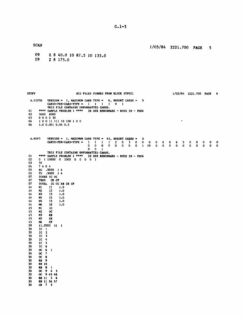
G.1-3
1/05/84 2221.700 PAGE 5
Z 8 40.0 10 87.5 10 135.0Z 8 175.0
BCD FILES FORMED FROM BLOCK STPO21 1/05/84 2221.700 PAGE 6
A.DIF3D VERSION - 1, MAXIMUM CARD TYPE - 6, NOSORT CARDS - 0CARDS-PER-CARD-TYPE - 1 1 1 1 0 1THIS FILE CONTAINS UNFORMATTED CARDS.
01 **** SAMPLE PROBLEM 1 **** 2D SNR BENCHMARK - RODS IN - FD0602 3600 600003 0 0 0 0 3004 1 0 0 11 111 10 100 1 0 006 1.0 0.001 0.04 0.5
A.NIP3 VERSION -CARDS-PER
THIS FILE**** SAMPLE PR(0 1 10000 0707 4 0 4XU .5000 1 4YU .5000 1 4TCORE IC OCTROD CR CFTOTAL IC OC RIM1 Il 1.(M2 12 1.4M3 13 1.4M4 14 1.4M5 15 1.4M6 16 1.4M1 ICM2 OCM3 RBM5 CRM6 CF11.2003 11 1IC 1IC 2IC 3IC 4IC 5IC 6OC 6 10C 7OC 8RB 9RB 10RD 8 1OC 9 4 5OC 9 45 46RD 11 5 6RD 11 56 57CR 7 3
1, MAXIMUM CARD TYPE - 43, NOSORT CARDS - 0-CARD-TYPE - 1 1 1 1 2 0 3 0 0 0
0 0 0 0 0 0 0 0 1 190 0 1
CONTAINS UNFORMATTED CARDS.OBLEM 1 **** 2D SNR BENCHMARK - RODS IN - FD06
1000 0 0 0 0 1
0 0 0 6 5 0 0 0 0 00 0 0 0 0 0 0 0 0 0
B CR CF000000
SCAN
0909
STUFF
0102030405050707071414141414141515151515293030303030303030303030303030303030

G.1-4
STUFF BCD FILES FORMED FROM BLOCK GTP021 1/05/84 2221.700 PAGE 7
30 CR 7 3530 CF 4 143 1 0 0 .6
A.ISO VERSION - 1, MAXIMUM CARD TYPE - 0, NOSORT CARDS - 66CARDS-PER-CARD-TYPE - 0
OV ISOTXS HH2 *GFK 3D BNCH * 1ID 4 6 0 3 0 1 1 12D *NA COOLED FBR BENCHMARK FOUR GROUP CROSS SECTIONS *
* * 11 12 13 14 I5 160.768 0.232 0.0 0.01.72336E+09 4.02463E+08 7.97003E+07 3.15946E+07 1.05 E+07 8.00 E+0510000. 1000. 0.0
0 3 6 9 12 154D I GFK 1100. 0.0 0.0 0.0 0.0 0.0
0 0 1 0 0 0 0 0 1 1 0 2001 1 2 3 4 1 1 1 1
SD .11587 .21220 .46137 .34571 .11587.21220 .46137 .34571 .69059 E-031.830758E-03 .92948 E-02.17305 E-01 .39123 E-02 .18286 E-02 .36334 E-02 .92415 E-02 3.0360662.912173 2.881874 2.8795117D 0.0 0.0 .023597 0.0 .16153 E-02.40791 E-05 0.0 .46838 E-02 .42309 E-07 .44493 E-074D 12 GFK 1100. 0.0 0.0 0.0 0.0 0.0
0 0 1 0 0 0 0 0 1 1 0 2001 1 2 3 4 1 1 1 1
SD .11588 .21213 .46770 .35349 .11588.21213 .46770 .35349 .66221 E-031.83956 E-03 1.00354E-02.20476 E-01 .48531 E-02 .26377 E-02 .51332 E-02 .13238 E-01 3.0790632.914926 2.884945 2.8825357D 0.0 0.0 .023262 0.0 .15718 E-02.46451 E-05 0.0 .43414 E-02 .40724 E-07 .49968 E-074D 13 CFK 1100. 0.0 0.0 0.0 0.0 0.0
0 0 1 0 0 0 0 0 1 1 0 2001 1 2 3 4 1 1 1 1
5D .14584 .28443 .52703 .40732 .14584.28443 .52703 .40732 1.11527E-033.063463E-031.002116E-02.129995E-01 .27688 E-02 .44347 E-04 .12274 E-03 .34952 E-03 2.7964102.440977 2.423171 2.4229517D 0.0 0.0 .032071 0.0 .27776 E-02.38880 E-05 0.0 .58971 E-02 .90018 E-07 .45039 E-074D 14 GFK 1100. 0.0 0.0 0.0 0.0 0.0
0 0 1 0 0 0 0 0 1 1 0 2001 1 2 3 4 1 1 1 1
5D .12270 .23133 .46274 .33749 .12270.23133 .46274 .33749 8.2278 E-042.170873E-03 7.64083E-03.97185 E-02 .19453 E-02 .31065 E-04 .87566 E-04 .23769 E-03 2.7902642.441880 2.423086 2.4229887D 0.0 0.0 .026322 0.0 .21889 E-02.28907 E-05 0.0 .53536 E-02 .62133 E-07 .33248 E-074D 15 FK 1
STUFF
100.
BCD FILES FORMED FROM BLOCK STPO21
0.0 0 ).0 0.00 0 0 0 0 0 0 c1 1 2 3 4 1 1 1
5D .13317 .25355 .58044 .54168.25355 .58044 .54168 .186696E-0.168687D 0.0 0.0 .022946 0.0.10320 E-05 0.0 .86815 E-02 .70361 E-114D 16 GFK 1100. 0.0 0.0 0.0
0 0 0 0 0 0 0 01 1 2 3 4 1 1
SD .072206 .11487 .32642 .19272.11487 .32642 .19272 .216305E-03.78660 E-037D 0.0 0.0 .012942 0.0.68780 E-06 0.0 .34533 E-02 .43633 E-11
SUBROUTINE STUFF USED 2048 WORDS OF CORECP TINE- 0.38 SECONDS, PP TIME- 0.0 SECONDS
1/05/84 2221.700 PAGE 8
0.0 0.00 1 1 0 2001 1
.133172 .126433E-01 .634405E-01
.37687 E-02.10489 E-07
o,
D
1
3,
1,
.0 0.01 1 0 200
.072206.16880 E-03 .11468 E-02
.12871 E-02.69903 E-08

G.1-5
**** SAMPLE PROBLEM 1 **** 2L SNR BENCHMARK - RODS IN - FD06 1/05/84 2221.700 PAGE 9
*** GNIP4C - GENERAL NEUTRONICS BCD INPUT PROCESSOR TO CREATE CCCC BINARY INTERFACE FILES ***
*** GNIP4C CONTROL PARAMETERS ***
IMAING NO. OF WORDS OF MAIN MEMORY REQUESTEDIBULKG NO. OF WORDS OF BULK MEMORY REQUESTEDIPRNTG BPOINTER TRACE AND DUMP CONTROL (0/1/2/3, NEITHER/DUMP/TRACE/BOTH)IGMEDT GEOMETRY PROCESSING EDIT CONTROL (0/1/2/3, NO EDITS/PRINT EDITS/EDITS TO AUXILIARY FILE/BOTH)IMAPR REGION MAP OPTION (0/1/2/3, NO MAP/PRINT MAP/MAP TO AUXILIARY FILE/BOTH)IMAPZ ZONE (COMPOSITION) MAP OPTION (0/1/2/3, SEE IMAPR)
*** MODEL DESCRIPTION ***
GNIP4C 11/83
1000000
0
965
3116311642
2
24
00
1.1200D+016.4665D+00
GEOMETRY TYPE, TRIANGULARNO. OF ZONES (COMPOSITIONS)NO. OF REGIONSNO. OF ZONE CLASSIFICATIONSNO. OF 1ST DIMENSION COARSE MESH INTERVALSNO. OF 2ND DIMENSION COARSE MESH INTERVALSNO. OF 1ST DIMENSION FINE MESH INTERVALSNO. CF 2ND DIMENSION FINE MESH INTERVALSFIRST BOUNDARY CONDITION, FIRST DIMENSION, PERIODIC, NEXT FACE CLOCKWISELAST BOUNDARY CONDITION, FIRST DIMENSION, EXTRAPOLATEDFIRST BOUNDARY CONDITION, SECOND DIMENSION, PERIODIC, SEE IMBILAST BOUNDARY CONDITION, SECOND DIMENSION, EXTRAPOLATEDNO. OF BUCKLING SPECIFICATIONSNO. OF CONSTANTS FOR EXTERNAL BOUNDARIESNO. OF CONSTANTS FOR INTERNAL BOUNDARIESNO. OF BLACKNESS THEORY ZONES0/1, REGION ASSIGNMENTS TO COARSE/FINE MESHOUTER BOUNDARY SHAPE, 60 DEGREE RHOMBUSORIENTATION OF (1,1) MESH TRIANGLE - POINTS AWAY FROM 1ST DIMENSION AXISHEXAGON FLAT-TO-FLAT DISTANCELENGTH OF MESH-TRIANGLE SIDE
EXTERNAL BOUNDARY CONDITION CONSTANTS C (D * DEL PHI - C * PHI), BY GROUPLAST VALUE SHOWN IS USED FOR REMAINING GROUPS
LAST TRIAGE BOUN
1 5.000000-01
LAST BOUN
1 5.000OOD-01
GNIP4C 11/83 ***
REGIONNO.
12345
REGIONNAME
ICOCRBCRCF
DARY
2 5.00000D-O1 3 5.00000D-01 4 5.00000D-01
DARY
2 5.00000D-01 3 5.00000D-01 4 5.00000D-01
SAMPLE PROBLEM I *** 2D SNR BENCHMARK - RODS IN - FD06 1/05/84 2221.700 PAGE 10
REGION/ZONE SPECIFICATIONS
REGION ZONE ZONE ZONEVOLUME NO. NAME CLASS. BUCKLING BY GROUP (REPEAT LAST VALUE FOR REMAINING GROUPS)
1.430E+03 1 Ml 0 0.01.521E+03 2 M2 0 0.01.955E+03 3 M3 0 0.02.173E+02 5 M5 0 0.01.086E+02 6 M6 0 0.0
INTERNAL BOUNDARY CONDITION CONSTANTS C (D * DEL PHI - C * PHI), BY GROUPLAST VALUE SHOWN IS USED FOR REMAINING GROUPS
1 0.0
REGIONS COMPRISING AREAS
REGION REGIONNO. NAME NO. NAME
3 Rd 4 CR
REGIONNO. NAME
5 CF
REGION REGIONNO. NAME NO. NAME
IGOMNZONENREGNZCLNCINTINCINTJNINTININTJIMB1IMB2JMB1JMB2NBSNBCSNIBCSNZWBBNRASSNTRIAGNTHPTFLATSIDE
AREANO. NAME
1 TCORE2 TROD3 TOTAL
REGIONNO. NAME
I IC4 CRI IC
REGIONNO. NAME
2 OC5 CF2 OC

G.1-6
-17 -15 -13 -11 -9 -7 -5 -3 -1 1 3 5 7 98 11 13 15
16 R, 616
15 RB 515
14 Ai, 5 14M3
13 ,1 5 , e 13
12 pM,. ,3312
1 R 3R 2 11
10 M , ,y3M, 2 Ra 1 10
9 S3 . 2M,0 1
8 B3 , 2 , 1 . 54 8
7 M 3 . 2 i 1e, 8 7
6 . 2 - M, 1 M 42 , 53 6
5 52
.1 M5367474 1 0 2 c, 1 M? 30 M, 41, 52 4
3 M, 1 ,. 24 to 35 0, 46 . 57 3
2 1 ,.18 , 29 , 40 , 51 2
1 , 1 ,.12 , M 23, M,340,5 , 56 1
1 3 5 7 9 11 13 15 17 19 21 23 25 27 29 31 33
GN1P4C Generated Calcomp 780 Plot of 2D SNR Benchmark Model
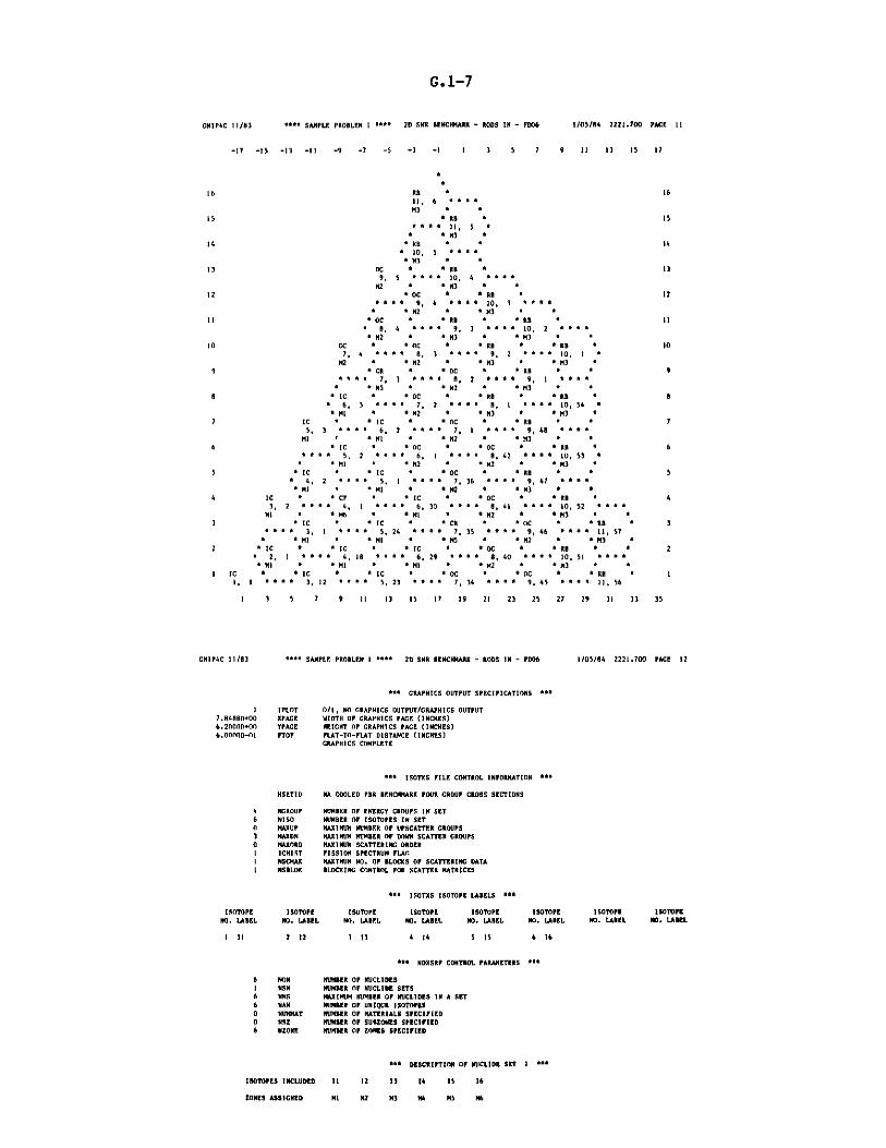
G.1-7
CNIP4C 11/833 ** SAMPLE PROBLEM I *** 2D SNR BENCHMARK - RODS IN - FD06 1/05/84 2221.700 PACE 11
-17 -15 -13 -11 -9 -7 -5 -3 -1 1 3 5 7 9 33 13 I5 17
16 RD 0 1611, 6 aaa"M3 * "
15 * RB a 15* 311, 5 *
" "1X3 a
14 RB * a 14I 10, 5 " * ra*"1M3 a a
13 C *RR a 139, 5 * "a*aa 10, 4 aaaa
M a *43 * *
12 OC I" * RRB * 12*h* 9, 4 * h 10, 3 a**
a * M2 " * M3 aII *OC h * R R*R a 1
a 8, 4 aa 9 9 a3 * a*a 10, 2 a" aa M2 a * M3 I 14M3 a a
10 C h IOC * R a " R a 107, 4 aa* 3 aa* 9, 2 aaa 3"10, 3 a
M2 * M2 * "a M3 * M3 a9 *CR a * rOC h " *RR a a"9
a a " , 3 * a * 8, 2 aa* 9, 1 " a"a *4M5 a * M2 a a"M3 * *
B " IC " " OC " " RB " " RB * Ba 6, 3 **a 7, 2 aaa "" ., a1 a a 10, 54*M a 1M2 a * M3 * "a M3a r
7 IC * IC a * C * RD * * 75, 3 ** * 6, 2 "a* 7, 1 aaa 9,48 a aa
Ml a MI a * M2 * * M3 * a6 aIC * *oc a" a"oc * R a 6
* * * * 5, 2 a a a a 6, a a * a a, 42 a a a a 10, 53 aa aMl a 11M2 a a
1M2 a h
1M3 a
S aIC * IC a * OC * * RD * *5a 4, 2 *hh * 5, 1 "aa a 7, 36 * e la 9,47 aa*aa1 4 aI Ml h " 1M2 a aM3 a a
4 C * * CF a arc a" hoc a a"RB * 43, 2 *a * a 4, 1 * 1"1"*" 6,730 aa* a R"* 8, 41" aaaa * 10, 52 * aaI a M6 * M 4*M2 a hM3 a a
3 a C * aIC a a"CR a OC a a"RD * 3a a a a 3, a a a a 5, 24 a a a 7, 35 a a a * 9, 46 a a a 11 57
a 1MI a a*MI a *a5 a *12 I * M3 *2 IC * *
1C * * IC * a aOC a aRB a 2
a 2,1 aa* 4,318 aaaa 6, 29 *a * 8, 40 a " 10, 51 ""a"14 * a M a* 14M3 a 14M2 a a M3 * *
IC a aC a C a OC * c aC * a"R *1,1 a a 3, 12 * a * 5 23 a a* 7, 34 a a " 9, 45 a a a a 11, 56
l 3 5 7 9 11 13 3 5 17 19 21 23 25 27 29 31 33 35
cNIP4C 11/83 6a6a SAMPLE PROBLEM 1 aa* 2D SNR BENCHMARK - RODS IN - FD06 1/05/84 2221.700 PACE 12
aaa GRAPHICS OUTPUT SPECIFICATIONS aaa
I PLOT 0/1, NO GRAPHICS OUTPUT/GRAPHICS OUTPUT7.84980+00 SPACE WIDTH OP GRAPHICS PAGE (INCHES)6.20000+00 YPACE HEIGHT OP GRAPHICS PACE (INCHES)
6.00000-01 TOF FLAT-TO-PLAT DISTANCE (INCHES)GRAPHICS COMPLETE
** ISOTXS FILE CONTROL INFORMATION aaa
SETID NA COOLED FBR BENCHMARK FOUR GROUP CROSS SECTIONS
4 NGROUP NUMBER OF ENERGY GROUPS IN SET6 100 NUMBER OF ISOTOPES IN SET0 MAXUP MAXIMUM NUMBER OF UPSCATTER GROUPS3 MAXON MAXIMUM NUMBER OF DOWN SCATTER GROUPS0 MAXORD MAXIMIUM SCATTERING ORDERI ICHIST FISSION SPECTRUM FLAGI NSCMAX MAXIMUM NO. OF BLOCKS OP SCATTERING DATAI NSBLOK BLOCKING CONTROL FOR SCATTER MATRICES
** ISOTXS ISOTOPE LABELS **
ISOTOPE ISOTOPE ISOTOPE ISOTOPE ISOTOPE ISOTOPE ISOTOPE ISOTOPENO. LABEL NO. LABEL NO. LABEL NO. LABEL NO. LABEL NO. LABEL NO. LABEL NO. LABEL
3 11 2 12 3 13 4 14 5 15 6 16
** NDXSRF CONTROL PARAMETERS **
6 MON NUMBER OF NUCLIDESI NSN NUMBER OF NUCLIDE SETS6 NNS MAXIMUM NUMBER OF NUCLIDES IN A SET6 NAN NUMBER OP UNIQUE ISOTOPES0 NUHMAT NUMBER OF MATERIALS SPECIFIED0 NSZ NUMBER OF SUEZONES SPECIFIED6 NZONE NUMBER OF ZONES SPECIFIED
*l DESCRIPTION OF NUCLIDE SET I **
ISOTOPES INCLUDED II 12 I 14 15 16
ZONES ASSIGNED MI M2 M3 M4 MS Mb
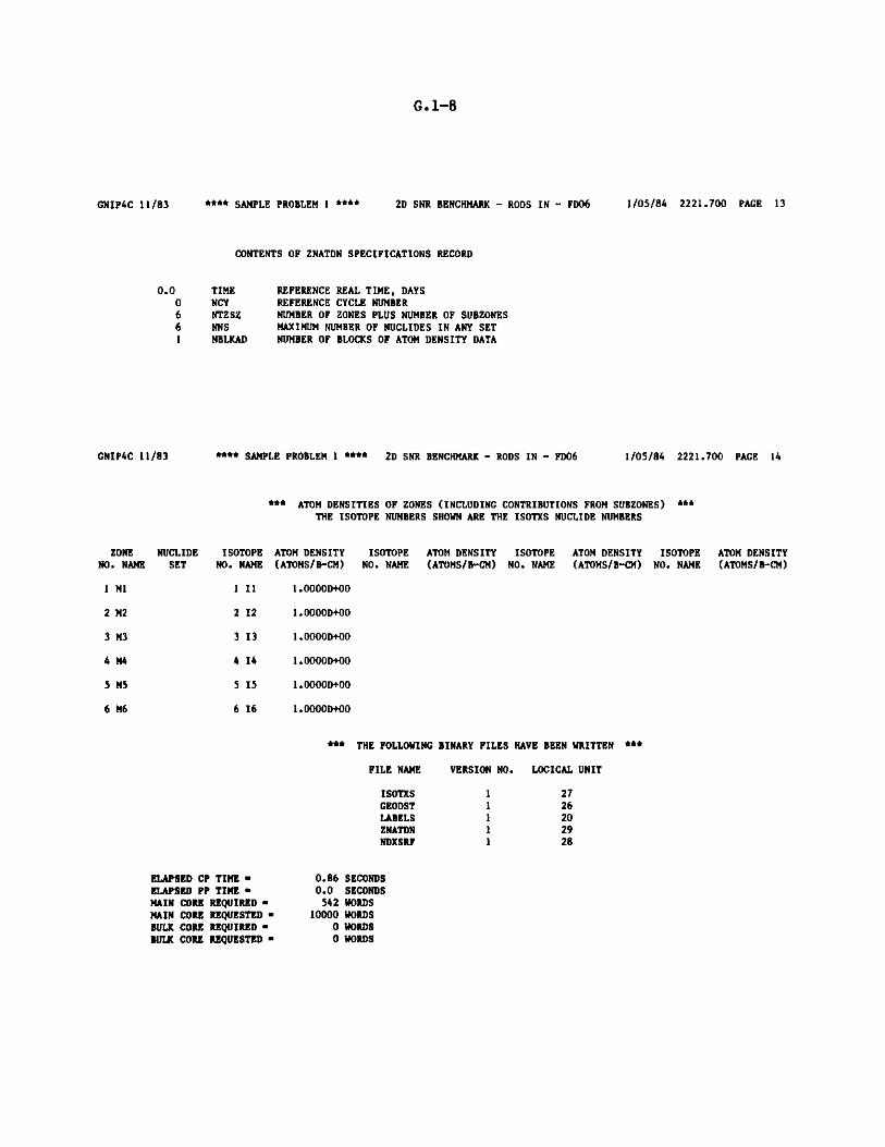
G.1-8
GNIP4C 11/83 **** SAMPLE PROBLEM 1 **** 2D SNR BENCHMARK - RODS IN - FD06 1/05/84 2221.700 PAGE 13
CONTENTS OF ZNATDN SPECIFICATIONS RECORD
TIME REFERENCE REAL TIME, DAYSNCY REFERENCE CYCLE NUMBERNTZSZ NUMBER OF ZONES PLUS NUMBER OF SUBZONESNNS MAXIMUM NUMBER OF NUCLIDES IN ANY SETNBLKAD NUMBER OF BLOCKS OF ATOM DENSITY DATA
GNIP4C 11/83 **** SAMPLE PROBLEM 1 **** 2D SNR BENCHMARK - RODS IN - FD06
ZONE NUCLIDE ISOTOPENO. NAME SET NO. NAME
1 M1 1 I1
2 M2 2 12
3 M3 3 13
4M4 414
5 M5 5 15
6M6 616
1/05/84 2221.700 PAGE 14
** ATOM DENSITIES OF ZONES (INCLUDING CONTRIBUTIONS FROM SUBZONES) ***THE ISOTOPE NUMBERS SHOWN ARE THE ISOTXS NUCLIDE NUMBERS
ATOM DENSITY ISOTOPE ATOM DENSITY ISOTOPE ATOM DENSITY ISOTOPE ATOM DENSITY(ATOMS/B-CM) NO. NAME (ATOMS/B-CM) NO. NAME (ATOMS/B-CM) NO. NAME (ATOMS/B-CM)
1.0000D+00
1.0000D+00
1.0000D+00
1.0000D+00
1.0000D+00
1.0000D+00
*** THE FOLLOWING
FILE NAME
ISOTXSGEODSTLABELSZNATDNNDXSRF
ELAPSED CP TIME -ELAPSED PP TIME -MAIN CORE REQUIRED -MAIN CORE REQUESTED -BULK CORE REQUIRED -BULK CORE REQUESTED -
BINARY FILES HAVE BEEN WRITTEN *R*
VERSION NO. LOGICAL UNIT
2726202928
0.86 SECONDS0.0 SECONDS542 WORDS
10000 WORDS0 WORDS0 WORDS
0.00661
11111

G.1-9
**** SAMPLE PROBLEM 1 **** 2D SNR BENCHMARK - RODS IN - FD06 1/05/84 2221.900 PAGE 15
* * * HMG4C - CCCC TO ARC SYSTEM CROSS SECTION HOMOGENIZATION * * *
FILE A.HMG4C DOES
FILE NDXSRF IS LUN
FILE ZNATDN IS LUN
FILE ISOTXS IS LUN
FILE COMPXS WILL
NOT EXIST . . . DEFAULT VALUES WILL BE USED
28 AND CONTAINS THE USER ID - 1/05/2221.9-
29 AND CONTAINS THE USER ID - 1/05/2221.7-
27 AND CONTAINS THE USER ID -GFK 3D BNCH -
NOW BE WRITTEN ON LUN 19
SIZE OF CONTAINER ALLOCATED FOR HMG4C - 1000
SIZE OF CONTAINER ACTUALLY USED BY HMG4C - 415
ELAPSED CPU TIME -
ELAPSED PP TIME -
2.14 SEC.
0.0 SEC.
* * * END OF HMG4C * * *
**** SAMPLE PROBLEM 1 **** 2D
INPUT FILE DIF3D , VERSION
INPUT FILE COMPXS, VERSION
INPUT FILE GEODST, VERSION
INPUT FILE LABELS, VERSION
SNR BENCHMARK - RODS IN - FD06
1, USER IDENTIFICATION -
1, USER IDENTIFICATION -
1, USER IDENTIFICATION - 1/05/
1, USER IDENTIFICATION - 1/05/
1/05/84 2222.000 PAGE 16
HAS BEEN PROCESSED.
HAS BEEN PROCESSED.
HAS BEEN PROCESSED.
HAS BEEN PROCESSED.
RECOMMENDEDCYLINDERS
0
DISKTYPE
3330
3330
3330
3330
3330
3330
2 3330
3 3330
1 3330
1 3350
1 3350
HMG4C 6/83
TIME,
DATE,
2221.900
1/05/84
DIF3D 4.0 7/83
PROCEDUREPARAMETERS
ZONCYL
FLXCYL
PSICYL
FDCCYL
PSUCYL
SRFCYL
DMY1CYL
DMY2CYL
DKY5CYL
RTCYL
ATCYL
DEFAULTCYLINDERS
5
20
3
12
21
7
4
5
5

G. 1-10
DIF3D 4.0 7/83 "*** SAMPLE PROBLEM 1 * ** 2D SNR BENCHMARK - RODS IN - FD06 1/05/84 2222.000 PAGE 17
*** DIF3D STORAGE ALLOCATION ***
NUMBER OF WORDS IN DATA STORAGE CONTAINER
MINIMUM NUMBER OF WORDS REQUIRED TO RUN THIS PROBLEM
WITH ALL DATA FOR 1 GROUP IN CORE
WITH SCATTERING BAND OF FLUXES IN CORE
WITH ALL FILES IN CORE
FC
3600
- 417
- 417
- 417
LOCATION OF SCRATCH FILES DURING STEADY STATE CALCULATION
NO. OF RECORD FILE
FILE CONTENTS RECORDS LENGTH LENGTH LOCATION
NEW FISSION SOURCE 1 496 496 CORE
OLD FISSION SRC. 1 1 496 496 CORE
OLD FISSION SRC. 2 1 496 496 DISK
TOTAL SOURCE 1 496 496 CORE
COMPOSITION MAP 1 248 248 CORE
FLUX ITERATE 4 496 1984 CORE
CROSS SECTIONS 4 72 288 CORE
FINITEDIFF. COEFS. 4 1488 5952 DISK
ECM
6000
4289
5777
10953
RECORDSIN CORE
0
4
4
417 5993TOTAL NUMBER OF WORDS USED FOR THIS PROBLEM
AAA SAMPLE PROBLEM I * 2D SNR BENCHMARK - RODS IN - PD06
*** USER INPUT SPECIFICATIONS FOR THIS PROBLEM **
1/05/84 2222.100 PAGE 18
000000
IPROBTISOLNTIXTRAPIRSTRTIOSAVEIOMEG
3600 MAXSIZ6000 MAXBLK4500 MINBSZ
30 NOUTMX1000000000 LIMTIM
50 INRMAX
I IEDF(1)0 IEDF(2)0 IEDF(3)
11 IEDF(4)111 IEDF(5)10 IEDF(6)
100 IEDF(7)I IEDF(8)0 IEDF(9)0 IEDF(10)0 ISRHED
0/1/2/30/1/2/30/1/2/30/1/2/30/1/2/30/1/2/30/1/2/30/1/2/30/1/2/30/1/2/3-1/0/N
0/1 EIGENVALUE/FIXED SOURCE PROBLEM0/1 REAL/ADJOINT SOLUTION0/1 YES/NO CHEBYSHEV OUTER ACCELERATION0/I NO/YES THIS IS A RESTART0/1 NO/YES BYPASS LAST CONCURRENT INNER ITERATION PASS IN GROUPS BELOW THE LAST PASS THRESHOLD0/1 NO/YES ASYMPTOTIC EXTRAPOLATION DURING THE OPTIMUM OVERRELAXATIO!l FACTOR ESTIMATION ITERATIONS
STORAGE, ITERATION, TIME LIMITS
NO. OF WORDS REQUESTED FOR FCM DATA STORAGE CONTAINERNO. OF WORDS REQUESTED FOR ECM DATA STORAGE CONTAINERMINIMUM DESIRED (PLANE-BLOCK) RECORD LENGTH (IN WORDS) FOR CONCURRENT INNER ITERATIONMAXIMUM NUMBER OF OUTER ITERATIONS ALLOWED(-1/-2 BYPASS OUTERS/AND SLOB FACTOR CALCULATION)MAXIMUM PROCESSOR TIME (SECONDS) ALLOWEDMAXIMUM NUMBER OF ITERATIONS PERMITTED DURING THE OPTIMUM OVERRELAXATION FACTOR ESTIMATION PROCEDURE.
EDIT OPTIONS (REGION INTEGRAL EDITS INCLUDE AREA EDITS)
NONE/PRINT/AUXILIARY/BOTH PROBLEM DESCRIPTIONNONE/PRINT/AUXILIARY/BOTH C'OMETRY REGION MAPNONE/PRINT/AUXILIARY/BOTH GEOMETRY ZONE MAPNONE/PRINT/AUXILIARY/BOTH MACROSCOPIC CROSS SECTIONS (SCATTERING+PRINCIPAL, PRINCIPAL ONLY)NONE/PRINT/AUXILIARY/BOTH BALANCE INTEGRALS BY (GROUP, REGION AND GROUP, REGION)NONE/PRINT/AUXILIARY/BOTH POWER (REGION INTEGRALS, DENSITY BY MESH CELL)NONE/PRINT/AUXILIARY/BOTH FLUX (REGION INTEGRALS, BY MESH CELL, BY MESH CELL AND GROUP)NONE/PRINT/AUXILIARY/BOTH ZONE AVERAGED FLUXNONE/PRINT/AUXILIARY/BOTH REGION AVERAGED FLUXNONE/PWDINT/RZFLUX/BOTH FILES TO BE WRITTENNONE/INPUT-iST PASS, OUTPUT-LAST SEARCH PASS/REQUESTED EDITS (ABOVE) EVERY N-TH SEARCH PASS
CONVERGENCE CRITERIA
1.000000D-07 EPSI DESIRED EIGENVALUE CONVERGENCE1.000000D-OS EPS2 DESIRED POINYWISE FISSION SOURCE CONVERGENCE1.000000D-O5 EPS3 DESIRED AVERAGE FISSION SOURCE CONVERGENCE
OTHER FLOATING POINT DATA
1.000000D+00 EFFK K-EFFECTIVE OF REACTOR1.000000D-03 FISMIN CUT-OFF POINT FOR CONSIDERATION OF A FISSION SOURCE IN CALCULATING FLAMUP AND FLAMLO4.000000D-02 PSINRM INNER ITERATION ERROR REDUCTION FACTOR PER OUTER ITERATION5.000000D-01 POIN STEADY STATE REACTOR POWER (WATTS)
DIF3D 4.0 7/83

G.1-11
DIF3D 4.0 7/83
X - LEFT
4
BOUNDARY CONDI
GROUP1234
TRIAG4.E4.!4.!4.!
**** SAMPLE PROBLEM 1 **** 2D SNR BENCHMARK - RODS IN - FD06 1/05/84 2222
*** PROBLEM DESCRIPTION ***
NO. OF FIRST DIMENSION MESH INTERVALS - 31NO. OF SECOND DIMENSION MESH INTERVALS - 16NO. OF THIRD DIMENSION MESH INTERVALS - 1NO. OF ZONES - 6NO. OF REGIONS - 5NO. OF ENERGY GROUPS - 4MAXIMUM NO. OF DOWNSCATTER GROUPS - 3MAXIMUM NO. OF UPSCATTER GROUPS - 0
PROBLEM GEOMETRY - 2-DIMENSIONAL TRIANGULAR
RHOMBIC BOUNDARY WITH 60 DEGREE (SIXTH CORE) SYMMETRY
TRIANGLE SIDE LENGTH - 6.466496D+00
BOUNDARY CONDITIONS (ORIGIN AT LOWER LEFT)
0 - ZERO FLUX 1 - ZERO CURRENT 2 - EXTRAPOLATED 3 - PERIODIC OPPOSITE FACE4 - PERIODIC NEXT ADJACENT FACE 5 - INVERTED PERIODIC A LONG FACE
X - RIGHT Y - FRONT Y - BACK2 4 2
ITION 2 IS APPLIED TO MESH CELL SURFACES ADJACENT TO EXCLUDED BACKGROUND CELLS.
EXTRAPOLATED BOUNDARY CONDITION CONSTANTS C(DEL PHI/PHI - C/D , LAST VALUE USED FOR REMAINING GROUPS
- 0.0 TRIAG - 0.0 - 0.0692000D-01 4.999999D-O1 4.692000D-O1 4692000D-01 4.999999D-O1 4.692000D-O1 4692000D-O1 4.999999D-O1 4.692000D-O1- 4692000D-01 4.999999D-O1 4.692000D-01 4
INTERNAL BLACK BOUNDARY CONDITION CONSTANT C FOR ALL GROUPS(DEL PHI/PHI - C/D
.100 PAGE 19
- 0.0
.999999D-O
.999999D-01
.999999D-01
.999999D-01
0.0
DIF3D 4.0 7/83 **** SAMPLE PROBLEM 1 **** 2D SNR BENCHMARK - RODS IN - FD06 1/05/84 2222.100 PAGE 20
BUCKLING SPECIFICATION FOR ALL ZONE
BUCKLING - 0.0
REGION ZONE ZONENO. NAME Nn. NAME
1lIC 1iM15CF 6M6
REGION NUMBER AND ASSIGNMENT TO ZONE
REGION ZONE ZONE REGION ZONE ZONENO. NAME NO. NAME NO. NAME NO. NAME
2 0C 2 M2 3 RB 3 M3
REGION ZONE ZONENO. NAME NO. NAME
4 CR 5 M5

G.1-12
DIF3D 4.0 7/83 **** SAMPLE PROBLEM 1 **** 2D SNR BENCHMARK - RODS IN - FD06 1/05/84 2222.100 PAGE 21
*** EDIT OF MACROSCOPIC CROSS SECTION DATASET COMPXS ***
NO. OF COMPOSITIONSNO. OF PRECURSOR FAMILIESNO. OF ENERGY GROUPSMAXIMUM NO. OF DOWNSCATTER GROUPSMAXIMUM NO. OF UPSCATTER GROUPSMAXIMUM ENERGY BOUND (EV)MINIMUM ENERGY BOUND (EV)
NEUTRON VELOCITY(CH/SEC)
1.72336008+094.0246298D+087.97003048+073.1594608D+07
MAXIMUM ENERGY(EV)
1.0500000D+078.0000000D+051.0000000D+041.0000000D+03
MAX DOWNSCATTER
0123
DIF3P 4.0 7/83 **** SAMPLE PROBLEM 1 **** 2D SNR BENCHMARK - RODS IN - FD06 1/05/84 2222.100 PAGE 22
************************** EDIT OF FISSIONABLE COMPOSITION 1 (Ml ) IN COMPXS **************************
ABSORPTION DIRECTIONAL DIFFUSION COEFFICIENTS REMOVAL FISSION FISSION NEUTRONS POWER CONVERT.GROUP CROSS SECTION DI D2 D3 CROSS SECTION CROSS SECTION SPECTRUM(CHI) PER FISSION FACTOR
1 4.602890D-03 2.876787D+00 2.876787D+00 2.876787D+00 2.820400D-02 3.912300D-03 7.680000D-01 3.036066D+00 1.262032D-132 3.659358D-03 1.570845D+00 1.570845D+00 1.570845D+00 5.274700D-03 1.828600D-03 2.320000D-01 2.912173D+00 5.898711D-143 1.292820D-02 7.224859D-01 7.224859D-01 7.224859D-01 1.761200D-02 3.633400D-03 0.0 2.881874D+00 1.172065D-134 2.654650D-02 9.641993D-01 9.641993D-01 9.641993D-01 2.654650D-02 9.241499D-03 0.0 2.879511D+00 2.981129D-13
SCATTERING CROSS SECTION (TOTAL)
INTO GROUP FROM GROUP2 1 2.359700D-023 1 4.079100D-06 2 1.615300D-034 1 4.4493000-08 2 4.2309000-08 3 4.683800D-03
604301.05000D+070.0
GROUPNO.
234
MAX UPSCATTER
0000
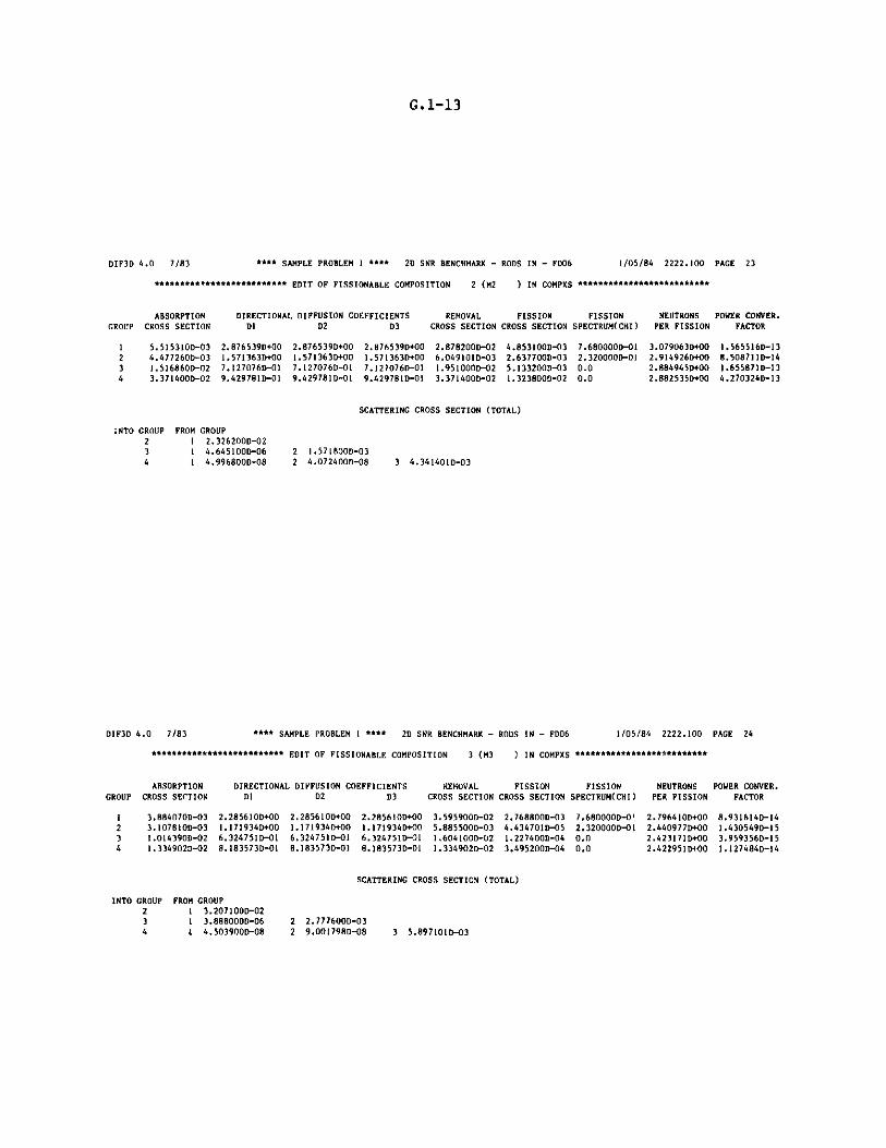
G.1-13
DIF3D 4.0 7/83 **** SAMPLE PROBLEM 1 **** 2D SNR BENCHMARK - RODS IN - FD06 1/05/84 2222.100 PACE 23
************************** EDIT OF FISSIONABLE COMPOSITION 2 (M2 ) IN COMPXS **************************
DIRECTIONAL DIFFUSION COEFFICIENTS REMOVAL FISSIONDI D2 D3 CROSS SECTION CROSS SECTION
2.876539D+00 2.876539D+00 2.876539D+00 2.878200D-02 4.853100D-031.571363D+00 1.5713631)+00 1.571363D+00 6.049101D-03 2.637700D-037.127076D-O1 7.127076D-O1 7.1270760-01 1.951000D-02 5.133200D-039.429781D-O1 9.429781D-Ol 9.4297810-01 3.371400D-02 1.323800D-02
FISSIONSPECTRUM(CHI)
7.680000D-012.320000D-O 10.00.0
NEUTRONS POWER CONVER.PER FISSION FACTOR
3.079063D+00 1.565516D-132.914926D+00 8.508711-142.884945D+00 1.655871D-132.882535D+00 4.270324D-13
SCATTERING CROSS SECTION (TOTAL)
INTO GROUP FROM GROUP2 2.326200D-023 1 4.645100D-064 1 4.996800D-08
2 1.571800D-032 4.072400D-08 3 4.341401D-03
DIF3D 4.0 7/83 **** SAMPLE PROBLEM I **** 2D SNR BENCHMARK - RODS IN - FD06 1/05/84 2222.100 PAGE 24
************************** EDIT OF FISSIONABLE COMPOSITION 3 (M3 ) IN COMPXS ***************** ********
DIRECTIONAL DIFFUSION COEFFICIENTSD1 D2 D3
2.285610D+00 2.285610D+00 2.285610D+001.171934D+00 1.171934D+00 1.171934D+006.324751D-01 6.324751D-01 6.324751D-018.183573D-01 8.183573D-01 8.183573D-01
REMOVAL FISSIONCROSS SECTION CROSS SECTION
3.595900-02 2.768800D-035.885500D-03 4.434701D-051.604100-02 1.227400-041.334902D-02 3.495200-04
FISSION NEUTRONS POWER CONVER.SPECTRUM(CHI) PER FISSION FACTOR
7.680000-0' 2.796410D+00 8.931614D-142.320000-01 2.440977D+00 1.430549D-150.0 2.423171D+00 3.959356D-150.0 2.42295113+00 1.127484D-14
SCATTERING CROSS SECTION (TOTAL)
INTO GROUP FROM GROUP2 1 3.207100D-023 1 3.888000D-06 2 2.7776001-034 4 4.503900-08 2 9.001798D-08 3 5.897101D-03
GROUP
1234
ABSORPTIONCROSS SECTION
5.515310D-034.477260D-031.516860D-023.371400D-02
GROUP
12
3
4
ABSORPTIONCROSS SECTION
3.884070D-033.107810D-031.014390D-021.334902D-02

G.1-14
DIF3D 4.0 7/83 **** SAMPLE PROBLEM 1 **** 2D SNR BENCHMARK - RODS IN - FD06 1/05/84 2222.100 PAGE 25
************************** EDIT OF FISSIONABLE COMPOSITION 4 (M4 ) IN COMPXS **************************
ABSORPTION DIRECTIONAL DIFFUSION COEFFICIENTS REMOVAL FISSION FISSION NEUTRONS POWER CONVER.GROUP CROSS SECTION Dl D2 D3 CROSS SECTION CROSS SECTION SPECTRUM(CHI) PER FISSION FACTOR
1 2.768080D-03 2.716654D+00 2.716654D+00 2.716654D+00 2.909300D-02 1.945300D-03 7.680000D-01 2.790264D+00 6.275163D-14
2 2.201938D-03 1.440943D+00 1.440943D+00 1.440943D+00 4.490900D-03 3.106501D-05 2.3200000-01 2.441880D+00 1.002097D-153 7.7283970-03 7.2034691-01 7.203469D-01 7.2034690-01 1.3082000-02 8.756600D-05 0.0 2.423086D+00 2.8247100-154 9.956190D-03 9.876835D-01 9.8768350-01 9.876835D-O1 9.956190D-03 2.3769000-04 0.0 2.422988D+00 7.667421D-15
SCATTERING CROSS SECTION (TOTAL)
INTO GROUP FROM GROUP2 1 2.632200D-023 1 2.890700D-06 2 2.288900D-034 1 3.3248000-08 2 6.213298D-08 3 5.353600D-03
DIF3O 4.0 7/83 **** SAMPLE PROBLEM 1 **** 20 SNR BENCHMARK - RODS IN - FD06 1/05/84 2222.100 PAGE 26
**************************** EDIT OF NON-FISSIONABLE COMPOSITION 5 (M5 ) IN COMPXS ******************************
ABSORPTION DIRECTIONAL DIFFUSION COEFFICIENTS REMOVAL POWER CONVERSION
GROUP CROSS SECTION Dl D2 D3 CROSS SECTION FACTOR
1 1.866960D-03 2.503066D+00 2.503066D+00 2.503066D+00 2.481400D-02 0.0
2 1.264330D-02 1.314665D+00 1.314665D+00 1.314665D+00 1.641200D-02 0.0
3 6.3440500-02 5.7427700-01 5.7427700-01 5.742770D-01 7.2122000-02 0.0
4 1.6868000-01 6.153695D-01 6.153695D-01 6.153695D-01 1.6868000-01 0.0
SCATTERING CROSS SECTION (TOTAL)
INTO GROUP FROM GROUP2 1 2.294600D-02
3 1 1.032000D-06 2 3.768700D-03
4 1 1.048900D-08 2 7.036100D-12 3 8.681498D-03

G.1-15
DIF3D 4.0 7/83 **** SAMPLE PROBLEM 1 **** 2D SNR BENCHMARK - RODS IN - FD06 1/05/84 2222.100 PAGE 27
**************************** EDIT OF NON-FISSIONABLE COMPOSITION 6 (M6 ) IN COMPXS **** *****************
GROUP
1234
ABSORPTIONCROSS SECTION
2.163050D-041.688000D-041.146800D-037.865999D-04
DIRECTIONAL DIFFUSION COEFFICIENTSD1 D2 D3
4.616420D+00 4.616420D+00 4.616420D+002.901831D+00 2.901831D+00 2.901831D+001.021179D+00 1.021179D+00 1.021179D+001.729625D+00 1.729625D+00 1.729625D+00
REMOVAL POWER CONVERSIONCROSS SECTION FACTOR
1.315900D-02 0.01.455900D-03 0.04.600100D-03 0.07.865999D-04 0.0
SCATTERING CROSS SECTION (TOTAL)
INTO GROUP FROM GROUP2 1 1.294200D-023 1 6.878000D-07 2 1.287100D-034 1 6.990302D-09 2 4.363300D-12 3 3.453300D-03
DIF3D 4.0 7/83 **** SAMPLE PROBLEM 1 **** 2D SNR BENCHMARK - RODS IN - FD06
OUTER ITERATION SUMMARY REAL SOLUTION K-EFF. PROBLEM
OPTIMIZED INNER ITERATION STRATEGYGROUP OPTIMUM NO. OF GROUP OPTIMUM NO. OF GROUP OPTIMUM NO. OFNO. OMEGA INNERS NO. OMEGA INNERS NO. OMEGA INNERS
1 1.42092D+00 7
OUTER REL. POINTIT. NO. ERROR
1 6.055469D-01
2 4.704232D-01
3 1.767146D-01
4 8.690130D-02
5 3.722962D-02
6 1.064050D-02
7 3.829818D-03
8 1.806451D-03
9 4.606560D-04
10 1.203257D-04
11 2.823481D-05
12 1.556538D-05
13 4.066891D-06
14 9.684399D-07
15 2.049522D-07
2 1.57656D+00 11 3 1.27169D+00 5
REL. SUM EIGENVALUEERROR
1.6866930-01
1.306399D-01
7.337978D-02
4.552007D-02
2.073863D-02
6.314254D-03
2.197660D-03
1.012883D-03
2.320342D-04
7.173725D-05
1.472779D-05
1.031790D-05
1.710762D-06
7.739674D-07
1.272518D-07
CHANGE
5.676263D-02
3.391310D-02
1.908419D-02
8.680460D-03
5.107754D-03
2.468417D-03
8.781398D-04
2.399321D-04
9.278793D-05
3.893697D-05
1.050205D-05
2.427902D-06
7.286502D-07
3.097159D-07
8.601389D-08
POLY.
ORDER
0
0
0
2
3
2
3
4
2
3
4
DOM. RATIOUSED
0.0
0.0
0.0
5.957153D-01
5.957153D-01
5.9571530-01
6.280142D-01
6.280142D-01
6.280142D-01
6.280142D-O1
6.331385D-01
6.331385D-01
6.331385D-01
6.331385D-01
6.577679D-01
DOM. RATIOESTIMATED
0.0
8.2699220-01
5.957153D-01
5.957153D-01
6.254009D-01
6.280142D-01
6.280142D-O1
6.305913D-01
6.203958D-01
6.331385D-01
6.3313850-01
7.953652D-Ol
6.304855D-01
6.5776790-01
6.577679D-01
1/05/84 2222.100 PAGE 28
GROUP OPTIMUM NO. OFNO. OMEGA INNERS
4 1.26615D+00 5
K-EFFECTIVE
1.05676263D+00
1.09067574D+00
1.10975993D+00
1.11844039D+00
1.12354814D+00
1.12601656D+00
1.12689470D+00
1.12713463D+00
1.12722742D+00
1.12726635D+00
1.12727686D+00
1.12727928D+00
1.127280010+00
1.12728032D+00
1.12728041D+00
OUTER ITERATIONS COMPLETED AT ITERATION 15, ITERATIONS HAVE CONVERGED
K-EFFECTIVE - 1.12728040833
TO RESTART THIS CALCULATION, INPUT FOLLOWING VALUES
DOMINANCE RATIO (SIGBAR) - 6.577679231397D-01
OPTIMIZED OVER-RELAXATION FACTORSGROUP OPTIMUM GROUP OPTIMUM GROUP OPTIMUM GROUP OPTIMUM GROUP OPTIMUMNO. OMEGA NO. OMEGA NO. OMEGA NO. OMEGA NO. OMEGA1 1.42092D+00 2 1.57656D+00 3 1.27169D+00 4 1.26615D+00
MAXIMUM POWER DENSITY 2.68379D-04 OCCURS AT MESH CELL (I,J,K) - ( 1, 1, 1)
PEAK POWER DENSITY IS CALCULATED BY SAMPLING THE AVERAGE FLUX VALUES ON THE CELL SURFACES AND WITHIN THE CELL.

G.1-16
DIF3D 4.0 7/83 **** SAMPLE PROBLEM I *** 2D SNR BENCHMARK - RODS IN - FD6 1/05/84 2222.200 PAGE 29
REGION AND AREA POWER INTEGRALS FOR K-EFF PROBLEM WITH ENERGY RANGE (EV) -(0.0.1.050D+07)
REGION ZONE ZONE VOLUME INTEGRATION(1) POWER POWER DENSITY PEAK DENSITY PEAK TO AVG. POWERNO. NAME NO. NAME (CC) WEIGHT FACTOR (WATTS) (WATTS/CC) (WATTS/CC)(2) POWER DENSITY FRACTION
I IC I MI 1.430430+03 1.00000D+00 2.86439D-01 2.00247D-04 2.68379D-04 1.34024D+00 5.728780-012 OC 2 M2 1.52096D+03 1.000000+00 2.045460-01 1.34485D-04 2.269940-04 1.68788D+00 4.09092D-OI3 RB 3 M3 1.95552D+03 1.000000+00 9.01489D-03 4.60997D-06 1.81598D-05 3.93925D+00 1.802980-024 CR 5 MS 2.172800+02 1.000000+00 0.0 0.0 0.0 0.0 0.05 CF 6 M6 1.086400+02 1.000000+00 0.0 0.0 0.0 0.0 0.0
TOTALS 5.232830+03 0.0 5.000000-01 9.55506D-05 2.683790-04 2.808760+00 1.00000D+0
AREA AREA VOLUME INTEGRATION(1) POWER POWER DENSITY PEAK DENSITY PEAK TO AVG. POWERNO. NAME (CC) WEIGHT FACTOR (WATTS) (WATTS/CC) (WATTS/CC)(2) POWER DENSITY FRACTION
1 TCORE 2.951390+03 0.0 4.909850-01 1.663570-04 2.68379D-04 1.613270+00 9.819700-012 TROD 3.259200+02 0.0 0.0 0.0 0.0 0.0 0.03 TOTAL 5.232830+03 0.0 5.000000-01 9.555060-05 2.68379D-04 2.808760+00 1.000000+00
(1) INTEGRATION WEIGHT FACTOR - (2/B)*SIN(B*H) H-UNEXTRAPOLATED HALF HEIGHT, B-BUCKLING COEFFICIENT(2) THE PEAK POWER DENSITY IS CALCULATED BY SAMPLING THE AVERAGE FLUX ON THE CELL SURFACES AND WITHIN THE CELL.
REGION ZONE ZONE PEAK INDEX PEAK INDEX PEAK INDEXNO. NAME NO. NAME 'X' 'Y' 'Z'
I IC I Ml 1.000000+00 1.000000+00 1.000000+002 DC 2 M2 1.000000+01 5.000000+00 1.000000+003 RB 3 M3 1.400000+01 7.000000+00 1.000000+004 CR S M5 0.0 0.0 0.0S CF 6 M6 0.0 0.0 0.0
TOTALS 1.000000+00 1.000000+00 1.000000+00
AREA AREA PEAK INDEX PEAK INDEX PEAK INDEXNO. NAME 'X' 'Y' 'Z'
I TCORE 1.000000+00 1.000000+00 1.000000+002 TROD 0.0 0.0 0.03 TOTAL 1.000000+00 1.000000+00 1.000000+00
DIF3D 4.0 7/83 **** SAMPLE PROBLEM I *,* 2D SNR BENCHMARK - RODS IN - F06 1/05/84 2222.200 PAGE 30
REGION AND AREA BALANCE INTEGRALS FOR REAL K-EFF PROBLEM WITH ENERGY RANGE (EV) -(8.000+05,1.050D+07) FOR GROUP 1
REGION ZONE ZONE NET + ABSORPTION + SCATTER - SCATTER - FISSION - EXTERNAL - BALANCENO. NAME NO. NAME LEAKAGE RATE(1) OUT(2) IN PRODUCTION(3) SOURCE
1 IC 1 M1 1.576650+09 2.644070+09 1.35573D+10 0.0 1.777810+10 0.0 -9.777530+022 OC 2 M2 3.270700+09 1.817070+09 7.665430+09 0.0 1.275320+10 0.0 1.637760+033 RB 3 M3 -2.51636D+09 3.280940+08 2.709430+09 0.0 5.211580+08 0.0 1.022780+024 CR 5 M5 -1.286180+09 9.676960+07 1.189410+09 0.0 0.0 0.0 -6.995440-015 CF 6 M6 -5.620520+08 9.238910+06 5.528140+08 0.0 0.0 0.0 -3.63760D+00
TOTALS 4.82764D+08 4.895240+09 2.567440+10 0.0 3.10524D+10 0.0 7.579470+02
AREA AREA NET + ABSORPTION + SCATTER - SCATTER - FISSION - EXTERNAL - BALANCENO. NAME LEAKAGE RATE(1) OUT(2) IN PRODUCTION(3) SOURCE
I TCORE 4.847350+09 4.461140+09 2.122280+10 0.0 3.053130+10 0.0 6.600060+022 TROD -1.848230409 1.060090+08 1.742220+09 0.0 0.0 0.0 -4.337140+003 TOTAL 4.827640+08 4.895240+09 2.567440+10 0.0 3.10524D+10 0.0 7.57947D+02
(1) ABSORPTION - CAPTURE + FISSION(2) SCATTER OUT - TOTAL OUTSCATTER - (N,2N) SOURCE(3) FISSION PRODUCTION - FISSION SOURCE / K-EFF
REGION ZONE ZONE LEAKAGE LEAKAGE LEAKAGE BUCKLING(4) BUCKLING(4) BUCKLING(4) BUCKLING(4)NO. NAME NO. NAME PLANAR Y D*(B**2) TOTAL PLANAR Y Z
I IC 1 M1 1.576650+09 4.069540+08 0.0 9.54084D-04 9.54084D-04 2.462610-04 0.02 DC 2 M2 3.27070Q+09 8.038410+08 0.0 3.45119D-03 3.451190-03 8.48200D-04 0.03 RB 3 M3 -2.516360+09 -4.820040+08 0.0 -1.30334D-02 -1.303340-02 -2.496530-03 0.04 CR 5 MS -1.286180+09 -4.48257D+08 0.0 -9.913440-03 -9.913440-03 -3.455020-03 0.05 CF 6 M6 -5.620520+08 -1.774140+08 0.0 -2.85048D-03 -2.850480-03 -8.997620-04 0.0
TOTALS 4.827640+08 1.031210+08 0.0 1.547210-04 1.54721D-04 3.304930-05 0.0
AREA AREA LEAKAGE LEAKAGE LEAKAGE BUCKLING(4) BUCKLING(4) BUCKLING(4) BUCKLING(4)NO. NAME PLANAR Y D*(B**2) TOTAL PLANAR Y Z
1 TCORE 4.847350+09 1.210800+09 0.0 1.86420D-03 1.86420D-03 4.656490-04 0.02 TROD -1.848230+09 -6.256700+08 0.0 -5.653480-03 -5.653480D-03 -1.913840-03 0.03 TOTAL 4.82764D+08 1.03121D+08 0.0 1.54721D-04 1.54721D-04 3.30493D-05 0.0
(4) BUCKLING " B**2 " LEAKAGE / (D*FLUX*VOLUME) 1/CM**2

G.1-17
DIF3D 4.0 7/83 **** SAMPLE PROBLEM 1 **** 2D SNR BENCHMARK - RODS IN - FD06 1/05/84 2222.300 PAGE 31
REGION AND AREA BALANCE INTEGRALS FOR REAL K-EFF PROBLEM WITH ENERGY RANGE (EV) -(8.000D+05,1.050D+07) FOR GROUP 1
REGION ZONE ZONENO. NAME NO. NAME
1 IC 1 M12 OC 2 M23 RB 3 M34 CR 5 M55 CF 6 M6
TOTALS
AREANO.
123
AREANAME
TCORETRODTOTAL
CAPTURERATE
3.96700D+082.18171D+089.42088D+079.67696D+079.23891D+068.15089D+08
CAPTURERATE
6.14871D+081.06009D+088.15089D+08
FISSIONRATE
2.24737D+091.59890D+092.33885D+080.00.04.08015D+09
FISSIONRATE
3.84627D+090.04.08015D+09
DIF3D 4.0 7/83 **** SAMPLE PROBLEM 1 **** 2D SNR BENCHMARK - RODS IN - FD06 1/05/84 2222.300 PAGE 32
REGION AND AREA BALANCE INTEGRALS FOR REAL K-EFF PROBLEM WITH ENERGY RANGE (EV) -(1.000D+04,8.000D+05) FOR GROUP 2
REGIONNO. NAME
1 IC2 0C3 RB4 CR5 CF
TOTALS
ZONE ZONENO. NAME
1 MI2 M23 M35 MS6 M6
NET +LEAKAGE
3.74742D+092.62129D+09
-7.60597D+08-2.71777D+092.12795D+083.10313D+09
ABSORPTION +RATE(1)
1.05298D+106.58375D+091.91529D+093.00993D+093.94190D+072.20782D+10
AREA AREA NET + ABSORPTION +NO. NAME LEAKAGE RATE(1)
1 TCORE 6.36871D+09 1.71136D+102 TROD -2.50498D+09 3.04935D+093 TOTAL 3.10313D+09 2.20782D+10
(1) ABSORPTION - CAPTURE + FISSION(2) SCATTER OUT - TOTAL OUTSCATTER - (N,2N) SOURCE(3) FISSION PRODUCTION - FISSION SOURCE / K-EFF
REGION ZONE ZONENO. NAME NO. NAME
1 IC 1 Mi2 OC 2 M23 RB 3 M34 CR 5 MS5 CF 6 M6
TOTALS
AREANO.
123
AREANAME
TCORETRODTOTAL
LEAKAGEPLANAR
3.74742D+092.62129D+09
-7.60597D+08-2.71777D+09
2.12795D+083.10313D+09
LEAKAGEPLANAR
6.36871D+09-2.50498D+09
3.10313D+09
LEAKAGEY
8.49477D+085.90552D+082.79571D+07
-8.74492D+088.81135D+076.81608D+08
LEAKAGEY
1.44003D+09-7.86378D+08
6.81608D+08
SCATTER - SCATTER -OUT(2) IN
4.64816D+09 1.35550D+102.31137D+09 7.66388D+091.71184D+09 2.70909D+098.97197D+08 1.18935D+093.00570D+08 5.52784D+089.86914D+09 2.56701D+10
SCATTER - SCATTER -OUT(2) IN
6.95954D+09 2.12189D+101.19777D+09 1.74214D+099.86914D+09 2.56701D+10
LEAKAGE BUCKLING(4)D*(B**2) TOTAL
0.0 8.29053D-040.0 1.13443D-030.0 -1.05311D-030.0 -8.68365D-030.0 3.14020D-040.0 3.63209D-04
LEAKAGE BUCKLING(4)D*(B**2) TOTAL
0.0 9.32353D-040.0 -2.52868D-030.0 3.63209D-04
FISSION - EXTERNAL - BALANCEPRODUCTION(3) SOURCE
5.37046D+09 0.0 -4.34370D+023.85253D+09 0.0 4.53192D+021.57433D+08 0.0 2.75525D+010.0 0.0 -3.16520D+000.0 0.0 -1.69340D+019.38042D+09 0.0 2.62747D+01
FISSION - EXTERNAL - BALANCEPRODUCTION( 3) SOURCE
9.22298D+09 0.0 1.88213D+010.0 0.0 -2.00992D+019.38042D+09 0.0 2.62747D+01
BUCKLING(4)PLANAR
8.29053D-041.13443D-03
-1.05311D-03-8.68365D-033.14020D-043.63209D-04
BUCKLING(4)PLANAR
9.32353D-04-2.52868D-03
3.63209D-04
BUCKLING(4) BUCKLING(4)Y Z
1.87932D-04 0.02.55576D-04 0.03.87088D-05 0.0
-2.79412D-03 0.01.30028D-04 0.07.97793D-05 0.0
BUCKLING(4) BUCKLING(4)Y Z
2.10814D-04 0.0-7.93820D-04 0.0
7.97793D-05 0.0
(4) DUCKLING - a**2 - LEAKAGE / (D*FLUX*VOLUME) 1/CM**2

G.1-18
DIF3D 4.0 7/83 **** SAMPLE PROBLEM 1 **** 2D SNR BENCHMARK - RODS IN - FD06 1/05/84 2222.300 PAGE 33
REGION AND AREA BALANCE INTEGRALS FOR REAL K-EFF PROBLEM WITH ENERGY RANGE (EV) -(1.000D+04,8.000D+05) FOR GROUP 2
REGIONNO. NAME
1 IC2 0C3 RB4 CR5 CF
TOTALS
AREANO.
123
ZONE ZONENO. NAME
1 M12 M23 M35 M56 M6
AREANAME
TCORETRODTOTAL
CAPTURERATE
5.26803D+092.70505D+091.88795D+093.00993D+093.94190D+071.29104D+10
CAPTURERATE
7.97308D+093.04935D+091.29104D+10
FISSIONRATE
5.26182D+093.87870D+092.73302D+070.00.09.16785D+09
FISSIONRATE
9.14052D+090.09.16785D+09
DIF3D 4.0 7/R3 **** SAMPLE PROBLEM 1 **** 2D SNR BENCHMARK - RODS IN - FD06 1/05/84 2222.300 PAGE 34
REGION AND AREA BALANCE INTEGRALS FOR REAL K-EFF PROBLEM WITH ENERGY RANGE (EV) -(1.000D+03,1.000D+04) FOR GROUP 3
REGIONNO. NAME
1 IC2 0C3 RB4 CR5 CF
TOTALS
AREANO.
123
(1)(2)(3)
ZONE ZONENO. NAME
1 M12 M23 M35 M56 M6
NET +LEAKAGE
6.45877D+07-6.58282D+073.63142D+08
-2.41728D+081.84679D+083.04852D+08
ABSORPTION +RATE( 1)
3.36623D+091.84936D+098.53052D+081.00188D+092.88988D+077.09943D+09
AREA NET + ABSORPTION +NAME LEAKAGE RATE( 1)
TCORE -1.24053D+06 5.21560D+09TROD -5.70492D+07 1.03078D+09TOTAL 3.04852D+08 7.09943D+09
ABSORPTION - CAPTURE + FISSIONSCATTER OUT - TOTAL OUTSCATTER - (N,2N) SOURCE
FISSION PRODUCTION - FISSION SOURCE / K-EFF
REGION ZONE ZONENO. NAME NO. NAME
1 IC 1 Ml2 OC 2 M23 RB 3 M34 CR 5 MS5 CF 6 M6
TOTALS
AREANAME
TCORETRODTOTAL
LEAKAGEPLANAR
6.45877D+07-6.58282D+073.63142D+08
-2.41728D+081.84679D+083.04852D+08
LEAKAGEPLANAR
-1.24053D+06
-5.70492D+073.04852D+08
LEAKAGEY
-1.34218D+06-7.24701D+069.08582D+07
-7.65302D+076.19366D+076.76754D+07
LEAKAGEY
-8.58919D+06-1.45936D+076.76754D+07
SCATTER -OUT(2)
1.21956D+095.29306D+084.95917D+081.37102D+088.702150+072.46891D+09
SCATTER -OUT(2)
1.74887D+092.24123D+082.46891D+09
LEAKAGED*(B**2)
0.00.00.00.00.00.0
LEAKAGED*(B**2)
0.00.00.0
SCATTER -IN
4.65039D+09
2.31284D+091.71211D+098.97250D+083.00599D+089.87319D+09
SCATTER -IN
6.96323D+091.19785D+099.87319D+09
BUCKLING(4)TOTAL
3.43332D-04-7.57571D-046.82751D-03
-2.66537D-027.17668D-038.39803D-04
BUCKLING(4)TOTAL
-4.51077D-06-1.63923D-03
8.39803D-04
FISSION -PRODUCTION(3)
0.00.00.00.00.00.0
FISSION -PRODUCTION(3)
0.00.00.0
BUCKLING(4)PLANAR
3.43332D-04-7.57571D-046.82751D-03
-2.66537D-027.17668D-038.39803D-04
BUCKLING(4)PLANAR
-4.51077D-06-1.63923D-03
8.39803D-04
EXTERNAL - BALANCESOURCE
0.0 -7.18331D+010.0 9.56224D+000.0 1.71880D+000.0 6.93582D-010.0 -6.75876D+000.0 -6.66173D+01
EXTERNAL - BALANCESOURCE
0.0 -6.22709D+010.0 -6.06518D+000.0 -6.66173D+01
BUCKLING(4) BUCKLING(4)Y Z
-7.13467D-06 0.0-8.34009D-05 0.01.70824D-03 0.0
-8.43847D-03 0.02.40687D-03 0.01.86431D-04 0.0
BUCKLING(4) BUCKLING(4)Y Z
-3.12318D-05 0.0-4.19328D-04 0.0
1.86431D-04 0.0
(4) BUCKLING - B**2 - LEAKAGE / (D*FLUX*VOLUME) 1/CM**2
AREANO.
23

G.1-19
DIF3D 4.0 7/83 **** SAMPLE PROBLEM 1 **** 2D SNR BENCHMARK - RODS IN - FD06 1/05/84 2222.300 PAGE 35
REGION AND AREA BALANCE INTEGRALS FOR REAL K-EFF PROBLEM WITH ENERGY RANGE (EV) -(1.000D+03,1.000D+04) FOR GROUP 3
REGION ZONE ZONE CAPTURE FISSIONNO. NAME NO. JAME RATE RATE
1 IC 1 M1 2.42017D+09 9.46062D+082 OC 2 M2 1.22352D+09 6.25843D+083 RB 3 M3 8.42730D+08 1.03218D+074 CR 5 M5 1.00188D+09 0.05 CF 6 M6 2.88988D+07 0.0
TOTALS 5.51720D+09 1.58223D+09
AREA AREA CAPTURE FISSIONNO. NAME RATE RATE
1 TCORE 3.64369D+09 1.57190D+092 TROD 1.03078D+09 0.03 TOTAL 5.51720D+09 1.58223D+09
DIF3D 4.0 7/83 **** SAMPLE PROBLEM I **** 2D SNR BENCHMARK - RODS IN - FD06 1/05/84 2222.300 PAGE 36
REGION AND AREA BALANCE INTEGRALS FOR REAL K-EFF PROBLEM WITH ENERGY RANGE (EV) -(0.0 ,1.000D+03) FOR GROUP 4
REGION ZONE ZONE NET + ABSORPTION + SCATTER - SCATTER - FISSION - EXTERNAL - BALANCENO. NAME NO. NAME LEAKAGE RATE(1) OUT(2) IN PRODUCTION(3) SOURCE
1 IC I M1 7.11501D+05 1.219000+09 0.0 1.21971D+09 0.0 0.0 -1.95035D+012 OC 2 M2 -7.54205D+07 6.04803D+08 0.0 5.29383D+08 0.0 0.0 3.47536D+003 RB 3 M3 1.93332D+08 3.02644D+08 0.0 4.95977D+08 0.0 0.0 2.38160D+004 CR 5 M5 -8.69602D+07 2.24062D+08 0.0 1.37102D+08 0.0 0.0 1.01616D-015 CF 6 M6 8.29646D+07 4.05718D+06 0.0 8.70218D+07 0.0 0.0 -2.94183D+00
TOTALS 1.14628D+08 2.35457D+09 0.0 2.46919D+09 0.0 0.0 -1.64868D+01
AREA AREA NET + ABSORPTION + SCATTER - SCATTER - FISSION - EXTERNAL - BALANCENO. NAME LEAKAGE RATE(1) OUT(2) IN PRODUCTION(3) SOURCE
1 TCORE -7.47090D+07 1.82380D+09 0.0 1.74909D+09 0.0 0.0 -1.60282D+012 TROD -3.99564D+06 2.28120D+08 0.0 2.24124D+08 0.0 0.0 -2.84021D+003 TOTAL 1.14628D+08 2.35457D+09 0.0 2.46919D+09 0.0 0.0 -1.64868D+01
(1) ABSORPTION - CAPTURE + FISSION(2) SCATTER OUT - TOTAL OUTSCATTER - (N,2N) SOURCE(3) FISSION PRODUCTION - FISSION SOURCE / K-EFF
REGION ZONE ZONE LEAKAGE LEAKAGE LEAKAGE BUCKLING(4) BUCKLING(4) BUCKLING(4) BUCKLING(4)NO. NAME NO. NAME PLANAR Y D*(B**2) TOTAL PLANAR Y Z
1 IC 1 M1 7.11501D+05 -6.94211D+06 0.0 1.60699D-05 1.60699D-05 -1.56794D-04 0.02 OC 2 M2 -7.54205D+07 -1.26134D+07 0.0 -4.45845D-03 -4.45845D-03 -7.45634D-04 0.03 RB 3 M3 1.93332D+08 4.50569D+07 0.0 1.04203D-02 1.04203D-02 2.42849D-03 0.04 CR 5 M5 -8.69602D+07 -2.72170D+07 0.0 -1.063850-01 -1.06385D-01 -3.32965D-02 0.05 CF 6 M6 8.296460+07 2.76208D+07 0.0 9.29974D-03 9.29974D-03 3.09609D-03 0.0
TOTALS 1.14628D+08 2.59053D+07 0.0 1.28099D-03 1.28099D-03 2.89496D-04 0.0
AREA AREA LEAKAGE LEAKAGE LEAKAGE BUCKLING(4) BUCKLING(4) BUCKLING(4) BUCKLING(4)NO. NAME PLANAR Y D*(B**2) TOTAL PLANAR Y Z
1 TCORE -7.47090D+07 -1.95555D+07 0.0 -1.220900-03 -1.220900-03 -3.19577)-04 0.02 TROD -3.99564D+06 4.03804D+05 0.0 -4.102900-04 -4.10290D-04 4.14643D-05 0.03 TOTAL 1.14628D+08 2.59053D+07 0.0 1.28099D-03 1.28099D-03 2.89496D-04 0.0
(4) BUCKLING - B**2 - LEAKAGE / (D*FLUX*VOLUME) 1/CM**2

G.1-20
DIF3D 4.0 7/83 **** SAMPLE PROBLEM 1 **** 2D SNR BENCHMARK - RODS IN - FD06 1/05/84 2222.300 PAGE 37
REGION AND AREA BALANCE INTEGRALS FOR REAL K-EFF PROBLEM WITH ENERGY RANGE (EV) -(0.0,1.000D+03) FOR GROUP 4
REGION ZONE ZONENO. NAME NO. NAME
1 IC 1 M12 OC 2 M23 RB 3 M34 CR 5 M55 CF 6 M6
TOTALS
AREA AREANO. NAME
1 TCORE2 TROD3 TOTAL
CAPTURE FISSIONRATE RATE
7.94636D+08 4.24364D+083.67324D+08 2.37479D+082.94720D+08 7.92419D+062.24062D+08 0.04.05718D+06 0.01.68480D+09 6.69768D+08
CAPTURE FISSIONRATE RATE
1.16196D+0; 6.61844D+082.28120D+08 0.01.68480D+09 6.69768D+08
DIF3D 4.0 7/83 **** SAMPLE PROBLEM 1 **** 2D SNR BENCHMARK - RODS IN - FD06
REGION AND AREA BALANCE INTEGRALS FOR REAL K-EFF PROBLEM WITH ENERGY RANGE (EV) -(0.0
1/05/84 2222.300 PAGE 38
,1.050D+07)
REGION ZONE ZONENO. NAME NO. NAME
1 IC 1 Ml2 OC 2 M23 RB 3 M34 CR 5 M55 CF 6 M6
TOTALS
AREA AREANO. NAME
NET + ABSORPTION + SCATTER - SCATTER - FISSION - EXTERNAL - BALANCELEAKAGE RATE(1) OUT(2) IN PRODUCTION(3) SOURCE
5.38937D+09 1.77591D+10 1.94251D+10 1.94251D+10 2.31485D+10 0.0 -1.50346D+035.75074D+09 1.08550D+10 1.05061D+10 1.05061D+10 1.66057D+10 0.0 2.10399D+03
-2.72048D+09 3.39908D+09 4.91718D+09 4.91718D+09 6.78592D+08 0.0 1.33931D+02-4.33264D+09 4.33264D+09 2.22371D+09 2.22371D+09 0.0 0.0 -3.06955D+00-8.16137D+07 8.16139D+07 9.40405D+08 9.40405D+08 0.0 0.0 -3.02721D+014.00538D+09 3.64275D+10 3.80125D+10 3.80125D+10 4.04328D+10 0.0 7.01118D+02
NET + ABSORPTION + SCATTER - SCATTER - FISSION - EXTERNAL - BALANCELEAKAGE RATE(1) OUT(2) IN PRODUCTION(3) SOURCE
1 TCORE 1.11401D+10 2.86141D+102 TROD -4.41425D+09 4.41425D+093 TOTAL 4.00538D+09 3.64275D+10
(1) ABSORPTION - CAPTURE + FISSION(2) SCATTER OUT - TOTAL OUTSCATTER - (N,2N) SOURCE(3) FISSION PRODUCTION - FISSION SOURCE / K-EFF
REGION ZONE ZONE LEAKAGE LEAKAGENO. NAME NO. NAME PLANAR Y
1 IC 1 M1 5.38937D+09 1.24815D+092 OC 2 M2 5.75074D+09 1.37453D+093 RB 3 M3 -2.72048D+09 -3.18132D+084 CR 5 MS -4.33264D+09 -1.42650D+095 CF 6 M6 -8.16137D+07 2.57230D+05
2.82831D-07 0.0TOTALS 4.00538D+09 8.78309D+08
AREA AREA LEAKAGE LEAKAGENO. NAME PLANAR Y
1 TCORE 1.11401D+10 2.62268D+092 TROD -4.41425D+09 -1.42624D+093 TOTAL 4.00538D+09 8.78309D+08
2.99312D+10 2.99312D+10 3.97542D+10 0.03.16411D+09 3.16411D+09 0.0 0.03.80125D+10 3.80125D+10 4.04328D+10 0.0
(N,2N) SOURCE - SCATTER IN - SCATTER OUT
LEAKAGED*(B**2)
0.00.00.00.00.0
0.0
6.00528D+02-3.33417D+017.01118D+02
BUCKLING(4) BUCKLING(4) BUCKLING(4) BUCKLING(4)TOTAL PLANAR Y Z
8.41426D-04 8.41426D-04 1.94869D-04 0.01.71042D-03 1.71042D-03 4.088210-04 0.0
-2.75617D-03 -2.75617D-03 -3.22305D-04 0.0-9.57270D-03 -9.572700-03 -3.15176D-03 0.0-8.97364D-05 -8.97364D-05
3.30576D-04 3.30576D-04 7.24895D-05 0.0
LEAKAGE BUCKLING(4) BUCKLING(4) BUCKLING(4) BUCKLING(4)D*(B**2) TOTAL PLANAR Y Z
0.0 1.14056D-03 1.14056D-03 2.68518D-04 0.00.0 -3.24080D-03 -3.24080D-03 -1.04710D-03 0.00.0 2.30576D-04 3.30576D-04 7.24895D-05 0.0
(4) BUCKLING - B**2 - LEAKAGE / (D*FLUX*VOLUME) 1/CM**2

G.1-21
DIF3D 4.0 7/83 **** SAMPLE PROBLEM 1 **** 2D SNR BENCHMARK - RODS IN - FD06 1/05/84 2222.300 PAGE 39
REGION AND AREA BALANCE INTEGRALS FOR REAL K-EFF PROBLEM WITH ENERGY RANGE (EV) -(0.0 ,1.050D+07)
REGION ZONE ZONE CAPTURE FISSION (N2,N) NET MEDIAN ENERGY MEDIAN ENERGY MEDIAN ENERGYNO. NAME NO. NAME RATE RATE SOURCE PRODUCTION(5) FISSION SRC. ABSORPTN RATE FLUX
1 IC 1 M 8.87953D+09 8.87961D+09 4.58523D+03 2.314850+10 1.96454D+06 5.97212D+04 1.09702D+052 OC 2 M2 4.514070+09 6.34093D+09 1.93424D+03 1.66057D+10 1.96454D+06 7.235450+04 1.186410+053 RB 3 M3 3.119610+09 2.79462D+08 3.30957D+02 6.785920+08 1.964540+06 3.47039D+04 8.26269D+044 CR 5 MS 4.33264D+09 0.0 1.64067D+02 1.64067D+02 0.0 3.93165D+04 1.231090+055 CF 6 M6 8.16139D+07 0.0 2.40705D+02 2.40705D+02 0.0 2.39350D+04 1.00436D+05
TOTALS 2.09275D+10 1.55000D+10 7.25520D+03 4.04328D+10 1.96454D+06 5.689420+04 1.08645D+05
AREA AREA CAPTURE FISSION (N2,N) NET MEDIAN ENERGY MEDIAN ENERGY MEDIAN ENERGYNO. NAME RATE RATE SOURCE PRODUCTIONS) FISSION SRC.
ABSORPTN RATE FLUX
1 TCORE 1.33936D+10 1.52205D+10 6.51947D+03 3.97542D+10 1.96454D+06 6.429680+04 1.12647D+052 TROD 4.41425D+09 0.0 4.04772D+02 4.047720+02 0.0 3.90651D+04 1.113050+053 TOTAL 2.09275D+10 1.55000D+10 7.25520D+03 4.04328D+10 1.96454D+06 5.68942D+04 1.08645D+05
(5) NET PRODUCTION - FISSION PRODUCTION + (N,2N) SOURCE
DIF3D 4.0 7/83 **** SAMPLE PROBLEM 1 **** 2D SNR BENCHMARK - RODS kN - FD06 1/05/84 2222.300 PAGE 40
BALANCE INTEGRAL TOTALS BY GROUP FOR REAL K-EFF PROBLEM WITH ENERGY RANGE (EV) -(0.0 ,1.050D+07)
GROUP EMIN EMAX NET + ABSORPTION + SCATTER - SCATTER - FISSION - EXTERNAL - BALANCENO. (EV) (EV) LEAKAGE RATE(l) OUT(2) IN PRODUCTION(3) SOURCE
1 8.OOD+05 1.050+07 4.827640+08 4.895240+09 2.56744D+10 0.0 3.10524D+10 0.0 7.579470+022 1.OOD+04 8.00D+05 3.10313D+09 2.20782D+10 9.869140+09 2.567010+10 9.380420+09
0.0 2.627470+013 1.000+03 1.000+04 3.048520+08 7.099430+09 2.46891D+09 9.87319D+09 0.0 0.0 -6.661730+014 0.0 1.OOD+03 1.146280+08 2.35457+09 0.0 2.469190+09 0.0 0.0 -1.64868D+01TOTALS 4.005380+09 3.64275D+10 3.80125D+10 3.80125D+10 4.04328D+10 0.0 7.011180+02
(1) ABSORPTION - CAPTURE + FISSION(2) SCATTER OUT - TOTAL OUTSCATTER - (N,2N) SOURCE(3) FISSION PRODUCTION - FISSION SOURCE / K-EFF
GROUP EMIN EMAX LEAKAGE LEAKAGE LEAKAGE BUCKL.ING(4) BUCKLING(4) BUCKLING(4) BUCKLING(4)NO. (EV) (EV) PLANAR Y D*(B**2) TOTAL PLANAR Y Z
1 8.000+05 1.05D+07 4.827640+08 1.031210+08 0.0 1.54721D-04 1.54721D-04 3.30493D-05 0.02 1.000+04 8.00D+05 3.103130+09 6.816080+08 0.0 3.63209D-04 3.632090-04 7.97793D-05 0.03 1.000+03 1.000+04 3.048520+08 6.76754D+07 0.0 8.39803D-04 8.39803D-04 1.864310-04 0.04 0.0 1.000+03 1.146280+08 2.590530+07 0.0 1.280990-03 1.280990-03 2.8946D-04 0.0
TOTALS 4.00538D+09 8.783090+08 0.0 3.305760-04 3.30576D-04 7.248950-05 0.0
(4) BUCKLING - B**2 - LEAKAGE / (D*FLUX*VOLUME) 1/CM**2
GROUP EMIN EMAX CAPTURE FISSIONNO. (EV) (EV) RATE RATE
1 8.00+05 1.05D+07 8.150890+08 4.080150+092 1.00D+04 8.00D+05 1.291040+10 9.167850+093 1.00D+03 1.000+04 5.517200+09 1.582230+094 0.0 1.000+03 1.684800+09 6.697680+08
TOTALS 2.092750+10 1.550000+10

G.1-22
DIF3D 4.0 7/83 **** SAMPLE PROBLEM 1 **** 2D SNR BENCHMARK - RODS IN - FD06
REGION AND AREA REAL FLUX INTEGRALS FOR K-EFF PROBLEM WITH ENERGY RANGE (EV) -(0.0
1/05/84 2222.300 PAGE 41
,1.050D+07)
REGION ZONE ZONENO. NAME NO. NAME
1 IC 1 M12 OC 2 M23 RB 3 M34 CR 5 M55 CF 6 M6
TOTALS
VOLUME(CC)
1.43043D+031.52096D+031.95552D+032.17280D+021.08640D+025.23283D+03
AREA AREA VOLUMENO. NAME (CC)
1 TCORE 2.95139D+032 TROD 3.25920D+023 TOTAL 5.23283D+03
(1) PEAK FLUX CALCULATIONS ARE COMPUTED BY
REGION ZONE ZONENO. NAME NO. NAME
1 IC 1 Ml2 OC 2 M23 RB 3 M34 CR 5 MS5 CF 6 M6
TOTALS
AREANO.
123
AREANAME
TCOFETRODTOTAL
GROUP
5.74436D+113.29459D+118.44717D+105.183270+104.271240+101.082910+12
GROUP
9.03896D+119.454510+101.08291D+12
TOTAL FLUX(NEUTRON-CM/SEC)
3.75825D+121.93981D+128.07520D+113.07019D+113.06595D+117.11919D+12
TOTAL FLUX(NEUTRON-CM/SEC)
5.69805D+126.13613D+117.11919D+12
SAMPLING AVERAGE
GROUP2
2.87751D+121.47049D+126.16281D+112.38065D+112.33525D+115.43587D+12
GROUP2
4.34800D+124.71590D+115.43587D+12
PEAK FLUX (1) TOTAL FAST FLUX PEAK FAST FLUX(1)(NEUTRON/CM2-SEC)(NEUTRON-CM/SEC) (NEUTRON/CM2-SEC)
3.52624D+09 1.93993D+12 1.82299D+092.149260+09 1.027260+12 1.125980+091.200600+09 3.76921D+11 6.144090+081.72130D+09 1.64804D+11 9.09090D+082.96550D+09 1.53529D+11 1.49456D+093.526240+09 3.66244D+12 1.82299D+09
PEAK FLUX (1) TOTAL FAST FLUX PEAK FAST FLUX(1)(NEUTRON/CM2-SEC)(NEUTRON-CM/SEC) (NEUTRON/CM2-SEC)
3.52624D+09 2.967190+12 1.82299D+092.965500+09 3.183330+11 1.49456D+093.526240+09 3.662440+12 1.a2299D+09
FLUXES ON THE SURFACE AND WITHIN EACH MESH CELL.
GROUP3
2.60379D+111.21921D+118.40951D+101.57924D+102.51995D+105.07387D+11
GROUP3
3.82300D+114.09919D+105.07387D+11
GROUP4
4.59194D+101.79392D+102.26716D+101.32833D+095.15786D+099.30165D+10
GROUP4
6.38586D+106.48619D+099.30165D+10
DIF3D 4.0 7/83
ZONE ZONENO. NAME
1 M12 M23 M34 M45 M56 M6
TOTALS
**** SAMPLE PROBLEM 1 **** 2D SNR BENCHMARK - RODS IN - FD06
REAL ZONE FLUX AVERAGES FOR K-EFF PROBLEM WITH ENERGY RANGE (EV) -(0.0
VOLUME(CC)
1.430430+031.52096D+031.955520+030.02.172800+021.086400+025.232830+03
AVG. TOTAL FLUX(NEUTRON/CM2-SEC)
2.62736D+091.27538D+094.12944D+080.01.41301D+092.82211D+091.36049D+09
GROUP1
4.01584D+082.16613D+084.31965D+070.02.38553D+083.93155D+082.06946D+08
GROUP2
2.01164D+099.66815D+083.15149D+080.01.09566D+092.14953D+091.03880D+09
1/05/84 2222.300 PAGE 42
,1.050D+07)
GROUP3
1.82029D+088.01603D+074.30039D+070.07.26822D+072.31954D+089.696220+07
GROUP4
3.21019D+071.17947D+071.15937D+070.06.113440+064.74766D+071.777560+07

G.1-23
DIF3D 4.0 7/83 **** SAMPLE PROBLEM 1 **** 2D SNR BENCHMARK - RODS IN - FD06
*** THE FOLLOWING BINARY FILES HAVE BEEN WRITTEN ***
FILE NAME VERSION NO. LOGICAL UNIT
RTFLUXDIF3D
1/05/84 2222.300 PAGE 43
3018
BPOINTER SPACE USED, FCM - 409 ECM - 5992 WORDS
COMPUTING TIME SUMMARY CENTRAL PROCESSOR (SEC)
BINARY FILE INPUT PROCESSING
INITIALIZATION AND INPUT EDITTINGSTEADY STATE REAL FLUX CALCULATIONEDIT REAL CALCULATION OUTPUTSTEADY STATE ADJOINT FLUX CALCULATIONEDIT ADJOINT CALCULATION OUTPUTNODAL MATHEMATICAL-ADJOINT CALCULATIONTOTAL FOR THIS STEP
TOTAL ELAPSED COMPUTING TIME (SEC)
0.100.201.550.770.00.00.02.65
4.89
PERIPHERAL PROCESSOR (SEC)
0.00.00.00.00.00.00.00.0
0.0 - 4.89
11
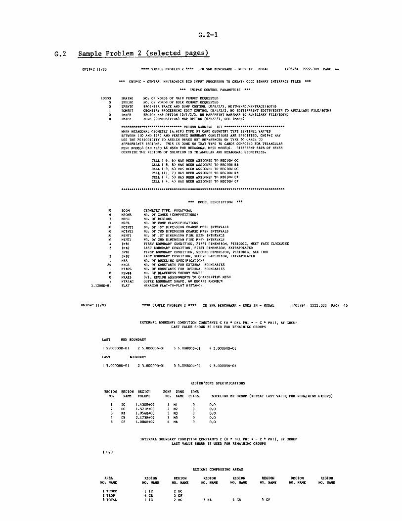
G.2-1
G.2 Sample Problem 2 (selected pages)
GNIP4C 11/83 **** SAMPLE PROBLEM 2 **** 2D SNR BENCHMARK - RODS IN - NODAL 1/05/84 2222.300 PAGE 44
++ CNIP4C - GENERAL NEUTRONICS BCD INPUT PROCESSOR TO CREATE CCCC BINARY INTERFACE FILES ***
*** GNIP4C CONTROL PARAMETERS ***
10000 IMAING NO. OF WORDS OF MAIN MEMORY REQUESTED0 IBULKG NO. OF WORDS OF BULK MEMORY REQUESTED0 IPRNTG BPOINTER TRACE AND DUMP CONTROL (0/1/2/3, NEITHER/DUMP/TRACE/BOTH)
I IGMEDT GEOMETRY PROCESSING EDIT CONTROL (0/1/2/3, NO EDITS/PRINT EDITS/EDITS TO AUXILIARY FILE/BOTH)0 IMAPR REGION MAP OPTION (0/1/2/3, NO MAP/PRINT MAP/MAP TO AUXILIARY FILE/BOTH)0 IMAPZ ZONE (COMPOSITION) MAP OPTION (0/1/2/3, SEE IMAPR)
********************i**#*A* ** TRIGOM WARNING 163 ******************#**********
WHEN HEXAGONAL GEOMETRY (A.NIP3 TYPE 03 CARD GEOMETRY TYPE SENTINEL VAlESBETWEEN 110 AND 128) AND PERIODIC BOUNDARY CONDITIONS ARE SPECIFIED, GNIP4C MAY
USE THE PERIODICITY TO ASSIGN HEXES NOT REFERENCED ON TYPE 30 CARDS TOAPPROPRIATE REGIONS. THIS IS DONE SO THAT TYPE 30 CARDS COMPOSED FOR TRIANGULARMESH MODELS CAN ALSO BE USED FOR HEXAGONAL MESH MODELS. DIFFERENT SETS OF HEXESCOMPRISE THE REGIONS OF SOLUTION IN TRIANGULAR AND HEXAGONAL GEOMETRIES.
CELL ( 6, 6) HAS BEEN ASSIGNED TO REGION OC
CELL ( 8, 8) HAS BEEN ASSIGNED TO REGION RBCELL ( 9, 6) HAS BEEN ASSIGNED TO REGION OC
CELL (II, 7) HAS BEEN ASSIGNED TO REGION RBCELL ( 7, 5) HAS BEEN ASSIGNED TO REGION CRCELL ( 4, 4) HAS BEEN ASSIGNED TO REGION CF
** MODEL DESCRIPTION ***
10 IGOM GEOMETRY TYPE, HEXAGONAL6 NONE NO. OF ZONES (COMPOSITIONS)
5 NREG NO. OF REGIONSI NZCL NO. OF ZONE CLASSIFICATIONS
10 NCINTI NO. OF 1ST DIMENSION COARSE MESH INTERVALS
10 NCINTJ NO. OF ?ND DIMENSION COARSE MESH INTERVALS10 NINTI NO. OF 1ST DIMENSION FINE MESH INTERVALS
10 NINTJ NO. O 2ND DIMENSION FINE MESH INTERVALS4 IMBI FIRST BOUNDARY CONDITION, FIRST DIMENSION, PERIODIC, NEXT FACE CLOCKWISE2 IMB2 LAST BOUNDARY CONDITION, FIRST DIMENSION, EXTRAPOLATED
JMBI FIRST BOUNDARY CONDITION, SECOND DIMENSION, PERIODIC, SEE IMBI
2 JMB2 LAST BOUNDARY CONDITION, SECOND DIMENSION, EXTRAPOLATED
I NBS NO. OF BUCKLING SPECIFICATIONS24 NBCS NO. OF CONSTANTS FOR EXTERNAL BOUNDARIES
I NIBCS NO. OF CONSTANTS FOR INTERNAL BOUNDARIES0 NZWBB NO. OF BLACKNESS THEORY ZONES
0 NRASS 0/1, REGION ASSIGNMENTS TO COARSE/FINE MESHI NTRIAG OUTER BOUNDARY SHAPE, 60 DEGREE RHOMBUS
1.1200D+01 FLAT HEXAGON FLAT-TO-FLAT DISTANCE
GNIP4C 11/83 **** SAMPLE PROBLEM 2 **** 2D SNR BENCHMARK - RODS IN - NODAL 1/05/84 2222.300 PAGE 45
EXTERNAL BOUNDARY CONDITION CONSTANTS C (D * DEL PHI - - C * PHI), BY GROUP
LAST VALUE SHOWN IS USED FOR REMAINING GROUPS
LAST HEX BOUNDARY
1 5.00000D-OI 2 5.00000-01 3 5.000000-01 4 5.000000-CA
LAST BOUNDARY
1 5.00000-01 2 5.00000-01 3 5.000000-01 4 5.00000D-01
REGION/ZONE SPECIFICATIONS
REGION REGION REGION ZONE ZONE ZONE
NO. NAME VOLUME NO. NAME CLASS. BUCKLING BY GROUP (REPEAT LAST VALUF, FOR REMAINING GROUPS)
1 IC 1.430E+03 I M 0 0.02 DC 1.521E+03 2 M2 0 0.03 RB 1.956E+03 3 M3 0 0.0
4 CR 2.173E+02 5 MS 0 0.0
5 CF 1.086E+02 6 M6 0 0.0
INTERNAL BOUNDARY CONDITION CONSTANTS C (D * DEL PHI - - C * PHI), BY GROUP
LAST VALUE SHOWN IS USED FOR REMAINING GROUPS
1 0.0
REGIONS COMPRISING AREAS
AREA REGION REGION REGION REGION REGION REGION REGIONNO. NAME NO. NAME NO. NAME NO. NAME NO. NAME NO. NAME NO. NAME NO. NAME
1 TCORE 1 IC 2 0C2 TROD 4 CR 5CF3 TOTAL 1 IC 2 0C 3 RB 4 CR 5 CF

G.2-2
DIF: 3D 4.0 7/83 **** SAMPLE PROBLEM 2 **** 2D SNR BENCHMARK - RODS IN - NODAL 1/05/8
*** PROBLEM DESCRIPTION ***
NO. OF FIRST DIMENSION MESH INTERVALS 10NO. OF SECOND DIMENSION MESH INTERVALS - 10NO. OF THIRD DIMENSION MESH INTERVALS - 1NO. OF ZONES - 6NO. OF REGIONS - 5NO. OF ENERGY GROUPS - 4MAXIMUM NO. OF DOWNSCATTER GROUPS - 3MAXIMUM NO. OF UPSCATTER GROUPS - 0
PROBLEM GEOMETRY - 2-DIMENSIONAL HEXAGONAL
BOUNDARY CONDITIONS (ORIGIN AT LOWER LEFT)
0 - ZERO FLUX 1 - ZERO CURRENT 2 - EXTRAPOLATED 3 - PERIODIC OPPOSITE FACE4 - PERIODIC NEXT ADJACENT FACE 5 - INVERTED PERIODIC A LONG FACE
HEX - 0.0 HEX - 0.0 - 0.0 - 0.0
X - LEFT X - RIGHT Y - FRONT Y - BACK4 2 4 2
BOUNDARY CONDITION 2 IS APPLIED TO MESH CELL SURFACES ADJACENT TO FXCLUDED BACKGROUND CELLS.
EXTRAPOLATED BOUNDARY CONDITION CONSTANTS C(DEL PHI/PHI - C/D , LAST VALUE USED FOR REMAINING GROUPS
GROUP HEX - 0.0 HEX - 0.0 - 0.0
1 4.6920000-01 4.999999D-O1 4.6920000-01 4.
2 4.692000D-01 4.999999D-01 4.692000D-O1 4.
3 4.692000D-01 4.999999D-O 4.692000D-O1 4.
4 4.692000D-01 4.999999D-01 4.692000D-01 4.
INTERNAL BLACK BOUNDARY CONDITION CONSTANT C FOR ALL GROUPS(DEL PHI/PHI - C/D
0.0
DIF3D 4.0 7/83 **** SAMPLE PROBLEM 2 **** 2D SNR BENCHMARK - RODS IN - NODAL
BUCKLING SPECIFICATION VOR ALL ZONE
BUCKLING - 0.0
REGION NUMBER AND ASSIGNMENT TO ZONE
REGION ZONE ZONE REGION ZONE ZONE REGION ZONE ZONENO. NAME NO. NAME NO. NAME NO. NAME NO. NAME NO. NAME
1lIC I M1 2 OC 2 M2 3 RB 3 M35CF 6M6
4 2222.500 PAGE 52
- 0.0
.999999D-01
.999999D-01
.999999D-O1
.999999D-01
1/05/84 2222.500 PAGE 53
REGION ZONE ZONENO. NAME NO. NAME
4 CR 5 M5

G.2-3
DIF3D 4.0 7/83 **** SAMPLE PROBLEM 2 **** 2D SNR BENCHMARK - RODS IN - NODAL 1/05/84 2222.600 PAGE 54
*** DIF3D (NODAL HEXAGONAL GEOMETRY OPTION) ***
*** NODAL PARAMETERS ***
4 IAPRX ORDER OF NODAL APPROXIMATION IN HEX-PLANEO IAPRXZ ORDER OF NODAL APPROXIMATION IN Z-DIRECTION2 NCMI NUMBER OF COARSE-MESH REBALANCE ITERATIONS PER OUTER ITERATION (-1 - NO COARSE-MESH REBALANCE)0 ISEXTR 0/1 YES/NO ASYMPTOTIC SOURCE EXTRAPOLATION APPLIED TO OUTER ITERATIONS0 NZSWP NUMBER OF AXIAL PARTIAL CURRENT SWEEPS PER GROUP PER OU'"R ITERATION
*** PROBLEM DESCRIPTION ***
NO. OF RINGS OF HEXAGONS - 11NO. OF 60 DEGREE SECTORS - 1NO. OF HEXAGONS IN PLANE - 56NO. OF ACTIVE HEXAGONS IN PLANE - 49NO. OF AXIAL PLANES - 1NO. OF HEXAGONAL-Z NODES - 56NO. OF UNIQUE NODE TYPES - 5
DIF3D 4.0 7/83 **** SAMPLE PROBLEM 2 **** 2D SNR BENCHMARK - RODS IN - NODAL 1/05/84 2222.600 PAGE 55
*** DIF3D (NODAL OPTION) CYLINDER ALLOCATION ***
PROCEDURE DEFAULT RECOMMENDED DISKPARAMETERS CYLINDERS CYLINDERS TYPE
ZONCYL 1 0 3330
FLXCYL 1 1 3330
PSICYL 5 1 3330
FDCCYL 20 1 3330
PSUCYL 3 1 3330
SRFCYL 12 1 3330
DMY1CYL 21 1 3330
DMY2CYL 7 3 3330
DMY5CYL 4 2 3330
RTCYL 5 1 3350
ATCYL 5 0 3350
NHCYL 5 1 3350
NACYL 5 0 3350

G.2-4
DIF3D 4.0 7/83 " SAMPLE PROBLEM 2 " " 20 SNR BENCHMARK - RODS [N - NODAL 1/05/84 2222.600 PAGE 56
DIF3D (NODAL OPTION) STORAGE ALLOCATION **
FCM ECM
NUMBER OF WORDS IN DATA STORAGE CONTAINER
MINIMUM NUMBER OP WORDS REQUIRED TO RUN THIS PROBLEM
WITH ALL DATA FOR I GROUP IN CORE
WITH SCATTERING BAND OF FLUXES IN CORE
WITH ALL FILES IN CORE (DURING OUTER ITERATIONS) -
WITH ALL FILES IN CORE (DURING EDIT OVERLAY)
PILE CONTEJ
FLUX MOMENTS
NEW HEX-PLANE PARTII
OLD HEX-PLANE PARTI
CROSS SECTIONS
NODAL COUPLING COEF
LOCATION OF SCRATCH FILES DURING OUTER ITERATIONS
NO. OF RECORD FILEHTS RECORDS LENGTH LENGTH
4 224 896
AL CURRENTS 4 357 1428
AL CURRENTS 4 357 1428
4 72 288
FICIENTS 4 35 140
4000 5700
531 2393
531 2551
531 5014
531 5660
RECORDSLOCATION IN CORE
CORE 4
CORE 4
CORE 4
CORE 4
CORE 4
LOCATION OF SCRATCH FILES DURING EDIT OVERLAY
NO. OF RECORD FILE
FILE CONTENTS RECORDS LENGTH LENGTH LOCATION
NODE-AVFRAGE FLUXES 4 100 400 CORE
FLUX SHAPE COEFFICIENTS 4 33b 1344 CORE
FLUX MOMENTS 4 224 896 CORE
NEW HEX-PLANE PARTIAL CURRENTS 4 357 1428 CORE
TOTAL NUMBER OF WORDS USED FOR THIS PROBLEM 531 5660
**** SAMPLE PROBLEM 2 *** 2D SNR BENCHMARK - RODS IN - NODAL
OUTER ITERATION SUMMARY REAL SOLUTION K-EFF. PROBLEM
OPTIMIZED INNER ITERATION STRATEGYGROUP KAPPA* NO. OF GROUP KAPPA* NO. OFNO. PITCH INNERS NO. PITCE INNERS
1 1.211 2 2 0.732 4
OUTER REL. POINT REL. SUM EIGENVALIUEIT. NO. ERROR ERROR CHANGE EX
1 5.3013560+01 1.2252040+00 1.643987D-01
2 4.514973D+00 1.147041D-01 3.873655D-03
3 3.5324980-01 1.286835D-02 -1.5158310-02
4 1.117004D-01 5.333154D-03 -1.104645D-02
5 5.7820480-02 3.3118170-03 -7.160817D-03
6 3.326939D-02 1.920869D-03 -4.2604610-03
7 1.8251240-02 1.062688D-03 -2.401477D-03
FSRCEXTRA
NO
NO
NO
NO
NO
NO
NO
9.890957D-03 5.794181D-04 -1.321340D-03 NO
3.16078913-04
1.092786D-04
1.87291 ID-OS
6.886788D-06
3.099757D-06
1.622623D-06
8.765365D-07
4.792744D-07
1.223496D-07
2.874515D-08
-7.243147D-04
-9.502524D-04
I.487498D-05
1.088369D-05
5.188913D-06
2.914471D-06
1.651698D-06
9.299330D-07
1.236097D-06
-1.727949D-08
YES
NO
NO
NO
NO
NO
NO
YES
NO
NO
GROUP KAPPA* NO. OFNO. PITCH INNERS
3 1.862 2
DON. RATIO REBALANCEP. ESTIMATED ERROR
2.037725D-01 5.819746D-01
1.865114D-01 5.533002D-02
6.625057D-01 1.325572D-02
7.899814D-01 2.053395D-02
6.375314D-01 1.482393D-02
5.744967D-01 8.790292D-03
5.5068510-01 4.820466D-03
5.450372D-01 2.577001D-03
5.479299D-01
3.391843D-01
1.338613D-01
4.5169360-01
5.105981D-0I
5.392U57D-0I
5.474926D-01
5.478645D-01
2.563080D-0I
2.005760D-01
1.381935D-03
1.013904D-04
2.404337D-05
1.280539D-05
8.303633D-06
5.356616D-06
3.281977D-06
1.925651D-06
2.373004D-07
I.879097D-09
1/05/84 2222.600 PAGE 57
GROUP KAPPA* NO. OFNO. PITCH INNERS
4 1.906 2
K-EFFECTIVE
1.164398650+00
1.168272310+00
1.153113990+00
I. 142067540+00
1.134906730+00
1.130646260+00
1.128244790+00
1.126923450+00
1.126199130+00
1.125248880+00
1.125263760+00
1.12527464D+00
1.12527983D+00
1.125282740+00
1.125284390+00
1.125285320+00
1.125286560+00
1.125286540+00
OUTER ITERATIONS COMPLETED AT ITERATION 18, ITERATIONS HAVE CONVERGED
K-EFFECTIVE 1.12528654279
MAXIMUM POWER DENS!TV 2.693580-04 OCCURS AT: RING NO. I
POSITION NO. ISURFACE NO. 0
Z-COORDINATE - 0.0
RECORDS
IN CORE
4
4
DIF3D 4.0 7/83
9
10
11
12
13
14
IS
16
17
18
5.388163D-03
1.538594D-03
3.885185D-04
1.471937D-04
5.365769D-05
3.021890D-05
1.689288D-05
9.609080D-06
2.020246D-06
4.497027D-07

G.2-5
DIF3D 4.0 7/83 **** SAMPLE PROBLEM 2 **** 2D SNR BENCHMARK - RODS IN - NODAL
REGION AND AREA POWER INTEGRALS FOR K-EFF PROBLEM WITH ENERGY RANGE (EV) -(0.0
1/05/84 2222.600 PAGE 58
,1.050D+07)
REGION ZONE ZONENO. NAME NO. NAME
1 IC I MI2 OC 2 M23 RB 3 M34 CR 5 MS5 CF 6 M6
TOTALS
AREA AREANO. NAME
1 TCORE2 TROD3 TOTAL
(1) INTEGRATION WEIGHT
REGION ZONE ZONENO. NAME NO. NAME
1 IC 1 M12 OC 2 M23 RB 3 M34 CR 5 MS5 CF 6 M6
TOTALS
VOLUME(CC)
1.43043D+031.52096D+031.95552D+032.17280D+021.08640D+025.23283D+03
VOLUME(CC)
2.95139D+033.25920D+025.23283D+03
FACTOR - (?/B)*
PEAK INDEX'X'0
1 .0000013+006.00000D+008.00000D+000.00.01.00000D+00
INTEGRATION(1) POWERWEIGHT FACTOR (WATTS)
1.00000D+00 2.87042D-011.000001+00 2.03857D-011.00000D+00 9.10136D-031.00000D+00 0.01.00000D+00 0.00.0 5.0OOOOD-01
POWER DENSITY(WATTS/CC)
2.00668D-041.34032D-044.65419D-060.00.09.55506D-05
INTEGRATION(1) POWER POWER DENSITYWEIGHT FACTOR (WATTS) (WATTS/CC)
0.0 4.90899D-01 1.E6328D-040.0 0.0 0.00.0 3.00000D-01 9.55506D-05
SIN(B*H) H-UNEXTRAPOLATED HALF HEIGHT,
PEAK INDEX'Y'
1.00000D+001.00000D+001.00000D+000.00.001.00000D+00
PEAK DENSITY PEAK TO AVG. POWER(WATTS/CC)(2) POWER DENSITY FRACTION
2.69358D-04 1.34230D+00 5.74083D-012.26678D-04 1.69123D+00 4.07714D-O11.82823D-05 3.92814D+00 1.82027D-020.0 0.0 0.00.0 0.0 0.02.69358D-04 2.81901D+00 1.00000D+00
PEAK DENSITY PEAK TO AVG.(WATTS/CC)(2) POWER DENSITY
2.69358D-04 1.61944D+000.0 0.02.69358D-04 2.81901D+00
B-BUCKLING COEFFICIENT
POWERFRACTION
9.81797D-010.01.00000D+00
PEAK INDEX'2'
1.00000D+001.00000D+001.0000CD+000.00.01.00000D+00
PEAK INDEX PEAK INDEX PEAK INDEX'X' 'Y' 'Z'
1.00000D+00 1.00000D+00 1.00000D+000.0 0.0 0.01.00000D+00 1.00000D+00 1.00000D+00
DIF3D 4.0 7/83 **** SAMPLE PROBLEM 2 **** 2D SNR BENCHMARK - RODS IN - NODAL
MAXIMUM TOTAL FLUX 3.53887D+09 OCCURS AT: RING NO. 1POSITION NO. 1SURFACE NO. 0
Z-COORDINATE - 0.0
1/05/84 2222.600 PAGE 59
AREA AREANO. NAME
1 TCORE2 TROD3 TOTAL

G.3-1
G.3 Sample Problem 3 (selected pages)
DIF3D 4.0 7/.3 **** SAMPLE PROBLEM 3***" 3D SNR BENCBIARK - RODS IN - NODAL 1/05/84 2223.000 PAGE 74
S
* DIF3D (NODAL OPTION) STORAGE ALLOCATION ***7C EC
NUMBER OF WORDS IN DATA STORAGE CONTAINER
MINIMUM NUMBER OF WORDS REQUIRED TO RUN THIS PROBLEM
WITH ALL DATA FOR 1 GROUP IN CORP
WITH SCATTERING BAND OF FLUXES IN CORE "
WITH ALL FILES IN CORE (DURING OUTER ITERATIONS) -
WITH ALL FILES IN CORE (DURING EDIT OVERLAY) -
LOCATION OF SCRATCH FILES DURING OUTER ITERATIONS
NO. OF RECORD FILEFILE CONTENTS RECORDS LENGTH LENGTH
FLUX MOMENTS 4 2240 8960
NEW HEX-PLANE PARTIAL CURRENTS 4 2856 11424
NEW AXIAL PARTIAL CURRENTS 4 1008 4032
OLD HEX-PLANE PARTIAL CURRENTS 4 2856 11424
OLD AXIAL PARTIAL CURRENTS 4 IOUN 4032
CROSS SECTIONS 4 72 288
NODAL COUPLING COEFFICIENTS 4 117 468
FILE CONTEND
NODE-AVERAGE FLUXES
FLUX SHAPE COEFFICIE
FLUX MOENTS
NEW HEX-PLANE PARTIA
NEW AXIAL PARTIAL CU
LOCATION OF SCRATCH FILES DURING EDIT OVERLAY
NO. OF RECORDTS RECORDS LENGTH
4 800
NTS 4 4032
4 2240
L CURRENTS 4 2856
RRENTS 4 1008
TOTAL NUMBER OF WORDS USED FOR THIS PROBLEM
FILELENGTH
3200
16128
8960
11424
4032
20000 27000
594
594
594
594
LOCATION
CORE
DISK
CORE
DISK
DISK
CORE
CORE
LOCATION
DISK
DISK
DISK
DISK
DISK
26314
26314
47013
59338
RECORDSIN CORE
4
4
4
RECORDSIN CORE
594 26853
3 *** SAMPLE PROBLEM 3
OUTER ITERATION SUMMARY REAL
OPTIMIZED INNER ITERATION STRATEGYKAPPA' NO. OF GROUP KAPPA'PITCH INNERS NO. PITCH
1.216 2 2 0.703
REL. POINT REL. SUN EIGENVA
ERROR ERROR CHANG
4.1158000+02 1.8827730+00 -5.468500
2.6727730+01 8.409265D-02 3.835296
1.1608050+00 8.729627D-03 -1.142393
2.2989300-01 2.070839D-03 -7.750840
5.5183160-02 7.2768640-04 -4.019281
2.7898540-02 4.976351D-04 -1.928680
1.5231650-02 3.7514650-04 -8.745156
1.0517150-02 1.452125D-04 -9.865616
4.9903910-03 6.7621310-05 1.259094
2.3654420-03 3.529278D-05 4.232512
1.1963050-03 2.1403110-05 1.042653
6.641565D-04 1.325022D-05 2.280020
3.8656790-04 7.8506770-06 1.726237
1.992933D-04 4.539753D-06 2.226419
9.607115-0)S 2.643282D-06 2.193967
5.7974600-05 9.107676D-07 3.920518
2.7197330-0S 4.7123840-07 3.679465
1.0735100-05 2.2365160-07 5.633647
5.2218940-06 1.0919030-07 -5.154986
3D SNR BENCHMARK - RODS IN - NODAL
SOLUTION K-EFF. PROBLEM
NO. OF GROUP KAPPA* NO. OFWINNERS NO. PITCH INNERS
4
LUE FSRC.CE EXTRAP.
D-05 NO
D-02 NO
0-02 NO
0-03 NO
D-03 NO
D-03 NO
D-04 YES
D-04 NO
D-04 NO
D-05 NO
D-05 NO
D-06 NO
0-06 NO
D-06 NO
D-06 YES
D-06 NO
0-07 NO
D-06 NOD-06 ND
3 1.729
DOM. RATIOESTIMATED
3.0241590-01
2.702862D-01
5.8931270-01
5.8112620-015.4296340-01
5.5025960-01
5.6001240-01
2.8744260-01
4.852630D0l
6.2230600-01
6.289434D-01
5.8672410-01
5.493155D-01
5.3175980-01
5.3575850-01
4.1969340-01
4.7020590-01
5.043417D-01
5.1254550-01
2
REBALANCEERROR
5.3134860-01
7.047214D-02
1.559124D-02
1.170229D-02
6.063665D-03
3.922947D-03
2.125458D-03
5.627816D-04
2.319152D-04
1.470948D-04
9.649634D-05
5.895393D-05
3.282776D-05
1.917626D-05
1.087603D-05
2.329277D-06
1.301975D-06
6.163573D-07
4.6509000-07
1/05/84 2223.000 PAGE 87
GROUP KAPPA* NO. OFNO. PITCH WINNERS
4 1.573 2
K-EFFECTIVE
9.99945315D-0I
1.03829828D+00
1.026874350+00
1.01912351D+00
1.01510423D+00
1.01317555D+00
1.012301040+00
1.011314470+00
1.011440380+00
1.011482710+00
1.011493140+00
1.011495420+00
1.011497140+00
1.011499370+00
1.011501560+00
1.01150548D+00
1.011505850.00
1.011505910+00
1.011505850+00
OUTER ITERATIONS COMPLETED AT ITERATION 19, ITERATIONS HAVE CONVERGED
E-EFFECTIVE - 1.0115058549R
MAXIPM POWER DENSITY 3.030720-06 OCCURS AT: RING NO. IPOSITION 5N. I
SURFACE NO. 0
Z-C006DINAT - 6.512500.01
DIF3D 4.0 7/8
GROUPNO.
IOUTER
IT. NO.
10
2
3
14
IS
6
7
8
9
10
12
13
141S
16
17
18
19

G.3-2
DIF3D 4.0 7/83 **** SAMPLE PROBLEM 3 **** 3D SNR BENCHMARK - RODS IN - NODAL 1/05/84 2223.600 PAGE 88
REGION AND AREA POWER INTEGRALS FOR K-EFF PROBLEM WITH ENERGY RANGE (EV) -(0.0 ,1.050D+07)
REGION ZONE ZONE VOLUME INTEGRATION(1) POWER POWER DENSITY PEAK DENSITY PEAK TO AVG. POWERNO. NAME NO. NAME (CC) WEIGHT FACTOR (WATTS) (WATTS/CC) (WATTS/CC)(2) POWER DENSITY FRACTION
1 AB 4 M4 2.36111D+05 1.00000D+00 6.84613D-03 2.89954D-08 1.75349D-07 6.04747D+00 1.36923D-022 IC 1 Ml 1.35891D+05 1.00000D+00 2.632521-01 1.93723D-06 3.03072D-06 1.56446D+00 5.26504D-O13 oC 2 M2 1.44491D+05 1.00000D+00 2.18689D-01 1.513510-06 2.89593D-06 1.91338D+00 4.37379-014 RB 3 M3 3.42216D+05 1.00000D+00 1.12126D-02 3.27647D-08 2.68292D-07 8.18846D+00 2.24252D-025 CF 6 M6 3.36784D+04 1.00000D+00 0.0 0.0 0.0 0.0 0.06 CR 5 M5 2.33576D+04 1.00000D+00 0.0 0.0 0.0 0.0 0.0
TOTALS 9.15745D+05 0.0 5.00000D-01 5.46003D-07 3.03072D-06 5.55074D+00 1.00000D+00
(1) INTEGRATION WEIGHT FACTOR - (2/B)*SIN(B*H) H-UNEXTRAPOLATED HALF HEIGHT, B-BUCKLING COFPFTr1ENT
REGION
NO. NAME
1 AB2 IC3 0C4 RB5 CF6 CR
TOTALS
ZONE
NO.
412365
ZONE
NAME
M4MIM2M3M6MS
PEAK INDEX
'X'
1.00000D+001.00000D+006.00000D+008.00000D+000.00.01.00000D+00
PEAK INDEX
'Y'
1.00000D+001.00000D+001.00000D+001.00000D+000.00.01.00000D+00
PEAK INDEX
'Z'
2.00000D+004.00000D+004.00000D+004.00000D+000.00.04.00000D+00
DIF3D 4.0 7/83 **** SAMPLE PROBLEM 3 **** 30 SNR BENCHMARK - RODS IN - NODAL
MAXIMUM TOTAL FLUX 3.95250D+07 OCCURS AT: RING NO. 1POSITION NO. 1SURFACE NO. 0
Z-COORDINATE - 8.51250D+01
1/05/84 2223.600 PAGE 89

G.4-1
G.4 Sample Problem 4 (selected pages)
DIF3D 4.0 1/84 **** SAMPLE PROBLEM 4 **** 3D SNR BENCHMARK - RODS IN - FD0636 1/23/84 1608.700 PAGE 104
*** DIF3D STORAGE ALLOCATION ***
NUMBER OF WORDS IN DATA STORAGE CONTAINER
MINIMUM NUMBER OF WORDS REQUIRED TO RUN THIS PROBLEM
WITH 3 PLANES FOR I GROUP IN CORE
WITH ALL DATA FOR 1 GROUP IN CORE
WITH SCATTERING BAND OF FLUXES IN CORE
WITH ALL FILES IN CORE
FCM
- 12000
ECM
164000
- 508 12225
- 508 152345
- 508 205913
- 508 438257
FILE GO
NEW FISSI(
OLD FISSI(
OLD FISSI(
LOCATION OF SCRATCH FILES DURING STEADY STATE CALCULATION
NO. OF RECORD FILETENTS RECORDS LENGTH LENGTH
ON SOURCE 1 17856 17856
ON SRC. 1 1 17856 17856
ON SRC. 2 1 17856 17856
TOTAL SOURCE
COMPOSITION MAP
FLUX ITERATE
CROSS SECTIONS
FINITEDIFF. COEFS.
4
4
17856
8928
17856
72
4 71424
17856
8928
71424
288
285696
TOTAL NUMBER OF WORDS USED FOR THIS PROBLEM
DIF3D 4.0 1/84
- 508 152561
**** SAMPLE PROBLEM 4 **** 3D SNR BENCHMARK - RODS IN - FD0636
OUTER ITERATION SUMMARY REAL SOLUTION K-EFF. PROBLEM
OPTIMIZED INNER ITERATION STRATEGYGROUP OPTIMUM NO. OF GROUP OPTIMUMNO. OMEGA INNERS NO. OMEGA
I 1.52724D+00 10
OUTER REL. POINTIT. NO. ERROR
1 5.908024D-01
2 6.733313D-O1
3 4.764514D-01
4 1.8886380-01
5 5.631559D-02
6 2.921216D-02
7 1.735153D-02
8 7.881610D-03
9 2.2091850-03
10 2.0721770-03
11 5.335848D-04
12 1.5137010-04
13 2.044381)-04
14 3.648853D-05
15 1.588739D-05
16 1.7727280-05
17 3.512971D-06
18 1.530163D-06
2
2
7,
4
2
9
4,
2
7
4,
NO. OF GROUP OPTIMUM NO. OPINNERS NO. OMEGA INNERS
2 1.66503D+00 14 3 1.39934D+00 7
REL. SUM EIGENVALUE POLY.ERROR CHANCE ORDER
.179524D-01 -3.875600D-02 0
.024667D-01 2.106814D-02 0
.9010210-02 1.674584D-02 0
.227813D-02 7.057055D-03 1
.039071D-02 3.679833D-03 2
.729249D-03 1.783028D-03 3
.993231D-03 7.1831100-04 1
.386063D-03 3.047675D-04 2
.1903800-04 1.613694D-04 3
.7780780-04 3.904903D-05 1
.518552D-04 4.6647590-06 2
.494587D-05 2.4344340-06 3
.275005D-05 -2.503817D-06 1
.282983D-05 -1.2701150-06 2
.1650140-06 -3.767691D-07 3
1.480040D-06
8.225556D-07
2.493004D-07
-5.193528D-07
-1.774384D-07
-4.614461-08
DOM. RATIOUSED
0.0
0.0
0.0
4.377587D-01
4.377587D-01
4.377587D-01
6.2278690-01
6.2278690-01
6.227869D-01
6.430465D-01
6.430465D-01
6.430465D-01
6.855575D-01
6.855575D-01
6.855575D-01
6.992496D-01
6.9924960-01
6.992496D-013
1/23/84 1608.900 PAGE 108
GROUP OPTIMUM NO. OFNO. OMEGA INNERS
4 1.47889D+00 8
DOM. RATIOESTIMATED K-EFFECTIVE
0.0 9.61244003D-01
9.913276D-01 9.82312139D-01
4.377587D-01 9.99057983D-01
4.3775870-01 1.00611504D+00
6.0374300-01 1.00979487D+00
6.227869D-01 1.01157790D+00
6.227869D-01 1.01229621D+00
6.411442D-01 1.01260098D+00
6.430465D-01 1.01276235D+00
6.4304650-01 1.01280140D+00
6.924204D-01 1.0128060'0+00
6.8555750-01 1.012808500+00
6.8555750-01 1.01280599D+00
7.134172D-01 1.01280472D+00
6.992496D-01 1.01280434D+00
6.992496D-01 1.012803830+00
7.1108090-01 1.012803650+00
6.990136D-01 1.012803600+00
OUTER ITERATIONS COMPLETED AT ITERATION 18, ITERATIONS NAVE CONVERGED
K-EFFECTIVE - 1.01280360172
RECORDSIN CORE
0
LOCATION
CORE
CORE
DISK
CORE
CORE
DISK
CORE
DISK

G.4-2
DIF3D 4.0 1/84
GROUP OPTINO. OME
1 1.5272
**** SAMPLE PROBLEM 4 **** 3D SNR BENCHMARK - RODS IN - FD0636 1/23/8
TO RESTART THIS CALCULATION, INPUT FOLLOWING VALUES
DOMINANCE RATIO (SIGBAR) - 6.990136498443D-O1
OPTIMIZED OVER-RELAXATION FACTORSMUM GROUP OPTIMUM GROUP OPTIMUM GROUP OPTIMUMGA NO. OMEGA NO. OMEGA NO. OMEGA4D+00 2 1.66503D+00 3 1.39934D+00 4 1.47889D+00
* * * * * * * * * * * * * * * * * * * * * *
* *
* ERROR COUNT ** *
* ERROR NO. OF ** SUBROUTINE NO. TYPE ERRORS ** ORPESI 100 NONFATAL 2 ** *
* ** * * ** ** ** * **** * ** ** *
84 1610.200 PAGE 109
GROUP OPTIMUMNO. OMEGA
MAXIMUM POWER DENSITY 3.01935D-06 OCCURS AT MESH CELL (I,J,K) - ( 1, 1, 18)
PEAK POWER DENSITY IS CALCULATED BY SAMPLING THE AVERAGE FLUX VALUES ON THE CELL SURFACES AND WITHIN THE CELL.
DIF3D 4.0 1/84 **** SAMPLE PROBLEM 4 **** 3D SNR BENCHMARK - RODS IN - FD0636 1/23/84 1613.800 PAGE 110
REGION AND AREA POWER INTEGRALS FOR K-EFF PROBLEM WITH ENERGY RANGE (EV) -(0.0 ,1.050D+07)
REGION ZONE ZONE VOLUME INTEGRATION(1) POWER POWER DENSITY PEAK DENSITY PEAK TO AVG. POWERNO. NAME NO. NAME (CC) WEIGHT FACTOR (WATTS) (WATTS/CC) (WATTS/CC)(2) POWER DENSITY FRACTION
1 AB 4 M4 2.36111D+05 1.00000D+00 6.792400-03 2.87678D-08 1.76254D-07 6.12676D+00 1.35848D-022 IC 1 M1 1.35891D+05 1.00000D+00 2.62993D-O1 1.93533D-06 3.019350-06 1.56012D+00 5.25986D-013 OC 2 M2 1.44491D+05 1.00000D+00 2.19122D-01 1.51651D-06 2.89991D-06 1.91223D+00 4.38244D-014 RB 3 M3 3.42216D+05 1.00000D+00 1.10924D-02 3.24135D-08 2.64958D-07 8.17431D+00 2.21849D-025 CF 6 M6 3.36784D+04 1.00000D+00 0.0 0.0 0.0 0.0 0.06 CR 5 MS 2.33576D+04 1.00000D+00 0.0 0.0 0.0 0.0 0.0
TOTALS 9.15745D+05 0.0 5.00000D-01 5.46004D-07 3.01935D-06 5.52991D+00 1.000000+00
(1) INTEGRATION WEIGHT FACTOR - (2/B)*SIN(B*H) H-UNEXTRAPOLATED HALF HEIGHT, B-BUCKLING COEFFICIENT(2) THE PEAK POWER DENSITY IS CALCULATED BY SAMPLING THE AVERAGE FLUX ON THE CELL SURFACES AND WITHIN THE CELL.
REGION ZONE ZONE PEAK INDEX PEAK INDEX PEAK INDEXNO. NAME NO. NAME 'X' 'Y' 'Z'
1 AB 4 M4 1.00000D+00 1.00000D+00 8.000000+002 IC 1 M1 1.00000D+00 1.000000+00 1.80000D+013 OC 2 M2 1.00000D+01 5.000000+00 1.70000D+014 RB 3 M3 1.40000D+01 7.000000+00 1.70000D+015 CF 6 M6 0.0 0.0 0.06 CR 5 M5 0.0 0.0 0.0
TOTALS 1.00000D+00 1.00000D+00 1.80000D+01
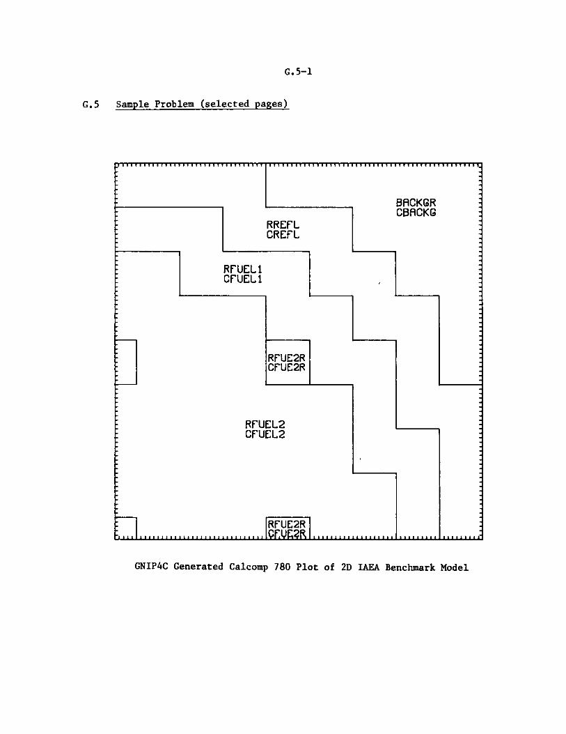
G.5-1
G.5 Sample Problem (selected pages)
BACKGRCBACKG
RREFLCREFL
RFUEL2CFUEL2
RFUE2RCFUE2R
RFUEL2
CFUEL2
RFUE2R
GNIP4C Generated Calcomp 780 Plot of 2D IAEA Benchmark Model

G.5-2
DIF3D 4.0 7/83 **** SAMPLE 5 **** IAEA 2D BENCHMARK - 2. CM MESH
*** DIF3D STORAGE ALLOCATION ***
NUMBER OF WORDS IN DATA STORAGE CONTAINER
MINIMUM NUMBER OF WORDS REQUIRED TO RUN THIS PROBLEM
WITH ALL DATA FOR 1 GROUP IN CORE
WITH SCATTERING BAND OF FLUXES IN CORE "
WITH ALL FILES IN CORE
LOCATION OF SCRATCH FILES DURING STEADY STATE CALCULATION
NO. OF RECORD FILE
FILE CONTENTS RECORDS LENGTH LENGTH
NEW FISSION SOURCE 1 7225 7225
OLD FISSION SRC. I 1 7225 7225
OLD FISSION SRC. 2 1 7225 7225
TOTAL SOURCE 1 7225 7225
COMPOSITION MAP 1 3613 3613
FLUX ITERATE 2 7225 14450
CROSS SECTIONS 2 50 100
FINITEDIFF. COEFS. 2 21675 43350
TOTAL NUMBER OF WORDS USED FOR THIS PROBLEM
/05/84 1616.300 PAGE 14
FCM ECM
200 102000
790
790
790
LOCATION
CORE
CORE
CORE
CORE
CORE
CORE
CORE
CORE
61464
68689
97639
RECORDSIN CORE
2
2
. 790 97639
4.0 7/83 **** SAMPLE 5 **** IAEA 2D BENCHMARK - 2. CM MESH 1/05/84 1616.400 PAGE 2
OUTER ITERATION SUMMIARY REAL SOLUTION K-EFF. PROBLEM
OPTIMIZED INNER ITERATION STRATEGYGROUP OPTIMUM NO. OF GROUP OPTIMUM NO. OF GROUP OPTIMUM NO. OF GROUP OPTIMUM NO. OF
NO. OMEGA INNERS NO. OMEGA INNERS NO. OMEGA INNERS NO. OMEGA INNERS
I 1.56620D+00 14
OUTER REL. POINTIT. NO. ERROR
1 3.686295D-01
2 1.087090D-01
3 5.541415D-02
4 3.550666D-02
5 2.726305D-02
6 2.324552D-02
7 1.954620D-02
8 1.603185D-02
9 1.118446D-02
10 9.360004D-03
11 8.528902D-03
12 6.183622D-03
13 5.174504D-03
14 4.9920180-03
15 3.613034D-03
16 3.187787D-03
17 3.137347D-03
18 2.267487D-03
19 2.010706D-03
20 1.855544D-03
21 1.342631D-03
22 1.279728D-03
23 1.090173D-03
2 1.41751D+00 9
REL. SUM EIGENVALUE PCERROR CHANGE DO
8.812177D-02 1.224134D-02
4.0750310-02 1.235995D-02
2.3805350-02 1.054773D-03
1.769028D-02 6.707207D-04
1.274709D-02 6.574164D-04
9.655415D-03 5.224960D-04
8.190440D-03 3.320014D-04
7.109886D-03 2.622962D-04
5.623376D-03 3.391927D-04
4.863033D-03 2.143255D-04
4.5802300-03 1.056055D-04
3.634297D-03 2.077926D-04
2.9408460-03 1.482553D-04
2.944204D-03 3.461179D-05
2.318619D-03 9.803535D-05
1.740132D-03 7.516984D-05
1.811439D-03 1.2518300-05
1.398910D-03 4.0555900-05
9.980777D-04 3.302212D-05
1.060073D-03 7.416327D-06
8.1239370-04 1.612011D-05
5.6530210-04 1.323734D-05
6.0938800-04 4.7050610-06
OLY. DON. RATIO DON. RATIORIDER USED ESTIMATED K-EFFECTIVE
0 0.0 0.0 1.01224134D+00
0 0.0 4.6958310-01 1.02460129D+00
0 0.0 5.912010D0! 1.02565606D+00
1 5.912010D-01 5.9120100-01 1.02632678D+00
2 5.9120100-01 8.0507480D-01 1.02698420D+00
3 5.9120100-01 8.363244D-01 1.02750669D+00
1 8.3632440-01 8.363244D-01 1.02783870D+00
2 8.3632440-01 9.241546D-01 1.02810099D+00
3 8.363244D-01 9.287023D-01 1.028440180+00
I 9.287023D-01 9.2870230-01 1.02865451D+00
2 9.2870230-01 9.6944330-01 1.02876012D+00
3 9.287023D-01 9.564793D-01 1.02896791D+00
I 9.5647930-01 9.564793D-01 1.02911616D+00
2 9.5647930-01 1.001017D+00 1.02915078D+00
3 9.564793D-01 9.673322D-01 1.02924881D+00
1 9.6733220-01 9.673322D-01 1.02932398D+00
2 9.673322D-01 1.021432D+00 1.02933650D+00
3 9.673322D-01 9.7102630-01 1.02937705D+00
1 9.710263D-01 9.710263D-01 1.02941008D+00
2 9.710263D-01 1.032139D+00 1.029417490+00
3 9.7102630-01 9.729018D-01 1.02943361D+00
1 9.7290180-01 9.729018D-01 1.029446850+00
2 9.729018D-01 1.0401570+00 1.029451560+00
DIF3D 525

G.5-3
DIF3D 4.0 7/83 **** SAMPLE 5 **** IAEA 2D BENCHMARK - 2. CM MESH
OUTER ITERATION SUMMARY REAL SOLUTION
1/05/84 1617.200 PAGE 26
K-EFF. PROBLEM
DOM. RATIOUSED
9.729018D-01
9.740612D-01
9.740612D-01
9.740612D-01
9.740612D-0 1
9.7406120-01
9.740612D-01
9.740612D-01
9.740612D-O1
9.740612D-01
9.740612D-01
9.740612D-01
9.740612D-01
9.740612D-01
DOM. RATIOESTIMATED K-EFFECTIVE
9.740612D-01 1.02945815D+00
9.740612D-01 1.02946344D+00
1.039436D+00 1.02946620D+00
9.740058D-01 1.02946906D+00
9.656760D-01 1.02947123D+00
9.661532D-01 1.02947446D+00
9.647719D-01 1.02947634D+00
9.675397D-01 1.02947782D+00
9.675678D-01 1.02947892D+00
9.696887D-01 1.02947941D+00
9.705203D-01 1.02947967D+00
9.715116D-01 1.02947980D+00
9.724532D-01 1.02947982D+00
9.727809D-01 1.02947979D+00
OUTER ITERATIONS COMPLETED AT ITERATION 37, ITERATIONS HAVE CONVERGED
K-EFFECTIVE - 1.02947978522
GROUP OPTIMUMNO. OMEGA
NO. OMEGA1 1.56620D+00
TO RESTART THIS CALCULATION, INPUT FOLLOWING VALUES
DOMINANCE RATIO (SIGBAR) - 9.727808648906D-O1
OPTIMIZED OVER-RELAXATION FACTORSGROUP OPTIMUM GROUP OPTIMUM GROUP OPTIMUM
NO. OMEGA NO. OMEGA NO. OMEGAGROUP OPTIMUM
2 1.41751D+00
DIF3D 4.0 7/83 **** SAMPLE 5 **** IAEA 2D BENCHMARK - 2. CM MESH 1/05/84 1617.200 PAGE 27
MAXIMUM POWER DENSITY 8.67119D-05 OCCURS AT MESH CELL (I,J,K) - ( 16, 16, 1)
PEAK POWER DENSITY IS CALCULATED BY SAMPLING THE AVERAGE FLUX VALUES ON THE CELL SURFACES AND WITHIN THE CELL.
OUTERIT. NO.
24
25
26
27
28
29
30
31
32
33
34
35
36
37
REL. POINTERROR
7.869962D-04
7.970648D-04
6.211472D-04
4.495778D-04
4.981576D-04
2.378958D-04
1.547608D-04
1.121440D-04
5.678522D-05
3.057508D-05
1.619595D-05
1.375732D-05
1.186071D-05
9.942655D-06
REL. SUMERROR
4.639558D-04
3.202154D-04
3.447927D-04
2.624991D-04
1.793089D-04
1.218137D-04
6.771766D-05
4.944923D-05
2.690326D-05
2.255934D-05
1.594660D-05
1.287818D-05
1.120915D-05
8.340138D-06
EIGENVALUECHANGE
6.597291D-06
5.286035D-06
2.756975D-06
2.867366D-06
2.168207D-06
3.231051D-06
1.876176D-06
1.483748D-06
1.101921D-06
4.901346D-07
2.568945D-07
1.301539D-07
1.520512D-08
-3.135238D-08
POLY.ORDER
3
1
2
3
4
5
6
7
8
9
10
11
12
13
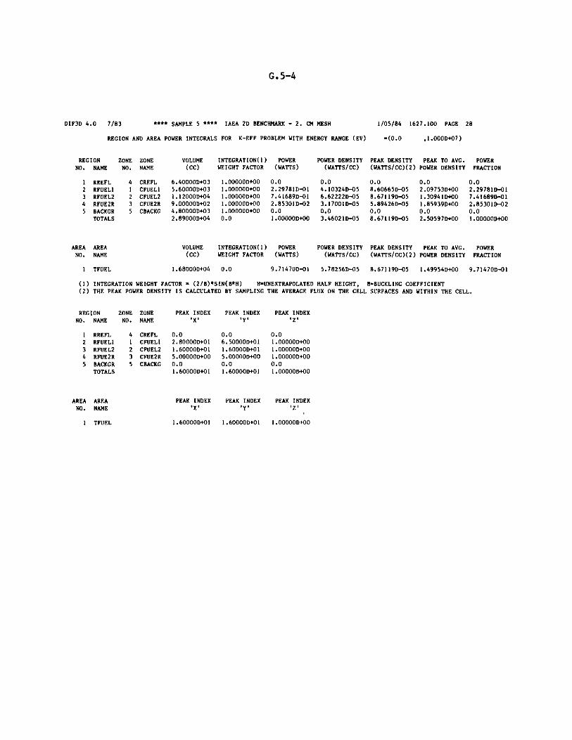
G.5-4
DIF3D 4.0 7/83 **** SAMPLE 5 **** IAEA 2D BENCHMARK - 2. CM MESH
REGION AND AREA POWER INTEGRALS FOR K-EFF PROBLEM WITH ENERGY RANGE (EV)
VOLUME(CC)
6.40000D+035.60000D+031.12000D+049.000OOD+024.80000D+032.89000D+04
INTEGRATION(1) POWERWEIGHT FACTOR (WATTS)
1.00000D+00 0.01.00000D+00 2.29781D-011.00000D+00 7.41689D-O11.00000D+00 2.85301D-021.00000D+00 0.00.0 1.00000D+00
POWER DENSITY(WATTS/CC)
0.04.10324D-056.62222D-053.17001D-05
0.03.46021D-05
1/05/84 1627.100 PAGE 28
-(0.0 ,1.000D+07)
PEAK DENSITY PEAK TO AVG. POWER(WATTS/CC)(2) POWER DENSITY FRACTION
0.0 0.0 0.08.60665D-05 2.09753D+00 2.29781D-018.67119D-05 1.30941D+00 7.41689D-Ol5.89426D-05 1.85939D+00 2.85301D-020.0 0.0 0.08.67119D-05 2.50597D+00 1.00000D+00
AREA AREA VOLUME INTEGRATION(1) POWER POWER DENSITY PEAK DENSITY PEAK TO AVG. POWERNO. NAME (CC) WEIGHT FACTOR (WATTS) (WATTS/CC) (WATTS/CC)(2) POWER DENSITY FRACTION
1 TFUEL 1.68000D+04 0.0 9.71470D-O1 5.78256D-05 8.67119D-05 1.49954D+00 9.71470D-O1
(1) INTEGRATION WEIGHT FACTOR - (2/B)*SIN(B*H) H-UNEXTRAPOLATED HALF HEIGHT, B-BUCKLING COEFFICIENT(2) THE PEAK POWER DENSITY IS CALCULATED BY SAMPLING THE AVERAGE FLUX ON THE CELL SURFACES AND WITHIN THE CELL.
PEAK INDEX PEAK INDEX PEAK INDEX'X' 'Y' 'Z'
0.02.80000D+011.60000D+015.00000D+000.01.60000D+01
0.06.50000D+011.60000D+015.00000D+000.01.60000D+01
0.01.00000D+001.00000D+001.00000D+000.01.00000D+00
PEAK INDEX PEAK INDEX PEAK INDEX'X' 'Y' 'Z'
1.60000D+01 1.60000D+01 1.00000D+00
REGIONNO. NAME
1 RREFL2 RFUELI3 RFUEL24 RFUE2R5 BACKGR
TOTALS
ZONE ZONENO. NAME
4 CREFL1 CFUEL12 CFUEL23 CFUE2R5 CBACKG
ZONE ZONENO. NAME
4 CREFL1 CFUEL12 CFUEL23 CFUE2R5 CBACKG
REGIONNO. NAME
1 RREFL2 RFUEL13 RFUEL24 RFUE2R5 BACKGR
TOTALS
AREA AREANO. NAME
1 TFUEL

G.6-1
G.6 Sample Problem 6 (selected pages)
GNIP4C 11/83 **** BENCHMARK PROBLEM 6 **** IAEA 3D BENCHMARK 10. CM MESH 1/05/84 1628.000 PAGE 44
REACTOR COMPOSITION MAP
Z-DIM MAP FOR PLANES 29 - 36
Y -DIM /X -DIM
1 2 3 4 5 6 7 8 9 10 11 12 13 14 15 16 17***#**#************#***#*******####**********************#****#************##*********
17 * 4 4 4 4 4 4 4* 6 6 6 6 6 6 6 6 6 6* 17* * *
16 * 4 4 4 4 4 4 4* 6 6 6 6 6 6 6 6 6 6* 16*#****# *************** *#**************** *
15 * 1 1 1 1 1* 4 4 4 4 4 4* 6 6 6 6 6 6* 15* * * *
14 * 1 1 1 1 1* 4 4 4 4 4 4* 6 6 6 6 6 6* 14
13 * 2 2 2* 1 1 1 1 1 1* 4 4 4 4* 6 6 6 6* 13* * * * *
12 * 2 2 2* 1 1 1 1 1 1* 4 4 4 4* 6 6 6 6* 12* ********************* ********** *********** *
11 * 2 2 2 2 2 2 2* 1 1 1 1* 4 4 4 4* 6 6* 11* * * * *
10 * 2 2 2 2 2 2 2* 1 1 1 1* 4 4 4 4* 6 6* 10*#**** *********** *****#***** *
9*3* 2 2 2 2 2 2* 3 3* 1 1 1 1* 4 4* 6 6* 9* * * * * * *
8*3* 2 2 2 2 2 2* 3 3* 1 1 1 1* 4 4* 6 6* 8****** ***#**************#** * ***********
7* 2 2 2 2 2 2 2 2 2 2 2* 1 1* 4 4 4 4* 7* * * *
6* 2 2 2 2 2 2 2 2 2 2 2* 1 1* 4 4 4 4* 6* ********** * *********** *
5* 2 2 2* 3 3* 2 2 2 2 2 2* 1 1 1 1* 4 4* 5* * * * * *
4* 2 2 2* 3 3* 2 2 2 2 2 2* 1 1 1 1* 4 4* 4* *********** *********** * *
3* 2 2 2 2 2 2 2 2 2 2 2 2 2* 1 1* 4 4* 3* * * *
2* 2 2 2 2 2 2 2 2 2 2 2 2 2* 1 1* 4 4* 2**** ******* * *
1*3* 2 2 2 2 2 2* 3 3* 2 2 2 2* 1 1* 4 4* 1
1 2 3 4 5 6 7 8 9 10 11 12 13 14 15 16 17
DIF3D 4.0 7/83 **** BENCHMARK PROBLEM 6 **** IAEA 3D BENCHMARK 10. CM MESH 1/17/84 1044.700 PAGE 51
*** DIF3D STORAGE ALLOCATION ***FCM ECM
NUMBER OF WORDS IN DATA STORAGE CONTAINER - 8000 166000
MINIMUM NUMBER OF WORDS REQUIRED TO RUN THIS PROBLEM
WITH 3 PLANES FOR 1 GROUP IN CORE - 390 7142
WITH ALL DATA FOR 1 GROUP IN CORE - 390 93697
WITH SCATTERING BAND OF FLUXES IN CORE - 390 104679
WITH ALL FILES IN CORE - 390 159649
LOCATION OF SCRATCH FILES DURING STEADY STATE CALCULATION
NO. OF RECORD FILEFILE CONTENTS RECORDS LENGTH LENGTH
NEW FISSION SOURCE 1 10982 10982
OLD FISSION SRC. 1 1 10982 10982
OLD FISSION SRC. 2 1 10982 10982
TOTAL SOURCE 1 10982 10982
COMPOSITION MAP 1 5491 5491
FLUX ITERATE 2 10982 21964
CROSS SECTIONS 2 60 120
FINITEDIFF. COEFS. 2 43928 87856
LOCATION
CORE
CORE
CORE
CORE
CORE
CORE
CORE
CORE
RECORDSIN CORE
TOTAL NUMBER OF WORDS USED FOR THIS PROBLEM - 390 159649

G.6-2
DIF3D 4.0 7/83 "*** BENCHMARK PROBLEM 6 **** IAEA 3D BENCHMARK 10. CM MESH
OUTER ITERATION SUMMARY REAL SOLUTION K-EFF. PROBLEM
1/17/84 1044.800 PAGE 63
OPTIMIZED INNER ITERATION STRATEGYGROUP OPTIMUM NO. OF GROUP OPTIMUM NO. OF GROUP OPTIMUM NO. OF GROUP OPTIMUMNO. OMEGA INNERS NO. OMEGA INNERS NO. OMEGA INNERS NO. OMEGA
I 1.16565D+00 5
OUTER REL. POINTIT. NO. ERROR
I 2.771832D-01
2 1.760958D-01
3 1.1987570-01
4 9.499101D-02
5 6.828438D-02
6 4.924479D-02
7 4.094458D-02
8 3.579333D-02
9 2.692639D-02
10 2.109728D-02
11 2.019927D-02
12 1.739404D-02
13 1.417054D-02
14 1.337218D-02
IS 1.095615D-02
16 8.621393D-03
17 8.442859D-03
18 7.234700D-03
19 5.804683D-03
20 5.543135D-03
21 4.485072D-03
22 3.474716D-03
23 2.604693D-03
2 1.08039D+00 4
REL. SUM EIGENVALUE PCEkROR CHANCE OF
I.0244385-01 3.830969D-03
5.806885D-02 1.040214D-02
3.941884D-02 3.010733D-03
3.088157D-02 1.9575330-03
2.3282660-02 2.019555D-03
1.7843129-02 1.7446259-03
1.5256530-02 1.071401D-03
1.3575149-02 7.4864340-04
1.098765D-02 1.034374D-03
9.372968D-03 7.2419879-04
8.7897259-03 3.3786080-04
7.2450020-03 5.705062D-04
5.8614429-03 4.9263380-04
5.642111D-03 1.6751439-04
4.6581830-03 2.4413380-04
3.5968020-03 2.380209D-04
3.5066220-03 8.598459D-05
2.8767180-03 8.8206950-05
2.1702800-03 9.3395720-05
2.1242189-03 4.543612-05
1.7374120-03 2.830801-05
1.3056279-03 3.3804359-05
9.4247050-04 2.8115089-05
OLY. DOM. RATIO DOM. RATIORIDER USED ESTIMATED K-EFFECTIVE
0 0.0 0.0 1.00383097D+00
0 0.0 5.729916D-01 1.01423311D+00
0 0.0 6.8921150-01 1.01724384D+00
I 6.892115D-01 6.8921151-01 1.01920138D+00
2 6.892115D-0I 8.4431290-01 1.02122093D000
3 6.892115D-01 8.7209900-01 1.022965760+00
1 8.720990D-01 8.7209900-01 1.024037160+00
8.720990D-01
8.720990D-01
9.4459830-01
9.445983D-01
9.445983D-01
9.6490090-01
9.649009D-0 I
9.649009D-01
9.705796D-01
9.705796D-01
9.7057960-01
9.7159930-01
9.715993D-01
9.715993D-01
9.7159930-01
9.715993D-01
9.410N500-01 1.02478580D+00
9.445983D-01 1.02'82017D+00
9.445983D-01 1.02654437D+00
9.695127D-01 1.02688223D+00
9.649009D-01 1.027452741+00
9.649009D-01 1.02794537D+00
9.823799D-01 1.028112890+00
9.705796D-01 1.02835702D+00
9.705796D-01 1.028595040+009.8831360-01 1.02868103D+00
9.7159930-01 1.02876923D+00
9.715993D-01 1.02886263+00O
9.8989491-01 1.02890807D+00
9.714718D-01 1.028936370+00
9.690728D-01 .028970180+00
9.6903680-01 I.028998290+00
D1F3D 4.0 7/83 **** BENCHMARK PROBLEM 6"**** IAEA 3D BENCHMARK 10. CM MESH 1/17/84 1044.900 PACE 64
OUTER ITERATION SUMMARY REAL SOLUTION K-EFF. PROBLEM
OUTER REL. POINT REL. SUM EIGENVALUE POLY. DOM. RATIO DOM. RATIOIT. NO. ERROR ERROR CHANGE ORDER USED ESTIMATED K-EFFECTIVE
1.937053D-03 6.6071910-04 1.9917670-05 6
1.411882D-03 4.769696-04 1.3100000-05 7
9.602456D-04 3.509338D-04 8.5625950-06 8
6.6078080-04 2.807478D-04 5.6000650-06 9
5.090272D-04 2.3400010-04 3.6400090-06 I
5.108685D-04 2.410647D-04 2.8553070-06 2
4.819845D-04 2.155923D-04 8.128949D-07 3
4.476779D-04 1.898788D-04 7.8233960-07 I
4.4729550-04 1.905386D-04 -1.4694850-07 2
3.860226D-04 1.707806D-04 7.5107600-07 3
3.3656500-04 1.444165D-04 8.1735460-07 4
2.9052890-04 1.190343D-04 7.129103D-07 5
2.3333740-04 9.5058.54D-05 5.2500850-07 6
1.8653280-04 7.591994.-05 3.521412D-07 7
1.402165D-04 6.0360840-05 2.1590310-07 8
1.010335D-04 4.793465D-05 1.020897D-07 9
8.130474D-0S 3.8393840-05 2.1323650-08 10
6.4328670-05 2.9768320-05 -3.466991D-08 11
4.7545410-05 2.3413300-05 -7.725147D-08 12
3.5532140-05 1.726704D-05 -1.005624D-07 13
2.6551729-0S 1.3003799-05 -1.092027D-07 14
1.8360769-05 9.043078D-06 -1.104239D-07 IS
1.3485970-05 6.4352470-06 -1.0328080-07 16
1.0286560-05 4.4363570-06 -9.0637900-08 17
8.778839D-06 3.0196380-06 -7.6535970-08 18
9.7159930-01 9.692004D-01 1.02901821D+00
9.715993D-01 9.699473D-01 1.029031311+00
9.715993D-01 9.706347D-01 1.02903987D+00
9.7159939-01 9.717033D-01 1.02904547D+00
9.717033D-01 9.717033D-01 l.02904911D+00
9.717033D-01 1.015566D+00 1.0290597D+00
9.717033D-01 9.8872330-01 1.029052780+00
9.887233D-01 9.887233D-01 1.02905356D00
9.887233D-01 1.001790D+00 1.02905342D+00
9.887233D-01 9.865745D-01 1.02905417D+00
9.887233D-01 9.843849D-01 1.02905499D+00
9.8872330-01 9.846099D-01 1.02905570D+00
9.887233D-01 9.849260D-01 1.02905622D+009.887233D-01 9.855128D-01 1.02905658D+00
9.887233D-01 9.860203D-01 1.02905679D+00
9.887233D-01 9.8644200-01 1.02905689D+009.887233D-01 9.868250D-01 1.02905692D+00
9.887233D-01 9.870009D-01 1.02905688D+00
9.887233D-01 9.872028D-01 1.02905680D+00
9.887233D-01 9.872144D-01 1.029056701+00
9.887233D-01 9.872958D-01 1.02905659D+00
9.887233D-01 9.872579D-01 1.02905648D+00
9.887233D-01 9.872922D-01 1.02905638D+00
9.887233D-01 9.873148D-01 1.02905629D+00
9.887233D-0l 9.873501D-Ol 1.02905621D+00
NO. OFINNERS
24
25
26
27
28
29
30
31
32
33
34
35
36
37
38
39
40
41
42
43
44
45
46
47
48

G.6-3
DIF3D 4.0 7/83 **** BENCHMARK PROBLEM 6 **** IAEA 3D BENCHMARK 10. CM MESH
OUTER ITERATIONS COMPLETED AT ITERATION 48, ITERATIONS HAVE CONVERGED
K-EFFECTIVE - 1.02905621257
1/17/84 1044.900 PAGE 65
TO RESTART THIS CALCULATION, INPUT FOLLOWING VALUES
DOMINANCE RATIO (SIGBAR) - 9.873501094068D-01
OPTIMIZED OVER-RELAXATION FACTORSGROUP OPTIMUM GROUP OPTIMUM GROUP OPTIMUM GROUP OPTIMUM GROUP OPTIMUM
NO. OMEGA NO. OMEGA NO. OMEGA NO. OMEGA NO. OMEGA1 1.16565D+00 2 1.08039D+00
MAXIMUM POWER DENSITY 4.29119D-07 OCCURS AT MESH CELL (I,J,K) - ( 4, 3, 18)
PEAK POWER DENSITY IS CALCULATED BY SAMPLING THE AVERAGE FLU! VALUES ON THE CELL SURFACES AND WITHIN THE CELL.
DIF3D 4.0 7/83 **** ENCHMARK PROBLEM 6 **** IAEA 3D BENCHMARK 10. CM MESH
REGION AND AREA POWER fl EGRALS FOR K-EFF PROBLEM WITH ENERGY RANGE (EV) -(0.0
REGIONNO. NAME
I RREFL2 RFUELI3 RFUEL24 RFUE2R5 RREFLR6 BACKCR
TOTALS
ZONE ZONENO. NAME
4 CREFL.I CFUEL12 CFUEL23 CFUE2R5 CREFLR6 CBACKG
VOLUME(CC)
3.11400D+061.90400D+063.77600D+063.38000D+052.60000D+041.82400D+061.09820D+07
INTEGRATION( 1)WEIGHT FACTOR
1.00000D+001.00000D+001.00000D+001.0000D+00I.00000D+O01.000U'OD+00U.
0
POWER(WATTS)
0.02.06648D-017.64862D-012.84906D-020.00.01.00000D+00
POWER DENSITY(WAT'S/CC)
0.01.08534D-072.02559D-078.42918D-080.00.09.10581D-08
PEAK DENSITY(WATTS/CC)(2)
0.03.452211-0/4.29119D-072.77697D-070.00.04.29119D-07
1/17/84 1046.300 PAGE 66
,1.000D+07)
PEAK TO AVG. POWERPOWER DENSITY FRACTION
0.0 0.03.18078D+00 2.066481D-012.11849D+00 7.64862D-013.29447D+00 2.84906D-020.0 0.00.0 0.04.71258D++0 1.00000D+4J
AREA AREA VOLUME INTEGRATION(1) POWER POWER DENSITY PEAK DENSITY PEAK TO AVG. POWERNO. NAME (CC) WEIGHT FACTOR (WATTS) (WATTS/CC) (WATTS/CC)(2) POWER DENSITY FRACTION
1 TFUEL 5.68000D+06 0.0 9.71509D-01 1.71040D-07 4.29119D-07 2.50887D+00 9.71509D-01
(1) INTEGRATION WEIGHT FACTOR " (2/B)*SIN(B*H) H"UNEYTRAPOLATED HALF HEIGHT, B-BUCKLING COEFFICIENT(2) THE PEAK POWER DENSITY IS CALCULATED BY SAMPLING THE AVERAGE FLUX ON PHE CELL SURFACES AND WITHIN THE CELL.
ZONE ZONENO. NAME
4 CREFL1 CFUEL12 CFUEL23 CFUE2R5 CREFLR6 CBACKG
PEAK INDEX PEAK INDEX PEAK INDEX'X' 'Y'''
0.01.30000D+014.00000D+001.00000D+000.00.04.00000D+00
0.0 0.06.00000D+00 1.80000D+013.00000D+00 1.80000D+011.00000D+00 1.80000D+010.0 0.00.0 0.03.00000D+00 1.8000D+01
AREA AREA PEAK INDEX PEAK INDEX PEAK INDEX POWER DENSITY PEAK TO AVG.NO. NAME 'X' 'Y' 'Z' AXIAL (3) P.D. AXIAL (3)
1 TFUEL 4.00000D+00 3.00000D+00 1.80000D+01 2.64605D-07 1.62174D+00
(3) DERIVED FROM DATA IN THE AXIAL COLUMN OF MESH CILLS THAT INTERSECTS THE REACTOR PEAK POWER DENSITY LOCAtION
REGIONNO. NAME
2 RREFL2 RFUELI3 RFUEL24 RFUE2R5 RREFLR6 BACKGR
TOTALS

Distribution for ANL-82-64
Internal:
C.C.E.J.S.H.R.M.S.J.S.B.Y.P.R.D.T.J.K.D.K.E.P.J.E.C.C.H.R.
H. AdamsL. BeckS. BeckjordC. BeitelK. BhattacharyyaBigelowN. BlomquistM. BretscherB. BrumbachE. Cahalan
G. CarpenterR. ChandlerI. Chang1. CollinsJ. CornellaC. CutforthA. DalyR. DeenL. Derstine (10)R. FergusonE. FreeseK. FujitaJ. GarnerM. GasidloM. GelbardL. GrasseschiM. GreenmanHenrysonHosteny
H.R.R.H.T.R.W.R.L.J.M.D.J.H.R.D.L.F.A.Y.E.P.P.R.J.R.G.R.J.
H. HummelN. HwangE. KaiserKhalilKraftD. LawrenceK. LehtoM. LellG. LeSageR. LiawJ. LineberryJ. MalloyE. MatesF. McFarlaneD. McKnightMeneghettiE. MeyerMoszurOlsonOrechwaM. PenningtonJ. PersianiA. PizzicaB. PondR. RossR. RudolphK. RuschW. SchaeferE. Schofield
External:
DOE-TIC, for distribution per UC-79d (117)Manager, Chicago Operations Office, DOEDirector, Technology Management, DOE-CHDirector, DOE-BRP (2)Applied Physics Division Review Committee:
P. W. Dickson, Jr., Clinch River Breeder Reactor Project, Oak RidgeW. E. Kastenberg, University of CaliforniaK. D. Lathrop, Los Alamos National LaboratoryN. J. McCormick, University of WashingtonD. A. Meneley, Ontario HydroJ. E. Meyer, Massachusetts Inst. TechnologyA. E. Wilson, Idaho State University
H. Alter, Office of Breeder Technology, DOEAdvanced Reactor Library, Westinghouse Electric Co., Madison, PaM. Becker, Rensselaer Polytechnic Inst.R. A. Bernnett, Westinghouse Hanford Co.F. W. Brinkley, Los Alamos National LaboratoryS. P. Congdon, General Electric Co.
a
D. ShaftmanD. M. SmithK. S. SmithJ. L. SnelgroveC. G. StenbergW. J. SturmS. F. SuB. J. ToppelA. TravelliR. B. TurskiA. J. UlrichR. VilimD. C. WadeD. P. WeberW. L. WoodruffS. T. YangB. S. YarlagaddaANL Patent Dept.ANL Contract FileANL Libraries (2)TIS Files (6)AP Division File (10)

C. Cowan, General Electric Co.
H. L. Dodds, Technology for Energy Corp.R. Doncals, Westinghouse Electric Corp.J. J. Dorning, University of IllinoisM. J. Driscoll, MITC. Durston, Combustion EngineeringR. Ehrlich, General Electric Co.H. Farrar IV, Atomics InternationalFast Breeder Dept. Library, General Electric Co.Y. C. Feng, General Electric Co., San JuseG. F. Flanagan, Oak Ridge National LaboratoryN. M. Greene, Oak Ridge National LaboratoryD. R. Harris, Rensselaer Polytechnic Inst.A. Hartman, General Electric Co., SunnyvaleP. B. Hemmig, Reactor Development and Demonstration, DOEA. F. Henry, MITJ. Kallfelz, Georgia Institute of TechnologyR. Karam, Georgia Institute of TechnologyW. Y. Kato, Brookhaven National LaboratoryR. J. LaBauve, Los Alamos National LaboratoryJ. Lewellen, Reactor Development and Demonstration, DOEE. E. Lewis, Northwestern UniversityM. D. Libby, NUSCOR. MacFarlane, Los Alamos National LaboratoryF. C. Maienschein, Oak Ridge National LaboratoryD. R. Marr, Los Alamos National LaboratoryD. R. Mathews, GA TechnologiesD. R. McCoy, Los Alamos National Laboratory (3)H. A. Morowitz, Tarzana, CAD. Moses, Oak Ridge National LaboratoryJ. Naser, Electric Power Research Inst.National Energy Software Center, ANL (10)R. J. Neuhold, Reactor Development and Demonstration, DOER. D. O'Dell, Los Alamos National LaboratoryD. Okrent, University of CaliforniaK. Ott, Purdue University0. Ozer, Electric Power Research Inst.A. M. Perry, Oak Ridge National LaboratoryC. Porter, Westinghouse Electric Corp.J. Prabulos, Combustion EngineeringR. Protsik, General Electric Co.A. B. Reynolds, University of VirginiaW. A. Rhoades, Oak Ridge National LaboratoryP. Rose, Brookhaven National LaboratoryD. H. Roy, Babcock and Wilcox Co.R. Schenter, Westinghouse Hanford Co.P. Soran, Los Alamos National LaboratoryE. R. Specht, Atomics InternationalS. Stewart, General Electric, Co.L. E. Strawbridge, Westinghouse Electric Corp.R. J. Tuttle, Atomics InternationalD. R. Vondy, Oak Ridge National LaboratoryJ. E. Vossahlik, GRP Consulting, Inc.C. Weisbin, Oak Ridge National LaboratoryJ. White, University of Lowell
b