itb 1 - efs · the itb injection system test bench has been developed for research &...
TRANSCRIPT

1
Injection Test Bench for the complete system
ITB ITB
The ITB injection system test bench has been developed for Research & Development applications. The same bench enables automatic testing of individual elements or of the complete injection system and can adapt to unit pumps, injection pumps or common rail systems.

2
Overview
Complete injection systems
Common rail systems•Unit pumps•Inline pumps•Distribution pumps•Injectors•Injector-pumps•
ITV
Overview

Advantages
3
Overview
As well as being made-to-measure to your specifications, this test bench will give you •
the maximum in flexibility for your Research and Development application - with an EFS
bench, whatever you want to test, you can.
The research test bench allows you to choose between a manual driving mode, giving you •
instantaneous results when you change a parameter or an automatic mode, where fully
programmable cycles will give you in-depth information on numerous parameters.
You choose what you want to test and how: • set-ups can be changed easily, equipment can
be adapted or added;
a single test bench will allow a huge range of different tests, providing you with a high
degree of flexibility.
Choose between a fully-loaded version that is • ready-to-use or a more basic version that
is adaptable to meet your specific needs.
If you have already invested in measurement devices, • an EFS test bench can be adapted
to your existing measurement systems.
Whatever you choose to do with your test bench, the task will be made easy by a simple •
intuitive software interface, enabling you to switch between modes, modify set-ups,
focus on particular parameters or process test results ●
... with an EFS bench, whatever you want to test, you can

4 Final test of a complete system
test one element or several at a time
Overview

5
Testing element by element
test one element or several at a time
Overview

6
Overview
Precise, reliable multi-channel measurement
The motorization adapted to your needs: (cars or light trucks, heavy-duties, off-road)
Safe, reliable coupling
The ITB 640r bench

7
Overview
Extractible drawer: an easy-access «oil station»
High-performance supervision software
A large, adaptable work zone

Description
8
Key features
Operations cabin:
• Working surface: 1.4 m2 (D: 1090 x W: 1180)• Working volume: 1.2 m3 (H: 900)
Tubular steel structure fitted with •removable closing panelsThermoset epoxy coating•Standard color = RAL 7035 •Other RAL values awailable on request
Fully adaptable workspace to meet your specifications.
Doors are treated for acoustic noise reduction and for safety.
User area

9
TECHNICAL FEATURES
Lighting provided by a safety fluorescent tube •Locking and opening protection by safety contactors•Primary oil tank and circuitry made of stainless steel•Distribution of fluids through 10 openings (BSP¾’’)•Cable-pass trap doors and ducts for the necessary cables•
Access via two glassed-in, removable doors

10
The bench can be adapted to any type of pump or system
The pump support is designed for installing:
in-line pumps for mechanical injection systems •high pressure pumps for "common rail" systems •unit injection pumps systems •
Wide support with 3 "T" fixation grooves, length = 1400mm, width = 300mm.
Pump support and motor are fitted on a specially designed beam, mounted on vibration dampers.
If there is not adaptors for your pump, EFS will realised it.
Pump support

11
The coupling equipment is inserted between the inertial flywheel and the injection pump to transmit drive motor torque to the pump. It is made up of:
Torque limiter•Coupling•Cone shaped pump adaptor•
Provides torque transfer and the easy coupling /uncoupling of the pump.
CouplingRoba - DS Size 100 Size 160
Coupling nominal torque 1000 Nm 1600 Nm
Maximum speed 7300 rpm 6200 rpm
Axial displacement (DKa) ±2.1 mm ±2.1 mm
Radial misalignment on flange (DKr) 0.45 mm 0.55 mm
Radial misalignment on sleeve (DKr) 2.1 mm 2.2 mm
Angular misalignment (DKw) 1° 1°
Tightening torque 35 Nm 69 Nm
Minimizes the consequences in the event of a pump blockage
Torque limiter
Coupling
Coupling equipement

12
Standard motor· 34 KW asynchronous motor with inertial flywheel· Maximum speed: up to 4000 rpm· Engine torque: 328Nm @ 1000 rpm.· Speed variator: 37KW
Standard motor: 160L
Cone-shaped pump adaptor
4 adaptor diameters available : 20, 25, 30 and 35mm
Adapts to any type of pump
Pump driving equipement

13
Asynchronous motortype BQCP P at1000rev/min (kW) Torque (Nm)160S 25.2 241
160L 34.3 328
P at 1500rev/min (kW) Torque (Nm)160S 36 229
160L 49 312
Other motorizations available on the standard beam

14
Fluid conditioning unit
Extractible drawer
PRIMARY TANK FOR TEST FLUID
Volume: 90 l•Type of fluid: Shell ISO 4113 Normafluid BR, •Exxsol D80, VISCOR 1487Fluid filtration at the output of the tank: 90 µm•
The hydraulic area will meet your requirements in terms of flow provided and temperature regulation
HIGH PRESSURE PUMP GATHERING
Flow: 30 l/min•Regulated pressure driven by PC: 0.6 to 6 bars •Primary filtration: 10 µm•
TEST FLUID REGULATION CIRCUIT
Flow: 27 l/min•Heating resistor power: 3 kW•Cooling exchanger water/fluid power: 8 kW•Time to heat the fluid from 20 to 40°C: 30 minutes•Temperature regulation range: 20 µ (*) to 70°C•Temperature regulation precision: ±1° C•(*) : depending on cooling water temperature (minimum •bench temperature is 5°C above water temperature)
OPTIONS
additionnal automotive filter installed near the high •pressure pump: 3 µm (ITB640R - 24)optional regulation from 0.1 to 2 bars • (ITB640R - 23)

15
Pump lubrication
LUBRICATION OIL CIRCUIT
Flow: 4 l/min•Pressure regulation (manually controlled): 0.5 to 6 bars•Filtration: 25 µm (at the tank return)•Tank capacity: 20 l•Tank temperature measurement•
COOLING CIRCUIT FOR MEASUREMENT DEVICE
Flow: 12 l/min•Regulated pressure (manually controlled): 0.6 to 6 bars •Filtration: 10 µm•
OPTION
tank temperature regulation (cold only) • (ITB640R - 25)

16
AIR CIRCUIT
Flow: 1m3 per hour•Quality: dry air without oil•Maximum input pressure: 10 bars•Minimum input pressure: 6 bars•Input filter inside the bench: •5 µm wih fluid separator
WATER COOLING CIRCUIT
Flow: 25 l/min•Maximum input pressure: 3 bars•Minimum input pressure: 2 bars•Maximum output pressure: 1 bar•Acceptable temperature range: 10 to 15 °C •(temperatures above 15°will have an impact on the minimum test fluid temperature)
Heaters and water cooling exhangers
OPTION
regulated output for pneumatic pump •0 - 2 bars (ITB640R - 21)

17
The bench electrical cabinet incorporates all the electrical power cabling and all the safety elements. Naturally, it includes an inverter which is adapted to the motor and also to the site conditions (maximal temperature in the bench area, altitude above sea level).
It also features several electric filters for full compliance with EMC standards.
A circuit breaker is installed at the mains power input. It requires a 3-phase 400 V AC mains supply, 50 or 60 Hz with maximum 60 kVA.
It also contains all of the electrical components for motor driving and temperature regulation.
Additional features include :
- a 230 V AC converter for internal electronics
- a safety PLC which also integrates DC measurement
- a DC supply for conditioning devices (eg. temperature and pressure)
- an electrical interface between the user area and the electrical cabinet
Bench electrical area

A password is requested, in order to prevent unauthorized users from entering this mode.
18
The doors are locked during the tests to protect the user from rotating parts and pressurized elements.
The doors are unlocked only when the electrical motor is stopped and when the pressure has fallen to the low limit defined via the supervision software.
DOORS LOCKING
In order to allow maintenance and settings while the bench is running, it can be set to «Door open» mode.
«DOOR OPEN» MODE
Safety locking devices ensure that both doors are locked while the bench is running. The user is informed of the locking status.
Key features
Safety

19
SIGNAL LIGHT TOWER
EMERGENCY STOP
SIGNAL LIGHTS
The bench is equipped with two emergency buttons.
Should an emergency stop occur, the motor is quickly slowed, all functions are disabled and the bench is set to GENERAL STOP mode.
An error message is sent to the supervisor to inform the user of the cause.
A GREEN light indicates that the bench is working correctly and no malfunction is indicated.
An ORANGE light indicates an alarm, but the test bench can continue to operate.
A RED light indicates a major malfunction and the test bench is stopped.
The operating state of the test bench is indicated by the column "GREEN /ORANGE/RED" situated ABOVE THE ELECTRICAL CABINET:
Control lights are installed on each side of the bench. They inform the user of the operational status of the bench.

IFR
MIQ
20
Quantity injected : •précision 0.6mg/shot Shot to shot measurement•Opening and closing time•5 injections per revolution•
The MIQ (Mono Injector Qualifier) is de-signed to drive an electronic injector in order to measure “stroke-by-stroke” injection volumes.
The IFR (injection Flow and Rate) is an instantaneous mass flowmeter enabling you to measure up to 10 injections per revolution.
MEASURES SHOT TO SHOT FLOW ...
... AND/OR INJECTION RATE
Quantity injected : •accuracy: 0.1mg/shot Injection rate•Opening and closing time•10 injections per revolution•
Key features

21
DRIVING WITHOUT ECU
DRIVING WITH YOUR OWN ECU
An IPoD power dri-vers for coil and piezo injector driving.
An APC for programming signals coming from an angular encoder to synchronize ECU with the bench and the measuring devices.
An HPC for high-pressure regulation.

22
Easy to use ...
The electrical connections are made with cables specifically adapted for your application using industrial connectors and long term reliable oil -proof cables.
The supervision screen and keyboard are installed inside the cabinet
Quick connectors for hydraulic connections mean that the pump can be installed in minutes
Key features
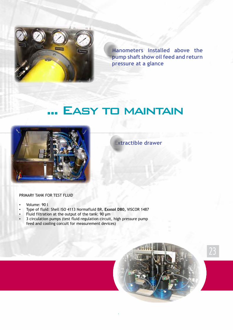
23
Extractible drawer
PRIMARY TANK FOR TEST FLUID
Volume: 90 l•Type of fluid: Shell ISO 4113 Normafluid BR, • Exxsol D80, VISCOR 1487 Fluid filtration at the output of the tank: 90 µm•3 circulation pumps (test fluid regulation circuit, high pressure pump •feed and cooling corcuit for measurement devices)
Manometers installed above the pump shaft show oil feed and return pressure at a glance
... Easy to maintain

Software
24
oil temperature regulation at the •input or output of the high pumpcabin door• opening controllubrication pump• controlfeed pump• controlelectric motor• controlpower supply • providing the battery voltage controlrail pressure• control
Alarm and error displays
Control every element of the bench
You can control every element of the test bench: start and stop every device (F1)
Supervision software

25
the heart of the system
F2: for instantaneous measurement display
F3: for average measurement display
F4: for detailed visualization of each channel
F5: for MIQ display and settings
F6: for applying injector cycles
F7: for injector comparison

26
Supervision software
Visualize comparative graphs, averages and digital injected values from injectors 1 to 6 (F7)
- Maximum values- Minimum values- Instantaneous values- Average values- Standard deviations
Monitor the instantaneous measurement of the six injections (F2)
- Maximum values- Minimum values- Instantaneous values- Average values- Standard deviations
Supervision software

27
Display a complete set of data for a single injector(F4)
Drive and read data from the ECU, even during measurement cycles using the ECU control PC

28
Set up signals provided by the angular pulse converter (APC):
- Driving motor signals- N/rev signals- Cam signals- Crank signals
Crank signal
Cam signal
Supervision software
1/rev
crank TTL
crank analog
1/rev
cam TTL
cam analog
Choose the cam/pump ratio you require

29
At the end of the acquisition period, the supervision software will store all the results in the .
Create and run measurement cycles for the injectors (F6) - easy cycle pattern creation- wide range of driving parameters - all cycle values and measurement results accessible as cycle output

This database is linked with our “Chart display” graphical software which will display all the results in the same graphic.
Injection rate at different pulse lengths and
at different pressures
Quantity versus pulse length at different pressures
Pump torque and speed at different
pressures
30
Electrics
graphic results
Compare all the signals on the same scale in a single graphic

31
Electronics cabinet
The electrical cabinet includes:
A • supervision PC. An embedded PC adapted for harsh conditions, running under Windows XP. It provides Ethernet and serial links for connecting to ECU and/or IFR, MCF, IMCF.
The • DC power supply programmable from 0 to 40 V DC for external components such as the ECU.
The • APC connected to the 2x3600 pulses/revolution and 1/revolution encoder fixed to the motor. It provides all the necessary synchronization signals for the IFR, MCF and ECU.
These three elements are provided as standard with the bench
All of these following devices are optional and can be purchased with the bench or later on
This measuring cabinet is linked by a long cable to the bench. It is wired for up to 6 measuring devices such as the IFR or MIQ as well as the HPR (high pressure rail regulator) and the piezo or coil IPoDs.
In order to best meet your needs, EFS offers numerous different configurations. Some examples...
Electrics

Specifications
32
ELECTRICAL POWER SUPPLY REQUIREMENTS BENCH Type Three-phase (3 Ph + ground) Voltage 400 V ±10% Frequency 50 Hz / 60 Hz Maximum current (power) 160S - 1000: 84.5 A (58.5 kVA)
160S - 1500: 92.2 A (62.7 kVA)160L - 1000: 92.2 A (62.7 kVA)
160L - 1500: 120 A (81.6 kVA) ELECTRICAL CABINET Type Single-phase (P + N + G) Voltage 230 V ±10% Frequency 50 Hz / 60 Hz Maximum current 40 A Power 9.2 kVA
BENCH REQUIREMENTS Test fluid Type: ISO 4113 Normafluid BR, 90 liters Lubrication fluid Type: Prestigrade diesel oil SAE15/40, 20 liters Pneumatic needs Input pressure: 6 bars Flow: 10l/min Air filtration level: 30µm Ventilation Air Vent Æ on the bench: 120 mm Required ventilation: 120m3/h
Technical specifications

33
Technical specifications
FLUID CONDITIONINGEXTRACTIBLE DRAWER
PRIMARY TANK FOR TEST FLUIDTank capacity 90lType of fluid Shell ISO4113 - Normafluid BR (V-oil 1404),
Exxsol D80, VISCOR 1487, others available on request
Fluid filtration at the output of the tank 90 µmTEST FLUID REGULATION CIRCUIT Flow 27l/minHeating resistor power 3kWCooling exchanger water/fluid power 8kWTime to heat the fluid from 20 to 40°C 30 minutesTemperature regulation range 20 to 70 °CTemperature regulation precision ±1°CHIGH PRESSURE FEED PUMPFlow 30l/minRegulated pressure (driven by PC as an option) 0.6 to 6 barsPrimary filtration 10 µmAdditionnal automotive filter (option) 3 µmCOOLING CIRCUIT FOR MEASUREMENT DEVICEFlow 12l/minRegulated pressure (manually controlled) 0.6 to 6 bars
PUMP LUBRICATION SYSTEMFlow 4l/minPressure regulation (manually controlled) 0.5 to 6 barsFiltration 30µmTank capacity 20l
HEATERS AND WATER COOLING EXCHANGERSWATER COOLING CIRCUITFlow 25l/minMinimum/Maximum input pressure 2 / 3 barsMaximum output pressure 1 barAcceptable temperature range 10 to 15° CAIR COOLING CIRCUITFlowMaximum/minimum pressure 10 / 6 barsInput filter inside the bench 5 µm with fluid separatorQuality

34
Technical specifications
height : 2.5 m
LAYOUT

References
35
ITB

36
Broc
hure
Ban
c ET
UD
E
V3.0
21
-01-
2014
SITE ADDRESSParc d’activité du Baconnet192 Allée des Chênes69700 MONTAGNYFRANCE
SUBSIDIARY IN CHINA providing technical support - installation, training, maintenance and calibration
TELEPHONE & E-MAIL Tel.: +33 (0)4 72 49 27 72Fax: +33 (0)4 72 49 27 77e-mail: [email protected]: www.injection.efs.fr