item 400 piling - dotr -...
TRANSCRIPT

81
ITEM 400 – PILING
400.1 Description
400.1.1 Scope
This Item shall consist of piling, furnished, driven or placed, cut and spliced in accordance with this Specification and in reasonably close conformity with the Plans.
The Contractor shall furnish the piles in accordance with an itemized list, which will be provided by the Engineer, showing the number and lengths of all piles. When cast-in-place concrete piles are specified on the Plans, the Engineer will not furnish the Contractor an itemized list showing the number and length of piles. When test piles and load tests are required in conformance with Sub-section 400.1.2 and 400.1.3, respectively, the data obtained from driving test piles and making test loads will be used in conjunction with other available sub-soil information to determine the number and lengths of piles to be furnished. The Engineer will not prepare the itemized list of piles for any portion of the foundation area until all specified loading tests in the Contract representative of the portion have been completed.
In determining lengths of piles for ordering and to be included for payment, the lengths given in the order list will be based on the lengths which are assumed to remain in the completed structure. The Contractor, shall, without added compensation, increase the lengths to provide for the fresh heading and for such additional length as maybe necessary to suit the Contractor’s method of operation.
400.1.2 Test Piles
For his own information, the Contractor may drive at the location of the regular piles indicated on the Plans such test piles as he may consider necessary in addition to the test piles specified in the Contract and shall be considered as regular piles. When called for in the Bill of Quantities, a pile if required to be subjected to load test shall conform to the provision as provided in Subsection 400.1.3, Load Tests. The Contractor shall furnish and drive test piles of the dimensions and at the locations designated by the Engineer. They shall be of the material shown in the Bill of Quantities and shall be driven to refusal or to such tip elevation or approximate bearing value as the Engineer may request. Test piles shall be driven with the same hammer that is used for driving foundation piles.
When the Engineer requests a load test to determine a bearing value, the first load test pile shall be driven to the specified bearing value as determined by the applicable formula in Subsection 400.1.4 for Timber Pile Bearing Value by Formula. Subsequent test piles to be load-tested shall be driven to the specified bearing value as determined by the applicable formula modified by the results of prior test loads and foundation data. The ground at each test pile shall be excavated to the elevation of the bottom of the footing before the pile is driven.
82
400.1.3 Load Tests
Load tests for files shall be either Static or Pile Testing by Low-Strain Dynamic Method, High-Strain Dynamic Method and Cross-Hole Sonic Logging.
When load tests are specified, the number and location of piles to be tested will be designated by the Engineer. Load tests shall be done by methods approved by the Engineer. The Contractor shall submit to the Engineer for approval detailed plans of the loading apparatus he intends to use. The apparatus shall be so constructed as to allow the various increments of the load to be placed gradually without causing vibration to the test piles. If the approved method requires the use of tension (anchor) piles, such tension piles shall be of the same type and diameter as the permanent piles and shall be driven in the location of permanent piles when feasible. Piling not a part of the structure shall be removed or cut off at least 300mm below the bottom of the footing or finished elevation of the ground upon completion of the test load. Permanent piling used as anchor piling which is raised during the test load shall be redriven to original grade and bearing.
400.1.3.1 Static Testing
Suitable approved apparatus for determining accurately the load on pile and the settlement of the pile under increment of load shall be supplied by the Contractor.
Test loading shall consist of the application of incremental static loads to a pile and measuring the resultant settlement. The loads shall be applied by a hydraulic jack acting against suitable anchorage, transmitting the load directly to the pile, or other methods designated by the Plans or approved by the Engineer.
The load shall be applied in increments of 5 or 10 tonnes as directed by the Engineer. Gross settlement readings, loads and other data shall be recorded by the Engineer immediately before and after the applications of each load increment.
Each load increment shall be held for an interval of two and one-half minutes. Each succeeding increment shall be as directed by the Engineer or as shown on the Plans and shall be applied immediately after the two and one-half minute interval readings have been made.
When a load-settlement curve obtained from these data shows that the pile has failed; i.e., the load can be held only by the constant pumping and the pile or shaft is being driven into the ground, pumping shall cease. Gross settlement readings, loads and other data shall be recorded immediately after pumping has ceased and again after an interval of two and one-half minutes for a total period of five (5) minutes. All loads shall then be removed and the member allowed to recover. Gross settlement readings shall be made immediately after all loads have been removed and at each interval of two and one-half minutes for a total period of five (5) minutes.
All load tests shall be carried to failure or to the capacity of the equipment, unless otherwise noted on the Plans.
83
After the completion of loading tests, the load used shall be removed and the piles including tension piles, shall be utilized in the structure if found by the Engineer to be satisfactory for such use. Test piles not loaded shall be utilized similarly. If any pile, after serving its purpose as a test or tension pile, is found unsatisfactory for utilization in the structure, it shall be removed if so ordered by the Engineer or shall be cut off below the ground line of footings, whichever is applicable.
When diesel or other types of hammers requiring calibration are to be used, the Contractor shall make load tests even though no load tests are called for in the Bill of Quantities, except that load tests will not be required when the hammer is to be used only for driving piles to refusal, rock or a fixed tip elevation or the hammer is of a type and model that has been previously calibrated for similar type, size and length of pile, and foundation material. Calibration data must have been obtained from sources acceptable to the Engineer.
400.1.3.2 Pile Testing
Pile testing shall be done by Low-Strain Dynamic Method, High-Strain Dynamic Method or Cross-Hole Sonic Logging Method as required in the plans or as directed by the Engineer.
400.1.3.2.1 Low-Strain dynamic Method
Pile integrity testing by Low-Strain Dynamic Method shall conform to ASTM D-5882-96. It is a so-called Low Strain Method, since it requires the impact of only a small hand-held hammer, and also referred to as a Non-Destructive Method.
400.1.3.2.2 High-Strain Dynamic Testing
Pile Integrity testing by High-Strain Dynamic Method shall conform to ASTM D4945-97. High-Strain Dynamic Method shall be applied to confirm the design parameters and capacities assumed for the piles as well as to confirm the normal integrity of testing of the piles. It is considered supplemental to the low-strain and sonic-type integrity testing of the cast-in-place piles. It is a non-destructive relatively quick test and it is intended that the test shaft be left in a condition suitable for use in production. The shaft used for the test will be instrumented and tested by the testing specialist, as approved by the Engineer, meeting requirements in accordance to ASTM D4945-97.
400.1.3.2.3 Cross-Hole Sonic Logging of Bored Holes
By sending ultrasonic pulses through concrete from one probe to another (probes located in parallel tubes), the Cross-hole Sonic Logging (CSL) procedure inspects the drilled shaft structural integrity, and extent and location of defects, if any. At the receiver probe, pulse arrival time and signal the concrete affects strength. For equidistant tubes, uniform concrete yields consistent arrival times with reasonable pulse wave speed and signal strengths. Non – uniformities such as contamination, soft concrete, honeycombing, voids, or intrusions of foreign objects exhibit delayed arrival time with reduced signal strength.
84
400.1.4 Timber Pile Bearing Value by Formula
`When load tests are called for in the Bill of Quantities and when diesel or other hammers to be calibrated are used, the minimum number of hammer blows per unit of pile penetration needed to obtain the specified bearing value of piles shall be determined by load tests, as provided in Subsections 400.1.2 and 400.1.3. In the absence of load tests, the safe bearing value of each timber pile shall be determined by whichever of the following approximate formulas is applicable:
1000 WH
For gravity hammer, P = ------------- x ---------------
6 S+25.4
For single-action steam or air hammers, and for diesel hammers having unrestricted rebound of ram,
1000 WH
P = ----------- x -----------------
6 S+2.54
For double-action steam or air hammers, and diesel hammers having enclosed ram,
1000 E
P = ------------ x -----------------
6 S+2.54
For diesel or steam hammers on very heavy piles,
1000 E
P = ---------- x ------------------------
6 S+2.54 (Wp/W)
Where:

85
P = Safe load per pile in Newton or kg
W = Weight of the striking part of the hammer in Newton or kg
H = Height of fall of ram in metres
S = Average penetration per blow in mm for the last 5 to 10 blows for gravity hammers and the last 10 to 20 blows for steam hammers
E = Hammer energy, N.m or kg.m
Wp = Weight of pile
The above formula are applicable only when:
1. The hammer has a free fall. 2. The head of the pile is free from broomed or crushed wood fiber or other
serious impairment. 3. The penetration is reasonably quick and uniform. 4. There is no measurable bounce after the blow. 5. A follower is not used.
If there is a measurable bounce, twice the height of bounce shall be deducted from H to determine its value in the formula.
The bearing power as determined by the appropriate formula listed in this Subsection, will be considered effective only when it is less than the crushing strength of the pile. Other recognized formulas may be used if fully detailed in the Special Provisions.
When bearing power is determined by a formula, timber piles shall be driven until a computed safe bearing power of each is not less than 18 tonnes.
400.1.5 Concrete and Steel Pile Bearing Values
The bearing values for concrete and steel pile will be determined by the Engineer using the following formulas:
a. Modified Hiley’s Formula or any formula from brochures of the equipment used, shall be used when the ratio of weight of ram or hammer to weight of pile is greater than one fourth (1/4).
2WH (W)
Ru = ----------------------------
(S+K) (W+Wp)

86
Ru
Ra = ---------------
FS
Where:
Ru
Ra
W
H
Wp
S
K
FS
=
=
=
=
=
=
=
=
ultimate capacity of piles (KN)
capacity of pile (KN)–shall be greater than the required weight of ram or hammer (KN)
height of fall of ram (mm)
weight of pile (KN)
average penetration for the last ten blows (mm)
10 mm (unless otherwise observed/computed during
driving)
factor of safety (min. = 3)
b. Hiley’s Formula shall be used when the ratio of the weight of ram or hammer to weight of pile is less than one fourth (1/4).
efWH (W) (W + n2 Wp)
Ru = ------------------------------ x ---------------------------
S+1/2 (C1+C2+C3) (W + Wp)
Ru
Ra = --------------
FS

87
where:
Ru
Ra
ef
W
Wp
H
S
C1
C2
C3
L
A
Ep
n
FS
=
=
=
=
=
=
=
=
=
=
=
=
=
=
=
ultimate capacity of pile (KN)
capacity of pile (KN)
efficiency of hammer (refer to table)
weight of ram (KN)
weight of pile (KN)
height of fall of ram (mm)
average penetration for last ten blows (mm)
temporary compression allowance for pile head and cap (refer to table)
RuL/AEp
range from 2.54mm to 5.08mm (0.1” to 0.2”) for resilient soil to 0 for hard pan (rock, very dense sand and gravel)
length of pile
cross-sectional area of pile
modulus of elasticity of pile
coefficient of restitution (refer to table)
factor of safety (min. = 3)
Required minimum penetration of all piles shall be six (6) meters. However, for exposed piles, the embedded length shall be equal or greater than the exposed length but not less than 6.0m.
Note:
Formula for other pile hammers with suggested factor of safety should be as provided/recommended by their respective manufacturer.
Values of C1 for Hiley Formula
Temporary Compression Allowance C1 for Pile Head and Cap

88
Materials to which blow is applied
Easy Driving: P1=3.45MPa (500 psi) on Pile Butt If no cushion, mm (in.)
Medium Driving: P1=6.90MPa (1000 psi) on Head or Cap mm (in.)
Hard Driving: P1=10.34MPa (1500 psi) on Head or Cap. mm (in.)
Very Hard Driving: P1=13.88MPa (2000 psi) on Head or Cap. mm (in.)
Head of timber pile 76–00mm(3-4) packing inside cap on head of precast conc. piles Concrete Pile Steel-covered cap.containing wood packing but steel piling at pipe 4.76mm (3/16 in.) red electrical tuber disk between two 10mm (3/8”) steel plates, for use with severe driving on Monotube pile Head of steel piling of pipe
1.27 (0.05) 1.27+ 1.778b
(0.05+ 0.07)b 0.635 0.025) 1.016 (0.04) 0.508 (0.02) 0
2.54 (0.10) 2.54 + 3.81b (0.10+ 0.15)b 1.27 (0.05) 2.032 (0.08) 1.016 (0.04) 0
3.81 (0.15) 3.81 + 5.588b (0.015+ 0.22)b 1.905 (0.075) 3.048 (0.12) 1.524 (0.06) 0
5.08 (0.20) 5.08 + 7.62b (0.20 + 0.30)b 2.54 (0.10) 4.064 (0.16) 2.032 (0.08) 0
b The first figure represent the compression of the cap and wood dolly or packing above the cap, whereas the second figure represent the compression of the wood packing between the cap and the pile head.
89
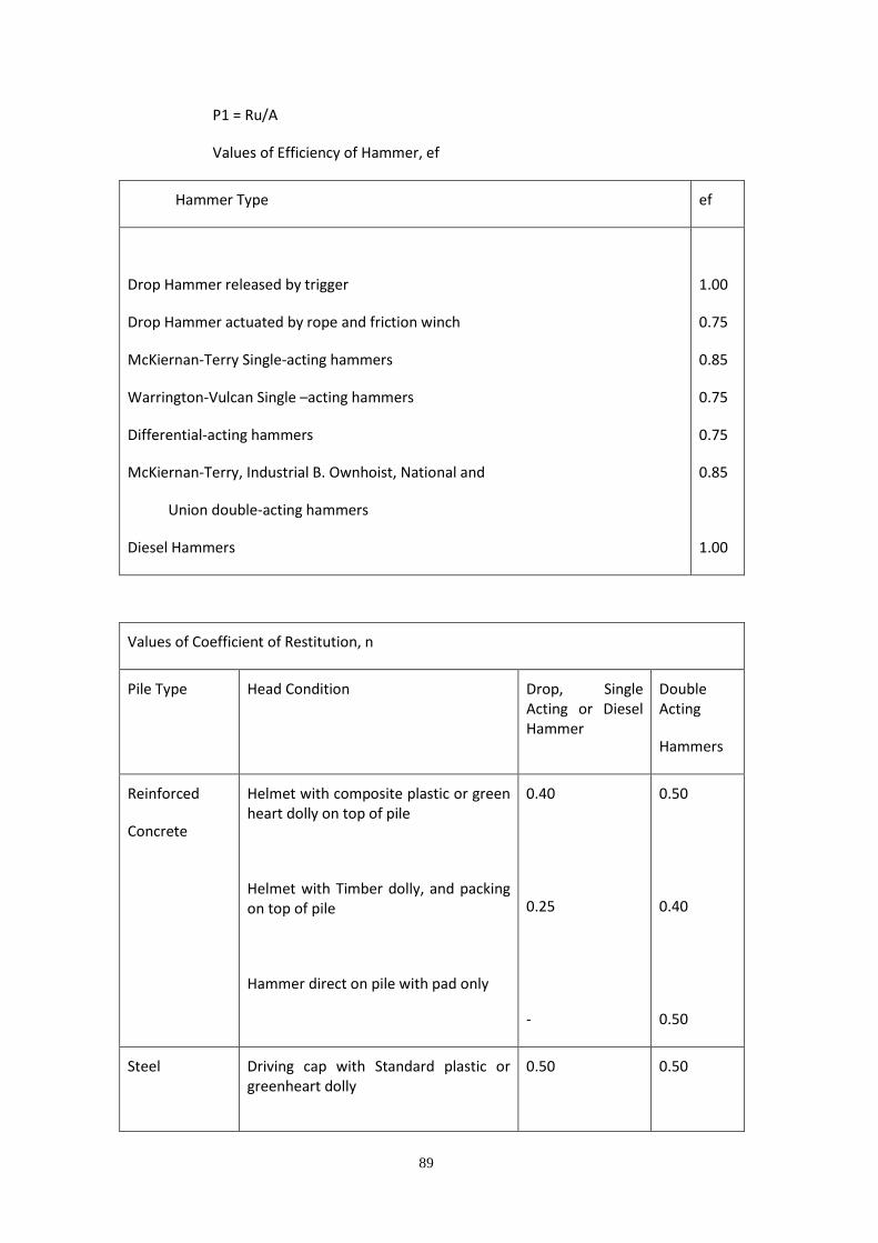
P1 = Ru/A
Values of Efficiency of Hammer, ef
Hammer Type ef
Drop Hammer released by trigger
Drop Hammer actuated by rope and friction winch
McKiernan-Terry Single-acting hammers
Warrington-Vulcan Single –acting hammers
Differential-acting hammers
McKiernan-Terry, Industrial B. Ownhoist, National and
Union double-acting hammers
Diesel Hammers
1.00
0.75
0.85
0.75
0.75
0.85
1.00
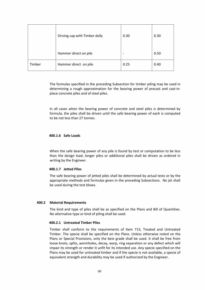
Values of Coefficient of Restitution, n
Pile Type Head Condition Drop, Single Acting or Diesel Hammer
Double Acting
Hammers
Reinforced
Concrete
Helmet with composite plastic or green heart dolly on top of pile
Helmet with Timber dolly, and packing on top of pile
Hammer direct on pile with pad only
0.40
0.25
-
0.50
0.40
0.50
Steel Driving cap with Standard plastic or greenheart dolly
0.50
0.50
90
Driving cap with Timber dolly
Hammer direct on pile
0.30
-
0.30
0.50
Timber Hammer direct on pile 0.25 0.40
The formulas specified in the preceding Subsection for timber piling may be used in determining a rough approximation for the bearing power of precast and cast-in-place concrete piles and of steel piles.
In all cases when the bearing power of concrete and steel piles is determined by formula, the piles shall be driven until the safe bearing power of each is computed to be not less than 27 tonnes.
400.1.6 Safe Loads
When the safe bearing power of any pile is found by test or computation to be less than the design load, longer piles or additional piles shall be driven as ordered in writing by the Engineer.
400.1.7 Jetted Piles
The safe bearing power of jetted piles shall be determined by actual tests or by the appropriate methods and formulas given in the preceding Subsections. No jet shall be used during the test blows.
400.2 Material Requirements
The kind and type of piles shall be as specified on the Plans and Bill of Quantities. No alternative type or kind of piling shall be used.
400.2.1 Untreated Timber Piles
Timber shall conform to the requirements of Item 713, Treated and Untreated Timber. The specie shall be specified on the Plans. Unless otherwise noted on the Plans or Special Provisions, only the best grade shall be used. It shall be free from loose knots, splits, wormholes, decay, warp, ring separation or any defect which will impair its strength or render it unfit for its intended use. Any specie specified on the Plans may be used for untreated timber and if the specie is not available, a specie of equivalent strength and durability may be used if authorized by the Engineer.
91
Round piles shall be cut above the ground swell and shall taper from butt to tip. A line drawn from the center of the tip to the center of the butt shall not fall outside of the cross-section of the pile at any point more than one percent of the length of the pile.
In short bends, the distance from the center of the pile to a line stretched from the center of the pile above the bend to the center of the pile below the bend shall not exceed four percent of the length of the bend or a maximum of 65mm.
Unless otherwise specified, all piles shall be peeled removing all rough bark and at least 80 percent of the inner bark. Not less than 80 percent of the surface on any circumference shall be clean wood. No strip of inner bark remaining on the pile shall be more than 20mm wide and 200mm long. All knots shall be trimmed close to the body of the pile.
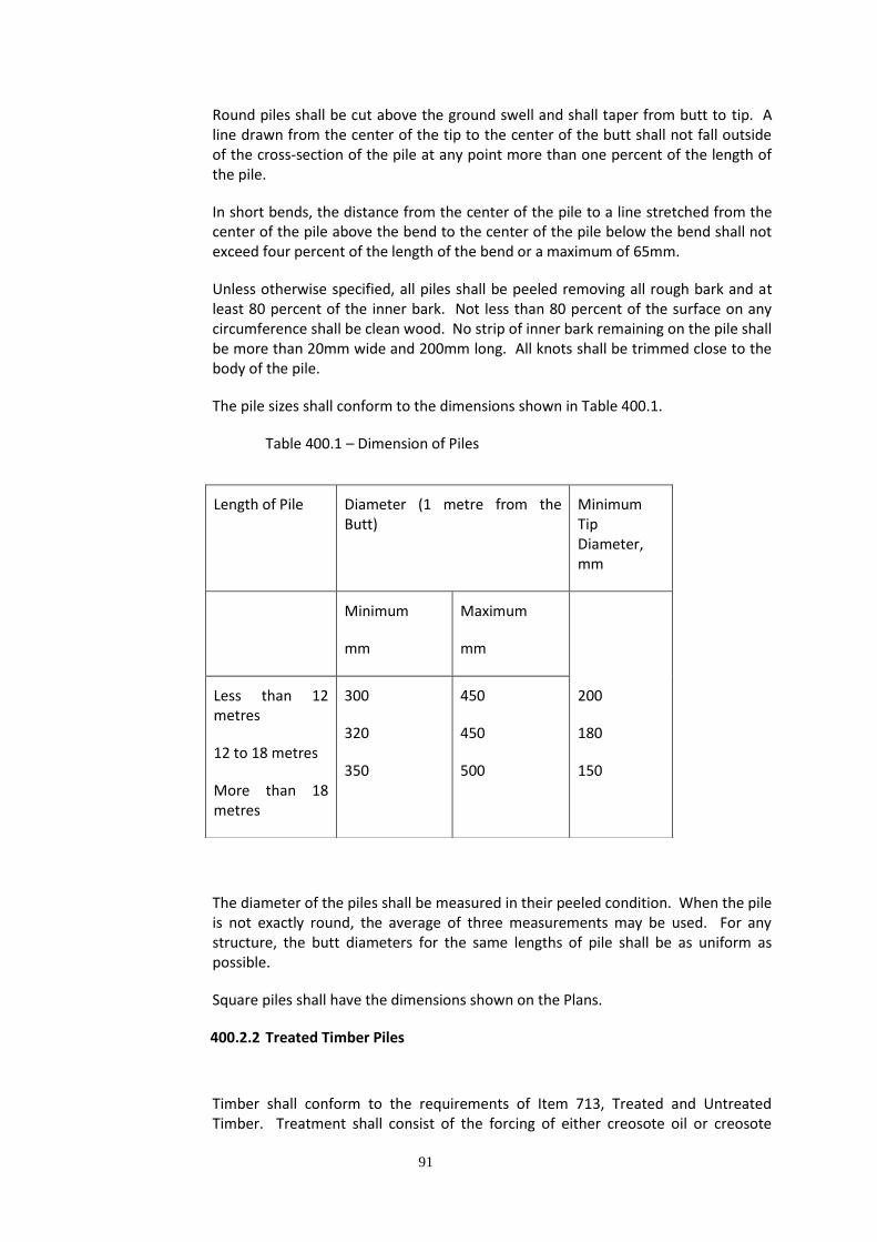
The pile sizes shall conform to the dimensions shown in Table 400.1.
Table 400.1 – Dimension of Piles
The diameter of the piles shall be measured in their peeled condition. When the pile is not exactly round, the average of three measurements may be used. For any structure, the butt diameters for the same lengths of pile shall be as uniform as possible.
Square piles shall have the dimensions shown on the Plans.
400.2.2 Treated Timber Piles
Timber shall conform to the requirements of Item 713, Treated and Untreated Timber. Treatment shall consist of the forcing of either creosote oil or creosote
Length of Pile Diameter (1 metre from the Butt)
Minimum Tip Diameter, mm
Minimum
mm
Maximum
mm
Less than 12 metres
12 to 18 metres
More than 18 metres
300
320
350
450
450
500
200
180
150

92
petroleum oil mixture into the outer fibers of the timber by a heat and pressure process. The process shall be in accordance with ASTM D-1760 Standard Specification for Pressure Treatment of Timber Products, but with such changes as temperatures, pressures, duration of treatment and other factors affecting the final treatment that experience has shown to be necessary in the treatment of structural timbers sawn from woods native to the Philippines. The treatment shall be so regulated that the curing process will not induce excessive checking. The minimum penetration of the preservative into the surface of the timber shall be 20 mm. All piles shall retain the minimum amount of preservative specified in Table 400.2.
Table 400.2 – Minimum Preservative Per Cubic Metre of Wood
The Engineer shall inspect the timber prior to the treatment to determine conformance with the Specifications and suitability of conditions for treatment. He shall be permitted free access to the plant in order that temperatures, pressures and quantities and type of treatment materials used may be observed. Samples of the creosote or creosote petroleum mixtures shall be furnished as required for test.
The timber shall be checked to determine penetration of treatment, quantity of free preservative remaining on the timber and any visual evidence that the treatment has been performed in a satisfactory manner. The penetration of treatment shall be determined by boring a sufficient number of well-distributed holes to determine the average penetration. All such holes shall be plugged with plugs approximately 2 mm larger in diameter than the bit used in boring the holes.
If the penetration of preservative is less than the required amount, the entire charge, or such parts thereof shall be retreated. If after treatment the penetration is still insufficient, the treated pieces shall be rejected.
400.2.3 Concrete Piles
Concrete shall conform to the requirements of Item 405, Structural Concrete. Concrete shall be Class “C” unless otherwise specified in the Plans.
Concrete shall be proportioned to achieve a range of 6”-8” (150 mm to 200 mm) slump, self-compacting mix.
The use of appropriate plasticizer/additives to assure mix fluidity and consistency shall be allowed and with the Engineer’s approval. A retardant of proven adequacy
Type of Processing
Use Empty Cell Process Full Cell Process
General Use
Marine Use
195 kg
320 kg

93
and approved by the Engineer may be used to ensure that early hardening of concrete during operation will not occur.
Reinforcing steel shall conform to the requirements of Item 404, Reinforcing Steel. Prestressing reinforcing steel shall be high-tensile steel wire conforming to AASHTO M 204 or other high-tensile metals conforming to AASHTO Standards.
400.2.4 Steel Shells
1. Shells Driven Without a Mandrel
Unless otherwise called for on the Plans or Special Provisions, shells for cast-in-place concrete piles shall have a minimum 305mm diameter at cut off and a minimum 203mm diameter at tip: made from not less than 4.55mm in thickness plate stock conforming to AASHTO M 183. Shells may either be spirally welded or longitudinally welded and may either be tapered or constant in section. Tips shall be sealed as shown on the Plans.
2. Shells Driven With a Mandrel
The shell shall be of sufficient strength and thickness to withstand driving without injury and to resist harmful distortion and/or buckling due to soil pressure after driven and the mandrel removed. Butt and tip dimension shall be as called for on the Plans or Special Provisions.
400.2.5 Steel Pipes
Filled Steel Pipes (filled with concrete) shall conform to the requirements of ASTM A 252, Grade 2, Welded and Seamless Pipe Piles. Closure Plates for closed piles shall conform to the requirements of AASHTO M 183.
Unfilled Tubular Steel Piles shall conform to the requirements of ASTM A 252, Grade 2, with chemical requirements meeting ASTM Designation A 53, Grade B. The wall thickness shall not be less than 4.76mm.
400.2.6 Steel H-Piles
Steel H-Piles shall be rolled steel sections of the weight and shape called for on the Plans. They shall be structural steel meeting the requirements of AASHTO M 183 provided that, where the Special Provisions called for copper-bearing structural steel, the steel shall not contain less than one-fifth percent nor more than zero point thirty five percent (0.35%) of copper, except that steel manufactured by the acid-bessemer process shall not be used.
400.2.7 Sheet Piles
Steel sheet piles shall meet the requirements of AASHTO M 202 (ASTM A 328), or AASHTO M 223. All other sheet piles shall meet the requirements prescribed above the particular material specified. The joints shall be practically water-tight when the piles are in place.

94
400.2.8 Pile Shoes
Pile shoes shall be as called for on the Plans.
400.2.9 Splices
Material for pile splices, when splicing is allowed, shall be of the same quality as the material used for the pile itself and shall follow the requirements given on the Plans.
400.2.10 Paint
It shall conform to Item 709, Paints.
400.3 Construction Requirements
400.3.1 Location and Site Preparation
Piles shall be driven where indicated on the Plans or as directed by the Engineer.
All excavations for the foundation on which the piles are to be driven shall be completed before the pile driving, unless otherwise specified or approved by the Engineer. After driving is completed, all loose and displaced materials shall be removed from around the piles by hand excavation, leaving clean solid surface to receive the concrete of the foundation. Any requirement for granular fill and lean concrete shall be indicated on the Plans or as directed by the Engineer.
400.3.2 Determination of Pile Length
Pile length and bearing capacity shall be determined by the Engineer from the results of the test piling and load tests.
The criterion for pile length may be one of the following:
1. Piles in sand and gravel shall be driven to a bearing power determined
by the use of the pile driving formula or as decided by the Engineer. 2. Piles in clay shall be driven to the depth ordered by the Engineer.
However, the bearing power shall be controlled by the pile driving formula if called for by the Engineer.
3. Piles shall be driven to refusal on rock or hard layer when so ordered by the Engineer.
The Contractor shall be responsible for obtaining the correct pile length and bearing capacity according to the criteria given by the Engineer.
95
400.3.3 Pile Driving
All piles shall be driven as shown on the Plans or as ordered in writing by the Engineer. They shall be driven within an allowed variation of 20mm per metre of pile length from the vertical or batter as shown on the Plans. The maximum allowable variation at the butt end of the pile shall be 75mm in any direction from the location shown on the Plans or as directed by the Engineer. Each pile shall, after driving, be within 150mm from the theoretical location underneath the pile cap or underneath the superstructure in case of pile bents. All piles pushed up by the driving of adjacent piles or any other cause shall be redriven.
Piles shall be used only in places where the minimum penetration of 3m in firm materials, or 5m in soft materials can be obtained. Whereas soft upper stratum overlies a hard stratum, the piles shall penetrate the hard materials at sufficient depths to fix the ends rigidly.
All pile driving equipment is subject to the Engineer’s approval. The Contractor is responsible for sufficient weight and efficiency of the hammers to drive the piles down to the required depth and bearing capacity. Hammers shall be gravity hammers, single and double acting steam or pneumatic hammers or diesel hammers. Gravity hammers shall not weigh less than 60 percent of the combined weight of the pile and driving head but not less than 2,000 kg. The fall shall be regulated so as to avoid injury to the pile and shall in no case exceed 4.50m for timber and steel piles and 2.50m for concrete piles unless otherwise specified or approved by the Engineer.
The plant and equipment furnished for steam hammers shall have sufficient capacity to maintain, under working condition, the pressure at the hammer specified by the manufacturer. The boiler or pressure tank shall be equipped with an accurate pressure gauge and another gauge shall be supplied at the hammer intake to determine the drop in pressure between the gauges. When diesel hammers or any other types requiring calibration are used, they shall be calibrated with test piling and/or test loads in accordance with Subsection 400.1.2, Test Piles.
Water jets shall be used only when permitted in writing by the Engineer. When water jets are used, the number of jets and the nozzle volume and pressure shall be sufficient to erode freely the material adjacent to the pile. The plant shall have sufficient capacity to deliver at all time a pressure equivalent to at least 690 KPa at two 19 mm (3/4 inch) jet nozzles. The jets shall be shut off before the required penetration is reached and the piles shall be driven solely by hammers to final penetration as required by the Engineer.
Piles shall be supported in line and position with leads while being driven. Pile driving leads shall be constructed in such a manner as to afford freedom of movement of the hammer, and shall be held in position by guys or steel braces to insure rigid lateral support to the pile during driving. The leads shall be of sufficient length to make the use of a follower unnecessary and shall be so designed as to permit proper placing of batter piles. The driving
96
of the piles with followers shall be avoided if practicable and shall be done only under written permission from the Engineer.
The method used in driving piles shall not subject them to excessive and undue abuse producing crushing and spalling of the concrete, injurious splitting, splintering and brooming of the wood or deformation of the steel. Manipulation of piles to force them into proper position if considered by the Engineer too excessive will not be permitted.
The pile tops shall be protected by driving heads, caps or cushions in accordance with the recommendation of the manufacturer of the pile hammer and to the satisfaction of the Engineer. The driving head shall be provided to maintain the axis of the pile with the axis of the hammer and provide a driving surface normal to the pile.
Full length piles shall be used where practicable. Splicing of piles when permitted, shall be in accordance with the provisions of Subsection 400.3.7 and 400.3.8. All piles shall be continuously driven unless otherwise allowed by the Engineer.
Piles shall not be driven within 7 m of concrete less than 7 days old.
400.3.4 Timber Piles
Piles shall be strapped with three metal straps: one about 450mm from the butt, one about 600mm from the butt, and the third, about 300mm from the tip. Additional straps shall be provided at about 4.5m on centers between tip and butt. Strapping should encircle the pile once and be tensioned as tightly as possible. Straps shall be 38mm wide, 0.8mm thick, cold rolled, fully heat treated, high tensile strapping, painted and waxed.
Treated piles shall be strapped after treatment.
Point protection shall be considered for all timber piles. Where timber piles must penetrate dump fill, or may encounter obstructions or be driven to hard strata, point protection shall be used. A boot that encompasses and utilizes the entire end area of the pile is preferred.
400.3.5 Timber Pile Bents
Piles for any one bent shall be carefully selected as to size, to avoid undue bending or distortion of the sway bracing. Care shall be exercised in the distribution of piles of various sizes to obtain uniform strength and rigidity in the bents of any given structure.
Cut offs shall be made accurately to insure full being between caps and piles of bents.
400.3.6 Precast Concrete Piles
Precast concrete piles shall be of the design shown on the Plans. Prestressed concrete piles shall be prestressed as prescribed in Item 406,

97
Prestressed Concrete Structures. The piles shall be cast separately and concrete in each pile shall be place continuously. The completed piles shall be free from stone pockets, honeycombs, or other defects, and shall be straight and true to the form specified. The forms shall be true to line and built of metal, plywood or dressed lumber. A 25mm chamfer strip shall be used in all corners. Form shall be water-tight and shall not be removed until at least twenty-four (24) hours after the concrete is placed.
Piles shall be cured and finished in accordance with Items 405, Structural Concrete and 406, Prestressed Concrete Structures.
Cylinder specimens shall be made and tested in accordance with Item 405. Piles shall not be moved until the tests indicate that the concrete has attained a compressive strength of at least 80 percent (80%) of the design 28-day compressive strength and they shall not be transported or driven until the design 28-day compressive strength has been attained.
If testing equipment is not available, as in isolated areas, piles shall not be moved until after fourteen (14) days after casting and shall not be transported or driven prior to 28 days after casting. If high early strength cement is used, piles shall not be moved, transported or driven prior to 7 days after casting.
When concrete piles are lifted or moved, they shall be supported at the points shown on the Plans; if not shown, they shall be supported at the quarter points.
400.3.7 Cast-in-place Concrete Piles
1. Drilled Holes
All holes for concrete piles cast in drilled holes shall be drilled dry to tip elevation shown on the Plans. All holes will be examined for straightness and any hole which on visual inspection from the top shows less than one-half the diameter of the hole at the bottom of the hole will be rejected. Suitable casings shall be furnished and placed when required to prevent caving of the hole before concrete is placed.
All loose material existing at the bottom of the hole after drilling operations have been completed shall be removed before placing concrete.
The use of water for drilling operations or for any other purpose where it may enter the hole will not be permitted. All necessary action shall be taken to prevent surface water from entering the hole and all water which may have infiltrated into the hole shall be removed before placing concrete.
98
Concrete shall be placed by means of suitable tubes. Prior to the initial concrete set, the top 3m of the concrete filled pile or the depth of any reinforcing cage, whichever is greater, shall be consolidated by acceptable vibratory equipment,
Casing, if used in drilling operations, may be left in place or removed from the hole as concrete is placed. The bottom of the casing shall be maintained not more than 1.5m nor less than 0.3m below the top of the concrete during withdrawal and placing operations unless otherwise permitted by the Engineer. Separation of the concrete during withdrawal operations shall be avoided by vibrating the casing.
2. Steel Shells and Pipes
The inside of shells and pipes shall be cleaned and all loose materials removed before concrete is placed. The concrete shall be placed in one continuous operation from tip to cut-off elevation and shall be carried on in such a manner as to avoid segregation.
The top 3m of concrete filled shells, or to the depth of any reinforcing cage, whichever is greater, shall be consolidated by acceptable vibratory equipment.
Pipes shall be of the diameter shown on the Plans. The pipe wall thickness shall not be less than that shown on the Plans but in no case less than 5mm. The pipe, including end closures, shall be of sufficient strength to be driven by the specified methods without distortion.
Closure plates and connecting welds shall not project more than 12.5mm beyond the perimeter of the pile tips.
No shell or pipe shall be filled with concrete until all adjacent shells, pipes, or piles within a radius of 1.5m or 4 ½ times the average pile diameter, whichever is greater, have been driven to the required resistance.
After a shell or pipe has been filled with concrete, no shell, pipe or pile shall be driven within 6m thereof until at least 7 days have elapsed.
3. Drilled Shafts
Drilled shafts are deep foundations formed by boring a cylindrical hole into soil and/or rock and filling the hole with concrete. Drilled shafts are also commonly referred to as caissons, bored piles or drilled piers.
99
Drilled shafts, like driven piles, transfer structural loads to bearing stratum well below the base of the structure by passing soils having insufficient strength to carry the design loads.
Drilled shafts are classified according to their primary mechanism for deriving load resistance either as floating shafts (i.e., shafts transferring load primarily by side resistance), or end-bearing shafts (i.e., shafts transferring load primarily by tip resistance). Occasionally, the bases of shafts are enlarged (i.e., belled or underreamed) to improved the load capacity of end bearing shafts on less than desirable soils, or to increase the uplift resistance of floating shafts.
Effects of ground and ground water conditions on shaft construction operations should be considered and delineated, when necessary, the general method of construction to be followed to ensure the expected performance. Because shafts derive their capacity from side and tip resistance which are a function of the condition of the materials in direct contact with the shaft, it is important that the construction procedures be consistent with the material conditions assumed in the design. Softening, loosening or other changes in soil and rock conditions caused by the construction method could result in a reduction in shaft capacity and an increase in shaft displacement. Therefore, evaluation of the effects of shaft construction procedure on load capacity must be considered an inherent aspect of the design.
Drilled shafts are normally sized in 15.24cm (6-inch diameter increments with a minimum diameter of 45.72cm (18”). The diameter of a shaft socketed into rock should be a minimum of 15.24cm (6”) larger than the socket diameter. If a shaft must be inspected by the entry of a person, the shaft diameter shall not be less than 76.20cm (30”).
Drilled shafts constructed in dry, noncaving soils can usually be excavated without lateral support of the hole. Other ground conditions where caving, squeezing or sloughing soils are present require installation of a steel casing or use of a slurry for support of the hole. Such conditions and techniques may result in loosening of soil around the shaft, or altering of frictional resistance between the concrete shaft and surrounding soil.
The center-to-center spacing between shafts is normally restricted to a minimum of 3B to minimize the effects of interaction between adjacent shafts during construction or in service. However, larger spacings may be required where drilling operations are difficult or where construction must be completed in very short time frames.
Particular attention should be given to the potential for deposition of loose or wet material in the bottom of the hole, or the buildup of a cake of soft material around the shaft perimeter prior to concrete placement. Adequate cleaning and inspection of rock sockets should always be performed to assure good contact between the

100
rock and shaft concrete. If good contact along the shaft cannot be confirmed, it may be necessary to assume that all load is transferred to the tip. If the deposition of soft or loose material in the bottom of the hole is expected, the shaft may have to be designed to carry the entire design load through side resistance.
A number of methods can be used to prevent caving during the drilling of holes and the placement of concrete. It is preferred that drilled shafts be constructed in stable non-sloughing soil without excessive ground water. If impossible, consider the following three different construction methods:
a. The construction of the pile or shaft in a wet condition while the walls of the excavation are stabilized by hydrostatic pressure of water or a mineral slurry until the concrete is placed by tremie methods for the full length of the pile.
Mineral slurry used in the drilling process shall have both a mineral grain size that will remain in suspension and sufficient viscosity and gel characteristics to transport excavated material to a suitable screening system. The percentage and specific gravity of the material used to make the suspension shall be sufficient to maintain the stability of the excavation and to allow proper concrete placement. The level of the slurry shall be maintained at a height sufficient to prevent caving of the hole.
The mineral slurry shall be premixed thoroughly with clean fresh water and adequate time allotted for hydration prior to introduction into the shaft excavation. Adequate slurry tanks will be required when specified. No excavated slurry pits will be allowed when slurry tanks are required on the project without written permission of the Engineer. Adequate desanding equipment will be required when specified. Steps shall be taken as necessary to prevent the slurry from “setting up” in the shaft excavation, such as agitation, circulation, and adjusting the properties of the slurry.
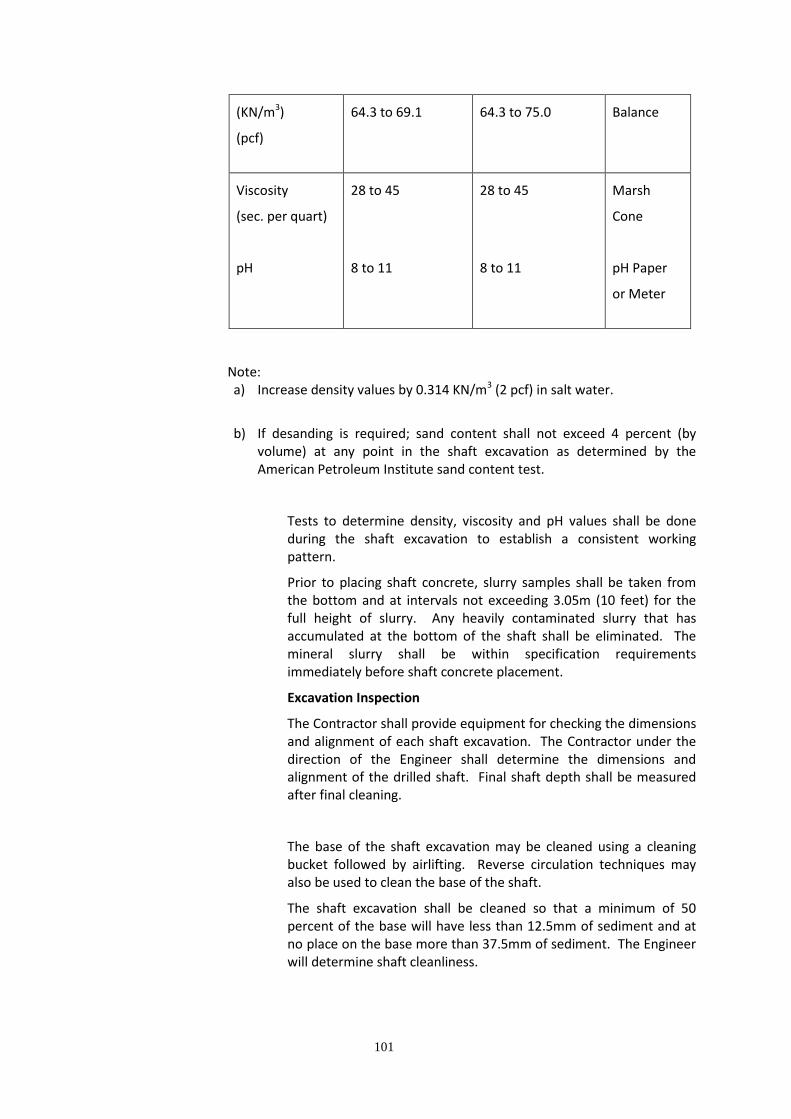
Control tests using suitable apparatus shall be carried out by the Contractor on the mineral slurry to determine density, viscosity, and pH. An acceptable range of values for those physical properties is shown in the following table.
Range of Values (At 20o [68oF])
Property
(Units)
Time of Slurry
Introduction
Time of Concreting
(In Hole)
Test
Method
Density 10.10 to 10.86 10.10 to 11.79 Density
101
(KN/m3)
(pcf)
64.3 to 69.1 64.3 to 75.0 Balance
Viscosity
(sec. per quart)
pH
28 to 45
8 to 11
28 to 45
8 to 11
Marsh
Cone
pH Paper
or Meter
Note: a) Increase density values by 0.314 KN/m3 (2 pcf) in salt water.
b) If desanding is required; sand content shall not exceed 4 percent (by
volume) at any point in the shaft excavation as determined by the American Petroleum Institute sand content test.
Tests to determine density, viscosity and pH values shall be done during the shaft excavation to establish a consistent working pattern.
Prior to placing shaft concrete, slurry samples shall be taken from the bottom and at intervals not exceeding 3.05m (10 feet) for the full height of slurry. Any heavily contaminated slurry that has accumulated at the bottom of the shaft shall be eliminated. The mineral slurry shall be within specification requirements immediately before shaft concrete placement.
Excavation Inspection
The Contractor shall provide equipment for checking the dimensions and alignment of each shaft excavation. The Contractor under the direction of the Engineer shall determine the dimensions and alignment of the drilled shaft. Final shaft depth shall be measured after final cleaning.
The base of the shaft excavation may be cleaned using a cleaning bucket followed by airlifting. Reverse circulation techniques may also be used to clean the base of the shaft.
The shaft excavation shall be cleaned so that a minimum of 50 percent of the base will have less than 12.5mm of sediment and at no place on the base more than 37.5mm of sediment. The Engineer will determine shaft cleanliness.
102
b. The use of steel casing which is installed during drilling operations to hold the hole open and usually withdrawn during concrete placement.
Casing, if used in operation, shall be metal, smooth, clean, watertight, and of ample strength to withstand both handling and driving stresses and the pressure of both concrete and the surrounding earth materials. The outside diameter of casing shall not be less than the specified size of the shaft. It shall conform to AASHTO M 270 (ASTM A 709) Grade 36 unless otherwise specified.
Temporary casings shall be removed while the concrete remains workable. Generally the removal of temporary casing shall not be started until concrete placement in the shaft is at or above ground surface. Movement of casing by rotating, exerting downward pressure and tapping to facilitate extraction or extraction with a vibratory hammer will be permitted. Casing extraction shall be at a slow, uniform rate with the pull in line with the shaft axis.
A sufficient head of concrete shall be maintained above the bottom of the casing to overcome the hydrostatic pressure of water or drilling fluid outside of the casing.
c. The use of a permanent casing which is left in place within the portion of the pile which is in unstable material.
A permanent casing is applied as protection from the presence of surface water during drilling and as support later for the installation of the rebar cage and as a concrete form in drilling under water.
Reinforcing Steel Cage Construction and Placement
The reinforcing steel cage consisting of the steel shown on the Plans plus cage stiffener bars, spacers, centralizers and any other necessary appurtenances shall be completely assembled and placed as a unit immediately after the shaft excavation is inspected and accepted and prior to shaft concrete placement.
Where the reinforcing cage length is too long for placement as a single unit the cage may be placed in separate units such that appropriate means of splicing the longitudinal steel is provided for. The Contractor shall submit his plans for such splices to the Engineer for approval.

103
The reinforcing steel in the hole shall be tied and supported so that the reinforcing steel will remain within allowable tolerances until the concrete will support the reinforcing steel. When concrete is placed by suitable tubes, temporary hold-down devices shall be used to prevent uplifting of the steel cage during concrete placement. Concrete spacers or other approved noncorrosive spacing devices shall be used at sufficient intervals not exceeding 1.50 meters along the shaft to insure concentric location of the cage within the shaft excavation. When the size of the longitudinal reinforcing steel exceeds 25mm, such spacing shall not exceed 3.0 meters.
Concrete Placement, Curing and Protection
Concrete shall be placed as soon as possible after reinforcing steel cage placement. Concrete placement shall be continuous in the shaft to the top elevation of the shaft. Placement shall continue after the shaft is full until good quality concrete is evident at the top of the shaft. Concrete shall be placed through a suitable tube.
For piles less than 2.5 meters in diameter, the elapsed time from the beginning of concrete placement in the shaft to the completion of placement shall not exceed 2 hours. For piles 2.50 meters and greater in diameter, the concrete placing rate shall not be less than 9.0 meters of pile height per each 2-hour period. The concrete mix shall be of such design that the concrete remains in a workable plastic state throughout the 2-hour placement limit.
When the top of pile elevation is above ground, the portion of the pile above ground shall be formed with a removable form or permanent casing when specified.
The upper 1.5 meters of concrete shall be vibrated or rodded to a depth of 1.5 meter below the ground surface except where soft uncased soil or slurry remaining in the excavation will possibly mix with the concrete.
After placement, the temporarily exposed surfaces of the shaft concrete shall be cured in accordance with the provision in Sub-section 407.3.8 – Curing Concrete.
For at least 48 hours after pile concrete has been placed, no construction operations that would cause soil movement adjacent to the shaft, other than mild vibration, shall be conducted.
Construction Tolerances:
The following tolerances shall be maintained in constructing drilled shaft.
a. The drilled shaft shall be within 7.62cm (6”) of the plan position in the horizontal plane at the plan elevation for the top of the shaft.

104
b. The vertical alignment of the shaft excavation shall not vary
from the plan alignment by more than 20.83 mm/m (1/4 inch per foot) of depth.
c. After all the shaft concrete is placed, the top of the
reinforcing steel cage shall be no more than 15.24 cm (6”) above and no more than 7.62 cm (3”) below plan position.
d. When casing is used, its outside diameter shall not be less
than the shaft diameter shown on the plans. When casing is not used, the minimum diameter of the drilled shaft shall be the diameter shown on the plans for diameters 60.96 cm (24”) or less, and not more than 2.54 cm (1 inch) less than the diameter shown on the plans for diameters greater than 60.96 cm (24”).
e. The bearing area of bells shall be excavated to the plan
bearing area as a minimum. All other plan dimensions shown for the bells may be varied, when approved, to accommodate the equipment used.
f. The top elevation of the shaft shall be within 2.54 cm (1
inch) of the plan top of shaft elevation.
g. The bottom of the shaft excavation shall be normal to the
axis of the shaft within 62.5 mm/m (3/4 inch per foot) of shaft diameter.
Drilled shaft excavations constructed in such a manner that the concrete shaft cannot be completed within the required tolerances are unacceptable.
400.3.8 Steel H-Pile
Steel H-Pile shall consist of structural steel shapes of the sections indicated on the Plans.
When placed in the leads, the pile shall not exceed the camber and sweep permitted by allowable mill tolerance. Piles bent or otherwise damaged will be rejected.
The loading, transporting, unloading, storing and handling of steel H-pile shall be conducted so that the metal will be kept clean and free from damage.
400.3.9 Unfilled Tubular Steel Piles
The tubular steel piles should be or as specified by the Engineer.

105
The minimum wall thickness shall be as indicated in the following table:
Cutting shoes for piles driven open end may be inside or outside of the pipe. They may be high carbon structural steel with a machined ledged for pile bearing or cast steel with a ledge, designed for attachment with a simple weld.
400.3.10 Splicing
Splicing when permitted shall be made as shown on the Plans and in accordance with this Subsection.
1. Precast Concrete Piles
a. By using prefabricated joints mounted in the forms and cast together with the piles sections and joined together as specified by the manufac-turer and approved by the Engineer. The joints shall be of the design and type as specified or shown on the Plans.
b. By cutting away the concrete at the end of the pile, leaving the reinforcing steel exposed for a length of 40 bar diameters for corrugated or deformed bars and 60 bar diameters for plain bars. The final cut of the concrete shall be perpendicular to the axis of the pile. Reinforcement of the same size as that used in the pile shall be spliced to the projecting steel in accordance with Item 404, Reinforcing Steel, and the necessary formwork shall be placed, care being taken to prevent leakage along the pile. The concrete shall be of the same quality as that used in the pile. Just prior to placing concrete, the top of the pile shall be wetted thoroughly and covered with a thin coating of neat cement, retempered mortar, or other suitable bonding material to the satisfaction of the Engineer. The forms shall remain in place not less than seven (7) days. The pile shall not be driven until the safe design has been reached.
c. By any other method shown on the Plans or approved by
the Engineer. Curing and finishing of extensions shall be the same as in the original pile.
2. Prestressed Piles
Splicing of prestressed precast piles will generally not be permitted, but when permitted, it shall be made in accordance
Outside Diameter
Less than 355 mm 355 mm and over
Minimum wall thickness
6.5 mm 9.5 mm

106
with (1) above, but only after driving has been completed. Reinforcement bars shall be included in the pile head for splicing to the extension bars. No additional driving will be permitted. The Contractor, at his option, may submit alternative plans of splicing for consideration by the Engineer.
3. Steel Piles, Shells or Pipes
If the length of the steel pile, shell or pipe driven is insufficient to obtain the specified bearing power, an extension of the same cross-section shall be spliced to it. Unless otherwise shown on the Plans, splices shall be made by butt-welding the entire cross-sections to form an integral pile using the electric arc method. The sections connected shall be properly aligned so that the axis of the pile shall be straight. Bent and/or damaged piles shall be rejected.
400.3.11 Cutting Off and Capping Piles
The top of foundation piles shall be embedded in the concrete footing as shown on the Plans.
Concrete piles shall, when approved by the Engineer, be cut off at such a level that at least 300mm of undamaged pile can be embedded in the structure above. If a pile is damaged below this level, the Contractor shall repair the pile to the satisfaction of the Engineer. The longitudinal reinforcement of the piles shall be embedded in the structure above to a length equal to at least 40 times the diameter of the main reinforcing corrugated bars (60 diameters for plain bars). The distance from the side of any pile to the nearest edge of the cap shall not be less than 200mm.
When the cut off elevation for a precast pile or for the steel shell or pile for a cast in place concrete pile is below the elevation of the bottom of the pile cap, the pile may be built-up from the butt of the pile to the elevation of the bottom of the cap by means of reinforced concrete extension constructed in accordance with Subsection 400.3.10 or as approved by the Engineer.
Cut-offs of structural steel piles shall be made at right angles to the axis of the pile. The cuts shall be made in clear, straight lines and any irregularity due to cutting or burning shall be leveled-off with deposits of weld metal prior to placing bearing caps.
400.3.12 Defective Piles
Any pile delivered with defects, or damaged in driving due to internal defects or by improper driving, or driven out of its proper location, or driven below the elevation fixed by the Plans or by the Engineer, shall be corrected at the Contractor’s expense by one of

107
the following methods approved by the Engineer for the pile in question:
1. Any pile delivered with defects shall be replaced by a new pile.
2. Additional pile shall be driven/casted at the location as directed
by the Engineer.
3. The pile shall be spliced or built-up as otherwise provided herein
on the underside of the footing lowered to properly embed the pile.
A precast concrete pile shall be considered defective if it has a visible crack, extending around the four sides of the pile, or any defect which, in the opinion of the Engineer, affects the strength or life of the pile.
When a new pile is driven or cast to replace a rejected one, the Contractor at his own expense, shall enlarge the footing as deemed necessary by the Engineer.
400.3.13 Protecting Untreated Timber Trestle Piles
The heads of untreated piles shall be treated as follows:
The sawed surface shall be thoroughly brush-coated with two (2) applications of hot creosote oil or other approved preservative.
400.3.14 Protecting Treated Timber Trestle Piles
All cuts and abrasions in treated timber piles shall be protected by a preservative approved by the Engineer.
400.3.15 Painting Steel Piles
Unless otherwise provided, when required steel piles extend above the ground surface or water surface, they shall be protected by paint as specified for cleaning and painting metal surfaces in accordance with Item 403, Metal Structures. This protection shall extend from the elevation shown on the Plans to the top of the exposed steel.
400.3.16 Pile Records
The Contractor shall keep records of all piles driven or installed. A copy of the record shall be given to the Engineer within two (2) days after each pile is driven. The record form to be used shall be approved by the Engineer. The pile records shall give full information on the following:

108
Driven Piles Cast-in-Place Piles
1. Pile type and dimension
2. Date of casting and concrete
quality (for concrete piles)
3. Date of driving
4. Driving equipment: type,
weight & efficiency of hammer,
etc.
5. Description of cushion on pile
head
6. Depth driven and tip elevation
7. Final set for the last 20 blows (for every 10 piles and when the Engineer so requires the
penetration along the whole
depth driven shall be recorded)
8. For gravity and single-acting
1. Date of boring or driving (For steel shell) & casting
2. Pile type and nominal dimension
3. Length of finished pile and tip elevation
4. Details of penetration during
boring or driving of steel shell
(driving records as for driven
piles)
5. Concrete quality and consis-
tency
6. Time interval between boring
or driving and concreting
7. Volume of concrete placed in
concrete

109
400.4 Method of Measurement
400.4.1 Timber, Steel and Precast Concrete Piles
1. Piles Furnished
The quantity to be paid for will be the sum of the lengths in metres of the piles of the several types and lengths ordered in writing by the Engineer, furnished in compliance with these Specifications and stockpiles in good condition at the project site by the Contractor and accepted by the Engineer. The length to be paid for will include test and tension piles ordered by the Engineer, but not those furnished by the Contractor at his option. No allowance will be made for piles, including test piles, furnished by the Contractor to replace piles previously accepted by the Engineer that are subsequently lost or damaged while in stockpile, or during handling or driving, and are ordered by the Engineer to be removed from the site of work.
In case extensions of piles are necessary, the extension length will be included in the length of pile furnished, except for cut off lengths used for extensions and already measured for payment.
hammers: the height of drop
9. For double acting-hammers ---
the frequency of blows
10. Details of any interruption in
driving
11. Level of pile top immediately
after driving and the level
when all piles in the group are
driven
12. Details of re-driving

110
2. Piles Driven
The quantity to be paid for will be the sum of the lengths in metres of the piles driven in the completed work measured from the pile tip elevation to the bottom of pile caps, footings or bottom of concrete superstructure in the case of pile bents. Measurement will not include additional piles or test piles driven that may be necessary to suit the Contractor’s method of construction and were driven at his option.
Unless otherwise provided for, preboring, jetting or other methods used for facilitating pile driving operations will not be measured directly but will be considered subsidiary to pay items.
400.4.2 Cast-In-Place Concrete Piles
The quantity to be paid for will be the sum of actual lengths in meters of the piles cast and left in-place in the completed and accepted work. Measurements will be from the pile tip to the bottom of cap or footing. Portions of
piles cast deeper than the required length through over-drilling will not be measured for payment.
400.4.3 Pile Shoes
The quantity to be paid for, including test pile shoes, will be the number of pile shoes driven shown on the Plans or ordered in writing by the Engineer, furnished by the Contractor in accordance with these Specifications and accepted by the Engineer. Pile shoes furnished by the Contractor at his option or to replace those that are lost or damaged in stockpile or handling will not be measured for payment.
400.4.4 Load Tests
The quantity of the load tests to be paid for will be the number of tests completed and accepted except that load tests made to calibrate different types of hammers, if not included in the Bill of Quantities, will not be measured for payment.
Anchor and test piling which are not part of the completed structure, will be included in the unit bid price for each “Load Test”. Anchor and test piling or anchor and test shafts which are a part of the permanent structure will be paid for under the appropriate Item.
400.4.5 Splices
The quantity to be paid for will be the number of splices which may be required to drive the pile in excess of the estimated length shown on the Plans for cast-in-place steel pipes or shells or in excess of the order length furnished by the Engineer for all other types of piling. Splices
111
made for the convenience of the Contractor or to fabricate piles cut offs will not be paid for.
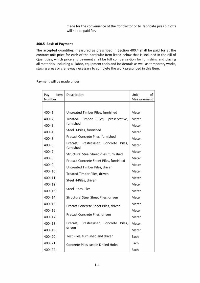
400.5 Basis of Payment
The accepted quantities, measured as prescribed in Section 400.4 shall be paid for at the contract unit price for each of the particular item listed below that is included in the Bill of Quantities, which price and payment shall be full compensa-tion for furnishing and placing all materials, including all labor, equipment tools and incidentals as well as temporary works, staging areas or craneway necessary to complete the work prescribed in this Item.
Payment will be made under:
Pay Item Number
Description Unit of Measurement
400 (1)
400 (2)
400 (3)
400 (4)
400 (5)
400 (6)
400 (7)
400 (8)
400 (9)
400 (10)
400 (11)
400 (12)
400 (13)
400 (14)
400 (15)
400 (16)
400 (17)
400 (18)
400 (19)
400 (20)
400 (21)
400 (22)
Untreated Timber Piles, furnished
Treated Timber Piles, preservative, furnished
Steel H-Piles, furnished
Precast Concrete Piles, furnished
Precast, Prestresssed Concrete Piles, furnished
Structural Steel Sheet Piles, furnished
Precast Concrete Sheet Piles, furnished
Untreated Timber Piles, driven
Treated Timber Piles, driven
Steel H-Piles, driven
Steel Pipes Piles
Structural Steel Sheet Piles, driven
Precast Concrete Sheet Piles, driven
Precast Concrete Piles, driven
Precast, Prestresssed Concrete Piles, driven
Test Piles, furnished and driven
Concrete Piles cast in Drilled Holes
Meter
Meter
Meter
Meter
Meter
Meter
Meter
Meter
Meter
Meter
Meter
Meter
Meter
Meter
Meter
Meter
Meter
Meter
Meter
Each
Each
Each

112
400 (23)
400 (24)
Concrete Piles cast in Steel Shells
Concrete Piles cast in Steel Pipes
Pile Shoes
Splices
Load Tests
Bored Piles (dia. __m)
G. Permanent Casing (dia. ___m)
Meter
Meter
113
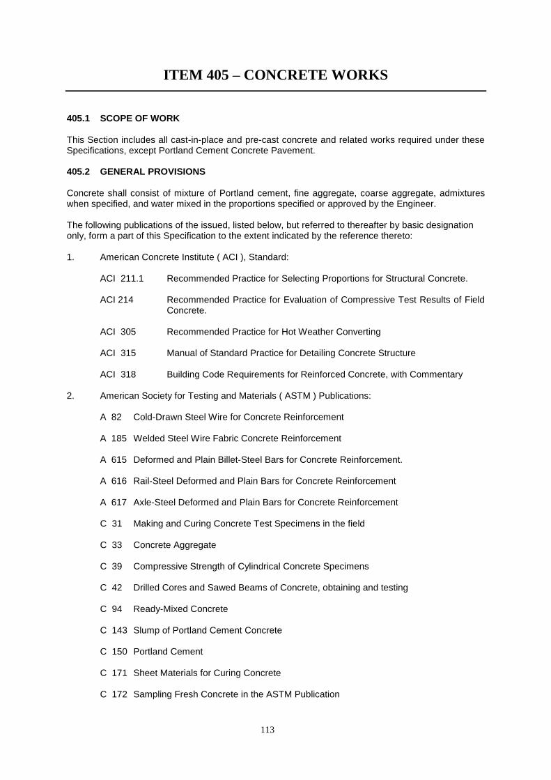
ITEM 405 – CONCRETE WORKS
405.1 SCOPE OF WORK This Section includes all cast-in-place and pre-cast concrete and related works required under these Specifications, except Portland Cement Concrete Pavement. 405.2 GENERAL PROVISIONS Concrete shall consist of mixture of Portland cement, fine aggregate, coarse aggregate, admixtures when specified, and water mixed in the proportions specified or approved by the Engineer. The following publications of the issued, listed below, but referred to thereafter by basic designation only, form a part of this Specification to the extent indicated by the reference thereto: 1. American Concrete Institute ( ACI ), Standard:
ACI 211.1 Recommended Practice for Selecting Proportions for Structural Concrete.
ACI 214 Recommended Practice for Evaluation of Compressive Test Results of Field
Concrete. ACI 305 Recommended Practice for Hot Weather Converting
ACI 315 Manual of Standard Practice for Detailing Concrete Structure
ACI 318 Building Code Requirements for Reinforced Concrete, with Commentary
2. American Society for Testing and Materials ( ASTM ) Publications:
A 82 Cold-Drawn Steel Wire for Concrete Reinforcement
A 185 Welded Steel Wire Fabric Concrete Reinforcement
A 615 Deformed and Plain Billet-Steel Bars for Concrete Reinforcement.
A 616 Rail-Steel Deformed and Plain Bars for Concrete Reinforcement
A 617 Axle-Steel Deformed and Plain Bars for Concrete Reinforcement
C 31 Making and Curing Concrete Test Specimens in the field
C 33 Concrete Aggregate
C 39 Compressive Strength of Cylindrical Concrete Specimens
C 42 Drilled Cores and Sawed Beams of Concrete, obtaining and testing
C 94 Ready-Mixed Concrete
C 143 Slump of Portland Cement Concrete
C 150 Portland Cement
C 171 Sheet Materials for Curing Concrete
C 172 Sampling Fresh Concrete in the ASTM Publication

114
C 173 Air Content of Freshly Mixed Concrete by the Volumetric Method
C 192 Making and Curing Concrete Test Specimens in the Laboratory C 231 Air Content of Freshly Mixed Concrete by the Pressure Method
C 260 Air-Entraining Admixture for Concrete C 309 Liquid Membrane-Forming Compounds for Curing Concrete
C 494 Chemical Admixture for Concrete
C 1751 Preformed Expansion Joint Fillers for Concrete Paving and Structural Construction.
(Non-extruding and Resilient Bituminous Types ) 3. American Welding Society ( AWS )
D.12.1 Welding Reinforcing Steel, Metal Inserts and Connections in Reinforced Concrete Construction.
4. Philippine Standard (PS) 681 – 04 .02, 1975
DSB 275 Steel Bars for Concrete Reinforcement 405.3 SUBMITTALS Refer to General and Special Requirements of the Contract. Test Reports and Certificates shall be furnished for approval before delivery of certified or testes materials to the Project Site. 405.4 CLASSES OF CONCRETE AND USAGE 405.4.1 STRENGTH REQUIREMENTS: Concrete of the various classes indicated and as required under other sections, and unless specified in the plan shall be proportioned and mixed for the following strength:
Class Size of Aggregate (mm)
Specified Compressive Strength
28 days f’c = kg/sq.cm.
A-A 25 420
A 40 240
B 40 210
C 50 175
Seal 25 240
In addition to the above, the maximum permissible water-cement ratio by weight shall not be greater than 0.55 unless otherwise the Engineer. 405.4.2 USAGE Concrete of the various classes to be used shall be as follows: 1. Class A-A concrete: For pre-stressed concrete structures and members. 2. Class A concrete: For pre-cast structure, superstructures and heavily reinforced substructures
which include slabs beams, walls, girders, columns, arch ribs, box culverts, reinforce abutments, retaining walls, reinforced footings and foundation of buildings.

115
1. Class B concrete: Footings, pedestals, foundation of equipment, retaining wall, curb, slab on grade, pipe bedding gravity walls, unreinforced or with only a small amount of reinforcement.
2. Class C concrete: Leveling concrete. 3. Class Seal: Concrete deposited in water 405.4.3 Additives acceptable to the Engineer shall be used for all reinforced concrete structures exposed to salt water action. 405.5 MATERIALS
405.5.1 CEMENT Except when specifically approved by the Engineer only one brand of cement shall be used for any individual structure. In determining the approved mix, only Portland Cement shall be used. 1. Portland Cement: ASTM C 150, Type I 2. High-Early Strength Portland Cement Type III may be used for pre-cast concrete.
Cement Type III shall conform to ASTM C 150 with a tricalcium aluminate limited to 8 percent.
405.5.2 ADMIXTURES
Shall conform to the following: 1. Air-Entraining Admixtures: ASTM C 260 2. Admixture other than air-entraining agent shall conform to ASTM C 494. 3. Admixture containing chloride ions, or other ions producing deleterious effects,
shall not be used.
405.5.3 AGGREGATES: 1. Coarse Aggregates: Conforming to ASTM C 33 and having nominal sizes passing
38.0 mm to 19.00 mm, 19.0 mm to 9.5 mm to No. 4 sieve. The material shall be well graded between the limits indicated and individually stocked piled. It shall be the Contractor’s responsibility to blend the materials to meet the gradation requirements for various type of concrete as specified herein.
a. Nominal sizes for combined gradation shall be as follows:
Table 405.1 - Grading Requirements for Coarse Aggregate
Sieve Designation Mass Percent Passing for
Standard Alternate Class Class Class Class Class
Mm US Standard
B C A A-A Seal
63 2 ½ “ 100
50 2 “ 95-100 100
37.50 1 ½ “ 95-100 100
25 1 “ 35-70 90-100 100
19.0 ¾” 35-70 90-100 100

116
The measured cement content shall be within plus ( + ) or minus ( - ) 2 mass percent of the design cement content.
2. Fine aggregate: ASTM 33 except for gradation which has been revised to meet local
conditions. Unless otherwise required by the Engineer, grading of fine aggregate shall be as follows:
ASTM Sieve By Weight Passing
9.5 mm ( 3/8”) 100
No. 4 90-100
No. 8 80-100
No. 16 50-90
No. 30 25-60
No. 50 10-30
No. 100 2-10
a. Grading of fine aggregate shall be reasonably uniform and fineness modulus
thereof shall not vary more than 0.2 from that of the representative sample on which mix proportions of concrete are based.
b. Due care shall be taken to prevent segregation.
405.5.4 WATER The water used in concrete, mortar and grout shall be free from objectionable quantities of silt, organic matter, alkali, salts and other impurities.
405.5.5 ANCHORAGE ITEMS:
a. Dowels for anchoring mechanical items to concrete shall be of manufacturer’s standard and of types required to engage with the anchors to be provided and installed therein under other sections of these Specifications and shall be subject to the approval of the Engineer.
b. Slots shall be dovetail-type, of not lighter than 24-gauge zinc-coated steel,
with filler that prevents concrete or water from entering and that can be easily removed or punctured for installing anchors.
c. Inserts for suspended ceilings: Wire inserts for attachment of wire hangers for
suspended ceilings shall not be lighter than 7-gauge zinc-coated steel wire. When flat iron or steel hangers are to be used zinc-coated inserts of the same section shall be set in the concrete.
d. Inserts for bolt hangers shall be of malleable iron or of cast of wrought steel.
Inserts for bolt hangers shall either be threaded or slotted as required by the types of hanger to be used. Threaded inserts shall have integral lugs to prevent turning.
12.5 ½ “ 10-30 25-60 90-100
9.5 3/8 “ 10-30 20-55 40-70
4.75 No. 4 0.5 0.5 0.10 0.10 0.15
117
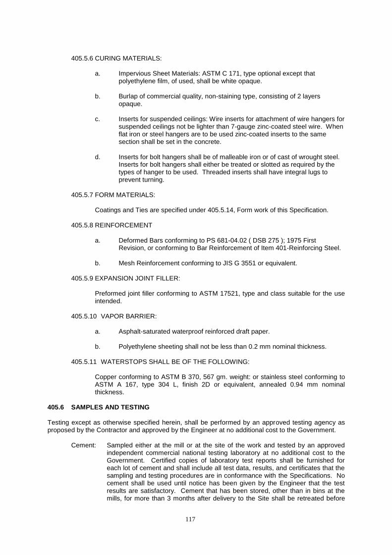
405.5.6 CURING MATERIALS:
a. Impervious Sheet Materials: ASTM C 171, type optional except that
polyethylene film, of used, shall be white opaque.
b. Burlap of commercial quality, non-staining type, consisting of 2 layers opaque.
c. Inserts for suspended ceilings: Wire inserts for attachment of wire hangers for
suspended ceilings not be lighter than 7-gauge zinc-coated steel wire. When flat iron or steel hangers are to be used zinc-coated inserts to the same section shall be set in the concrete.
d. Inserts for bolt hangers shall be of malleable iron or of cast of wrought steel.
Inserts for bolt hangers shall either be treated or slotted as required by the types of hanger to be used. Threaded inserts shall have integral lugs to prevent turning.
405.5.7 FORM MATERIALS:
Coatings and Ties are specified under 405.5.14, Form work of this Specification.
405.5.8 REINFORCEMENT
a. Deformed Bars conforming to PS 681-04.02 ( DSB 275 ); 1975 First
Revision, or conforming to Bar Reinforcement of Item 401-Reinforcing Steel.
b. Mesh Reinforcement conforming to JIS G 3551 or equivalent.
405.5.9 EXPANSION JOINT FILLER:
Preformed joint filler conforming to ASTM 17521, type and class suitable for the use intended.
405.5.10 VAPOR BARRIER:
a. Asphalt-saturated waterproof reinforced draft paper.
b. Polyethylene sheeting shall not be less than 0.2 mm nominal thickness.
405.5.11 WATERSTOPS SHALL BE OF THE FOLLOWING:
Copper conforming to ASTM B 370, 567 gm. weight: or stainless steel conforming to ASTM A 167, type 304 L, finish 2D or equivalent, annealed 0.94 mm nominal thickness.
405.6 SAMPLES AND TESTING Testing except as otherwise specified herein, shall be performed by an approved testing agency as proposed by the Contractor and approved by the Engineer at no additional cost to the Government.
Cement: Sampled either at the mill or at the site of the work and tested by an approved independent commercial national testing laboratory at no additional cost to the Government. Certified copies of laboratory test reports shall be furnished for each lot of cement and shall include all test data, results, and certificates that the sampling and testing procedures are in conformance with the Specifications. No cement shall be used until notice has been given by the Engineer that the test results are satisfactory. Cement that has been stored, other than in bins at the mills, for more than 3 months after delivery to the Site shall be retreated before
118
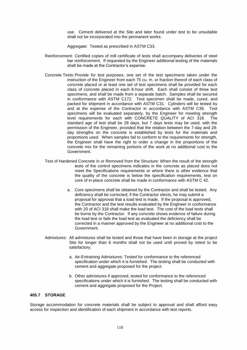
use. Cement delivered at the Site and later found under test to be unsuitable shall not be incorporated into the permanent works.
Aggregate: Tested as prescribed in ASTM C33. Reinforcement: Certified copies of mill certificate of tests shall accompany deliveries of steel
bar reinforcement. If requested by the Engineer additional testing of the materials shall be made at the Contractor’s expense.
Concrete Tests: Provide for test purposes, one set of the test specimens taken under the
instruction of the Engineer from each 75 cu. m. or fraction thereof of each class of concrete placed or at least one set of test specimens shall be provided for each class of concrete placed in each 8-hour shift. Each shall consist of three test specimens, and shall be made from a separate batch. Samples shall be secured in conformance with ASTM C172. Test specimen shall be made, cured, and packed for shipment in accordance with ASTM C31. Cylinders will be tested by and at the expense of the Contractor in accordance with ASTM C39. Test specimens will be evaluated separately, by the Engineer for meeting strength level requirements for each with CONCRETE QUALITY of ACI 318. The standard age of test shall be 28 days, but 7 days tests may be used, with the permission of the Engineer, provided that the relation between the 7-day and 28-day strengths on the concrete is established by tests for the materials and proportions used. When samples fail to conform to the requirements for strength, the Engineer shall have the right to order a change in the proportions of the concrete mix for the remaining portions of the work at no additional cost to the Government.
Test of Hardened Concrete in or Removed from the Structure: When the result of the strength
tests of the control specimens indicates in the concrete as placed does not meet the Specifications requirements or where there is other evidence that the quality of the concrete is below the specification requirements, test on core of in-place concrete shall be made in conformance with ASTM C 42.
a. Core specimens shall be obtained by the Contractor and shall be tested. Any
deficiency shall be corrected; if the Contractor elects, he may submit a proposal for approval that a load test is made. If the proposal is approved, the Contractor and the test results evaluated by the Engineer in conformance with 20 of ACI 318 shall make the load test. The cost of the load tests shall be borne by the Contractor. If any concrete shows evidence of failure during the load test or fails the load test as evaluated the deficiency shall be corrected in a manner approved by the Engineer at no additional cost to the Government.
Admixtures: All admixtures shall be tested and those that have been in storage at the project
Site for longer than 6 months shall not be used until proved by retest to be satisfactory.
a. Air-Entraining Admixtures: Tested for conformance to the referenced
specification under which it is furnished. The testing shall be conducted with cement and aggregate proposed for the project.
b. Other admixtures if approved, tested for conformance to the referenced
specifications under which it is furnished. The testing shall be conducted with cement and aggregate proposed for the Project.
405.7 STORAGE Storage accommodation for concrete materials shall be subject to approval and shall afford easy access for inspection and identification of each shipment in accordance with test reports.
119
Cement: Immediate upon receipt at the Site, the Cement shall be stored separately in a dry weather tight, properly ventilated structure, with of adequate provisions for prevention or absorption of moisture. Cement bags should not be stacked more than 13 bags high. The cement most likely to have been exposed to moisture or stored in bags for more than 3 months shall not be used unless proven by test to be in good condition.
Aggregate: Stored to assure good drainage, to preclude inclusion of foreign matter, and to
preserve the gradation. 405.8 FORMWORK Forms: Designed, constructed, and maintained so as to insure that, after removal, the
finished concrete members will have true surfaces, free of offset, waving or bulges, and will conform accurately to the indicated shapes, dimensions, .lines, elevation, and positions in the plan. Form surfaces that will be contact with concrete shall be thoroughly cleaned before each use.
405.8.1 DESIGN
Studs and wale shall be spaced to prevent deflection of form materials. Forms and joints shall be sufficiently tight to prevent leakage of grout and cement paste during placing of concrete. Juncture of formwork panels shall occur at vertical control joints, and construction joints. Forms placed on successive units for continuous surfaces shall be fitted in accurate alignment to assure smooth completed surface free from irregularities and signs of discontinuity. Temporary opening shall be arranged to wall and where otherwise required to facilitate cleaning and inspection. Forms shall be readily removable without impact, shock, or damage to the concrete.
405.8.2 CONCRETE SURFACES TO BE EXPOSED Form surfaces that will be in contact with concrete shall be of materials that is non-reactive with concrete and that will produce concrete surfaces equivalent in smoothness and appearance to that produced by new 1.2 x 2.4 meters plywood panels approved by the Engineer. Smaller size panels shall be used only where required by opening on the above architectural lines or joints, with each area less than 1.2 meters wide formed with single panel accurately cut to the required dimensions. Cut surfaces shall be smooth and treated with form coating. Panel joints that will being contact with concrete shall be smooth and free of offset. Form materials with defects that will impair the texture and appearance of finish surfaces shall not be used. Form lining, if used, shall be installed over solid backing. Column forms shall be made with a minimum number of joints.
405.8.3 CONCRETE SURFACES TO BE UNEXPOSED Form surfaces that will be in contact with concrete shall be sound, tight lumber or other material producing equivalent finish.
405.8.4 SAMPLE CONCRETE PANELS Before constructing structural formwork, sample concrete panel for exposed or painted concrete shall be constructed and approved for smooth finish specified in paragraph FINISHES OF CONCRETE OTHER THAN FLOOR SLABS. The panel shall not be less than 1.8 meter long by 1.2 meter high. Concrete shall be of the approved design mix. Forms shall include a typical joint between form panels. Sample panels shall show tie-hole patching and smooth finish. Sample panels shall be constructed at approved locations, not as part of the structure, and shall be protected from construction operations, weather, and other damage until acceptance of the completed concrete work. The approved sample panel shall be representative of the smooth concrete finish required in the work.