itnc 530 - aps: wyłączny i autoryzowany …€¦ · 2 the itnc 530 from heidenhain has proven...
TRANSCRIPT

February 2010
iTNC 530New Functions withNC Software 340 49x-06
2
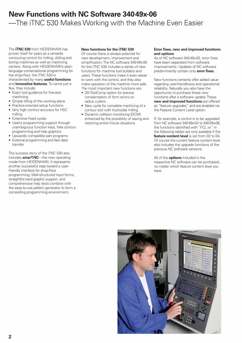
The iTNC 530 from HEIDENHAIN has proven itself for years as a versatile contouring control for milling, drilling and boring machines as well as machining centers. Along with HEIDENHAIN’s plain-language conversational programming for the shop-fl oor, the iTNC 530 is characterized by many useful functions and innovative features. To name just a few, they include:
Exact tool guidance for fi ve-axis • machiningSimple tilting of the working plane• Practice-oriented setup functions• Very high contour accuracy for HSC • millingExtensive fi xed cycles• Useful programming support through • unambiguous function keys, free contour programming and help graphicsUpwardly compatible part programs• External programming and fast data • transfer
The success story of the iTNC 530 also includes smarT.NC—the new operating mode from HEIDENHAIN. It represents another successful step toward a user-friendly interface for shop-fl oor programming. Well-structured input forms, straightforward graphic support, and comprehensive help texts combine with the easy-to-use pattern generator to form a compelling programming environment.
New Functions with NC Software 340 49x-06
—The iTNC 530 Makes Working with the Machine Even Easier
New functions for the iTNC 530
Of course there is always potential for new development, improvement and simplifi cation. The NC software 340 49x-06 for the iTNC 530 includes a series of new functions for machine tool builders and users. These functions make it even easier to work with the control, and they also make operation of the machine more safe. The most important new functions are:
3D-ToolComp option for precise • compensation of form errors on radius cuttersNew cycle for complete machining of a • contour slot with trochoidal millingDynamic collision monitoring (DCM) • enhanced by the possibility of saving and restoring entire fi xture situations
Error fi xes, new and improved functions
and options
As of NC software 340 49x-02, error fi xes have been separated from software improvements. Updates of NC software predominantly contain only error fi xes.
New functions certainly offer added value regarding user-friendliness and operational reliability. Naturally you also have the opportunity to purchase these new functions after a software update: These new and improved functions are offered as “feature upgrades,” and are enabled via the Feature Content Level option.
If, for example, a control is to be upgraded from NC software 340 49x-02 to 340 49x-06, the functions identifi ed with “FCL xx” in the following tables are only available if the feature content level is set from 02 to 04. Of course the current feature content level also includes the upgrade functions of the previous NC software versions.
All of the options included in the respective NC software can be purchased, no matter which feature content level you have.

3
Safe Machining
— Option for Integrated Dynamic Collision Monitoring (DCM): Improvements
The fi fth generation of the DCM software option for dynamic collision monitoring is available now. Since being introduced in 2005, this function has increasingly established itself as an important instrument in reducing costly machine downtimes and relieving the machine operator, especially when manually traversing the machine axes. During manual operation, the TNC automatically reduces the speed if two collision objects come too close to each other, and issues an error message if a collision is imminent. The TNC not only monitors the permanent machine components defi ned by the machine tool builder, but now also monitors fi xtures, tools and tool carriers.
Saving/restoring fi xture situations
The new software makes it possible to save entire fi xture situations and then restore them at a later date. This possibility is a great advantage for integrated fi xture systems, since the measurement process otherwise necessary when the fi xture system is placed on the machine again can be omitted entirely.
Tool carrier management
Now there is also a tool-holder wizard for tool carriers, such as angle heads; its dialog guidance easily leads you through the parameterization of templates. There are also corresponding fi les for HEIDENHAIN touch probes. You simply need to assign them to the touch probe in the tool table. This protects the housings of the various touch probes from collision with fi xtures and permanent machine components.
Improved labeling
The sequence of the touch points is signifi cant when ascertaining the position and orientation of a fi xture. The TNC now provides you as the operator with even better support by clearly labeling the individual touch probes in regard to their position and sequence.

4
Accuracy requirements are becoming increasingly stringent, particularly in the area of 5-axis machining. Complex parts are required to be manufactured with precision and reproducible accuracy even over long periods. KinematicsOpt is an important component that helps you to really fulfi ll these complex requirements: A touch probe cycle measures the rotary axes on your machine fully automatically, regardless of whether they are in the form of tables or spindle heads. A calibration sphere (such as the KKH from HEIDENHAIN) is fi xed at any position on the machine table, and measured with a resolution that you defi ne. In the cycle defi nition you specify the area to be measured for each rotary axis individually.
With this version of the software you can also measure the misalignment of a rotary axis (spindle head or table). For head axes the rotary axis must be measured twice, each time with a stylus of a different length. After exchanging the stylus between the two measurements, the touch probe must be recalibrated. The new calibration cycle 460 automatically calibrates the touch probe using the KKH calibration sphere from HEIDENHAIN already in place.
Support for the measurement of Hirth-coupled spindle heads has also been improved. Positioning of the spindle head can now be performed via an NC macro that the machine tool builder integrates in the calibration cycle.
Possible backlash in a rotary axis can now be ascertained more precisely. By entering an angular value in the new Q432 parameter of Cycle 451, the TNC moves the rotary axis at each measurement point in a manner that its backlash can be ascertained.
Precise Machining
— Calibrating Rotary Axes with KinematicsOpt (Option):Improvements
�
�
���������
��������
5
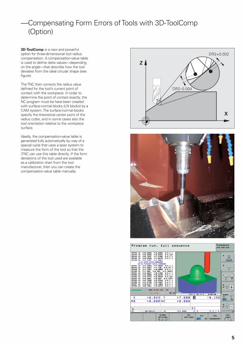
— Compensating Form Errors of Tools with 3D-ToolComp(Option)
3D-ToolComp is a new and powerful option for three-dimensional tool radius compensation. A compensation-value table is used to defi ne delta values—depending on the angle—that describe how the tool deviates from the ideal circular shape (see fi gure).
The TNC then corrects the radius value defi ned for the tool’s current point of contact with the workpiece. In order to determine the point of contact exactly, the NC program must be have been created with surface-normal blocks (LN blocks) by a CAM system. The surface-normal blocks specify the theoretical center point of the radius cutter, and in some cases also the tool orientation relative to the workpiece surface.
Ideally, the compensation-value table is generated fully automatically by way of a special cycle that uses a laser system to measure the form of the tool so that the iTNC can use this table directly. If the form deviations of the tool used are available as a calibration chart from the tool manufacturer, then you can create the compensation-value table manually.

6
Fast Machining
—Machining Any Contour Slots with Trochoidal Milling
The new machining cycle 275, TROCHOIDAL SLOT, enables highly effi cient complete machining of any slots. The roughing process consists of trochoidal motions (Greek “trochos” = wheel). The TNC calculates the milling path by superimposing a linear forward motion over a circular motion of the cutter. This procedure is referred to as trochoidal milling. It is used particularly for milling high-strength or hardened materials, where the high loads placed on the tool and machine usually only permit small infeeds. With trochoidal milling, on the other hand, large cutting depths and high cutting speeds are possible, since the prevailing cutting conditions do not increase the wear and tear on the tool. On the contrary, the entire length of the cutting edge of indexable inserts can be used. This increases the chip volume per tooth, and protects the machine. Enormous amounts of time can be saved by combining this milling method with the integrated adaptive feed control (AFC) option.
The slot to be machined is described in a contour subprogram as a contour train. In cycle 275, whose defi nition is nearly identical to slot cycle 253, you defi ne the slot’s dimensions as well as the cutting data. Any residual material remaining can then easily be removed with a subsequent fi nishing cut.

7
Convenient Machining
—The HR 520 Handwheel Increases Operator Comfort
Electronic handwheels facilitate manual traverse of the axes during setup operations. However, the TNC also provides complex functions for superimposed traverse of the axes via handwheel during automatic operation. Such functions are in daily use especially in large-scale mold making, and are a basic prerequisite for effective operation of the machine.
Operator benefi ts of the HR 520
The connection and functions of the HR 520 handwheel are fully compatible to the HR 420 handwheel, so they can be exchanged without any problems.
Furthermore, the HR 520 has a sixth axis direction key, which can be used for the virtual axis, for example. This makes selection and use of the handwheel-
superimposed traverse in virtual axis
direction function much easier.
In addition, the machine tool builder can freely assign machine functions to the six function keys featuring LED indicators. The symbols of the function keys can be exchanged for clear identifi cation of the machine functions. The axis keys can also be adapted exactly to the respective machine confi guration.
8
New Programming Functions
—Miscellaneous
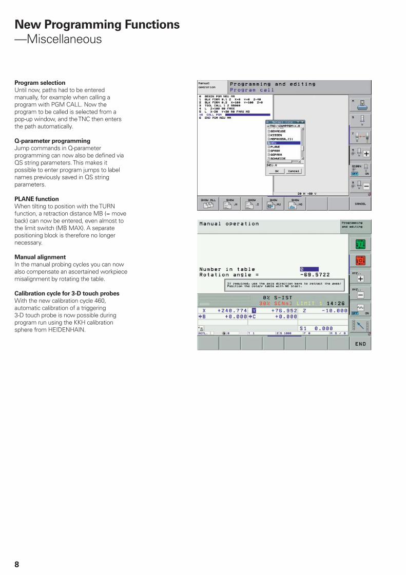
Program selection
Until now, paths had to be entered manually, for example when calling a program with PGM CALL. Now the program to be called is selected from a pop-up window, and the TNC then enters the path automatically.
Q-parameter programming
Jump commands in Q-parameter programming can now also be defi ned via QS string parameters. This makes it possible to enter program jumps to label names previously saved in QS string parameters.
PLANE function
When tilting to position with the TURN function, a retraction distance MB (= move back) can now be entered, even almost to the limit switch (MB MAX). A separate positioning block is therefore no longer necessary.
Manual alignment
In the manual probing cycles you can now also compensate an ascertained workpiece misalignment by rotating the table.
Calibration cycle for 3-D touch probes
With the new calibration cycle 460, automatic calibration of a triggering 3-D touch probe is now possible during program run using the KKH calibration sphere from HEIDENHAIN.
9
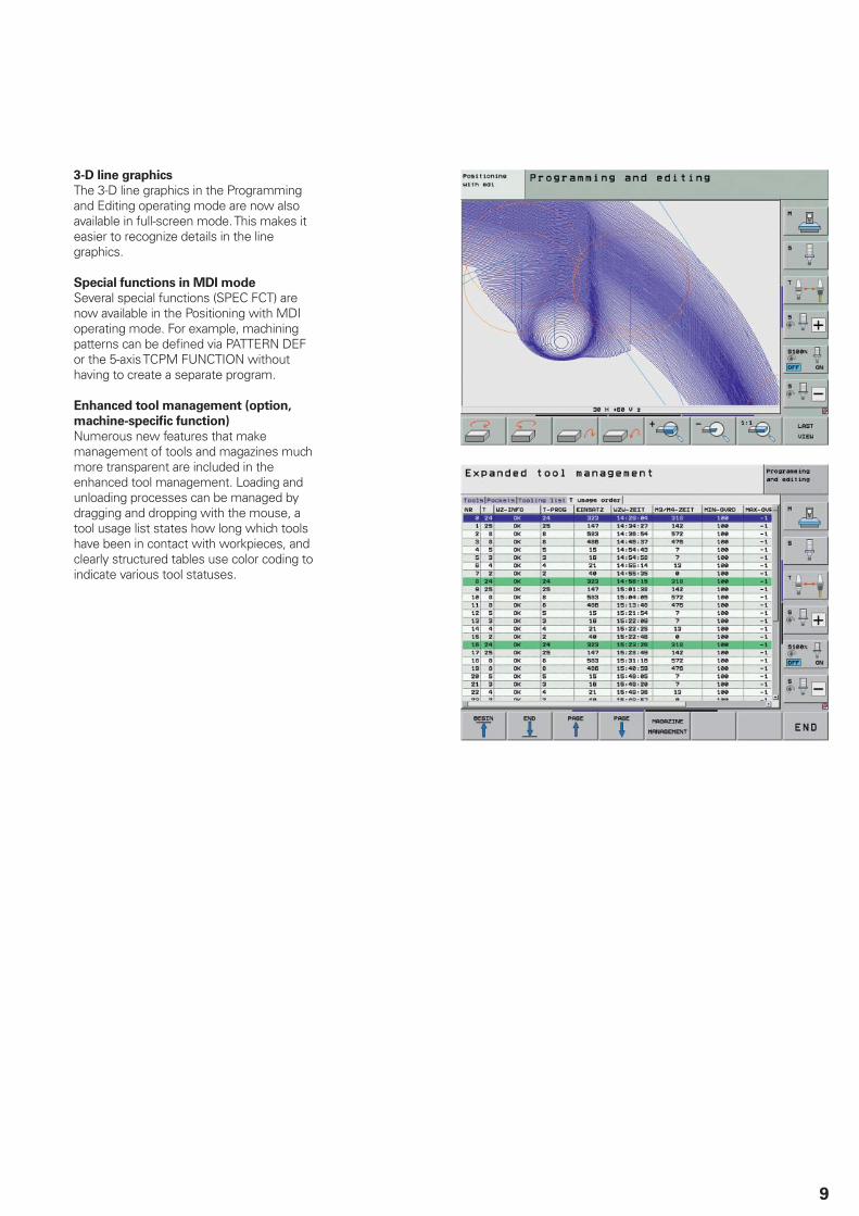
3-D line graphics
The 3-D line graphics in the Programming and Editing operating mode are now also available in full-screen mode. This makes it easier to recognize details in the line graphics.
Special functions in MDI mode
Several special functions (SPEC FCT) are now available in the Positioning with MDI operating mode. For example, machining patterns can be defi ned via PATTERN DEF or the 5-axis TCPM FUNCTION without having to create a separate program.
Enhanced tool management (option,
machine-specifi c function)
Numerous new features that make management of tools and magazines much more transparent are included in the enhanced tool management. Loading and unloading processes can be managed by dragging and dropping with the mouse, a tool usage list states how long which tools have been in contact with workpieces, and clearly structured tables use color coding to indicate various tool statuses.

10
Overview
—All Options in NC Software 340 49x-06
Option
number
Option As of NC
software
340 49x-
ID Comment
0
1
2
3
4
5
6
7
Additional axis 01 354 540-01353 904-01353 905-01367 867-01367 868-01370 291-01370 292-01370 293-01
Additional control loops 1 to 8
8 Software option 1(for MC 420)
01 367 591-01 Machining with a rotary table
Programming of cylindrical contours as if in two axes• Feed rate in mm/min•
Coordinate transformation
Tilting the working plane, PLANE function• Interpolation
Circular in 3 axes with tilted working plane•
9 Software option 2(for MC 420)
01 367 590-01 3-D machining
Particularly jerk-free path control• 3-D tool compensation through surface normal vectors• TCPM: Tool Center Point Management• Keeping the tool normal to the contour• Tool radius compensation normal to the tool direction• Manual traverse in the active tool-axis system•
Interpolation
Linear in 5 axes (subject to export permit)• Spline: execution of splines (3rd degree polynomials)•
Block processing time 0.5 ms
18 HEIDENHAIN DNC 01 526 451-01 Communication with external PC applications over COM component
40 DCM Collision 02 526 452-01 DCM: Dynamic collision monitoring (only with MC 422 B, MC 422 C)
41 Additional language 020303030303040405
530 184-01530 184-02530 184-03530 184-04530 184-06530 184-07530 184-08530 184-09530 184-10
SlovenianSlovakLatvianNorwegianKorean1)
EstonianTurkishRomanianLithuanian
42 DXF Converter 02 526 450-01 Load and convert DXF contours
44 Global PGM Settings 03 576 057-01 Global program settings
45 AFC Adaptive Feed Control 03 579 648-01 Adaptive feed control
46 Python OEM Process 04 579 650-01 Python application on the iTNC2)
48 KinematicsOpt 04 630 916-01 Touch probe cycles for automatic measurement of rotary axes
52 KinematicsComp 05 661 879-01 Three-dimensional compensation2)
53 Feature content level 02 529 969-01 Feature content level
92 3D-ToolComp 06 679 678-01 3-D radius compensation depending on the tool’s contact angle
93 Extended Tool Management 05 676 938-01 Tool management enhanced
1) Only with at least 256 MB RAM 2) Only with at least 512 MB RAM
11
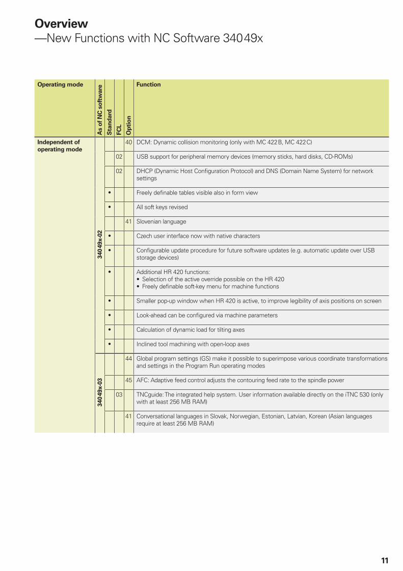
Overview
—New Functions with NC Software 340 49x
Operating mode
As o
f N
C s
oft
ware
Sta
nd
ard
FC
L
Op
tio
n
Function
Independent of
operating mode
340 4
9x-0
2
40 DCM: Dynamic collision monitoring (only with MC 422 B, MC 422 C)
02 USB support for peripheral memory devices (memory sticks, hard disks, CD-ROMs)
02 DHCP (Dynamic Host Confi guration Protocol) and DNS (Domain Name System) for network settings
• Freely defi nable tables visible also in form view
• All soft keys revised
41 Slovenian language
• Czech user interface now with native characters
• Confi gurable update procedure for future software updates (e.g. automatic update over USB storage devices)
• Additional HR 420 functions:Selection of the active override possible on the HR 420• Freely defi nable soft-key menu for machine functions•
• Smaller pop-up window when HR 420 is active, to improve legibility of axis positions on screen
• Look-ahead can be confi gured via machine parameters
• Calculation of dynamic load for tilting axes
• Inclined tool machining with open-loop axes
340 4
9x-0
3
44 Global program settings (GS) make it possible to superimpose various coordinate transformations and settings in the Program Run operating modes
45 AFC: Adaptive feed control adjusts the contouring feed rate to the spindle power
03 TNCguide: The integrated help system. User information available directly on the iTNC 530 (only with at least 256 MB RAM)
41 Conversational languages in Slovak, Norwegian, Estonian, Latvian, Korean (Asian languages require at least 256 MB RAM)

12
Operating modeA
s o
f N
C s
oft
ware
Sta
nd
ard
FC
L
Op
tio
n
Function
Independent of
operating mode
340 4
9x-0
4
• Expanded and completely revised fi le management
• Automatic and manual generation of service fi les for faster error diagnostics
• Tool-change macro for Test Run
04 Graphic display of machine kinematics in the Program Run modes of operation
04 3-D basic rotation light: aligning workpieces in three dimensions
40 Improvements to dynamic collision monitoring (DCM):Handwheel superimposition possible with active DCM in stopped condition• Automatic cancelation of collision protection for touch probe during tool measurement•
41 Turkish and Romanian languages
44 Improvements in global program setting (GS): Traverse with handwheel superimposition in the active tool-axis system (virtual axis) with active TCPM
45 Improvements to adaptive feed control (AFC):Expanded status display• Resetting the reference power in the learning mode• Use of any value as control parameter over PLC•
46 Python OEM process: Simpler integration of OEM applications in the iTNC
48 KinematicsOpt: Touch probe cycles for automatic measurement of rotary axes
340 4
9x-0
5
40 Improvements in dynamic collision monitoring (DCM):Testing the program for possible collisions prior to machining• Fixture monitoring• Simplifi ed tool-carrier management•
41 Lithuanian language
44 Improvements in global program settings (GS)Optimized display of input form• Handwheel superimposition can be used together with M91/M92• Coordinate transformations can be used together with M91/M92•
52 KinematicsComp: Three-dimensional compensation of positioning errors that are due to mechanical causes
• New, additional DG 3D position display: Distance-to-go in the tilted coordinate system
• Separate preset table for pallet presets
• Support of new HR 5xx handwheels
• New tool management based on Python
• TNCguide: help system with improved context sensitivity
• Local QL... Q-parameters and nonvolatile QR... Q-parameters

13
Operating mode
As o
f N
C s
oft
ware
Sta
nd
ard
FC
L
Op
tio
n
Function
Independent of
operating mode
340 4
9x-0
6
92 3D-ToolComp: 3-D radius compensation depending on the tool’s contact angle
• 3-D line graphics in full-screen mode
• Manual operation: Compensate workpiece misalignment through rotation of the table
• SPEC FCT special functions available in MDI mode

14
Operating modeA
s o
f N
C s
oft
ware
Sta
nd
ard
FC
L
Op
tio
n
Function
smarT.NC
340 4
9x-0
2
42 Direct loading of contours from DXF data and saving as smarT.NC contouring programs
02 Cycles for coordinate transformation introduced
02 PLANE function introduced
02 Contour pocket: Separate depth can be assigned for each subcontour
02 Block scan with graphic support
• Entry of cutting speed as alternative to the spindle shaft speed
• Feed rate can also be entered as Fz (feed per tooth) or Fu (feed per revolution)
• Tool data can be edited in a pop-up window during tool selection
• Axis keys now also position the cursor in the forms. The I key (incremental/absolute switchover) and P key (polar/Cartesian switchover) also function for contour programming.
• CUT/COPY/PASTE of one or more units
• Automatic entry of workpiece blank into contour program
• Incremental entry of machining positions in forms for machining units
• Tooltips displayed when using the mouse
340 4
9x-0
3
42 DXF data processing:Separation of laterally joined contour elements• Generate point fi les (.HP fi les) directly from the DXF converter•
03 smarT.NC editor in the Programming and Editing operating mode
• Expanded and completely revised fi le management
• Tool table shown as a fi llable form
03 Machining a contour pocket on a point pattern
03 Individually defi nable positioning heights in point patterns
03 Touch probe units 408 and 409 for setting datums in the centerline of a slot or ridge
03 Setting of probing parameters in the separate unit 441
03 Automatic feed rate reduction in contour pockets during full tool engagement

15
Operating mode
As o
f N
C s
oft
ware
Sta
nd
ard
FC
L
Op
tio
n
Function
smarT.NC
340 4
9x-0
3
• Climb milling/up-cut milling for helical fi nish milling
• Retraction speed for tapping with chip breaking
• Ascertained workpiece misalignment can also be compensated by rotating a C axis
• Zoom function in the pattern generator
• Entry of stopping angle or angular step in a pitch circle defi nition
340 4
9x-0
4
• Unit 141, datum shift
• Unit 256, machining rectangular studs
• Unit 257, machining circular studs
• Unit 799, program end unit
• Unit 22, fi ne roughing: selectable machining strategy
• Unit 209, tapping: defi nable rotational speed of retraction
• Touch probe units 412, 413, 421 and 422: Circles can be measured at either 3 or 4 points
• Inline pattern defi nition with PATTERN DEF
• Taking data from a similar, previously defi ned unit
42 DXF data processing:Handling improvements• Info box displays data on the selected element•
48 Units 450 and 451, KinematicsOpt: touch probe cycles for automatic measurement of rotary axes
340 4
9x-0
5
42 DXF data processing:POLYLINE support• Selection of machining positions with the mouse, including path optimization•
• Unit 241, single-fl uted deep-hole drilling added
48 Improvements in KinematicsOpt:Improved logging in unit 450• Time savings through reduction of the probing paths• Automatic presetting• Hiding individual rotary axes•
• Touch probe units 412, 413, 421 and 422: Type of positioning at clearance height can be selected
• Touch probe units 408 to 419 also write the datum to line 0 of the preset table

16
Operating modeA
s o
f N
C s
oft
ware
Sta
nd
ard
FC
L
Op
tio
n
Function
smarT.NC
340 4
9x-0
6
• Unit 275, trochoidal slot added
• Unit 241, single-fl uted deep-hole drilling: dwell depth added
• Unit 460, calibrate touch probe using calibration sphere added
48 Improvements in KinematicsOpt:Measurement of backlash possible via additional parameter• Improved support of Hirth-coupled spindle heads• Measure and compensate misalignment of a rotary axis•

17
Operating mode
As o
f N
C s
oft
ware
Sta
nd
ard
FC
L
Op
tio
n
Function
Conversational
programming
340 4
9x-0
2
42 Direct loading of contours from DXF data and saving as conversational programs
02 Cycle for global setting of touch-probe parameters
02 Point fi lter for smoothing externally created NC programs
02 3-D line graphics for verifi cation of programs created offl ine
02 Manual traverse in the active tool-axis system
• Entry of cutting speed as alternative to the spindle shaft speed
• Simplifi cation when working with the preset table, incremental correction of preset values possible, correction of the active preset possible
• Contour pockets can now contain signifi cantly more contour elements
• Consideration of an active basic rotation in manual probe cycles
• Measuring log for probing cycles can now also be displayed on the screen during program interruption
• FK transformation selectable as structured plain-language or linearized plain-language
340 4
9x-0
3
42 DXF data processing:Separation of laterally joined contour elements• Generate point fi les (.HP fi les) directly from the DXF converter•
03 Touch probe cycles 408 and 409 for setting datums in the centerline of a slot or ridge
03 Touch-probe cycle 4 for three-dimensional measurements. Toggle between showing the measurement results in the coordinate system of the workpiece or the machine
03 Automatic feed rate reduction in contour pockets during full tool engagement
• Climb milling/up-cut milling for helical fi nish milling
• Retraction speed for tapping with chip breaking
• Ascertained workpiece misalignment can also be compensated by rotating a C axis

18
Operating modeA
s o
f N
C s
oft
ware
Sta
nd
ard
FC
L
Op
tio
n
Function
Conversational
programming
340 4
9x-0
4
• Cycle 256, machining rectangular studs
• Cycle 257, machining circular studs
• Cycle 22, fi ne roughing: selectable machining strategy
• Cycle 209, tapping: defi nable rotational speed of retraction
• Touch probe cycles 412, 413, 421 and 422: circles can be measured at either 3 or 4 points
• Special functions of smarT.NC available for conversational programming:Defi ning machining patterns with PATTERN DEF• Defi ning cycle parameters globally with GLOBAL DEF•
• File management (copying, moving, deleting) from within the NC program
42 DXF data processing:Handling improvements• Info box displays data on the selected element•
48 KinematicsOpt: touch probe cycles for automatic measurement of rotary axes
340 4
9x-0
5
• Cycle 241, single-fl uted deep-hole drilling added
• Touch probe cycles 412, 413, 421 and 422: Type of positioning at clearance height can be selected
42 DXF data processing:POLYLINE support• Selection of machining positions with the mouse, including path optimization•
• Touch probe cycle 484 for calibrating the TT 449 infrared tool touch probe
• Touch probe cycles 408 to 419 also write the datum to line 0 of the preset table
48 Improvements in KinematicsOpt:Improved logging in cycle 450• Time savings through shortening of the probing paths• Automatic presetting• Hiding individual rotary axes•
340 4
94-0
6
• Touch-probe cycle 460, calibration added
• Cycle 275, trochoidal slot added
• Cycle 241, single-fl uted deep-hole drilling: dwell depth added
• Program selection window for PGM calls added
• PLANE function: Retraction value for tilting to position with the TURN function added
• Q-parameter programming: Program jumps can be controlled via QS string parameters
48 Improvements in KinematicsOpt:Measurement of backlash possible via additional parameter• Improved support of Hirth-coupled spindle heads• Measure and compensate misalignment of a rotary axis•

19
Operating mode
As o
f N
C s
oft
ware
Sta
nd
ard
FC
L
Op
tio
n
Function
ISO
340 4
94-0
2
• PLANE function also in possible in ISO
Programming
station
• Virtual keyboard can be displayed with new version of the programming station
• PLC program provided for optional installation (can be used to move axes)
• Access to the PLC with the keyword “PLC”
• All options and FCL functions are enabled
340 4
94-0
4 • Support for Windows Vista
• iTNC programming station available with network license

PH Machinebanks` CorporationQuezon City, Philippines 1113E-mail: [email protected]
PL APS02-489 Warszawa, Polandwww.apserwis.com.pl
PT FARRESA ELECTRÓNICA, LDA.4470 - 177 Maia, Portugalwww.farresa.pt
RO HEIDENHAIN Reprezentanta RomaniaBrasov, 500338, Romaniawww.heidenhain.ro
RS Serbia − BG
RU OOO HEIDENHAIN125315 Moscow, Russiawww.heidenhain.ru
SE HEIDENHAIN Scandinavia AB12739 Skärholmen, Swedenwww.heidenhain.se
SG HEIDENHAIN PACIFIC PTE LTD.Singapore 408593www.heidenhain.com.sg
SK KOPRETINA TN s.r.o.91101 Trencin, Slovakiawww.kopretina.sk
SL Posredništvo HEIDENHAINNAVO d.o.o.2000 Maribor, Sloveniawww.heidenhain-hubl.si
TH HEIDENHAIN (THAILAND) LTDBangkok 10250, Thailandwww.heidenhain.co.th
TR T&M Mühendislik San. ve Tic. LTD. STI·.
34728 Ümraniye-Istanbul, Turkeywww.heidenhain.com.tr
TW HEIDENHAIN Co., Ltd.Taichung 40768, Taiwan R.O.C.www.heidenhain.com.tw
UA Gertner Service GmbH Büro Kiev 01133 Kiev, Ukrainewww.gertner.biz
US HEIDENHAIN CORPORATIONSchaumburg, IL 60173-5337, USAwww.heidenhain.com
VE Maquinaria Diekmann S.A. Caracas, 1040-A, VenezuelaE-mail: [email protected]
VN AMS Advanced Manufacturing Solutions Pte LtdHCM City, Viêt NamE-mail: [email protected]
ZA MAFEMA SALES SERVICES C.C.Midrand 1685, South Africawww.heidenhain.co.za
ES FARRESA ELECTRONICA S.A.08028 Barcelona, Spainwww.farresa.es
FI HEIDENHAIN Scandinavia AB02770 Espoo, Finlandwww.heidenhain.fi
FR HEIDENHAIN FRANCE sarl92310 Sèvres, Francewww.heidenhain.fr
GB HEIDENHAIN (G.B.) LimitedBurgess Hill RH15 9RD, United Kingdomwww.heidenhain.co.uk
GR MB Milionis Vassilis17341 Athens, Greecewww.heidenhain.gr
HK HEIDENHAIN LTDKowloon, Hong KongE-mail: [email protected]
HR Croatia − SL
HU HEIDENHAIN Kereskedelmi Képviselet1239 Budapest, Hungarywww.heidenhain.hu
ID PT Servitama Era ToolsindoJakarta 13930, IndonesiaE-mail: [email protected]
IL NEUMO VARGUS MARKETING LTD.Tel Aviv 61570, IsraelE-mail: [email protected]
IN HEIDENHAIN Optics & ElectronicsIndia Private LimitedChennai – 600 031, Indiawww.heidenhain.in
IT HEIDENHAIN ITALIANA S.r.l.20128 Milano, Italywww.heidenhain.it
JP HEIDENHAIN K.K.Tokyo 194-0215, Japanwww.heidenhain.co.jp
KR HEIDENHAIN Korea LTD.Gasan-Dong, Seoul, Korea 153-782www.heidenhain.co.kr
ME Montenegro − SL
MK Macedonia − BG
MX HEIDENHAIN CORPORATION MEXICO20235 Aguascalientes, Ags., MexicoE-mail: [email protected]
MY ISOSERVE Sdn. Bhd56100 Kuala Lumpur, MalaysiaE-mail: [email protected]
NL HEIDENHAIN NEDERLAND B.V.6716 BM Ede, Netherlandswww.heidenhain.nl
NO HEIDENHAIN Scandinavia AB7300 Orkanger, Norwaywww.heidenhain.no
AR NAKASE SRL.B1653AOX Villa Ballester, Argentinawww.heidenhain.com.ar
AT HEIDENHAIN Techn. Büro Österreich83301 Traunreut, Germanywww.heidenhain.de
AU FCR Motion Technology Pty. LtdLaverton North 3026, AustraliaE-mail: [email protected]
BA Bosnia and Herzegovina − SL
BE HEIDENHAIN NV/SA1760 Roosdaal, Belgiumwww.heidenhain.be
BG ESD Bulgaria Ltd.Sofi a 1172, Bulgariawww.esd.bg
BR DIADUR Indústria e Comércio Ltda.04763-070 – São Paulo – SP, Brazilwww.heidenhain.com.br
BY BelarusGERTNER Service GmbH50354 Huerth, Germanywww.gertner.biz
CA HEIDENHAIN CORPORATIONMississauga, OntarioL5T2N2, Canadawww.heidenhain.com
CH HEIDENHAIN (SCHWEIZ) AG8603 Schwerzenbach, Switzerlandwww.heidenhain.ch
CN DR. JOHANNES HEIDENHAIN (CHINA) Co., Ltd.Beijing 101312, Chinawww.heidenhain.com.cn
CZ HEIDENHAIN s.r.o.102 00 Praha 10, Czech Republicwww.heidenhain.cz
DK TP TEKNIK A/S2670 Greve, Denmarkwww.tp-gruppen.dk
DE HEIDENHAIN Technisches Büro Nord12681 Berlin, Deutschland{ 030 54705-240
HEIDENHAIN Technisches Büro Mitte08468 Heinsdorfergrund, Deutschland{ 03765 69544
HEIDENHAIN Technisches Büro West44379 Dortmund, Deutschland{ 0231 618083-0
HEIDENHAIN Technisches Büro Südwest70771 Leinfelden-Echterdingen, Deutschland{ 0711 993395-0
HEIDENHAIN Technisches Büro Südost83301 Traunreut, Deutschland{ 08669 31-1345
Vollständige und weitere Adressen siehe www.heidenhain.deFor complete and further addresses see www.heidenhain.de
Zu
m A
bh
eft
en
hie
r fa
lzen
! /
Fo
ld h
ere
fo
r fi
lin
g!
������������ ��� ��������������� ��������������������������������������� �������������� ������������������ ��!�"����������
������ !���� ��!�
732 738-21 · 20 · 2/2010 · F&W · Printed in Germany