itp-tvc-eurofighter
DESCRIPTION
itp-tvc-eurofighterTRANSCRIPT

11-1
Industria de Turbo Propulsores, S.A.
Thrust Vectoring Nozzlefor Modern Military Aircraft
Daniel Ikaza
Industria de Turbo Propulsores S.A. (ITP)Parque Tecnológico, edificio 300
48170 Zamudio, [email protected]
presented atNATO R&T ORGANIZATION Symposium
onACTIVE CONTROL TECHNOLOGY FOR ENHANCED PERFORMANCE
OPERATIONAL CAPABILITIES OF MILITARY AIRCRAFT,LAND VEHICLES AND SEA VEHICLES
Braunschweig, Germany8th-11th May 2000
Fig. 1.- CFD Model of a TVN
ABSTRACT
This paper describes the technical features of the ThrustVectoring Nozzle (TVN) developed by ITP and itsadvantages for modern military aircraft. It is presented inconjunction with two other papers by DASA (ThrustVectoring for Advanced Fighter Aircraft High Angle ofAttack Intake Investigations) and MTU-München (IntegratedThrust Vector Jet Engine Control) respectively.
Thrust Vectoring: advantages and technology
Thrust Vectoring is a relatively new technology which hasbeen talked about for some time, and it can provide modernmilitary aircraft with a number of advantages regardingperformance (improved manoeuverability, shorter take-offand landing runs, extended flight envelope, etc...) andsurvivability (control possible in post-stall condition, fasterreaction in combat, etc...).
Additionally, as a byproduct of Thrust Vectoring, there isalso the capacity to independently control the exit area of thenozzle, which allows to have always an “adapted” nozzle toevery flight condition and engine power setting. This meansan improvement in thrust which in cases can be as high as7%.
There are several types of Thrust Vectoring Nozzles. Forexample, there are 2-D (or single-axis; or Pitch-only) ThrustVectoring Nozzles, and there are 3-D (or multi-axis; or Pitchand Yaw) Thrust Vectoring Nozzles. The ITP Nozzle is a full3-D Vectoring Nozzle. Also, there are different ways toachieve the deflection of the gas jet: the most efficient one isby mechanically deflecting the divergent section only, henceminimizing the effect on the engine upstream of the throat(sonic) section.
The major aerodynamic aspects of the design of a ThrustVectoring Nozzle include the correct dimensioning of thevectoring envelope, accounting for the difference between“geometrical” and “effective” vectoring; as well as thesealing pattern of the master and slave petals at and aroundthe throat section.
Paper presented at the RTO AVT Symposium on “Active Control Technology forEnhanced Performance Operational Capabilities of Military Aircraft, Land Vehicles and Sea Vehicles”,
held in Braunschweig, Germany, 8-11 May 2000, and published in RTO MP-051.

11-2
Fig. 2.- TVN ground tests at ITP
ITP Design
The ITP concept consists of a patented design featuring theso-called “Three-Ring-System”, which allows all nozzlefunctions (Throat Area, Exit Area, Pitch Vectoring and YawVectoring) to be performed with a minimum number ofactuators, which, in turn, leads to an optimized mass andoverall engine efficiency.
The nozzle is controlled by four independent hydraulicactuators, each one with its own servovalve and positiontransducer. The level of redundancy will depend on the exactapplication.
There is also, only at design level, a simplified variant of thenozzle, with three actuators only, which has basically thesame functions of the 4-actuator one, except the independentexit area control. This variant would be a little lighter, but itmisses the thrust improvement capability.
The reaction bars of the ITP nozzle present an arrangementwhich allows for high deflection angles, without the risk ofpetal overlapping and/or disengagement. The presentprototype has demonstrated deflections up to 23º, but studieshave been performed of variants of the nozzle with deflectionangles of up to 30-35º.
Finally, the ITP design makes use of a partial “Balance-Beam” effect, which takes advantage of the energy of the gasstream, on one hand to help close the nozzle under highpressures, hence reducing the maximum load required fromthe actuators; on the other hand to allow self-closing of thenozzle in case of hydraulic loss under low pressureconditions, specially interesting to retain thrust for take-off.
ITP TVN programme - Past, Present and Future
ITP has dedicated a research programme on Thrust Vectoringtechnology which started back in 1991, and which met animportant milestone as is the ground testing of a prototypenozzle at the ITP facilities in Ajalvir, near Madrid, in 1998.Altitude testing is scheduled for 2000.
The next major goal will be the realisation of a flightprogramme, in order to validate the system in flight, andevaluate the capabilities and performance of the system as ameans of flight control.
The design used for the ground prototype has been a simpleone, for short life and limited safety. For the flight standard,a number of changes will be introduced, in order to comply
with the very demanding aircraft requirements in terms ofweight, life, safety, etc...
The experience acquired during the ground test phase hashelped ITP learn a lot about the behaviour of the nozzle,showing areas in which the design has to be modified,providing data for the integration of nozzle and enginecontrols, etc... The main outcome of the tests has been theconfirmation that the concept designed is valid and it workssmoothly.
A decisive contribution is being done by ITP’s partnercompany MTU of Munich, Germany, by developing theelectronic Control System.
This programme is making the Thrust Vectoring technologyavailable in Europe for existing military aircraft such asEurofighter, in which the introduction of Thrust Vectoringcould be carried out with a relatively small number ofchanges to the aircraft and to the engine, and could provide itwith an improved performance.
CONTENTS
1.- DEFINITIONS AND ABBREVIATIONS
2.- BACKGROUND
3.- BENEFITS OF THRUST VECTORING AND NOZZLEEXIT AREA CONTROL
4.- TYPES OF THRUST VECTORING
5.- ITP DESIGN: BASELINE AND OPTIONS
6.- ITP THRUST VECTOR PROGRAMME
7.- CONCLUSIONS
8.- ACKNOWLEDGEMENTS
1. - DEFINITIONS AND ABBREVIATIONS
A8 Nozzle throat area
A9 Nozzle exit area
ATF Altitude Test Facility
CFD Computational Fluid Dynamics
Con-Di Convergent-Divergent
DECU Digital Engine Control Unit
DOF Degree of freedom
ESTOL Extremely Short Take-Off and Landing
FCS Flight Control System
R&D Research and Development
RCS Radar Cross Section
SFC Specific Fuel Consumption
SLS Sea Level Static
TVN Thrust Vectoring Nozzle

11-3
2.- BACKGROUND
The Thrust Vectoring Nozzle developed by ITP was initiallydesigned to fit and be compatible with an EJ200 engine,which powers the European Fighter Aircraft EF2000. Thisaircraft is developed by the European consortiumEurofighter, constituted by the companies British Aerospace(UK), DASA (Germany), Alenia (Italy) and CASA (Spain).Similarly, the above engine EJ200 is developed by theEuropean consortium Eurojet, constituted by the companiesRolls-Royce (UK), MTU (Germany), Fiat Avio (Italy) andITP (Spain).
The current EJ200 engine is equipped with a variable-geometry Convergent-Divergent (Con-Di) Nozzle, developedby ITP. This nozzle can modify the area to match the enginerunning point and afterburner setting, but it has no vectoringcapability.
Through a dedicated R&D programme, ITP have nowintroduced a new Thrust Vectoring Nozzle which could beapplied to EJ200 to significantly enhance the capabilities ofEF2000 Aircraft.
Introduction to Military Aircraft Nozzles
In a military aircraft engine with reheat (also calledafterburner or augmentor), the nozzle presents a convergentsection, which has the task to accelerate the gas jet in orderto generate thrust, yet with the characteristic that it must becapable of varying the throat area according to therequirement of the engine running point. These are called“variable geometry convergent” nozzles.
Some nozzles, additionally, comprise a divergent sectiondownstream of the convergent section, which overexpandsthe jet between the throat area and the exit area in order toextract yet some extra thrust. These are called “Variablegeometry convergent-divergent” (or Con-Di) nozzles.
Depending on the level of control upon this divergentsection, variable geometry Con-Di nozzles can be of twotypes:
• One-parameter Nozzles: also called 1-DOF nozzles; theConvergent section (hence Throat Area) is fullycontrolled, and Divergent section (hence Exit Area)follows a pre-defined relationship to the convergentsection behaviour (throat area). The current EJ200 nozzleis of this type.
• Two-parameter Nozzles: also called 2-DOF nozzles; theConvergent section (Throat Area) and Divergent section(Exit area) are fully controlled independently. This typecan match the Divergent section to the exact flightcondition in order to obtain an optimised thrust.
Also there are some intermediate solutions such as “floating”and some other “passive” means of exit area control, whichare outside the scope of this paper.
One solution or the other is chosen according to theparticular requirements of each case, in terms of weight, cost,reliability, thrust, priority missions, etc…
In the case of Thrust Vectoring Nozzles, they also have thetask to direct the jet to generate side thrust to transmit it tothe aircraft structure, so that the aircraft can make use of it asa means of flight and manoeuvre control.
3.- BENEFITS OF THRUST VECTORINGAND NOZZLE EXIT AREA CONTROL
Although the description of benefits of Thrust Vectoring andnozzle exit area control for modern military aircraft is in factthe subject of a separate paper by DASA, a brief descriptionof some of them is given here for reference.
They can be basically grouped in four categories:
• Enhanced performance in conventional flight
• Post-Stall flight
• Increased Safety
• Reduction of aero controls
Enhanced performance in conventional flight
The concept of Thrust Vectoring is often associated withspectacular loop-type manoeuvres performed by smallaircraft in airshow demonstrations or combat simulations,and the operational use of these capabilities is often regardedwith a lot of skepticism, due to the trends of modern aircombat. However, there is a lot more to Thrust Vectoringthan these funny manoeuvres, and in fact the greatestargument in favour of Thrust Vectoring is not found incombat characteristics but rather in conventionalperformance, as described in more detail below:
Stationary Flight Trimming
The use of the Nozzles as a complementary control surfaceallows the aircraft to better optimize its angle of attack instationary level flight for a given flight point and loadconfiguration, hence reducing the drag, which in turn leadsto strong benefits in SFC, and therefore range.
Fig. 3.- Increased Sustained Turn Rate with TVNs
Stationary and Transient Manoeuvres
Similarly to the above case, the nozzles can be used toincrease the maximum load factor that is achievable undercertain circumstances while maintaining the aircraft trimmed.This applies both for stationary manoeuvres (sustained turnrate) and for transient manoeuvres (rapid deceleration).
Nozzle Exit Area Control
As described in the Introduction to military aircraft nozzles,in one-parameter Con-Di nozzles the divergent section(hence A9) follows a pre-defined relationship to the
INCREASED SUSTAINED TURN RATE
Lift
Weight
Drag
Available
Thrust
Conventional Trimming : CASE STUDY:
30,000 ft Mach 1.8
Flaps 6º upMax. Lift: Ref.
Max. Load Factor: Ref.Max. Turn Rate: Ref.
Flaps 2º upNozzles 4º up
Lift Coef.: Ref +14% Load Factor: Ref +9%Turn Rate: Ref +9%
Velocity Vector
Lift
Weight
Drag
Thrust Vectoring Trimming:
Velocity Vector
Rear FlapsTrimming
Thrust VectoringTrimming
AvailableThrust

11-4
convergent section (hence A8). This relationship is optimisedfor an average of all missions, which normally means lowA9/A8 Ratio for dry operations (without reheat) and highA9/A8 Ratio for operations with reheat.
In rough terms, this is reasonably optimised for low speeddry operations (cruise, climb, etc...) and for high speed reheatoperations (high speed strike, etc...), but is not optimised forlow speed reheat operations (take-off) and high speed dryoperations (supersonic cruise).
EXIT AREA OPTIMIZATION
Throat Area
OptimumA9/A8 ratioincludingafterbody
effects
Dry Reheat
Supersonic
Subsonic
FixedSchedule
IndependentA9 control
Supercruise:
7%Thrust increase
Take-off:
2%Thrust increase
Fig. 4.- Optimization of Nozzle Exit Area
The use of an independently controlled divergent sectionallows A9 to be optimised for any engine running conditionat any flight point, and has an improvement especially inthose conditions where one-parameter A9/A8 Ratio is notoptimized.
For example, for a supersonic cruise case (Mach 1.2, altitude36,000 ft, engine at Max Dry condition) of EJ200 engine onEurofighter, the use of independent A9 control could lead toan improvement of up to 7% in installed net thrust relative tothe current performance. This is due to the combination oftwo effects: increase of nozzle internal thrust; and reductionof nozzle external drag.
In addition to thrust increase, independent A9 control alsopermits reduction in SFC for certain flight points.
Reduction of take-off and landing runs
The rotation of the aircraft for take-off and landing can beaccelerated by using Thrust Vectoring. Also, ThrustVectoring can be used to increase angle of attack, hence lift,while maintaining a trimmed aircraft. The combination of allthese effects gives an important reduction in the take-off andlanding runs for an aircraft such as Eurofighter.
Global mission performance
The combined effect of all the above items across a typicalcombat mission could add up to some 3% Fuel saving byusing Thrust Vectoring.
Post-Stall Flight
The most spectacular benefit of Thrust Vectoring, althoughpossibly not the most important, is the fact that it can exertan active control of an aircraft while the main aerodynamicsurfaces are stalled, hence not suitable for control, and thisopens a whole new domain of flight conditions where flightused to be unthinkable.
Extension of flight envelope
The use of Thrust Vectoring permits the aircraft to holdstationary flight in an area of the envelope whereconventional controls are not sufficient.
In the Altitude/Mach-number envelope, Thrust Vectoringpermits an extension of the envelope in the low speed-medium height region. In the Altitude/Mach-number/Angle-of-attack envelope, Thrust Vectoring permits operation atmuch higher values of Angle of attack.
Air superiority
A better control of the aircraft is achieved with ThrustVectoring, especially at low speed conditions, whereconventional aerodynamic controls are not effective, andwhere a good number of combat scenarios are to take place.
ESTOL
The ESTOL concept (Extremely Short Take-Off andLanding) is becoming more and more appealing to militaryaircraft operators, and it consists of performing the Take-offand Landing manoeuvres with the aircraft stalled. It reducestake-off and landing runs by a large amount.
This is only possible with Thrust Vectoring Nozzles, thatoperate when the aerodynamic controls are no longer useful.
Increased safety
This is probably one of the strongest arguments in favour ofThrust Vectoring. The existence of redundant means ofaircraft control allows for a better survivability.
Fig. 5.- Redundant Flight Controls with TVNs
In peace time, an aircraft crash by loss of aerodynamiccontrol could be avoided by the use of Thrust Vectoring.
In war time, damage to aerodynamic control surfaces can becompensated with Thrust Vectoring.
Next Step: reduction of aero controls
Once the Thrust Vectoring system has been sufficientlyvalidated, it will be a primary control for the aircraft. This
Foreplane
Rudder
FlapsLeading EdgeSlats
Nozzles

Center of Gravity (cg)
For trimmed flight, no rotation about cg.
W· Wing Lift
dw• distance
Trimmed Aircraft
w T· Tail Lift
d t· distance
T
Equation: (W x~) + (T x d tl = 0
(Lift of Wing x distance from cg) + (Lift of Tail x distance from cd) - 0

11-5
means that it will allow a gradual reduction of existingconventional aerodynamic control surfaces such ashorizontal and vertical stabilizers. This will have an impact,and there will be a reduction in:
• Mass
• Drag
• Radar Cross Section (RCS)
The extent of these impact could only be properly assessed inthe future, and it will probably not be fully exploited until thenext generation of combat aircraft, but mass reductions of15%-20% of the total aircraft are conceivable.
4.- TYPES OF VECTORING NOZZLES
From the point of view of the type of actuation means, TVNscan be classified:
• Fluidic Actuation: The deflection of the gas flow isachieved by injection of secondary airflows. This type isspecially suitable for fixed-area high expansion nozzles,such as those used in rockets and missiles.
• Mechanical Actuation: The deflection of the gas flow isachieved by mechanical movement of the nozzle, whichis powered by hydraulic or pneumatic actuators. Thistype is specially suitable for variable geometry militaryaircraft nozzles.
* * *
From the point of view of the direction of vectoring, TVNscan be classified:
• Single-Axis TVNs: (also called 2-D or Pitch-only) Thedeflection of the gas flow is achieved in vertical directiononly. They replace and/or complement horizontal controlsurfaces. This type is suitable for all types of variablegeometry military aircraft nozzles.
• Multi-Axis TVNs: (also called 3-D or Pitch and Yaw)The deflection of the gas flow is achieved in anydirection. They replace and/or complement horizontaland vertical control surfaces. This type is speciallysuitable for round nozzles.
* * *
If we focus on 3-D, Con-Di military aircraft TVNs withmechanical actuation, there are several ways to materialisethe vectoring:
• Deflect whole nozzle. The disadvantages are: a largemass has to be moved; and there is a big impact onperformance upstream of the nozzle.
• External Flaps. The disadvantages are: there is a need foradditional mass; and the efficiency of vectoring is verylow.
• Deflect Divergent section. This is the preferred solution.the size of the nozzle is optimised and the effect onperformance is negligible. The ITP Nozzle is of this thirdtype.
EXISTING 3-D THRUST VECTORING SYSTEMSMechanical Actuation, Con-Di Military Nozzles
DEFLECT WHOLE NOZZLE EXTERNAL FLAPS DIVERGENT SECTION
Fig. 6.- Existing types of 3-D TVNs
Regarding the nozzles of the third type, that is, those thatdeflect the flow by orienting the divergent section only, theygenerally need actuation means for:
• Controlling convergent section (hence A8)
• Controlling divergent section (hence vectoring and A9)
Where other designs make use of two separate actuationsystems, the ITP design has a unified actuation system with aminimum total number of actuators.
5.- ITP DESIGN: BASELINE AND OPTIONS
One of the biggest problems encountered when designing aThrust Vectoring Nozzle is how to find a mechanicalconfiguration comprising casing, rings, etc…, which must becompatible with both functions of the nozzle: on one hand,open and close the convergent section to control throat area(optionally open and close the divergent section to controlexit area); and on the other hand to direct the nozzle indirections different to axial, to obtain the jet deflection thatprovides vectored thrust.
The other big problem of a Thrust Vectoring Nozzle is howto find an actuation system (hydraulic, pneumatic, electro-mechanical, mixed, etc..) capable of generating themovements required in the nozzle, to accomplish all theabove functions, and reasonably limited under criteria suchas weight, size, etc…
Many different configurations have been studied at ITP forTVNs, the result being a “baseline” configuration, plus aseries of options available for every particular application.
The main option is the A9 modulation capability, aimed atoptimising the thrust as described above in the chapter“Benefits of Thrust Vectoring and nozzle area control”.
Baseline
The baseline ITP TVN design is a Convergent-divergentaxisymmetric (round) nozzle with multi-axis ThrustVectoring, mechanically actuated, and where the deflectionof the gas flow is achieved by orienting the divergent sectiononly. This way the moving mass is minimized, and thedistortion to the engine turbomachinery upstream of thenozzle is negligible.
It has three degrees of freedom (DOFs), namely: Throat area(A8), Pitch vectoring and Yaw vectoring. Any obliquevectoring is made of a combination of pitch and yaw. Exitarea (A9) follows a certain relationship to A8.
The actuation system consists of only three independenthydraulic actuators, a fact which is made possible by thebasic feature of the design: the “Three-Ring-System”.

11-6
X
OUTERRING
ACTUATORS
Fig. 7.- Three Ring System (3 actuators)
This system consists of three concentric rings which arelinked by pins and form a universal (or “cardan”) joint. Theinner ring is linked to the convergent section of the nozzle,the outer ring is linked to the divergent section through thereaction bars, and the intermediate ring acts as the crossbarbetween the inner and outer rings. The actuators are linked tothe outer ring only. The design of the rings and reaction barsis such that a small tilt angle on the ring is amplified to alarge deflection angle on the divergent section.
The outer ring can be tilted in any direction while the innerring can only keep a normal orientation to the enginecentreline, but they both are forced to keep the same axialposition along the engine. This is the key factor that permitsa full control of the nozzle by acting on the outer ring only,hence minimizing the total number of actuators.
For pure throat area movements, all three actuators move inparallel, hence all three rings follow axially, and A8 is set tothe appropriate value. A9 follows a pre-defined relationshipto A8 according to the dimensions of the mechanism.
For Pitch and/or Yaw vectoring movements, the threeactuators move differently, hence defining a tilt plane of theouter ring. The divergent section will deflect in the directionof that plane. Throat area (A8) is not affected unless thismovement is combined with a throat area movement.
Fig. 8.- Ring Movement in vectoring
Fig. 9.- Nozzle Movement in vectoring
A9 Control option: optimised thrust
This option consists basically of the baseline design, exceptfor the fact that the outer ring is split in two halves, forming a“hinged” outer ring.
It has four degrees of freedom (DOFs), namely Throat Area(A8), Exit Area (A9), Pitch vectoring and Yaw vectoring.Again, any oblique vectoring is achieved by combination ofpitch and yaw.
The actuation system consists of four independent actuators,also linked to the outer ring only.
THREE RING SYSTEM Z
YX
PITCH, A9
YAW, A8
SPLITRING
ACTUATORS
Fig. 10.- Three Ring System (4 actuators)
The same Three Ring principle is used as in the threeactuator version, and A8 and vectoring movements areoperated in a similar way, yet this time with four instead ofthree actuators.
Additionally, pure A9 control movements are performed bymoving top and bottom actuators in parallel while the othertwo stay static, hence “hinging” the outer ring open or close.The divergent section opens or closes relative to the nominalposition, acquiring an “oval” shape. Hence this movement issometimes referred to as “ovalization”. Of course, A9movements can be combined with A8 movements and/orvectoring movements.

11-7
Fig. 11.- Ring Movement in A9 control
Fig. 12.- Nozzle Movement in A9 control
With this configuration there could be an improvement ininstalled net thrust of up to 7% in certain conditions.
In fact, this A9 option could well be considered as thebaseline, leaving the non-A9 configuration as a “simplifiedoption”.
Third Member of the Family: "Two-Ring" Pitch-only Nozzle
This is a simplified version of the ITP Nozzle where theintermediate Ring is deleted, hence reducing some weightand complexity. Outer Ring is split in two as in previousversion.
It retains the four actuators and it has three DOFs (A8, A9,Pitch Vectoring).
It is suitable for application in aircraft with no Post-Stallcapability, but where the benefits in conventional flight areimportant.
SIMPLIFIED TWO-RING SYSTEM FOR PITCH-ONLYAPPLICATIONS
YX
PITCH, A9
A8
SPLITRING
Fig. 13.- "Two-Ring" Pitch-only Nozzle
Other features: "hinged" Reaction Bars
The design of the reaction bars presents “hinged struts”which allow an optimised smooth movement of petals.Where other designs are limited to about 20º geometricdeflection by the disengagement and/or interference betweenpetals, the ITP design allows for growth if required, andstudies have been carried out for deflections up to 30º-35º.
SIMPLE REACTION STRUTS
VECTORING
Disengagement
Interference
Fig. 14a.- Vectoring with simple reaction bars
HINGED REACTION STRUTS
VECTORING OptimizedMovement
Fig. 14b.- Vectoring with hinged reaction bars
Balance-Beam
The ITP TVN makes use of a partial balance-beam effect,which consists of taking advantage of the energy of the gasstream to help close the nozzle in high pressure conditions.
The closing movement of the nozzle is accompanied by anaxial displacement of the throat, so that the volume sweptagainst the gas pressure is modified, in particular morevolume is swept in the low pressure region of the nozzle, andless volume in the high pressure region.

11-8
15% LOWERACTUATOR LOADS
NOZZLE SELF-CLOSINGIF HYDRAULIC LOSSDURING TAKE-OFF
BALANCE BEAM
Fig. 15.- Balance Beam effect
This has two benefitial effects:
• On one hand, in high pressure conditions, the total workperformed by the actuation system upon the gas streamis reduced by as much as 15%, which results in smalleractuator dimensions and better engine efficiency.
• On the other hand, in case of hydraulic loss in lowpressure conditions, the nozzle self-closes, which isparticularly interesting to retain thrust during take-off.
Actuation and Control System
The control system of the nozzle consists of three (baselinedesign) or four (A9 option) independent actuators, each withits own servovalve and position transducer. The servovalvesare powered by the engine hydraulic pump; the electroniccontrol loops and safety logic between servovalves andtransducers are performed by the TVN Control Unit, whichis built into the engine DECU, which, in turn, is connected tothe aircraft Flight Control System (FCS).
HYDRAULICPUMP(S)
FLIGHTCONTROLSYSTEM
SERVOVALVE 1
SERVOVALVE 2
SERVOVALVE 3
SERVOVALVE 4
ACT. 1
ACT. 2
ACT. 3
ACT. 4
DECU VNCU
TRANSD. 1
TRANSD. 2
TRANSD. 3
TRANSD. 4
OUTER RING
GEARBOX
INTEGRATED CONTROL SYSTEM
FCS BUS
Fig. 16.- TVN Control System
For a twin-engine application such as Eurofighter, a simplehydraulic system and dual electrical system provide enoughsafety for a primary control.
On the other hand, for a single-engine application, there willprobably be a need for duplex hydraulic system and triplexelectrical system.
Changes to EJ200 engine
Relative to current EJ200 engine, the introduction of a TVNwith "full capability" implies a number of changes:
• Nozzle
• Nozzle actuators, including Servovalves and transducers
• Bigger Hydraulic Pump
• DECU, including Thrust Vectoring functions
• Casing reinforcement
• Slight modification to engine mounts
• Reheat Liner, especially rear attachment
• Dressings (pipes and harnesses)
However, a reduced-capability TVN version of EJ200 isfeasible with very minor changes.
In any case, these changes are small if compared with theadvantages obtained by introducing Thrust Vectoring.
Advantages of ITP design
In summary, the ITP design presents a number of advantagesrelative to other designs, such as:
• Minimum number of actuators, which leads to lowerweight and better overall engine efficiency.
• Unique reaction bar design for high deflection angles.
• Partial Balance-Beam effect for lower actuator loads.
• Nozzle self-closing in case of hydraulic loss during take-off allows thrust retention
• It is the only proved example of 3-D TVN for 20,000 lbfthrust engine class.
6.- ITP TVN PROGRAMME
ITP’s R&D programme on Thrust Vectoring technologystarted in 1991, and within this programme a good number ofgeneral studies have been performed, including:
• CFD analyses
• Performance studies
• Concept design: Baseline plus options
• Trade-off studies with side loads, number of petals, etc...
• Patents
• Mechanical / Kinematic simulations
• Mock-ups
• etc...
* * *
Additionally, a feasibility study has been carried out togetherwith DASA regarding the application of TVN forEurofighter. The outcome of this study includes thedefinition of the requirements for the TVN on the

11-9
Eurofighter, and some of the operational benefits expectedfor Eurofighter.
An initial study was done in 1994-95, and an update study isbeing conducted now 1998-2000, this time with MTU alsotaking part.
* * *
ITP and MTU have a special co-operation agreement underwhich MTU has developed the electronic Control Systemthat controls the ITP TVN and actuators.
Prototype Nozzle
In 1995 ITP launched what is called a “TechnologyDemonstration Phase” within the Thrust Vectoringtechnology R&D programme. This phase includes thedesign, construction and test of a prototype Thrust VectoringNozzle. The design of the prototype started in early 1996 andthe first run took place in July 1998, becoming the keymilestone in ITP Thrust Vectoring programme so far.
This prototype nozzle was aimed at demonstrating as muchas possible, even if some things were not necessarilyrequired from the aircraft point of view. Therefore it wasdesigned for high vector loads (30 kN) even if the aircraftrequirement will be not higher than 15 kN. Similarly, itincorporated the A9 option to optimise thrust. A deflection of20º was specified for any engine running condition.
The prototype nozzle was constructed for an EJ200 enginevehicle, but maintaining a minimum impact on currentEJ200, both regarding the hardware changes, as well asregarding the development programme.
In principle, only Sea Level Static (SLS) tests werescheduled, namely the ITP testbed in Ajalvir, near Madrid.However, the nozzle was specified to take the loads of thefull flight envelope, and real flight standard materials wereused in its construction, so that the mechanism could bevalidated as far as possible.
Most of the components were manufactured in ITP, hencekeeping a high degree of flexibility to introduce quickchanges in the design.
As part of the work associated to the tests of the prototypenozzle, a new detuner (exhaust duct) had to be installed inthe ITP testbed (Cell No.2) at Ajalvir. The need for this newdetuner was motivated both by the different flow pattern inthe cell, and also by the need for cooling.
MODIFICATIONS TO TEST CELL:NEW FRONT SECTION OF DETUNER
(WATER-COOLED SEGMENTS)
NOZZLE
DOUBLE SKIN WATER COOLING
WATER SUPPLY LINEEXISTINGREAR DETUNER
MODIFIEDDIAMETERAND LENGTH
EXTERNALFILM COOLING
Fig. 17.- Modifications to Test Cell
* * *
The test results obtained during the running of the prototypeinclude the following highlights:
• 80 running hours, including 15 with reheat
• Vectoring in all 360º directions, both dry and reheat
• 23,5º maximum vector angle
• 110º/sec maximum slew rate
• 20 kN maximum lateral force
• Programmed ramps and Joystick control
• Thermal case: sustained 20º vector in reheat for 5minutes
• Rapid transients Idle-Dry-Reheat while vectoring
• 100+ performance points run
• Exit area control: 2% thrust improvement
• Endurance: 6700+ vectoring cycles
• Endurance: 600+ throttle cycles (with sustained 20ºvector)
The nozzle performed smoothly and free of mechanicalfailures
* * *
The conclusion of the ground tests in Ajalvir represents thefulfilment of the Technology Demonstration Phase. Fromthis point onwards, the next steps to be taken include acontinuation of the general studies on Thrust Vectoring, aswell as the continuation of the feasibility study with DASAand MTU.
Additionally, altitude tests with the prototype nozzle arescheduled for the second quarter of 2000 at the Altitude TestFacility (ATF) in Stuttgart.
The next big milestone in he Thrust Vectoring programmewill necessarily be a flight programme, in order to validatethe TVN in flight condition. Consequently, ITP as well as allITP’s partners are strongly pursuing this possibility.
ITP THRUST VECTORING NOZZLE PROGRAMME
ITP THRUST VECTORING NOZZLE PROGRAMME
1990-94 1995 1996 1997 1998 1999-2002
Concept Design, Patents, Mock-upsPreliminary and Aerodynamic DesignDemonstrator Nozzle DesignAdvanced Material OrderingsComponent ManufactureManufacture of ActuatorsDesign of Control System (MTU)Component TestingManufacture of Control System (MTU)Actuator and Control System Testing (MTU)Test Bed ModificationPrototype Assembly and InstrumentationIntegration in EJ200 EngineGround TestingExtensive Instrumentation ResultsFlight Programme
Fig. 18.- ITP Thrust Vectoring programme
7.- CONCLUSIONS
• Thrust Vectoring offers great advantages for modernmilitary aircraft, in return for relatively small changes inthe aircraft, and is clearly the way to go for the future.
11-10
• Thrust Vectoring technology has become available inEurope, helped by the R&D programme conducted byITP, especially after the ground test of the prototypenozzle.
• The ITP design presents some advantages relative toother designs, which may prove vital on the long term.
• The aerospace community in Europe is actively in favourof this technology, and the institutions are willing tosupport this.
• With a very small number of changes to EF2000, ademonstration flight programme would be possible andproduce a very important stepping stone for theintroduction of this technology into service.
8.- ACKNOWLEDGEMENTS
The success of ITP’s programme has only been possible withthe contribution of partners and organizations, namely:
Spanish Ministries of Industry and Defence, with fundingthrough an R&D programme
MTU, of Munich, Germany, developed the electronic controlsystem under a dedicated agreement with ITP.
Eurojet and the Partner Companies (Rolls-Royce, MTU andFiat-Avio), as ITP’s partners in the EJ200 developmentprogramme for Eurofighter, gave support to ITP.
CESA, of Getafe, Spain, designed the hydraulic actuators forthe TVN.
Sener, of Las Arenas, Spain, who started in the programmemany years ago, also contributed to the engineering work ofthe programme.
DASA, of Munich, Germany, as partner in the Eurofighterfeasibility study, provided the assessment of requirementsand benefits for EF2000 with TVN.

11-11
Paper#A11Q, by P. M. Lodge: What is the level of redundancy of the nozzle actuation?
A. (D. Ikaza) Simplex for the ground tests. Simplex will also be taken to flight for EF2000

���������������� ���� �� ��� ���
������������� ���� ����

The contract to supply Eurofighter's propulsion system was awarded to EuroJet Turbo GmbH in
1986. EuroJet is a consortium of companies from each partner nation and after workshare
changes; Rolls-Royce of the UK has 36%, MTU (Motoren-und Turbinen-Union) of Germany has
30%, FiatAvio of Italy has 20% and ITP (Industria de Turbo Propulsores) of Spain has 14%. The
partnership has resulted in the EJ200 advanced turbofan and associated management systems.
EuroJet 200
Origins and Technology
The EJ200 started life in 1982 as the Rolls Royce/British MoD XG-40 Advanced Core Military Engine or ACME demonstrator. This
programme, split into three phases; technology (1982-88), engine (1984-89) and assessment (1989-95) developed new fan,
compressor, combustor, turbine (including high temperature life prediction) and augmentor systems using advanced materials and
new manufacturing processes. The first full engine commenced rig testing in December 1986 with the final XG-40 running for some
200 hours during 4000 cycles bringing the programme to a close in June 1995.
Upon formation of the EuroJet consortium in 1986 much of the
continuing XG-40 research was used for the new programme. The
requirements were for a powerplant capable of higher thrust, longer
life and less complexity than previous engines. The result was a
powerplant with similar dimensions to the Tornado's RB199 yet having
almost half as many parts (1800 against 2845 for the RB199) and
delivering nearly 50% more thrust. A very noticeable difference
between the two engines can be seen by comparing the turbine blade
designs. Compared to the RB199 the EJ200's blades are enormous and
show leanings towards sustained transonic and supersonic flight profiles.
The EJ200 is an advanced design based on a
fully modular augmented twin-spool low bypass
layout. The compressor utilises a three stage
Low Pressure Fan (LPF) and a five stage High
Pressure Compressor (HPC). The fan features
wide-chord single crystal blade/disc (blisk)
assemblies designed for low weight (including
the removal of guide vanes), high efficiency
operation. The three stages achieve a pressure
ratio of around 4.2:1 with an air mass flow of
some 77kg/s (or 170lb/s). Like the fan the five
stage compressor also features single crystal
blisk aerofoils. The use of single crystals and blade/disc units can both bring enormous potential
advantages to how the powerplant may be operated (see fact box).
Following the fan/compression stages fuel is injected via an annular combustor designed for low
smoke operation. The key factors in determining jet engine efficiency and achievable work are
the temperature and pressure differences attained between the engine inlet and combustor
outlet. In the EJ200's case the outlet stator temperature is in excess of 1800K with a pressure
ratio (achieved in just eight stages) of some 25:1.
Such a high combustor temperature requires special precautions be taken with the High
Pressure Turbine, or HPT which is directly downstream. To help reduce this problem the HPT uses
air cooled single crystal blades. However there is a limit to what can be achieved using air
cooling. In fact it eventually becomes detrimental to use cooling because it adversely effects the
achievable combustion temperature and thus reduces efficiency. To overcome this the EJ200's
HP turbine blades also utilise a special Thermal Barrier Coating, or TBC. This barrier is
comprised of two plasma deposited layers, a special bonding coat over which a top layer of a
Nickel-Chromium-Yttrium ceramic material is applied. Although this increases the life of the blade
and increases the achievable operating temperature it does require regular inspection to
ensure the coating remains viable. Following the single HPT is a further single Low Pressure
Turbine (or LPT) stage again employing single crystal blades. In both the HPT and LPT a powder
metallurgy disc is employed. A titanium alloy based mono-parametric convergent/divergent
(Con-Di) nozzle completes the engine improving achievable thrust while helping to optimise the
system for different flight profiles.
Turbo GmbH
Cross section of EJ200 © MTU
Cross section of rotor blades
Single Crystal Turbine Blades
On the microscopic scale all
metals (and their alloys) are an
arrangement of crystals. How
these crystals are arranged, their
size and distribution depends on
what the metal or alloy is and
how it was forged.
The vast majority of turbine
blades are now made from a
Nickel or Titanium based super-
alloy. The alloy will contain a
variety of elements (their
amounts are typically proprietary
and well guarded!) such as
Tungsten, Cobalt, Chromium, etc.
The resulting material is
extremely hard and difficult to
machine and thus blades tend to
be forged in a process called
investment casting. When forged
using traditional constant
temperature furnaces the blade
contains many small precipitates
of various compounds (Cobalt,
Tungsten, Ni3Al, Ni3Ti, etc.). This
resolves certain physical
problems with older generation
blades (such as problems with
power law creep) but
unfortunately at high
temperatures the blade can still
deform irreversibly due to a
process known as diffusional
creep.
To vastly reduce this creep
problem (which is basically
caused by the small, random

Overall the EJ200 employs a very low By-Pass Ratio (the
ratio of air which bypasses the core engine or compressor
stages) of 0.4:1 which gives it a near turbo-jet cycle. Such
a low BPR has the benefit of producing a cycle where the
maximum attainable non-afterburning thrust makes up a
greater percentage of total achievable output. At its
maximum dry thrust of 60kN (or 13,500lbf) the EJ200's
SFC is in the order of 23g/kN.s. With reheat the engine
delivers around 90-100kN (or 20,250-22,500lbf) of
thrust with an SFC of some 49g/kN.s. Compared to other
engines these figures may actually seem relatively high,
however such data must be used with caution and
evaluated with all other performance data to be of any
use. With reheat the engine weighs just 2286lb giving a
Thrust to Weight Ratio of around 9:1.
An interesting point to note is that the baseline production
engine is also capable of generating a further 15% dry
thrust (69kN or 15525lbf) and 5% reheat output (95kN
or 21263lbf) in a so called war setting. However utilising this capability will result in a reduced
life expectancy.
Much is currently being made about supercruise, that is the ability to cruise supersonically
without the use of reheat (afterburn) for extended periods of time. Although never stated
explicitly (as for example with the U.S. F-22) the Typhoon is capable of and has demonstrated
such an ability since early in its flight program according to all the Eurofighter partnets. Initial
comments indicated that, with a typical air to air combat load the aircraft was capable of
cruising at M1.2 at altitude (11000m/36000ft) without reheat and for extended periods. Later
information appeared to suggest this figure had increased to M1.3. However even more
recently EADS have stated a maximum upper limit of M1.5 is possible although the configuration
of the aircraft is not stated for this scenario (an essential factor in determining how useful such
a facility is). The ability to maintain transonic and supersonic flight regimes without resorting to
the use of reheat is achieved mainly thanks to the advanced materials and design of the EJ200.
For times when a quick sprint is required the Typhoon can employ reheat with an upper (design) limit of Mach 2.0.
EJ200 development
Since the first EJ200 ran in 1991 some 14 development engines have been
constructed. The first three plants were for design verification amassing some
~700 hours of bench test time. Another 11 engines were then constructed and
placed in Accelerated Simulated Mission Endurance Testing, or ASMET. These
prototypes (designated EJ200-O1A) were used to verify the engine design and
reliability. During this stage the first two Development Aircraft, DA1 and DA2
entered flight testing. Since the EJ200 had not been certified for flight these first
two aircraft were equipped with Tornado ADV class Turbo-Union RB199-104D
engines (the D signifies the removal of the thrust reversal buckets). These have
have a significantly lower dry thrust, some 42.5kN, than the EJ200 but are
approximately the same size. In mid-1998 these RB199's were replaced with
EJ200-03A models (see below).
So far over 10000 hours of combined rig testing have been achieved of which
some 2800 hours were in altitude testing facilities. In addition the EJ200 has
completed well over 650 real flights in the various Development Aircraft from sea
level to 15000m (50000ft) and from 135kts through M2.0.
The first Eurofighter to receive the (flight certified) EJ200-01A was the Italian DA3 in 1995 with
its first flight in June of that year. The remaining development aircraft also use the EJ200
powerplant (both the EJ200-01A and 01C), but the DA3 remains the primary engine integration
aircraft. The DA3 has been used for testing not only the EJ200 itself, but also the Full Authority
Digital Engine Control (FADEC) system and Auxiliary Power Unit (APU). In April 1997 EuroJet
completed and obtained flight certification on the full pre-production model engine, the EJ200-
03A.
In January 1998 EuroJet signed production and production investment contracts with NETMA for
some 1500 engines worth around DM12.5B covering the basic order of 620 Eurofighter's.
Following this in January 1999 EuroJet received official orders for the first 363 engines to equip
the 148 Tranche-1 Typhoon's as well as providing a number of spares. In June 1999 EuroJet
obtained flight clearance for the final production standard powerplant with production release
scheduled to occur by the end of 1999. The first two production engines were handed over to
BAE on the 12th July 2001 at Rolls Royce's Filton plant in Bristol. They were subsequently
integrated into IPA1, the first production Eurofighter, at BAE's Warton facility.
Engine Management
The EJ200 is controlled by both an Engine Control Unit and a fuel management system supplied by LucasVarity Aerospace. The
primary engine control system developed by ENOSA and Technost SpA under the leadership of Dornier (an DASA company) and
Smiths Industries is a Full Authority Digital Engine Control, FADEC unit. Its responsibilities include overall engine management,
grain structure) a different
approach to manufacture is taken
in which giant single crystals are
grown. This is achieved by using
either a special furnace across
which a temperature gradient can
be applied or by slowly moving
the blade mould through the
furnace, a process called
Directional Solidification. The
resulting rotor is very resistant to
both diffusional creep and power
law creep and thus may be used
at higher operating temperatures.
Thus the efficiency of the jet
engine is improved and it
becomes possible to run the
engine under more extreme
conditions (such as cruising
supersonically) for longer.
Powder Metallurgy
Most metal structures and items
are constructed by milling a solid
piece of forged material. However
over recent years a different
method of forming has become
possible using powdered metals.
The major benefit of powder
metallurgy is that it can produce
a component with typically >95%
the density of a forged/machined
equivalent but at lower cost. The
actual procedure used is actually
quite straightforward. The metal
powder (or combination of
blended powders) is compressed
under high pressure into a mould
of the component to be produced.
It may also be possible to
incorporate special compounds in
the metal powder blend to
enhance for example,
temperature resistance or aid
lubrication. The mould containing
the compressed powder mix is
then be fired or sintered. Upon
cooling the mix crystallises to
form a solid component.
The result is a relatively cheap
component that can exhibit very
similar physical properties to
equivalent machined/forged items
but at lower cost.
EJ200 Specification
Length, m (ft,in) ~ 4.0 (~ 13'2")
Diameter, m (ft,in) ~ 0.85 (~ 2'9")
Dry Thrust, kN (lbf) >60 (>13500)
with Reheat, kN (lbf) >90 (>20250)
By-Pass Ratio 0.4:1
Total Pressure ratio 25:1
Fan Pressure ratio 4.2:1
Air mass flow, kg/s (lb/s) 77 (170)
SFC dry, g/kN.s 23
SFC reheat, g/kN.s 49
Production model EJ200 © Rolls Royce
including afterburn fuel flow and control of the nozzle area.
The third system comprises the Engine Monitoring Unit (EMU) developed by ENOSA, BAE Systems and Microtechnica. Its sole
purpose is the self diagnosis of engine faults, it thus augments the structural health monitoring system. The EMU takes its input from
both the fuel management and FADEC units as well as a full array of dedicated sensors within the engine.
Future of the EJ200
Engine uprating
The EuroJet consortium were required to build an engine (often referred to as EJ2x0) which had at least a 20% growth potential.
There are already plans to carry out the necessary modifications to reach this higher (Stage-1) output in the 2000 to 2005
timeframe. Such an improvement will require a new Low Pressure Compressor (raising the pressure ratio to around 4.6) and an
upgraded fan (increasing flow by around 10%). This would result in the dry thrust increasing to some 72kN (or 16,200lbf ) with a
reheated output of around 103kN (or 23,100lbf). Given recent increases in the weight of the Typhoon it may not be unexpected to
find this upgrade performed in the near future.
More interestingly perhaps is Rolls-Royce and EuroJet's plan to increase the output 30% above the baseline specification as a
Stage-2 modification. Such an upgrade will require more substantial plantwide changes including a new LP compressor and turbine
and an improvement in the total pressure ratio. These upgrades would yield a new dry thrust of around 78kN (or 17,500lbf) with a
reheated output of around 120kN (or 27,000lbf). The indications are that these improvements will come on stream between 2005
and 2010, in time for the Typhoon's Mid Life Upgrade expected around 2016.
Thrust Vectoring Control
As well as the potential for increasing the EJ200's thrust there are also plans to incorporate a
Thrust Vectoring Control, or TVC nozzle.
The EJ200's TVC nozzle is a joint project lead by Spain's ITP and involving Germany's MTU.
Preliminary design of the system began in mid-1995 at ITP, the proceeding years involved work
by both ITP and MTU to deliver a fully functional EJ200 integrated system. The outcome of this
research led to the first 3DTVC equipped EJ200 undergoing rig trials in July 1998. The nozzle
requires relatively few modifications or additions to be made to the EJ200; a new hydraulic
pump, reheat liner attachment upgrades, casing reinforcement, new actuators and associated
feed equipment. More importantly the equipment fits within the engines current installation
envelope and therefore no changes will need to be made to the Typhoon to accommodate the
system.
There are essentially three types of vectoring nozzle; ones in which the entire post-turbine
section is moved, those which feature external nozzle attachments for directing thrust (e.g. the
X-31 paddles) or ones in which thrust is vectored within the divergent section. The ITP system
uses the later design requiring no external equipment (which adds weight and offers relatively
poor efficiency) and reducing distortion on the major engine structures (a problem with using
the first method).
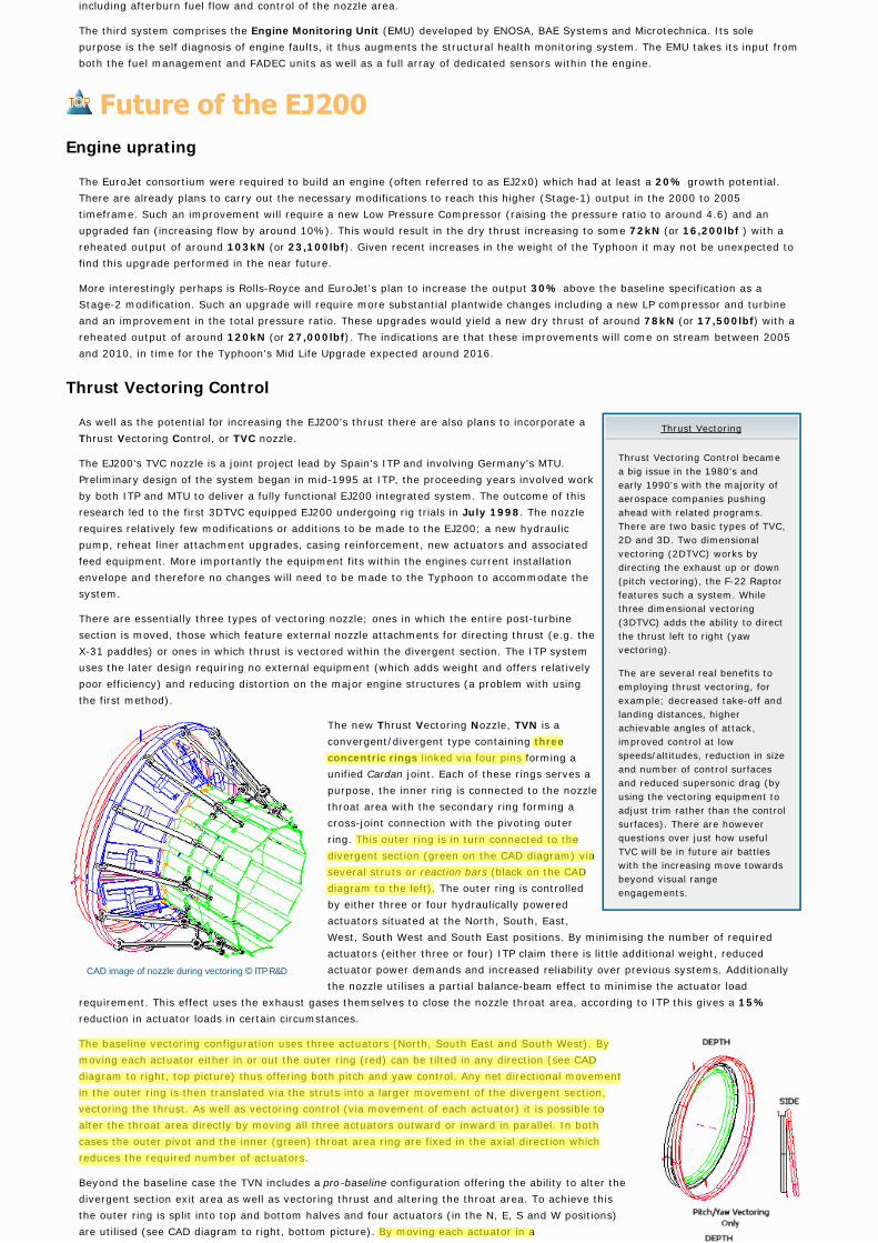
The new Thrust Vectoring Nozzle, TVN is a
convergent/divergent type containing three
concentric rings linked via four pins forming a
unified Cardan joint. Each of these rings serves a
purpose, the inner ring is connected to the nozzle
throat area with the secondary ring forming a
cross-joint connection with the pivoting outer
ring. This outer ring is in turn connected to the
divergent section (green on the CAD diagram) via
several struts or reaction bars (black on the CAD
diagram to the left). The outer ring is controlled
by either three or four hydraulically powered
actuators situated at the North, South, East,
West, South West and South East positions. By minimising the number of required
actuators (either three or four) ITP claim there is little additional weight, reduced
actuator power demands and increased reliability over previous systems. Additionally
the nozzle utilises a partial balance-beam effect to minimise the actuator load
requirement. This effect uses the exhaust gases themselves to close the nozzle throat area, according to ITP this gives a 15%
reduction in actuator loads in certain circumstances.
The baseline vectoring configuration uses three actuators (North, South East and South West). By
moving each actuator either in or out the outer ring (red) can be tilted in any direction (see CAD
diagram to right, top picture) thus offering both pitch and yaw control. Any net directional movement
in the outer ring is then translated via the struts into a larger movement of the divergent section,
vectoring the thrust. As well as vectoring control (via movement of each actuator) it is possible to
alter the throat area directly by moving all three actuators outward or inward in parallel. In both
cases the outer pivot and the inner (green) throat area ring are fixed in the axial direction which
reduces the required number of actuators.
Beyond the baseline case the TVN includes a pro-baseline configuration offering the ability to alter the
divergent section exit area as well as vectoring thrust and altering the throat area. To achieve this
the outer ring is split into top and bottom halves and four actuators (in the N, E, S and W positions)
are utilised (see CAD diagram to right, bottom picture). By moving each actuator in a
Thrust Vectoring
Thrust Vectoring Control became
a big issue in the 1980's and
early 1990's with the majority of
aerospace companies pushing
ahead with related programs.
There are two basic types of TVC,
2D and 3D. Two dimensional
vectoring (2DTVC) works by
directing the exhaust up or down
(pitch vectoring), the F-22 Raptor
features such a system. While
three dimensional vectoring
(3DTVC) adds the ability to direct
the thrust left to right (yaw
vectoring).
The are several real benefits to
employing thrust vectoring, for
example; decreased take-off and
landing distances, higher
achievable angles of attack,
improved control at low
speeds/altitudes, reduction in size
and number of control surfaces
and reduced supersonic drag (by
using the vectoring equipment to
adjust trim rather than the control
surfaces). There are however
questions over just how useful
TVC will be in future air battles
with the increasing move towards
beyond visual range
engagements.
CAD image of nozzle during vectoring © ITP R&D

unified/combined manner the thrust can be vectored and the throat area altered. However by moving
just the N and S actuators the split ring hinge can be opened and closed. In turn this moves the
upper and lower strut series either in or out opening or closing the exit area. In a traditional Con-Di
nozzle the exit area is directly related to the throat area. The problem with this approach is that it is
extremely difficult to optimise the nozzle shape to different flight profiles, e.g. subsonic cruise,
supersonic dash. By allowing dynamic control of the exit area the nozzle shape can be altered on the
fly. According to ITP this allows for significant improvements in achievable thrust in all flight profiles.
The three ring system is not the only unique feature of the nozzle. In previous convergent/divergent
systems the reaction bars or struts have been connected to the divergent section at a single point.
This limits their deflection range thus imposing limits on achievable thrust vectoring (typically to no
more than 20°). The ITP TVN however uses a dual point hinged connection allowing a far greater
range of movement to be achieved (according to ITP, studies indicate 30°+ can be achieved). By
careful placement of the struts, problems with the nozzle petals overlapping or colliding are also
removed.
Since rig trials commenced in 1998 the TVC equipped EJ200-01A has run for 80
hours (February 2000) of which 15 hours were at full reheat (including sustained
five minute burns) during 85 runs. These trials have included over 6700 vectoring
movements at the most severe throttle setting and 600 throttling cycles under the
most demanding vectoring conditions. These trials demonstrated full, 360°
deflection angles of 23.5° with a slew rate (the rate at which the nozzle can be
directed) of 110°/s and a side force generation of some 20kN (equal to
approximately to one third of the total EJ200 baseline output). These vectoring
trials have included both programmed ramp movements and active joystick control.
The studies have also verified the MTU developed DECU (Digital Engine Control
Unit) software and FCS connections.
During the summer of 2000 a round of altitude trials commenced at the University of
Stuttgart, Germany. These are focused on determining the effects of temperature
and pressure variation on the nozzle materials, shape and performance.
Additionally ITP are continuing work on further reducing the weight of the system.
In November 2000 ITP announced that an agreement had been reached with
Germany and the U.S. to utilise the X-31 VECTOR test aircraft for flight trials of the
nozzle. This will see a modified EJ200/TVN combination fitted to the X-31. The
modification work required will involve all members of the EuroJet consortium.
Additional input is likely from EADS and Boeing as well as NETMA in providing the
required EJ200's and equipping the X-31. The Spanish government has agreed to
pay for flight certification of the system and provide test pilots. The first flight trials
are expected in late 2002 to early 2003. In addition Eurofighter and EuroJet have
expressed a desire to commence flight trials of DA1 equipped with the nozzle sometime from 2003. How this fits in with the X-31 test
phase is currently unclear.
ITP have suggested that a Eurofighter fitted with the nozzle will benefit in a number of areas including; reduced after body drag
(through tighter nozzle shape control), an estimated 7% improvement in installed thrust for the supersonic cruise regime (M1.2 non-
reheat at 35000ft) and a 2% improvement in maximum take-off thrust.
At this stage there are no definite plans to fit the nozzle to any production Eurofighter. However Eurofighter, EuroJet and a number
of consortium nations and other companies have indicated a desire to include the nozzle (if possible) in Tranche-3 aircraft (due from
2010). This would fit with the stated desire of the four consortium nations to incorporate new technologies in sucessive Eurofighter
production runs. The current Eurofighter struture has already been strengthened in anticipation of increased loads created by TVC
as well as higher output EJ2x0 series powerplants.
The webmasters would like to express their thanks to ITP R&D for providing the information and material on the 3DTVC nozzle and Rolls Royce
for material on the XG-40 and EJ200.
Sources :
[1] : Rolls-Royce Online
[2] : Rolls-Royce, Press Office, Derby
[3] : EuroJet GmbH, Public Relations
[4] : Janes All the Worlds Aircraft 1996/97
[5] : Janes Avionics 96/97
[6] : Eurofighter 2000, Hugh Harkins, Key Publishing, 1997
[7] : Defence Data On-Line
[8] : DASA technical paper, Military Technology, December 1997
[9] : Engineering Materials 1, M. F. Ashby and D. R. H. Jones, Pergamon Press
[10] : Industria de Turbo Propulsores S.A., Spain
[11] : Smiths Industries plc.
[12] : Flight International, 16-22 June 1999
[13] : Bill Sweetman, World Air Power Journal, 38
[14] : EADS NV, Military Aircraft Division, Munich, Germany
Vectoring configurations © ITP R&D
Click either image for alternative versions
Rig trials of 3DTVC equipped EJ200 © ITP R&D
Cockpit | Defences | Flight Systems | Sensors | Structure | Weapons
History | News | Production | Squadron service | Main Index
All the source and data on this site is subject to copyright. Please read the disclaimer for more information
and contact the webmasters with any queries.