(iv b.tech -i sem a & b) jbiet dept it prakash p.pdfdepartment of information technology case...
TRANSCRIPT

Department of Information Technology
CASE TOOLS & SOFTWARE TESTING
LAB MANUALS
(IV B.tech -I Sem A & B)
PRAKASH P Asst. Professor
J.B.Institute of Engineering & Technology Yenkapally, Moinabad(Mandal)
Himathnagar(post),Hydreabad
JBIE
T
Dept o
f IT

2
INDEX
Sl.No. NAME OF THE PROGRAM Page No
1 Introduction to UML 3
2 Overview of UML diagrams 3-16
3 UML diagrams for ATM System 17-26
Sl.No NAME OF THE PROGRAM Page
No
1
Write Programs in ‘C’ Language to demonstrate the working of the following constructs:
i) do…while ii) while..do iii) if..else iv) switch v) for
27-31
2 “A program written in ‘C’ Language for Matrix Multiplication fails “Introspect the causes for its failure and write down the possible reasons for its failure.
32-33
3 Take any system (e.g. ATM system) and study its system specifications and report the various bugs. 34-37
4 Create a Test Plan document for any application (e.g. Library Management System). 38-44
5 Study of any test management tool (e.g. Test Director) 45-114
6 Study of any testing tool (e.g. Win Runner) 115-
127 7
Write the test cases for any known application (e.g. Banking Application) 127
JBIE
T
Dept o
f IT

3
UML (Unified Modeling Language)
UML is a language for visualizing, specifying, constructing and documenting the artifacts of a software
intensive system.
UML is simply another graphical representation of a common semantic model. UML provides a comprehensive
notation for the full lifecycle of object-oriented development.
Advantages:
• To represent complete systems (instead of only the software portion) using object-oriented
concepts
• To establish an explicit coupling between concepts and executable code
• To take into account the scaling factors that are inherent to complex and critical systems
• To creating a modeling language usable by both humans and machines
UML defines several models for representing systems:
• The class model captures the static structure
• The state model expresses the dynamic behavior of objects.
• The use case model describes the requirements of the user.
• The interaction model represents the scenarios and messages flows
• The implementation model shows the work units
• The deployment model provides details that pertain to process allocation
UML Diagrams
UML defines nine different types of diagram:
1. Use case diagrams: represent the functions of a system from the user's point of view.
2. Class diagrams : represent the static structure in terms of classes and relationships
3. Object diagrams : represent objects and their relationships and correspond to simplified
collaboration diagrams that do not represent message broadcasts.
4. Sequence diagrams: are a temporal representation of objects and their interactions.
5. Collaboration diagrams: spatial representation of objects, links, and interactions.
JBIE
T
Dept o
f IT

4
6. State chart diagrams : represent the behavior of a class in terms of states at run time.
7. Activity diagrams: represent the behavior of an operation as a set of actions
8. Component diagrams: represent the physical components of an application
9. Deployment diagrams: represent the deployment of components on particular pieces
of hardware
The different types of diagrams defined by UML
Relationship among various UML Diagrams in OOAD ( Object Oriented Analysis and design) is illustrated in
the following diagrams of Business Model, Use Case Diagram , Sequence Diagram , Class Diagram and Code
generation..
JBIE
T
Dept o
f IT

5
1. Use Case Diagram:
Use Cases for ATM
System:
Use Case Specification:
• A flow of events document is created for each use cases
• Written from an actor point of view
• Details what the system must provide to the actor when the use cases is executed
• Typical contents
o How the use case starts and ends
o Normal flow of events
o Alternate flow of events
o Exceptional flow of events
JBIE
T
Dept o
f IT

6
2. Class Diagram:
Class: A Class is represented like this:
Class Attribute1 Attribute2 MethodA() MethodB()
The top part showing the class name, the second showing the attributes and the third showing
the methods.
Object: An object looks very similar to a class, except that its name is underlined:
AnObject Attribute1 Attribute2 MethodA() MethodB()
Relationships:
Relationships between classes are generally represented in class diagrams by a line or
an arrow joining the two classes. UML can represent the following, different types of object
relationships.
If A depends on B, then this is shown by a dashed arrow between A and B, with the
arrowhead pointing at B:
Association: An association between A and B is shown by a line joining the two classes:
JBIE
T
Dept o
f IT

7
Bidirectional:
If there is no arrow on the line, the association is taken to be bidirectional.
A unidirectional association is indicated like this:
Aggregation:
An aggregation relationship is indicated by placing a white diamond at the end of the association next
to the aggregate class. If Baggregates A, then A is a part of B, but their lifetimes are independent:
Composition:
Composition, on the other hand, is shown by a black diamond on the end of association next to the
composite class. If B is composed of A, then B controls the lifetime of A.
Multiplicity:
The multiplicity of a relationship is indicated by a number (or *) placed at the end of an association.
The following diagram indicates a one-to-one relationship between A and B:
JBIE
T
Dept o
f IT

8
A multiplicity can also be a range of values. Some examples are shown below:
1 One and only one
* Any number from 0 to infinity
0..1 Either 0 or 1
n..m Any number in the range n to m inclusive
1..* Any positive integer
Naming an Association
To improve the clarity of a class diagram, the association between two objects may be named:
Inheritance:
An inheritance (generalization/specialization) relationship is indicated in the UML by an arrow
with a triangular arrowhead pointing towards thegeneralized class.
If A is a base class, and B and C are classes derived from A, then this would be represented by the
following class diagram:
JBIE
T
Dept o
f IT

9
Multiple Inheritance
The next diagram represents the case where class C is derived from classes A and B:
JBIE
T
Dept o
f IT
10
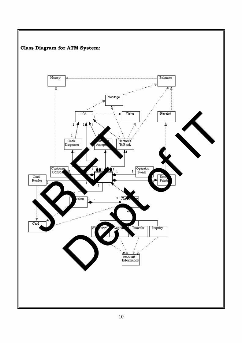
Class Diagram for ATM System:
JBIE
T
Dept o
f IT

11
Object Interactions :( Sequence and Collaboration : Complimentary to each other) diagrams.
Interactions between objects are represented by interaction diagrams –
both sequence and collaboration diagrams. An example of a collaboration diagram is shown below.
Objects are drawn as rectangles and the lines between them indicate links – a link is an instance of an
association. The order of the messages along the links between the objects is indicated by the
number at the head of the message:
Sequence diagrams show essentially the same information, but concentrate on the time-
ordered communication between objects, rather than their relationships. An example of a sequence diagram is
shown below. The dashed vertical lines represent the lifeline of the object:
4. Sequence Diagram:
Time ordered message passing:
JBIE
T
Dept o
f IT

12
Withdrawal Transaction Use Case
A withdrawal transaction asks the customer to choose a type of account to withdraw from (e.g. checking) from
a menu of possible accounts, and to choose a dollar amount from a menu of possible amounts. The system
verifies that it has sufficient money on hand to satisfy the request before sending the transaction to the bank. (If
not, the customer is informed and asked to enter a different amount.) If the transaction is approved by the bank,
the appropriate amount of cash is dispensed by the machine before it issues a receipt. (The dispensing of cash
is also recorded in the ATM's log.)
A withdrawal transaction can be cancelled by the customer pressing the Cancel key any time prior to choosing
the dollar amount.
5. Collaboration Diagram:
Relationship among Objects and Messages.
JBIE
T
Dept o
f IT
13
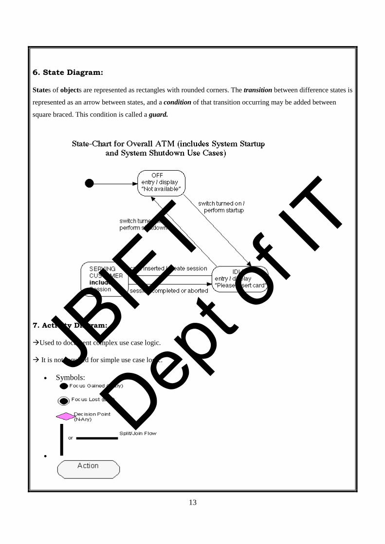
6. State Diagram:
States of objects are represented as rectangles with rounded corners. The transition between difference states is
represented as an arrow between states, and a condition of that transition occurring may be added between
square braced. This condition is called a guard.
7. Activity Diagram:
Used to document complex use case logic.
It is not required for simple use case logic.
• Symbols:
•
JBIE
T
Dept o
f IT

14
Use Case to accept credit Card Payment:
1. The customer then enters and submits her card details.
2. The system validates these values and either returns to the customer if there is an error or submits the payment to the Credit Card Service.
3. If the card payment is accepted, then the system notifies the customer of success. If not, then the error is logged, and the customer is notified of the failure (and perhaps directed to handle the payment some other way).
JBIE
T
Dept o
f IT

15
8. Component Diagrams:
Component diagrams describe software components and their relationships within
the implementation environment; they indicate the choices made at implementation time.
They may be simple files, or libraries loaded dynamically.
In C++, a specification corresponds to a file with a .h suffix, and a body corresponds to a file with the suffix .cpp.
JBIE
T
Dept o
f IT

16
9. Deployment Diagrams
Deployment diagrams show the physical layout of the various hardware components (nodes) that compose a
system, as well as the distribution of executable programs on this hardware.
Deployment diagrams may show node classes or node instances. As with other types of diagram, the graphical
difference between classes and objects is implemented by underlining the object name. The following example
shows the deployment diagram of a building access management system:
The diagram describes the nature of the communication links between the various nodes. The server and the
PCs are connected via an IPX link; the X-terminals and the server communicate via TCP/IP. The nature of the
connections between other nodes is not specified.
Each process named in the deployment diagram executes a main program with the same name as the one
described within the component diagram.
JBIE
T
Dept o
f IT

17
ATM System
Theory :-
Recently, because of the ongoing importance of globalization procedure, banking sector
is in enormous use by the public all over the world. Traditional system of withdrawing the money in
the bank is a long procedure and cannot be applicable in this fast pacing world. So, there arose a need
for withdrawal of money any time and any where .The system that allows this is nothing but ATM
system.
In this system, generally customer go to the ATM center and there in the ATM system he
inserts card and enter his pin no to prove his identity. Next he enters the amount to be withdrawn .If
balance is available he will get the desired amount.
JBIE
T
Dept o
f IT

18
Use Case Diagram: Aim:- To implement ATM system through Use Case Diagram. Procedure:- Step1: First an actor is created and named as user.
Step2: Secondly a system is created for ATM.
Step3: A use case Withdraw money is created and connected with user a association relationship.
Step4: Similarly various use cases like Deposit money, check balance, transfer money etc are created and appropriate relationships are associated with each of them. Static aspects:-
In UML the static aspects of this view are represented through use case diagrams.
JBIE
T
Dept o
f IT

19
Class Diagram:
Aim:- To implement ATM system through Class Diagram. Procedure:- Step1: First 3 packages are created.
Step2: In package1 ATM, cash dispenser, card controller, ATM controller classes are created.
Step3: In pack2 consortium, bank consortium class is created.
Step4: In pack3 bank, account and bank classes are created.
Step5: Appropriate relationships are maintained between them.
Class Diagram:
JBIE
T
Dept o
f IT

20
Sequence Diagram: Aim :- To implement ATM system through Sequence Diagram. Procedure:- Step1: First An actor is created and named as user.
Step2: Secondly an object is created for ATM.
Step3: Timelines and lifelines are created automatically for them.
Step4: In sequence diagram interaction is done through time ordering of messages. So
appropriate messages are passed between user and ATM as shown in the figure.
Dynamic Aspects:-
In UML the dynamic aspects of use case view are implemented through interaction diagrams
that are sequence diagram and collaboration diagram, state chart diagrams and activity diagrams.
All those diagrams are implemented here.
JBIE
T
Dept o
f IT

21
Sequence Diagram:
Collaboration Diagram: Aim :- To implement ATM system through Collaboration Diagram. Procedure:- Step1: First an actor is created and named as user.
Step2: Secondly an object is created for ATM.
Step3: In collaboration diagram interaction is done through organization.
Step4: So appropriate messages are passed between user and ATM as shown in the figure.
JBIE
T
Dept o
f IT

22
Collaboration Diagram:
JBIE
T
Dept o
f IT

23
State Diagram:
Aim :- To implement ATM system through State Diagram. Procedure:- Step1: First after initial state control undergoes transition to ATM screen.
Step2: After inserting card it goes to the state wait for pin.
Step3: After entering pin it goes to the state account verification.
Step4:.In this way it undergoes transitions to various states and finally reaches the ATM screen state as shown in the fig.
State Diagram:
JBIE
T
Dept o
f IT

24
Activity Diagram: Aim:- To implement ATM system through Activity Diagram. Procedure:- Step1: first initial state is created.
Step2: After that it goes to the action state insert card.
Step3: Next it undergoes transition to the state enter pin
Step4: In this way it undergoes transitions to the various states.
Step5: Use forking and joining wherever necessary.
Activity Diagram:
JBIE
T
Dept o
f IT

25
Component Diagram:
Aim:- To implement ATM system through Component Diagram. Procedure:- Step1: First user component is created.
Step2: ATM system package is created.
Step3: In it various components withdraw money, deposit money, check balance, transfer money etc are created.
Step4: Association relationship is established between user and other components.
Component Diagram:
JBIE
T
Dept o
f IT

26
Deployment Diagram:
Aim:- To implement ATM system through Deployment Diagram. Procedure:- Step1: First user node is created
Step2: various nodes withdraw money, deposit money, check balance, transfer money etc are created.
Step3: Association relationship is established between user and other nodes.
Step4: Dependency is established between deposit money and check balance.
Deployment View:
JBIE
T
Dept o
f IT

27
Step 7: After we click the install button on the previous window the following windows are opened
Step 8: Finally the following window is displayed. Click on finish to finish the installation.
JBIE
T
Dept o
f IT

28
7. Write a program using JSP to insert data into the database through Servlets and retrieving data from the database details.jsp import javax.servlet.*; import javax.servlet.http.*; import java.sql.*; import java.io.*; public class details extends HttpServlet { public void service(HttpServletRequest req,HttpServletResponse res) throws ServletException,IOException { res.setContentType("text/html"); PrintWriter out=res.getWriter(); String sname=req.getParameter("name"); out.println(sname); Connection con=null; try { Class.forName("sun.jdbc.odbc.JdbcOdbcDriver"); con=DriverManager.getConnection("jdbc:odbc:frnd"); PreparedStatement ps=con.prepareStatement("select * from sai where name=?"); ps.setString(1,sname); ResultSet rs=ps.executeQuery(); if(rs.next()) { out.println("Name: "+rs.getString(1)); out.println("RollNo: "+rs.getString(2)); out.println("Branch: "+rs.getString(3)); out.println(" Ph_No: "+rs.getString(4)); } } catch(Exception e) { e.printStackTrace(); }
JBIE
T
Dept o
f IT

29
finally { try { con.close(); } catch(Exception e) { } } } } web.xml
<web-app> <servlet> <servlet-name>details</servlet-name> <servlet-class>details</servlet-class> </servlet> <servlet-mapping> <servlet-name>details</servlet-name> <url-pattern>/detail</url-pattern> </servlet-mapping> </web-app>
register.jsp import javax.servlet.*; import javax.servlet.http.*; import java.sql.*; import java.io.*; public class register extends HttpServlet { public void service(HttpServletRequest req,HttpServletResponse res) throws ServletException,IOException { res.setContentType("text/html"); PrintWriter out=res.getWriter(); Connection con=null; String sname=req.getParameter("name"); String srollno=req.getParameter("rollno"); String sbranch=req.getParameter("branch"); String sphno=req.getParameter("phno"); System.out.println(sname); try { Class.forName("sun.jdbc.odbc.JdbcOdbcDriver"); con=DriverManager.getConnection("jdbc:odbc:frnd"); PreparedStatement ps=con.prepareStatement("insert into sai values(?,?,?,?)"); ps.setString(1,sname);
JBIE
T
Dept o
f IT

30
ps.setString(2,srollno); ps.setString(3,sbranch); ps.setString(4,sphno); int re=ps.executeUpdate(); ps.clearParameters(); } catch(Exception e) { e.printStackTrace(); } finally { try { con.close(); } catch(Exception e) { } } } } web.xml
<web-app> <servlet> <servlet-name>regs</servlet-name> <servlet-class>register</servlet-class> </servlet> <servlet-mapping> <servlet-name>regs</servlet-name> <url-pattern>/register</url-pattern> </servlet-mapping> </web-app>
JBIE
T
Dept o
f IT

31
AIM: Write Programs in ‘C’ Language to demonstrate the working of the following constructs
i) do…while ii) while..do iii) if..else iv) switch v) for
Program:
i) do..while
#include<stdio.h>
void main()
{
int x=0;
clrscr();
do{
x++;
printf("%d\n",x);
}
while(x<100);
getch();
}
Output: 0 1 2 3 4 5 6 7 8 9
JBIE
T
Dept o
f IT

32
ii) While Loop
#include<stdio.h> void main() { int x=0; clrscr(); while(x<6) { x++; printf("%d\n",x); } getch(); } Output: 1 2 3 4 5
iii) If …else
#include<stdio.h> void main() { int x; clrscr(); printf("Enter a number"); scanf("%d",&x); if(x%2==0)
JBIE
T
Dept o
f IT

33
printf("%d is an even number",x); else printf("%d is an odd number",x); getch(); } Output: Enter a number 5 5 is an odd number iv) Switch Case
#include<stdio.h> #include<conio.h> void main() { int a,b; char c; clrscr(); printf("enter the first number"); scanf("%d",&a); printf("enter the second number"); scanf("%d",&b); printf("Enter the operator"); scanf("%c",&c); switch(c)
JBIE
T
Dept o
f IT

34
{ case '+': { printf("%d",a+b); break; } case '-': { printf("%d",a-b); break; } case '*':{ printf("%d",a*b); break; } case '/': { printf("%d",a/b); break; } case '%': { printf("%d",a%b); break; } default: printf("Enter a valid arithmetic operator"); } getch();
JBIE
T
Dept o
f IT

35
} Output: Enter the first number: 15
Enter the second number: 10 Enter the operator: + 25
v) For Loop
#include<stdio.h> void main() { int i=1; clrscr(); for(i=1;i<=10;i++) { printf("%d\t",i); } getch(); } Output: 1 2 3 4 5 6 7 8 9 10
JBIE
T
Dept o
f IT

36
AIM: A program written in ‘C’ Language for Matrix Multiplication fails “Introspect the causes for its failure and write down the possible reasons for its failure.
Program:
#include<stdio.h> void main() { int a[3][3]={1,0,0,0,1,0,0,0,1}; int b[3][3]={9,8,7,6,5,4,3,2,1}; int c[3][3]; int i=0,j=0,k=0; clrscr(); for(i=0;i<3;i++) { for(j=0;j<3;j++) { c[i][j]=0; for(k=0;k<3;k++) { c[i][j]=c[i][j]+a[i][k]*b[k][j]; } } }
JBIE
T
Dept o
f IT

37
for(i=0;i<3;i++) { for(j=0;j<3;j++) { printf("%d\t",c[i][j]); } printf("\n"); } getch(); } Output: 9 8 7
6 5 4 3 2 1
JBIE
T
Dept o
f IT

38
AIM: Take any system (e.g. ATM system) and study its system specifications and report the various bugs.
Program:
Features to be tested:
1. Validity of the card.
2. Withdraw Transaction flow of ATM.
3. Authentication of the user’s.
4. Dispense the cash from the account.
5. Verify the balance enquiry.
6. Change of PIN number.
Bugs Identified:
Bug-Id Bug Name ATM_001 Invalid Card ATM_002 Invalid PIN ATM_003 Invalid Account type ATM_004 Insufficient Balance ATM_005 Transaction Limit ATM_006 Day limit ATM_007 Invalid money denominations ATM_008 Receipt not printed ATM_009 PIN change mismatch
Bug Report:
Bug Id: ATM_001 Bug Description: Invalid card Steps to reproduce: 1. Keep valid card in the ATM. Expected Result: Welcome Screen Actual Result: Invalid card Status : Pass/Fail
JBIE
T
Dept o
f IT

39
Bug Id: ATM_002 Bug Description: Invalid PIN entered Steps to reproduce: 1. Keep a valid card in ATM. 2. Enter the authorized PIN. 3. Menu screen should be displayed. Expected Result: Menu screen displayed Actual Result: Invalid PIN screen is displayed Status : Pass/Fail
Bug Id: ATM_003 Bug Description: Invalid Account type selected. Steps to reproduce: 1. Enter a valid user PIN number. 2. Select the withdraw option on the main menu. 3. Choose the correct type of account (either savings or current account). Expected Result: Enter the Amount screen displayed Actual Result: Invalid Account type screen is displayed. Status : Pass/Fail
Bug Id: ATM_004 Bug Description: Insufficient Balance Steps to reproduce:
1. Menu screen should be displayed.
2. Select the withdraw option.
3. Select the correct type of account.
4. Enter the sufficient amount to withdraw from the account.
5. Dispense the cash screen & amount to be deducted from account
Expected Result: Collect the amount screen displayed Actual Result: Insufficient balance in the account Status : Pass/Fail
JBIE
T
Dept o
f IT

40
Bug Id: ATM_005 Bug Description: Withdraw Limit per transaction. Steps to reproduce:
1. Menu screen should be displayed.
2. Select the withdraw option.
3. Select the correct type of account.
4. Enter sufficient amount to withdraw from the account Transaction within the limit.
5. Dispense the cash screen & amount to be deducted from account.
Expected Result: Cash is dispensed and collect the receipt Actual Result: Transaction limit exceeded screen is displayed Status : Pass/Fail
Bug Id: ATM_006 Bug Description: Withdraw limit per day Steps to reproduce:
1. Keep a valid card in ATM.
2. Enter the authorized PIN.
3. Enter the amount to withdraw from the account.
4. Amount enter is over the day limit (>40000)
5. Amount enter is over the day limit and display screen is displayed.
Expected Result: Cash is dispensed and collect the receipt. Actual Result: Day limit exceeded screen is displayed. Status : Pass/Fail
Bug Id: ATM_007 Bug Description: Amount enter denominations Steps to reproduce:
1. Keep a valid card in ATM.
2. Enter the authorized PIN.
3. Enter the amount which should be in multiples of 100.
4. Cash Dispenser screen is displayed.
Expected Result: Collect the amount screen is displayed. Actual Result: Amount enter not in required denominations.
JBIE
T
Dept o
f IT

41
Status : Pass/Fail
Bug Id: ATM_008 Bug Description: Statement not printed Steps to reproduce:
1. Keep a valid card in ATM.
2. Enter the authorized PIN.
3. Select the mini statement.
4. Current balance is displayed on the screen.
5. Collect printed receipt of the statement.
Expected Result: Collect the mini statement receipt Actual Result: receipt not printed. Status : Pass/Fail
Bug Id: ATM_009 Bug Description: PIN mismatch Steps to reproduce:
1. Keep a valid card in ATM.
2. Enter the authorized PIN.
3. Select the change PIN option on the menu.
4. Enter the current PIN.
5. Enter the new PIN.
6. Retype the new PIN
7. PIN successfully changed displayed on the screen.
Expected Result: PIN change successful. Actual Result: PIN mismatched due to wrong PIN entered Status : Pass/Fail
JBIE
T
Dept o
f IT

42
AIM: Create a Test Plan document for any application (e.g. Library Management System).
Program
Document Control Prepared by: Prabhu Designation: Student Date: Signature:
Reviewed by: Ch.Srinivasulu Designation: Date: Signature:
Approved by: Designation: Date: Signature:
Change History
Date Versio
n Section Description of the
Change Author
NA NA NA NA NA
JBIE
T
Dept o
f IT

43
Table of contents.
1. Purpose ..................................................................................................................... 44
1.1. Test Scope ......................................................................................................... 44
1.2. Test Milestones ................................................................................................. 44
2. Project Document References ................................................................................ 45
3. Entry Criteria .......................................................................................................... 45
3.1 Integration Testing ........................................................................................ 45
3.2 System Testing .............................................................................................. 45
3.3 Pre-Acceptance Testing ................................................................................ 45
4. Test Strategy ............................................................................................................ 45
4.1 Integration Testing ........................................................................................ 45
4.1.1 <Type Of Testing> ........................................................................................ 45
4.2 System Testing .............................................................................................. 46
4.2.1 <Type Of Testing> ........................................................................................ 46
5. Exit Criteria ............................................................................................................. 46
5.1 Integration Testing ........................................................................................ 46
5.2 System Testing .............................................................................................. 46
5.3 Pre-Acceptance Testing ................................................................................ 46
6. Defect Fixing Threshold Time................................................................................ 46
7. Test Coverage Criteria ........................................................................................... 46
8. Suspension and Resumption Criteria .................................................................... 46
9. Test Environments .................................................................................................. 46
8.1 Hardware Environment: ................................................................................ 46
8.2 Software Environment: ................................................................................. 46
10. Testing Tools: ...................................................................................................... 46
11. Test Reports ......................................................................................................... 47
12. Test Scheduling & Resource Planning .............................................................. 47
5.1 Scheduling ......................................................................................................... 47
5.2 Training Needs .................................................................................................. 48
13. Inter-Group coordination ................................................................................... 48
14. Metrics Plan ......................................................................................................... 48
JBIE
T
Dept o
f IT

44
Revision History
Date Version Description of the
section modified Change register ID
Author
NA NA NA NA Prabhu
Inputs Check List Document Submitted (Yes/No) NA NA
Approvals Authorization NA Test Manager NA Project Manager NA Client NA
1. Purpose To test the library management system functionality.
1.1. Test Scope To verify the functionality of the different features in the library management system
1.2. Test Milestones S. No Activity Output Date
<dd/mmm/yyyy> 1. Test Planning Test Plan 1 week 2. Pre-Acceptance test case designing Pre-Acceptance test
case specification 2 weeks
3. System test case designing System test case specification
3 weeks
4. Integration test case designing Integration test case specification
2 weeks
5. Execute Integration Test cases Integration test report
1 week
6. Execute System Test cases System test report 1 weeks 7. Execute Pre-Acceptance Test cases Pre-Acceptance test
report 1 week
JBIE
T
Dept o
f IT

45
2. Project Document References
3. Entry Criteria
3.1 Integration Testing
3.2 System Testing
3.3 Pre-Acceptance Testing
4. Test Strategy Test Types Required (Yes/No)
Integration Testing Functional Testing YES
System Testing Functional Testing YES Performance Testing NO Load Testing NO Stress Testing NO GUI Testing YES Pre-Acceptance Testing Functional Testing YES Performance Testing NO Load Testing NO Stress Testing NO GUI Testing YES
4.1 Integration Testing
4.1.1 Type of Testing: Functional testing
Test Objective: VERIFYING THE LIBRARY MANAGEMENT SYSTEM
Technique: Black box testing
Completion Criteria: NA
Special Considerations: NA
JBIE
T
Dept o
f IT

46
4.2 System Testing
4.2.1 Type Of Testing :
Test Objective:
Technique:
Completion Criteria:
Special Considerations:
5. Exit Criteria
5.1 Integration Testing
5.2 System Testing
5.3 Pre-Acceptance Testing
6. Defect Fixing Threshold Time Defect Type Severity Threshold Integration Testing Critical S1 NA Major S2 NA Minor S3 NA System Testing Critical S1 NA Major S2 NA Minor S3 NA
7. Test Coverage Criteria: Top-down approach
8. Suspension and Resumption Criteria: NA
8.1 Hardware Environment: ram, h/d,
8.2 Software Environment: Visual Basic-front end, MS- Access- backend, os, testing tools (Test Director)
9. Test Environments
JBIE
T
Dept o
f IT

47
10. Testing Tools:
S.NO Testing Type & Level
Tool Remarks
01 Functional testing
Win Runner 8.2
02 Test management tool
Test Director 8.0 1. To upload the test plan.
2. Create the test scripts/ test cases.
3. Execute the test cases. 4. Reporting the defects. 5. Analyze the test
reports / results.
11. Test Reports Bug trends Traceability Matrix Status Reports
12. Test Scheduling & Resource Planning 5.1 Scheduling
Functional
Task Resource
Name Effort Schedule (dd/mmm/yyyy)
Estimated Actual Planned Start Dt.
Actual Start Dt.
Planned End Dt.
Actual End Dt.
Review Project Plan
30 man /hrs 35 man/hrs
Create test plan
Review Test Plan
Participate in peer review of SRS
Analyze SRS Design Pre-Acceptance test cases
Design System test cases
Participate in
JBIE
T
Dept o
f IT

48
peer review of HLDD Participate in peer review of LLDD
Analyze HLDD and LLDD
Design integration test cases
Execute integration test cases
Evaluate integration test reports
Update System cases
Execute system test cases
Evaluate system test reports
Execute Pre-Acceptance test cases
Evaluate Pre-Acceptance test reports
Create test closure report
5.2 Training Needs S.No Resource Name Training Needs Status
18 studnets Win Runner 8.2 In progress
13. Inter-Group coordination S. No Group Representative Name NA
14. Metrics Plan Traceability matrix
JBIE
T
Dept o
f IT

49
AIM: Study of any test management tool (e.g. Test Director).
TEST DIRECTOR
Mercury Test Director is an excellent tool for managing the testing process
effectively and allows you to deploy high-quality applications quickly and effectively by
providing a consistent, repeatable process for gathering requirements, planning and
scheduling tests, analysing results, and managing defects and issues.
Test Director supports high levels of communication and collaboration among IT teams.
Whether you are coordinating the work of many disparate QA teams, or working with a large,
distributed Centre of Excellence, this test management tool helps facilitate information
access across geographical and organization boundaries.
Using Test Director, multiple groups throughout the organisation can contribute to the quality
process:
* Business analysts define application requirements and testing objectives * Test managers and project leads design test plans and develop test cases * Test automation engineers create automated scripts and store them in the repository * QA testers run manual and automated tests, report execution results, and enter defects * Developers review and fix defects logged into the database * Project managers create application status reports and manage resource allocation * Product managers decide whether an application is ready to be released. The important features of Test Director are:
• It is a web based tool and hence it facilitates distributing testing.
• As testing the software is linked to the requirements of the software, it provides the
feature of linking the software requirements to the testing plan.
JBIE
T
Dept o
f IT

50
• It provides the features to document the testing procedures.
• It provides the features of scheduling the manual and automated tests-the testing can
be done during nighttimes or when the system load is less.
• It keeps history of all the test runs.
• It provides the feature of setting groups of machines to carry out testing.
• The audit trail feature allows keeping track of changes in the tests and test runs.
• It keeps a log of all defects found and the status of each bug can be changed by
authorized persons only.
• It provides the features of creating different users with different privileges.
• It generates test reports and analysis for the QA manager to decide when the
software can be released into the market.
There are 4 tabs in Test Director
1.Requirements
2.Test Plan
3.Test Lab
4.Defect
1. In requirements tab we will place the requirements of the application, through this
requirements we can map with test cases.
2. Test Plan- After uploading the test cases to the test director, the scripts will be placed in
test plan.
3. Test Lab- We can execute the test scripts in the Test Lab. we can change the status of
the script
4. Defect- We can raise the defect by using the Defects tab in Test Director.
JBIE
T
Dept o
f IT

51
Specifying Requirements
You begin the application testing process by specifying testing requirements.
In this phase you perform the following tasks:
Define Testing Scope Examine application documentation to determine your testing
scope—test goals, objectives, and strategies.
Create Requirements Build a requirements tree to define your overall testing requirements.
Detail Requirements For each requirement topic in the requirements tree, create a list of
detailed testing requirements. Describe each requirement, assign it a priority level, and add
attachments if necessary.
Analyze Requirements Specification Generate reports and graphs to assist in analyzing your testing requirements. Review your
requirements to ensure they meet your testing scope.
Planning Tests
You create a test plan based on your testing requirements.
In this phase you perform the following tasks:
Define Testing Strategy Examine your application, system environment, and testing
resources to determine your testing goals.
Define Test Subjects Divide your application into subjects or functions to be tested. Build a
test plan tree to hierarchically divide your application into testing units, or subjects.
Define Tests Determine the types of tests you need for each subject. Add a basic definition
of each test to the test plan tree.
Create Requirements Coverage
Link each test with a testing requirement(s).
Design Test Steps Develop manual tests by adding steps to the tests in your test plan tree.
Test steps describe the test operations and the expected outcome of each test. Decide which
tests to automate.
Automate Tests For tests that you decide to automate, create test scripts with a Mercury
Interactive testing tool, or a custom or third-party testing tool.
Analyze Test Plan Generate reports and graphs to assist in analyzing test planning data.
Review your tests to determine their suitability to your testing goals.
JBIE
T
Dept o
f IT

52
Running Tests
After you build a test plan tree, you run your tests to locate defects and assess quality.
In this phase you perform the following tasks:
.
Create Test Sets Define groups of tests to meet the various testing goals in your project.
These might include, for example, testing a new version or a specific function in an
application. Determine which tests to include in each test set.
Schedule Runs Schedule test execution and assign tasks to testers.
Run Tests Execute the tests in your test set automatically or manually.
Analyze Test Results View the results of your test runs to determine whether a defect has
been detected in your application. Generate reports and graphs to help analyze these
results.
Tracking Defects Locating and repairing application defects efficiently is essential to the testing process.
Defects can be detected and added during all stages of the testing process. In this phase
you perform the following tasks:
Add Defects Report new defects detected in your application. Quality assurance testers,
developers, project managers, and end users can add defects during any phase in the
testing process.
Review New Defects Review new defects and determine which ones should be fixed.
Repair Open Defects Correct the defects that you decided to fix.
Test New Build Test a new build of your application. Continue this process until defects are
repaired.
Analyze Defect Data Generate reports and graphs to assist in analyzing the progress of
defect repairs, and to help determine when to release the application.
JBIE
T
Dept o
f IT

53
Starting Test Director You start Test Director from your Web browser, using the Test Director URL.
To start Test Director: 1 Open the Test Director Options window. In your Web browser, type your Test Director URL:
http://<TestDirector server name>/<virtual directory name>/default.htm
The Test Director Options window opens.
JBIE
T
Dept o
f IT

54
2 Open Test Director.
Click the Test Director link.
The first time you run Test Director, the application is downloaded to your computer. Then,
each time you open Test Director, it automatically carries out a version check. If Test Director
detects a newer version, it downloads the latest version to your machine.
The Test Director Login window opens.
3 Select a domain. In the Domain list, select DEFAULT.
4 Select a project.
In the Project list, select TestDirector_Demo.
5 Log on to the project as a QA tester. In the User ID box, type one of the following user names: alice_td, cecil_td, or michael_td. Skip the Password box. A password was not assigned to any of the above user names.
Click the Login button.
Test Director opens and displays the module in which you were last working.
In the title bar, Test Director displays the project name and your user name.
JBIE
T
Dept o
f IT

55
The Test Director Window In the following exercise, you will explore the Test Director modules and their common
elements.
To explore the Test Director window: 1 Explore the Test Director modules. ➤ Click the Requirements tab. The Requirements module enables you to specify your
testing requirements. This includes defining what you are testing, defining requirement topics
and items, and analyzing the requirements.
➤ Click the Test Plan tab. The Test Plan module enables you to develop a test plan based
on your testing requirements. This includes defining goals and strategies, dividing your plan
into categories, developing tests, automating tests where beneficial, and analyzing the plan.
➤ Click the Test Lab tab. The Test Lab module enables you to run tests on your application
and analyze the results.
➤ Click the Defects tab. The Defects module enables you to add defects, determine repair
priorities, repair open defects, and analyze the data.
2 Explore the common TestDirector elements. All the TestDirector modules have common elements. For example, click the Requirements tab.
JBIE
T
Dept o
f IT

56
Each of the Test Director modules contains the following key elements:
➤ The Test Director toolbar is located directly above the Test Director project name. If the
toolbar is not visible, click the Show Toolbar button. The common Test Director toolbar is
accessible from all Test Director modules and contains the following buttons:
Back: Navigates back to your previous location in Test Director.
Forward: If you navigated back, enables you to navigate forward.
Home: Logs out and takes you to the Test Director Login window.
Check Spelling: Checks the spelling for the selected word or text box. If there are no errors,
a confirmation message opens. If errors are found, the Spelling dialog box opens and
displays the word together with replacement suggestions.
Spelling Options: Opens the Spelling Options dialog box, enabling you to configure the way
Test Director checks spelling.
Thesaurus: Opens the Thesaurus dialog box and displays a synonym, antonym, or related
word for the selected word. You can replace the selected word or look up new words.
Add Defect: Opens the Add Defect dialog box, enabling you to add a new defect.
Trace All Changes: Opens the Trace All Changes dialog box, enabling you to view
traceability alerts.
Help: Opens the Online Help and displays the help topic for the current context.
➤ The menu bar, located directly below the Test Director project name, displays the names
of menus from which you select commands.
➤ The module toolbar, located below the menu bar, contains buttons for frequently-used
commands in the current Test Director module.
➤ The Tools button, located on the upper-right side of the window, enables you to change
your user password and other user properties, open the Document Generator, and view
version information for each Test Director client component.
➤ The Help button, located on the upper-right side of the window, enables you to access
Test Director’s online resources.
➤ The Logout button, located on the upper-right side of the window, enables you to exit and
return to the Test Director Login window.
JBIE
T
Dept o
f IT

57
Specifying Testing Requirements You begin the testing process by specifying testing requirements in Test Director’s
Requirements module. Requirements describe in detail what needs to be tested in your
application and provide the test team with the foundation on which the entire testing process
is based.
You define the requirements in Test Director by creating a requirements tree. This is a
graphical representation of your requirements specification, displaying your requirements
hierarchically. You can group and sort requirements in the tree, monitor task allocation and
progress of requirements, and generate detailed reports and graphs.
After you create tests in the Test Plan module, you can link requirements to tests. Later, after
you begin logging defects, you can also associate requirements with defects. In this way, you
can keep track of your testing needs at all stages of the testing process. If a testing
requirement changes, you can immediately identify which tests and defects are affected, and
who is responsible for them.
In this we will describe about:
➤ Defining Requirements
➤ Viewing Requirements
➤ Modifying Requirements
➤ Converting Requirements
JBIE
T
Dept o
f IT

58
Defining Requirements In the following exercise, you will define requirements for testing the functionality of reserving
cruises in Mercury Tours.
To define a requirement: 1 Open the Test Director_Demo project. If the TestDirector_Demo project is not already open, log on to the project.
2 Display the Requirements module. Click the Requirements tab. The Requirements module displays the requirements tree.
3 Display the requirements tree in Document View. Make sure the Document View of the requirements tree is displayed
4 Create a new requirement. Click the New Requirement button. The New Requirement dialog box Opens
Type or select the following:
Name: Cruise Reservation
Product: Mercury Tours (HTML Edition)
Priority: 4-Very High
Type: Functional
Click OK. TestDirector adds the Cruise Reservation requirement to the requirements tree.
5 Add a child requirement. Click the New Child Requirement button to add the next requirement below
JBIE
T
Dept o
f IT
59
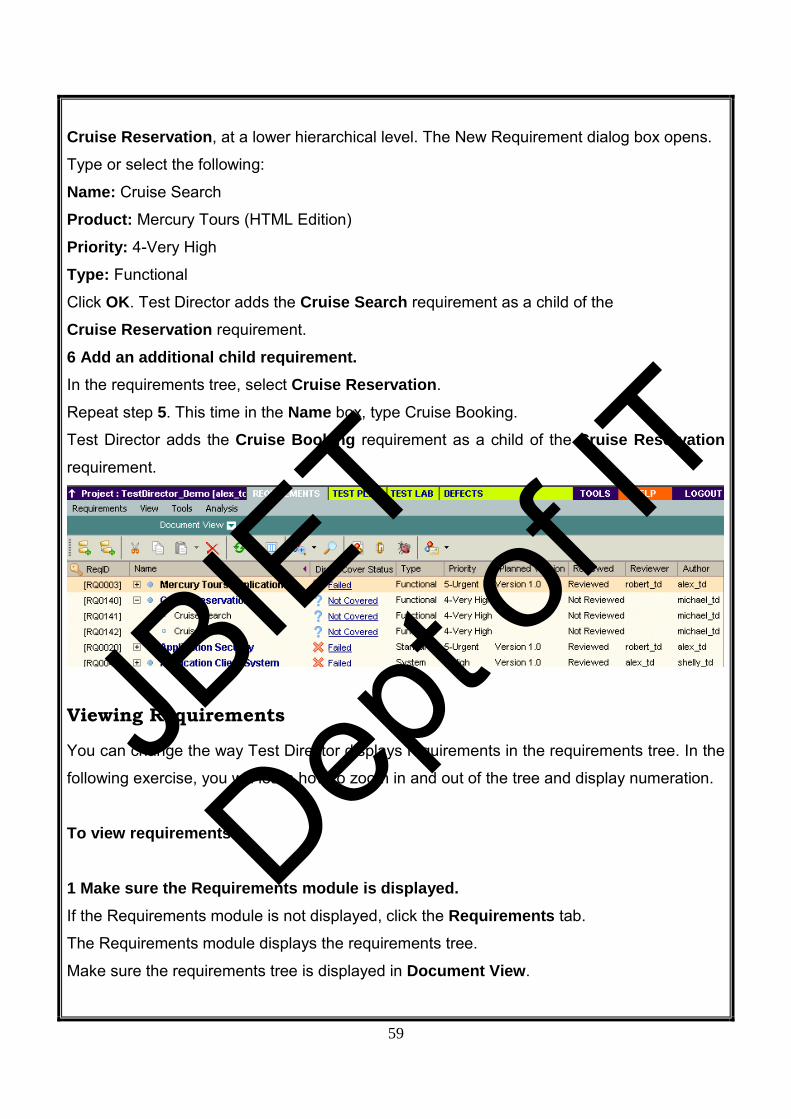
Cruise Reservation, at a lower hierarchical level. The New Requirement dialog box opens.
Type or select the following:
Name: Cruise Search
Product: Mercury Tours (HTML Edition)
Priority: 4-Very High
Type: Functional
Click OK. Test Director adds the Cruise Search requirement as a child of the
Cruise Reservation requirement.
6 Add an additional child requirement. In the requirements tree, select Cruise Reservation.
Repeat step 5. This time in the Name box, type Cruise Booking.
Test Director adds the Cruise Booking requirement as a child of the Cruise Reservation requirement.
Viewing Requirements You can change the way Test Director displays requirements in the requirements tree. In the
following exercise, you will learn how to zoom in and out of the tree and display numeration.
To view requirements: 1 Make sure the Requirements module is displayed. If the Requirements module is not displayed, click the Requirements tab.
The Requirements module displays the requirements tree.
Make sure the requirements tree is displayed in Document View.
JBIE
T
Dept o
f IT

60
2 Zoom in and out of the requirement. To zoom in, select Cruise Reservation in the requirements tree.
Click the Zoom In button on the toolbar. The requirements tree displays
only the Cruise Reservation child requirements.
To reverse the zoom in action and display the entire requirements tree, click the Zoom In arrow and choose Zoom Out To Root. 3 Display numerations in the requirements tree. To assign hierarchical numbers to each requirement in the tree, choose
View > Numeration. As you make changes to the tree, Test Director automatically
renumbers the requirements. Note that the numbers are not related to the unique Req ID
assigned to each requirement.
4 Remove the numeration from the requirements tree. To remove the hierarchical numbering, choose View > Numeration
JBIE
T
Dept o
f IT

61
Modifying Requirements
You can modify the requirements in the requirements tree. In the following exercise, you will
learn how to copy, rename, move, or delete requirements.
To modify requirements: 1 Make sure the Requirements module is displayed. If the Requirements module is not displayed, click the Requirements tab.
The Requirements module displays the requirements tree.
2 Copy a requirement. In the requirements tree, select Cruise Reservation and click the Copy button. Click the Paste button.
A warning box opens because you are duplicating the requirement name. Click OK.
The requirement is pasted below the selected requirement, at the same hierarchical level.
_Copy_ is added to the end of the requirement’s name.
3 Rename the Cruise Reservation_Copy_ requirement. Right-click the Cruise Reservation_Copy_ requirement and choose Rename.
Edit the requirement name to Hotel Reservation and press Enter. 4 Move the Hotel Reservation requirement to a different location in the requirements tree. Select Hotel Reservation.
Click the Cut button.
Select Reservations Management. To paste Hotel Reservation below the selected requirement, click the Paste arrow and
choose Paste as Child. Click Yes to confirm.
5 Delete the Hotel Reservation requirement.
JBIE
T
Dept o
f IT

62
Select Hotel Reservation.
Click the Delete button.
Click Yes to confirm. Test Director deletes the requirement and its children
Converting Requirements
After you create the requirements tree, you use the requirements as a basis for defining your
test plan tree in the Test Plan module
You can use the Convert to Tests wizard to assist you when designing your test plan tree.
The wizard enables you to convert selected requirements or all requirements in the
requirements tree to tests or subjects in the test plan tree.
In the following exercise, you will convert the Cruise Reservation requirement to a subject in
the test plan tree and the Cruise Reservation child requirements to tests. To convert a requirement: 1 Make sure the Requirements module is displayed. If the Requirements module is not displayed, click the Requirements tab.
The Requirements module displays the requirements tree.
2 Select a requirement. In the requirements tree, select Cruise Reservation.
3 Open the Convert to Tests wizard. Choose Tools > Convert to Test > Convert Selected. The Step 1 dialog box opens. JB
IET
Dept o
f IT

63
4 Choose an automatic conversion method. Select the second option, Convert lowest child requirements to tests, to convert the
selected requirements to tests.
5 Start the conversion process. Click Next to begin converting the requirements. When the conversion process is complete,
Test Director displays the results in the Step 2 dialog box.
JBIE
T
Dept o
f IT

64
6 Convert Cruise Search to a step and restore it. Select Cruise Search and click the Convert to Step button. Test Director converts the
Cruise Search test to a step. With Cruise Search selected, click the Convert to Test button. Test Director converts the Cruise Search step back to a test.
Click Next. The Step 3 dialog box opens. JBIE
T
Dept o
f IT

65
7 Choose the destination subject path. In the Destination Subject Path, click the browse button. The Select
Destination Subject dialog box opens. In the test plan tree, select the Cruises subject.
JBIE
T
Dept o
f IT

66
Click OK to close the Select Destination Subject dialog box. The Destination Subject Path box now indicates the following path:
8 Finalize the conversion process. Click Finish.
Click OK to confirm.
9 View the tests in the test plan tree. Click the Test Plan tab to display the Test Plan module.
In the test plan tree, select Cruises and click the Refresh Selected button.
The test plan tree displays Cruise Reservation under Cruises.
Expand Cruise Reservation. The test plan tree displays the Cruise Booking and Cruise Search manual tests.
Now that you are familiar with defining requirements, viewing and modifying the requirements
tree, and converting requirements “Planning Tests”. In Lesson 3, you will learn how to define
your test plan tree.
JBIE
T
Dept o
f IT

67
Planning Tests After you define your requirements, you need to determine your testing goals. To do this,
examine your application, system environment, and testing process to outline the testing
strategy for achieving your goals.
After you determine your testing goals, you build a test plan tree, which hierarchically divides
your application into testing units, or subjects. For each subject in the test plan tree, you
define tests that contain steps.
For each test step, you specify the actions to be performed on your application and the
expected result. You can increase the flexibility of a test step by adding parameters.
To keep track of the relationship between your tests and your requirements, you can add
links between them. By creating links, you ensure compliance with your requirements
throughout the testing process.
After you design your tests, you can decide which tests to automate. When you automate a
test, you can generate a test script and then complete it using other Mercury Interactive
testing tools (for example, Quick Test Professional, Astra Quick Test, or WinRunner).
In this we will describe about:
➤ Developing a Test Plan Tree
➤ Designing Test Steps
➤ Copying Test Steps
➤ Calling Tests with Parameters
➤ Creating and Viewing Requirements Coverage
➤ Generating Automated Test Scripts
JBIE
T
Dept o
f IT

68
Developing a Test Plan Tree The typical application is too large to test as a whole. The Test Plan module enables you to
divide your application according to functionality. You divide your application into units, or
subjects, by creating a test plan tree. The test plan tree is a graphical representation of your
test plan, displaying your tests according to the hierarchical relationship of their functions.
After you define subjects in the tree, you decide which tests to create for each subject and
add them to the tree.
we converted the Cruise Reservation requirement and its child requirements to subjects
and tests in the test plan tree. In the following exercise, you will add a subject and a test to
the test plan tree in the Test Plan module.
To develop a test plan tree: 1 Open the TestDirector_Demo project. If the TestDirector_Demo project is not already open, log on to the project.
2 Display the Test Plan module. Click the Test Plan tab.
3 Add a subject folder to the test plan tree. Select the Cruises subject folder and click the New Folder button.
The New Folder dialog box opens.
In the Folder Name box, type Cruise Cancellation. Click OK. The new subject folder appears
under the Cruises subject folder in the test plan tree.
In the Description tab in the right pane, type a description of the subject: This folder
contains tests that verify the Cancel Reservation functionality.
4 Add a test to the subject folder. Select Cruise Cancellation and click the New Test button. The Create New Test dialog box
opens.
JBIE
T
Dept o
f IT

69
In the Test Type box, select QUICKTEST_TEST to create a Quick Test Professional/Astra
Quick Test test, or select WR-AUTOMATED to create a WinRunner test.
Notes: ➤ The QUICKTEST_TEST test type is only available if you have installed the Quick Test
Professional/Astra Quick Test Add-in from the Test Director Addins page. For more
information on installing the add-in, refer to the Test Director Installation Guide.
➤ If you selected QUICKTEST_TEST from the Test Type list, the Template box is available.
You can create your new test based on another Quick Test Professional/Astra Quick Test
test, defined as a template test. Test Director copies the template test to your new test
without the test results.
In the Test Name box, type a name for the test: Cancel All Reservations.
Click OK. The Required Fields dialog box opens.
Select the following:
Level: Basic
Reviewed: Not Reviewed
Priority: 4-Very High
Click OK.
JBIE
T
Dept o
f IT

70
The new test is added to the test plan tree under the Cruise Cancellation subject folder.
5 Add a test description. In the Details tab, you can see the test name, test designer, creation date, test status, and
other information.
In the Description box, type a description for the test: The test verifies cancellation of cruise
reservations in the Itinerary page.
Designing Test Steps
After you add a test to the test plan tree and define basic test information, you define test
steps—detailed, step-by-step instructions that specify how to execute a test. A step includes
the actions to be performed on your application and the expected results.
You can create test steps for both manual and automated tests. For manual tests, you
complete test planning by designing the test steps. Using your plan, you can begin test
execution immediately. For automated tests, you create an automated test script using a
Mercury Interactive testing tool, a custom testing tool, or a third-party testing tool.
In the following exercise, you will create the Cruise Booking test. This test verifies the
process of booking a cruise through the Mercury Tours site.
To design a test step: 1 Make sure the Test Plan module is displayed. If the Test Plan module is not displayed, click the Test Plan tab.
2 Display the Cruise Booking test. Under the Cruise Reservation folder, select the Cruise Booking test.
3 Open the Design Step Editor. Click the Design Steps tab.
JBIE
T
Dept o
f IT

71
Click the New Step button. The Design Step Editor opens
In the Step Name box, Test Director displays a step name. The default name is the
sequential number of the test step (Step 1 if you are adding steps to a test for the first time).
4 Define a step for displaying the Cruise Special page. In the Design Step Editor, type the following:
Step Name: Display the Cruise Special page.
Description: Click the Cruises button.
Expected Result: The Cruise Special page opens. JBIE
T
Dept o
f IT

72
5 Define a step for reserving the cruise. In the Design Step Editor, click the New Step button. The Step Name box displays Step 2.
Type the following:
Step Name: Display the Cruise Reservation page.
Description: Click the Now Accepting Reservations button.
Expected Result: The Cruise Reservation page opens.
6 Define a step for booking the cruise. In the Design Step Editor, click the New Step button. The Step Name box displays Step 3.
Type the following:
Step Name: Book the cruise.
Description: Enter passenger name, credit card information, and address. Click OK.
Expected Result: The Cruise Confirmation page opens.
7 Define a step for printing the cruise confirmation information. In the Design Step Editor, click the New Step button. The Step Name box displays Step 4.
Type the following:
Step Name: Print cruise confirmation.
Description: Click the Print button.
Expected Result: A confirmation page is printed.
JBIE
T
Dept o
f IT

73
8 Define a step for logging off the Mercury Tours site. In the Design Step Editor, click the New Step button. The Step Name box displays Step 5.
Type the following:
Step Name: Log off.
Description: Click the Sign-Off button.
Expected Result: Returns to the Sign-On page.
9 Close the Design Step Editor. Click OK. The Design Steps tab displays the design steps.
Copying Test Steps
You can copy steps from another test in the same project or from a different project. In the
following exercise, you will copy the test steps from the Cruise Booking test and paste them
into the Cruise Search test.
To copy a test step: 1 Display the Design Steps tab for the Cruise Booking test. In the test plan tree, under Cruise Reservation, select the Cruise Booking test. Click the Design Steps tab.
JBIE
T
Dept o
f IT

74
2 Select the steps that you want to copy. Position the mouse pointer in the gray sidebar on the left. The mouse pointer changes to .
Press the Shift or Ctrl key and select all the steps.
3 Copy the selected steps. Click the Copy Steps button.
4 Paste the steps in the Cruise Search test. In the test plan tree, under Cruise Reservation, select the Cruise Search test.
In the Design Steps tab, click the Paste Steps button. Test Director copies the test steps to
the Design Steps tab.
Calling Tests with Parameters
When you design test steps, you can include a call to a manual test. When you run the test,
the test steps include the steps from the called test as part of the test. The test that you call
is a template test. This is a reusable test that can be called by other tests. A template test
can include parameters. A parameter is a variable that replaces a fixed value. You can
modify the value of a parameter according to the test that is calling it, or for various instances
of the same test.
For example, suppose you have a test which logs in a user with a specific password when
you start your application. You need to call this test at the beginning of each test. In some
cases, you may want to log on as a regular user while in other cases, you may want to log on
JBIE
T
Dept o
f IT

75
as the administrator. To accomplish this, you create two parameters, <<<user name>>> and
<<<password>>>, and modify the value of each parameter according to the type of test that
is calling your template test.
In the following exercise, you will enhance your test by calling the Connect And Sign-On test. This template test includes parameters for the Mercury Tours URL address and for the
user name and password used to log on to the site.
To call a test with parameters: 1 Display the Design Steps tab for the Cruise Booking test. In the test plan tree, under Cruise Reservation, select the Cruise Booking test. Click the Design Steps tab.
2 Select the test with parameters that you want to call. Click the Call to Test button. The Select a Test dialog box opens.
In the Find box, type Connect, and click the Find button. Test Director highlights the
Connect And Sign-On test.
Click OK. The Parameters of Test dialog box opens and displays the parameters contained
in the called test.
JBIE
T
Dept o
f IT

76
3 Assign values to the parameters. In the Value column, type the following:
mercury tours url: http://<TestDirector server name>/mtours/index.html password: Leave
blank. You will assign a value to this parameter when you run your test
user name: your user name
Note: You can also assign values to parameters when you create a test that calls your test,
when you add your test to a test set, or when you run your test.
Click OK. Test Director adds the Call Connect And Sign-On step to your design steps.
Test Director Tutorial
4 Reorder the steps. Position the mouse pointer on the gray sidebar to the left of the Call Connect And Sign-On step. The mouse pointer changes to. Click and drag the step to the top row.
JBIE
T
Dept o
f IT

77
5 Adjust the size of the steps. Click the Adjust Rows Height button. Test Director expands the size of the rows in which
the text is too long to view. Note that if you close and reopen the Design Steps tab, Test
Director restores the default step size.
Creating and Viewing Requirements Coverage
It is essential that the tests in your test plan comply with your testing requirements. To help
ensure compliance throughout the testing process, you can add links between your tests in
the Test Plan module and your requirements in the Requirements module.
In the Test Plan module, you create requirements coverage by selecting requirements to link
to a test. Alternatively, in the Requirements module, you create tests coverage by selecting
tests to link to a requirement. A test can cover more than one requirement, and a
requirement can be covered by more than one test.
To further ensure compliance with your testing requirements, after you log defects, you can
link your tests to defects .This ensures that if a requirement changes, you can identify which
tests and defects are affected, and who is responsible for them.
JBIE
T
Dept o
f IT

78
In the following exercises, you will create requirements coverage and tests coverage. You
will also view a graphic representation of tests coverage.
Linking Requirements to a Test In the following exercise you will view existing requirements coverage for the Cruise Booking test and create new requirements coverage by linking the View Reservations requirement to the Cruise Booking test.
To link a requirement to a test: 1 Make sure that the Test Plan module is displayed. If the Test Plan module is not displayed, click the Test Plan tab.
2 Display the Cruise Booking test. Under the Cruise Reservation folder, select the Cruise Booking test.
3 Display the Reqs Coverage tab. In the right pane, click the Reqs Coverage tab. Test Director displays the existing
requirements coverage in the coverage grid. Note that the Cruise Booking requirement is
already linked to the Cruise Booking test because
4 Display the requirements tree. Click the Select Req button to show the requirements tree on the right.
5 Search for the View Reservations requirement in the requirements tree. In the Find box, type View and click the Find button. Tes tDirector highlights the View Reservations requirement in the tree.
6 Add the requirement to the coverage grid.
JBIE
T
Dept o
f IT

79
Click the Add to Coverage (Include Children) button. Test Director adds the View Reservations requirement to the coverage grid.
Tip: You can also drag a requirement or requirement topic in the requirements tree to the
coverage grid.
7 Hide the requirements tree. Click the Close button.
Linking Tests to a Requirement In the following exercise, you will create tests coverage by linking the Cruise Search test to the Cruise Booking requirement.
To link a test to a requirement: 1 Display the Requirements module. Click the Requirements tab.
2 Display the requirements tree in Coverage View. Select the Coverage View of the requirements tree.
The Test Coverage tab is displayed in the right pane.
3 Display the Cruise Booking requirement. In the requirements tree, under Cruise Reservation, select the Cruise Booking requirement. Test Director displays the existing tests coverage in the coverage grid. Note
that the Cruise Booking test is already linked to the Cruise Booking requirement because
you generated the test from the requirement. 4 Display the test plan tree. In the Tests Coverage tab, click the Select Tests button to show the test plan tree on the
right.
JBIE
T
Dept o
f IT
80
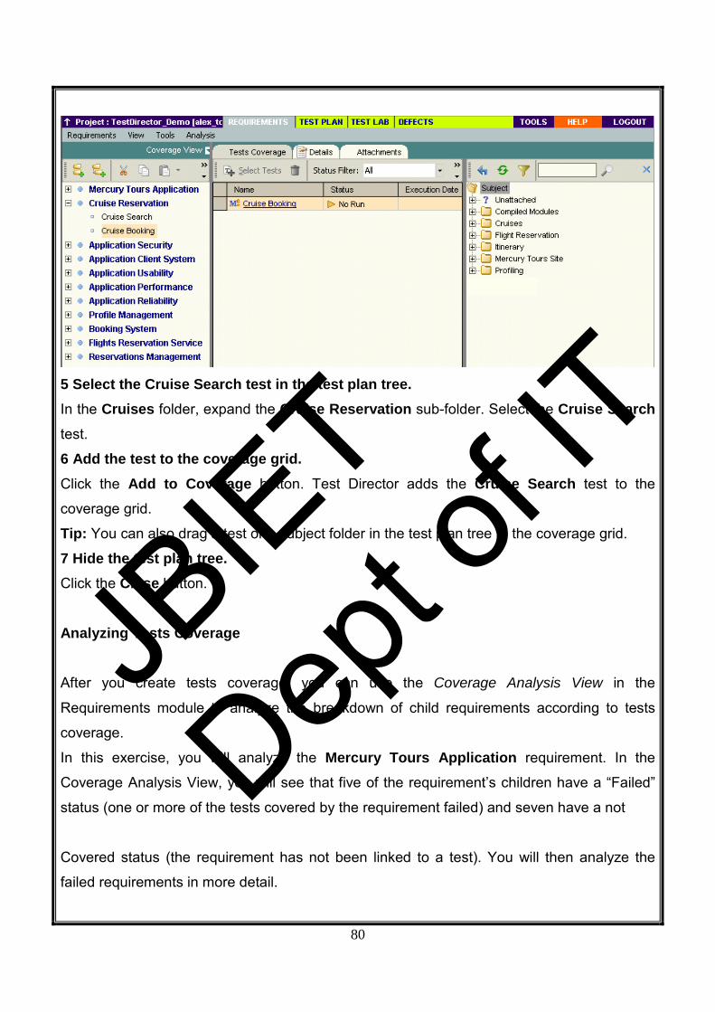
5 Select the Cruise Search test in the test plan tree. In the Cruises folder, expand the Cruise Reservation sub-folder. Select the Cruise Search test.
6 Add the test to the coverage grid. Click the Add to Coverage button. Test Director adds the Cruise Search test to the
coverage grid.
Tip: You can also drag a test or a subject folder in the test plan tree to the coverage grid.
7 Hide the test plan tree. Click the Close button.
Analyzing Tests Coverage
After you create tests coverage, you can use the Coverage Analysis View in the
Requirements module to analyze the breakdown of child requirements according to tests
coverage.
In this exercise, you will analyze the Mercury Tours Application requirement. In the
Coverage Analysis View, you will see that five of the requirement’s children have a “Failed”
status (one or more of the tests covered by the requirement failed) and seven have a not
Covered status (the requirement has not been linked to a test). You will then analyze the failed requirements in more detail.
JBIE
T
Dept o
f IT
81
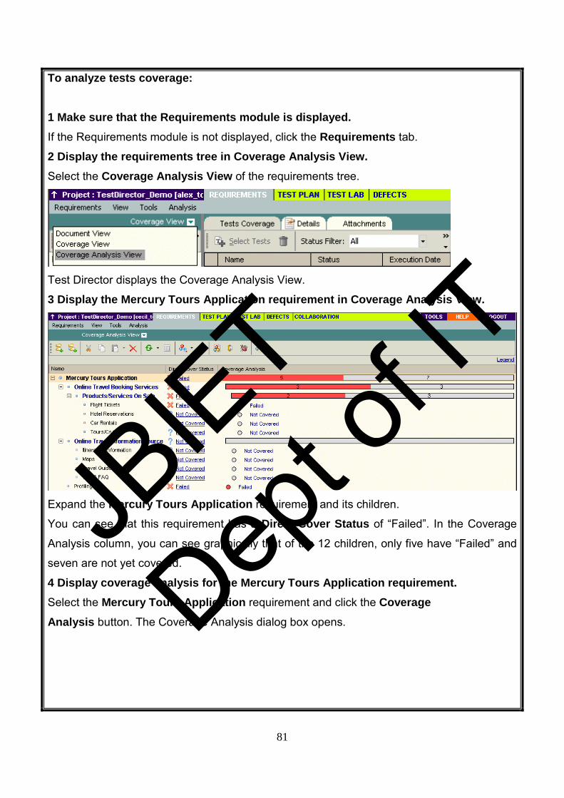
To analyze tests coverage: 1 Make sure that the Requirements module is displayed. If the Requirements module is not displayed, click the Requirements tab.
2 Display the requirements tree in Coverage Analysis View. Select the Coverage Analysis View of the requirements tree.
Test Director displays the Coverage Analysis View.
3 Display the Mercury Tours Application requirement in Coverage Analysis View.
Expand the Mercury Tours Application requirement and its children.
You can see that this requirement has a Direct Cover Status of “Failed”. In the Coverage
Analysis column, you can see graphically that of the 12 children, only five have “Failed” and
seven are not yet covered.
4 Display coverage analysis for the Mercury Tours Application requirement. Select the Mercury Tours Application requirement and click the Coverage Analysis button. The Coverage Analysis dialog box opens.
JBIE
T
Dept o
f IT

82
This graph displays the five “Failed” requirements in red and the seven “Not Covered”
requirements in gray.
5 Display the child requirements with a “Failed” status. Click the red Failed area of the graph. TestDirector lists the five child requirements with a
“Failed” status.
Note that you can select a requirement and click Go To highlight the requirement in the
requirements tree.
6 Display tests coverage for the requirement. Click the Show Tests Coverage link to extend the Coverage Analysis dialog box and display
the Tests Coverage Chart.
JBIE
T
Dept o
f IT

83
You can see, for example, that 19 of the tests associated with the Mercury Tours Application requirement have a “Failed” status. The Mercury Tours Application requirement’s direct cover status of “Failed” therefore means that 32.2% of the tests
associated with this requirement failed. Note that you can click a section of the chart to open
the Tests Coverage dialog box and display the list of tests with the selected status. 7 Close the Coverage Analysis dialog box. Click the Close button.
Generating Automated Test Scripts
Test planning involves deciding which tests to automate. If you choose to perform tests
manually, the tests are ready for execution as soon as you define the test steps. If you
choose to automate tests, you can generate test scripts and complete them using other
Mercury Interactive testing tools (for example, QuickTest Professional, Astra QuickTest, or
WinRunner). Consider the following issues when deciding whether to automate a test.
Do automate: • Tests that will run with each new version of your application to check the stability of basic
functionality across the entire application (regression test).
• Tests that use multiple data values for the same operation (data-driven tests).
• Tests that are run many times (stress tests) and tests that check a multi-user client/server
system (load tests).
JBIE
T
Dept o
f IT

84
Do not automate: • Tests that will be executed only once.
• Tests that require immediate execution.
• Tests that check how easy the application is to use (usability tests).
• Tests that do not have predictable results.
In the following exercise, you will generate an automated test script for the Cruise Search test.
To generate an automated test script: 1 Display the Test Plan module. Click the Test Plan tab.
2 Locate the Cruise Search manual test to automate. Select the Subject folder at the root of the test plan tree and click the Find Folder/Test button. The Find Folder/Test dialog box opens.
Do the following:
Value to Find: type: Cruise
Include Tests: Select this checkbox to instruct Test Director to search for folders and tests.
Click Find. The Search Results dialog box opens and displays a list of possible matches.
Select Cruises\Cruise Reservation\Cruise Search and click the Go To button to highlight
the test in the test plan tree.
Click Close to close the Search Results dialog box.
3 Display the Design Steps tab. In the right pane, click the Design Steps tab.
4 Generate a test script.
JBIE
T
Dept o
f IT

85
Click the Generate Script button.
Choose QUICKTEST_TEST to generate a QuickTest Professional or Astra QuickTest test,
or choose WR-AUTOMATED to generate a WinRunner test. TestDirector uses the steps in
the Cruise Search test to create an automated test script. In the test plan tree, note that the
manual test icon next to the test is now replaced with the automated test icon.
5 View the test script. Click the Test Script tab.
To display and modify your test script in the testing tool in which it was created, click the
Launch button.
Now that you are familiar with creating a test plan tree, designing test steps, copying test
steps, calling a test with parameters, linking tests to requirements, analyzing tests coverage,
and automating your manual tests.
Running Tests Running tests is the core of the testing process. As your application changes, you run manual and
automated tests in your project to locate defects and assess quality.
You start by creating test sets and choosing which tests to include in each set. A test set is a group of
tests in a Test Director project designed to achieve specific testing goals. Test Director enables you to
control the execution of tests in a test set by setting conditions and scheduling the date and time for
executing your tests.
After you define test sets, you can begin to execute your tests. When you run a test manually, you
execute the test steps you defined in test planning. You pass or fail each step, depending on whether
the actual results match the expected output. When you run a test automatically, Test Director opens
the selected testing tool, runs the test, and exports the test results to
Test Director.
In this lesson, you will learn about:
➤ Defining Test Sets
➤ Adding Tests to a Test Set
➤ Scheduling Test Runs
➤ Running Tests Manually
➤ Running Tests Automati
JBIE
T
Dept o
f IT

86
Defining Test Sets After you design tests in the Test Plan module, you create a test sets tree. A test sets tree
enables you to organize your testing process by grouping test sets in folders and organizing
them in different hierarchical levels in the Test Lab module. Test sets can include both
manual and automated tests. You can also include the same test in different test sets.
To decide which test sets to create, think about the testing goals you defined at the
beginning of the testing process. Consider issues such as the current state of the application
and the addition or modification of new features.
Following are examples of general categories of test sets you can create:
Sanity Tests the entire application at a basic level to check that it is functional and stable.
Normal Tests the system in a more in-depth manner than the sanity test. A Normal test set
can contain both positive and negative checks. Positive checks test that the application
responds to input as expected. Negative tests attempt to crash an application to demonstrate
that the application is not functioning properly.
Advanced Checks the entire application, including its most advanced features.
Regression Verifies that a change to one part of the application does not prevent the rest of
the application from functioning.
Function Tests a specific feature or a group of features in the application.
In the following exercise, you will define the Mercury Tours Site test set.
To define a test set: 1 Open the TestDirector_Demo project. If the TestDirector_Demo project is not already open, log on to the project.
2 Display the Test Lab module. Click the Test Lab tab.
3 Add a folder to the test sets tree. In the test sets tree in the left pane, select the Root folder.
Click the New Folder button. The New Folder dialog box opens.
JBIE
T
Dept o
f IT

87
In the Folder Name box, type Mercury Tours 1.01 and click OK.
4 Add a test set to the Test Sets list. Click the New Test Set button. The New Test Set dialog box opens.
Type the following:
Test Set Name: Mercury Tours Site
Description: This test set includes tests that verify the functionality of the
Mercury Tours site.
Click OK. Test Director adds the Mercury Tours Site test set to the test sets tree in the left
pane.
5 Define the test set details. Click the Test Set Properties tab and select the Details link.
JBIE
T
Dept o
f IT

88
By default, the Status indicates that the test set is Open.
Do the following:
Open Date: Select a date from the calendar. By default, Test Director displays the current
date.
Close Date: Select the planned closing date for the test set.
6 Set rules for the automated tests in the test set in the event of a test failure. Click the On Failure link.
JBIE
T
Dept o
f IT

89
Do the following:
On automated test failure: Select the first check box and make sure that the number of
times an automated test can be rerun is set to 1.
On final test failure: Make sure that the Do nothing option is selected.
7 Instruct Test Director to send an e-mail to specified users if certain events occur. Click the Notifications link. JB
IET
Dept o
f IT

90
Do the following:
Send e-mail in the event of: Select the first check box to send an e-mail notification if any
test in the test set fails.
To: Type your e-mail address.
Message: Type the following:
This test failed. Please review the test results and submit a defect.
JBIE
T
Dept o
f IT

91
Adding Tests to a Test Set After you define a test set, you can add copies of tests from the project to your test set. In the
following exercise, you will add tests to the Mercury Tours Site test set.
To add a test to a test set: 1 Make sure the Test Lab module is displayed. If the Test Lab module is not displayed, click the Test Lab tab.
2 Display the Execution Grid tab. From the test sets tree, select the Mercury Tours Site tests set and click the Execution Grid tab.
3 Display the test plan tree. Click the Select Tests button. The right pane displays the test plan tree.
4 Add the Cruises folder to the test set. Select the Cruises folder and click the Add Tests to Test Set button. Click Yes to confirm.
The Parameters of Test dialog box opens because you are adding a test with an unassigned
parameter value to a test set. Click Cancel to close the dialog box. You will assign this
parameter value when you run the Cruise Booking test .Test Director adds the tests to the
test set.
JBIE
T
Dept o
f IT

92
5 Add the Airline Preference test to the test set. To search for the test, in the Find box, type airline and click the Find button.
Test Director highlights the Airline Preference test in the test plan tree.
Click the Add Tests to Test Set button. Test Director adds the test to the test set.
6 Add the Number of Passengers test to the test set. To search for the test, in the Find box, type Number of Passengers and click the Find button. Test Director highlights the Number of Passengers test in the test plan tree.
Click the Add Tests to Test Set button. Test Director adds the test to the test set.
Tip: You can also add tests by dragging a folder or test in the test plan tree to the Execution
Grid or Execution Flow.
7 Close the test plan tree pane. Click the Close button.
Scheduling Test Runs The Execution Flow tab enables you to specify a date and time to execute a test and set
conditions for it. A condition is based on the results of another specified test in the Execution
Flow. By setting conditions, you can instruct Test Director to postpone the execution of the
current test until another specified test finishes running or passes. You can also set the
sequence in which to execute the tests.
For example, you can schedule Test 2 to run only after Test 1 finishes, and Test 3 to run only
if Test 2 passes. You can also schedule Test 1 and Test 2 to run a day before Test 3. The
Execution Flow displays the tests and their conditions in a diagram.
JBIE
T
Dept o
f IT

93
Note: ➤ A dashed line arrow indicates a test with no conditions.
➤ A solid line arrow indicates a condition and can be blue or green. If the solid line is blue, it
indicates that the condition status is set to “Finished”. If the solid line is green, it indicates
that the condition is set to “Passed”.
➤ A Time Dependency icon is displayed for time dependent tests. In the following exercise,
you will create a new test set and add to it three tests that verify the login procedure on the
Sign-On page of the Mercury Tours site. Then, you will set the conditions for each test and
specify when each test is to be executed.
To schedule a test run: 1 Make sure the Test Lab module is displayed. If the Test Lab module is not displayed, click the Test Lab tab.
2 Create a new test set. In the Test Lab module, click the Execution Flow tab.
JBIE
T
Dept o
f IT

94
In the test sets tree, choose the Mercury Tours 1.01 folder and click the New Test Set button. The New Test Set dialog box opens.
Type the following:
Test Set Name: Test Run Schedule
Description: This test set is used to explain how to schedule a test run.
Click OK. Test Director adds the Test Run Schedule test set to the test sets tree in the left
pane.
3 Add a test from the Sign-On/Sign-Off folder to the Test Run Schedule test set. Click the Select Tests button. Test Director displays the test plan tree in the right pane.
In the Find box in the test plan tree, type sign and click the Find button to search for the
Sign-On/Sign-Off folder. Test Director highlights the Sign-On/ Sign-Off folder in the test
plan tree.
Select the Sign-On Page test. Click the Add Tests to Test Set button. Test Director adds
the test to the test set.
4 Add two additional tests to the test set. Drag the Sign-On User Name test to the Execution Flow area.
Double-click the Sign-On Password test to add it to the Execution Flow.
JBIE
T
Dept o
f IT

95
5 Add an execution condition to the Sign-On User Name test. Right-click the Sign-On User Name test and choose Test Run Schedule. The Run
Schedule of Test dialog box opens and displays the Execution Conditions tab.
Click New. The New Execution Condition dialog box opens.
JBIE
T
Dept o
f IT

96
In the Test box, select < [1]Sign-On Page>.
Select Passed to instruct Test Director to execute the Sign-On User Name test only if the
Sign-On Page test finishes executing and passes. Click OK. Test Director adds the
condition to the Run Schedule of Test dialog box.
6 Add a time dependency condition to the Sign-On User Name test. Click the Time Dependency tab.
JBIE
T
Dept o
f IT

97
Under Run At Specified Time, select the Date checkbox and select tomorrow’s date.
Click OK to close the Run Schedule of Test dialog box. Test Director displays your
conditions in the Execution Flow diagram.
7 Add an execution condition to the Sign-On Password test. Add the same execution condition as described in Step 5 for the Sign-On Password test.
This time select Sign-On User Name from the Test box in the New Execution Condition
dialog box.
8 Add a time dependency condition to the Sign-On Password test. Add the same execution condition as described in Step 6 for the Sign-On Password test.
Click OK to close the Run Schedule of Test dialog box. Test Director displays your
conditions in the Execution flow diagram.
JBIE
T
Dept o
f IT

98
9 Rearrange the tests in a hierarchical layout. Click the Perform Layout button to clearly view dependencies between the tests.
JBIE
T
Dept o
f IT

99
Running Tests Manually When you run a test manually, you follow the test steps and perform operations on your
application. Then, you compare the expected results with the actual outcome and record the
results. You can execute a manual test as many times as needed. Test Director stores the
results separately for each run.
Note that you can run both manual and automated tests manually. You can also choose to
run a single test or to run an entire test set.
In the following exercise, you will run the Cruise Booking test.
To run a test manually: 1 Make sure the Test Lab module is displayed. If the Test Lab module is not displayed, click the Test Lab tab.
2 Select the Mercury Tours Site test set. In the test sets tree, select the Mercury Tours Site test set.
3 Select the Cruise Booking test from the Execution Grid.
In the Execution Grid tab, select the Cruise Booking test.
Click the Run button. The Manual Runner dialog box opens
JBIE
T
Dept o
f IT

100
4 Start the test run. Click the Exec Steps button. The Parameters Values for Run dialog box
opens because you have an unassigned parameter in the test.
JBIE
T
Dept o
f IT

101
5 Assign a value for the password parameter. Click the Value box for password and type the same password you used in
“The Mercury Tours Sample Web Site”.
Click OK. The Manual Runner: Step Details dialog box opens.
JBIE
T
Dept o
f IT

102
6 Display the Manual Runner dialog box in a compact view. Click the Compact View button. This enables you to conveniently read each
step and record the results.
JBIE
T
Dept o
f IT

103
7 Perform the first step. Perform the procedure described in the Description box.
If the actual result is the same as the expected result, in the Actual box, type:
The Mercury Tours site opens.
Click the Pass Selected button. Test Director displays step 2.
8 Perform the second step. Perform the procedure described in the Description box.
If the actual result is the same as the expected result, in the Actual box, type:
The Flight Finder page opens.
Click the Pass Selected button. Test Director displays step 3. Test Director Tutorial
9 Perform the third step. Perform the procedure described in the Description box.
If the actual result is the same as the expected result, in the Actual box, type:
The Cruise Special page opens.
Click the Pass Selected button. Test Director displays step 4.
10 Perform the fourth step. Perform the procedure described in the Description box.
If the actual result is different than the expected result, in the Actual box, type: The Flight
JBIE
T
Dept o
f IT

104
Finder page opens instead of the Cruise Reservation page.
Click the Fail Selected button.
Note: When you detect an application flaw while running the test, you can
click the Add Defect button to open the Add Defect dialog box and add a defect. For the
purpose of this exercise, you will submit this defect in “Adding New Defects,”.
11 Return to the default display of the Manual Runner. Click the Back to Steps Grid button. The default display of the Manual Runner: Step Details
dialog box is displayed.
12 End the test run. Click the End of Run button to end your test run.
13 View the test run results in the Execution Grid. Following the execution of your test, you can view the test run results of your last run in the
Execution Grid. Note that Test Director updates the test run status from “No Run” to “Failed”.
14 View the results of each test step in the Last Run Result pane. If the Last Run Result pane is not displayed, click the Last Run Result button on the bottom
of the pane. The Last Run Result pane is displayed below the Execution Grid.
JBIE
T
Dept o
f IT

105
Click each step to view the step’s description, as well as the expected and actual results.
Note that you can view more detailed results in the Test Run Properties dialog box
Running Tests Automatically
When you run an automated test, Test Director opens the selected testing tool automatically,
runs the test on your local machine or on remote hosts, and exports the results to Test
Director.
Note that you can run all tests in a test set or run specific tests. You can run tests from the
Execution Grid tab or the Execution Flow tab.
In the following exercise, you will run an automated test from the Mercury Tours Site test set.
After the test run is complete, you will view the test results from the Test Run Properties
dialog box.
Note: To perform the following exercise, you must have one of the following tools installed
on your computer:
➤ Quick Test Professional
➤ Astra Quick Test
➤ WinRunner
To launch Quick Test Professional or Astra Quick Test from Test Director, you must install
the Quick Test Professional/Astra Quick Test Add-in and the Test Director Connectivity Add-
in from the Test Director Add-ins page. For
more information, refer to the Test Director Installation Guide.
To run a test automatically: 1 Make sure the Test Lab module is displayed. If the Test Lab module is not displayed, click the Test Lab tab.
2 Display the Mercury Tours Site test set in the Execution Grid. Click the Execution Grid tab.
In the test sets tree, select the Mercury Tours Site test set.
JBIE
T
Dept o
f IT
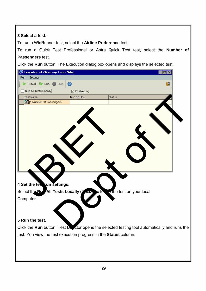
106
3 Select a test. To run a WinRunner test, select the Airline Preference test.
To run a Quick Test Professional or Astra Quick Test test, select the Number of Passengers test. Click the Run button. The Execution dialog box opens and displays the selected test.
4 Set the test run settings. Select the Run All Tests Locally check box to run the test on your local
Computer
5 Run the test. Click the Run button. Test Director opens the selected testing tool automatically and runs the
test. You view the test execution progress in the Status column.
JBIE
T
Dept o
f IT

107
6 Close the Execution dialog box. After the test run is complete, click Exit. 7 View a summary of test results in the Execution Grid. The Execution Grid displays the updated status for the test run. Results for each test step
appear in the Last Run Result pane.
JBIE
T
Dept o
f IT

108
8 View detailed test results from the Test Run Properties dialog box. In the Execution Grid, make sure your test is selected. Click the Test Run Properties button.
The Test Run Properties dialog box opens and displays the All Runs view.
JBIE
T
Dept o
f IT

109
9 View the test results in your selected testing tool. ➤ To view the test results in Quick Test Professional or Astra Quick Test, click the Launch Report button.
➤ To view the test results in WinRunner, click the View Report button.
10 View other test run information in the Test Run Properties dialog box. ➤ To view run details of the test, in the left menu, click Details.
➤ To view any attachments to a test, in the left menu, click Attachments.
➤ To view the parameters for a manual or WinRunner test, in the left menu, click
Configuration. Note that any changes that you make will be implemented in the next test
run.
➤ To view the on failure rules for an automated test, in the left menu, click Run Events. This
view also enables you to change your rules. Note that any changes that you make will be
implemented in the next test run.
➤ To view a list of changes made to the test run fields, in the left menu, click History.
11 Close the Test Run Properties dialog box. Click Exit. 12 Close your selected testing tool. In QuickTest Professional, Astra QuickTest, or WinRunner, chooses File > Exit.
JBIE
T
Dept o
f IT

110
Adding and Tracking Defects Locating and repairing defects is an essential phase in application development. Defects can
be detected and submitted by developers, testers, and end users in all stages of the testing
process. Using Test Director, you can submit defects detected in the application and track
them until they are repaired.
In this we will describe about:
➤ How to Track Defects
➤ Adding New Defects
➤ Matching Defects
➤ Updating Defects
➤ Mailing Defects
➤ Associating Defects with Tests
➤ Creating Favorite Views
How to Track Defects
When you submit a defect to a Test Director project, it is tracked through the following
stages: New, Open, Fixed, and Closed. A defect may also be Rejected or Reopened after it
is fixed.
When you initially report the defect to the Test Director project, it is assigned the status New,
by default. A quality assurance or project manager reviews the defect and determines
whether or not to consider the defect for repair. If the defect is refused, it is assigned the
status Rejected. If the defect is accepted, the quality assurance or project manager
determines a repair priority, changes its status to Open, and assigns it to a member of the
development team. A developer repairs the defect and assigns it the status Fixed. You retest
the application, making sure that the defect does not recur. If the defect recurs, the quality
assurance or project manager assigns it the status Reopened. If the defect is actually
repaired, the quality assurance or project manager assigns it the status Closed.
JBIE
T
Dept o
f IT

111
Adding New Defects You can add a new defect to a TestDirector project at any stage of the testing process. In the
following exercise you will submit the defect that was detected while running the Cruise Booking test.
To add a new defect: 1 Open the TestDirector_Demo project. If the TestDirector_Demo project is not already open, log on to the project.
2 Display the Defects module. Click the Defects tab. The Defects Grid displays defect data in a grid. Each row in the grid
displays a separate defect record.
3 Open the Add Defect dialog box. Click the Add Defect button. The Add Defect dialog box opens. Note that fields in red are
required.
JBIE
T
Dept o
f IT

112
4 Describe the defect. Type or select the following:
Summary: Unable to reserve a cruise from the Cruise page.
Category: Defect
Severity: 2-Medium
Subject: Cruises
Detected in Version: Version 1.01
Description: The defect was detected in the Cruise Booking test. When you click the Now
Accepting Reservations button, the Flight Finder page opens instead of the Cruise
Reservation page.
5 Attach the URL address for the Mercury Tours page where the defect was detected. Click the Attach URL button. The Attach URL dialog box opens.
JBIE
T
Dept o
f IT

113
Type the URL address of the Mercury Tours page:
http://<server name>/mtours/servlet/com.mercurytours.servlet.CruisesServlet
Click OK. Test Director displays the URL above the Description box.
6 Spell check your text. Place the cursor in the Description box and click the Check Spelling button.
If there are no errors, a confirmation message box opens. If errors are found, the Spelling
dialog box opens and displays the word together with replacement suggestions.
7 Add the defect to the Test Director project. Click the Submit button. Click OK to confirm.
8 Close the Add Defect dialog box. Click Close. Test Director adds the defect to the Defects Grid.
Matching Defects
Matching defects enables you to eliminate duplicate or similar defects in your project. Each
time you add a new defect, TestDirector stores lists of keywords from the Summary and
Description fields. When you search for similar defects, keywords in these fields are
matched against other defects.
Note that keywords are more than two characters and letter case does not affect your
results. TestDirector ignores the following: articles (a, an, the); coordinate conjunctions (and,
but, for, nor, or); boolean operators (and, or, not, if, or then); and wildcards (?, *, [ ]).
In the following exercise, you will match defects by comparing a selected defect with all other
existing defects in the TestDirector_Demo project.
To match defects: 1 Make sure that the Defects module is displayed. If the Defects module is not displayed, click the Defects tab.
2 Select Defect ID 37. In the Defects Grid, select Defect ID 37.
Note: If you cannot find Defect ID 37, click the Clear Filter/Sort button to clear the filter that
is applied to the grid.
JBIE
T
Dept o
f IT

114
3 Find similar defects. Click the Find Similar Defects button.
Test Director displays the results in the Similar Defects dialog box.
Test Director displays similar defects according to the percentage of detected similarity.
Click Close to close the Similar Defects dialog box.
Updating Defects Tracking the repair of defects in a project requires that you periodically update defects. You
can do so directly in the Defects Grid or in the Defect Details dialog box. Note that the ability
to update some defect fields depends on your permission settings.
In this exercise, you will update your defect information by assigning the defect to a member
of the development team, changing the severity of the defect, and adding a comment.
JBIE
T
Dept o
f IT

115
To update a defect: 1 Make sure that the Defects module is displayed. If the Defects module is not displayed, click the Defects tab.
2 Update the defect directly in the Defects Grid. In the Defects Grid, select the defect you added in “Adding New Defects”
To assign the defect to a member of the development team, in the Assigned to box in the
defect record, click the down arrow and select james_td from the list. 3 Open the Defect Details dialog box. Click the Defect Details button. The Defect Details dialog box opens.
4 Change the severity level of the defect. In the Severity box, select 5-Urgent.
JBIE
T
Dept o
f IT
116
5 Add a new R&D comment to explain the change in the severity level. Click Description in the left menu.
Click the Add Comment button. A new section is added to the Comments box, displaying
your user name and the current date. Type: This defect also occurs in Mercury Tours version 1.0.
6 View the Attachments. Click Attachments in the left menu. Note that the URL attachment is listed
7 View the History. Click History in the left menu to view the history of changes made to the defect. For each
changed field, TestDirector displays the date of the change, the name of the person who
made the change, and the new value.
8 Close the Defect Details dialog box. Click OK to exit the dialog box and save your changes.
Mailing Defects
You can send an e-mail about a defect to another user. This enables you to routinely inform
development and quality assurance personnel about defect repair activity. Test Director
includes a Go To Defect link in the e-mail which enables the recipient to go directly to the
defect.
In the following exercise, you will e-mail your defect to your mailbox.
To mail a defect: 1 Make sure that the Defects module is displayed. If the Defects module is not displayed, click the Defects tab.
2 Select a defect. Select the defect you added in “Adding New Defects”, and click the Mail Defects button. The
Send Mail dialog box opens.
JBIE
T
Dept o
f IT

117
3 Type a valid e-mail address. In the To box, type your e-mail address.
4 Include the attachments and history of the defect. In the Include box, select Attachments and History.
5 Add your comments. Under Additional comments, type: I will send you more information tomorrow.
6 E-mail the defect. Click Send. A message box opens. Click OK.
7 View the e-mail. Open your mailbox and view the defect you sent.
JBIE
T
Dept o
f IT

118
Associating Defects with Tests You can associate a test in your test plan with a specific defect in the Defects Grid. This is
useful, for example, when a new test is created specifically for a known defect. By creating
an association, you can determine if the test should be run based on the status of the defect.
Note that any requirements covered by the test are also associated with the defect.
You can also create an association during a manual test run. When you submit a defect, Test
Director automatically creates an association between the test run and the new defect.
In the following exercise, you will associate your defect with the Cruise Booking test in the
Test Plan module, and view the associated test in the Defects Grid.
Creating Favourite Views A favourite view is a view of a Test Director window with the settings you applied to it. For
example, in the Defects Grid, you may want to apply a filter to display only the defects that
were detected by you, are assigned to you, or have the status “Not Closed”.
JBIE
T
Dept o
f IT

119
AIM: study on the test management tool(eg winrunner)
Objective: Win Runner is a powerful automated testing tool for functional and regression testing.
BRIEF SUMMARY: Win Runner allows you to record GUI operations, while recording it automatically creates a
test script.
Test Script: An automated test program is called test script. Every test script consists of two types
of statements such as:
Navigational Statements to operate on build and check points to conduct testing.
Important Features of Win Runner: • Runs on Win Runner family operating system and different browser environments.
• Records the GUI operations in the record mode, automatically creates a test script
.This test can be modified if required and can be executed later in unattended mode.
• Can do functional/regression testing of application software written in programming
language such as Power Builder, VB,C/C++ and Java and can also carry out the
testing on ERP/CRM software packages.
• Checkpoints can be added to compare actual and expected results. Checkpoints can
be GUI checkpoints, bitmap and Web Links.
• Database checkpoints are used to verify data in a database during automated testing.
The records that are inserted, deleted, modified or updated will be highlighted so that
you can ensure database integrity and transaction accuracy.
• Virtual object wizard of Win Runner is used to teach Win Runner to recognize record.
JBIE
T
Dept o
f IT
120
Procedure: There are 6 steps in testing process:
1. GUI map file creation: By creating GUI map file the win runner can identify the GUI
objects in the application going to be created.
2. Test scripts creation: This process involves recording, programming or both. During
the process of recording tests, insert checkpoints when the responses of the
application need to be tested.
3. Debug The Test: Run the tests in debug mode to make sure whether they run
smoothly.
4. Run Tests: Run tests in verify mode to test the application.
5. View Results: This determines the success or failures of the test.
6. Report Defects: If a particular test run fails due to the defect in the application being
tested, defects can be directly reported through the test results window.
Two types of recording modes : • Context Sensitive Mode
• Analog Recording Mode
Context Sensitive Mode: Win runner captures and records the GUI objects, windows,
keyboards inputs and mouse click activities through context sensitive recording.
Analog Recording Mode: It captures and records the keywords inputs, mouse movement. It
does not capture the GUI object and windows. GUI map files the stored information, it learns
about the GUI objects and windows. A checkpoint enables you to check your application by
comparing its expected results of application to actual results.
By default Win Runner starts recording in context sensitive mode. If we want to
change it into analog mode we can follow below navigations.
Click Start recording twice or
Create Menu->record-analog or
F2 is the short key to change from one mode to another mode.
JBIE
T
Dept o
f IT

121
Exploring the WinRunner Window: Before you begin creating tests, you should familiarize yourself with the
Win Runner main window.
To start WinRunner:
Choose Programs > WinRunner > WinRunner on the Start menu.
The first time you start WinRunner, the Welcome to WinRunner window opens.
From the welcome window you can create a new test, open an existing test, or
View an overview of WinRunner in your default browser.
The first time you select one of these options, the WinRunner main screen opens
With the “What’s New in WinRunner” section of the help file on top. If you do not
Want the welcome window to appear the next time you start WinRunner, clear the show on
start-up check box.
Each test you create or run is displayed by WinRunner in a test window. You can open
many tests at one time.
JBIE
T
Dept o
f IT

122
.
1. The Win Runner window displays all open tests.
2. Each test appears in its own test window. You use this window to record, program, and edit test scripts.
3. Buttons on the Standard toolbar help you quickly open, run, and save tests.
4. The User toolbar (right side) provides easy access to test creation tools.
5. The status bar (Run Name) displays information about selected commands and the
current.
The Standard toolbar provides easy access to frequently performed tasks, such as
opening, executing, and saving tests, and viewing test results.
1. New Test 2. Open 3. Save 4. Run mode 5. Context sensitive mode 6. Run from top
JBIE
T
Dept o
f IT

123
7. Stop 8. Pause 9. Step 10. Step into 11. Toggle breakpoint 12. Break in function 13. Add watch 14. Test results 15. Help
The User toolbar displays the tools you frequently use to create test scripts. By default, the
User toolbar is hidden.
To display the User toolbar choose Window > User Toolbar. When you create Tests, you
can minimize the WinRunner window and work exclusively from the Toolbar.
1. Record - Context Sensitive 2. Stop 3. GUI Checkpoint for Single Property 4. GUI Checkpoint for Object/Window 5. GUI Checkpoint for Multiple Objects 6. Bitmap Checkpoint for Object/Window 7. Bitmap Checkpoint for Screen Area 8. Default Database Checkpoint 9. Custom Database Checkpoint 10. Synchronization Point for Object/Window Property 11. Synchronization Point for Object/Window Bitmap 12. Synchronization Point for Screen Area Bitmap 13. Edit GUI Checklist 14. Edit Database Checklist 15. Get Text from Object/Window 16. Get Text from Screen Area 17. Insert Function from object window 18. Insert Function from Function generator
The User toolbar is customizable. You choose to add or remove buttons using the Settings > Customize User Toolbar menu option. When you re-open Win Runner, the User toolbar
appears as it was when you last closed it.
Note that you can also execute many commands using soft keys. Soft keys are Key board
shortcuts for carrying out menu commands. You can configure the Soft key combinations for
your keyboard using the Soft key Configuration utility in Your WinRunner program group. For
more information, see the “WinRunner at a Glance” chapter in your WinRunner User’s Guide.
JBIE
T
Dept o
f IT

124
How Does Win Runner Identify GUI Objects? GUI applications are made up of GUI objects such as windows, buttons, lists, and Menus. When Win Runner learns the description of a GUI object, it looks at the object’s Physical
properties. Each GUI object has many physical properties such as “Class,” “label,” “width,” “height”, “handle,” and “enabled” to name a few. Win Runner, however, only
learns the properties that uniquely distinguish an Object from all other objects in the
application. For more information regarding Properties, refer to the “Configuring the GUI
Map” chapter in the WinRunner User’s Guide.
Choosing a GUI Map Mode:
Before you start teaching Win Runner the GUI of an application, you should
Consider whether you want to organize your GUI map files in the GUI Map File per Test
mode or the Global GUI Map File mode.
The GUI Map File per Test Mode: In the GUI Map File per Test mode, Win Runner automatically creates a new GUI map file
for every new test you create. WinRunner automatically saves and opens the GUI map file
that corresponds to your test. If you are new to WinRunner or to testing, you may want to consider working in the GUI Map
File per Test mode. In this mode, a GUI map file is created automatically every time you
create a new test. The GUI map file that corresponds to your test is automatically saved
whenever you save your test and automatically loaded whenever you open your test. This is
the simplest mode for inexperienced testers and for ensuring that updated GUI Map files are
saved and loaded.
The Global GUI Map File Mode:
In the Global GUI Map File mode, you can use a single GUI map for a group of tests.
When you work in the Global GUI Map File mode, you need to save the information that
WinRunner learns about the properties into a GUI map file. When you run a test, you must
load the appropriate GUI map file. If you are familiar with WinRunner or with testing, it is
JBIE
T
Dept o
f IT

125
probably most efficient to work in the Global GUI Map File mode.
By default, WinRunner is set to the Global GUI Map File mode.
To change the mode to the GUI Map File per Test mode
choose Settings > General Options, click the Environment tab, and select GUI Map File per Test. Click OK to close the dialog
box.
Note: 1)If you change the GUI Map File mode, you must restart WinRunner for the changes
to take effect.
2)If you choose to work in the Global GUI Map File mode, proceed to the section below on Using the Rapid Test Script Wizard.
Using the Rapid Test Script Wizard
If you choose the Global GUI Map File mode, the Rapid Test Script wizard is usually the
easiest and quickest way to start the testing process.
Note: The Rapid Test Script Wizard is not available when you work in GUI Map File per Test mode. The Rapid Test Script Wizard systematically opens the windows in your application and
learns the description of every GUI object. The wizard stores this information in a GUI map
file. To observe Win Runner’s learning process, use the Rapid Test Script Wizard on the Flight Reservation application. Note: The Rapid Test Script Wizard is not available when the Terminal Emulator, the Web Test or the Java add-in is loaded. Therefore, if you are using one or
more of these add-ins, skip the remaining sections of this lesson.
JBIE
T
Dept o
f IT

126
EXAMPLE:
FLIGHT RESERVATION APPLICATION:
1. Log in to the Flight Reservation application. If the Login window is open, type your name in the Agent Name field and mercury in
the Password field and click OK. The name you type must be at least four characters long.
If the Login window is not already open on your desktop,
choose Programs > WinRunner > Sample Applications > Flight 1A on the Start menu
and then log in, as described in the previous paragraph. 2. Start Win Runner. If Win Runner is not already open, choose Programs > WinRunner > Win Runner on the Start menu. 3. Open a new test. If the Welcome window is open, click the New Test button. Otherwise, choose
File > New. A new test window opens in WinRunner
4. Start the Rapid Test Script wizard. Choose Create > Rapid Test Script Wizard. Click Next in the wizard’s Welcome
Screen to advance to the next screen.
JBIE
T
Dept o
f IT
127
6. Point to the application you want to test. Click the hand button and then click anywhere in the Flight Reservation application. The
application’s window name appears in the wizard’s Window
Name box. Click Next
6 .Make sure that all the check boxes are cleared. For the purposes of this exercise, confirm that all the check boxes are cleared.
You will use the wizard only to learn the GUI of the Flight Reservation application. Click Next.
Note: A regression test is performed when the tester wishes to see the progress of the
testing process by performing identical tests before and after a bug has been fixed. A
regression test allows the tester to compare expected test results with the actual results.
7. Accept the default navigation controls. Navigation controls tell WinRunner which GUI objects are used to open windows. The Flight
Reservation application uses the default navigation controls (... and > >) so you do not need
to define additional controls. Click Next.
8. Set the learning flow to “Express.” The learning flow determines how WinRunner walks through your application.
Two modes are available: Express and Comprehensive. Comprehensive mode lets you
customize how the wizard learns GUI object descriptions. First-time WinRunner users should
use Express mode. Click the Learn button. The wizard begins walking through the
application, pulling down menus, opening windows, and learning object descriptions. This
process takes a few minutes. If a pop-up message notifies you that an interface element is
disabled, click the Continue button in the message box. If the wizard cannot close a window,
it will ask you to show it how to close the window. Follow the directions on the screen.
9. Accept “No” in the Start Application screen. You can choose to have WinRunner automatically open the Flight Reservation application
each time you start WinRunner. Accept the default “No.” Click Next.
10. Save the GUI information and a start up script. The wizard saves the GUI information in a GUI map file. The wizard also creates a start up
script. This script runs automatically each time you start WinRunner. It contains a command
which loads the GUI map file so that WinRunner will be ready to test your application. Accept
the default paths and file names or define different ones. Make sure that you have write
permission for the selected folders. Click Next.
JBIE
T
Dept o
f IT

128
11. Click OK in the Congratulations screen. The information WinRunner learned about the application is stored in a GUI map file.
Running the Test: You are now ready to run your recorded test script and to analyze the test results.
WinRunner provides three modes for running tests. You select a mode from the
toolbar.
Use Verify mode when running a test to check the behavior of your application, and when
you want to save the test results.
Use Debug mode when you want to check that the test script runs smoothly without errors
in syntax.
Use Update mode when you want to create new expected results for a GUI checkpoint or
bitmap checkpoint.
To Run the test: 1 Check that WinRunner and the main window of the Flight Reservation application are open on your desktop. JB
IET
Dept o
f IT

129
2 Make sure that the lesson3 test window is active in WinRunner. Click the title bar of the lesson3 test window. If the test is not already open,
choose File > Open and select the test.
3 Make sure the main window of the Flight Reservation application is active. If any dialog boxes are open, close them.
4 Make sure that Verify mode is selected in the toolbar. 5 Choose Run from Top. Choose Run > Run from Top or click the Run from Top button. The Run Test dialog box opens
JBIE
T
Dept o
f IT

130
6 Choose a Test Run name. Define the name of the folder in which WinRunner will store the results of the test. Accept the
default folder name “res1.” The results folder will be stored within the test’s folder.
Note the Display Test Results at end of run check box at the bottom of the dialog box.
When this check box is selected, WinRunner automatically displays the test results when the
test run is completed. Make sure that this check box is selected.
7 Run the test. Click OK in the Run Test dialog box. WinRunner immediately begins running the test.
Watch how WinRunner opens each window in the Flight Reservation application.
8 Review the test results. When the test run is completed, the test results automatically appear in the WinRunner Test
Results window. See the next section to learn how to analyze the test results.
Analyzing Test Results: Once a test run is completed, you can immediately review the test results in the WinRunner Test Results window. WinRunner color-codes results (green indicates passed and red
indicates failed) so that you can quickly draw conclusions about the success or failure of the
test.
1 Make sure that the WinRunner Test Results window is open and displays the test results. If the WinRunner Test Results window is not currently open, first click the test window to
activate it, and then choose Tools > Test Results or click the Test Results button.
JBIE
T
Dept o
f IT

131
1. Displays the name of the current test.
2. Shows the current results directory name.
3. Shows whether a test run passed or failed.
4. Includes general information about the test run such as date, operator name, and total
run time. To view these details, double click the Information icon.
5. The test log section lists the major events that occurred during the test run. It also lists
the test script line at which each event occurred
2 Review the results. 3 Close the Test Results window. Choose File > Exit in the WinRunner Test Results window.
4 Close the test. Choose File > Close.
5 Close the Flight Reservation application. Choose File > Exit.
JBIE
T
Dept o
f IT

132
JBIE
T
Dept o
f IT