iv. nps autonomous underwater vehicle a....
TRANSCRIPT

IV. NPS AUTONOMOUS UNDERWATER VEHICLE
A. INTRODUCTION
Detailed knowledge regarding robot requirements is a necessary prerequisite for
implementing robot operation in a virtual world. This chapter describes key
considerations in underwater robotics hardware and software, particularly as
instantiated in the NPS AUV. Familiarity with the Chapter II review of related
robotics projects is recommended. An overview of generic AUV hardware and
software is followed by NPS AUV hardware specifications and software
characteristics. Additional overview descriptions of the NPS AUV and related
research appear in (Brutzman, Compton 91) and (Healey 92a). Due to the large
variety of critical tasks an autonomous underwater robot must perform, a robust
multilevel software architecture is essential. The software architecture used by the
NPS AUV is the Rational Behavior Model (RBM). The three levels of RBM are
described with emphasis on the real-time characteristics of each level. Details are also
provided regarding vehicle software developed in this work. Specific contributions of
this dissertation include extending the RBM execution level and improving
implemented RBM interprocess communication (IPC).
B. UNDERWATER ROBOTICS
Although there are far fewer robots designed to operate underwater than in other
environments, there is much diversity in the hardware and software of those robots
that exist. Underwater robot hardware is mostly concerned with watertight integrity,
maneuvering and sensing. Underwater robot software is usually preoccupied with
real-time hardware control. Implemented higher-level functions are rarely as
sophisticated or capable as desired. Although manipulators and intervention tools are
common on remotely-operated vehicles (ROVs), they remain a rarity on autonomous
robots because fundamental problems of ship control, navigation and classification of
55
detected objects are not well solved. Recent overviews of prominent AUVs and
related technical problems are (Fricke 94) (Zorpette 94). The best way to understand
the capabilities and weaknesses of these vehicles is to watch them in operation. High
quality videotape footage and written summaries of state-of-the-art underwater robots
appear in recent video conference proceedings (Brutzman 93a) (Brutzman 94a).
1. Underwater Vehicle Hardware
Unfortunately the cost in time and money of assembling an AUV is high
and currently beyond the reach of most academic institutions. Nevertheless most
hardware components are commercially available, particularly since the remote
operated vehicle (ROV) industry is well established and thousands of ROVs have been
deployed. Institutions considering building an AUV are advised to start by looking at
existing ROVs and related components that can be adapted for autonomous operation.
Pressure hulls for AUVs typically fall into two categories: streamlined and
open frame. Streamlined hulls are useful for operating at high speed, or minimizing
drag so that propulsion endurance is maximized. Open frame hulls typically consist of
a framework of piping open to the ocean, with all components bolted onto the frame
wherever appropriate. At low operating speeds drag is not a significant handicap, and
the open frame simplifies placement and adjustment of hardware devices.
Power supplies and propulsion endurance are a significant weak point in
current AUVs. Most vehicles are powered by lead-acid or silver-zinc batteries with
usable capacity ranging from several hours to about a day. Hydrogen gas generation
during battery charging or discharge is a serious personnel and equipment hazard.
Research and development work in improving power density has focused for a number
of years on alternative battery electrochemistries, closed-cycle (self-oxidizing) engines
and aluminum hydroxide fuel cells, but dramatic improvements in cost or capability
are not soon expected. Eventually the active research and development of improved
battery technology for electric cars and laptop computers may provide useful power
supply alternatives.
56

Sensors are one of several key technologies that distinguish underwater
robots from ground, air and space-based robots. Since the oceans are generally
opaque to visible light at moderate-to-long ranges, vision-based video systems are
unreliable in turbid water and are ordinarily of use only at short distances. Vision
systems usually require intense light sources which further deplete precious energy
reserves. In comparison to underwater computer vision, sonar (acoustic detection) has
long been a preferred sensing method due to the very long propagation ranges of
sound waves underwater. However, sound waves can be bent by variations in depth,
temperature and salinity. A variety of problems including ambient noise, multipath
arrival, fading, shadow layers, masking and other effects can make sonar use difficult.
Since active sonar typically provides good range values with approximate bearing
values, algorithms for sonar recognition are much different than vision algorithms.
Blue-green lasers are relatively new underwater sensors that are useful since they can
provide accurate range and accurate bearing data at short-to-moderate ranges with low
power consumption. Other hardware sensors of interest to AUVs include pressure
instruments, flow detectors, inertial navigation acceleration and angular rate sensors,
and fast Global Positioning System (GPS) receivers. New and varied sensors are
being developed for oceanographic survey measurements and trace chemical detection
(Bales 94a, 94b).
Communications with underwater vehicles are notoriously difficult.
Tethers can provide high bandwidth and even a power supply, but remain subject to
entanglement and breakage with the subsequent possibility of vehicle loss. Tethers
typically require tether management systems which can be very costly in their own
right. Tethers also induce undesirable and varying drag forces on the underwater
vehicle. Acoustic modems are a useful innovation that can provide communications
links, but are very susceptible to channel noise and channel loss problems. A serious
limitation in current acoustic modems is incompatibility with the Internet Protocol
(IP), and further network research efforts are necessary to incorporate forward error
correction (FEC) and transport protocol functionality for reliable internetworking of
57

underwater devices. Acoustic long-baseline and short-baseline navigation can be used
to determine underwater vehicle location by measuring time of flight of pings between
beacons at fixed locations and a transponder located on the vehicle. Beacon pings can
be further encoded to pass positional information back to the vehicle. Unfortunately,
the primary limitation of navigation in an acoustic field is that beacons must be
deployed beforehand in known locations around the area of interest.
2. Robot Software Architectures
Designing an AUV is complex. Many capabilities are required for an
underwater mobile robot to act capably and independently. Stable physical control,
motion control, sensing, motion planning, mission planning, replanning and failure
recovery are example software components that must be solved individually for
tractability. The diversity and dissimilarity of these many component subproblems
precludes use of a single monolithic artificial intelligence (AI) paradigm.
Distributed AI usually addresses specifications and protocols between
similar autonomous agents working cooperatively on global problems. Hybrid
reasoning often refers to novel combinations of two or three techniques to improve
overall performance when solving a single problem type. Neither definition appears
suitable for general robot control. Multiple dissimilar AI processes must interact in an
intelligent manner to achieve the robust capabilities and multiple behaviors needed by
a mobile robot (Elfes 86). A variety of robot architectures have been proposed and
developed to provide the control framework under which multiple AI processes can
interact. A brief discussion of current robot architectures is therefore useful to clarify
the scope of robot design issues.
Robot architectures can be classified over a spectrum that ranges from
hierarchical to reactive (Byrnes 93). Hierarchical architectures can be characterized as
being deliberative, symbolic, structured, "top down," goal-driven, and having explicit
focus of attention. They are often implemented using backward inferencing.
Hierarchical approaches typically contain world models and use planning and search
techniques to achieve strictly defined goals. Hierarchical architectures tend to be
58

somewhat rigid, unresponsive in unpredicted situations and computation-intensive.
Nevertheless they remain capable of highly sophisticated performance.
Reactive architectures are subsumptive, "bottom up," sensor-driven, layered
and may often be characterized by forward inferencing. Reactive architectures attempt
to combine robust subsuming behaviors while avoiding dynamic planning and world
models. Reactive architectures appear to behave somewhat randomly and achieve
success without massive computations by using well-considered behaviors that tend to
lead to task completion (Brooks 86, 90). Scaling up to complex missions is difficult.
Stability and deterministic performance is elusive.
It is interesting to note that numerous robot architecture researchers have
recently proposed hybrid control architectures (Kwak 92) (Bonasso 92)
(Bellingham 90) (Payton 91) (Spector 91). A common theme in these proposals is
integrating the long-term deliberation, planning and state information found in
hierarchical approaches with the quick reaction and adaptability of subsumptive
behaviors. Individual weaknesses of hierarchical and reactive architectures appear to
be well-balanced by their respective strengths.
Physical stability and reliability deserve repeated mention in the context of
multiple interacting processes. Control system considerations are often overlooked
under the guise of simplifying assumptions that hide important real world restrictions
and pitfalls. Robot survivability dictates that physical and logical behavior must
always converge to a stable yet adaptive set of states. Divergence, deadlock, infinite
loops and unstable dynamic behavior must be detectable and preventable. Hard
real-time operating constraints on sensing, processing, action and reaction must be
similarly resolved. Robotics research in other environments are expected to be
pertinent and useful; for example, physical stability prerequisites become similarly
important for ground robots as they progress from structured to unrestricted
environments. Finally it is worth reiterating that an underwater virtual world is
proposed as the best way to enable repeated testing of underwater vehicle control,
stability and reliability.
59

C. NPS AUV HARDWARE
The NPS AUV has four paired plane surfaces (eight fins total) and bidirectional
twin propellers. The hull is made of pressed and welded aluminum. The vehicle is
ballasted to be neutrally buoyant at 387 lb. Design depth is 20 ft (6.1 m). A pair of
sealed lead-acid gel batteries supports vehicle endurance of 90-120 minutes at speeds
up to 2 ft/sec (0.61 m/sec).
A free-flooded fiberglass sonar dome supports two forward-looking sonar
transducers, a downward-looking sonar altimeter, a water speed flow meter and a
depth pressure cell. Five rotational gyros mounted internally are used to measure
angles and rates for roll, pitch and yaw respectively. Cross-body thruster tunnels were
designed and built for the NPS AUV. An inline bidirectional propeller in each
thruster can provide up to 2 pounds of force (Cody 92) (Healey 94b).
Detailed specifications of all NPS AUV hardware components are presented in
(Torsiello 94). An external view of the vehicle is shown in Figure 4.1 and primary
internal component arrangements are shown Figure 4.2. A detailed schematic of
vehicle internal components appears in Figure 4.3. A photograph showing the
NPS AUV in the test tank is provided in Figure 4.4.
60

Figure 4.1. Exterior view of NPS AUV, 8 plane surfaces and twin propellers.Length is 8’ (2.4 m), height 10" (25.4 cm), width 16.5" (41.9 cm).Weight and buoyancy are each 435 lb (197.5 kg) when submerged.
Figure 4.2. Internal view of principal NPS AUV components.Four cross-body thrusters: two lateral and two vertical.Two card cages contain 68030/OS-9 and 386/DOS microprocessors.
61

Figure 4.3. NPS AUV II internal components layout (Torsiello 94).
Figure 4.4. NPS AUV shown in test tank (Torsiello 94).
62

The NPS AUV is primarily designed for research on autonomous dynamic
control, sensing and AI. Software control of the vehicle is provided at a high level
corresponding to strategic planning and tactical coordination, as well as at a low level
corresponding to hydrodynamics control of plane surfaces and propellers. Sensors are
also controlled via execution level microprocessor-hardware interfaces, although some
sensor functions (such as steering individual sonar transducer bearing motors) may be
optionally commanded by the supervising tactical level. TRITECH sonar range
resolution varies with maximum range and selected range bin size. Sonar
specifications appear in Table 4.1, derived from (Torsiello 94).
Table 4.1. NPS AUV Sonar Types and Specifications.
Sonars andparameters
Tritech ST-1000 Tritech ST-725 DatasonicsPSA-900
Function Conical scan Vertical sector scan Depth sensing
Beam shape 1° pencil cone 24° verticalby 1° wide
10° cone
Frequency 1250 KHz 725 KHz 210 KHz
Maximum range 4..50 m 6..100 m 27 m
Range resolution 1..80 cm 4..80 cm ~ 1 cm
Steering increment 0.9° horizontalmechanical drive
0.9° horizontalmechanical drive
fixed downwardnot steerable
Operating modes Sector Profile,Sector Scan
Sector Scan Data averaging(4 ping window)
Ping rate 10 Hz 10 Hz 10 Hz
Location in bow port below port above starboard below
Two microprocessors are available for use aboard the NPS AUV:
a Motorola 68030 and an Intel 30386. Each is mounted on a 4" by 6" Eurobus card
manufactured by Gespac Inc. The operating system for the 68030 is the OS-9
63
real-time operating system by Microware Inc. Support for the OS-9 operating system
running on Gespac computers is problematic at best; a recommended reference for
OS-9 users is (Dayan 92). Operating system for the 30386 is Digital
Research (DR) DOS 6.0, chosen for small kernel size and the ability to manually
switch between tasks. Multitasking operating systems such as Windows and OS/2
were earlier considered and rejected due to their insistence on graphical user interface
overhead. To date the 30386 has not been used for in-water missions. A variety of
different processors and operating systems are being considered for future NPS AUV
configurations. Unfortunately the large volume of intricate legacy code dedicated to
controlling numerous analog-digital controller cards and devices has so far precluded
wholesale replacement of the current microprocessor/operating system combinations.
Vehicle designers must note that sealed lead-acid gel batteries are still
susceptible to hydrogen gas generation and venting (Calder 94), which becomes an
explosive hazard above 5% by atmospheric volume. Reliance on NPS AUV battery
seals together with excessive recharging, mission repetition and insufficient venting
resulted in a submerged hydrogen explosion in early 1994. Significant hull damage
resulted and most electrical equipment was a complete loss due to flooding under
power. No personnel were injured. Repairs took most of the year, but the refurbished
and renamed NPS AUV "Phoenix" resumed submerged testing in October 1994.
D. NPS AUV SOFTWARE
Ongoing development of NPS AUV software has continued for over eight years.
A great deal of novel software research has been conducted during this period.
Underwater robot software architectures are a particular challenge because they include
a great many of the hardest problems in robotics and AI over short, medium and long
time scales. The principal features and lessons learned to date relating to NPS AUV
software are summarized in the following sections.
64
1. Rational Behavior Model (RBM) Software Architecture
The Rational Behavior Model (RBM) is a trilevel multiparadigm software
architecture for the control of autonomous vehicles (Kwak 92) (Byrnes 92, 93, 95).
Strategic, tactical and execution levels correspond roughly to high-level planning,
intermediate computational processing of symbolic goals, and direct interaction with
vehicle hardware and the environment. The three levels of RBM correspond to levels
of software abstraction which best match the functionality of associated tasks.
Temporal requirements range from soft real-time planning at the strategic level to hard
real-time requirements at the execution level, where precise control of vehicle sensors
and propulsion is necessary to prevent mission failure and vehicle damage.
RBM provides an overall structure for the large variety of NPS AUV
software components. A particular advantage of RBM is that the three levels are
analogous to the watchstanding organization of naval ships. The strategic level
matches long-range planning by the commanding officer. The tactical level
corresponds to officer of the deck, navigator and officer watchstanders. The execution
level corresponds to helmsmen, planesmen and sonar operators. Such analogies are
particularly useful for naval officers working on this project who know how to drive
ships, since it provides a well-understood partitioning of duties and a precisely defined
task lexicon.
Programming paradigms are explicitly defined at each level of RBM in
order to best match programming languages to objectives. Strategic level goals are
typically defined and met using backwards chaining. Tactical modules are
object-oriented and use message passing to communicate. The execution level is
imperative. Typical languages for each level areProlog, object-orientedClassic Ada
andC, respectively. Variations on the strategic level have produced provably
equivalent variations using forward chaining and backward chaining (Scholz 93).
(Byrnes 93) implemented all three RBM levels concurrently in simulation, running
under networked Unix workstations but not on the NPS AUV proper. Initial
implementation efforts for this dissertation included integrating and testing a tactical
65
level with an improved execution level, where source code for both levels compiles
identically and runs compatibly either on vehicle hardware or on networked
workstations.
The primary contribution of this dissertation to RBM is extensive
development and implementation of the execution level (Brutzman 94e), as well as
formal specification and implementation of execution level communications
requirements. As predicted by (Brutzman 92a, 92c), availability of hydrodynamics and
sonar models for integrated simulation during robot development have been invaluable
for development of robot control algorithms. Implementations of strategic and tactical
levels in previous theses have only run in isolation and have never been tested
underwater due to inadequate execution level functionality (Brutzman 92a) (Byrnes 93)
(Compton 92) (Ong 90) (Scholz 93) (Thornton 93) (Wilkinson 92). Completion of a
robust execution level in this dissertation now permits meaningful integration of
strategic and tactical RBM levels with a capable execution level.
2. Multiple Operating Systems and Multiple Programming Languages
Given the relative uniqueness and slowness of the NPS AUV
microprocessors, operating systems and interfaces, it is desirable to be able to compile,
run and test AUV software on a variety of platforms. The predominant computing
asset available to the NPS AUV research group is Unix workstations, particularly
Silicon Graphics Inc. (SGI) graphics workstations. Although Unix is not a real-time
operating system, it can be made to emulate the functionality of the real-time
operating system OS-9 used for the execution level, and the more common DOS
operating system used for the tactical level. To date the strategic level has not been
implemented in the vehicle due to lack of a workable multitasking environment on the
tactical 80386 microprocessor. Several attempts to multitask strategic and tactical
levels using theAda and/orCLIPS languages were unsuccessful (Scholz 93)
(Thornton 93).
The area of greatest interest to robotics researchers is developing source
code that implements proposed algorithms. Standardized languages are an essential
66

requirement for source code that is portable across multiple hardware platforms.
Languages used in the NPS AUV project reflect this criteria:Prolog, CLIPS, Ada,
Classic Ada, C andC++ have all been used. Theoretically, compilers for different
architectures will compile source code identically on each platform. In practice,
successful compilation of a single version of source code by multiple compilers is a
rarity. Modified compilation controlmakefilesand context-sensitive compiler
directives may be able overcome variant compiler limitations (Brutzman 94e). Such
an approach is essential because there then needs to be only one single version of
robot code that can compile and run successfully in any appropriate environment.
NPS AUV project experience has repeatedly shown that failure to insist on
cross-platform compatibility leads to "versionitis" and configuration control problems
which prevent research code from being successfully implemented and integrated with
previous vehicle software efforts. Such failures are unacceptable.
Given that source code is written in a standardized language and compiles
on all pertinent platforms, a further significant problem can occur. Although the
hybrid language approach espoused by RBM provides an excellent match between
software abstraction and intended functionality, getting dissimilar languages to
compile, link and execute compatibly is extremely difficult. In every possible
combination that we have examined and tested, implementation of hooks between
languages and linking multiple language object files were not standardized.
Furthermore external language hooks typically do not perform as advertised. Despite
Herculean efforts, several RBM-related research efforts have failed to get different
levels of RBM communicating properly due to this vulnerability.
Fortunately, we have encountered one widely available IPC technique that
is likely to support any choice of programming language, operating system or
hardware architecture: use of standard Berkeley Standard Distribution (BSD) sockets
compatible with the Internet Protocol (IP) (Stevens 90). IP-compatible socket
communications are implemented on all computer platforms, and are available as
auxiliary function libraries in most programming languages of interest. Use of sockets
67

has several added benefits: processes can run independently, interchangeably and
remotely on vehicle processors or networked workstations. Current NPS AUV
implementation efforts call for replacing the hard-wired and hard-coded serial and
parallel port communications between processors with a network interface for each
vehicle microprocessor. Building a small network internal to the vehicle eliminates
specialized hardware and software communications, and does not impose a noticeable
performance penalty. It also permits connecting vehicle processors and processes to
any remote entity on the Internet. Even tethers between an unmanned underwater
vehicle (UUV) and the surface can be Ethernet connections (Bellingham 94). The
strength and numerous benefits of this approach have led us to network all possible
components of AUV-related software, both internal and external.
3. Execution Level Software
The executionprogram is a new and extended implementation of the RBM
execution level for the NPS AUV (Brutzman 94e). Originally based on the work of
(Marco 95) and others,executionnow includes a command language and runs
identically on the laboratory AUV hardware or on a networked SGI workstation.
Real-time performance for a 10 Hz control cycle was maintained in each environment.
Code development on workstations enables faster compilation and provides more
robust debugging tools which are nontrivial benefits for such a large program.
Principal components of theexecutionprogram include invocation and stored mission
script file commands, communications to the tactical level, communications to the
virtual world, vehicle hardware interfaces, maneuvering control algorithms,
standardized telemetry data recording, and supplemental mathematical functions to
support computational geometry calculations. These supplemental functions include
normalize (angle)which normalizes an angle to the range [0..π), normalize2 (angle)
which normalizes an angle to the range (-π/2..π/2], andatan2 (y, x)which returns the
angle to a point in the proper quadrant.
Vehicle control algorithms are implemented using either thrusters (hovering
modes), planes/rudders/propellers (cruise modes) or all in combination. Control
68

algorithms for the following behaviors are included: depth control, heading control,
open-loop rotation, open-loop lateral motion, waypoint following and hovering.
Control algorithms are permitted to operate both thrusters and planes/rudders/propellers
simultaneously when such operation does not mutually interfere. All control code has
been developed and tested in conjunction with the construction of the hydrodynamics
model presented in Chapter VI. Design, tuning and optimization of control algorithms
in isolation and in concert is the subject of active research (Cristi 89) (Yoerger 85, 90)
(Papoulias 89, 91) (Healey 89, 92b, 93) (Fossen 94) (Marco 95) and remains an
important area for future work. Control algorithm robustness is a particularly
important topic since potentially fatal nonlinear instabilities are possible and vehicle
reliability is paramount. Individual control algorithms created as part of this
dissertation follow.
Rudder steering control equations:
(4.1)
Planes depth control equations:
(4.2)
Note that planes and rudder are each constrained≤ ± 40° to prevent excessive
deflection and subsequent reduction of control above ± 45°. Planes and rudders are
zeroed at very low forward speeds in order to eliminate synchro hunting and
chattering.
69

Vertical thruster depth control equations:
(4.3)
Lateral thruster heading control equations:
(4.4)
Waypoint hovering mode control equations:
(4.5)
(4.6)
(4.7)
(4.8)
(4.9)
70

(4.10)
(4.11)
(4.12)
Associatedk coefficients are all positive and appear in Figure 4.5.
4. Communications Among AUV Processes and the Virtual World
Since RBM is a multilevel architecture, communications between levels
must be formally defined. Communications between robot and virtual world must also
be clearly specified. Defining communications includes establishing a physical path
for data transfer as well as defining the syntax and protocol of exchanged messages.
Design objectives include reliability and clarity so that messages are easily created and
easily understood, either by software processes or by people.
71

Two kinds of messages are defined for use by robot and virtual world.
Figure 4.5. Control algorithm coefficients frommission.output.constantsfile.
__________________________________________________
AUV execution level control algorithm coefficients__________________________________________________
k_psi k_r k_v k_z k_w k_theta k_q
1.00 2.00 0.00 15.00 2.00 4.00 1.00
k_thruster_psi k_thruster_r k_thruster_rotate
0.60 5.00 2.25
k_thruster_z k_thruster_w
10.00 80.00
k_propeller_hover k_surge_hover
200.00 6000.00
k_thruster_hover k_sway_hover
4.00 40.00
The first is the telemetry vector, which is a list of all vehicle state variables pertinent
to hydrodynamic and sensor control. Telemetry vectors are passed as a string type.
The second kind of messages allowed are free-format commands. Free-format
command messages are also string types, starting with a predefined keyword and
followed by entries which may optionally have significance depending on the initial
keyword. Messages with unrecognized keywords are treated as comments. These two
kinds of messages (telemetry and commands) can be used for any communication
necessary among robot-related entities. Employment of string types facilitates transfer
72

between different architectures, transfer via sockets, and file storage. String types also
ensure that all communications are readable by both robot and human, a trait that is
particularly useful during debugging. An open format for command messages permits
any user or new application to communicate with little difficulty.
Within the AUV, the basic communications flow between execution level
and tactical level is straightforward. All telemetry vectors are sent from the execution
level to the tactical level, providing a steady stream of time-sensitive, rapidly updated
information. The tactical level may send commands to the execution level as desired,
and the execution level may return informational messages between telemetry vectors
as appropriate. Nonadaptive tactical level functionality can also be provided by
prescripted mission command files. Telemetry vector records and command messages
are logged in separate mission output files for post-mission analysis and replay. Each
of these communications message types has been implemented and tested satisfactorily
(Brutzman 94e). Communication protocols between tactical level and strategic level
are presented in (Byrnes 93) and are not examined here.
73

Specific elements of the telemetry record appear in Figure 4.5 below.
Both data communications internal to the vehicle (execution and tactical levels) and
data communications external to the vehicle (execution level and virtual world) utilize
the telemetry vector and keyword command message conventions. Currently the data
path between execution and tactical levels consists of paired simplex text streams over
serial and parallel connections between the two microprocessors. The data path
between the execution level and the virtual world is via an Ethernet socket. In the
future, serial and parallel port data paths between the execution and tactical processors
are expected to be replaced by Ethernet sockets. Figure 4.7 shows physical data paths
and information flow both internal and external to the vehicle.
Figure 4.6. Telemetry vector elements.
time
x y z phi theta psi
u v w p q r
x_dot y_dot z_dot phi_dot theta_dot psi_dot
delta_rudder delta_planes
propeller_port_rpm propeller_stbd_rpm
thrusters_bow_vertical thrusters_stern_vertical
thrusters_bow_lateral thrusters_stern_lateral
ST1000_range ST1000_bearing ST1000_strength
ST725_range ST725_bearing ST725_strength
74

Figure 4.7. NPS AUV hardware configuration and internal interprocess communication (IPC).
75

The telemetry vector serves several essential purposes. In addition to
providing a steady stream of information from the execution level to the tactical level,
the telemetry vector also serves as the data transfer mechanism between execution
level and virtual world. Efficient communications between robot and virtual world are
essential if rapid real-time 10 Hz robot response is to be maintained. The telemetry
record is a concise and complete way to support all of these data communications
requirements.
Robot execution software is designed to operate both in the virtual world
and in the real world. While sensing in the virtual world, distributed hydrodynamics
and sonar models fill in pertinent telemetry vector slots. While sensing in the real
world, actual sensors and their corresponding interfaces fill in pertinent telemetry
vector slots. In either case, the remainder of the robot execution program which deals
with tactical communications, command parsing, dynamic control, sensor interpretation
etc. is unaffected. While operating in the virtual world, robot propulsion and sensor
commands are communicated via the same telemetry vector. While operating in the
real world, robot propulsion and sensor commands are sent directly to hardware
interfaces for propellers, thrusters, planes, rudders, sonar steering motors etc. Again
almost all parts of the robot execution program are completely unaffected by this
difference.
The telemetry vector is therefore the key data transfer mechanism whereby
vehicle operation remains transparent and identical either in the virtual world or in the
real world. Telemetry vector updates also define the communication protocol between
execution level and virtual world. As might be expected, the execution level program
follows the common robotics cyclic paradigm ofsense-decide-act. Figure 4.8 shows
in detail how the flow of control proceeds and the telemetry vector is modified during
eachsense-decide-actcycle. Figure 4.9 provides an overview of the telemetry vector
update sequence as an alternate means of portraying the validity of this approach.
76
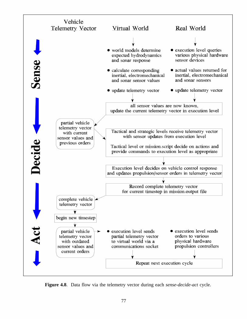
Figure 4.8. Data flow via the telemetry vector during eachsense-decide-actcycle.
77

Figure 4.9. Telemetry vector modifications during eachsense-decide-actcycle.
E. SUMMARY AND FUTURE WORK
This chapter discussed general underwater robotics hardware considerations and
software architectures. Hardware specifics of the NPS AUV are outlined.
Descriptions of NPS AUV software focus on the Rational Behavior Model (RBM)
architecture. Multiple operating system and multiple programming language strengths
and drawbacks are presented from the perspective of several years of implementation.
Significant contributions to NPS AUV execution level functionality are described in
detail, including a tactical command language and multiple dynamics control
algorithms. Specifications are then presented for communications between execution
78

level, tactical level and virtual world. A combination of two record types is shown to
be essential and complete: the telemetry vector of vehicle state, and free format
command messages. Telemetry is particularly important as the key to real-time data
transfer and interaction between the robot execution level, the underwater virtual world
and distributed users observing robot operation.
Future work includes many projects. Completing vehicle repairs and duplicating
test results from prior to the 1994 mishap are nearly complete. The execution level
program created for this dissertation needs to be reintegrated with the repaired vehicle.
Integration of GPS, internal network connections between microprocessors,
implementing strategic and tactical levels in the water, and porting sonar classification
algorithms are all planned or in progress. NPS AUV capabilities are nearly ready to
support AI research in robot architectures, sensing, classification and planning
identically in the water or in the virtual world.
79