download.firebrick.co.uk€¦ · iv table of contents preface
TRANSCRIPT

FireBrick FB2900
User Manual
FB2900 Versatile Network Appliance


FireBrick FB2900 User ManualThis User Manual documents Software version V1.48.101Copyright © 2012-2018 FireBrick Ltd.

iv
Table of ContentsPreface ................................................................................................................................. xxii1. Introduction .......................................................................................................................... 1
1.1. The FB2900 ............................................................................................................... 11.1.1. Where do I start? .............................................................................................. 11.1.2. What can it do? ................................................................................................ 11.1.3. Ethernet port capabilities .................................................................................... 21.1.4. Differences between the devices in the FB2x00 series .............................................. 21.1.5. Software features .............................................................................................. 2
1.2. About this Manual ....................................................................................................... 31.2.1. Version ........................................................................................................... 31.2.2. Intended audience ............................................................................................. 31.2.3. Technical details ............................................................................................... 31.2.4. Document style ................................................................................................. 31.2.5. Document conventions ....................................................................................... 31.2.6. Comments and feedback .................................................................................... 4
1.3. Additional Resources ................................................................................................... 41.3.1. Technical Support ............................................................................................. 41.3.2. IRC Channel .................................................................................................... 51.3.3. Application Notes ............................................................................................. 51.3.4. Training Courses ............................................................................................... 5
2. Getting Started ...................................................................................................................... 62.1. IP addressing .............................................................................................................. 62.2. Accessing the web-based user interface ........................................................................... 6
2.2.1. Setup wizard .................................................................................................... 72.2.1.1. Login username/password ........................................................................ 92.2.1.2. WAN/PPPoE settings .............................................................................. 92.2.1.3. LAN settings ......................................................................................... 92.2.1.4. Initial config .......................................................................................... 9
3. Configuration ....................................................................................................................... 103.1. The Object Hierarchy ................................................................................................. 103.2. The Object Model ...................................................................................................... 10
3.2.1. Formal definition of the object model ................................................................. 113.2.2. Common attributes .......................................................................................... 11
3.3. Configuration Methods ............................................................................................... 113.4. Data types ................................................................................................................ 11
3.4.1. Sending and receiving values ............................................................................ 123.4.2. Lists of values ................................................................................................ 123.4.3. Set of possible values ...................................................................................... 123.4.4. Dates, times, and durations ............................................................................... 123.4.5. Colours .......................................................................................................... 123.4.6. Passwords and secrets ...................................................................................... 133.4.7. IP addresses ................................................................................................... 13
3.4.7.1. Simple IP addresses .............................................................................. 133.4.7.2. Subnets and prefixes ............................................................................. 133.4.7.3. Ranges ................................................................................................ 133.4.7.4. Prefix filters ......................................................................................... 14
3.5. Web User Interface Overview ...................................................................................... 143.5.1. User Interface layout ........................................................................................ 14
3.5.1.1. Customising the layout .......................................................................... 153.5.2. Config pages and the object hierarchy ................................................................. 15
3.5.2.1. Configuration categories ......................................................................... 163.5.2.2. Object settings ...................................................................................... 17
3.5.3. Navigating around the User Interface .................................................................. 183.5.4. Backing up / restoring the configuration .............................................................. 19

FireBrick FB2900 User Manual
v
3.6. Configuration using XML ........................................................................................... 193.6.1. Introduction to XML ........................................................................................ 193.6.2. The root element - <config> ............................................................................. 203.6.3. Viewing or editing XML .................................................................................. 203.6.4. Example XML configuration ............................................................................. 21
3.7. Downloading/Uploading the configuration ...................................................................... 223.7.1. Download ...................................................................................................... 233.7.2. Upload .......................................................................................................... 23
4. System Administration .......................................................................................................... 244.1. User Management ...................................................................................................... 24
4.1.1. Login level ..................................................................................................... 244.1.2. Configuration access level ................................................................................ 254.1.3. Login idle timeout ........................................................................................... 254.1.4. Restricting user logins ...................................................................................... 25
4.1.4.1. Restrict by IP address ............................................................................ 254.1.4.2. Logged in IP address ............................................................................. 264.1.4.3. Restrict by profile ................................................................................. 26
4.1.5. Password change ............................................................................................. 264.1.6. One Time Password (OTP) ............................................................................... 26
4.2. General System settings .............................................................................................. 274.2.1. System name (hostname) .................................................................................. 274.2.2. Administrative details ...................................................................................... 274.2.3. System-level event logging control ..................................................................... 274.2.4. Home page web links ...................................................................................... 27
4.3. Software Upgrades ..................................................................................................... 284.3.1. Software release types ...................................................................................... 28
4.3.1.1. Breakpoint releases ............................................................................... 284.3.2. Identifying current software version .................................................................... 294.3.3. Internet-based upgrade process .......................................................................... 29
4.3.3.1. Manually initiating upgrades ................................................................... 294.3.3.2. Controlling automatic software updates ..................................................... 30
4.3.4. Manual upgrade .............................................................................................. 304.4. Global LED control ................................................................................................... 314.5. Boot Process ............................................................................................................. 31
4.5.1. LED indications .............................................................................................. 314.5.1.1. Status LED indications .......................................................................... 314.5.1.2. Port LEDs ........................................................................................... 32
5. Event Logging ..................................................................................................................... 335.1. Overview .................................................................................................................. 33
5.1.1. Log targets ..................................................................................................... 335.1.1.1. Logging to Flash memory ...................................................................... 335.1.1.2. Logging to the Console .......................................................................... 34
5.2. Enabling logging ....................................................................................................... 345.3. Logging to external destinations ................................................................................... 34
5.3.1. Syslog ........................................................................................................... 345.3.2. Email ............................................................................................................ 35
5.3.2.1. E-mail process logging .......................................................................... 365.4. Factory reset configuration log targets ........................................................................... 365.5. Performance .............................................................................................................. 365.6. Viewing logs ............................................................................................................. 36
5.6.1. Viewing logs in the User Interface ..................................................................... 365.6.2. Viewing logs in the CLI environment ................................................................. 37
5.7. System-event logging ................................................................................................. 375.8. Using Profiles ........................................................................................................... 37
6. Interfaces and Subnets .......................................................................................................... 386.1. Relationship between Interfaces and Physical Ports .......................................................... 38

FireBrick FB2900 User Manual
vi
6.1.1. Port groups .................................................................................................... 386.1.2. Interfaces ....................................................................................................... 38
6.2. Defining port groups .................................................................................................. 396.3. Defining an interface .................................................................................................. 39
6.3.1. Defining subnets ............................................................................................. 406.3.1.1. Source filtering ..................................................................................... 416.3.1.2. Using DHCP to configure a subnet .......................................................... 41
6.3.2. Setting up DHCP server parameters .................................................................... 416.3.2.1. Fixed/Static DHCP allocations ................................................................ 426.3.2.2. Restricted allocations ............................................................................. 436.3.2.3. Special DHCP options ........................................................................... 44
6.3.3. DHCP Relay Agent ......................................................................................... 446.4. Physical port settings .................................................................................................. 44
6.4.1. Disabling auto-negotiation ................................................................................ 456.4.2. Setting port speed ............................................................................................ 456.4.3. Setting duplex mode ........................................................................................ 456.4.4. Defining port LED functions ............................................................................. 45
7. Session Handling ................................................................................................................. 487.1. Routing vs. Firewalling ............................................................................................... 487.2. Session Tracking ....................................................................................................... 48
7.2.1. Session termination .......................................................................................... 497.3. Session Rules ............................................................................................................ 49
7.3.1. Overview ....................................................................................................... 497.3.2. Processing flow ............................................................................................... 507.3.3. Defining Rule-Sets and Rules ............................................................................ 53
7.3.3.1. Recommended method of implementing firewalling .................................... 547.3.3.2. Changes to session traffic ....................................................................... 557.3.3.3. Graphing and traffic shaping ................................................................... 567.3.3.4. Configuring session time-outs ................................................................. 567.3.3.5. Load balancing ..................................................................................... 577.3.3.6. NAT-PMP / PCP (Port Control Protocol) .................................................. 57
7.4. Network Address Translation ....................................................................................... 587.4.1. When to use NAT ........................................................................................... 587.4.2. NAT ALGs .................................................................................................... 597.4.3. Setting NAT in rules ........................................................................................ 597.4.4. What NAT does .............................................................................................. 597.4.5. NAT with PPPoE ............................................................................................ 607.4.6. NAT with Dongles .......................................................................................... 607.4.7. NAT with other types of external routing ............................................................ 607.4.8. Mixing NAT and non NAT ............................................................................... 607.4.9. Carrier grade NAT .......................................................................................... 617.4.10. Using NAT setting on subnets ......................................................................... 61
8. Routing .............................................................................................................................. 628.1. Routing logic ............................................................................................................ 628.2. Routing targets .......................................................................................................... 63
8.2.1. Subnet routes .................................................................................................. 638.2.2. Routing to an IP address (gateway route) ............................................................. 638.2.3. Special targets ................................................................................................ 64
8.3. Dynamic route creation / deletion ................................................................................. 648.4. Routing tables ........................................................................................................... 648.5. Bonding ................................................................................................................... 648.6. Route overrides ......................................................................................................... 65
9. Profiles ............................................................................................................................... 669.1. Overview .................................................................................................................. 669.2. Creating/editing profiles .............................................................................................. 66
9.2.1. Timing control ................................................................................................ 66

FireBrick FB2900 User Manual
vii
9.2.2. Tests ............................................................................................................. 679.2.2.1. General tests ........................................................................................ 679.2.2.2. Time/date tests ..................................................................................... 679.2.2.3. Ping tests ............................................................................................. 67
9.2.3. Inverting overall test result ................................................................................ 689.2.4. Manual override .............................................................................................. 689.2.5. LED .............................................................................................................. 68
10. Traffic Shaping .................................................................................................................. 6910.1. Graphs and Shapers .................................................................................................. 69
10.1.1. Graphs ......................................................................................................... 6910.1.2. Shapers ........................................................................................................ 7010.1.3. Ad hoc shapers ............................................................................................. 7010.1.4. Long term shapers ......................................................................................... 70
10.2. Multiple shapers ...................................................................................................... 7110.3. Basic principles ....................................................................................................... 71
11. PPPoE .............................................................................................................................. 7211.1. Types of DSL line and router in the United Kingdom ..................................................... 7211.2. Definining PPPoE links ............................................................................................. 73
11.2.1. IPv6 ............................................................................................................ 7311.2.2. Additional options ......................................................................................... 73
11.2.2.1. MTU and TCP fix ............................................................................... 7311.2.2.2. Service and ac-name ............................................................................ 7411.2.2.3. Logging ............................................................................................. 7411.2.2.4. Speed and graphs ................................................................................ 74
12. Tunnels ............................................................................................................................. 7512.1. IPsec (IP Security) ................................................................................................... 75
12.1.1. Introduction .................................................................................................. 7512.1.1.1. Integrity checking ................................................................................ 7512.1.1.2. Encryption ......................................................................................... 7512.1.1.3. Authentication .................................................................................... 7612.1.1.4. IKE ................................................................................................... 7612.1.1.5. Manual Keying ................................................................................... 7612.1.1.6. Identities and the Authentication Mechanism ............................................ 77
12.1.2. Setting up IPsec connections ........................................................................... 7712.1.2.1. Global IPsec parameters ....................................................................... 7712.1.2.2. IKE proposals ..................................................................................... 7812.1.2.3. IKE roaming IP pools .......................................................................... 7812.1.2.4. IKE connections .................................................................................. 78
12.1.2.4.1. IKE connection mode and type ................................................... 7812.1.2.4.2. IKE and IPsec proposal lists ....................................................... 7812.1.2.4.3. Authentication and IKE identities ................................................ 7912.1.2.4.4. IP addresses ............................................................................. 8012.1.2.4.5. Road Warrior connections .......................................................... 8012.1.2.4.6. Routing ................................................................................... 8012.1.2.4.7. Other parameters ...................................................................... 80
12.1.2.5. Setting up Manual Keying .................................................................... 8112.1.2.5.1. IP endpoints ............................................................................. 8112.1.2.5.2. Algorithms and keys ................................................................. 8112.1.2.5.3. Routing ................................................................................... 8112.1.2.5.4. Mode ...................................................................................... 8212.1.2.5.5. Other parameters ...................................................................... 82
12.1.3. Using EAP with IPsec/IKE ............................................................................. 8212.1.4. Using certificates with IPsec/IKE ..................................................................... 82
12.1.4.1. Creating certificates ............................................................................. 8412.1.5. Choice of algorithms ...................................................................................... 8512.1.6. NAT Traversal .............................................................................................. 86

FireBrick FB2900 User Manual
viii
12.1.7. Configuring a Road Warrior server ................................................................... 8612.1.8. Connecting to non-FireBrick devices ................................................................. 88
12.1.8.1. Using StrongSwan on Linux ................................................................. 8812.1.8.2. Setting up a Road Warrior VPN on an Android client ................................ 8912.1.8.3. Setting up a Road Warrior VPN on an iOS (iPhone/iPad) client .................... 8912.1.8.4. Manual keying using Linux ipsec-tools ................................................... 90
12.2. FB105 tunnels ......................................................................................................... 9112.2.1. Tunnel wrapper packets .................................................................................. 9112.2.2. Setting up a tunnel ......................................................................................... 9212.2.3. Viewing tunnel status ..................................................................................... 9212.2.4. Dynamic routes ............................................................................................. 9312.2.5. Tunnel bonding ............................................................................................. 9312.2.6. Tunnels and NAT .......................................................................................... 93
12.2.6.1. FB2900 doing NAT ............................................................................. 9312.2.6.2. Another device doing NAT ................................................................... 94
12.3. Ether tunnelling ....................................................................................................... 9413. USB Port .......................................................................................................................... 95
13.1. USB configuration .................................................................................................... 9513.1.1. 3G dongle configuration ................................................................................. 95
14. System Services ................................................................................................................. 9614.1. Protecting the FB2900 .............................................................................................. 9614.2. Common settings ..................................................................................................... 9614.3. HTTP Server configuration ........................................................................................ 97
14.3.1. Access control ............................................................................................... 9714.3.1.1. Trusted addresses ................................................................................ 97
14.3.2. HTTPS access ............................................................................................... 9814.4. Telnet Server configuration ........................................................................................ 99
14.4.1. Access control ............................................................................................... 9914.5. DNS configuration ................................................................................................... 99
14.5.1. Blocking DNS names ................................................................................... 10014.5.2. Local DNS responses .................................................................................... 10014.5.3. Auto DHCP DNS ........................................................................................ 100
14.6. NTP configuration .................................................................................................. 10014.7. SNMP configuration ............................................................................................... 10014.8. RADIUS configuration ............................................................................................ 101
14.8.1. RADIUS server (platform RADIUS) ............................................................... 10114.8.2. RADIUS client ............................................................................................ 101
14.8.2.1. RADIUS client settings ...................................................................... 10114.8.2.2. Server blacklisting ............................................................................. 102
15. Network Diagnostic Tools .................................................................................................. 10315.1. Firewalling check ................................................................................................... 10315.2. Access check ......................................................................................................... 10415.3. Packet Dumping ..................................................................................................... 104
15.3.1. Dump parameters ......................................................................................... 10515.3.2. Security settings required .............................................................................. 10515.3.3. IP address matching ..................................................................................... 10615.3.4. Packet types ................................................................................................ 10615.3.5. Snaplen specification .................................................................................... 10615.3.6. Using the web interface ................................................................................ 10615.3.7. Using an HTTP client ................................................................................... 106
15.3.7.1. Example using curl and tcpdump .......................................................... 10716. VRRP ............................................................................................................................. 108
16.1. Virtual Routers ...................................................................................................... 10816.2. Configuring VRRP ................................................................................................. 109
16.2.1. Advertisement Interval .................................................................................. 10916.2.2. Priority ....................................................................................................... 109

FireBrick FB2900 User Manual
ix
16.3. Using a virtual router .............................................................................................. 10916.4. VRRP versions ...................................................................................................... 109
16.4.1. VRRP version 2 .......................................................................................... 10916.4.2. VRRP version 3 .......................................................................................... 110
16.5. Compatibility ......................................................................................................... 11017. VoIP ............................................................................................................................... 111
17.1. What is VoIP? ....................................................................................................... 11117.2. Registration and Proxies .......................................................................................... 111
17.2.1. Registrar ..................................................................................................... 11117.2.2. Proxy ......................................................................................................... 111
17.3. Home/office phone system ....................................................................................... 11217.4. Network Address Translation .................................................................................... 11217.5. Number plan .......................................................................................................... 11317.6. Telephone handsets ................................................................................................. 11317.7. VoIP call carriers ................................................................................................... 11417.8. Hunt groups ........................................................................................................... 115
17.8.1. Ring Type .................................................................................................. 11517.8.2. Ring order .................................................................................................. 11617.8.3. Overflow .................................................................................................... 11617.8.4. Out of hours ............................................................................................... 116
17.9. Call pickup/steal ..................................................................................................... 11617.10. Busy lamp field .................................................................................................... 11717.11. Using RADIUS .................................................................................................... 117
17.11.1. RADIUS accounting ................................................................................... 11717.11.2. RADIUS authentication ............................................................................... 117
17.11.2.1. Call routing by RADIUS ................................................................... 11817.12. Call recording ...................................................................................................... 11917.13. Voicemail and IVR services ................................................................................... 12017.14. Call Data Records ................................................................................................. 12017.15. Technical details ................................................................................................... 12117.16. Custom tones ....................................................................................................... 121
18. BGP ............................................................................................................................... 12318.1. What is BGP? ........................................................................................................ 12318.2. BGP Setup ............................................................................................................ 123
18.2.1. Overview .................................................................................................... 12318.2.2. Standards .................................................................................................... 12318.2.3. Simple example setup ................................................................................... 12418.2.4. Peer type .................................................................................................... 12418.2.5. Route filtering ............................................................................................. 125
18.2.5.1. Matching attributes ............................................................................ 12518.2.5.2. Action attributes ................................................................................ 125
18.2.6. Well known community tags .......................................................................... 12618.2.7. Announcing black hole routes ........................................................................ 12618.2.8. Grey holes .................................................................................................. 12718.2.9. Announcing dead end routes .......................................................................... 12718.2.10. Bad optional path attributes .......................................................................... 12718.2.11. <network> element ..................................................................................... 12718.2.12. <route>, <subnet> and other elements ............................................................ 12818.2.13. Route feasibility testing ............................................................................... 12818.2.14. Diagnostics ................................................................................................ 12818.2.15. Router shutdown ........................................................................................ 12818.2.16. TTL security ............................................................................................. 128
19. OSPF .............................................................................................................................. 13019.1. What is OSPF? ...................................................................................................... 13019.2. OSPF Setup ........................................................................................................... 130
19.2.1. Overview .................................................................................................... 130

FireBrick FB2900 User Manual
x
19.2.2. Standards .................................................................................................... 13019.2.3. Simple example setup ................................................................................... 13119.2.4. <ospf> configelement ................................................................................... 131
20. Internet Service Providers ................................................................................................... 13220.1. Background ........................................................................................................... 132
20.1.1. How it all began .......................................................................................... 13220.1.2. Point to Point Protocol .................................................................................. 13220.1.3. L2TP ......................................................................................................... 13220.1.4. Broadband .................................................................................................. 13320.1.5. RADIUS ..................................................................................................... 13320.1.6. BGP .......................................................................................................... 133
20.2. Incoming L2TP connections ..................................................................................... 13320.3. The importance of CQM graphs ................................................................................ 13420.4. Authentication ........................................................................................................ 13420.5. Accounting ............................................................................................................ 13520.6. RADIUS Control messages ...................................................................................... 13520.7. PPPoE .................................................................................................................. 13520.8. Typical configuration .............................................................................................. 135
20.8.1. Interlink subnet ............................................................................................ 13520.8.2. BGP with carrier .......................................................................................... 13620.8.3. RADIUS session steering .............................................................................. 13620.8.4. L2TP endpoints ........................................................................................... 13720.8.5. ISP RADIUS ............................................................................................... 137
21. Command Line Interface .................................................................................................... 138A. Factory Reset Procedure ...................................................................................................... 139B. CIDR and CIDR Notation ................................................................................................... 141C. MAC Addresses usage ........................................................................................................ 143
C.1. Multiple MAC addresses? ......................................................................................... 143C.2. How the FireBrick allocates MAC addresses ................................................................ 144
C.2.1. Interface ...................................................................................................... 144C.2.2. Subnet ......................................................................................................... 144C.2.3. PPPoE ......................................................................................................... 144C.2.4. Base MAC ................................................................................................... 144C.2.5. Running out of MACs ................................................................................... 145
C.3. MAC address on label .............................................................................................. 145C.4. Using with a DHCP server ........................................................................................ 145
D. Scripted access .................................................................................................................. 146D.1. Tools ..................................................................................................................... 146D.2. Access control ........................................................................................................ 146
D.2.1. Username and password ................................................................................. 146D.2.2. OTP ............................................................................................................ 146D.2.3. Allow list .................................................................................................... 146D.2.4. Allowed access ............................................................................................. 146
D.3. XML data for common functions ............................................................................... 146D.4. XML data from diagnostics and tests .......................................................................... 147
D.4.1. Cross site scripting security ............................................................................ 147D.4.2. Arguments to scripts ...................................................................................... 147
D.5. Special URLs ......................................................................................................... 148D.6. Web sockets ........................................................................................................... 148
E. VLANs : A primer ............................................................................................................. 149F. Supported L2TP Attribute/Value Pairs ................................................................................... 150
F.1. Start-Control-Connection-Request ............................................................................... 150F.2. Start-Control-Connection-Reply .................................................................................. 150F.3. Start-Control-Connection-Connected ............................................................................ 151F.4. Stop-Control-Connection-Notification .......................................................................... 151F.5. Hello ..................................................................................................................... 151

FireBrick FB2900 User Manual
xi
F.6. Incoming-Call-Request .............................................................................................. 151F.7. Incoming-Call-Reply ................................................................................................ 152F.8. Incoming-Call-Connected .......................................................................................... 152F.9. Outgoing-Call-Request .............................................................................................. 152F.10. Outgoing-Call-Reply ............................................................................................... 153F.11. Outgoing-Call-Connected ......................................................................................... 153F.12. Call-Disconnect-Notify ............................................................................................ 153F.13. WAN-Error-Notify ................................................................................................. 153F.14. Set-Link-Info ......................................................................................................... 153F.15. Notes ................................................................................................................... 154
F.15.1. BT specific notes ......................................................................................... 154F.15.2. IP over LCP ............................................................................................... 154
G. Supported RADIUS Attribute/Value Pairs for L2TP operation ................................................... 155G.1. Authentication request .............................................................................................. 155G.2. Authentication response ............................................................................................ 156
G.2.1. Accepted authentication ................................................................................. 156G.2.1.1. Prefix Delegation ................................................................................ 157
G.2.2. Rejected authentication .................................................................................. 158G.3. Accounting Start ..................................................................................................... 158G.4. Accounting Interim .................................................................................................. 159G.5. Accounting Stop ...................................................................................................... 160G.6. Disconnect ............................................................................................................. 160G.7. Change of Authorisation ........................................................................................... 160G.8. Filter ID ................................................................................................................ 161G.9. Notes ..................................................................................................................... 162
G.9.1. L2TP relay .................................................................................................. 162G.9.2. LCP echo and CQM graphs ............................................................................ 163G.9.3. IP over LCP ................................................................................................. 163G.9.4. Closed User Group ........................................................................................ 164G.9.5. Routing table ............................................................................................... 164
H. Supported RADIUS Attribute/Value Pairs for VoIP operation .................................................... 165H.1. Authentication request .............................................................................................. 165H.2. Authentication response ............................................................................................ 166
H.2.1. Challenge authentication ................................................................................ 166H.2.2. Accepted authentication (registration) ............................................................... 166H.2.3. Accepted authentication (invite) ....................................................................... 166H.2.4. Rejected authentication .................................................................................. 167
H.3. Accounting Start ..................................................................................................... 167H.4. Accounting Interim .................................................................................................. 167H.5. Accounting Stop ...................................................................................................... 168H.6. Disconnect ............................................................................................................. 168H.7. Change of Authorisation ........................................................................................... 169
I. FireBrick specific SNMP objects ........................................................................................... 170I.1. BGP information ...................................................................................................... 170I.2. L2TP information ..................................................................................................... 170I.3. VoIP information ...................................................................................................... 171
J. Command line reference ...................................................................................................... 172J.1. General commands ................................................................................................... 172
J.1.1. Trace off ...................................................................................................... 172J.1.2. Trace on ....................................................................................................... 172J.1.3. Uptime ......................................................................................................... 172J.1.4. General status ................................................................................................ 172J.1.5. Memory usage ............................................................................................... 172J.1.6. Process/task usage .......................................................................................... 172J.1.7. Login ........................................................................................................... 172J.1.8. Logout ......................................................................................................... 173

FireBrick FB2900 User Manual
xii
J.1.9. See XML configuration ................................................................................... 173J.1.10. Load XML configuration ............................................................................... 173J.1.11. Show profile status ....................................................................................... 173J.1.12. Enable profile control switch .......................................................................... 173J.1.13. Disable profile control switch ......................................................................... 173J.1.14. Show RADIUS servers .................................................................................. 173J.1.15. Show DNS resolvers ..................................................................................... 173
J.2. Networking commands .............................................................................................. 174J.2.1. Subnets ........................................................................................................ 174J.2.2. Ping and trace ............................................................................................... 174J.2.3. Show a route from the routing table .................................................................. 174J.2.4. List routes .................................................................................................... 174J.2.5. List routing next hops ..................................................................................... 174J.2.6. See DHCP allocations ..................................................................................... 175J.2.7. Clear DHCP allocations .................................................................................. 175J.2.8. Lock DHCP allocations ................................................................................... 175J.2.9. Unlock DHCP allocations ................................................................................ 175J.2.10. Name DHCP allocations ................................................................................ 175J.2.11. Show ARP/ND status .................................................................................... 175J.2.12. Show VRRP status ....................................................................................... 175J.2.13. Send Wake-on-LAN packet ............................................................................ 175
J.3. Firewalling commands ............................................................................................... 176J.3.1. Check access to services ................................................................................. 176J.3.2. Check firewall logic ....................................................................................... 176
J.4. USB/dongle commands ............................................................................................. 176J.4.1. Show dongle connectoons ............................................................................... 176J.4.2. Reset USB interface and all attached devices ...................................................... 176J.4.3. Reset PPP/Dongle data connection .................................................................... 176
J.5. L2TP commands ...................................................................................................... 176J.6. BGP commands ....................................................................................................... 176J.7. OSPF commands ...................................................................................................... 177J.8. PPPoE commands ..................................................................................................... 177J.9. VoIP commands ....................................................................................................... 177J.10. Dongle/USB commands ........................................................................................... 177J.11. Advanced commands ............................................................................................... 177
J.11.1. Panic .......................................................................................................... 177J.11.2. Reboot ........................................................................................................ 177J.11.3. Screen width ............................................................................................... 177J.11.4. Make outbound command session ................................................................... 178J.11.5. Show command sessions ............................................................................... 178J.11.6. Kill command session ................................................................................... 178J.11.7. Flash memory list ......................................................................................... 178J.11.8. Delete block from flash ................................................................................. 178J.11.9. Boot log ..................................................................................................... 178J.11.10. Flash log ................................................................................................... 178
K. Constant Quality Monitoring - technical details ....................................................................... 179K.1. Broadband back-haul providers .................................................................................. 179K.2. Access to graphs and csvs ........................................................................................ 179
K.2.1. Trusted access .............................................................................................. 179K.2.2. Dated information ......................................................................................... 180K.2.3. Authenticated access ...................................................................................... 180
K.3. Graph display options .............................................................................................. 180K.3.1. Scaleable Vector Graphics .............................................................................. 180K.3.2. Data points .................................................................................................. 181K.3.3. Additional text ............................................................................................. 181K.3.4. Other colours and spacing .............................................................................. 181

FireBrick FB2900 User Manual
xiii
K.4. Overnight archiving ................................................................................................. 182K.4.1. Full URL format ........................................................................................... 182K.4.2. load handling ............................................................................................... 183
K.5. Graph scores ........................................................................................................... 183K.6. Creating graphs, and graph names .............................................................................. 183
L. Hashed passwords .............................................................................................................. 184L.1. Password hashing .................................................................................................... 184
L.1.1. Salt ............................................................................................................. 184L.2. One Time Password seed hashing ............................................................................... 185
M. Configuration Objects ........................................................................................................ 187M.1. Top level ............................................................................................................... 187
M.1.1. config: Top level config ................................................................................ 187M.2. Objects .................................................................................................................. 188
M.2.1. system: System settings ................................................................................. 188M.2.2. link: Web links ............................................................................................ 190M.2.3. user: Admin users ........................................................................................ 190M.2.4. eap: User access controlled by EAP ................................................................. 190M.2.5. log: Log target controls ................................................................................. 191M.2.6. log-syslog: Syslog logger settings .................................................................... 191M.2.7. log-email: Email logger settings ...................................................................... 192M.2.8. services: System services ............................................................................... 192M.2.9. http-service: Web service settings .................................................................... 193M.2.10. dns-service: DNS service settings .................................................................. 193M.2.11. dns-host: Fixed local DNS host settings .......................................................... 194M.2.12. dns-block: Fixed local DNS blocks ................................................................ 195M.2.13. radius-service: RADIUS service definition ...................................................... 195M.2.14. radius-service-match: Matching rules for RADIUS service ................................. 196M.2.15. radius-server: RADIUS server settings ............................................................ 198M.2.16. telnet-service: Telnet service settings .............................................................. 198M.2.17. snmp-service: SNMP service settings ............................................................. 199M.2.18. ntp-service: NTP service settings ................................................................... 199M.2.19. ethernet: Physical port controls ..................................................................... 200M.2.20. link-activity: LED link monitoring ................................................................. 201M.2.21. sampling: Packet sampling configuration ........................................................ 201M.2.22. portdef: Port grouping and naming ................................................................. 202M.2.23. interface: Port-group/VLAN interface settings .................................................. 202M.2.24. subnet: Subnet settings ................................................................................ 203M.2.25. vrrp: VRRP settings .................................................................................... 204M.2.26. dhcps: DHCP server settings ......................................................................... 205M.2.27. dhcp-attr-hex: DHCP server attributes (hex) .................................................... 206M.2.28. dhcp-attr-string: DHCP server attributes (string) ............................................... 206M.2.29. dhcp-attr-number: DHCP server attributes (numeric) ......................................... 207M.2.30. dhcp-attr-ip: DHCP server attributes (IP) ........................................................ 207M.2.31. pppoe: PPPoE settings ................................................................................. 207M.2.32. ppp-route: PPP routes .................................................................................. 208M.2.33. usb: USB 3G/dongle settings ........................................................................ 209M.2.34. dongle: 3G/dongle settings ........................................................................... 209M.2.35. route: Static routes ...................................................................................... 210M.2.36. network: Locally originated networks ............................................................. 211M.2.37. blackhole: Dead end networks ....................................................................... 211M.2.38. loopback: Locally originated networks ............................................................ 212M.2.39. ospf: Overall OSPF settings .......................................................................... 212M.2.40. namedbgpmap: Mapping and filtering rules of BGP prefixes ............................... 213M.2.41. bgprule: Individual mapping/filtering rule ....................................................... 214M.2.42. bgp: Overall BGP settings ............................................................................ 214M.2.43. bgppeer: BGP peer definitions ...................................................................... 215

FireBrick FB2900 User Manual
xiv
M.2.44. bgpmap: Mapping and filtering rules of BGP prefixes ....................................... 217M.2.45. cqm: Constant Quality Monitoring settings ...................................................... 217M.2.46. l2tp: L2TP settings ...................................................................................... 219M.2.47. l2tp-outgoing: L2TP settings for outgoing L2TP connections .............................. 219M.2.48. l2tp-incoming: L2TP settings for incoming L2TP connections ............................. 221M.2.49. l2tp-relay: Relay and local authentication rules for L2TP ................................... 222M.2.50. fb105: FB105 tunnel definition ..................................................................... 223M.2.51. fb105-route: FB105 routes ............................................................................ 224M.2.52. ipsec-ike: IPsec configuration (IKEv2) ........................................................... 225M.2.53. ike-connection: connection configuration ........................................................ 226M.2.54. ipsec-route: IPsec tunnel routes ..................................................................... 227M.2.55. ike-roaming: IKE roaming IP pools ................................................................ 227M.2.56. ike-proposal: IKE security proposal ............................................................... 228M.2.57. ipsec-proposal: IPsec AH/ESP proposal .......................................................... 228M.2.58. ipsec-manual: peer configuration ................................................................... 228M.2.59. ping: Ping/graph definition ........................................................................... 230M.2.60. profile: Control profile ................................................................................. 230M.2.61. profile-date: Test passes if within any of the time ranges specified ....................... 231M.2.62. profile-time: Test passes if within any of the date/time ranges specified ................. 232M.2.63. profile-ping: Test passes if any addresses are pingable ....................................... 232M.2.64. shaper: Traffic shaper .................................................................................. 232M.2.65. shaper-override: Traffic shaper override based on profile ................................... 233M.2.66. ip-group: IP Group ...................................................................................... 233M.2.67. route-override: Routing override rules ............................................................ 234M.2.68. session-route-rule: Routing override rule ......................................................... 234M.2.69. session-route-share: Route override load sharing ............................................... 235M.2.70. rule-set: Firewall/mapping rule set ................................................................. 235M.2.71. session-rule: Firewall rules ........................................................................... 236M.2.72. session-share: Firewall load sharing ............................................................... 237M.2.73. voip: Voice over IP config ........................................................................... 238M.2.74. carrier: VoIP carrier details .......................................................................... 239M.2.75. telephone: VoIP telephone authentication user details ........................................ 241M.2.76. tone: Tone definitions .................................................................................. 242M.2.77. ringgroup: Ring groups ................................................................................ 242M.2.78. etun: Ether tunnel ....................................................................................... 243M.2.79. dhcp-relay: DHCP server settings for remote / relayed requests ........................... 243
M.3. Data types ............................................................................................................. 244M.3.1. autoloadtype: Type of s/w auto load ................................................................ 244M.3.2. config-access: Type of access user has to config ................................................ 244M.3.3. user-level: User login level ............................................................................ 244M.3.4. eap-subsystem: Subsystem with EAP access control ........................................... 245M.3.5. eap-method: EAP access method ..................................................................... 245M.3.6. syslog-severity: Syslog severity ....................................................................... 245M.3.7. syslog-facility: Syslog facility ......................................................................... 245M.3.8. http-mode: HTTP/HTTPS security mode .......................................................... 246M.3.9. radiuspriority: Options for controlling platform RADIUS response prioritytagging ................................................................................................................. 246M.3.10. radiustype: Type of RADIUS server ............................................................... 247M.3.11. month: Month name (3 letter) ....................................................................... 247M.3.12. day: Day name (3 letter) .............................................................................. 247M.3.13. port: Physical port ...................................................................................... 248M.3.14. Crossover: Crossover configuration ................................................................ 248M.3.15. LinkSpeed: Physical port speed ..................................................................... 248M.3.16. LinkDuplex: Physical port duplex setting ........................................................ 248M.3.17. LinkFlow: Physical port flow control setting .................................................... 249M.3.18. LinkClock: Physical port Gigabit clock master/slave setting ................................ 249

FireBrick FB2900 User Manual
xv
M.3.19. LinkLED: LED settings ............................................................................... 249M.3.20. LinkPower: PHY power saving options .......................................................... 249M.3.21. LinkFault: Link fault type to send .................................................................. 249M.3.22. LEDColour: Which colour LED .................................................................... 250M.3.23. LEDBlink: LED blink speed ......................................................................... 250M.3.24. sampling-protocol: Sampling protocol ............................................................ 250M.3.25. trunk-mode: Trunk port mode ....................................................................... 250M.3.26. ramode: IPv6 route announce level ................................................................ 250M.3.27. dhcpv6control: Control for RA and DHCPv6 bits ............................................. 251M.3.28. bgpmode: BGP announcement mode .............................................................. 251M.3.29. sampling-mode: Sampling mode .................................................................... 251M.3.30. sfoption: Source filter option ........................................................................ 251M.3.31. pppoe-mode: Type of PPPoE connection ......................................................... 252M.3.32. pdp-context-type: Type of IP connection ......................................................... 252M.3.33. ipsec-type: IPsec encapsulation type ............................................................... 252M.3.34. ipsec-auth-algorithm: IPsec authentication algorithm ......................................... 252M.3.35. ipsec-crypt-algorithm: IPsec encryption algorithm ............................................. 252M.3.36. peertype: BGP peer type .............................................................................. 253M.3.37. radius-nas: NAS IP to report ......................................................................... 253M.3.38. ike-authmethod: authentication method ........................................................... 253M.3.39. ike-mode: connection setup mode .................................................................. 254M.3.40. ike-PRF: IKE Pseudo-Random Function ......................................................... 254M.3.41. ike-DH: IKE Diffie-Hellman group ................................................................ 254M.3.42. ike-ESN: IKE Sequence Number support ........................................................ 254M.3.43. ipsec-encapsulation: Manually keyed IPsec encapsulation mode .......................... 254M.3.44. switch: Profile manual setting ....................................................................... 255M.3.45. dynamic-graph: Type of dynamic graph .......................................................... 255M.3.46. firewall-action: Firewall action ...................................................................... 255M.3.47. voip-format: Number presentation format ........................................................ 255M.3.48. uknumberformat: Number formatting option .................................................... 255M.3.49. recordoption: Recording option ..................................................................... 256M.3.50. ring-group-order: Order of ring ..................................................................... 256M.3.51. ring-group-type: Type of ring when one call in queue ........................................ 256M.3.52. record-beep-option: Record beep option .......................................................... 256
M.4. Basic types ............................................................................................................ 257Index .................................................................................................................................... 260

xvi
List of Figures2.1. Initial web page in factory reset state ...................................................................................... 72.2. Setup Wizard ...................................................................................................................... 83.1. Main menu ....................................................................................................................... 153.2. Icons for layout controls ..................................................................................................... 153.3. Icons for configuration categories ......................................................................................... 163.4. The "Setup" category .......................................................................................................... 163.5. Editing an "Interface" object ................................................................................................ 173.6. Show hidden attributes ....................................................................................................... 173.7. Attribute definitions ........................................................................................................... 183.8. Navigation controls ............................................................................................................ 184.1. Setting up a new user ......................................................................................................... 244.2. Software upgrade available notification ................................................................................. 304.3. Manual Software upload ..................................................................................................... 317.1. Example sessions created by drop and reject actions ................................................................ 507.2. Processing flow chart for rule-sets and session-rules ................................................................ 52C.1. Product label showing MAC address range .......................................................................... 145

xvii
List of Tables2.1. IP addresses for computer ..................................................................................................... 62.2. IP addresses to access the FireBrick ....................................................................................... 62.3. IP addresses to access the FireBrick ....................................................................................... 63.1. Special character sequences ................................................................................................. 204.1. User login levels ............................................................................................................... 254.2. Configuration access levels .................................................................................................. 254.3. General administrative details attributes ................................................................................. 274.4. Attributes controlling auto-upgrades ...................................................................................... 304.5. Global LED control ........................................................................................................... 314.6. Status LED indications ....................................................................................................... 315.1. Logging attributes .............................................................................................................. 345.2. System-Event Logging attributes .......................................................................................... 376.1. Port LED functions ............................................................................................................ 456.2. LED Link/Activity settings .................................................................................................. 466.3. Example modified Port LED functions .................................................................................. 477.1. Action attribute values ........................................................................................................ 508.1. Example route targets ......................................................................................................... 6312.1. IPsec algorithm key lengths ............................................................................................... 8112.2. IKE / IPsec algorithm proposals .......................................................................................... 8514.1. List of system services ...................................................................................................... 9614.2. List of system services ...................................................................................................... 9715.1. Packet dump parameters .................................................................................................. 10515.2. Packet types that can be captured ...................................................................................... 10617.1. Ring Type ..................................................................................................................... 11517.2. Ring Order .................................................................................................................... 11617.3. Access-Accept ............................................................................................................... 11917.4. Default tones ................................................................................................................. 12118.1. Peer types ..................................................................................................................... 12418.2. Communities ................................................................................................................. 12618.3. Network attributes .......................................................................................................... 12719.1. OSPF config attributes .................................................................................................... 131C.1. DHCP client names used .................................................................................................. 145D.1. Special URLs ................................................................................................................. 148F.1. SCCRQ .......................................................................................................................... 150F.2. SCCRP .......................................................................................................................... 150F.3. SCCCN .......................................................................................................................... 151F.4. StopCCN ........................................................................................................................ 151F.5. HELLO .......................................................................................................................... 151F.6. ICRQ ............................................................................................................................. 151F.7. ICRP ............................................................................................................................. 152F.8. ICCN ............................................................................................................................. 152F.9. OCRQ ............................................................................................................................ 152F.10. OCRP .......................................................................................................................... 153F.11. OCCN .......................................................................................................................... 153F.12. CDN ............................................................................................................................ 153F.13. WEN ............................................................................................................................ 153F.14. SLI .............................................................................................................................. 153G.1. Access-request ................................................................................................................ 155G.2. Access-Accept ................................................................................................................ 156G.3. Access-Reject ................................................................................................................. 158G.4. Accounting-Start ............................................................................................................. 158G.5. Accounting-Interim .......................................................................................................... 159G.6. Accounting-Stop .............................................................................................................. 160G.7. Disconnect ..................................................................................................................... 160

FireBrick FB2900 User Manual
xviii
G.8. Change-of-Authorisation ................................................................................................... 160G.9. Filter-ID ........................................................................................................................ 161H.1. Access-request ................................................................................................................ 165H.2. Access-Challenge ............................................................................................................ 166H.3. Access-Accept ................................................................................................................ 166H.4. Access-Accept ................................................................................................................ 166H.5. Access-Reject ................................................................................................................. 167H.6. Accounting-Start ............................................................................................................. 167H.7. Accounting-Interim .......................................................................................................... 167H.8. Accounting-Stop .............................................................................................................. 168H.9. Disconnect ..................................................................................................................... 168H.10. Change-of-Authorisation ................................................................................................. 169I.1. iso.3.6.1.4.1.24693.179 ...................................................................................................... 170I.2. iso.3.6.1.4.1.24693.1701 ..................................................................................................... 170I.3. iso.3.6.1.4.1.24693.5060 ..................................................................................................... 171K.1. File types ....................................................................................................................... 179K.2. Colours .......................................................................................................................... 181K.3. Text .............................................................................................................................. 181K.4. Text .............................................................................................................................. 181K.5. URL formats .................................................................................................................. 182M.1. config: Attributes ............................................................................................................ 187M.2. config: Elements ............................................................................................................. 187M.3. system: Attributes ........................................................................................................... 188M.4. system: Elements ............................................................................................................ 189M.5. link: Attributes ............................................................................................................... 190M.6. user: Attributes ............................................................................................................... 190M.7. eap: Attributes ................................................................................................................ 190M.8. log: Attributes ................................................................................................................ 191M.9. log: Elements ................................................................................................................. 191M.10. log-syslog: Attributes ..................................................................................................... 191M.11. log-email: Attributes ...................................................................................................... 192M.12. services: Elements ......................................................................................................... 192M.13. http-service: Attributes ................................................................................................... 193M.14. dns-service: Attributes .................................................................................................... 194M.15. dns-service: Elements ..................................................................................................... 194M.16. dns-host: Attributes ....................................................................................................... 194M.17. dns-block: Attributes ...................................................................................................... 195M.18. radius-service: Attributes ................................................................................................ 195M.19. radius-service: Elements ................................................................................................. 196M.20. radius-service-match: Attributes ....................................................................................... 196M.21. radius-server: Attributes ................................................................................................. 198M.22. telnet-service: Attributes ................................................................................................. 198M.23. snmp-service: Attributes ................................................................................................. 199M.24. ntp-service: Attributes .................................................................................................... 199M.25. ethernet: Attributes ........................................................................................................ 200M.26. link-activity: Attributes .................................................................................................. 201M.27. sampling: Attributes ....................................................................................................... 201M.28. portdef: Attributes ......................................................................................................... 202M.29. interface: Attributes ....................................................................................................... 202M.30. interface: Elements ........................................................................................................ 203M.31. subnet: Attributes .......................................................................................................... 203M.32. vrrp: Attributes ............................................................................................................. 204M.33. dhcps: Attributes ........................................................................................................... 205M.34. dhcps: Elements ............................................................................................................ 206M.35. dhcp-attr-hex: Attributes ................................................................................................. 206M.36. dhcp-attr-string: Attributes .............................................................................................. 206

FireBrick FB2900 User Manual
xix
M.37. dhcp-attr-number: Attributes ........................................................................................... 207M.38. dhcp-attr-ip: Attributes ................................................................................................... 207M.39. pppoe: Attributes ........................................................................................................... 207M.40. pppoe: Elements ............................................................................................................ 208M.41. ppp-route: Attributes ...................................................................................................... 209M.42. usb: Attributes .............................................................................................................. 209M.43. usb: Elements ............................................................................................................... 209M.44. dongle: Attributes .......................................................................................................... 209M.45. dongle: Elements ........................................................................................................... 210M.46. route: Attributes ............................................................................................................ 211M.47. network: Attributes ........................................................................................................ 211M.48. blackhole: Attributes ...................................................................................................... 211M.49. loopback: Attributes ....................................................................................................... 212M.50. ospf: Attributes ............................................................................................................. 212M.51. namedbgpmap: Attributes ............................................................................................... 213M.52. namedbgpmap: Elements ................................................................................................ 214M.53. bgprule: Attributes ......................................................................................................... 214M.54. bgp: Attributes .............................................................................................................. 214M.55. bgp: Elements ............................................................................................................... 215M.56. bgppeer: Attributes ........................................................................................................ 215M.57. bgppeer: Elements ......................................................................................................... 216M.58. bgpmap: Attributes ........................................................................................................ 217M.59. bgpmap: Elements ......................................................................................................... 217M.60. cqm: Attributes ............................................................................................................. 217M.61. l2tp: Attributes .............................................................................................................. 219M.62. l2tp: Elements .............................................................................................................. 219M.63. l2tp-outgoing: Attributes ................................................................................................. 219M.64. l2tp-outgoing: Elements .................................................................................................. 221M.65. l2tp-incoming: Attributes ................................................................................................ 221M.66. l2tp-incoming: Elements ................................................................................................. 222M.67. l2tp-relay: Attributes ...................................................................................................... 223M.68. fb105: Attributes ........................................................................................................... 223M.69. fb105: Elements ............................................................................................................ 224M.70. fb105-route: Attributes ................................................................................................... 225M.71. ipsec-ike: Attributes ....................................................................................................... 225M.72. ipsec-ike: Elements ........................................................................................................ 225M.73. ike-connection: Attributes ............................................................................................... 226M.74. ike-connection: Elements ................................................................................................ 227M.75. ipsec-route: Attributes .................................................................................................... 227M.76. ike-roaming: Attributes .................................................................................................. 227M.77. ike-proposal: Attributes .................................................................................................. 228M.78. ipsec-proposal: Attributes ............................................................................................... 228M.79. ipsec-manual: Attributes ................................................................................................. 229M.80. ipsec-manual: Elements .................................................................................................. 230M.81. ping: Attributes ............................................................................................................. 230M.82. profile: Attributes .......................................................................................................... 230M.83. profile: Elements ........................................................................................................... 231M.84. profile-date: Attributes ................................................................................................... 231M.85. profile-time: Attributes ................................................................................................... 232M.86. profile-ping: Attributes ................................................................................................... 232M.87. shaper: Attributes .......................................................................................................... 232M.88. shaper: Elements ........................................................................................................... 233M.89. shaper-override: Attributes .............................................................................................. 233M.90. ip-group: Attributes ....................................................................................................... 234M.91. route-override: Attributes ................................................................................................ 234M.92. route-override: Elements ................................................................................................. 234

FireBrick FB2900 User Manual
xx
M.93. session-route-rule: Attributes ........................................................................................... 234M.94. session-route-rule: Elements ............................................................................................ 235M.95. session-route-share: Attributes ......................................................................................... 235M.96. rule-set: Attributes ......................................................................................................... 235M.97. rule-set: Elements .......................................................................................................... 236M.98. session-rule: Attributes ................................................................................................... 236M.99. session-rule: Elements .................................................................................................... 237M.100. session-share: Attributes ............................................................................................... 237M.101. voip: Attributes ........................................................................................................... 238M.102. voip: Elements ............................................................................................................ 239M.103. carrier: Attributes ........................................................................................................ 239M.104. telephone: Attributes .................................................................................................... 241M.105. tone: Attributes ........................................................................................................... 242M.106. ringgroup: Attributes .................................................................................................... 242M.107. etun: Attributes ........................................................................................................... 243M.108. dhcp-relay: Attributes ................................................................................................... 243M.109. dhcp-relay: Elements .................................................................................................... 244M.110. autoloadtype: Type of s/w auto load ............................................................................... 244M.111. config-access: Type of access user has to config ............................................................... 244M.112. user-level: User login level ............................................................................................ 244M.113. eap-subsystem: Subsystem with EAP access control .......................................................... 245M.114. eap-method: EAP access method .................................................................................... 245M.115. syslog-severity: Syslog severity ...................................................................................... 245M.116. syslog-facility: Syslog facility ........................................................................................ 245M.117. http-mode: HTTP/HTTPS security mode ......................................................................... 246M.118. radiuspriority: Options for controlling platform RADIUS response priority tagging .................. 246M.119. radiustype: Type of RADIUS server ............................................................................... 247M.120. month: Month name (3 letter) ........................................................................................ 247M.121. day: Day name (3 letter) ............................................................................................... 247M.122. port: Physical port ....................................................................................................... 248M.123. Crossover: Crossover configuration ................................................................................ 248M.124. LinkSpeed: Physical port speed ...................................................................................... 248M.125. LinkDuplex: Physical port duplex setting ......................................................................... 248M.126. LinkFlow: Physical port flow control setting .................................................................... 249M.127. LinkClock: Physical port Gigabit clock master/slave setting ................................................ 249M.128. LinkLED: LED settings ................................................................................................ 249M.129. LinkPower: PHY power saving options ........................................................................... 249M.130. LinkFault: Link fault type to send .................................................................................. 249M.131. LEDColour: Which colour LED ..................................................................................... 250M.132. LEDBlink: LED blink speed ......................................................................................... 250M.133. sampling-protocol: Sampling protocol ............................................................................. 250M.134. trunk-mode: Trunk port mode ........................................................................................ 250M.135. ramode: IPv6 route announce level ................................................................................. 250M.136. dhcpv6control: Control for RA and DHCPv6 bits .............................................................. 251M.137. bgpmode: BGP announcement mode ............................................................................... 251M.138. sampling-mode: Sampling mode ..................................................................................... 251M.139. sfoption: Source filter option ......................................................................................... 251M.140. pppoe-mode: Type of PPPoE connection ......................................................................... 252M.141. pdp-context-type: Type of IP connection ......................................................................... 252M.142. ipsec-type: IPsec encapsulation type ............................................................................... 252M.143. ipsec-auth-algorithm: IPsec authentication algorithm .......................................................... 252M.144. ipsec-crypt-algorithm: IPsec encryption algorithm ............................................................. 252M.145. peertype: BGP peer type ............................................................................................... 253M.146. radius-nas: NAS IP to report ......................................................................................... 253M.147. ike-authmethod: authentication method ............................................................................ 253M.148. ike-mode: connection setup mode ................................................................................... 254

FireBrick FB2900 User Manual
xxi
M.149. ike-PRF: IKE Pseudo-Random Function .......................................................................... 254M.150. ike-DH: IKE Diffie-Hellman group ................................................................................. 254M.151. ike-ESN: IKE Sequence Number support ......................................................................... 254M.152. ipsec-encapsulation: Manually keyed IPsec encapsulation mode ........................................... 254M.153. switch: Profile manual setting ........................................................................................ 255M.154. dynamic-graph: Type of dynamic graph ........................................................................... 255M.155. firewall-action: Firewall action ....................................................................................... 255M.156. voip-format: Number presentation format ........................................................................ 255M.157. uknumberformat: Number formatting option ..................................................................... 255M.158. recordoption: Recording option ...................................................................................... 256M.159. ring-group-order: Order of ring ...................................................................................... 256M.160. ring-group-type: Type of ring when one call in queue ........................................................ 256M.161. record-beep-option: Record beep option ........................................................................... 256M.162. Basic data types .......................................................................................................... 257

xxii
PrefaceThe FB2900 device is the result of several years of intensive effort to create products based on state of theart processing platforms, featuring an entirely new operating system and IPv6-capable networking software,written from scratch in-house by the FireBrick team. Custom designed hardware, manufactured in the UK, hoststhe new software, and ensures FireBrick are able to maximise performance from the hardware, and maintainexceptional levels of quality and reliability.
The result is a product that has the feature set and performance to handle the tasks encountered in today's officenetworking environments, where new access technologies such as Fibre To The Cabinet (FTTC) deliver fasterconnections than ever before.
The new software is closely related to that which runs on FireBrick's 'big-box' product, the FB6000, a carrier-grade product that has been proven in the field for a number of years, effortlessly handling huge volumes oftraffic, and thousands of customer connections.
The software is constantly being improved and new features added, so please check that you are reading themanual appropriate to the version of software you are using. This manual is for version V1.48.101.

1
Chapter 1. Introduction
1.1. The FB2900
1.1.1. Where do I start?The FB2900 is shipped in a factory reset state. This means it has a default configuration that allows the unitto be attached directly to a computer, or into an existing network, and is accessible via a web browser on aknown IP address for further configuration.
Besides allowing initial web access to the unit, the factory reset configuration provides a starting point for youto develop a bespoke configuration that meets your requirements.
A printed copy of the QuickStart Guide is included with your FB2900 and covers the basic set up required togain access to the web based user interface. If you have already followed the steps in the QuickStart guide, andare able to access the FB2900 via a web browser, you can begin to work with the factory reset configurationby referring to Chapter 3.
Initial set up is also covered in this manual, so if you have not already followed the QuickStart Guide, pleasestart at Chapter 2.
Tip
The FB2900's configuration can be restored to the state it was in when shipped from the factory. Theprocedure requires physical access to the FB2900, and can be applied if you have made configurationchanges that have resulted in loss of access to the web user interface, or any other situation whereit is appropriate to start from scratch - for example, commissioning an existing unit for a differentrole, or where you've forgotten an administrative user password. It is also possible to temporarily resetthe FB2900 to allow you to recover and edit a broken configuration (though you still need to knowthe password you had). You can also go back one step in the config. For details on the factory resetprocedure please refer to Appendix A, or consult the QuickStart Guide.
The remainder of this chapter provides an overview of the FB2900's capabilities, and covers your productsupport options.
Tip
The latest version of the QuickStart guide for the FB2900 can be obtained from the FireBrick websiteat : http://www.firebrick.co.uk/pdfs/quickstart-2900.pdf
1.1.2. What can it do?The FB2900 is an extremely versatile network appliance which you can think of as something akin to a Swissarmy knife for networking.
It can :
• Act as an IP level firewall, to protect your network from direct attack over the Internet.
• Allocate network addresses to machines on your network (e.g. DHCP and SLAAC)
• Manage multiple networks at once
• Modify traffic passing though to do address and protocol-port mapping

Introduction
2
• Control the speed of different types of traffic (traffic shaping)
• Handle the current Internet Protocol (IPv6) as well as legacy IPv4.
• Act as an office phone system using SIP phones and carriers/services
• Provide 3G/4G dongle support for mobile internet or DSL backup
• Connect to a fibre optic cable using a suitable SFP module
• Connect directly to ADSL/VDSL lines using a suitable SFP module
and much more...
1.1.3. Ethernet port capabilitiesThe FB2900 has four Ethernet network ports that can operate at 10Mb/s, 100Mb/s, or 1Gb/s. It also has oneSFP slot - allowing connection of a fifth port which could be fibre optic, or copper, and also providing 1Gb/s.There are SFP modules providing direct ADSL/VDSL connections, and whilst these are above teh SFP powerspec, some of these have been tested to work on the FB2900. The ports implement auto-negotiation by default,but operation can be fine-tuned to suit specific circumstances. The SFP port will depend in the module fittedas to whether it can auto-negotiate. The function of these ports is very flexible, and defined by the device'sconfiguration. The ports implement one or more interfaces, and each interface can span either a single port ora user-defined group of ports.
When a port group is defined, the ports in the group work as a conventional Layer 2 network switch, directlytransferring traffic at wire-speed that is destined for a Layer 2 address that is present on one of the other portsin the group.
Conversely, multiple interfaces can be implemented on a single physical port (or port group) via supportfor IEEE 802.1Q VLANs, ideal for using the FB2900 with VLAN-capable network switches. In this case, asingle physical connection can be made between a VLAN-capable switch and the FB2900, and with the switchconfigured appropriately, this physical connection will carry traffic to/from multiple VLANs, and the FB2900can do Layer 3 processing (routing/firewalling etc.) between nodes on two or more VLANs.
1.1.4. Differences between the devices in the FB2x00series
• FB2500 No USB port, 4 ethernet ports, max 100Mb/s routed traffic.
• FB2700 USB port for dongle, 4 ethernet ports, max ~350Mb/s routed traffic.
• FB2900 USB port for dongle, 4 ethernet ports, SFP port, max ~750Mb/s routed traffic.
NoteThe FB2500 model is no longer available for new supply. The FB2900 model is replacing the FB2700.
1.1.5. Software featuresThe FB2900 has a simple two level software-feature-set. Devices are graded as "base" models or "fully-loaded"models. The base model lacks a few of the features such as BGP, L2TP and various bonding and tunnellingfeatures.
The "fully-loaded" model is useful for bonding multiple lines, tunnelling and more obscure features such asannouncing addresses to an upstream provider by BGP.

Introduction
3
It is possible to upgrade from "base" to "fully-loaded" at a later date if you wish. Contact your dealer for details.The cost is usually just the difference in the price between the models.
1.2. About this Manual
1.2.1. VersionEvery major FB2900 software release is accompanied by a release-specific version of this manual. This manualdocuments software version V1.48.101 - please refer to Section 4.3 to find out more about software releases,and to see how to identify which software version your FB2900 is currently running.
If your FB2900 is running a different version of system software, then please consult the version of this manualthat documents that specific version, as there may be significant differences between the software versions.Also bear in mind that if you are not reading the latest version of the manual (and using the latest softwarerelease), references in this manual to external resources, such as the FireBrick website, may be out of date.
You can find the latest revision of a manual for a specific software version on the FB2900 software downloadswebsite [http://www.firebrick.co.uk/software.php?PRODUCT=2900]. This includes the revision history for allsoftware releases.
1.2.2. Intended audienceThis manual is intended to guide FB2900 owners in configuring their units for their specific applications. Wetry to make no significant assumption about the reader's knowledge of FireBrick products, but as might beexpected given the target market for the products, it is assumed the reader has a reasonable working knowledgeof common IP and Ethernet networking concepts. So, whether you've used FireBrick products for years, orhave purchased one for the very first time, and whether you're a novice or a network guru, this Manual sets outto be an easy to read, definitive guide to FireBrick product configuration for all FireBrick customers.
1.2.3. Technical detailsThere are a number of useful technical details included in the apendices. These are intended to be a referenceguild for key features.
1.2.4. Document styleAt FireBrick, we appreciate that different people learn in different ways - some like to dive in, hands-on,working with examples and tweaking them until they work the way they want, referring to documentationas required. Other people prefer to build their knowledge up from first principles, and gain a thoroughunderstanding of what they're working with. Most people we suspect fall somewhere between these two learningstyles.
This Manual aims to be highly usable regardless of your learning style - material is presented in an order thatstarts with fundamental concepts, and builds to more complex operation of your FireBrick. At all stages we hopeto provide a well-written description of how to configure each aspect of the FireBrick, and - where necessary- provide enough insight into the FireBrick's internal operation that you understand why the configurationachieves what it does.
1.2.5. Document conventionsVarious typefaces and presentation styles are used in this document as follows :-
• Text that would be typed as-is, for example a command, or an XML attribute name is shown inmonospaced_font
Introduction
4
• Program (including XML) listings, or fragments of listings are shown thus :-
/* this is an example program listing*/printf("Hello World!\n");
• Text as it would appear on-screen is shown thus :-
This is an example of some text that wouldappear on screen.Note that for documentation purposes additionalline-breaks may be present that would not be in the on-screen text
• Notes of varying levels of significance are represented thus (colour schemes may differ depending onsignficance) :-
Note
This is an example note.
The significance is identified by the heading text and can be one of : Tip - general hints and tips, for exampleto point out a useful feature related to the current discussion ; Note - a specific, but not critical, point relatingto the surrounding text ; Caution - a potentially critical point that you should pay attention to, failure to doso may result in loss of data, security issues, loss of network connectivity etc.
1.2.6. Comments and feedbackIf you'd like to make any comments on this Manual, point out errors, make suggestions for improvement orprovide any other feedback, we would be pleased to hear from you via e-mail at : [email protected].
1.3. Additional Resources
1.3.1. Technical SupportTechnical support is available, in the first instance, via the reseller from which you purchased your FireBrick.FireBrick provide extensive training and support to resellers and you will find them experts in FireBrickproducts.
However, before contacting them, please ensure you have :-
• upgraded your FB2900 to the latest version of software (see Section 4.3) and
• are using the latest revision of the manual applicable to that software version and
• have attempted to answer your query using the material in this manual
Many FireBrick resellers also offer general IT support, including installation, configuration, maintenance, andtraining. You may be able to get your reseller to develop FB2900 configurations for you - although this willtypically be chargeable, you may well find this cost-effective, especially if you are new to FireBrick products.
If you are not satisfied with the support you are getting from your reseller, please contact us [http://www.firebrick.co.uk/contact.php].

Introduction
5
1.3.2. IRC ChannelA public IRC channel is available for FireBrick discussion - the IRC server is irc.z.je, and the channelis #firebrick.
1.3.3. Application NotesSome applications notes have been created by the FireBrick team and included on the web site. There are alsouseful Wiki web sites provided by main dealers which cover specific configuration examples. Ask your dealerfor more details. These are usually public WiKi web sites even if not buying from that specific dealer.
1.3.4. Training CoursesFireBrick provide training courses for the full Firebrick series of products, and also training course on generalIP networking that are useful if you are new to networking with IP.
Training course attendance is mandatory for all FireBrick dealers to be accredited.
To obtain information about upcoming courses, please contact us via e-mail at :[email protected].

6
Chapter 2. Getting Started
2.1. IP addressingYou can configure your FireBrick using a web browser - to do this, you need IP connectivity between yourcomputer and the FireBrick. For a new FB2900 or one that has been factory reset, there are three methodsto set this up, as described below - select the method that you prefer, or that best suits your current networkarchitecture.
• Method 1 - use the FireBrick's DHCP server to configure a computer.
If your computer is already configured (as many are) to get an IP address automatically, you can connectyour computer to port 1 on the FireBrick, and the FireBrick's inbuilt DHCP server should give it an IPv4and IPv6 address.
• Method 2 - configure a computer with a fixed IP address.
Alternatively, you can connect a computer to port 1 on the FireBrick, and manually configure your computerto have the fixed IP address(es) shown below :-
Table 2.1. IP addresses for computer
IPv6 IPv4
2001:DB8::2/64 10.0.0.2 ; subnet mask : 255.255.255.0
• Method 3 - use an existing DHCP server to configure the FireBrick.
If your LAN already has a DHCP server, you can connect port 4 of your FireBrick to your LAN, and itwill get an address. Port 4 is configured, by default, not to give out any addresses and as such it should notinterfere with your existing network. You would need to check your DHCP server to find what address hasbeen assigend to the FB2900.
2.2. Accessing the web-based user interfaceIf you used Method 1, you should browse to the FireBrick's web interface as follows, or you can use the IPaddresses detailed:-
Table 2.2. IP addresses to access the FireBrick
URL
http://my.firebrick.co.uk/
If you used Method 2, you should browse to the FireBrick's IP address as listed below:-
Table 2.3. IP addresses to access the FireBrick
IPv6 IPv4
http://[2001:DB8::1] http://10.0.0.1
If you used Method 3, you will need to be able to access a list of allocations made by the DHCP server inorder to identify which IP address has been allocated to the FB2900, and then browse this address from yourcomputer. If your DHCP server shows the client name that was supplied in the DHCP request, then you will
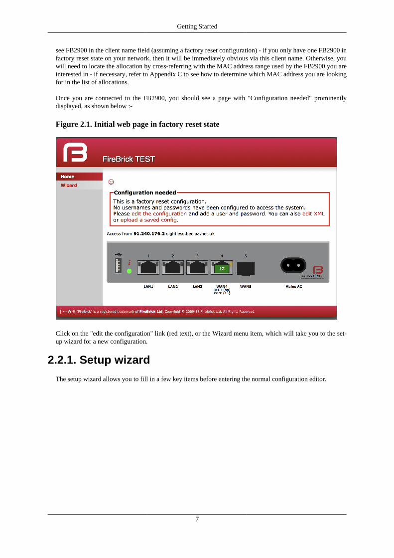
Getting Started
7
see FB2900 in the client name field (assuming a factory reset configuration) - if you only have one FB2900 infactory reset state on your network, then it will be immediately obvious via this client name. Otherwise, youwill need to locate the allocation by cross-referring with the MAC address range used by the FB2900 you areinterested in - if necessary, refer to Appendix C to see how to determine which MAC address you are lookingfor in the list of allocations.
Once you are connected to the FB2900, you should see a page with "Configuration needed" prominentlydisplayed, as shown below :-
Figure 2.1. Initial web page in factory reset state
Click on the "edit the configuration" link (red text), or the Wizard menu item, which will take you to the set-up wizard for a new configuration.
2.2.1. Setup wizard
The setup wizard allows you to fill in a few key items before entering the normal configuration editor.

Getting Started
8
Figure 2.2. Setup Wizard
There key settings may vary in later versions, but they represent the main settings you need to consider to getstarted.

Getting Started
9
2.2.1.1. Login username/password
The first part of the wizard covers your login to the FireBrick management interface. There are various waysthis access is controlled and locked down, but ultimately this is the way you control your configuration andso they are very important.
For simple security reasons it is better to pick a sensible username, and not admin
For good security reasons you should create a long, easy to remember, but hard to guess, password. There isno limit on how long you make the password, so you can create a complete pass phrase (i.e. a sentence) ifyou prefer. Rememver that upper/lower case matter as do spaces. The FireBrick does not make any attempt toenfoce password policy and will allow you to use a stupid password if you wish, just not a blank one.
Once you have finished the process for your initial config, and logged in, we strongly recommend setting up atwo factor authentication using a one time password app on a mobile phone, etc.
2.2.1.2. WAN/PPPoE settings
There are two main ways the FB2900 is connected to the Internet - either using a PPPoE device such as abridging modem or built in device such as an ADSL/VDSL SFP modem, or an external router that providesaccess via DHCP setting of a WAN address.
The wizard allows you to set these up, either or both, with PPPoE login/password on a port, and DHCP clienton a port, as a WAN interface.
NoteIf you use the wizard to make a WAN Ethernet port, you will no longer be able to access the webcontrol pages via that interface as it will not be considered local.
2.2.1.3. LAN settings
The factory default configuration provides a WAN and LAN. In the case of the LAN, several separate portsare configured as independant LAN subnets. The wizard allows you to define a LAN with one or more portsas a switched port group and define an IPv4 and IPv6 subnet that is used on that LAN. You can set a numberof options for DHCP, SLAAC, etc.
NoteTypically an ISP connection via PPPoE will Prefix Delegate IPv6 address blocks so these do notusually need to be set up manually.
2.2.1.4. Initial config
Having completed the initial wizard questions you will then find yourself in the normal cofiguration editor.You can make any more changes you need to the initial configuration, and then save this.
Once saved you are prompted to login using the username/password details you provided.
NoteThe wizard makes no attempt to check the details you entered, these simply become part of that initialconfiguration. As such you may see error messages when you try to save the config, and will need tomake corrections before you can proceed.
NoteIf you have changed the LAN IP address settings and are using DHCP on your connected computeryou may find you need to get a new address and re-connect to the FireBrick control pages at this point.

10
Chapter 3. Configuration3.1. The Object Hierarchy
The FB2900 has, at its core, a configuration based on a hierarchy of objects, with each object having one ormore attributes. An object has a type, which determines its role in the operation of the FB2900. The valuesof the attributes determine how that object affects operation. Attributes also have a type (or datatype), whichdefines the type of data that attribute specifies. This in turn defines what the valid syntax is for a value of thatdatatype - for example some are numeric, some are free-form strings, others are strings with a specific format,such as a dotted-quad IP address. Some examples of attribute values are :-
• IP addresses, and subnet definitions in CIDR format e.g. 192.168.10.0/24
• free-form descriptive text strings, e.g. a name for a firewall rule
• Layer 4 protocol port numbers e.g. TCP ports
• data rates used to control traffic shaping
• enumerated values used to control a feature e.g. defining Ethernet port LED functions
The object hierarchy can be likened to a family-tree, with relationships between objects referred to using termssuch as Parent, Child, Sibling, Ancestor and Descendant. This tree-like structure is used to :-
• group a set of related objects, such as a set of firewall rules - the parent object acts as a container for a groupof (child) objects, and may also contribute to defining the detailed behaviour of the group
• define a context for an object - for example, an object used to define a locally-attached subnet is a child ofan object that defines an interface, and as such defines that the subnet is accessible on that specific interface.Since multiple interfaces can exist, other interface objects establish different contexts for subnet objects.
Additional inter-object associations are established via attribute values that reference other objects, typicallyby name, e.g. a firewall rule can specify one of several destinations for log information to be sent when therule is processed.
3.2. The Object ModelThe term 'object model' is used here to collectively refer to :-
• the constraints that define a valid object hiearchy - i.e. which object(s) are valid child objects for a givenparent object, how many siblings of the same type can exist etc.
• for each object type, the allowable set of attributes, whether the attributes are mandatory or optional, theirdatatypes, and permissible values of those attributes
The bulk of this User Manual therefore serves to document the object model and how it controls operation ofthe FB2900.
Tip
This version of the User Manual may not yet be complete in its coverage of the full object model.Some more obscure attributes may not be covered at all - some of these may be attributes that arenot used under any normal circumstances, and used only under guidance by support personnel. If youencounter attribute(s) that are not documented in this manual, please refer in the first instance to thedocumentation described in Section 3.2.1 below. If that information doesn't help you, and you think

Configuration
11
the attribute(s) may be relevant to implementing your requirements, please consult the usual supportchannel(s) for advice.
3.2.1. Formal definition of the object modelThe object model has a formal definition in the form of an XML Schema Document (XSD) file, which isitself an XML file, normally intended for machine-processing. A more readable version of this information isavailable in Appendix M.
Note, however, that this is reference material, containing only brief descriptions, and intended for users whoare familiar with the product, and in particular, for users configuring their units primarily via XML.
The XSD file is also available on the software downloads website by following the "XSD" link that is presentagainst each software release.
3.2.2. Common attributesMost objects have a comment attribute which is free-form text that can be used for any purpose. Similarly,most objects have a source attribute that is intended for use by automated configuration management tools.Neither of these attributes have a direct effect on the operation of the FB2900.
Many objects have a name attribute which is non optional and often needs to be unique within the list of object.This allows the named object to be referenced from other attributes. The data type for these is typically anNMTOKEN which is a variant of a string type that does not allow spaces. If you include spaces then they areremoved automatically. This helps avoid any problems referencing names in other places especially where thereference may be a space separated list.
Many objects have a graph attribute. This allows a graph name to be specified. However, the actual graphname will be normalised to avoid spaces and limit the number of characters. Try to keep graph names as basiccharacters (letters, numbers) to avoid confusion.
3.3. Configuration MethodsThe configuration objects are created and manipulated by the user via one of two configuration methods :
• web-based graphical User Interface accessed using a standard web-browser (uses javascript).
• an XML (eXtensible Markup Language) file representing the entire object hierarchy, editable via the webinterface or can be uploaded to the FB2900
The two methods operate on the same underlying object model, and so it is possible to readily move betweenthe two methods - changes made via the User Interface will be visible as changes to the XML, and vice-versa.Which method you use is entirely up to you, and some users prefer one or the other, or may make some changesin one of the other. Some operations, such as changing the order of a list of objects, is easier in the XML editor,for example. The web based editor means you do not have to find/remember the attribite names as they are allpresented to you. For more information on using XML, refer to Section 3.6.
3.4. Data typesAll of the actual values in the configuration are provided by means of XML attributes, and so they arerepresented as a string of characters. The value is escaped as per XML rules, e.g. & for &, < for <,> for > and " for " within the string between the quote marks for the attribite value.
Obviously, even though all data is just a string, there are actually different data types, as defined in Section M.4,some of which have value restrictions (range of numbers, or specific string lengths, etc). Some of these aredescribed in more details here.

Configuration
12
3.4.1. Sending and receiving values
When you send the FireBrick a configuration the value is parsed and stored internally in a binary format. Thismeans that when you access the config later it is possible the value you see is a normalised version of the value.For example storing a number as 000123 will return as 123.
In some cases you can enter a value in a format you will never see come back when you view the config. Forexample, simple integers can have SI magnitide suffixes, e.g. G (giga), M (mega), or k (kilo), so you can enter1.5k but will see 1500. You can also use Gi (gibi), Mi (mebi), or Ki (kibi) for IEC units based on powersof two. You can also suffix B to mean bytes and the resulting value stored will be 8 times larger (as integersare used for bits/second speed settings). Other examples include using colour names like red which you seeas #ff0000.
3.4.2. Lists of values
Where the type is in fact a list of a type, the actual value in the XML attribute is actually a space separated list.This is consistent with the XSD (XML Schema Definition). In the web based editor such lists are automaticallysplit on to separate lines to make it easier to read and edit, but in the raw XML the list simple uses a singlespace between each item.
For example allow="192.168.0.0/16 10.0.0.0/8 172.16.0.0/12" lists there IP prefixes toallow.
3.4.3. Set of possible values
Some types are simply a set of acceptable values, the simplest of which is Boolean allowing false and true.
The simple lists of values are detailed in Section M.2, with the acceptable values.
However, in some cases a data type is a reference to some other object, in which case the acceptable values arethe name of those referenced objects. In most cases the web based config can ensure it provides a pull downmenu of the acceptable values.
There is one special case for IP groups where the value can be an IP address, or range, or the name of an IPgroup. In this case the web config editor expects you to correctly type the name of an IP group.
There is one other special case of graph names where you can typically enter any name, including one of thedefined shaper names or make up a new name as you wish with no error when you save the config. Graphs arecreated on the fly and so you have to be careful to correctly type graph names in the config to get the desiredeffect.
3.4.4. Dates, times, and durations
As per normal XML Schema rules, dates and times are in ISO8601 format, e.g. 2018-04-28 or2018-04-28T16L37:48.
However, unlike XML Schema rules, durations are in the format for HH:MM:SS, or MM:SS, or just seconds,e.g. 1:00:00 for one hour. However, to allow XML Schema compliant input a duration can also be enteredin the normal format such as PT1H for one hour, which appears as 1:00:00.
3.4.5. Colours
Colours can be entered in normal css style format such as #FF0000 or #F00, or use a small set of colournames such as red. A fourth byte for transparency can be provided if applicable.

Configuration
13
3.4.6. Passwords and secretsThere are two cases where the information entered in the config may be sensitive. One case is apassword, for example one used for a user login to the FireBrick. This this case you can providea simple text password in the config you send, but what you get back will be a hash, e.g.SHA256#92E12F9A333C68690078AC041CD840996EB366A190F7D8966C48AB84A5729F66DCBC7C1A019FC277583684E81015EA.The exact format used may change over time, and if an older hash, such as MD5 exists in the config, it willactually change to a newer hash format automatically next time someone logs in using that password. Thehashes include salt to make them harder to crask, but none the less it is best to keep config files secure andnot reveal the hashes used.
Another special case is the use of a OTP (One Time Passcode) system. You can put a plain text password anda BASE32 OTP seed in the config for a user, and they will come back as a hashed password (as above), anda # followed by base64 coded data for the OTP code.
In addition, there are also secrets which are passwords which cannot be stored in a hashed format (because ofthe way they are used). Both passwords and secrets are only displayed if you have full access to the config. Ifyou have limited access, or select to view the config with secrets hidden then they all appear as "secret".However such secrets are stored in the config file in plain text.
It is possible (though complex) for you to make hashes and OTP seeds off-line and simply store in the config.For more information on how passwords are hashed and OTP seeds are stored, see Appendix L.
3.4.7. IP addressesBeing an IP based firewall / router the FireBrick config has a lot of places where an IP address can be entered.In some cases a simple single IP address, but in some cases as an IP and subnet size (CIDR notation) or evena range of IP addresses. Often a list of IP addresses or ranges can be specified 9space separated list).
3.4.7.1. Simple IP addresses
Where a simple IP address is expected you can enter in any valid format for IP addresses. In some casesthe field may specifically be IPv4 or IPv6 but in most cases either type of IP address can be entered.In the case of IPv6, the :: shortened format is accepted, and used on output. The legacy format, e.g.2001:db8::192.168.0.1 format is also accepted as per IPv6 RFCs.
3.4.7.2. Subnets and prefixes
In some cases an IP address and subnet length is expected (in CIDR format), e.g. 192.168.0.1/24. Thereare two variations of this, one is a subnet which includes an IP address and length, such as 192.168.0.1/24.The other case is where the prefix is what matters, and so the IP address can be any within the prefix, so192.168.0.1/24 would actually read back as 192.168.0.0/24.
Where the subnet is one IP, e.g. 192.168.0.1/32 it can be provided as, and reads back as a simple IPaddress, i.e. 192.168.0.1.
3.4.7.3. Ranges
In some cases a range of IP addresses is needed, for example when making a filter for firewall rules or allow lists.
For IPv4 addresses this can use a format using a hyphen, e.g. 192.168.0.100-199. Where the rangeis wider there may be more after the hyphen, e.g. 192.168.0.100-1.99 is all from 192.168.0.100 to192.168.1.99. Ultimately it can be a complete range such as 10.1.2.3-11.100.2.5, though that is rarelyneeded.
Where a range covers all parts after the hyphen then an X can be used, e.g. 10.2-4.X.X for 10.2.0.0 to10.4.255.255.

Configuration
14
A range can be provided as a simple IP address (for one IP in range) or as a CIDR format. IPv6 addressranges can only be CIDR format prefixes. If a range happens to be a CIDR range it shows in that format. E.g.192.168.0.0-192.168.255.255 will read back as 192.168.0.0/16.
In some cases a list of IP ranges can also include named IP groups. In which case the IP groups are checkedby name, firstly in the case of a rule-set where ip-group entries are specified, then system ip-groupentries, and then named subnet entries (including DHCP client subnets).
3.4.7.4. Prefix filters
In somes cases a filter needs to be specified to allow a set of prefixes to be defined, such as BGP filters.
In this case the format has a range of prefix lengths using a hyphen, e.g. 10.0.0.0/8-24. The prefix mustmatch at least the lower size bits (/8 in that example), but can be any size in the range. Where the formatuses either end of the range it can be omitted either side of the hyphen, e.g. 10.0.0.0/8- is the same as10.0.0.0/8-32.
Some cases need to be more complex and a colon is used to add a third bit length, e.g. 10.0.0.0/8:16-24means all prefixes within 10.0.0.0/8 which are a prefix length of 16 to 24 bits, so that would include 10.1.0.0/17in that case.
3.5. Web User Interface OverviewThis section provides an overview of how to use the web-based User Interface. We recommend that youread this section if you are unfamiliar with the FB2900, so that you feel comfortable with the design of theUser Interface. Later chapters cover specific functionality topics, describing which objects are relevant, anyunderlying operational principles that are useful to understand, and what effect the attributes (and their values)have.
The web-based User Interface provides a method to create the objects that control operation of the FB2900.Internally, the User Interface uses a formal definition of the object model to determine where (in the hierarchy)objects may be created, and what attributes may exist on each object, so you can expect the User Interface toalways generate valid XML. 1
Additionally, the web User Interface provides access to the following items :-
• status information, such as DHCP server allocations, FB105 tunnel information and system logs
• network diagnostic tools, such as Ping and Traceroute ; there are also tools to test how the FB2900 willprocess particular traffic, allowing you to verify your firewalling is as intended
• traffic graphs
By default, access to the web user interface is available to all users, from any locally connected IP address. Ifyou don't require such open access, you may wish to restrict access using the settings described in Section 14.3.
3.5.1. User Interface layoutThe User Interface has the following general layout :-
• a 'banner' area at the top of the page, containing the FireBrick logo, model number and system name
• a main-menu, with sub-menus that access various parts of the user interface ; the main-menu can be shownvertically or horizontally - sub-menu appearance depends on this display style : if the main-menu is vertical,sub-menus are shown by 'expanding' the menu vertically ; if the main-menu is horizontal, sub-menus areshown as pull-down menus
1If the User Interface does not generate valid XML - i.e. when saving changes to the configuration the FireBrick reports XML errors, then thismay be a bug - please check this via the appropriate support channel(s).

Configuration
15
• a 'footer' area at the bottom of the page, containing layout-control icons and showing the current softwareversion
• the remaining page area contains the content for the selected part of the user-interface
Figure 3.1 shows the main menu when it is set to display horizontally. Note that the main-menu items themselveshave a specific function when clicked - clicking such items displays a general page related to that item - forexample, clicking on Status shows some overall status information, whereas sub-menu items under Statusdisplay specific categories of status information.
Figure 3.1. Main menu
The user interface pages used to change the device configuration are referred to as the 'config pages' in thismanual - these pages are accessed by clicking on the "Edit" item in the sub-menu under the "Config" main-menu item.
Note
The config pages utilise JavaScript for their main functionality ; you must therefore have JavaScriptenabled in your web browser in order to configure your FB2900 using the web interface.
3.5.1.1. Customising the layout
The following aspects of the user interface layout can be customised :-
• The banner area can be reduced in height, or removed all together
• The main menu strip can be positioned vertically at the left or right-hand sides, or horizontally at the top(under the banner, if present)
Additionally, you can choose to use the default fonts that are defined in your browser setup, or use the fontsspecified by the user interface.
These customisations are controlled using three icons on the left-hand side of the page footer, as shown inFigure 3.2 below :-
Figure 3.2. Icons for layout controls
The first icon, an up/down arrow, controls the banner size/visibility and cycles through three settings : full sizebanner, reduced height banner, no banner. The next icon, a left/right arrow, controls the menu strip positionand cycles through three settings : menu on the left, menu on the right, menu at the top. The last icon, the letter'A', toggles between using browser-specified or user-interface-specified fonts.
Layout settings are stored in a cookie - since cookies are stored on your computer, and are associated withthe DNS name or IP address used to browse to the FB2900, this means that settings that apply to a particularFB2900 will automatically be recalled next time you use the same computer/browser to connect to that FB2900.
It is also possible to configure an external CSS to use with the FireBrick web control pages which allows a greatdeal of control over the overall layout and appearance. This can be usful for dealers or IT support companiesto set up FireBricks in a style and branding of their choice.
3.5.2. Config pages and the object hierarchy

Configuration
16
The structure of the config pages mirrors the object hierachy, and therefore they are themselves naturallyhierachical. Your postition in the hierachy is illustrated in the 'breadcrumbs' trail at the top of the page, forexample :-
Firewall/mapping rules :: rule-set 1 of 3 (filters) :: rule 7 of 19 (ICMP)
This shows that the current page is showing a rule, which exists within a rule-set, which in turn is in the"Firewall/mapping rules" category (see below).
3.5.2.1. Configuration categories
Configuration objects are grouped into a number of categories. At the top of the config pages is a set of icons,one for each category, as shown in Figure 3.3 :-
Figure 3.3. Icons for configuration categories
Within each category, there are one or more sections delimited by horizontal lines. Each of these sections has aheading, and corresponds to a particular type of top-level object, and relates to a major part of the configurationthat comes under the selected category. See Figure 3.4 for an example showing part of the "Setup" category,which includes general system settings (the system object) and control of system services (network servicesprovided by the FB2900, such as the web-interface web server, telnet server etc., controlled by the servicesobject).
Figure 3.4. The "Setup" category
Each section is displayed as a tabulated list showing any existing objects of the associated type. Each row ofthe table corresponds with one object, and a subset (typically those of most interest at a glance) of the object'sattributes are shown in the columns - the column heading shows the attribute name. If no objects of that typeexist, there will be a single row with an "Add" link. Where the order of the objects matter, there will be an 'Add'link against each object - clicking an 'Add' link for a particular object will insert a new object before it. To adda new object after the last existing one, click on the 'Add' link on the bottom (or only) row of the table.

Configuration
17
Tip
If there is no 'Add' link present, then this means there can only exist a limited number of objects ofthat type (possibly only one), and this many already exist. The existing object(s) may have originatedfrom the factory reset configuration.
You can 'push-down' into the hierarchy by clicking the 'Edit' link in a table row. This takes you to a pageto edit that specific object. The page also shows any child objects of the object being edited, using the samehorizontal-line delimited section style used in the top-level categories. You can navigate back up the hierarchyusing various methods - see Section 3.5.3.
CautionClicking the "Add" link will create a new sub-object which will have blank/default settings. This canbe useful to see what attributes an object can take, but if you do not want this blank object to be partof the configuration you later save you will need to click Erase. Simply going back "Up" or moving toanother part of the config will leave this newly created empty object and that could have undesirableeffects on the operation of your FireBrick if saved.
3.5.2.2. Object settings
The details of an object are displayed as a matrix of boxes (giving the appearance of a wall of bricks), onefor each attribute associated with that object type. Figure 3.5 shows an example for an interface object(covered in Chapter 6) :-
Figure 3.5. Editing an "Interface" object
By default, more advanced or less frequently used attributes are hidden - if this applies to the object beingedited, you will see the text shown in Figure 3.6. The hidden attributes can be displayed by clicking on thelink "Show all".
Figure 3.6. Show hidden attributes
Each brick in the wall contains the following :-
• a checkbox - if the checkbox is checked, an appropriate value entry widget is displayed, otherwise, a defaultvalue is shown and applied for that setting. If the attribute is not optional then no checkbox is show.
• the attribute name - this is a compact string that exactly matches the underlying XML attribute name
• a short description of the attribute

Configuration
18
TipIf there is no default shown for an attribute then its value, if needed, is zero, blank, null, empty string,false (internally it is zero bits!). In some cases the presence of an attribute will have meaning evenif that attribute is an empty string or zero value. In some cases the default for an attribute will notbe a fixed value but will depend on other factors, e.g. it may be "auto", or "set if using xyz...". Thedescription of the default value should make this clear. Where an optional attribute is not ticked theattribute does not appear in the XML at all.
These can be seen in Figure 3.7 :-
Figure 3.7. Attribute definitions
If the attribute value is shown in a 'strike-through' font (with a horizontal line through it mid-way vertically),this illustrates that the attribute can't be set - this will happen where the attribute value would reference aninstance of particular type of object, but there are not currently any instances of objects of that type defined.
Tip
Since the attribute name is a compact, concise and un-ambiguous way of referring to an attribute, pleasequote attribute names when requesting technical support, and expect technical support staff to discussyour configuration primarily in terms of attribute (and object/element) names, rather than descriptivetext, or physical location on your screen (both of which can vary between software releases).
3.5.3. Navigating around the User InterfaceYou navigate around the hierarchy using one or more of the following :-
• configuration category icons
• the breadcrumbs - each part of the breadcrumbs (delimited by the :: symbol) is a clickable link
• the in-page navigation buttons, shown in Figure 3.8 : "Up" - move one level up in the object hierachy, "Prev"- Previous object in a list, and "Next" - Next object in a list.
Figure 3.8. Navigation controls
Caution
The configuration pages are generated on-the-fly using JavaScript within your web browserenvironment (i.e. client-side scripting). As such, the browser is essentially unaware of changes to

Configuration
19
page content, and cannot track these changes - this means the browser's navigation buttons (Back,Forward), will not correctly navigate through a series of configuration pages.
Please take care not to use the browser's Back button whilst working through configuration pages -navigation between such pages must be done via the buttons provided on the page - "Prev", "Next"and "Up".
Navigating away from an object using the supported navigation controls doesn't cause any modifications tothat object to be lost, even if the configuration has not yet been saved back to the FB2900. All changes areinitially held in-memory (in the web browser itself), and are committed back to the FireBrick only when youpress the Save button.
The navigation button area, shown in Figure 3.8, also includes three other buttons :-
• New : creates a new instance of the object type being edited - the new object is inserted after the current one ;this is equivalent to using the "Add" link one level up in the hierarchy
• Erase : deletes the object being edited - note that the object will not actually be erased until the configurationis saved
• Help : browses to the online reference material (as desribed in Section 3.2.1) for the object type being edited
Caution
If you Add a new object, but don't fill in any parameter values, the object will remain in existenceshould you navigate away. You should be careful that you don't inadvertently add incompletely setupobjects this way, as they may affect operation of the FireBrick, possibly with a detrimental effect.
If you have added an object, perhaps for the purposes of looking at what attributes can be set on it,remember to delete the object before you navigate away -- the "Erase" button (see Figure 3.8) is usedto delete the object you are viewing.
3.5.4. Backing up / restoring the configurationTo back up / save or restore the configuration, start by clicking on the "Config" main-menu item. This willshow a page with a form to upload a configuration file (in XML) to the FB2900 - also on the page is a link"Download/save config" that will download the current configuration in XML format.
3.6. Configuration using XML
3.6.1. Introduction to XMLAn XML file is a text file (i.e. contains human-readable characters only) with formally defined structure andcontent. An XML file starts with the line :-
<?xml version="1.0" encoding="UTF-8"?>
This defines the version of XML that the file complies with and the character encoding in use. The UTF-8character coding is used everywhere by the FireBrick.
The XML file contains one or more elements, which may be nested into a hiearchy.
Note
In XML, the configuration objects are represented by elements, so the terms object and element areused interchangeably in this manual.
Each element consists of some optional content, bounded by two tags - a start tag AND an end tag.
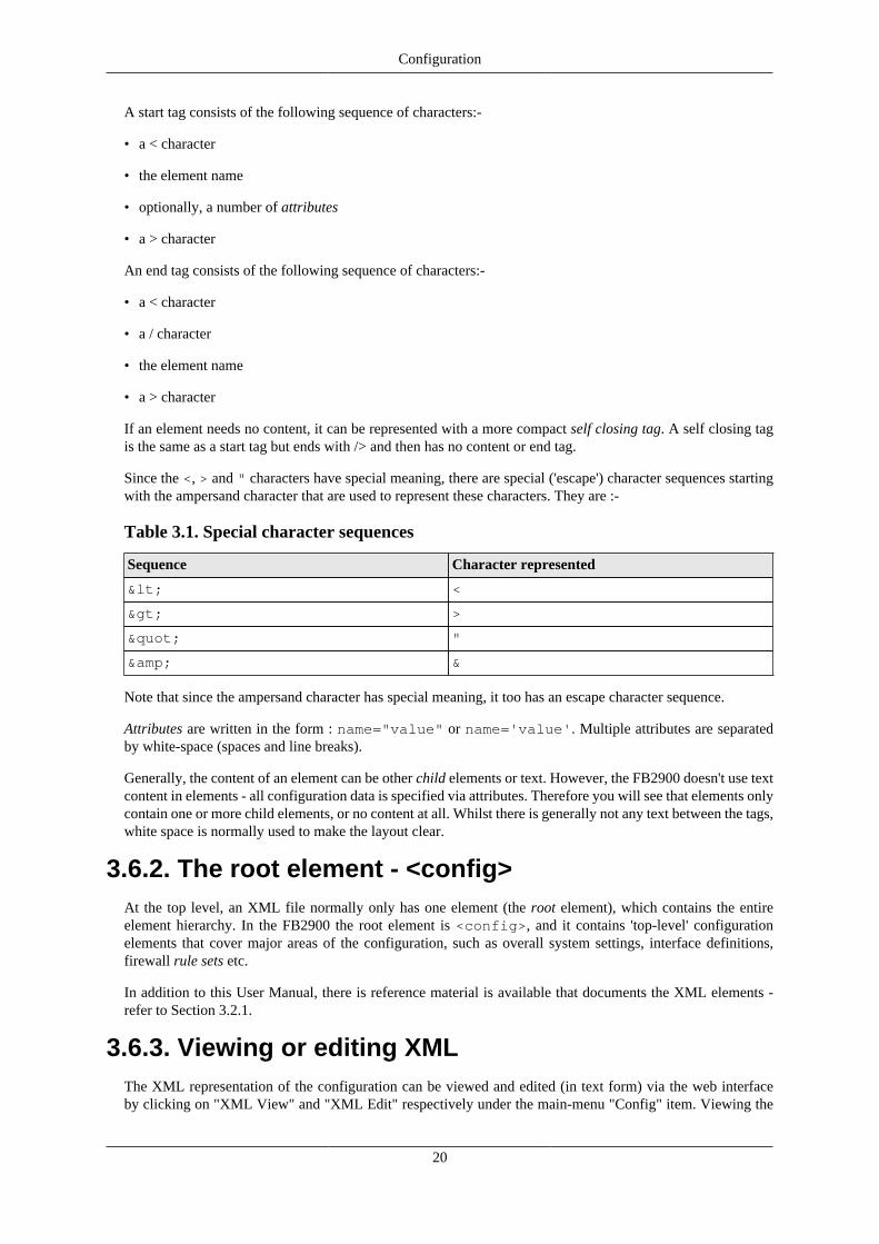
Configuration
20
A start tag consists of the following sequence of characters:-
• a < character
• the element name
• optionally, a number of attributes
• a > character
An end tag consists of the following sequence of characters:-
• a < character
• a / character
• the element name
• a > character
If an element needs no content, it can be represented with a more compact self closing tag. A self closing tagis the same as a start tag but ends with /> and then has no content or end tag.
Since the <, > and " characters have special meaning, there are special ('escape') character sequences startingwith the ampersand character that are used to represent these characters. They are :-
Table 3.1. Special character sequences
Sequence Character represented
< <
> >
" "
& &
Note that since the ampersand character has special meaning, it too has an escape character sequence.
Attributes are written in the form : name="value" or name='value'. Multiple attributes are separatedby white-space (spaces and line breaks).
Generally, the content of an element can be other child elements or text. However, the FB2900 doesn't use textcontent in elements - all configuration data is specified via attributes. Therefore you will see that elements onlycontain one or more child elements, or no content at all. Whilst there is generally not any text between the tags,white space is normally used to make the layout clear.
3.6.2. The root element - <config>At the top level, an XML file normally only has one element (the root element), which contains the entireelement hierarchy. In the FB2900 the root element is <config>, and it contains 'top-level' configurationelements that cover major areas of the configuration, such as overall system settings, interface definitions,firewall rule sets etc.
In addition to this User Manual, there is reference material is available that documents the XML elements -refer to Section 3.2.1.
3.6.3. Viewing or editing XMLThe XML representation of the configuration can be viewed and edited (in text form) via the web interfaceby clicking on "XML View" and "XML Edit" respectively under the main-menu "Config" item. Viewing the

Configuration
21
configuration is, as you might expect, 'read-only', and so is 'safe' in as much as you can't accidentally changethe configuration.
3.6.4. Example XML configurationAn example of a simple, but complete XML configuration is shown below, with annotations pointing out themain elements
<?xml version="1.0" encoding="UTF-8"?><config xmlns="http://firebrick.ltd.uk/xml/fb2700/" xmlns:xsi="http://www.w3.org/2001/XMLSchema-instance" xsi:schemaLocation="http://firebrick.ltd.uk/xml/fb2700/ ... timestamp="2011-10-14T12:24:07Z" patch="8882">
<system name="gateway" contact="Peter Smith" location="The Basement" log-panic="fb-support"> </system>
<user name="peter" full-name="Peter Smith" password="FB105#4D42454D26F8BF5480F07DFA1E41AE47410154F6" timeout="PT3H20M" config="full" level="DEBUG"/>
<log name="default"/> <log name="fb-support"> <email to="[email protected]" comment="Crash logs emailed to FireBrick Support"/> </log>
<services> <ntp timeserver="pool.ntp.org"/> <telnet log="default"/> <http /> <dns domain="watchfront.co.uk" resolvers="81.187.42.42 81.187.96.96"/> </services>
<port name="WAN" ports="1"/> <port name="LAN" ports="2"/>
<interface name="WAN" port="WAN"> <subnet name="ADSL" ip="81.187.106.73/30"/> </interface>
<interface name="LAN" port="LAN">

Configuration
22
<subnet name="LAN" ip="81.187.96.94/28"/> <dhcp name="LAN" ip="81.187.96.88-92" log="default"/> </interface>
<rule-set name="filters" no-match-action="drop"> <rule name="Our-Traffic" source-interface="self" comment="FB originated traffic allowed"/> <rule name="FireBrick UI" target-port="80" target-interface="self" protocol="6"/> <rule name="ICMP" protocol="1" log="default"/> <rule name="All outgoing" source-interface="LAN"/> <rule name="FB-access" source-interface="LAN" target-port="80" target-interface="self" protocol="6" comment="FB web config access"/> <rule name="final-no-match" log="default" action="drop" comment="Catch all - sets default logging for no match"/> </rule-set> </config>
Top level attributes are effectively read only as they are overwritten when a config is uploaded. Theseare for your information, and include things like the date/time the config was uploaded, and the usernameand IP address that uploaded the config, etc.sets some general system parameters (see Section 4.2)defines a single user with the highest level of access (DEBUG) (see Section 4.1)defines a log target (see Chapter 5)configures key system services (see Chapter 14)defines physical-port group (see Section 6.1)defines an interface, with one subnet and a DHCP allocation pool (see Chapter 6)defines a set of firewalling rules (see Chapter 7)
3.7. Downloading/Uploading theconfiguration
The XML file may be retrieved from the FireBrick, or uploaded to the FireBrick using HTTP transfers donevia tools such as curl. Using these methods, configuration of the FB2900 can be integrated with existingadministrative systems.

Configuration
23
Note
Linebreaks are shown in the examples below for clarity only - they must not be entered on thecommand-line
3.7.1. DownloadTo download the configuration from the FB2900 you need to perform an HTTP GET of the following URL :-
http://<FB2900 IP address or DNS name>/config/config
An example of doing this using curl, run on a Linux box is shown below :-
curl http://<FB2900 IP address or DNS name>/config/config --user "username:password" --output "filename"
Replace username and password with appropriate credentials.
The XML configuration file will be stored in the file specified by filename - you can choose any file extensionyou wish (or none at all), but we suggest that you use .xml for consistency with the file extension used whensaving a configuration via the User Interface (see Section 3.5.4).
NoteWhen fetching the config in this was the initial config attributes will include formal namespace and xsischemalocation attributes. These are not normally shown on the config editor via the web interface,and are ignored when uploading a config.
3.7.2. UploadTo upload the configuration to the FB2900 you need to send the configuration XML file as if posted by a webform, using encoding MIME type multi-part/form-data.
An example of doing this using curl, run on a Linux box is shown below :-
curl http://<FB2900 IP address or DNS name>/config/config --user "username:password" --form config="@filename"
Note
You can also include --form override=true to force the config to be loaded even if it hasminor (recoverable) errors, e.g. if it is config for older version of FireBrick.

24
Chapter 4. System Administration4.1. User Management
You will have created your first user as part of the initial setup of your FB2900, as detailed in either theQuickStart Guide or in Chapter 2 in this manual.
To create, edit or delete users, browse to the config pages by clicking the "Edit" item in the sub-menu underthe "Config" main-menu item, then click on the "Users" category icon. Click on the "Edit" link adjacent to theuser you wish to edit, or click on the "Add" link to add a user.
To delete a user, click the appropriate "Edit" link, then click the "Erase" button in the navigation controls - seeFigure 3.8. As with any such object erase operation, the object will not actually be erased until the configurationis saved.
Once you have added a new user, or are editing an existing user, the object editing page will appear, as shownin Figure 4.1 :-
Figure 4.1. Setting up a new user
The minimum attributes that must be specified are name, which is the username that you type in when loggingin, and password - passwords are mandatory on the FB2900.
You can optionally provide a full name for the specified username, and a general comment field value.
4.1.1. Login levelA user's login level is set with the level attribute, and determines what CLI commands the user can run. Thedefault, if the level attribute is not specified, is ADMIN - you may wish to downgrade the level for users whoare not classed as 'system administrators'.

System Administration
25
Table 4.1. User login levels
Level Description
NOBODY No access to any menu items, but can access controlswitches for which the user has access.
GUEST Guest user, access to some menu items
USER Normal unprivileged user
ADMIN System administrator
DEBUG System debugging user
TipIn general you only want to use NOBODY, ADMIN or DEBUG levels.
4.1.2. Configuration access levelThe configuration access level determines whether a user has read-only or read-write access to theconfiguration, as shown in Table 4.2 below. This mechanism can also be used to deny all access to theconfiguration using the none level, but still allowing access to other menus and diagnostics.
This setting is distinct from, and not connected with, the login level described above. You can use the accesslevel to define, for example, whether a USER login-level user can modify the configuration. Typically anADMIN (or DEBUG) login-level user would always be granted full access, so for ADMIN or DEBUG leveluser's, the default of full is suitable.
Table 4.2. Configuration access levels
Level Description
none No access unless explicitly listed
view View only access (no passwords or hashes)
read Read only access (with passwords and hashes)
full Full view and edit access - DEFAULT
4.1.3. Login idle timeoutTo improve security, login sessions to either the web user interface, or to the command-line interface (via telnet,see Chapter 21), will time-out after a period of inactivity. This idle time-out defaults to 5 minutes, and can bechanged by setting the timeout attribute value.
The time-out value is specified using the syntax for the XML fb:duration data type. The syntax is hours, minutesand seconds, or minutes and seconds or just seconds. E.g. 5:00.
To set a user's time-out in the user interface, tick the checkbox next to timeout, and enter a value in theformat described above.
Setting a timeout to 0 means unlimited and shoudl obviously be used with care.
4.1.4. Restricting user logins
4.1.4.1. Restrict by IP address
You can restrict logins by a given user to be allowed only from specific IP addresses, using the allow attribute.This restriction is per-user, and is distinct from, and applies in addition to, any restrictions specified on either the

System Administration
26
web or telnet (for command line interface access) services (see Section 14.3 and Section 14.4), or any firewallrules that affect web or telnet access to the FB2900 itself.
4.1.4.2. Logged in IP address
The FireBrick allows a general definition of IP groups which allow a name to be used in place of a range ofIP addresses. This is a very general mechanism that can be used for single IP addresses or groups of rangesIPs, e.g. admin-machines may be a list or range of the IP addresses from which you want to allow some access.The feature can also be useful even where only one IP is in the group just to give the IP a meaningful namein an access list.
These named IP groups can be used in the allow list for a user login, along with specific IP addresses or rangesif needed.
However, IP groups can also list one or more user names and implicitely include the current IP address fromwhich those users are logged in to the web interface. This can be useful for firewall rules where you may haveto log in to the FireBrick, even as a NOBODY level user, just to get your IP address in an access list to allowfurther access to a network from that IP.
4.1.4.3. Restrict by profile
By specifying a profile name using the profile attribute, you can allow logins by the user only when theprofile is in the Active state (see Chapter 9). You can use this to, for example, restrict logins to be allowedonly during certain times of the day, or you can effectively suspend a user account by specifying an always-Inactive profile.
4.1.5. Password changeNormally, all config data is updated via the config edit process, and this allows a new password to be set forany user.
However, there is also a menu to allow a logged in user to change their own password. This does not requirethe user to have any config access permission. Simply enter the old password, and the new password twiceand the password is updated.
If you have OTP set up on a user, then you cannot change the password simply using the configuration editor(unless also setting a new OTP from scratch or removing the OTP). In such cases the password should be setusing the password change web page. This is also good practice is it avoids the administrator knowing people'spasswords.
4.1.6. One Time Password (OTP)A login to the FireBrick normally requires only a username and password. However you can configue anadditional security measure using a One Time Password (OTP) device. These are available as key fobs thatshow a code, but are more commonly done by use of a mobile phone application.
In order for the device to work you need a key which is known to the FireBrick and the device. However, thisis very simple to set up. A user can access the Password / OTP menu where a random key is allocated anddisplayed within a QR 2D bar code. Most authenticator applications simply scan the QR code and start showingthe 6 digit number on the display (which changes every 30 seconds). You then enter your password and a codefrom your device and you are set up.
It is possible for anyone with configuration access to edit your user settings and remove the OTP settings if youwish. This can be useful if you lose or break the phone, for example. You may want to keep a local configurationuser as a backup as well, as OTP cannot be used if the clock is not set for any reason.
When you login, after you submit your username and password you are asked for a code from the authenticatorto complete the login process.

System Administration
27
It is also possible to enter the password as the authenticator code followed by the configured password. This isuseful if using http authentication to access a web page where there is no separate option for the authentictorinput to be provided.
If OTP is configured you can leave the password blank (which is not normally allowed) and hence use theauthenticator code as the entire password, though this is not recommended for secuiry reasons as it also meansthe TOTP seed is recoverable from the config..
NoteTechnical details to allow you to create configs with password and OTP seed hashes are describedin Appendix L.
4.2. General System settingsThe system top-level object can specify attributes that control general, global system settings. The availableattributes are described in the following sections, and can be configured in the User Interface by choosing the"Setup" category, then clicking the "Edit" link under the heading "System settings".
The software auto upgrade process is controlled by system objects attributes - these are described inSection 4.3.3.2.
4.2.1. System name (hostname)The system name, also called the hostname, is used in various aspects of the FB2900's functions, and so werecommend you set the hostname to something appropriate for your network.
The hostname is set using the name attribute.
4.2.2. Administrative detailsThe attributes shown in Table 4.3 allow you to specify general administrative details about the unit :-
Table 4.3. General administrative details attributes
Attribute Purpose
comment General comment field
contact Contact name
intro Text that appears on the 'home' page - the home pageis the first page you see after logging in to the FB2900.This text is also displayed immediately after you loginto a command-line session.
location Physical location description
4.2.3. System-level event logging controlThe log and log-... attributes control logging of events related to the operation of the system itself. Fordetails on event logging, please refer to Chapter 5, and for details on the logging control attributes on systemobject, please refer to Section 5.7.
4.2.4. Home page web linksThe home page is the first page you see after logging in to the FB2900, or when you click the Home main-menu item. The home page displays the system name, and, if defined, the text specified by the intro attributeon the system object.

System Administration
28
Additionally, you can define one or more web links to appear on the home page. These are defined using linkobjects, which are child objects of the system object.
To make a usable link, you must specify the following two attributes on the link object :-
• text : the text displayed as a hyperlink
• url : link destination URL
Additionally, you can name a link, specify a comment, and make the presence of the link on the home pageconditional on a profile.
4.3. Software UpgradesFB2900 users benefit from FireBrick's pro-active software development process, which delivers fast fixes ofimportant bugs, and implementation of many customer enhancement requests and suggestions for improvement.As a matter of policy, FireBrick software upgrades are always free to download for all FireBrick customers.
To complement the responsive UK-based development process, the FB2900 is capable of downloading andinstalling new software directly from Firebrick's servers, providing the unit has Internet access.
This Internet-based upgrade process can be initiated manually (refer to Section 4.3.3.1), or the FB2900 candownload and install new software automatically, without user intervention.
If the unit you want to upgrade does not have Internet access, then new software can be uploaded to the unitvia a web browser instead - see Section 4.3.4.
Caution
Software upgrades are best done using the Internet-based upgrade process if possible - this ensuresthe changes introduced by Breakpoint releases are automatically accounted for (see Section 4.3.1.1)
Software upgrades will trigger an automatic reboot of your FB2900 - this will cause an outage in routing,and can cause connections that are using NAT to drop. However, the FB2900 reboots very quickly, and inmany cases, users will be generally unaware of the event. You can also use a profile to restrict when softwareupgrades may occur - for example, you could ensure they are always done over night. The reboot will closeall L2TP connections first. The reboot will close all BGP sessions first. The reboot will wait for all VoIP callsto complete before rebooting.
4.3.1. Software release typesThere are three types of software release : factory, beta and alpha. For full details on the differencesbetween these software releases, refer to the FB2900 software downloads website [http://www.firebrick.co.uk/software.php?PRODUCT=2900] - please follow the 'read the instructions' link that you will find just abovethe list of software versions.
Note
In order to be able to run alpha releases, your FB2900 must be enabled to run alpha software - thisis done by changing the entry in the FireBrick capabilities database (hosted on FireBrick companyservers) for your specific FB2900, as identified by the unit's Serial Number. Normally your FB2900will be running factory or possibly beta software, with alpha software only used under advice andguidance of support personnel while investigating/fixing possible bugs or performance issues. Youcan see whether your FB2900 is able to run alpha releases by viewing the main Status page (click theStatus main menu-item), and look for the row labelled "Allowed" - if the text shows "Alpha builds(for testing)" then your FB2900 can run alpha releases.
4.3.1.1. Breakpoint releases

System Administration
29
Occasionally, a software release will introduce a change to the object model that means the way specificfunctionality is configured in XML also changes - for example an attribute may have been deprecated, anda replacement attribute should be used instead. A release where such an change has been made, and existingconfigurations will need modifying, are termed Breakpoint software releases.
Breakpoint releases are special as they are able to automatically update an existing configuration - used withthe previous software release - so that it is compatible with the new release, and functionality is retained where-ever possible.
When using the Internet-based upgrade process, the FB2900 will always upgrade to the next availablebreakpoint version first, so that the configuration is updated appropriately. If your current software version isseveral breakpoint releases behind the latest version, the upgrade process will be repeated for each breakpointrelease, and then to the latest version if that is later than the latest breakpoint release.
On the FB2900 software downloads website, breakpoint releases are labelled [Breakpoint] immediatelyunder the version number.
Note
If you have saved copies of configurations for back-up purposes, always re-save a copy after upgradingto a breakpoint issue. If you use automated methods to configure your FB2900, check documentationto see whether those methods need updating.
4.3.2. Identifying current software versionThe current software version is displayed on the main Status page, shown when you click the Status mainmenu-item itself (i.e. not a submenu item). The main software application version is shown next to the word"Software", e.g. :-
Software FB2901 TEST Ximenes+ (V1.45.069 2017-09-27T08:14:40))
The software version is also displayed in the right hand side of the 'footer' area of each web page, and is shownimmediately after you login to a command-line session.
4.3.3. Internet-based upgrade process
Note
'Out of the box' the FB2900 is configured to automatically download and install new factory releases.This is a safe option, and we expect many users to be happy with this - however, if you would prefer,this process can be disabled - refer to Section 4.3.3.2.
If automatic installs are allowed, the FB2900 will check for new software on boot up and approximately every24 hours thereafter - your FB2900 should therefore pick up new software at most ~ 24 hours after it is released.You can choose to allow this process to install only new factory-releases, factory or beta releases, or any release,which then includes alpha releases (if your FB2900 is enabled for alpha software - see Section 4.3.1) - refer toSection 4.3.3.2 for details on how to configure auto upgrades.
CautionAlpha releases may be unstable, and so we do not generally recommend setting your FB2900 toautomatically install alpha releases.
4.3.3.1. Manually initiating upgrades
Whenever you browse to the main Status page, the FB2900 checks whether there is newer software available,given the current software version in use, and whether alpha releases are allowed. If new software is available,you will be informed of this as shown in Figure 4.2 :-

System Administration
30
Figure 4.2. Software upgrade available notification
To see what new software is available, click on the "Upgrade available" link. This will take you to a page thatwill show Release notes that are applicable given your current software version, and the latest version available.On that page there is an "Upgrade" button which will begin the software upgrade process.
4.3.3.2. Controlling automatic software updates
There are two attributes on the system object (see Section 4.2) that affect the automatic software upgradeprocess :-
Table 4.4. Attributes controlling auto-upgrades
Attribute Description
sw-update Controls what types of software releases the auto-upgrade process will download/install. This attributecan also be used to disable the auto-upgrade process -use the value of false to achieve this.
• false : Disables auto upgrades
• factory : Only download/install factory releases- this is the default if the attribute is not specified
• beta : Download/install factory or beta releases
• alpha : Download/install factory, beta or alphareleases
sw-update-profile Specifies the name of a profile to use to control whensoftware upgrades are attempted (see Chapter 9 fordetails on profiles).
The current setting of sw-update (in descriptive form) can be seen on the main Status page, adjacent to theword "Upgrade", as shown in Figure 4.2 (in that example, sw-update is set to, or is defaulting to, factory).
4.3.4. Manual upgradeThis method is entirely manual, in the sense that the brick itself does not download new software from theFireBrick servers, and responsibilty for loading breakpoint releases as required lies with the user.
In order to do this, you will first need to download the required software image file (which has the fileextension .img) from the FB2900 software downloads website [http://www.firebrick.co.uk/software.php?PRODUCT=2900] onto your PC.
The next step is the same as you would perform when manually-initiating an Internet-based upgrade i.e. youshould browse to the main Status page, where, if there is new software is available, you will be informed ofthis as shown in Figure 4.2.
This step is necessary since the manual upgrade feature currently shares the page used for Internet-based manualupgrades, which is reached by clicking "Upgrade available" link. After clicking this link, you will find themanual upgrade method at the bottom of the page, as shown in Figure 4.3 :-

System Administration
31
Figure 4.3. Manual Software upload
4.4. Global LED controlThe FB2900 has a main status LED and port status LEDs on the panel housing the sockets, and mirror LEDswhich normally display the same information on the opposite panel. The main status LED can display anycolour specified using standard RGB values or colour names. Each of the RJ45 ports has an orange and greenLED on its left, and a yellow LED on its right.
The colour of the main status LED, and the brightness of all the LEDs can be controlled by system attributesas shown in Table 4.5:-
Table 4.5. Global LED control
Attribute Value
status-led-colour Hex RGB or known colour name (default green)
port-led-brightness Brightness specified as an integer percentage, range1..100 (default 100)
mirror-led-brightness Brightness specified as an integer percentage, range1..100 (default 100)
4.5. Boot ProcessThe FB2900 contains internal Flash memory storage that holds two types of software :-
• main application software (generally referred to as the app)
• a bootloader - runs immediately on power-up, initialises system, and then loads the app
It is possible for only one of these types of software, or neither of them, to be present in the Flash, but whenshipped from the factory the unit will contain a bootloader and the latest factory-release application software.The FB2900 can store multiple app software images in the Flash, and this is used with an automatic fall-backmechanism - if a new software image proves unreliable, it is 'demoted', and the unit falls back to running oldersoftware. The show flash contents CLI command can be used to see what is stored in the Flash - seeAppendix J.
4.5.1. LED indications
4.5.1.1. Status LED indications
The status LED has three defined states, as shown in Table 4.6 below :-
Table 4.6. Status LED indications
Indication Status
Off No power applied to unit (or possibly hardware fault)
Flashing with approximately 1 second period Bootloader running / waiting for network connection
On Main application software running

System Administration
32
After power-up, the normal LED indication sequence is therefore to go through the ~1 second period flashingphase, and then - if at least one Ethernet port is connected to an active device, or after a few seconds waitingfor a factory reset cable - change to solid once the app is running.
NoteThe status LED can be configured to be a different colour when the main application software isrunning, including black (i.e. off). The LED can also be set to different colours and cycle throughcolours based on active profiles (see Chapter 9).
From power-up, a FB2900 will normally boot and be operational in under five seconds.
4.5.1.2. Port LEDs
Whilst the bootloader is waiting for an active Ethernet connection, the green and yellow LEDs built into thephysical port connectors flash in a continual left-to-right then right-to-left sequence. The port LEDs on thepanel on the opposite side to the physical ports also flash, in a clockwise sequence.
Note
The same port LED flashing sequences are observed if the app is running and none of the Ethernetports are connected to an active link-partner. Note that the app continues to run, and the power/statusLED will still be on solid.
When connected to an active link-partner, these flashing sequences will stop and the port LEDs will startindicating physical port status, with various status indications possible, controllable via the configuration (seeSection 6.4).
NoteThe SFP port has no LEDs indicating status.

33
Chapter 5. Event Logging
5.1. OverviewMany events in the operation of the FireBrick create a log entry. These are a one-line string of text saying whathappened. This could be normal events such as someone logging in to the web interface, or unusual events suchas a wrong password used, or DHCP not being able to find any free addresses to allocate.
5.1.1. Log targetsA log target is a named destination (initially internal to the FB2900) for log entries - you can have multiple logtargets set up which you can use to separate out log event messages according to some criteria - for example,you could log all firewalling related log events to a log target specifically for that purpose. This makes it easierto locate events you are looking for, and helps you keep each log target uncluttered with un-related log events- this is particularly important when when you are logging a lot of things very quickly.
A log target is defined using a log top-level object - when using the web User Interface, these objects are inthe "Setup" category, under the heading "Log target controls".
Every log entry is put in a buffer in RAM, which only holds a certain number of log entries (typically around1MB of text) - once the buffer is full, the oldest entries are lost as new ones arrive. Since the buffer is storedin volatile memory (RAM), buffer contents are lost on reboot or power failure.
This buffer can be viewed via the web interface or command line which can show the history in the buffer andthen follow the log in real time (even when viewing via a web browser, with some exceptions - see Section 5.6.1).
In some cases it is essential to ensure logged events can be viewed even after a power failure. You can flag alog target to log to the non-volatile Flash memory within the FB2900, where it will remain stored even after apower failure. You should read Section 5.5 before deciding to log events to Flash memory.
Each log target has various attributes and child objects defining what happens to log entries to this target.However, in the simplest case, where you do not require non-volatile storage, or external logging (seeSection 5.3), the log object will only need a name attribute, and will have no child objects. In XML this willlook something like :-
<log name="my_log"/>
5.1.1.1. Logging to Flash memory
The internal Flash memory logging system is separate from the external logging. It applies if the log targetobject has flash="true". It causes each log entry to be written to the internal non-volatile Flash log asit is created.
The flash log is intended for urgent permanent system information only, and is visible using the show flashlog CLI command (see Appendix J for details on using this command). Chapter 21 covers the CLI in general.
Caution
Flash logging slows down the system considerably - only enable Flash logging where absolutelynecessary.
The flash log does have a limit on how much it can hold, but it is many thousands of entries so this is rarely anissue. Oldest entries are automatically discarded when there is no space.

Event Logging
34
5.1.1.2. Logging to the Console
The console is the command line environment described in Chapter 21. You can cause log entries to be displayedas soon as possible on the console (assuming an active console session) by setting console="true" onthe log target.
You can stop the console logging with troff command or restart it with tron command.
5.2. Enabling loggingEvent logging is enabled by setting one of the attributes shown in Table 5.1 on the appropriate object(s) in theconfiguration, which depends on what event(s) you are interested in. The attribute value specifies the nameof the log target to send the event message to. The events that cause a log entry will naturally depend on theobject on which you enable logging. Some objects have additional attributes such as log-error for unusualevents, and log-debug for extra detail.
Table 5.1. Logging attributes
Attribute Event types
log This is normal events. Note that if log-error is notset then this includes errors.
log-error This is when things happen that should not. It could besomething as simple as bad login on telnet. Note thatif log-error is not set but log is set then errors arelogged to the log target by default.
log-debug This is extra detail and is normally only used whendiagnosing a problem. Debug logging can be a lot ofinformation, for example, in some cases whole packetsare logged (e.g. PPP). It is generally best only to usedebug logging when needed.
5.3. Logging to external destinationsEntries in the buffer can also be sent on to external destinations, such as via email or syslog. Support fortriggering SNMP traps may be provided in a future software release.
You can set these differently for each log target. There is inevitably a slight lag between the event happeningand the log message being sent on, and in some cases, such as email, you can deliberately delay the sendingof logs to avoid getting an excessive number of emails.
If an external logging system cannot keep up with the rate logs are generated then log entries can be lost. Thefastest type of external logging is using syslog which should manage to keep up in pretty much all cases.
5.3.1. SyslogThe FB2900 supports sending of log entries across a network to a syslog server. Syslog is described in RFC5424[http://tools.ietf.org/html/rfc5424], and the FB2900 includes microsecond resolution time stamps, the hostname(from system settings) and a module name in entries sent via syslog. Syslog logging is very quick as thereis no reply, and syslog servers can be easily setup on most operating systems, particularly Unix-like systemssuch as Linux.
Note
Older syslog servers will typically show time and hostname twice, and will need upgrading.

Event Logging
35
The module name refers to which part of the system caused the log entry, and is also shown in all other typesof logging such as web and console.
To enable log messages to be sent to a syslog server, you need to create a syslog object that is a child of thelog target (log) object. You must then specify the DNS name or IP address of your syslog server by settingthe server attribute on the syslog object. You can also set the facility and/or severity values using theseattributes :-
• facility : the 'facility' to be used in the syslog messages - when syslog entries are generated by subsystemsor processes in a general-purpose operating system, the facility typically identifies the message source ;where the commonly used facility identifiers are not suitable, the "local0" thru "local7" identifiers can beused. If the facility attribute is not set, it defaults to LOCAL0
• severity : the severity value to be used in the syslog messages - if not set, the severity defaults to NOTICE
The FB2900 normally uses the 'standard' syslog port number of 514, but if necessary, you can change this bysetting the port attribute value.
5.3.2. EmailYou can cause logs to be sent by e-mail by creating an email object that is a child of the log target (log) object.
An important aspect of emailed logs is that they have a delay and a hold-off. The delay means that the emailis not sent immediately because often a cluster of events happen over a short period and it is sensible to waitfor several log lines for an event before e-mailing.
The hold-off period is the time that the FB2900 waits after sending an e-mail, before sending another. Havinga hold-off period means you don't get an excessive number of e-mails ; since the logging system is initiallystoring event messages in RAM, the e-mail that is sent after the hold-off period will contain any messages thatwere generated during the hold-off period.
The following aspects of the e-mail process can be configured :-
• subject : you can either specify the subject, by setting the subject attribute value, or you can allow theFB2900 to create a subject based on the first line of the log message
• e-mail addresses : as to be expected, you must specify a target e-mail address, using the to attribute. Youcan optionally specify a From: address, by setting the from atttribute, or you can allow the FB2900 to createan address based on the unit's serial number
• outgoing mail server : the FB2900 normally sends e-mail directly to the Mail eXchanger (MX) host for thedomain, but you can optionally specify an outgoing mail server ('smart host') to use instead, by setting theserver attribute
• SMTP port number : the FB2900 defaults to using TCP port 25 to perform the SMTP mail transfer, but ifnecessary you can set the port attribute to specify which port number to use
• retry delay : if an attempt to send the e-mail fails, the FB2900 will wait before re-trying ; the default waitperiod is 10 minutes, but you can change this by setting the retry attribute
An example of a simple log target with e-mailing is available in a factory reset configuration - the associatedXML is shown below, from which you can see that in many cases, you only need to specify the to attribute(the comment attribute is an optional, general comment field) :-
<log name="fb-support" comment="Log target for sending logs to FireBrick support team"> <email to="[email protected]" comment="Crash logs emailed to FireBrick Support team"/>

Event Logging
36
</log>
A profile can be used to stop emails at certain times, and when the email logging is back on an active profileit tries to catch up any entries still in the RAM buffer if possible.
5.3.2.1. E-mail process logging
Since the process of e-mailing can itself encounter problems, it is possible to request that the process itself belogged via the usual log target mechanism. This is done by specifying one or more of the log, log-debugand log-error attributes.
Note
We recommend that you avoid setting these attributes such that specify the log-target containing theemail object, otherwise you are likely to continually receive e-mails as each previous e-mail processlog will trigger another e-mail - the hold-off will limit the rate of these mails though.
5.4. Factory reset configuration log targetsA factory reset configuration has a log target named default, which only logs to RAM. Provided this logtarget has not been deleted, you can therefore simply set log="default" on any appropriate object toimmediately enable logging to this 'default' log target, which can then be viewed from the web User Interfaceor via the CLI.
A factory reset configuration also has a log target named fb-support which is referenced by the log-panic attribute of the system object (see Section 5.7). This allows the FireBrick to automatically email thesupport team if there is a panic (crash) - you can, of course, change or delete this if you prefer.
Caution
Please do not use the fb-support log target for any other logging. This is normally only used for crash/error reporting back to FireBrick.
5.5. PerformanceThe FireBrick can log a lot of information, and adding logs can causes things to slow down a little. The controlsin the config allow you to say what you log in some detail. However, logging to flash will always slow thingsdown a lot and should only be used where absolutely necessary.
5.6. Viewing logs
5.6.1. Viewing logs in the User InterfaceTo view a log in the web User Interface, select the "Log" item in the "Status" menu. Then select which logtarget to view by clicking the appropriate link. You can also view a 'pseudo' log target "All" which shows logevent messages sent to any log target.
The web page then continues showing log events on the web page in real time i.e. as they happen.
Note
This is an "open ended" web page which has been known to upset some browsers, but this is rare.However it does not usually work with any sort of web proxy which expects the page to actually finish.

Event Logging
37
All log targets can be viewed via the web User Interface, regardless of whether they specify any external logging(or logging to Flash memory).
5.6.2. Viewing logs in the CLI environmentThe command line allows logs to be viewed, and you can select which log target, or all targets. The loggingcontinues on screen until you press a key such as RETURN.
In addition, anything set to log to console shows anyway (see Section 5.1.1.2), unless disabled with the troffcommand.
5.7. System-event loggingSome aspects of the operation of the overall system have associated events and messages that can be logged.Logging of such events is enabled via the system object attributes shown in Table 5.2 below :-
Table 5.2. System-Event Logging attributes
system object attribute Event types
log General system events.
log-debug System debug messages.
log-error System error messages.
log-eth General Ethernet hardware messages.
log-eth-debug Ethernet hardware debug messages.
log-eth-error Ethernet hardware error messages.
log-panic System Panic events.
log-stats "One second stats" messages
Specifying system event logging attributes is usually only necessary when diagnosing problems with theFB2900, and will typically be done under guidance from support staff. For example, log-stats causes alog message to be generated every second containing some key system statistics and state information, whichare useful for debugging.
Note that there are some system events, such as startup and shutdown, which are always logged to all log targets,and to the console and flash by default, regardless of these logging attributes.
5.8. Using ProfilesThe log target itself can have a profile which stops logging happening when the profile is disabled. Also, eachof the external logging entries can have a profile. Some types of logging will catch up when their profile comesback on (e.g. email) but most are immediate (such as syslog and SMS) and will drop any entries when disabledby an Inactive profile.

38
Chapter 6. Interfaces and SubnetsThis chapter covers the setup of Ethernet interfaces and the definition of subnets that are present on thoseinterfaces.
For information about other types of 'interfaces', refer to the following chapters :-
• Point-to-Point Protocol over Ethernet (PPPoE) - Chapter 11
• Tunnels, including FB105 tunnels - Chapter 12
• 3G mobile data connection via a USB dongle - Chapter 13
6.1. Relationship between Interfaces andPhysical Ports
The FB2900 features four Gigabit Ethernet (1Gb/s) ports that can also operate at 10Mb/s and 100Mb/s speeds.The FB2900 also features one SFP slot which can take a copper or fibre optic Ethernet module. Auto-negotiationof link speed is enabled by default, so when connected to auto-negotation capable equipment, the ports operateat the highest speed that both ends of the link can run at. In some situations, auto-negotiation is not supportedby connected equipment, and so the FB2900 provides control of port behaviour to allow the port to work withsuch equipment.The type of SPF module will determine how the SFP port behaves.
Each port features a green and amber LED, the functions of which can be chosen from a range of optionsindicating link speed and/or traffic activity.
The exact function of the ports is flexible, and controlled by the configuration of the FB2900.
TipThe SFP port has no LEDs indicating status. It is possible to use profiles to monitor the link state anduse this to change the power LED. (see Chapter 9).
6.1.1. Port groupsUp to five port groups can be defined, with each group comprising a set of one or more physical ports thatdoesn't overlap with any other group. The ports within the group work as a conventional Ethernet switch,directly transferring traffic at wire-speed that is destined for a MAC address that is present on one of the otherports in the group.
The port group has a trunk setting which defaults to being false. When only one port is in the group it makesno difference how this is set. With more than one port, when trunk is false, the ports work as a switch, passingtraffic directly at gigabit speeds between the physical ports. With more than one port, when trunk is true, theports work as a link aggregation trunk and not as a switch. There is no option for some ports in a group to betrunked and switched to other ports.
When using a trunked port group, the ports normally use and required LACP to a suitably configured switch.Only when the LACP confirms the correct config is the trunk set up. Until them the first active port is usedon its own. If you do not wish to use LACP for the trunk (static config) you can edit the individual ethernetport settings to set lacp to false. If lacp mode is not set then it is assumed to be active for trunked ports, andpassive for non trunked ports.
6.1.2. InterfacesIn the FB2900, an interface is a logical equivalent of a physical Ethernet interface adapter. Each interfacenormally exists in a distinct broadcast domain, and is associated with at most one port group.

Interfaces and Subnets
39
Each port group, which could be a single port, can operate simply as an interface with no VLANs, or can haveone or more tagged VLANs which are treated as separate logical interfaces. Using VLAN tags and a VLANcapable switch you can effectively increase the number of physical ports.
If you are unfamiliar with VLANs or the concept of broadcast domains, Appendix E contains a brief overview.
By combining the FB2900 with a VLAN capable switch, using only a single physical connection between theswitch and the FB2900, you can effectively expand the number of distinct physical interfaces, with the upperlimit on number being determined by switch capabilities, or by inherent IEEE 802.1Q VLAN or FB2900 MACaddress block size. An example of such a configuration is a multi-tenant serviced-office environment, wherethe FB2900 acts as an Internet access router for a number of tenants, firewalling between tenant networks, andmaybe providing access to shared resources such as printers.
6.2. Defining port groupsPort groups come under the Interface category in the top-level icons. Under the section headed "Port groupingand naming", you will see the list of existing port groups - port group objects (port) are top-level objects. AnAdd link will also be present if it is possible to add extra groups.
Each group is given a user-defined name, which is used to refer to the group in any interface definitions.
To create a new group, click on the Add link to take you to a simple page where you specify the name of thegroup, and select one or more physical ports to belong to the group. To select more than one physical port, holddown the Ctrl key whilst clicking on a port number to toggle it between selected and unselected. An optionalcomment can also be specified for the group, which may be useful to act as a memory jogger for the purposeof the port group.
Editing an existing group works similarly - click the Edit link next to the group you want to modify.
The per port ethernet settings also control if LACP and LLDP packets are sent, or not.
The example XML below shows three port groups :-
<config ...>... <port name="WAN" ports="1"/> <port name="ADMIN" ports="2"/> <port name="LAN" ports="3 4"/>...</config>
In this example, "WAN" and "ADMIN" groups consists of a single port each, physical ports 1 and 2 respectively.The "LAN" group consists of two physical ports, numbers 3 and 4. Ports 3 and 4 are members of a singlelayer 2 broadcast domain, and are equivalent in function in terms of communication between the FB2900 andanother device.
6.3. Defining an interfaceTo create or edit interfaces, select the Interface category in the top-level icons - under the section headed"Ethernet interface (port-group/vlan) and subnets", you will see the list of existing interface top-levelobjects (if any), and an "Add" link.

Interfaces and Subnets
40
The primary attributes that define an interface are the name of the physical port group it uses, an optionalVLAN ID, and an optional name. If the VLAN ID is not specified, it defaults to "0" which means only untaggedpackets will be received by the interface.
To create a new interface, click on the Add link to take you to a new interface defintion. Select one of thedefined port groups. If the interface is to exist in a VLAN, tick the vlan checkbox and enter the VLAN IDin the text field.
Editing an existing interface works similarly - click the Edit link next to the interface you want to modify.
An interface object can have the following child objects :-
• One or more subnet definition objects
• Zero or more DHCP server settings objects
• Zero or more Virtual Router Redundancy Protocol (VRRP) settings objects (refer to Chapter 16)
6.3.1. Defining subnetsEach interface can have one or more subnets definitions associated with it. The ability to specify multiplesubnets on an interface can be used where it is necessary to communicate with devices on two different subnetsand it is acceptable that the subnets exist in the same broadcast domain. For example, it may not be possible toreassign machine addresses to form a single subnet, but the machines do not require firewalling from each other.
Note
As discussed in Section 6.1, an interface is associated with a broadcast domain ; therefore multiplesubnets existing in a single broadcast domain are not 'isolated' (at layer 2) from each other. Effectivefirewalling (at layer 3) cannot be established between such subnets ; to achieve that, subnets need toexist in different broadcast domains, and thus be on different interfaces. An example of this is seen inthe factory default configuration, which has two interfaces, "WAN" and "LAN", allowing firewallingof the LAN from the Internet.
You may also have both IPv4 and IPv6 subnets on an interface where you are also using IPv6 networking.
The primary attributes that define a subnet are the IP address range of the subnet, the IP address of the FB2900itself on that subnet, and an optional name.
The IP address and address-range are expressed together using CIDR notation - if you are not familiar with thisnotation, please refer to Appendix B for an overview.
To create or edit subnets, select the Interface category in the top-level icons, then click Edit next to theappropriate interface - under the section headed "IP subnet on the interface", you will see the list of existingsubnet child objects (if any), and an "Add" link.
Note
In a factory reset configuration, there are two temporary subnets defined on the "LAN" interface :2001:DB8::1/64 and 10.0.0.1/24. These subnet definitions provide a default IP address thatthe FB2900 can initially be accessed on, regardless of whether the FB2900 has been able to obtain anaddress from an existing DHCP server on the network. Once you have added new subnets to suit yourrequirements, and tested that they work as expected, these temporary definitions should be removed.
To create a new subnet, click on the Add link to take you to a new subnet object defintion. Tick the ipcheckbox, and enter the appropriate CIDR notation.
Editing an existing subnet works similarly - click the Edit link next to the subnet you want to modify.

Interfaces and Subnets
41
The FB2900 can perform conventional Network Address Translation (NAT) for network connections / flowsoriginating from all machines on a subnet (for example, one using RFC1918 private IP address space) by settingthe nat attribute on the subnet object.
Tip
Behind the scenes, activation of NAT is on a 'per-session' basis, and the nat attribute on a subnetis really a shortcut for a session-rule using the set-nat attribute. If you wish to learn more aboutsessions and session-tracking, please refer to Chapter 7. If you have any need for firewalling, you'llneed to refer to that chapter in due course anyway.
6.3.1.1. Source filtering
The interface has an option to source-filter traffic received from the interface. This means checking thesource IP of all traffic that arrives.
Setting source filtering to true will only allow IPs that would be routed back down that interface. That is themost restrictive setting, and can be useful for restricting customer connections to only originate traffic fromtheir assigned IP addresses.
Setting source filtering to blackhole is less restrictive. It allows IPs to which there is a valid route evenif to a different interface. If the IP is routed to a black hole or a dead end or not in the routing table then itis not accepted.
TipThe routing look up to check the source IP is normally done in the routing table of the interface.However, it is possible to set a source-filter-table which allows the check to be done ina different routing table. This usually only makes sense when used with the blackhole option. Itallows a separate routing table to be used to define source filtering explicitly if needed.
NoteLink local IPv6 addresses starting FE80 are always allowed, as is the 0.0.0.0 null IP for DHCP usage.IPv6 addresses within 2002::/16 are treated as the embedded IPv4 address for filtering checks.
Obviously, having a firewall setting allows much more control over source address checking. These optionsare independant of firewall rules and mainly applicable to devices where firewalling is not available.
6.3.1.2. Using DHCP to configure a subnet
You can create a subnet that is configured via DHCP by clearing the ip checkbox - the absence of an IP address/prefix specification causes the FB2900 to attempt to obtain an address from a DHCP server (which must bein the same broadcast domain). It may help to use the Comment field to note that the subnet is configured viaDHCP.
In its simplest form, a DHCP configured subnet is created by the following XML :- <subnet />
TipIt is possible to specify multiple DHCP client subnets like this, and the FB2900 will reserve a separateMAC address for each. This allows the FB2900 to aquire multiple independant IP addresses by DHCPon the same interface if required.
6.3.2. Setting up DHCP server parametersThe FB2900 can act as a DHCP server to dynamically allocate IP addresses to clients. Optionally, the allocationcan be accompanied by information such as a list of DNS resolvers that the client should use.

Interfaces and Subnets
42
Since the DHCP behaviour needs to be defined for each interface (specifically, each broadcast domain), thebehaviour is controlled by one or more dhcp objects, which are children of an interface object.
Address allocations are made from a pool of addresses - the pool is either explicitly defined using the ipattribute, or if ip is not specified, it consists of all addresses on the interface, i.e. from all subnets but excludingnetwork or broadcast addresses, or any addresses that the FB2900 has seen ARP responses for (eg addressesalready in use, perhaps through a device configured with a fixed static address).
The XML below shows an example of an explicitly-specified DHCP pool :
<interface ...> ... <dhcp name="LAN" ip="172.30.16.50-80" log="default"/> ... </interface>
TipWhen specifying an explicit range of IP addresses, if you start at the network then the FB2900 willallocate that address. Not all devices cope with this so it is recommended that an explicit range is used,e.g. 192.168.1.100-199. You do not, however, have to be careful of either the FireBrick's ownaddresses or subnet broadcast addresses as they are automatically excluded. When using the default(0.0.0.0/0) range network addresses are also omitted, as are any other addresses not within a subneton the same interface.
Every allocation made by the DHCP server built-in to the FB2900 is stored in non-volatile memory, and willsurvive power-cycling and/or rebooting. The allocations can be seen using the "DHCP" item in the "Status"menu, or using the show dhcp CLI command.
If a client does not request renewal of the lease before it expires, the allocation entry will show "expired".Expired entries remain stored, and are used to lease the same IP address again if the same client (as identifiedby its MAC address) requests an IP address. However, if a new MAC address requests an allocation, and thereare no available IPs (excluding expired allocations) in the allocation pool, then the oldest expired allocationIP address is reused for the new client.
6.3.2.1. Fixed/Static DHCP allocations
'Fixed' (or 'static') allocations can be achieved by creating a separate dhcp object for each such allocation, andspecifying the client MAC address via the mac attribute, or the client name using the client-name attribute.
The XML below shows an example of a fixed allocation. Note the MAC address is written without any colons,and is therefore a string of twelve hexadecimal digits (48 bits). This allocation also supplies DNS resolverinformation to the client.
<interface ...> ... <dhcp name="laptop" ip="81.187.96.81" mac="0090F59E4F12" dns="81.187.42.42 81.187.96.96" log="default"/> ... </interface>

Interfaces and Subnets
43
Tip
If you are setting up a static allocation, but your client has already obtained an address (from yourFB2900) from a pool, you will need to clear the existing allocation and then force the client to issuea new DHCP request (e.g. unplug the ethernet cable, do a software 'repair connection' procedure orsimilar). See the show dhcp and clear dhcp CLI commands in Appendix J for details on howto clear the allocation. Chapter 21 covers the CLI in general.
You can also lock an existing dynamic allocation to prevent it being re-used for a different MAC address evenif it has expired.
6.3.2.2. Restricted allocations
You can restrict a pool to apply only to devices with specific MAC addresses, client names or vendor classnames using the mac, client-name and class attributes on the dhcp object. The client and class namescan be specified using wildcard strings, where the characters '*' and '?' stand for any run of characters, and anysingle character, respectively. The value specified for the mac attribute can be a list of partial MAC addresses,where each item can be less than a full 6-byte address. Any device whose MAC's leading bytes match one ofthe items in the mac list is acceptable. [The fixed-allocation example above is actually a special case of thisgeneral method for restricting allocation pools, where a single MAC address was specified in full.]
For example, as discussed in Appendix C, the first three octets (bytes) of a MAC address identify theorganization (often the end product manufacturer) which is registered to allocate that MAC address to anEthernet device. By specifying only these first three bytes (six hexadecimal characters, no colon delimiters), inthe mac attribute, you can ensure that all devices from the associated manufacturer are allocated addresses froma particular address pool. This is helpful if you have some common firewalling requirements for such a groupof devices - for example, if all of your VoIP phones are from one manufacturer, as you can have appropriatefirewall rule(s) that apply to addresses in that pool.
The following example illustrates this technique. It will match any devices which have MAC addressesbeginning 00:04:13 or 00:0E:08, and which also have a vendor class name containing the string phone:
<interface ...> ... <dhcp name="VoIP" ip="10.20.30.40-50" mac="000413 000E08" class="*phone*" dns="8.8.8.8" log="DHCP-Phones" comment="VoIP phones"/> ... </interface>
The algorithm used to determine which pools apply to a particular device is as follows:
• If no restricted pools (ie those with one or more of the mac, client-name or class attributes present)match the device's properties, then all non-restricted pools apply.
• If any restricted pools match the device's properties, then only restriced pools which match the device apply.Furthermore, a scoring system is used to select which of those pools to use based on how well the device'sproperties match. An exact match scores higher than any partial or wildcarded match and a MAC matchscores higher than a client-name match, with a class-name match scoring the least. The score for a partial orwildcarded match is based on the number of bytes or characters which were explicitly matched.
• Only the pool or pools with the highest score are considered.

Interfaces and Subnets
44
NoteWhile this may seem rather complex, it achieves the intuitively-expected result in most cases - forexample it allows a pool to be set up for a general class of device or a range of MAC addresses, andfor more specific pool entries to be included which will take precedence for individual devices, egwith a full MAC address or a specific client-name.
6.3.2.3. Special DHCP options
For each pool, in addition to the common DHCP options to be supplied to the client device which you canconfigure using recognized attributes (eg gateway, dns, domain), you can also supply other DHCP options,specified as a string, IPv4 address or number, or even as raw data in hexadecimal. You can force sending ofan option even if not requested.
For vendor-specific options (ID 43) you can either specify in hex as ID 43, or you can specify the code to useand set the vendor flag; this adds an option type 43 with the code and length for the option which can be string,IPv4 address, number, or hexadecimal.
6.3.3. DHCP Relay AgentYou can configure the FireBrick to operate as a DHCP/BOOTP Relay agent simply by setting the dhcp-relayin the interface object to the IPv4 address of the remote DHCP server.
If you also configure a DHCP allocation on the same interface, this is checked first, and if there are no suitableallocation pools or IP addresses available then the request is relayed. Normally you would configure either arelay or a pool and not both.
The top level dhcp-relay configuration allows you to configure the FireBrick to be the remote server for aDHCP/BOOTP Relay Agent. The relay attribute allows specific pools to be set up for specific relays. The tableand allow allow you to limit the use of the DHCP Remote server to requests from specific sources - note thatrenewal requests come from the allocated IP, or NAT IP if behind NAT and not necessarily from the relay IP.
The allocation-table attribute allows for this pool of IPs to be placed in a separate table, thus allowing it tobe independant from other DHCP allocations on the FireBrick and to allow different overlapping pools fordifferent relay endpoints, which is not uncommon if the endpoints are behind separate NAT routers.
6.4. Physical port settingsThe detailed operation of each physical port can be controlled by creating ethernet top-level objects, onefor each port that you wish to define different behaviour for vs. default behaviour.
To create a new ethernet object, or edit an existing object, select the Interface category from the top-levelicons. Under the section headed "Ethernet port settings", you will see the list of existing ethernet objects(if any), and an "Add" link.
In a factory reset configuration, there are no ethernet objects, and all ports assume the following defaults :-
• Link auto-negotiation is enabled - both speed and duplex mode are determined via auto-negotiation, whichshould configure the link for highest performance possible for the given link-partner (which will need to becapable of, and participating in, auto-negotiation for this to happen)
• Auto-crossover mode is enabled - the port will swap Receive and Transmit pairs if required to adapt to cable /link-partner configuration
• The green port LED is configured to show combined Link Status and Activity indication - the LED will beoff if no link is established with a link-partner. When a link is established (at any speed), the LED will beon steady when there is no activity, and will blink when there is activity.

Interfaces and Subnets
45
• The yellow port LED is configured to show Transmit activity.
When you first create an ethernet object you will see that none of the attribute checkboxes are ticked, andthe defaults described above apply. Ensure that you set the port attribute value correctly to modify the portyou intended to.
6.4.1. Disabling auto-negotiationIf you are connecting a port to a link-partner that does not support auto-negotiation (or has it disabled), it isadvisable to disable auto-negotiation on the FB2900 port. To do this, tick the checkbox for the autonegattribute and select false from the drop-down box. You will then need to set port speed and duplex modemanually (see below) to match the link-partner settings.
6.4.2. Setting port speedIf auto-negotiation is enabled, the FB2900 port will normally advertise that it is capable of link-speeds of 10Mb/s, 100Mb/s or 1Gb/s - if you have reason to restrict the possible link-speed to one of these values you can setthe speed attribute to 10M, 100M or 1G. This will cause the port to only advertise the specified speed - if the(auto-negotiate capable) link-partner does not support that speed, the link will fail to establish.
If auto-negotiation is disabled, the speed attribute simply sets the port's speed.
6.4.3. Setting duplex modeIf auto-negotiation is enabled, the FB2900 port will normally advertise that it is capable of either half- or full-duplex operation modes - if you have reason to restrict the operation to either of these modes, you can set theduplex attribute to either half or full. This will cause the port to only advertise the specified mode - ifthe (auto-negotiate capable) link-partner does not support that mode, the link will fail to establish.
If auto-negotiation is disabled, the duplex attribute simply sets the port's duplex mode.
NoteIf you do not set the autoneg attribute (checkbox is unticked), and you set both port speed andduplex mode to values other than auto, auto-negotiation will be disabled ; this behaviour is to reducethe potential for duplex mis-match problems that can occur when connecting the FB2900 to somevendors' (notably Cisco) equipment that has auto-negotation disabled by default.
6.4.4. Defining port LED functionsFor each port (except the SFP slot), the orange, green and yellow port LED function can be set to one of thevalues shown in Table 6.1, by setting the orange, green and/or yellow attributes.
Table 6.1. Port LED functions
Value Indication
Link/Activity Display link status/activity as described below(Default)
Off Permanently off
On Permanently on
Flash Flash on/off with cycle time approx 700ms
When set to Link/Activity the LED will display the port's current status according to conditions whichcan be set separately for each colour by creating link-activity top-level objects, with attributes selectedfrom Table 6.2. Unless otherwise indicated the attributes values are boolean so can be set to true or false.
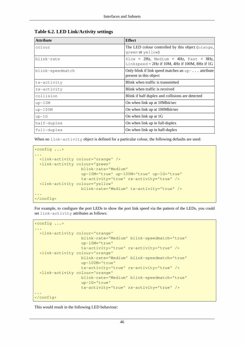
Interfaces and Subnets
46
Table 6.2. LED Link/Activity settings
Attribute Effect
colour The LED colour controlled by this object (orange,green or yellow)
blink-rate Slow = 2Hz, Medium = 4Hz, Fast = 8Hz,Linkspeed = 2Hz if 10M, 4Hz if 100M, 8Hz if 1G
blink-speedmatch Only blink if link speed matches an up-... attributepresent in this object
tx-activity Blink when traffic is transmitted
rx-activity Blink when traffic is received
collision Blink if half duplex and collisions are detected
up-10M On when link up at 10Mbit/sec
up-100M On when link up at 100Mbit/sec
up-1G On when link up at 1G
half-duplex On when link up in full-duplex
full-duplex On when link up in half-duplex
When no link-activity object is defined for a particular colour, the following defaults are used:
<config ...>... <link-activity colour="orange" /> <link-activity colour="green" blink-rate="Medium" up-10M="true" up-100M="true" up-1G="true" tx-activity="true" rx-activity="true" /> <link-activity colour="yellow" blink-rate="Medium" tx-activity="true" />...</config>
For example, to configure the port LEDs to show the port link speed via the pattern of the LEDs, you couldset link-activity attributes as follows:
<config ...>... <link-activity colour="orange" blink-rate="Medium" blink-speedmatch="true" up-10M="true" tx-activity="true" rx-activity="true" /> <link-activity colour="orange" blink-rate="Medium" blink-speedmatch="true" up-100M="true" tx-activity="true" rx-activity="true" /> <link-activity colour="orange" blink-rate="Medium" blink-speedmatch="true" up-1G="true" tx-activity="true" rx-activity="true" />...</config>
This would result in the following LED behaviour:

Interfaces and Subnets
47
Table 6.3. Example modified Port LED functions
Orange Green Yellow Indication
Off Off Off Link down
On/Blinking Off Off Link up at 10Mbit/s / Tx orRx Activity
Off On/Blinking Off Link up at 100Mbit/s / Txor Rx Activity
Off Off On/Blinking Link up at 1Gbit/s / Tx orRx Activity
48
Chapter 7. Session HandlingThis chapter describes sessions, session-tracking, and how the rules for session creation can be usedto implement Firewalling, subject specific traffic flows to traffic-shaping, and perform address mappingtechniques including conventional Network Address Translation (NAT).
Session-tracking is also involved in the route override functionality of the FB2900 - this is covered inSection 8.6.
7.1. Routing vs. FirewallingA network router is a device whose role is to forward packets entering the device out onto an appropriatephysical interface, based primarily, or solely, on the destination IP address of the packets. Typically the sourceaddress of each packet is not considered in the forwarding decision.
A firewall on the other hand is a device whose primary role is to filter traffic based on specified criteria. Sincemost network communication between two end-points is bi-directional, any such filtering must correctly handlethe packets flowing in both directions that constitute a specific end-to-end 'flow' (for connection-less protocols,such as UDP) or 'connection' (for connection-orientated protocols, such as TCP).
In practice, a firewall appliance will have to make routing decisions too.
7.2. Session TrackingEach flow or connection is identifiable by the set of parameters that makes it unique ; two of these parametersare the network addresses of the two end-points. For protocols that support multiplexing of multiple flows orconnections to/from a single network address - UDP and TCP both support this - the remaining parametersare the identifiers used to do the multiplexing. For both UDP and TCP, this identifier is a port-number, whosescope is local to the end-point, and is therefore usually different at each end-point for a given flow/connection.
Normally, only one of the two port-numbers involved will be known a priori - this will be the documentedport-number used for a specific service at the server end (for example, port 80 for an HTTP service) ; the otheris dynamically chosen from the available pool of unused port numbers at the client end.
Therefore, the filter criteria can only specify that known port-number ; the other port-number can only bedetermined by inspection of the IP packet payloads, discovering which protocol is being carried, and usingknowledge of the protocol to extract the port-number.
This information must then be stored, and held for a duration not less than the duration that communicationsoccur over the flow or connection. This information defines a session, and is stored in the session-table. Thekey point of the session table entry is that it will then cause return traffic to be allowed, and sent to the correctplace. Without the session table entry, the FB2900 would have no way of knowing that the return traffic is partof an allowed (by firewalling rules) session, and it would likely be dropped due to firewalling.
The overall process of analysing packet payloads and maintaining the session-table is referred to as session-tracking.
Session-tracking is necessary to be able to implement firewalling using the kind of rules you might expect tospecify - for example :
"allow TCP connection to port 80 on IP address 10.1.2.3, from any IP address" (note source port number notspecified)
Session-tracking will therefore be present in a firewall, but not required in a router.

Session Handling
49
The contents of the session-table can be viewed in the web user interface by clicking "Sessions" in the "Status"menu. You will normally see two entries per session, one with a green background and one with a yellowbackground. These two 'entries' are the forward and reverse details of the session.
7.2.1. Session termination
For connection-orientated protocols such as TCP, the session-tracking is able to detect connection closure anddelete the session from the session-table.
For protocols such as UDP, which will likely be carrying a higher-level protocol that may well itself implementsome form of connection-orientated data transfers, further inspection and analysis of communications is notdone by the FB2900. To do so would require support for a very wide range of protocols that are carried overUDP, and this is generally not practical.
Instead, all sessions (including TCP ones) have an associated time-out value - if no packets matching the sessionarrive for a period equal to the time-out value, the session is deleted automatically. This is adequate for mostcases, but may require selection of a suitable time-out value based on knowledge of how frequently the higher-level protocol sends packets. An unnecessarily high time-out may cause the session-table to become populatedwith a significant number of sessions that correspond to flows or connections that have actually ceased.
However, the FB2900 has highly efficient handling of session tracking, both in terms of memory usage andprocessor load, so in practice it can easily handle very large session tables (hundreds of thousands of entries).
Note that TCP sessions also have time-outs ; this is necessary since the connection may not be cleanly closed,for example one end may crash - if there were no time-out, the session-table would hold a stale entry until theFB2900 was rebooted.
7.3. Session Rules
7.3.1. Overview
As each packet arrives, the FB2900 determines whether the packet is part of an existing active session by doinga look-up in the session table. If a matching session is found, the session-table entry details determine howthe packet is handled. If no matching session is found, the list of session-rules is then analysed to determinewhether a new session should be established, or whether the traffic should be dropped or rejected.
Each session rule contains a list of criteria that traffic must match against, and contains an action specificationthat is used in the logic to decide whether the session will be allowed or not. The session rule can also :-
• make the session subject to traffic-shaping
• specify that Network Address Translation should occur
• specify that address and/or port mapping should occur
Session-rules are grouped into rule-sets, and together they are involved in a well-defined processing flowsequence - described in the next section - that determines the final outcome for a candidate session.
Tip
The FB2900 provides a method to illustrate how specific traffic will be processed according to theflow described. This can be used to 'debug' your rules and rule-sets, or simply to improve / verifyyour understanding of the processing flow used to determine whether sessions are established. Referto Section 15.1 for details.

Session Handling
50
7.3.2. Processing flowThe following processing flow applies to rules and rule-sets :-
• Rule-sets are processed sequentially.
• Each rule-set can optionally specify entry-criteria - if present, these criteria must be matched against for therules within the rule-set to be considered.
• If the rule-set's entry-criteria are not met, processing immediately procedes with the next rule-set, if any.
• If the rule-set's entry-criteria are met, or no entry-criteria were specified, processing of the rules within thatrule-set begins :-
• Rules are processed sequentially.
• Each session-rule specifies criteria, and an action to be taken when traffic meets that criteria ; the actionvalues are their meanings are shown in Table 7.1. Once a rule matches, no more rules in that rule set areconsidered.
• If all of the rules in a rule-set have been considered, and none of them matched against the traffic, thenthe action specified by the no-match-action attribute (of the rule-set) is taken. The available actionsare the same as for a session-rule.
Table 7.1. Action attribute values
"action" attribute Action taken
drop immediately cease rule processing, 'quietly' drop thepacket and create a short-lived session to drop furtherpackets matching the rule criteria
reject immediately cease rule processing, drop the packet,send rejection notification back to the traffic sourceand create a short-lived session to drop further packetsmatching the rule criteria
accept immediately cease rule processing, and establish anormal session
continue 'jump' out of the rule-set ; processing resumes with thenext rule-set, if any
ignore immediately cease rule processing, 'quietly' drop thepacket but do not create a short-lived session (incontrast to the drop action)
The short-lived session that is created when either drop and reject are actioned will appear in the sessiontable when it is viewed in the web user interface (or via the CLI) - see Figure 7.1 for an example of ICMPsessions resulting from some pings ; the session lifetime is around one second.
Figure 7.1. Example sessions created by drop and reject actions
Session Handling
51
Note that drop and reject both drop packets, with the difference only being whether notification of thisis sent back to the traffic source.
TipFor a short period after startup the actions of drop and reject are treated as ignore. This is sothat a reboot which would forget all sessions allows sessions that have outbound traffic which is notNAT stand a chance of re-establishing by use of outbound traffic. Without this delay, incoming trafficwould create a drop/reject short lived session and could send an icmp error closing the connection.This is configurable per rule-set.
Note
It is possible to mis-understand the function of the no-match-action attribute, given where it isspecified (i.e. an attribute of the rule-set object). This is particularly true when using XML. If you areunfamiliar with the FB2900's session rule specifications, you may interpret the no-match-actionas specifying what happens if the rule-set's entry-criteria are not met (i.e. at the beginning of processinga rule-set).
no-match-action specifies what happens after the entry-criteria were met, and all the rules wereconsidered, but none of them matched ("no-match") i.e. at the very end of processing a rule-set.
Caution
If all rule-sets have been considered, and no action has specified that the session should be droppedor rejected, it will be ALLOWED. The factory default rule-sets have a firewall rule with no-match-action set to drop to avoid this happening by mistake.
We recommend you use the firewall diagnostic tests to verify that you have constructed rule-setsand rules that provide the firewalling you intended. We also highly recommend external intrusiontesting to verify behaviour. We also recommend that firewalling is done using the method describedin Section 7.3.3.1.
This processing flow is illustrated as a flow-chart in Figure 7.2 :-

Session Handling
52
Figure 7.2. Processing flow chart for rule-sets and session-rules
Packet arrives, no m atching session exists
Examine nextrule-set object
All rule-setsprocessed?
No
Yes
No Entry-criteriamet?
Yes
All rules inthe rule-setprocessed?
Examine nextrule object
"no-match-action" is
'continue'?
Yes
SessionAllowed
Yes"no-match-action" is'accept'?
No
No("no-match-action" is 'drop' / 'reject')
/ 'ignore'
No
"action" is'continue'?
Yes"action" is'drop' / 'reject'
/ 'ignore' ?
No
No ("action" is 'continue' or 'accept')
Rulecriteriamet?
Yes
SessionAllowed
Sess ionAllowed
PacketDropped (*)
No
Yes
Yes
Rule Process ing
Process ing continueswith next rule-set
Rule-Set Process ing
Start process ing ruleswithin the rule-set
No rules within therule-set matched
Apply any changesspecified in the rule
(*) for "drop" and "reject", a short-lived 'drop' sess ion is created
PacketDropped (*)

Session Handling
53
It is helpful to understand that a session rule contributes to the final set of information recorded in the session-table entry - a rule does not necessarily completely define what the session-table will contain, unless it is theonly rule that matches the traffic under consideration. It is for this reason, that the rules contain attributes withnames such as 'set-nat' - the 'set' refers to the action of setting a flag or a parameter in the session-table entrythat is being 'constructed'.
It is possible, and quite common, for more than one rule (in different rule-sets) to match given traffic. In suchcases, the rules generally serve different purposes - earlier ones might be for firewalling, whilst later ones mightbe used to subsequently assign some of the allowed-traffic to traffic-shaping. In such cases, an earlier rule willuse the continue action to jump out of the earlier rule-set.
7.3.3. Defining Rule-Sets and RulesA rule-set is defined by a rule-set top-level object. To create or edit rule-sets in the web user interface,select the "Firewall" category icon - here you will see the list of existing rule-set objects (if any), and a"Add" link next to each.
To create a new rule-set, click on an "Add" link to insert a new rule-set before the one associated with the link.This will take you to a new rule-set defintion. Editing an existing rule-set works similarly - click the "Edit"link next to the rule-set you want to modify.
As described in Section 7.3.2, a rule-set can optionally specify entry-criteria - in the web user interface, thesecome under the heading "Matching criteria for whole set", when editing a rule-set definition. The entry-criteriaare detemined by the following attributes, all of which are optional, but if they are specified, then the criteriamust be met for processing of the rules within the rule-set to occur. These are also critera than can be specifiedon individual rules within a rule-set :-
• criteria regarding where the session is originating from :-
• source-interface : one or more interfaces
• source-ip : source IP address, or address range(s)
• source-port : source protocol port number, for protocols that use the port number concept e.g. TCP andUDP
• source-mac : (on individual rules) Only matches where from an Ethernet interface. Allows the sourceMAC if the initial packet to be checked for the initial bytes.
• criteria regarding where the target of the session is :-
• target-interface : one or more interfaces
• target-ip : target IP address, or address range(s)
• target-port : target protocol port number, for protocols that use the port number concept e.g. TCP and UDP
• general criteria :-
• protocol : the IP protocol number
There are also checks for just ip being either source or target IP, interface being either source or targetinterface.
Note
There is a special case for RFC5735 handling of source-ip and target-ip when they arespecified as IPv4 and within 0.0.0.0/8-31. In this case the check is made for same network, so if you

Session Handling
54
checked for target IP of, say, 0.0.0.0/24, that would pass if the target IP is within the same /24 as thesource IP. This only works on IPv4, and only on subnets, not ranges, and only on source-ip andtarget-ip checks. Although not in RFC5735, the same logic is applied to IPv6 for ::/32-127.
A rule-set can also be named by setting the name attribute value, and enabled/disabled under control of aprofile. The comment attribute is a general purpose comment field that you can use to briefly describe thepurpose of the rule-set.
Under the heading "Individual rules, first match applies", you will see the list of session-rules within the rule-set. A session-rule is defined by a rule object, which is a child object of a rule-set object.
Below the list of session-rules, you will see the no-match-action attribute, which is mandatory and hasone of the values shown in Table 7.1. Recall that this attribute specifies the action to take if all of the rules ina rule-set have been considered, and none of them matched against the traffic.
7.3.3.1. Recommended method of implementing firewalling
Although there are likely numerous ways in which you can construct workable rule-sets that implementfirewalling in addition to any traffic-shaping or NAT etc., we recommend that you implement firewalling asfollows :-
• create one or more rule-sets that are specifically for firewalling
• use one rule set per interface, with the interface specified as the target-interface in the entry criteria, suchthat the rule-set relates to sessions "to" that interface
• implement a 'default drop' policy on each firewalling rule-set, such that you have to list exceptions tothis policy to allow sessions to the specified target interface - to implement this policy, you set the no-match-action attribute to either drop or reject
• ensure these firewalling rule-sets appear before any other (non-firewalling) rule-sets
• create subsequent rule-sets if necessary to perform any modifications to the session, such as NAT'ing, or tosubject sessions to traffic shaping
Caution
If you have a large number of interfaces (for example, more than just WAN and LAN), you must takecare that you have covered all the interfaces that need to be firewalled
Alternatively, you could have a single firewalling rule-set without any entry-criteria and with no-match-action attribute set to either drop or reject - that way, all traffic, regardless of its origin, or itscharacteristics, will be subject to the 'default drop' policy. A disadvantage of this approach is that you willneed to specify target interfaces in every rule in order to replicate the functionality of the method describedpreviously.
In any case, you can verify that your rule-sets function the way you intended using the diagnostic facilitydescribed in Section 15.1.
The XML fragment below shows a small firewalling rule-set for an interface, with a 'default drop' policy :-
<rule-set name="firewall_to_LAN" target-interface="LAN" no-match-action="drop"> <rule name="web"

Session Handling
55
target-port="80" protocol="6" comment="WAN access to company web server"/> </rule-set>
Rule-set is named "firewall_to_LAN". The rule-set only applies to sessions targetting the "LAN"interface, from any other interface. The action to perform when no rule within the rule-set applies, is to"drop".Rule is named "web", the criteria for matching the rule only specifies that the traffic must be targettingTCP (protocol 6) port 80. The action attribute is not present, so the action defaults to "continue" -processing continues with next rule-set. Unless any subsequent rule (in a later rule-set) drops the session,the session will therefore be allowed.If no rule matched the traffic, then the "no-match-action" of the rule-set is applied here - in this case thesession is dropped, thus enforcing a 'default drop' policy
Note
The FB2900 itself does not generally need firewalling rules to protect against unwanted or maliciousaccess, as the access controls on services can provide this protection directly - see Chapter 14 fordiscussion of access controls.
.
You may want to perform some outbound traffic filtering as well. This would normally want to work theother way around to inbound filtering. With inbound you want block all but those listed hence using a no-match-action of drop. However, for outbound you will typically want a allow all but those listed. To thisend, you could create a rule-set for traffic from inside interfaces, such as LAN and a no-match-action ofcontinue. Then include specific rules for those things you wish to block with an action of reject.
7.3.3.2. Changes to session traffic
Normally, a session table entry holds enough information to allow return traffic to reach its destination, withoutpotentially being firewalled.
However, a session-rule can specify certain changes to be made to the outbound traffic in a session, and thesession-table entry will hold additional information that allows the FB2900 to account for these changes whenprocessing the return traffic.
For example, a session-rule can specify that the source IP address of the outbound packets be changed, suchthat they appear to be coming from a different address, typically one owned by the FB2900 itself. Return trafficwill then be sent back to this modified address - assuming that the intention is that this traffic reach the originalsource IP address, the FB2900 will change the destination IP address in return traffic to be the original sourceIP address. It can do this because it has stored the original source IP address in the session table entry.
The set-source-ip, set-source-port, set-target-ip and set-target-port attributesrequest this kind of change to be made.
NoteThe set-source-ip and set-target-ip value is normally a single IP address. However arange or prefix can be specified instead. If this is used then the IP that is set will be in the range/prefixbut offset from the base depending on the offset withing the matching rule that matched the IP. Thismeans matching in the rule and not the rule-set so may mean duplicating the matching source/target ip setting. E.g. if you match a /64 prefix, and then set a new IP with a /64 prefix, it will mapto the same last 64 bits. This allows general prefix mapping, and allows things like NAT64 mappinga /96 of IPv6 space to all of IPv4 space, for example. If the set ip is an IPv4 range not a power of 2prefix then the last 32 bits of the offset from the matching range is used, modulo the target range size.

Session Handling
56
Note
Any rule that changes part of the "session" will affect the matching criteria in subsequent rule-sets andrules - i.e. they test the changed version of the session.
Quite separately to firewalling and session tracking, the FB2900 has to route traffic, and this is done usingnormal routing logic (see Chapter 8). The routing is done based on the destination IP address, as normal.However, it can be useful for session tracking rules to override the normal routing. The set-gateway allowsa different IP address to be used for the routing decision, instead of the actual destination IP in the packets.Setting this causes all subsequent packets matching the session to use that gateway IP for routing decisions.
7.3.3.3. Graphing and traffic shaping
The set-graph and set-reverse-graph attributes cause the session traffic to be graphed, and thereforepossibly be subject to traffic shaping ; they perform the same function as the graph attribute that can bespecified on many different objects, as described in Chapter 10.
Each direction of the final established session can have a graph set. The normal set-graph attribute setsthe forward direction graph, and set-reverse-graph sets the reverse session graph (remember, sessionshave two sides). Because of this, with set-graph, the graph "Tx" direction will be the direction in whichthe session was established, and the "Rx" direction is therefore the opposite direction. With set-reverse-graph, the "Tx"/"Rx" directions are swapped compared to using set-graph.
There is also an option for set-graph-source-mac which causes the session to set a (forward) graph thatis based on the MAC address of the source packet, if from an Ethernet interface. The graph is created if it doesnot exist. If set-graph is also defined then each new session created also causes the speed settings and longterm shaper parameters to be copied from the named graph (in set-graph) to the MAC named graph beingused. This is aimed at management of open WiFi and the like allowing a named shaper to be defined and acopy of its settings created for each client based on MAC address.
7.3.3.4. Configuring session time-outs
As discussed in Section 7.2.1, each session-table entry has a timer associated with it - this ensures that inactivesessions are removed from the session-table. Two time-out values are configurable :-
• Initial time-out : this time-out period begins when the first reply packet of the session arrives at the FB2900 ;it is specified by the set-ongoing-timeout attribute.
• Ongoing time-out : this time-out period begins when each subsequent packet of the session arrives at theFB2900 ; it is specified by the set-initial-timeout attribute.
NoteThe actual timeout used is taken from a list of timeouts, and set to the next highest available value. Thestatus/sessions list shows the timeout in force as well as useful flags for session started, and closed,and so on.
• The session timeout is actually maintained separately for each direction, and only when the timeout happensin both directions does the session get dropped. This allows one-sided keep-alive packets as often used byprotocols such as VoIP.
• The ongoing-timeout is set for both directions at once, only when both directions are considered to havestarted. The initial forward packet does not count as starting, but a further packet does. An ICMP errorpacket does not count to start a session either, and neither does a TCP packet that does not carry the ACKbit. These subtlties are designed to better handle unresponsive TCP endpoints and spoofed TCP packets evenif allowed through the firewall.
• There are default timeouts for UDP, TCP, ICMP, and other protocols. For UDP the timeout also depends onthe target port with ports 1024 and higher getting a longer timeout as per RFC recommendations.

Session Handling
57
7.3.3.5. Load balancing
Session tracking rules can include an additional set of share records which define a choice of possible changesto make when setting up the session. This choice is normally random and based on a weighting for each choice.
This allows various forms of load balancing to be applied. E.g. you could port map to one of a set of webservers or mail servers.
Each share can also have a profile which can be used to exclude the option from the selection - this is typicallytied to a ping or some other test to confirm the choice makes sense. In the example of web services being loadbalanced, a ping based profile could confirm each web server is actually up.
Normally the choice is random, but there is an option (hash) which can be set to make the choice determinedbased on a has of the source and target IP address. This allows consistent mapping of sessions to the sameserver. As the choice depends on the set of servers which have an active profile, if the profiles change, sessionswill get a new consistent mapping based on IP addresses.
7.3.3.6. NAT-PMP / PCP (Port Control Protocol)
The FireBrick supports protocols that allow devices on your LAN to request port mapping and firewall holesusing RFC6886 (NAT-PMP) and RFC6887 (PCP). These are newer protcols than uPnP (univeral plug andplay) and used by many devices and applications. PCP is the later protocol and allows handling of IPv6 andalso allows finer control such as opening a firewall hole for a specific block of external IPs only.
It is importamt to understand that there are two stages to the use of these protocols. Firstly a device on the localnetwork will send a message to the FireBrick as the gateway device requesting a mapping or firewall hole.Secondly, a session may be created that matches that mapping or firewall hole, and needs to be allowed or notaccoridng to normal firewall rules.
The first stage is controlled by a setting on the subnet. By default, any subnet marked as nat="true" haspcp true as well, as does any subnet created using IPv6 Prefix Delegation. Settings on the interface and subnetcan override these defaults. Only if a subnet has pcp set will a NAT-PMP or PCP packet be accepted andprocessed to create mappings.
Once created, the mappings can be viewed on the status page for sessions. When a new session starts it ischecked against these mappings. The mappings may relate to incoming traffic or outgoing traffic. The mappingis applied to the new session, so, for example, incoming traffic to a specific mapped external port may bemapped to an internal device IP and port. This mapped traffic is then processed via the firewall rules as normal,but as it is already mapped it allows the firewall rules to consider the target (typically a private) IP address andport. This allows much finer control than would be possible otherwise, and one can, for example, easily allowall mapped traffic to specific internal devices such as gaming consoles.
In order to make the firewall rules easier to manage, any mapped traffic using a NAT-PMP/PCP rule will beflagged as pcp and so you can make rules relating specifically to these mapped sessions. As such a rule toallow all incoming mapped sessions is simple to create.
It is important to note that by default, on factory reset, the firewall rules block all incoming sessions to theLAN, and this will mean that even mapped sessions set up using NAT-PMP or PCP will also be blocked. Anadditional rule is necessary to allow such sessions. This rule can test for destination IPs even where these areprivate IP addresses on the LAN as the mappings are already applied before checking firewall rules. This meansthe FireBrick can be set to allow NAT-PMP and PCP sessions only for specific devices, ports and protocolsby using firewall rules.
TipThe factory default config has a rule that is set to disabled profile. Simply changing this to not havea profile will allow all mapped traffic in to your LAN.

Session Handling
58
NoteNAT-PMP and PCP have no authentication. Any device on your LAN can send a message to createmappings. Whilst the FireBrick does not allow the PCP third party option, it is possible for packets tohave spoofed IP and even MAC addresses to open ports to other devices. As such a blanket acceptanceof all mappings is a security risk, and ideally you should consider which mappings you wish to apply.
NoteNAT-PMP and PCP can set up outgoing connections as well as incoming. These would typically beallowed through a firewall, but this allows long timeouts, so for example a long timeout outgoingUDP session could be created that then allows traffic back the other way for way longer than mightotherwise have been expected. Obviously firewall rules can be used to check outgoing NAT-PMP/PCP sessions and these can even override the timeouts requested by NAT-PMP/PCP.
TipWith pcp allowed on a subnet you can see what mappings are created, and then carefully decide whichmappings you wish to allow in firewall rules.
7.4. Network Address TranslationNetwork Address Translation (NAT) is the general term used for sharing one IP address between multipledevices. It is typically a feature of broadband routers that are designed to operate with one external IP addressand private (RFC1918) addresses on the inside (such as 192.168.x.x).
In additional to NAT, there are several ways in which one can do various types of port mapping and IP mappingwhich are described in the general session tracking and firewalling rules above. However, NAT is, itself, acomplex issue and this section describes some of the issues and recommendations for how best to use NATon a FireBrick.
7.4.1. When to use NATNAT breaks the way Internet Protocol was designed as it stops end to end addressing and routing of packets.This causes problems with all sorts of protocols that sensibly expect IP to work as designed, and even some thatassume NAT is in use. NAT is not itself a consistent and predictable process, and so it makes it very difficultfor protocol designed.
Because of the many issues with NAT it is strongly recommended that NAT is only ever used where it isunavoidable. This is specifically where the availability of public IP addresses is limited.
Unfortunately with legacy IP version 4 addresses the supply of address space is now limited and most ISPs areonly providing a single IPv4 address with an Internet Connection (or charging where more are provided). Thismeans that it is common to require NAT for IPv4 on a typical Internet connection.
TipIt is strongly recommended that you make use of PPPoE to connect to such an Internet connection,thereby affording the FireBrick itself with the single public IPv4 address assigned to the connection.This allows a number of features to work without use of NAT, including DNS relay, VoIP, and otherinternal operations of the FireBrick (e.g. clock setting, s/w updates, etc).
NoteThere is never any excuse to use NAT with IPv6. There is a virtually unlimited supply of IPv6address space and you should have no problem obtaining necessary IPv6 address space from your ISP(assuming they do the current Internet Protocol, which is version 6). Remember, NAT is not a meansof protection - the FireBrick has a firewall for that, NAT is a workaround for IP address sharing,something that is simply not necessary with IPv6 and should not be encouraged.

Session Handling
59
7.4.2. NAT ALGsBecause of the many problems with NAT and the ways in which many protocols are broken by its use, manyNAT devices (such as broadband routers) will provide an Application Layer Gateway (ALG) as part of theNAT implementation. This provides special case handling for each higher level protocol or system making useof NAT that the device knows of, and provides work-arounds for the issues caused by NAT. In some cases thismay simply be customised session timeout, but in some cases the support can be extensive and make majorchanges to the payload of packets passed through the device.
ALGs have a number of problems. Obviously they only work at all where the device knows of the protocol inquestion, and this is a major draw back for new protocol development. However, they are often imperfect in theway they work. It is not uncommon for ALGs designed to support VoIP using SIP to be significantly flawedsuch that you are better off turning off the ALG and leaving end devices to work around the NAT themselves.
The real solution to all of the issues with NAT is not ALGs, as they are simply not a scalable work-around forproblems. The solution is the use of IPv6, the current Internet Protocol version. The FireBrick is designed fromthe ground up to support IPv6 and we recommend the use of IPv6 wherever possible.
NoteThe FireBrick provides no ALGs whatsoever for any form of NAT or IP/port mapping. This is adeliberate policy decision. However, there are a number features in the FireBrick that allow the correctoperation of many protoicols. These include the FireBrick SIP VoIP PABX server which allows itto act as a proper SIP gateway between locally connected (e.g. on RFC1918 addresses) and externalSIP devices using the external IPv4 on PPPoE. The FireBrick also uses RFC recommended sessiontimeouts for UDP when NAT is applied to allow many protocols to continue to work with minimalkeep-alive packets. The use of customised session timeouts and port and IP mapping in the firewallingrules also allow for special cases to be accomodated where necessary. In addition, support for NAT-PMP and PCP allow port mapping and firewall holes to be created by devices on your network toallow NAT traversal for devices that use these protocols (sucessors to uPnP).
7.4.3. Setting NAT in rulesThe rules for firewalling allow a set-nat setting to be set true or false. Rules in later rule-sets can override thissetting just like any other setting in the firewall rules.
NoteThe setting of the NAT flag causes NAT to be applied, and this will change the source IP and portused for the session. However, unlike the explicit setting of a source IP or port in a rule, which causesthe next rule-set to see the new changed setting, the NAT setting does not actually make these changesuntil the end of the processing of the rule-sets. i.e. a subsequent rule-set or rule cannot test the newsource-ip or source-port that NAT will apply.
7.4.4. What NAT doesWhat the NAT setting does is cause the FireBrick to change the source IP and port used for the session. It picksan IP based on the interface to which the traffic will finally be sent, and uses the most appropriate IP addressthat it can to try and ensure correct return traffic to that IP address.
The port that is chosen is picked from a pool of available source port addresses that are not currently in use.This ensures that the reply traffic can be correctly matched with the specific session even if multiple sessionsare using the same original ports.
NoteIt is possible to set the NAT attibute but also to explicitely set the source IP to be used. This will stillallocate an available port, but will use the chosen source IP address. Care must be taken to ensure

Session Handling
60
that the IP chosen is one that will allow the return traffic to be routed via the FireBrick to allow theNAT to be reversed.
7.4.5. NAT with PPPoEWhen using a PPPoE connection you may have a single IPv4 address assigned to the connection and so willneed to NAT traffic sent down that connection to the Internet. To accommodate this there is a nat setting whichcan be enabled on the PPPoE configuration.
If this NAT setting is enabled then the default for all IPv4 traffic directed to the PPPoE session is for NAT tobe used. This default applies if the firewalling rules have not otherwise explicitely set the NAT setting for thetraffic in question. i.e. this can be overridden by specific firewalling rules.
NoteThe NAT setting on PPPoE will not cause NAT to be set for IPv6 traffic.
TipIt is possible, of course, to use rule-sets and rules to control exactly when NAT applies rather thanusing the NAT setting on the PPPoE config. However, if the PPPoE connection only has one IPv4address assigned, as is often the case, then setting NAT on the PPPoE config is usually the simplestway to achieve the configuration.
7.4.6. NAT with DonglesJust as with PPPoE, there is a NAT setting which will cause traffic sent via the dondle to have NAT set bydefault, unless overridden by firewall rules. However, in the case of a dongle it is so rare to have a block ofIPv4 addresses the NAT setting is enabled by default in the dongle configuration.
NoteThe NAT setting on a dongle will not cause NAT to be set for IPv6 traffic.
TipIt is possible, of course, to use rule-sets and rules to control exactly when NAT applies rather thanusing the NAT setting on the dongle config. However, if the dongle connection only has one IPv4address assigned, as is usually the case, then setting NAT on the dongle config is usually the simplestway to achieve the configuration.
7.4.7. NAT with other types of external routingWhere NAT is needed for other types of external routing, you can set NAT using explict rule-sets and rules.A simple rule-set at the end of all rule-sets can easily be set up to identify traffic being sent to a specific targetinterface and set the NAT setting.
TipIt is recommended that you use PPPoE where possible rather than an external router which mayadditionally perform an additional layer of NAT.
7.4.8. Mixing NAT and non NATIn some cases you may have a combination of real routed IPv4 addresses and some RFC1918 private addresses.These could be on different interfaces and subnets.
Typically in such cases you want to use NAT for external communications only when using the privateaddresses, but non-NAT when using the public addresses. The logic can be complicated where there may be

Session Handling
61
fallback arrangements, such as a dongle, which may have to use NAT for all traffic even the normally publicrouted addresses if the dongle does not have routing for these addresses.
The recommended way to handle this is a rule-set at the end of rule-sets for handling NAT, in which a specificrule is created to match traffic being sent to the external interface (e.g. PPPoE) which is from an RFC1918address and setting NAT mode in such cases. Using this arrangement ensures that traffic internally betweenRFC1918 and public IP addresses can continue without using NAT internally.
TipFor fallback arrangements such as a dongle where all traffic needs to use NAT, simply set the NATmode on the dongle configuration. This saves having more complex rule-sets to handle the fallbackcase.
7.4.9. Carrier grade NATCarrier grade NAT (CGN) is where an ISP provides end users with a private address and provides a furtherlevel of NAT in the network (within the carrier).
Ideally you should try and make use Internet connections without CGN, but if you have to then you are likely toencounter additional issues with NAT. CGNs do often include some ALGs, but they bring all of the issues withNAT to a new level. As ever we recommend using PPPoE to avoid an extra layer of NAT in a broadband router.
In some cases the FireBrick may be expected to provide a carrier level of NAT in terms of number of sessionshandled. Whilst the FireBrick does not have any ALGs, it can be very effective, and it supports overloadingof ports. This means that the allocation of ports for NAT allows multiple sessions that are to different targetIP addresses and ports to come from the same port on the FireBrick, allowing use of the same port multipletimes. This allows a lot more sessions that would otherwise be expected based on number of TCP and UDPports available. This overloading of ports is automatic and part of the way the FireBrick handles NAT.
7.4.10. Using NAT setting on subnetsFor backwards compatibility with older FireBricks there is a NAT setting on the subnet config. The idea is thata subnet defined as an RFC1918 private block can simply be tagged as NAT. The effect is that any traffic fromthat subnet has NAT set by default. Again, this can be overridden by firewall rules.
TipThe problem with this method is that all traffic from the subnet is NAT, even if to another subnet onthe same FireBrick, and this is often not the case. This can be useful in very simple configurationswhere the FireBrick only has the one private subnet, but in most cases it is better to set NAT on aPPPoE or dongle interface and not use the NAT setting on the subnet configuration.

62
Chapter 8. Routing
8.1. Routing logicThe routing logic in the FB2900 operates primarily using a conventional routing system of most specific prefix,which is commonly found in many IP stacks in general purpose computers and routers.
Conventional routing determines where to send a packet based only on the packet's destination IP address, andis applied on a 'per packet' basis - i.e. each packet that arrives is processed independently from previous packets.
Note that with this routing system, it does not matter where the packet came from, either in terms of source IPaddress or which interface/tunnel etc. the packet arrived on.
The FB2900 also implements more specialised routing logic that can route traffic based on other characteristics,such as source address, that can be used when routing based on destination IP address alone is insufficient. Thisis linked in to the session tracking logic (see Chapter 7).
A route consists of :-
• a 'target' specifying where to send the packet to - this may be a specialised action, such as silently droppingthe packet (a 'black-hole')
• an IP address range that this routing information applies to - the routing destination
A routing table consists of one or more routes. Unlike typical IP stacks, the FB2900 supports multipleindependent routing tables.
Routing destinations are expressed using CIDR notation - if you are not familiar with this notation, please referto Appendix B for an overview. Note that ip-groups cannot be used when defining subnets or routes. IP-groupsallow arbitrary ranges and not just prefixes, but routes can only use prefixes.
There are two cases that deserve special attention :-
• A routing destination may be a single IP address, in which case it is a "/32" in CIDR notation (for IPv4).The /32 part (for IPv4) or /128 (for IPv6) is not shown when displaying such prefixes.
• A routing destination may encompass the entire IPv4 (or IPv6) address space, written as 0.0.0.0/0 (forIPv4) or ::/0 (for IPv6) in CIDR notation. Since the prefix is zero-length, all destination IP addresses willmatch this route - however, it is always the shortest-prefix route present, and so will only match if there areno more specific routes. Such routes therefore acts as a default route.
The decision of where to send the packet is based on matching the packet's destination IP address to one ormore routing table entries. If more than one entry matches, then the longest (most specific) prefix entry is used.The longest prefix is assumed to be associated with the optimal route to the destination IP address, since it isthe 'most specific', i.e. it covers a smaller IP address range than any shorter matching prefix.
For example, if you have two routes, one for 10.0.1.32/27 , and another for 10.0.0.0/8 (which encompasses10.0.1.32/27), then a destination IP address of 10.0.1.35 will match the longest-prefix (smallest address range)"/27" route.
The order in which routes are created does not normally matter as you do not usually have two routes that havethe same prefix. However, there is an attribute of every route called the localpref which decides betweenidentical routes - the higher localpref being the one which applies. If you have identical routes with thesame localpref then one will apply (you cannot rely on which one) but it can, in some cases, mean youare bonding multiple links.

Routing
63
Tip
You can show the route(s) that apply for a specific destination IP address or address range using theCLI command show route. You can also see a list of all routes in a routing table using the CLIcommand show routes. There is also a routing display on the Diagnostics control web pages.
8.2. Routing targetsA route can specify various targets for the packet :-
Table 8.1. Example route targets
Target Notes
an Ethernet interface (locally-atached subnet) requires ARP or ND to find the device on the LAN towhich the traffic is to be sent.
a specific IP address (a "gateway") the packet is forwarded to another router (gateway) ;routing is then determined based on the gateway's IPaddress instead
tunnel interface such as L2TP, PPPoE or FB105tunnels.
such routes are created as part of the config for theinterface and relate to the specific tunnel.
special targets e.g. the FB2900 itself, or to a black hole (causes alltraffic to be dropped)
These are covered in more detail in the following sections.
8.2.1. Subnet routesWhenever you define a subnet or one is created dynamically (e.g. by DHCP), an associated route isautomatically created for the associated prefix. Packets being routed to a subnet are sent to the Ethernetinterface that the subnet is associated with. Traffic routed to the subnet will use ARP or ND to find thefinal MAC address to send the packet to.
In addition, a subnet definition creates a very specific single IP (a "/32" for IPv4, or a "/128" for IPv6) routefor the IP address of the FB2900 itself on that subnet. This is a separate loop-back route which effectivelyinternally routes traffic back into the FB2900 itself - i.e. it never appears externally.
A subnet can also have a gateway specified, either in the config or by DHCP or RA. This gateway is just likecreating a route to 0.0.0.0/0 or ::/0 as a specific route configuration. It is mainly associated with the subnet forconvenience. If defined by DHCP or RA then, like the rest of the routes created by DHCP or RA, it is removedwhen the DHCP or RA times out.
Example: <subnet ip="192.168.0.1/24"/> creates a route for destination 192.168.0.0/24 tothe interface associated with that subnet. A loop-back route to 192.168.0.1 (the FB2900's own IPaddress on that subnet) is also created.
8.2.2. Routing to an IP address (gateway route)Routes can be defined to forward traffic to another IP address, which will typically be another router (oftenalso called a gateway) For such a routing target, the gateway's IP address is then used to determine how toroute the traffic, and another routing decision is made. This subsequent routing decision usually identifies aninterface or other data link to send the packet via - in more unusual cases, the subsequent routing decisionidentifies another gateway, so it is possible for the process to be 'recursive' until a 'real' destination is found.
Example: <route ip="0.0.0.0/0" gateway="192.168.0.100"/> creates a default IPv4 routethat forwards traffic to 192.168.0.100. The routing for 192.168.0.100 then has to be looked up to find

Routing
64
the final target, e.g. it may be to an Ethernet interface, in which case an ARP is done for 192.168.0.100to find the MAC to send the traffic.
There is logic to ensure that the next-hop is valid - the gateway specified must be routable somewhere and ifthat is via an Ethernet interface then the endpoint must be answering ARP or ND packets. If not, then the routeusing the gateway is supressed and other less specific routes may apply.
8.2.3. Special targetsIt is possible to define two special targets :-
• 'black-hole' : packets routed to a black-hole are silently dropped. 'Silent' refers to the lack of any ICMPresponse back to the sender.
• 'nowhere' (also called Dead End) : packets routed to 'nowhere' are also dropped but the FB2900 generatesICMP error responses back to the sender.
The blackhole and nowhere top-level objects are used to specify prefixes which are routed to these specialtargets. In the User Interface, these objects can be found under the Routes category icon.
When using BGP you can also define a network which is announced by default, along with any dead-end-community, and treated otherwise the same as nowhere.
8.3. Dynamic route creation / deletionFor data links that have an Up/Down state, such as L2TP or FB105 tunnels, or PPP links, the ability to actuallysend traffic to the route target will depend on the state of the link. For such links, you can specify route(s)to automatically create each time the link comes up - when the link goes down these routes are removedautomatically. Refer to Chapter 12 for details on how to achieve this via the routes attribute on the tunneldefinition objects.
This can be useful where a link such as PPPoE is defined with a given localpref value, and a separateroute is defined with a lower localpref value (i.e. less preferred), and therefore acts as a fallback route ifthe PPPoE link drops.
8.4. Routing tablesThe conventional routing logic described above operates using one of possibly many routing tables that theFB2900 can support simultaneously. Routing tables are numbered, with the default being routing table 0 (zero).
The various ways to add routes allow the routing table to be specified, and so allow completely independentrouting for different routing tables. The default table (table zero) is used when optional routing-tablespecification attributes or CLI command parameters are omitted.
Each interface is logically in a routing table and traffic arriving on it is processed based on the routes inthat routing table. Tunnels like FB105 and L2TP allow the wrapped tunnel packets to work on one routingtable and the tunnel payload packets to be on another. It is possible to jump between routing tables using arule in a rule-set.
Routing tables can be very useful when working with tunnels of any sort - placing the wrappers in one routingtable, allowing DHCP clients and so on, without taking over the default route for all traffic. The payload canthen be in the normal routing table 0.
8.5. BondingA key feature of the FB2900 is the ability to bond multiple links at a per packet level. This feature is onlyenabled on a fully loaded model of your FB2900.

Routing
65
Bonding works with routing and shapers together. (See Chapter 10 for details of shapers.)
The basic principle is that you have two or more routes that are identical (same target IP prefix) and have thesame localpref, so that there is nothing to decide between them. As described above this normally means oneof the routes is picked.
However, where the two (or more) routes are the same type of interface, and there are shapers applied to thoseroutes, then a decisions is made on a per packet basis as to which interface to used. The shapers are used todecide which link is least far ahead. This means that traffic is sent down each link at the speed of that link.
To make this work to the best effect, set the tx speed of the shapers on the links to match the actual link speed.E.g. for broadband lines, set the speed to match the uplink from the FB2900.
For L2TP use as an LNS, the graph created for each L2TP session has an agress speed automatically set basedon the speed details sent on the L2TP connection. These can also be overridden by a RADIUS response. Theeffect of this is that multiple lines that are connected to the same LNS and have the same IPs routed to the lineswill automatically per packet bond traffic down those lines.
8.6. Route overridesThe conventional routing logic described so far operates very much like any conventional router, with theaddition of some handling for bonding and duplicate subnets.
However the FB2900 also allows the possibility of route overrides which control routing in more more detail.This feature is part of session tracking functionality, and so applies on a per-session basis (contrasting with theper-packet basis for the conventional routing). For details on sessions, and session-tracking, refer to Chapter 7.
When establishing a session it is possible to scan an ordered list of rules which can consider not only the targetIP but also source IP, protocol, ports, and interfaces being used. The result is (typically) to set a routing targetIP for the session (and possibly a routing table to jump between tables).
Note
The destination IP in the packet header is not modified - rather, an 'overriding' routing target IP addressis stored in the session-table entry.
This is done for each direction on the session and remembered. This new target IP is then used on a per packetbasis in the same way as above instead of the destination IP address of the packet. This is the same as set-gateway in the normal session tracking logic. However, routing overrides are applied at the end of checkingrule-sets and applied both ways, allowing, in effect, a set-reverse-gateway.
Tip
Because the route-override just sets a new target routing IP and does not allow you to set a specifictunnel or such, you may want to have a dummy single IP address routed down a tunnel, and then useroute-override rules to tell specific sessions to use that IP as the gateway. Future software releasesmay provide a means to specify a tunnel as a routing gateway more directly.
NoteRoute override logic was originally devised to allow routing for use with tunneling protocols, but theyare usually better handled with much less configuration using routing tables. As such this feature israrely useful, and probably not the configuration setting you are looking for (waves hand in front ofyour face).

66
Chapter 9. ProfilesProfiles allow you to enable/disable various aspects of the FB2900's configuration (and thus functionality)based on things such as time-of-day or presence/absence of Ping responses from a specified device.
9.1. OverviewA profile is a two-state control entity - it is either Active or Inactive ("On" or "Off", like a switch). Once aprofile is defined, it can be referenced in various configuration objects where the profile state will control thebehaviour of that object.
A profile's state is determined by one or more defined tests, which are performed periodically. If multiple testsare specified, then the overall test result will be pass only if all the individual test results are pass. Assumingthe profile's state is Active, then when the overall test result has been 'fail' for a specified duration, the profiletransitions to Inactive. Similary, once the overall test result has been 'pass' for a specified duration, the profiletransitions to Active. These two durations are controlled by attributes and provide a means to 'filter' out shortduration 'blips' that are of little interest.
An example of a test that can be performed is a Ping test - ICMP echo request packets are sent, and replies areexpected. If replies are not being received, the test fails.
Profiles can be logically combined using familiar boolean terminology i.e. AND, OR and NOT, allowing forsome complex profile logic to be defined that determines a final profile state from several conditions. Whenconsidering the state of another profile, it is the previous second's state that is considered - i.e. profile statesare all updated in one go after considering all profiles.
By combining profiles with the FB2900's event logging facilities, they can also be used for automatedmonitoring and reporting purposes, where profile state changes can be e-mailed direct from the FB2900. Forexample, a profile using a Ping test can be used to alert you via e-mail when a destination is unreachable. Theprofile logic tests are also done based on the defined interval.
The current state of all the profiles configured on your FB2900 can be seen by choosing the "Profiles" itemin the "Status" menu.
Tip
You can also define dummy profiles that are permanantly Active or Inactive, which can be usefulif you wish to temporarily disable some functionality without deleting configuration object(s). Forexample, you can force an FB105 tunnel to be Down, preventing traffic from being routed throughit. Refer to Section 9.2.4 for details.
9.2. Creating/editing profilesIn the web user interface, profiles are created and edited by clicking on the "Profiles" category icon. A profileis defined by a profile top-level object.
9.2.1. Timing controlThe following timing control parameters apply :-
• interval : the interval between tests being performed
• timeout : the duration that the overall test must have been failing for before the profile state changes toInactive

Profiles
67
• recover : the duration that the overall test must have been passing for before the profile state changesto Active
The timeout and recover parameters do not apply to manually set profiles (see Section 9.2.4) and thosebased on time-of-day (see Section 9.2.2.2).
9.2.2. Tests
9.2.2.1. General tests
'General' tests are provided for the following :-
• FB105 tunnel state : the fb105 attribute lists one or more FB105 tunnel names (see Section 12.2) - if anyof the specified tunnels are in the Active state, this tunnel-state test will pass
• USB 3G dongle connection state : the dongle attribute lists one or more 3G dongle names (seeSection 13.1.1) - if any of the specified dongles are in the connnected state, this dongle-state test will pass
• PPPoE connection state : the ppp attribute lists one or more PPPoE connection names (see Chapter 11) - ifany of the specified connections are up, this pppoe-state test will pass
• Routable addresses : the route attributes lists one or more IP addresses (full addresses, not CIDR prefixranges) - only if all the addresses are 'routable' - i.e. there is an entry in the routing table that will matchthat address - will this test pass. Refer to Chapter 8 for discussion of routing tables and the routing logicused by the FB2900
• VRRP state : the vrrp attribute lists one or more Virtual Router group membership definitions (seeChapter 16) by name - if the FB2900 is not the master device in any of these Virtual Routers, this test will fail
• Port state : the ports attribute lists one of more physial Ethernet ports. if any of thes ports is up then thetest passes.
TipYou can also control port state with a profile, so you could have a port come up if another port isdown to create a fallback arrangement.
If more than one of these general tests is selected (corresponding attribute specified), then they must all pass(along with all other tests defined) for the overall result to be pass.
9.2.2.2. Time/date tests
Time and/or date tests are specified by date and/or time objects, which are child objects of the profileobject.
You can define multiple date ranges via multiple date objects - the date test will pass if the current date iswithin any of the defined ranges. Similarly, you can define multiple time ranges via multiple time objects -the time test will pass if the current time is within any of the defined ranges.
TipUnlike other tests the chanhe of state because of a date/time test takes effect immediately rather thanwaiting for several seconds to confirm it is still Saturday or some such.
9.2.2.3. Ping tests
Like time/date tests, a Ping test is specified by a ping object, as a child of the profile object. At mostone Ping test can be defined per profile - logical combinations of profiles can be used to combine Ping testsif necessary.

Profiles
68
9.2.3. Inverting overall test resultThe tests described in the previous section are used to form an overall test result. Normally this overall result isused to determine the profile state using the mapping Pass > Active and Fail > Inactive. By setting the invertattribute to true, the overall result is inverted (Pass changed to Fail and vice-versa) first before applying themapping.
9.2.4. Manual overrideYou can manually override all tests, and force the profile state using the set attribute - a value of true forcesthe state to Active, and false forces it to Inactive.
You can also configure the set attribute with a value of control-switch. This causes the profile to beset manually based on a control switch which is not stored in the configuration itself. The switch appears onthe home web page allowing it to be turned on or off with one click. It can also be changed from the commandline. You can restrict each switch to one or more specific users to define who has control of the switch. Thiscontrol applies even if the user has no access to make configuration changes as the switch is not part of theconfig. The switch state is automatically stored in the dynamic peristent data (along with DHCP settings, etc),so survives a power cycle / restart. The control switch uses initial as the initial state when first added tothe config, but at start up it picks up the state of the stored state.
NoteThe control switches ignore other tests, just like other manual settings, but can be combined with and,or and not settings - these have the affect of forcing the control switch one way. E.g. if an andprofile is off then the control switch is forced off. If it is on then the control switch can be manuallyset on or off as needed.
Note that the value of the invert attribute is ignored when manual override is requested.
These fixed-state profiles can be used as simple on/off controls for configuration objects. The following showsan example of two such profiles, expressed in XML :-
<profile name="Off" set="false"/><profile name="On" set="true"/><profile name="IT-Support" comment="Allow IT support company access to server" set="control-switch"/>
9.2.5. LEDThe profile settings also include an led setting which is a colour.
If the profile has an expect setting, then the LED will show selected colour if the profile is not in the expectedstate, otherwise it shows if the profile is active.
If no profiles with have an LED showing, then the status LED shows the default colour (normally green).
If a profile has the LED showing, this replaces the status default colour.
If more than one profile has the LED showing, then the statusLED cycles through the colours once per second(or longer if would be <100ms per profile).

69
Chapter 10. Traffic ShapingThe FB2900 includes traffic shaping functionality that allows you to control the speed of specific traffic flowsthrough the FB2900. The FB2900 also provides graphing functionality, allowing specific traffic flows to beplotted on a graph image (PNG format) that the FB2900 generates. Within the FB2900, traffic shaping andgraphing are closely associated, and this is reflected in how you configure traffic shaping - in order to be ableto perform traffic shaping, you must first graph the traffic flow.
10.1. Graphs and Shapers
10.1.1. GraphsSeveral objects in the FB2900's configuration allow you to specify the name of a graph, by setting the value ofthe graph attribute. This causes the traffic flow that is associated with that object (a firewall rule, an interface,or whatever the attribute is attached to) to be recorded on a graph with the specified name. For connectionsthat have a defined state, such as a PPP link, the graph will also show the link state history. Other information,such as packet loss and latency may also be displayed, depending on whether it can be provided by the typeof object you are graphing.
For example, the XML snippet below shows the graph attribute being set on an interface. As soon as youhave set a graph attribute (and saved the configuration), a new graph with the specified name will be created.
<interface name="LAN" port="LAN" graph="LAN">
The graph is viewable directly (as a PNG image) from the FB2900 via the web User Interface - to view a graph,click the "PNG" item in the "Graphs" menu. This will display all the graphs that are currently configured - it isnot currently possible to show a single graph within the web User Interface environment.
It is possible to access the graph data in many ways, using the URL to control what information is shown,labels, and colours, and also allowing graphs to be archived. See Appendix K for more details.
Note
You may find images shown for graph names that are no longer specified anywhere in theconfiguration. Over time, these graphs will disappear automatically.
Alternatively, the underlying graph data is available in XML format, again via the FB2900's built-in HTTPserver. The XML version of the data can be viewed in the web User Interface by clicking the "XML" item inthe "Graphs" menu, and then clicking on the name of the graph you're interested in.
Both directions of traffic flow are recorded, and are colour-coded on the PNG image generated by the FB2900.The directions are labelled "tx" and "rx", but the exact meaning of these will depend on what type of objectthe graph was referenced from - for example, on a graph for an interface, "tx" will be traffic leaving theFB2900, and "rx" will be traffic arriving at the FB2900.
Each data point on a graph corresponds to a 100 second interval ; where a data point is showing a traffic rate,the rate is an average over that interval. For each named graph, the FB2900 stores data for the last 24 hours.
Note
Specifying a graph does not itself cause any traffic shaping to occur, but is a pre-requisite to specifyinghow the associated traffic flow should be shaped.

Traffic Shaping
70
10.1.2. ShapersOnce you have graphed a (possibly bi-directional) traffic flow, you can then also define speed restrictions onthose flows. These can be simple "Tx" and "Rx" speed limits or more complex settings allowing maximumaverage speeds over time.
You define the speed controls associated with the graphed traffic flow(s) by creating a shaper top-level object.To create or edit a shaper object in the web User Interface, first click on the "Shape" category icon. To createa new object, click the "Add" link. To edit an existing object, click the appropriate "Edit" link instead.
The shaper object specifies the parameters (primarily traffic rates) to use in the traffic shaping process, andthe shaper is associated with the appropriate existing graph by specifying the name attribute of the shaperobject to be the same as the name of the graph.
10.1.3. Ad hoc shapersYou can define a shaper object and set the speed controls for that shaper, and then define the graph attributeon something, e.g. an interface, to apply that shaper to the interface.
It is also possible, in most cases, to simply set a speed attribute on some object. This creates an un-namedshaper (so no graph) which has the specified speed for egress (tx). This is unique to that object unlike namedshapers which are shared between all objects using the same named shaper.
It is also possible to set graph and speed attributes to create a named shaper with the specified speed, withouthaving to create a separate shaper object.
If you set a graph attribute without a speed attribute or creating a shaper object then that simply createsa graph without traffic shaping. Multiple objects can share the same graph.
Graphs can sometimes be created automatically and may have speeds applied. For L2TP sessions the circuitID (which may be overridden by RADIUS auth responses) is used to make a graph for the session.
10.1.4. Long term shapersIf defining a shaper using the shaper object there are a number of extra options which allow a long termshaper to be defined. A long term shaper is one that changes the actual speed applied dynamlically to ensurea long term usage level that is within a defined setting.
The key parameters for the long term shaper are the target speed (e.g. tx), the minimum speed (e.g. tx-min)and maximum speed (e.g. tx-max). The target speed is what is normally used if nothing else is set, but if amin and max are set then the shaper will actually use the max speed normally.
However, if the usage exceeds the target speed then this is considered to be bursting and this continues untilthe average speed since the bursting started drops below the target speed.
When bursting, a time is intially allowed with no change of speed (e.g. tx-min-burst) and after that thespeed drops. This can be automatic, or using a rate of drop per hour (e.g. tx-step). The rate will drop downto the defined minimum speed.
Once the average, since bursting started, drops below the target and the restrictions are lifted, returning to themaximum speed. If the minimum speed is below the target speed then this will happen eventually even if thelink is used solidly at the maximum it is allowed. If the minimum is at the target or higher then the usage willhave to drop below the target for a time before the average speed drops low enough to restore full speed.
The overall effect of this means that you can burst up to a specified maximum, but ultimately you cannot transfermore than if the target speed had been applied the whole time.
Traffic Shaping
71
10.2. Multiple shapersA packet that passes through the FB2900 can pass through multiple shapers, for example
• The ingress interface can have a defined shaper
• When the packet passes through session tracking, the two sides of the session tracking (forward and reverse)can each have shapers that apply.
• If the packet is carrier via an L2TP tunnel of any sort, there can be an aggregate shaper for the tunnel (e.g.the broadband carrier). There can also be a class applied to the session which is an aggregate shaper for anarbitrary group of sessions (often used when reselling broadband).
• When passing through an L2TP tunnel, the session typically has a graph and shaper based on the circuit IDwhich is specifc to that session. This is important for bonding multiple sessions as it controls the levels oftraffic sent via each session.
• Obviously traffic could come in via one L2TP tunnel and go back out via another, incurring yet another setof shapers as above.
• PPPoE links can also have a defined shaper, which is important when bonding multiple links as it is usedto decide how much traffic goes via each link.
• It is possible to create a bonded gateway route where multiple routes exist for the same target (typically adefault gateway) and each route as a speed set, which is itself a shaper. This is used to control how muchtraffic goes via each of the bonded routes. (You simply create more than one route object with a speedor graph setting).
• The egress interface can have a defined shaper
10.3. Basic principlesEach shaper tracks how far ahead the link has got with traffic that has been recently sent. This depends onthe length of packets sent and the speed of the shaper. This is, essentially, tracking how much is likely to bequeued at a bottleneck further on. The FB2900 does not delay sending packets and assumes something with alower speed is probably queuing them up later.
This record of how far ahead the traffic is gets used in two ways:
• If the shaper is too far ahead, then packets are dropped, causing the link to be rate limited to the selectedspeed. Exactly how much is too far depends on the packet size, with small packets (less than 1000 bytes)allowed more margin than large packets. This has the effect of prioritising DNS, interactive traffic, VoIP, etc.
• Where there are two or more links with shapers a link is picked based on which is the least far ahead. Thishas the effect of balancing the traffic levels between multiple links based on the speed of each link exactly.

72
Chapter 11. PPPoEThe FB2900 can operate as a PPPoE client. This is typically used to connect to an Internet service provider,either via a suitable PPPoE modem, bridging router, or direct connection.
The typical usage is to use one or more ports on the FB2900 each connected directly to a suitable PPPoE devicesuch as a bridging router.
The PPPoE device is usually very dumb and may not need any configuration at all. The FireBrick is responsiblefor the login to the ISP using the PPPoE link, and the configuration for this is part of the FB2900's configurationand not the router. This makes it very easy to make use of spare routers, etc, without the complication ofconfiguring additional devices.
It is possible to connect more than one PPP device to a single FB2900 port using an Ethernet switch. If you dothis then you ideally need a switch that handles VLANs (see Appendix E if you are not familiar with VLANs)so that each router can be logically connected to a different interface on the FireBrick. It is also a good ideato have a switch that supports jumbo frames where the endpoint supports them (FTTC, FTTP, and via suitablemodems BT 21CN and TalkTalk).
Note
This section contains information relating to access network services (such as DSL and Fibre-To-The-Cabinet) available in the United Kingdom. Although this information will not be directly applicableto services available in other countries, the concepts are the same - with appropriate knowledge ofyour ISP service, and suitable equipment, the FB2900 should work equally well with services that areavailable in other countries.
11.1. Types of DSL line and router in theUnited Kingdom
In the UK there are various types of DSL line and router than can be used. Any device that supports PPPoEcan work with the FireBrick, but some options are only available with some devices, as listed below :-
• BT 20CN or 21CN lines can support PPPoE and PPPoA on the wire. This means you can use them with aPPPoE/A modem (such as a Vigor V-120) out of the box, or with a bridging router such as the Zyxel P660configured in bridge mode. BT support baby jumbo frames too.
• Other carrier PPPoA lines only support PPPoA, in theory. In practice they also support PPPoE. This meansyou can use a PPPoE/A modem, or a bridging modem.
• TalkTalk lines support both PPPoA and PPPoE, and so can work with a bridging modem. They support babyjumbo frames too.
• BT FTTC lines come with a VDSL modem which supports PPPoE directly so no extra equipment is neededto connect to the FireBrick.
• BT FTTP lines terminate on an active NTE which supports PPPoE directly so no extra equipment is neededto connect to the FireBrick.
For other types of lines in the UK, or those in other countries, you need to know what they can do on the wire(PPPoA or PPPoE) and have a suitable modem/router to talk that protocol and convert to PPPoE on the LANlink to the FB2900. It seems most DSL routers will bridge PPPoE on the wire to PPPoE on the LAN, but fewwill act as a PPPoE access concentrator. The Vigor V-120 is one of the few that handle PPPoA on the wireand PPPoE link to the FB2900.

PPPoE
73
A significant benefit of the Vigor V-120 is that it works with no configuration on BT 20CN and 21CN lines aswell as other carrier PPPoA lines and TalkTalk lines - you just plug it in to the line and the FB2900 and it justworks. There are also modems that work in bridged mode, and support baby jumbo frames allowing PPPoEthrough to the carrier BRAS with full size MTU.
For fibre to the cabinet (FTTC) and fibre to the premises (FTTP) service you connect the FB2900 directly tothe service (BT supplied modem) with no extra equipment.
11.2. Definining PPPoE linksA PPPoE link is defined by a ppp top-level object. To create or edit PPPoE links in the web user interface,select the "Interface" category icon - - under the section headed "PPPoE settings" you will see the list of existingppp objects (if any), and an "Add" link.
For most situations, configuring a PPPoE link only requires that you specify the physical port number ,or alternatively, a port group name (see Section 6.2), that the router/modem is connected to and the logincredentials i.e. username and password. The port number or port group name is specified via the port attributeon the ppp object, and credentials are specified via the username and password attributes.
If you are connecting multiple routers/modems via a VLAN capable switch to a single FB2900 port, you willalso need to specify the VLAN used for the FB2900 to router/modem layer 2 connection - this is done by settingthe value of the vlan attribute too.
As an example, if you were to connect a single modem/router directly to port 4 on your FB2900 (i.e. not usingVLANs), then the configuration needed, shown as an XML fragment, would be :-
<ppp port="4" username="..." password="..."/>
You may also want to give the PPPoE link a name, by setting the name attribute - you can then reference thelink in, for example, a profile (see Section 9.2.2.1).
There are a number of additional options (see below), but for most configurations this is all you need. It causesthe FB2900 to connect and set a default route for internet access via the PPP link.
11.2.1. IPv6If your ISP negotiates IPv6 on the link, then a default route is set for IPv6 traffic down the line. If the ISPhandles ICMPv6 prefix delegation then an IPv6 block will automatically be assigned to you LAN. If not, thenyou could manually configure the IPv6 prefix the ISP is providing. There are options to control which interfacesget automatic prefix delegations in this way.
11.2.2. Additional options
11.2.2.1. MTU and TCP fix
Normally PPPoE operates with a maximum packet size of 1492 bytes - this is due to the 8 byte PPPoE headerthat is used, and the normal 1500 byte payload limit of an Ethernet packet. The FB2900 includes an option toset the PPPoE MTU, so that when used with equipment capable of jumbo frames (such as BT FTTC and FTTPservices, and with appropriate ADSL bridging modems) this allows use of slightly larger frames to provide a1500 byte MTU. To achieve this, simply set the mtu attribute to a value of 1500. By default the tcp-mss-fix attribute is also set, which means when working with a smaller MTU such as 1492, any connections thattry and establish 1500 byte links are adjusted on the fly to be the lower MTU. This avoids problems with alot of corporate and bank web sites that do not handle MTU and ICMP correctly. Typically your ISP will bedoing this TCP fix for you as well.

PPPoE
74
Testing has been done which confirms setting mtu="1500" works correctly on BT FTTC and FTTP lines, aswell as BT 21CN and TalkTalk lines via a suitable bridging modem (Dlink 320B).
Note
Testing using a Zyxel P660R in bridge mode confirms that BT 21CN ADSL lines will negotiate 1500byte MTU, but it seems the Zyxel will not bridge more than 1496 bytes of PPP payload. If you selectmore than 1492 MTU and have problems it could be that some device connecting you to the accessconcentrator cannot handle the larger packets (such as a bridge or a switch). For this reason the defaultMTU is 1492.
11.2.2.2. Service and ac-name
The PPPoE protocol allows multiple services to be offered, and the service setting can be used to select whichis available. This is rarely needed and should be ignored unless you know what you are doing. If specified,even as an empty string, then only matching services will be selected.
The name specified via the ac-name attribute is the name of the PPPoE endpoint (access controller). In somecases there may be a choice of endpoints and setting this causes one to be selected by name. Again, this israrely needed, and if specified will only match the name you specify. On some other carrier PPPoE lines, forexample, you could select a specific LAC by name if you wanted to.
11.2.2.3. Logging
The PPP connection status, and PPP negotiation can be logged by setting the log attribute to a valid log target.
The log-debug will log the whole PPP negotiation which is particularly useful when debugging connectionproblems.
11.2.2.4. Speed and graphs
As discussed in Chapter 10, graphs allow you to visual connections, in terms of their state, traffic rates andpatterns etc. By setting the graph attribute, you can cause the state of the line, data transferred each way, andcurrent packet loss and latency to be recorded on a graph.
Once you are graphing the PPPoE connection, you can set traffic shaping to control speed (see Section 10.1.2).Alternatively, a PPPoE connection is something you can set a speed limit on directly - setting the speedattribute will control the speed of traffic sent to the Internet - this is mainly used when bonding PPP links.

75
Chapter 12. TunnelsThe FB2900 supports the following tunnelling protocols :-
• IPsec (IP security)
• FB105 lightweight tunnelling protocol
• L2TP
• ETUN (Ether tunnelling)
IPsec is an implementation of the IPsec protocol and IKEv2 key management protocol, as defined in variousRFCs. This provides the means to authenticate and encrypt traffic sent over a public communication channel(such as the Internet).
L2TP client functionality enables tunnelled connections to be made to an L2TP server
Ether tunnelling provides a mechanism to tunnel layer 2 ethernet traffic between two devices, using the protocoldefined in RFC3378.
Support for FB105 tunnels means the FB2900 can inter-work with existing FB105 hardware. FB105 tunnelscan also be set up between any two FireBricks from the FB2x00 and FB6000 ranges which support FB105tunnelling.
12.1. IPsec (IP Security)12.1.1. Introduction
One of the uses of IPsec is to create a private tunnel between two places. This could be two FireBricks, orbetween a FireBrick and some other device such as a router, VPN box, Linux box, etc.
The tunnel allows traffic to IP addresses at the far end to be routed over the Internet in secret, encrypted at thesending end and decrypted at the receiving end.
IPsec can also be used to set up a VPN between a roaming client and a server, providing security for working-at-home or on-the-road scenarios. This usage is usually known as a Road Warrior connection. The FireBrickcan be used as the server for Road Warrior connections; it cannot act as a Road Warrior client.
There are three main aspects to IP Security: integrity checking, encryption and authentication.
12.1.1.1. Integrity checking
The purpose of integrity checking is to ensure that the packets of data when received are identical to whentransmitted - i.e. their contents have not been tampered with en route.
There are a number of algorithms that can be used to implement integrity checking. They all use a key which isknown only to the two ends of the communication. The key is typically a sequence of random-looking bytes,usually expressed in hex notation.
Integrity checking on its own does not stop someone snooping on the contents of the packets, it just makessure that they are not tampered with on the way (as only someone with knowledge of the key could changethe data without invalidating it).
12.1.1.2. Encryption
The purpose of encryption is to change the data when it is sent so that nobody snooping on the packet canmake sense of it. There are many different algorithms, offering different levels of security. Encryption similarlyinvolves a key which is known only to the two ends of the communication.

Tunnels
76
IPsec provides two ways to encapsulate data - AH (Authentication Header) which integrity checks the packetdata and also some of the header fields (IP addresses), and ESP (Encapsulation Security Payload) - which bothencrypts and integrity checks the packet data.
12.1.1.3. Authentication
Authenticaion is a mechanism for ensuring that the two end users of a communication channel trust that theyare who they think they are. Neither encryption nor integrity checking alone can do this. To ensure that you aretalking to the correct person and not someone else masquerading as them, and to be sure nobody else can readyour communications, you need to be sure that keys used for integrity checking and encryption are only knownto the two (real) endpoints. Authentication can help prevent a "Man-in-the-Middle" attack, where someone whoknows the keys can set himself up between the two endpoints, and without their knowledge can masqueradeas the other endpoint to each end. Note that a Man in the Middle can both read the data and modify it, withouteither of the endpoints being aware that this has happened.
Note
There is scope for confusion in the use of the term Authentication. It is sometimes also used tomean integrity checking, and indeed the "Authentication Header" (AH) should really be known as theIntegrity Check Header!
12.1.1.4. IKE
Choosing and configuring the IPsec algorithms and keys, as well as any other required connection parametersfor a link is a complex task and also has its own security implications as compatible parameters, includingthe keys, need to be established at both ends of the link while at the same time ensuring the keys remainaccessible only to the two ends. If you use any form of communication to do this and that communicationchannel is not itself secure, you have potentially lost your link security. For this reason there is a protocolknown as IKE (Internet Key Exchange) which automatically negotiates and selects algorithms, keys and otherparameters, and installs them at each end of the link, using a secure channel between the two systems. TheFireBrick supports version 2 of the IKE protocol (IKEv2). IKE uses Public Key Cryptographic mechanisms toselect the keys to be used, using the Diffie-Hellman key exchange mechanism. IKE also performs authenticationbetween the two link endpoints using for example X.509 certificates, pre-shared secrets or other methodssuch as those supported by EAP (Extensible Authentication Protocol). It is still necessary to install suitablecertificates, secrets or methods, obviously, but the configuration is simpler and more secure.
An IPsec IKE connection is established in two logical stages; first a secure control channel for the IKEnegotiation is set up, and the peers authenticate each other using this channel, and then algorithms and keys tobe used to secure the IPsec data are negotiated and exchanged using the secure channel. The control channelremains open during the lifetime of the connection, and is used to test the connection status, to cleanly close thelink down, and also to periodically regenerate the algorithm key data (which mitigates the possibility that a thirdparty has managed to crack the keys currently in use). During the first stage, the peers agree on algorithms tobe used for integrity checking and encrypting the control channel, and additionally on algorithms to be used tosecurely generate the required keying data. These are agreed by the originating peer making a proposal, referredto below as the IKE proposal and the responding peer then selects the best algorithms which it supports. Asimilar, separate, proposal (referred to below as the IPsec proposal) is used to select the algorithms to be usedfor the IPsec data channel.
12.1.1.5. Manual Keying
IPsec can also be used in what is known as manual-keying mode. When used in this way, IKE is not used;system administrators at each end of the link need to choose and agree on the integrity and encryption keys to beused, using some private mechanism which they know to be secure, before the IPsec connection is configured.For example, the system administrators may already know each other, and may arrange to meet in privateand exchange keying information (which they trust they will not divulge to anyone else), and then configuretheir FireBricks to use the agreed keys. This is not a recommended approach as it it relies on the systemadministrators choosing good (ie random and unguessable) keys and keeping them secure. It also provides noway to automatically regenerate the keys regularly.

Tunnels
77
12.1.1.6. Identities and the Authentication Mechanism
To fully appreciate the mechanism of authentication, it is necessary to understand the concept of IKE Identities.Each end of an IPsec/IKE peering has an identity, and the purpose of the IKE authentication process is toestablish the identity to the peer - ie prove to the peer that you are the identity you proclaim to be. An IKEidentity can take one of a variety of forms - it may be an IP address (IPv4 or IPv6), an email address, a domainname or a key identifier. It is important to understand that these forms are, in a sense, notional - you do not haveto actually be addressable using a particular IP to proclaim it as your identity, nor do you have to be contactableby an email address if that form is used, nor does a domain name need to be resolvable to your IP address (or,indeed, resolvable at all). This is not unlike the use of personal names, at least in the UK, where you do nothave to use your official birth certificate name - you can use any name provided that you can prove that youare associated with that name.
Each end of an IKE connection authenticates itself to its peer by signing a block of data which includes itsidentity along with other connection-specific data. Depending on the authentication method, the signature isgenerated using a pre-shared secret, a private key associated with an X.509 end-entity certificate, or a keydetermined by an EAP exchange.
If a peer authenticates using a pre-shared secret, you trust he is who he says he is simply by virtue of hisknowledge of the secret. With certificates the situation is more complex: a successful signature verificationusing a certificate simply proves that the peer has the private key associated with the certificate used. To acceptthe authentication you also need to trust the certificate - ie you need to believe that the certificate does indeedbelong to the peer. One way to do this is to use a self-signed end-entity certificate - in this case your peer givesyou a copy of his certificate in advance, and you choose to trust it on this basis. To avoid needing to install aseparate certificate for every peer you may need to authenticate with, it is more normal to have a chain of trust- you elect to trust a certificate from a certificate authority (CA), and you then implicitly trust any certificateswhich have been signed by that authority using that certificate (and in turn any subordinate certificates signedby these) without needing to explicitly install any of them beforehand. In other words, you are trusting that theCA (and any intermediates) who issued the certificate checked that the intended owner was entitled to use thecertificate before issuing it. A certificate includes various data items including the identity of the owner, so thefinal step in the authentication check using a certificate is to confirm that the certificate used is valid, and itsowner identity matches the IKE identity claimed by the peer.
12.1.2. Setting up IPsec connectionsFirst, an IPsec configuration section needs to be added to the configuration if not already present, or edited ifpresent. Select "Add: New: IPsec connection settings" or edit the exiting entry on the tunnel setup page.
12.1.2.1. Global IPsec parameters
There are some global parameters affecting all connections which can be set on the main IPsec entry.
The logging options log, log-error, and log-debug can be used to steer logging information which is not specificto a particular connection to a selected logging target.
The allow and trusted entries can be used to restrict IKE connections to particular IPs and/or IP ranges. AnIKE connection setup request can potentially be received from any device, and setting up a connection involvessome CPU-intensive calculations. The IKE implementation attempts to guard against the possibility of Denial-of-Service attacks from rogue devices requesting bogus connections by limiting the initial connection rate, butfor added security allow and trusted settings are also provided. Connections from IPs in either of the two listsare always accepted, and those in the trusted list are processed at higher priority. If an allow list has been set,connection attempts from IPs not in the allow or trusted lists are not accepted.
There is also a Force-NAT option which will force the FireBrick to assume that remote devices on the list arebehind NAT boxes. IKE has built-in NAT detection so this option is rarely needed. See the separate sectionon NAT Traversal for more details.
Tunnels
78
12.1.2.2. IKE proposals
When IKE connections are negotiated, a selection of compatible algorithms and keys for integrity checkingand encryption are negotiated. The initiating end of the connection provides proposals of various combinationsof algorithms it is willing to use, and the responding end picks a suitable set. The IKE implementation hasbuilt-in default proposal lists, which are suitable for normal use, but for tighter control further proposals can beconfigured. An IPsec IKE connection consists of two separate communication paths - the IKE control securityassociation, and the IPsec data connection, and these have separate proposals, which are configured using theProposal for IKE security association and Proposal for IPsec AH/ESP security association sections. See thelater discussion on algorithms for further details.
12.1.2.3. IKE roaming IP pools
IKE Road Warrior connections provide the ability for users to set up a VPN for remote access to a network.When a client connects an IPv4 and/or IPv6 address and other network data are allocated and communicatedto the client for the duration of the connection. The details are configured in a roaming pool section, whichcan be referenced from one or more IKE connection sections. The pool of IPv4 and/or IPv6 address ranges forallocation needs to be configured here, and optionally a list of addresses of DNS and/or Windows NetBios nameservers (NBNS) can be configured. If the IP address(es) to be assigned are not fully addressable on the internet,and the client is to be given internet access in addition to access to the local server network, the nat option canbe given to make the FireBrick perform network address translation on sessions initiated by the client.
Note that there is a restriction on the total number of IPs (both IPv4 and IPv6 combined) of approximately65536 addresses - ie a single IPv4 range of /16, or a single IPv6 range of /112.
12.1.2.4. IKE connections
To set up a new IKE connection, select "Add: New: IKE connections" on the IPsec configuration page.
There are a large number of options available for configuring a connection, but the majority can usually beleft at their default settings.
12.1.2.4.1. IKE connection mode and type
Three connection modes are currently supported: Wait provides a dormant connection, which will only be setup when the remote peer initiates the connection; Immediate provides a connection which the local FireBrickattempts to initiate immediately; On-demand provides a connection which is only set up when the localFireBrick detects that it has traffic to send over the tunnel.
A Wait-mode connection is useful when the remote IP is not known - for example when it may change if theremote device moves to a different network or is behind a NAT device. Road Warrior connections must be Wait-mode; other connections may use any mode. It is permissible (and common) to set both ends to Immediate-mode - IKE will happily allow the connection to be initiated by either end, and will close a duplicate connectionif set up simultaneously by both ends.
The IKE connection type is AH or ESP. ESP is by far the most commonly used, as it provides both integritychecking and encryption of traffic. AH provides integrity cheecking only, so data is transmitted in plaintext.AH does provide a very slight extra level of security, as the IP addresses of the tunnel encapsulation packetsare also integrity checked. However, this is (a) incompatible with usage over NAT and (b) rather illusory, aswith IKE the whole connection is authenticated at setup, so the remote peer is already known to be valid.
12.1.2.4.2. IKE and IPsec proposal lists
Algorithms and proposals are discussed in more detail below. Normally, these can be left blank causing thedefault proposals to be used. If required, the IKE proposal list and/or the IPsec proposal list can configured. Eachconsists of a list of names of proposals which have been configured under the top IPsec configuration section.

Tunnels
79
12.1.2.4.3. Authentication and IKE identities
The FireBrick supports three authentication methods:
• Secret: (AKA pre-shared key, or PSK) A secret key is entered in the local configuration and the same keyis set up in the peer's configuration
• Certificate: an X.509 certificate is used (see below for full details)
• EAP: the Extensible Authentication Protocol is used. This is currently only supported for peer authentication.
The auth-method setting specifies how the FireBrick authenticates itself to the peer, and the peer-auth-methodsetting specifies how the peer authenticates itself to the FireBrick. Note that the authentication of each peerto the other is performed independently, and need not use the same method - eg one may authenticate using acertificate and the other using a pre-shared secret or EAP. Common arrangements are for both to use the per-shared key method, for both to use certificates or (typically for Road Warrior setups) for one (the server) touse a certificate and the other to use EAP.
IKE authenticates each end of a connection using the connection's IKE identity. The identity is chosen whenconfiguring each end, and can be specified in different ways, using the following syntax:
• IP:ip-address : an IPv4 or IPv6 address (eg IP:123.45.67.8)
• FQDN:domain : a dot-separated domain (eg FQDN:firebrick.co.uk)
• EMAIL:email-address : an email address (eg EMAIL:[email protected])
• KEYID:string : any unstructured string (eg KEYID:This is my IKE ID)
DOMAIN or DNS are also accepted as alternatives for FQDN, and MAILADDR, MAIL or RFC822 areaccepted as alternatives for EMAIL.
It is common to use a peer's real IP address as its IKE ID, and to avoid repetition the ID can be specified inthe form "IP:" (ie omitting the IP address) to use the actual IP address. Note that if an IP address is specifiedthere is no requirement for it to actually be the real IP address - it is used solely for identification. Similarly, ifthe FQDN or EMAIL forms of ID are used there is no requirement for the domain or email address to actuallybe associated with the peer or even to exist at all.
If the prefix (IP:, FQDN: etc) is omitted in the identity, the FireBrick chooses the most appropriate type, basedon the syntax of the identity used.
During the connection setup phase, these IDs are used to authenticate the two ends to each other. Each peerpasses its ID to the other end of the connection, in an encrypted and signed form. On receiving an ID it ischecked (a) to confirm that it is the expected ID and (b) to confirm that the signature is valid.
If auth-method is Secret, the secret option should be set to the required secret using a free-form text stringof arbitrary length. Note that the usual guidelines when choosing passwords should be followed to reduce thechance of the secret becoming compromised; a long string is recommended. If peer-auth-method is Secret thepeer-secret option should be set to the secret used by the peer for authentication, or may be left blank in thecommon case where the local and peer secrets are the same. If certificate-based authentication is used, thecertlist and peer-certlist options can be used to specify which certificates are to be used, or may be left blankin which case the the FireBrick looks for any suitable certificate in its certificate store. The use of certificatesis discussed further below. If EAP authentication is used the EAP details (usernames, passwords etc) must bespecified elsewhere in the EAP configuration section of the FireBrick config under the top-level User AccessControl tem. The query-eap-id flag can be set to determine whether the client's IPsec identity should be usedas the EAP identity or the client will provide a separate EAP identity when queried. The default setting is true,indicating that a separate EAP identity will be requested. Some EAP clients may require this to be set to false.

Tunnels
80
12.1.2.4.4. IP addresses
The peer-ips item is normally set to the IP of the peer when this is known. It must be a single IP when theconnection mode is Immediate or On-Demand, but for a mode Wait connection this may be left blank orspecified as a permissible range. Note that in this case the identity the peer provides when it attempts to setup the connection will be used to select the matching configuration connection details. The local-ip is optional- if omitted the IP used by the peer to reach the FireBrick is used for a connection initiated remotely, andthe FireBrick chooses a suitable source IP when it initiates a connection. You can also optionally specify aninternal-ipv4 and/or an internal-ipv6 address. When specified, these addresses are used for the source addressof the tunnelled packet when the FireBrick sends traffic it originates itself down the tunnel (unless the sourceaddress has already been specified by some other means). If these are not specified the FireBrick will use thetunnel's local-ip setting when appropriate.
Note that although obviously the tunnel endpoint addresses must be the same type of address (both IPv4 orboth IPv6) the traffic sent through the tunnel may be IPv4, IPv6 or a mixture of the two.
12.1.2.4.5. Road Warrior connectionsA Road Warrior connection provides a VPN service to which multiple clients can connect. A Road Warriorconnection must have its roaming-pool item set to the name of an IKE roaming IP pool entry defined in the topIPsec configuration section (see above). The connection mode must be set to Wait and no routing information isrequired as the FireBrick automatically routes traffic for the allocated IP(s) to the VPN client. A Road Warriorconnection will typically use certificate authentication for the local FireBrick server and EAP for the connectingclient as this is what most clients expect, but other authentication methods can be used if supported by the client.
12.1.2.4.6. Routing
Apart for Road Warrior connections you must configure routing to specify which traffic the FireBrick shouldsend out through the tunnel. The routing configuration uses the same style as used elsewhere in FireBrickconfiguration. A simple set of IPs and/or IP ranges can be specified in the routes attribute, or for more complexrouting a number of separate route elements can be added to the tunnel config. Metrics and the routing tablesto be used may also be specified. The blackhole option can be set to ensure that traffic to be routed down thetunnel is discarded if the tunnel is not up. If not set, the normal FireBrick routing rules could select an alternateinappropriate transmission path, thus compromising security.
12.1.2.4.7. Other parameters
A graph may be specified to monitor data through the tunnel. A speed may be set to rate-limit the traffic.
mtu can be used to specify a maximum MTU value for tunnelled packets. Packets longer than this size willbe fragmented or rejected using the normal IP fragmentation mechanism before being encapsulated. Note thatafter encapsulation of a packet the resulting packet may become too large to transmit using the MTU of thepath used to transmit the tunnel traffic, in which case the encapsulated packet will be fragmented as usual. Insome situations (for example where there are poorly implemented intervening NAT devices) such fragmentsmay be dropped. In this case, the mtu setting can be useful to reduce the maximum size of the inner packets,so the encapsulated packets do not themselves need to be fragmented.
tcp-mss-fixcan be set to attempt to avoid fragmentation in TCP sessions, by adjusting the TCP SYN header sothat the negotiated TCP MSS will fit in the tunnelled MTU.
log, log-error and log-debug can be used to steer IKE logging information which is specific to this connectionto a selected logging target.
dead-peer-detectcan be set to the period (in seconds) used between checks that the connection is still live (iethe peer is responding). It defaults to 30 for normal connections, and 0 (off) for Road-Warrior connections.lifetime can be set to the period required between rekeying. The default is 1:00:00 (1 hour). The FireBrick willrenegotiate the connection shortly before it reaches this period since the last renegotiation. Note that if dead-peer-detection is set to 0 (off) a dead peer will not be noticed until renegotiation is attempted.

Tunnels
81
12.1.2.5. Setting up Manual Keying
To set up a new manually-keyed IPsec tunnel select "Add: New IPsec manually-keyed connections" on thetop-level IPsec setup page.
12.1.2.5.1. IP endpointsThe local-ip, peer-ips, internal-ipv4 and internal-ipv6 items have the same meanings as for IKE connectionsas described above. For manully-keyed connections, local-ip and peer-ips are not optional and must be set tosingle IP addresses.
12.1.2.5.2. Algorithms and keys
Select the required encapsulation type - either AH (providing just authentication) or ESP (providingauthentication and/or encryption). Select the required algorithms and choose appropriate keys. The key lengthsdepend on the selected algorithm according to the following table:
Table 12.1. IPsec algorithm key lengths
Algorithm Bytes Hexdigits
Example
HMAC-MD5 16 32 00112233445566778899AABBCCDDEEFF
HMAC-SHA1 20 40 000102030405060708090A0B0C0D0E0F10111213
AES-XCBC 16 32 0F0E0C0D0B0A09080706050403020100
HMAC-SHA256 32 64 000102030405060708090A0B0C0D0E0F101112131415161718191A1B1C1D1E1F
3DES-CBC 24 48 00112233445566778899AABBCCDDEEFF0011223344556677
blowfish 16 32 00112233445566778899AABBCCDDEEFF
blowfish-192 24 48 000102030405060708090A0B0C0D0E0F1011121314151617
blowfish-256 32 64 000102030405060708090A0B0C0D0E0F101112131415161718191A1B1C1D1E1F
AES-CBC 16 32 00112233445566778899AABBCCDDEEFF
AES-192-CBC 24 48 000102030405060708090A0B0C0D0E0F1011121314151617
AES-256-CBC 32 64 000102030405060708090A0B0C0D0E0F101112131415161718191A1B1C1D1E1F
Note that in the current implementation when using manual keying the same key is used for both incoming andoutgoing traffic. The same keys and algorithms must be configured at the remote end of the link.
The above keys are examples only. To reduce the possibility that your link could be compromised by keysbecoming known or guessed you should generate them using a source of random or pseudo-random data. Ona Unix/Linux system the command xxd can be used in conjunction with the /dev/random file. For example togenerate a 20-byte key the command would be:
xxd -len 20 -p /dev/random
You also need to configure an SPI (Security Parameter Index) for both the incoming and outgoing traffic. TheSPI value is an integer from 256 to 232-1. These are configured as local-spi for incoming traffic and remote-spi for outgoing traffic. The local-spi uniquely identifies this IPsec connection, so must be distinct for all IPsecconnections on this FireBrick. The current FireBrick implementation requires that the local SPI for manualconnections to be in the range 256 to 65535. The local-spi must match the outgoing SPI of the far end of thelink, and vice-versa.
12.1.2.5.3. Routing
Routing for manually-keyed IPsec connections is the same as for IKE connections as described above.

Tunnels
82
12.1.2.5.4. ModeThe mode item for a manually-keyed IPsec connection should be set to the default (tunnel) for normalapplications. Transport-mode IPsec is used in certain situations when the traffic to be encapsulated does nothave its own IP header. With the current implementation the only use of this is when it is required to provideboth AH and ESP protection to encapsulated packets; AH authentication with ESP encryption can providemarginally better authentication but is rarely used. To configure this, set up a manually-keyed ESP tunnel withjust encryption, and set up a separate manually-keyed AH IPsec entry in transport mode. Each must have theirown separate SPIs, and the ESP entry should have the outer-spi field set to the local-spi of the AH entry. TheAH entry should have no IPs, routing, graph or speed set.
12.1.2.5.5. Other parameters
Other IPsec manually-keyed parameters have the same meaning as their IKE counterparts.
12.1.3. Using EAP with IPsec/IKEEAP is typically used in conjunction with certificates to authenticate a Road Warrior connection. The FireBrickcan act as a Road Warrior server, and uses EAP methods to authenticate the clients. During the authenticationprocess the client sends a user identity (typically a username) and an encoded password to the FireBrick, and theFireBrick checks the username/password combination is valid. The FireBrick would normally be configuredto use a certificate to authenticate itself to the client. A single Road Warrior ike connection item can supportmultiple clients connecting at the same time; each client will be dynamically allocated a different IP address.Each user should be given a separate EAP username/password entry.
EAP usernames and passwords are configured under the top-level User Access Control section of the config.Select Users icon on the config web edit page, and enter the required details under the section User accesscontrol via EAP. Currently two EAP methods are supported - MD5 and MSChapV2; at least one of these isnormally supported by Road Warrior clients. Note that MSChapV2 is more secure than MD5, and is the mostcommonly used, though it is rather an arcane method with known weaknesses. The subsystem item in the EAPconfig should be set to IPsec.
Note
The EAP authentication process involves a number of interchanges between the client and server.These take place using the IKE control channel, so although at this stage the server does not yet knowthe identity of the client connecting (indeed it is purpose of the EAP interchange to achieve this), thepath to the client is secure and encrypted so a third party cannot snoop on the authentication.
12.1.4. Using certificates with IPsec/IKEThe FireBrick IPsec/IKE implementation supports authentication of tunnel endpoints using X.509 certificates.The FireBrick may authenticate itself to its peer using a certificate and private key installed on the FireBrick,and similarly the peer may authenticate itself to the FireBrick using a certificate trusted by the FireBrick.
The FireBrick has an internal secure storage area for holding certificates and private keys. This is held separatelyfrom the main FireBrick configuration, and is managed through the UI by selecting the Certificates section inthe Config menu. Certificates may be uploaded to the FireBrick, downloaded and deleted, and private keysmay be uploaded and deleted. Note that, for security, it is not possible to download a private key once installed;the only use to which a private key can be put is to allow an end-entity certificate to sign data - in particularthe IPsec/IKE authentication data payloads.
The FireBrick has an ACME client which allows it to install certificates automatically with a recognised publicCertificate Authority. This greatly simplifies the process.
In most cases, all that is needed it to ensure the FireBrick can be accessed via port 80 on a public IP addressusing a proper public hostname. This is the hostanme and ID used for the IPsec connection. Once you have donethis, simply add the hostname to the acme-hostname field, and your email address in the acme-terms-
Tunnels
83
agreed-email field, in the system config. This will cause an automatic ACME certificate issue using Let'sEncrypt, adding private key pairs for the letsencrypt.org account and the domain and then adding the certificateand any intermediate certificates for IPsec (and https) to work.
NoteBy putting your email address in the acme-terms-agreed-email field you are indicating thatyou agree to the terms and conditions of the Certificate Authority being used. This may includepublishing a list of certified domain names, and sending emails for changes of terms, etc.
ACME is an automated system for the issuing of X.509 certificates for https (and other) use. The FireBrick canwork as an ACME client to obtain certificates and is preset to use Let's Encrypt's free certificate issuing service,and automatically renew certificates. You can change settings to use an alternate ACME server if you pefer.
NoteIf you wish to load your own private keys, and allow ACME renewal of certificate, or install yourown certificates you can do so as described below. For ACME to work the keys need to have aname in the same way as the automatically generated keys, i.e. one for the account with the CA, e.g.letsencrypt.org and one matching the hostname for the certificate name. If such keys existsthen they are used instead of making new keys when requesting a certificate. If you do not load yourown keys, the FireBrick makes keys internally. You can disable automatic key generation by settingacme-keygen false.
When a certificate is installed on the FireBrick, a short local name must be chosen to accompany it. This nameappears in the certificate store contents list but need bear no relation to the actual certificate identity. The localnames are displayed on the UI certificate configuration page, and are also used to form the filename (with .pemor .crt appended) when downloading the certificate from the FireBrick. The local names can also be used ifdesired in the IKE connection certlist and peer-certlist items to select the certificates to be used for a specificconnection.
The FireBrick allows http and https access, however, it needs a certificate loading before you can enable https.In the furture the FB2900 will have a pre-installed https key which can be used to enable https. If accessingvia http and not https, uploading a private key should only be done from a locally-connected device wherethe security of the connection can be guaranteed - ideally using a direct ethernet cable or possibly a secureencrypted WiFi link - as the key data is transmitted in the clear.
There are a number of different formats in use for holding certificates and private keys. The FireBrick acceptsstandard DER-format (binary) and PEM-format (base64 armoured text) X.509 certificates, and DER-formatand unencrypted PEM-format private keys in raw or PKCS#8 form, as generated by utilities such as OpenSSL.PKCS#7 and PKCS#12 format certificates and certificate bundles are not recognized by the FireBrick; theseshould be split up into their component parts (eg using OpenSSL) before being uploaded to the FireBrick. Notethat private keys must not be encrypted (ie should not need a passphrase to access them). Again, OpenSSLcan be used to unencrypt and remove a passphrase from a private key before upload. When downloading acertificate from the FireBrick, DER or PEM format can be selected.
For use with IPsec/IKEv2 end-entity certificates must hold an RSA or DSA public key. Currently the FireBrickalso only accepts RSA or DSA keys for CA certificates. This should not be a problem at present as the useof newer style public keys in certificates used for signing other certificates is uncommon, and can always beavoided if generating one's own CA certificatre.
As mentioned above, part of the authentication of a peer using a certificate consists of confirming that thepeer's IKE ID matches the ID recorded in the certificate. Certificates can hold identity information in morethan one way, and cryptographic implementations do not always agree on how the identity should be stored.The FireBrick accepts the CommonName (CN) field of the Subject DistinguishedName for a KEYID-type ID,or, for IP, FQDN or EMAIL type IDs, any SubjectAltName field of the right type. A certificate usually holdssome information regarding its purpose, and again there is not universal agreement among implementationson how this usage information should be checked. The FireBrick requires a certificate to be used for IPsecauthentication to be marked as allowing use for digitalSignature or nonRepudiation, and a certificate to be usedfor signing certificates must be marked as allowing use for certificate signature.

Tunnels
84
For a FireBrick IKE connection which authenticates itself to a peer using a certificate, it is necessary to installa suitable end-entity certificate along with its associated private key on the FireBrick. Unless the certificate isself-signed the certificate(s) used as CAs to provide a trust chain must also be installed, though private keysare not required for these (and for security should not be installed). During the IKE authentication procedurethe FireBrick sends a copy of the certificate identifying itself to the peer, and also sends the trust chain ofcertificate(s) used to sign the end-entity certificate. The peer does not need to have the end-entity certificateinstalled, but must have a CA certificate (usually the self-signed "root" CA) installed so that it can check thevalidity of the certificate. The private key for the CA certificate should be stored in a secure manner - noton the FireBrick, and ideally not on any machine with a permanent network connection - a memory stick isrecommended. The CA certificate can have any suitable subject identity, and the end-entity certificate musthave a CN or SubjectAltName which corresponds with the local IKE identity which will be used for theconnection. For reliable interworking with other kit it is recommended that this is set using a FQDN (akaDNS) subjectAltName field. The certificate which the FireBrick will use to authenticate itself to the peer canbe specified in the connection certlist item, using the short local name set when the certificate was installed.This can normally be left unset, however, as the FireBrick will then choose a certificate which matches thelocal-ID setting.
certlist, if set, should be the end-entity certificate identifying the local FireBrick, and peer-certlist, if set, shouldbe a list of the certificates which provide the trust for authenticating the peer's certificate. These can normallybe left unset, in which case the FireBrick will choose any suitable certificate matching the IKE local-ID forauthenticating itself, and any certificate(s) in the store for providing the trust of the peer's certificate.
A FireBrick connection which expects its peer to authenticate using a certificate needs to have either the end-entity certificate or a CA certificate providing trust installed. If the peer-certlist item is not set, the FireBrickwill use any suitable certificate in its store to validate the peer's certificate; if set (to a list of short local names),only those certificate(s) listed are acceptable.
Note that it is not obligatory to create and use a self-signed certificate. A large organization may have a masterCA which has been signed by a CA authority, and which is trusted automatically by many devices which havea built-in set of root CAs. This master CA be used to sign a subsidiary CA, which is then used to sign the end-entity certificate to be used for IKE authentication.
12.1.4.1. Creating certificates
Generating suitable certificates can be a painful experience for the uninitiated, so we have provided some usefultools which can be downloaded from the FireBrick website. These are bash scripts which use the OpenSSLtools, and can be run on Linux or MacOS systems, or on Windows using Cygwin. They should be downloadedand saved locally (eg by cut-and-paste from the displayed web page text, or using the browser save sourcefunction). If invoked with no arguments usage information is displayed.
Use the make-key script to generate a new public/private key pair. This is available as http://www.firebrick.co.uk/tools/make-key. By default an RSA key of 2048 bits is generated, but this can be changedby supplying suitable parameters.
Use the make-cert script to generate a new certificate. This is available as http://www.firebrick.co.uk/tools/make-cert. It can be used to generate a CA or an end-entity certificate, and can make a self-signed certificateor make one signed by an existing CA. The private key to be associated with the certificate must be supplied,and if the certificate is not self-signed the CA certificate and its associated private key must be supplied. Whenmaking an end-entity certificate the IKE identity should be built into the certificate as a subjectAltName field,using one of the IP, FQDN or EMAIL keywords.
As an example, consider the company Paradigm Ltd. who wish to set up a certificate suitable for authenticatingone of their servers using IKE identity FQDN:vpn.server42.paradigm.co.uk. To make a suitable CA and end-entity certificate run the following commands:
# Note that trailing backslash characters have been used below

Tunnels
85
# to split commands over multiple lines for readability.
# Generate a new key for the CA certificate./make-key paradigm-ca-key.pem
# Generate the CA certificate# Note that the DN setting can be freely chosen../make-cert CA DN="/C=UK/ST=Midsomer/O=Paradigm Ltd/CN=paradigm.co.uk" \ KEY=paradigm-ca-key.pem paradigm-ca.pem
# Generate a new key for the end-entity certificate for server42./make-key paradigm42-key.pem
# Generate the end-entity certificate# Note that the FQDN= parameter is used to set the certificate's SubjectAltName# and this will correspond to the server's local-ID setting./make-cert DN=/CN=server42 KEY=paradigm42-key.pem \ ISSUER-KEY=paradigm-ca-key.pem ISSUER=paradigm-ca.pem \ FQDN=vpn.server42.paradigm.co.uk paradigm42.pem
The paradigm-ca-key.pem file should be stored safely offline. The paradigm-ca.pem, paradigm42.pem andparadigm42-key.pem files should be uploaded to the FireBrick certificate store. The paradigm-ca.pem fileshould be installed on the peer(s) wishing to connect.
12.1.5. Choice of algorithmsThe following types of algorithm are used:
• Integrity: used to perform integrity checking of the control or data channels
• Encryption: used to perform encryption of the control or data channels
• DHGroup: used to select the Diffie-Hellman group to be used to agree a mutually-agreed secret key
• PRF: A pseudo-random function used to generate further keying info from the Diffie-Hellman key (controlchannel only)
• ESN: A flag indicating whether extended sequence numbers are supported for the data channel
Manually-keyed connections do not have a control channel, and use only integrity and encryption algorithms.
Both integrity checking and encryption allow a choice of algorithms. When using IKE the default algorithmproposals are in most cases a good choice as they allow negotiation with the peer to choose the best mutuallysupported algorithms. The supported algorithms are as follows:
Table 12.2. IKE / IPsec algorithm proposals
Name Type Channels Preferred
null Integrity Control, Data Not in default proposal
HMAC-MD5 Integrity Control, Data
HMAC-SHA1 Integrity Control, Data
AES-XCBC Integrity Control, Data
HMAC-SHA256 Integrity Control, Data Yes
null Encryption Control, Data Not in default proposal

Tunnels
86
3DES-CBC Encryption Control, Data
blowfish Encryption Control, Data Yes
blowfish-192 Encryption Control, Data
blowfish-256 Encryption Control, Data
AES-CBC Encryption Control, Data Yes
AES-192-CBC Encryption Control, Data
AES-256-CBC Encryption Control, Data
none DHGroup Data Yes
MODP-1024 DHGroup Control, Data
MODP-2048 DHGroup Control, Data Yes
HMAC-MD5 PRF Control
HMAC-SHA1 PRF Control Yes
AES-XCBC-128 PRF Control Yes
HMAC-SHA256 PRF Control Yes
ALLOW-ESN ESN Data Yes
ALLOW-SHORT-SN ESN Data Yes
Control items can be specified in IKE-Proposal lists, and Data items can be specified in IPsec-Proposal lists.If an IKE connection does not have an explicit ike-proposals entry, two default proposals are offered to thepeer. The first includes all the Control entries in the above table marked as preferred, and the second includesall the implemented entries apart from null. Similarly if no explicit ipsec-proposals entry is given, Data entriesmarked preferred are included in the first proposal, and all except null in the second. The IKE negotiationalways picks the first acceptable proposal, so the default proposals will have the effect of selecting from thepreferred algorithms if the peer supports them, and otherwise from all available algorithms. Note that the nullalgorithms are never chosen by default; they provide no security and should only be used for testing.
12.1.6. NAT TraversalDevices performing NAT (Network Address Translation) on the path between the connection peers can causedifficulties with IPsec operation. Since NAT changes source IP addresses, and these are checked if a type AHconnection is used, AH is incompatible with NAT. A NAT device usually requires regular traffic to ensuredynamic address and port mappings are maintained. Additionally, some NAT devices incorrectly attempt tomodify IPsec traffic en route. IKE attempts to work around these problems, by detecting whether there are anyNAT devices in the transmission path, and modifying its behaviour accordingly. IKE ESP traffic is encapsulatedin UDP packets using port numbers which faulty NAT devices should not treat specially, and keepalive packetsare sent. Additionally, IKE will notice if a peer behind a NAT suddenly changes its IP address (as would happeneg if a NAT device was rebooted and lost its NAT mappings). This mechanism, known as NAT Traversal,is normally automatic if it is supported by the IKE implementations at both ends of the connection. Thereis a global IKE option force-NAT which can be used to specify IP ranges which should be assumed to haveintervening NAT which can be used when the remote peer does not support NAT Traversal.
12.1.7. Configuring a Road Warrior serverA Road Warrior server connection provides the ability for a number of remote clients to set up VPNs tothe server dynamically. When each client connects, it is allocated its own IP addresses (IPv4 and/or IPv6)from a pool maintained by the server. Most Road Warrior clients expect the server to authenticate itselfusing a certificate, and authenticate themselves with a username/password using EAP. Note that the FireBrickconnection can be configured as a Road Warrior server, but not as a Road Warrior client.
There are a number of considerations when configuring a connection as a Road Warrior server The followingassumes the common certificate+EAP authentication setup:

Tunnels
87
• local-ID: The connection local-ID should be set to a suitable identification for the server. Clients may needto be configured with this name. It is recommended that the FQDN: form of ID is used, and the domain nameof the FireBrick is an obvious choice here (though not mandatory).
• peer-ID: Leave this unset in order to allow connections from any client.
• Certificates: An end-entity certificate identifying the FireBrick should be created, along with its privatekey, and signed with a suitable CA certificate, as described earlier. Both certificates and the private key areinstalled on the FireBrick, and the CA certificate should be installed on any clients wishing to connect. Theend-entity certificate should have a SubjectAltName setting maching the local-ID chosen above.
• IP pool: A roaming pool should be configured for use by the connection, and included in the connectionroaming-pool setting. Consideration should be given when choosing the IP addresses to ensure they do notclash with other uses of the same address range, and to ensure external traffic destined for these addresseswill get routed to the FireBrick so it can be sent over the VPN. One of three methods is typically used:
• Use a range in private address space - eg 10.42.42.1-100. As these are not internet-routable, if the clientsrequire internet access through the VPN, incoming sessions from the client should be NATed by theFireBrick. Set the nat option in the roaming pool to achieve this.
• Use a portion of a subnet already routed to the FireBrick (eg by your service provider) but not currentlyin use.
• Use a portion of a LAN subnet. Care is needed with this approach; the range chosen must not clash withthe addresses of any devices in use on the LAN - in particular ensure the range will not be allocated bya DHCP server. Additionally, if devices on the LAN need to communicate with the remote clients, theproxy-arp option should be set on the LAN interface/subnet config so that the FireBrick will announceitself on the LAN for the client addresses. This method has the advantage that the remote clients will act asif they are LAN-connected devices, so routing/firewalling etc already set up for the LAN will also applyto the clients.
Addresses of DNS servers and optionally NBNS servers which the clients should use should also beconfigured in the roaming pool.
• Authentication: Set the auth-method to certificate and the peer-auth-method to EAP.
• Users and Passwords: Set up user/password entries under the EAP section in the top-level User AccessControl section of the FireBrick config.
• Mode: The connection mode should be set to Wait.
An example of a Road Warrior connection xml config may be:
<eap name="arthur" password="CorrectHorseBatteryStaple" subsystem="IPsec" methods="MSChapV2"/><eap name="ford" password="JosephGodspell" subsystem="IPsec" methods="MSChapV2"/>... <ipsec-ike> ... <roaming name="natpool" ip="10.100.100.0/24" DNS="8.8.8.8" nat="true"/>

Tunnels
88
<connection name="VPN service" graph="eap-[ip]" local-ID="FQDN:vpn.server42paradigm.co.uk" roaming-pool="natpool" auth-method="Certificate" peer-auth-method="EAP" query-eap-id="true" certlist="VPNcert"/></ipsec-ike>
12.1.8. Connecting to non-FireBrick devicesThe FireBrick IPsec implementation should be compatible with any IPsec IKEv2 implementation. Note thatIKE version 1 is not supported. Older equipment may not support IKEv2 yet, in which case manual keyingmay be possible. Several vendors have released IKEv2 support only recently; it is worth checking with yourvendor for firmware upgrades. The FireBrick is known to interoperate well with StrongSwan implementations,and with more recent OpenSwan implementations. Road Warrior connections are possible using iPhone/iPadrunning iOS 8.1.3 or later, and using Android devices with the StrongSwan app.
12.1.8.1. Using StrongSwan on Linux
StrongSwan supports IKEv2 with a comprehensive implementation. Consider a tunnel between a FireBrick anda Linux system with the following setup:
• FireBrick has IP address 192.168.1.1, Linux system has IP address 192.168.2.2
• Use default algorithm proposals
• Pre-shared secret authentication with secret "Nobody will ever guess this!"
• FireBrick is providing connectivity for a local user subnet 10.1.1.0/24
• Linux system is providing connectivity for a local user subnet 10.2.2.0/24
• Traffic for destination subnet is discarded when link is not up
A suitable FireBrick xml config for this would be:
<ipsec-ike> <connection name = "StrongSwan IKE" local-ip="192.168.1.1" peer-ips="192.168.2.2" mode="Immediate" blackhole="true" auth-method="Secret" secret="Nobody will ever guess this!" routes="10.2.2.0/24" /></ipsec-ike>
A corresponding /etc/ipsec.config connection entry would be:
conn FireBrick left=192.168.2.2 leftsubnet=10.2.2.0/24 right=192.168.1.1 rightsubnet=10.1.1.0/24 reauth=no

Tunnels
89
auto=add leftauth=psk rightauth=psk
The secret should be entered in /etc/ipsec.secrets as follows:
FireBrick : PSK "Nobody will ever guess this!"
12.1.8.2. Setting up a Road Warrior VPN on an Android client
The Android OS releases up to and including the current (Lollipop) release do not support IKEv2 natively, buta Road Warrior VPN can be set up using the StrongSwan app.
To set up a client VPN connection on an Android device, perform the following steps
• The FireBrick connection should be configured as a Road Warrior connection, and client usernames andpasswords should be configured, as described earlier, using certificate authentication for the FireBrick andEAP for the peers.
• Install the StrongSwan app on the Android device - this is a free app available from the Google app store.
• Download a copy of the server CA certificate to the Android device. The easiest way to do this is to access theFireBrick certificate config page using the Chrome browser on the device, and download the CA certificateusing either the DER or PEM link. Chrome should automatically save the certificate in the device downloadarea.
• Configure a new client VPN connection using the StrongSwan app. The gateway should be set to theFireBrick IP address or domain name. The Type should be set to IKEv2 EAP (Username/Password) andthe username should be set. The password can be set now, or if left blank will be prompted for when theconnection is opened. Untick the CA certificate Select automatically box and click on Select CA certificate.Select the IMPORTED tab to display previously downloaded certificates and select the server CA certificate.Click Save to save the VPN details.
• The VPN should now be available for connection.
12.1.8.3. Setting up a Road Warrior VPN on an iOS (iPhone/iPad)client
Apple have only recently introduced support for IKEv2 on iOS (since iOS version 8.1) and it is currentlysomewhat incomplete with rough edges. There is not yet a way to configure an IKEv2 VPN using the deviceUI. A profile containing all the connection details must be prepared elsewhere and downloaded/installed onthe client.
To set up a client VPN connection on an iOS device, perform the following steps
• The FireBrick connection should be configured as a Road Warrior connection, and client usernames andpasswords should be configured, as described earlier, using certificate authentication for the FireBrick andEAP for the peers.
• A connection profile should be generated. A script is available to do this as http://www.firebrick.co.uk/tools/make-profile which should be downloaded and run locally on a Unix or Linux system or on Windows withCygwin. There are several parameters, many of which can be left as default values. Mandatory argumentsare the PEM file for the CA trust certificate used by the server, the server IP address and the server andclient IKE identities. The client EAP identity (username) can also be specified - it defaults to the client

Tunnels
90
IKE identity. Names used to identify the VPN on the client settings pages can also be supplied. The clientIKE identity may be freely chosen - the Firebrick RoadWarrior server will accept any client ID, and it willbe displayed in the FireBrick IPsec status information and logging. Note that the server address should beentered as an IP address rather than a domain name for reliable operation; iOS appears to get confused whenlooking up a domain if it receives multiple IP addresses or IPv6 addresses. [Symptoms of this include beingunable to connect at all for varying periods of time, and connections dropping shortly after establishing,while appearing to still be connected on the device.] An example of a make-profile command (where weassume the FireBrick address is 192.168.42.42):
# Note that trailing backslash characters have been used below# to split commands over multiple lines for readability.
./make-profile SERVER=192.168.42.42 \ LOCALID=MyiPhone CA=paradigm-ca.pem SERVERID=vpn.server42.paradigm.co.uk \ USERNAME=arthur PROFNAME="Server42 VPN Profile" VPNNAME=Paradigm iphone
Note that the SERVERID must be the same as used when making the server certificate, and the paradigm-ca.pem file must be the CA certificate used to sign the server end-entity certificate.
• Once prepared the profile (iphone.mobileconfig) should be installed on the client. It can be sent as an emailattachment or downloaded from a webserver using safari. The client iOS should recognize the profile andshould prompt to confirm installation. At this point the user password is required; note that there is currentlyno way to change it once the profile is installed - it is not prompted for when the connection is opened.
• The VPN should now be available for connection.
Unfortunately there is no logging or diagnostics available on the iOS device. If the connection fails to establish,the FireBrick IPsec debug logging may be helpful.
12.1.8.4. Manual keying using Linux ipsec-tools
Setting up manual keying under Linux is possible using the ipsec-tools utility. Care should be taken if the Linuxsystem is running an IKE or IKEv2 daemon, as this may interfere with the manual kernel IPsec configurationusing ipsec-tools.
Consider a tunnel between a FireBrick and a Linux system with the following setup:
• FireBrick has IP address 192.168.1.1, Linux system has IP address 192.168.2.2
• ESP encapsulation using HMAC-SHA1 authentication and AES-CBC encryption
• Authentication key 0123456789012345678901234567890123456789
• Encryption key 00010203040506070809101112131415
• Incoming SPI 1000, Outgoing SPI 2000
• FireBrick is providing connectivity for a local user subnet 10.1.1.0/24
• Linux system is providing connectivity for a local user subnet 10.2.2.0/24
A suitable FireBrick xml config for this would be:
<ipsec-ike> <manually-keyed name = "Linux Manual" local-ip="192.168.1.1" peer-ips="192.168.2.2" local-spi="1000" remote-spi="2000" type="ESP"

Tunnels
91
auth-algorithm="HMAC-SHA1" auth-key="0123456789012345678901234567890123456789" crypt-algorithm="AES-CBC" crypt-key="00010203040506070809101112131415" routes="10.2.2.0/24" /></ipsec-ike>
A corresponding ipsec-tools config file would be:
flush; spdflush;
add 192.168.2.2 192.168.1.1 esp 1000 -m tunnel -E rijndael-cbc 0x00010203040506070809101112131415 -A hmac-sha1 0x0123456789012345678901234567890123456789; add 192.168.1.1 192.168.2.2 esp 2000 -m tunnel -E rijndael-cbc 0x00010203040506070809101112131415 -A hmac-sha1 0x0123456789012345678901234567890123456789;
spdadd 10.1.1.0/24 10.2.2.0/24 any -P in ipsec esp/tunnel/192.168.1.1-192.168.2.2/require; spdadd 10.2.2.0/24 10.1.1.0/24 any -P out ipsec esp/tunnel/192.168.2.2-192.168.1.1/require;
Note that rijndael is the name used by ipsec-tools for the AES algorithm.
12.2. FB105 tunnelsThe FB105 tunnelling protocol is a FireBrick proprietary protocol that was first implemented in the FireBrickFB105 device, and is popular with FB105 users for setting up VPNs etc. It is 'lightweight' in as much as itis relatively simple, with low overhead and easy setup, but it does not currently offer encryption. Althoughencryption is not available, the protocol does digitally sign packets, so that tunnel end-points can be confidentthat the traffic originated from another 'trusted' end-point. Where it matters, encryption can be utilised via secureprotocols such as HTTPS or SSH over the tunnel.
The protocol supports multiple simultaneous tunnels to/from an end-point device, and Local Tunnel ID valuesare used on an end-point device to identify each tunnel. The 'scope' of the Local ID is restricted to a single end-point device - as such, the tunnel itself does not possess a (single) ID value, and is instead identified by theLocal IDs in use at both ends, which may well differ.
12.2.1. Tunnel wrapper packetsThe protocol works by wrapping a complete IP packet in a UDP packet, with the destination port number of theUDP packet defaulting to 1, but which can be set to any other port number if required. These UDP packets arereferred to as the 'tunnel wrappers', and include the digital signature. As with any other UDP traffic originatingat the FB2900, the tunnel wrappers are then encapsulated in an IP packet and sent to the IP address of the far-end tunnel end-point. The IP packet that is contained in a tunnel wrapper packet is referred to as the 'tunnelpayload', and IP addresses in the payload packet are not involved in any routing decisions until the payloadis 'unwrapped' at the far-end.
Payload packet traffic is sent down a tunnel if the FB2900's routing logic determines that tunnel is the routingtarget for the traffic. Refer to Chapter 8 for discussion of the routing processes used in the FB2900. Often, adynamic route is specified in the tunnel definition, such that traffic to a certain range of IP addresses (or possibly
Tunnels
92
all IP addresses, for a default route) is routed down the tunnel when it is in the Up state - see Section 12.2.4for details.
Tip
Payload IP addressing is not restricted to RFC1918 private IP address space, and so FB105 tunnelscan be used to transport public IP address traffic too. This is ideal where you want to provide publicIP addresses to a network, but it is either impossible to route the addresses directly to the network -e.g. it is behind a NAT'ing router, or is connected via networks (e.g. a 3rd party ISP) that you have nocontrol over - or you wish to benefit from having 'portable' public IP addresses e.g. you can physicallyrelocate a tunnel end-point FB2900 such that it is using different WAN connectivity, yet still have thesame public IP address block routed to an attached network.
12.2.2. Setting up a tunnelYou define a tunnel by creating an fb105 top-level object. In the web User Interface, these objects are createdand managed under the "Tunnels" category, in the section headed "FB105 tunnel settings".
The basic parameters for a tunnel are :-
• name : name of the tunnel (OPTIONAL)
• local-id : the Local ID to use for the tunnel (REQUIRED)
• remote-id : the ID used at the far-end for this tunnel (this will be the Local ID used on the far-end forthis tunnel) (REQUIRED)
• secret : this is a pre-shared secret string that must be set to the same value in the tunnel definitions onboth end-point devices
• ip : the IP address of the far-end end-point device (OPTIONAL)
The far-end IP address is optional, and if omitted, tunnel wrapper packets will be sent to the IP address fromwhich wrapper packets are being received (if any). As such, at least one of the two end-points involved musthave a far-end IP address specified, but it is not necessary for both ends to specify the other. This allows youto setup a tunnel on an end-point without knowing (or caring) what the far-end IP address is ; this means youcan handle cases such as one of end-points being behind a NAT router that has a dynamic WAN IP address,or can be used to simplify administration of end-points that are used to terminate a large number of tunnels,by omitting the far-end IP address in tunnel definitions on such 'shared' end-points. The latter case is typicalwhere an ISP deploys a FireBrick device to provide a 'head-end' device for tunnel bonding.
If you wish to use a different UDP port number than the default of 1, specify the port number using the portattribute.
12.2.3. Viewing tunnel statusThe status of all configured FB105 tunnels can be seen in the web User Interface by selecting "FB105" fromthe "Status" menu. The tunnels are listed in ascending Local ID order, showing the far-end IP in use, the tunnelname, and the state. The table row background colour is also used to indicate tunnel state, with green for Upand red for Down.
Note that there is a third state that a tunnel can be in, that is "Up/Down" **TBC confirm** - this indicatesthat tunnel wrapper packets are being received, but that they are informing this end-point that the far-end isnot receiving tunnel wrapper packets. This means the tunnel is essentially only established unidirectionally,typically because of a firewalling, routing, NAT or similar issue that is prevent the correct bidirectional flowof tunnels wrapper packets between the tunnel end-points.
Tunnel status can also be seen using the show fb105 CLI command - see Appendix J.

Tunnels
93
12.2.4. Dynamic routesSince a tunnel can only carry traffic properly when in the Up state, any traffic routed down a tunnel that isnot Up will be discarded. The ability to dynamically create a route when the tunnel enters the Up state (andautomatically delete the route when the tunnel leaves the Up state) allows the route to be present only whentraffic can actually be routed down the tunnel. In combination with the use of route preference values, you canuse this to implement fall-back to a less-preferred route if the tunnel goes down. Alternatively, you may wantto intentionally use a different tunnel to carry traffic, and use profiles to enable/disable tunnel(s) - the dynamicroute creation means that you do not need to manually change routing information to suit.
A dynamic route is defined by setting the routes attribute on the tunnel definition, specifying one or morerouting destinations in CIDR format, as discussed in Section 8.1.
12.2.5. Tunnel bondingMultiple FB105 tunnels can be bonded together to form a set, such that traffic routed down the bonded tunnelset is distributed across all the tunnels in the set. This distribution is done on a round-robin per-packet basisi.e. the first packet to be sent is routed down the first tunnel in the set, each subsequent packet is routed downthe subsequent tunnel in the set, and the (N+1)'th packet (where N is the number of tunnels in the set) is againrouted down the first tunnel. This provides the ability to obtain aggregated bandwidths when each tunnel iscarried over a different physical link, for example, such as using multiple ADSL or VDSL (FTTC) connections.
Note
Using tunnel bonding to aggregate access-network connections such as ADSL or VDSL to provide asingle 'fat pipe' to the Internet requires there to be another FB105 tunnel end-point device to terminatethe tunnels. Ideally this 'head-end' device is owned and operated by your ISP, but it is also possible touse a head-end device hosted by a third party, or in a datacentre in which you already have equipment.ISPs that can offer tunnel-bonding for Internet access include Andrews & Arnold [http://aa.net.uk]and Watchfront [http://www.watchfront.co.uk].
To form a bonded tunnel set, simply specify the set attribute of each tunnel in the set to be a value uniqueto that set. Although not required, you would typically use a set value of 1 for the first set you have defined.You can defined multiple bonded sets by using different values of the set attribute in each set.
12.2.6. Tunnels and NATIf you are using NAT in your network, it may have implications for how to successfully use FB105 tunnelling.The issues depend on where (on what device) in your network NAT is being performed.
12.2.6.1. FB2900 doing NAT
If you have a bonded tunnel set implementing a single logical WAN connection, then the FB2900 will typicallyhave multiple WAN-side IP addresses, one per physical WAN connection. If you are using the FB2900 to NATtraffic to the WAN, the real source IP address of the traffic will be translated by the NAT process to one ofthe IP addresses used by the FB2900.
When this NAT'd traffic is carried via a tunnel, it will be the source address of the tunnel payload packet thatis modified.
Whatever address is used, reply traffic will come back to that address. In order to ensure this reply traffic isdistributed across the tunnel set by the far-end tunnelling device, the address used needs to be an address thatis routed down the tunnel set, rather than one associated with any particular WAN connection.
In order to handle this scenario, the internal-ip attribute can be used to define which IP address is usedas the source IP address of the tunnel payload packets.
Tunnels
94
**TBC do you therefore need at least a /32 public IP that is used by the brick, and is not associated with anyspecific WAN connection? So far I have seen NAT used only where there is also a block of public IPs routeddown the tunnel set.**
12.2.6.2. Another device doing NAT
If you are using another device that is performing NAT (for example, a NAT'ing ADSL router) and that deviceis on the route that tunnel wrapper packets will take , you may have to set up what is generally called portforwarding on your NAT'ing router.
If the FB2900 is behind a NAT router, it will not have a public IP address of its own which you can referenceas the far-end IP address on the other end-point device. Instead, you will need to specify the WAN address ofthe NAT router for this far-end address. Whether you need to setup a port forwarding rule on your NAT routerdepends on whether the FB2900 behind the router has a far-end IP address specified in tunnel definition(s),as follows :-
• If it does, then it will be sending tunnel wrapper packets via the NAT router such that a session will havebeen created in the NAT router by the session tracking functionality that is used to implement NAT (thisassumes there is no outgoing 'firewall' rule on the NAT router that would prevent the wrapper packets frombeing forwarded). The established session will mean that UDP packets that arrive from the WAN side willbe passed to the UDP port number that was the source port used in the outgoing wrapper packets.
• If it does not, then you will have to manually setup a port-forwarding rule, since there will have been nooutbound packets to initiate a session. The forwarding rule should specify the UDP port number that is beingused by the tunnel wrapper packets (the port attribute value in the tunnel definintion, or the default of 1if the port is not specified)
12.3. Ether tunnellingEther tunnelling provides a mechanism to tunnel layer 2 ethernet traffic between two devices, using the protocoldefined in RFC3378.
An ETUN tunnel provides a link layer 2 connection between two specific physical ports on different FireBricks.Consider two FireBricks A and B which are able to communicate with each other using IP (eg over the internet).An otherwise unused port on each FireBrick can be configured as an ETUN port. Every ethernet packet arrivingat FireBrick A's ETUN port is encapsulated and transmitted to FireBrick B (over IP). FireBrick B decapsulatesthe packet and transmits it on its configured ETUN port. Ethernet packets received on FireBrick B's ETUN portare likewise transported to FireBrick A and transmitted from its ETUN port. This mechanism can be used toextend a LAN over a large physical distance. A typical application would be to enable a single LAN to bridgetwo data centres which do not have a direct layer 2 link connection (or to provide alternative backup in the casethat a layer 2 link becomes unavailable).
The two ETUN'ed ports will behave as if they were two ports on a single link layer 2 hub or switch, apart fromthe extra latency introduced by the carrier network traversal. It is important to note that *all* ethernet packetsare transported. This includes ethernet broadcast packets, ARP packets and also any non-IP traffic (eg IPX,old NetBIOS/NetBEUI etc) so care should be taken to ensure that such traffic does not overload the carriernetwork. In addition the extra latency may cause problems with devices expecting LAN-speed responses - forexample switches running LACP.
Configuring an ETUN connection is very simple. Select "Add: New: Ether tunnel (RFC3378)" on the tunnelconfiguration page, and enter the IP of the remote Firebrick and the local port to be used for ETUN. The localIP can be optionally set, and the usual log, profile and table options are also available. The local ETUN port isspecified by selecting a port group. The selected group must have only one physical port, and must not be usedfor any other purpose, so must not be used in any other configuration entries.

95
Chapter 13. USB PortThe FB2900 features a USB port that supports a wide variety of dongles providing backup data connectionvia a 3G mobile network.
USB hubs are supported, so that you can connect multiple USB devices to the FB2900. In the web user interfaceand CLI, specific USB devices are identified by a "Socket" value, which shows the hierarchy of USB hubs andphysical socket used on each until you get to the device itself.
The Socket value is a sequence of one or more numbers separated by full stops. The numbers indicate thenumber of each port along the chain from FB through any hubs to the final device. The USB port on the FB2900itself is always shown as port 1, so if the dongle is attached directly to the FB2900 the Socket value will justbe 1. Otherwise, if, for example, there was a hub connected to the FB2900, and the dongle was connected toUSB port 3 on that hub, then it would be 1.3.
Note
A USB hub's ports are not necessarily numbered from left to right, and indeed, may not even benumbered in any sensible order. This is entirely down to the hardware design of the hub, and is nothingto do with the FB2900.
13.1. USB configurationThe USB subsystem of the FB2900 does not require any configuration itself as such, however you can enablelogging which may be useful for diagnostic purposes. The top-level usb object provides this 'configuration',but is also a container for child objects that configure specific USB devices, such as a 3G dongle.
In the web user interface, the usb object is found in the "Interface" category, under the heading "USB and3G/dongle settings".
13.1.1. 3G dongle configurationYou configure a 3G dongle by creating a dongle child object of the usb object. In most cases, theconfiguration needed to get the dongle working is trivial, and doesn't actually need to specify any 'technical'parameters, and possibly no parameters at all.
Assuming you have only one dongle connected, simply creating a dongle object will allow the dongle tostart working automatically. It will then 'dial' a connection (since the dongle emulates a modem), and oncesuccessful, the FB2900 will try to setup a PPP connection via the dongle. When the PPP connection comes up,a new default route will be dynamically created.
If you have more than one dongle, then you will need to create a separate dongle object for each dongle,identifying the specific dongle via the socket attribute, using the "socket" value syntax described above.

96
Chapter 14. System ServicesA system service provides general functionality, and runs as a separate concurrent process alongside normaltraffic handling.
Table 14.1 lists the services that the FB2900 can provide :-
Table 14.1. List of system services
Service Function
SNMP server provides clients with access to management information using the Simple NetworkManagement Protocol
NTP client automatically synchronises the FB2900's clock with an NTP time server (usuallyusing an Internet public NTP server)
Telnet server provides an administration command-line interface accessed over a networkconnection
HTTP server serves the web user-interface files to a user's browser on a client machine
DNS relays DNS requests from either the FB2900 itself, or client machines to one ormore DNS resolvers
RADIUS Configuration of RADIUS service for platform RADIUS for L2TP. Configurationof RADIUS client accessing external RADIUS servers.
Services are configured under the "Setup" category, under the heading "General system services", where thereis a single services object (XML element : <services>). The services object doesn't have any attributesitself, all configuration is done via child objects, one per service. If a service object is not present, the service isdisabled. Clicking on the Edit link next to the services object will take you to the lists of child objects. Wherea service object is not present, the table in that section will contain an "Add" link. A maximum of one instanceof each service object type can be present.
14.1. Protecting the FB2900Whilst the FB2900 does have a comprehensive firewall, the design of the FB2900 is that it should be able toprotect itself sensibly without the need for a separate firewall. You can, of course, configure the fireall settingsto control access to system services as well, if you want.
Each service has specific access control settings, and these default to not allowing external access (i.e. trafficnot from locally Ethernet connected devices. You can also lock down access to a specific routing table, andrestrict the source IP addresses from which connections are accepted.
In the case of the web interface, you can also define trusted IP addresses which are given priority access to thelogin page even. When using the FB2900 as an LNS you may be allowing access to CQM graphs linked fromcontrol systems as an ISP and so have to have the web interface open to the world. You should make use ofthe trusted IP settings to ensure you still have access even if there is a denial of service attack against the webinterface. You should also set up access restrictions for users (see Section 4.1.4 for details.
14.2. Common settingsMost system service have common access control attributes as follows.
Tip
You can verify whether the access control performs as intended using the diagnostic facility describedin Section 15.2

System Services
97
Table 14.2. List of system services
Attribute Function
table If specified, then the service only accepts requests/connections on the specifiedrouting table. If not specified then the service works on any routing table. Wherethe service is also a client then this specifies the routing table to use (default 0).
local-only This normally defaults to true, but not in all cases. If true then access is onlyallowed from machines on IPs on the local subneta. This restriction even appliesif the address happens to be in the allow list.
allow If specified then this is a list of ranges of IP addresses and ip group names fromwhich connections are allowed. If specified as an empty list then no access isallowed. If omitted then access is allowed from everywhere. Note that if local-only is specified, the allow list allows access from addresses that are not local,if they are in the allow list.
log The standard log, log-error, and log-debug settings can be used tospecified levels of logging for the service.
aA locally-attached subnet is one which can be directly reached via one of the defined interfaces, i.e. is not accessed via a gateway, andnot via an interface which has been marked wan="true".
Tip
Address ranges in allow can be entered using either <first address>-<last_address> syntax, orusing CIDR notation : <start address>/<prefix length>. If a range entered using the first syntaxcan be expressed using CIDR notation, it will be automatically converted to that format when theconfiguration is saved. You can also use name(s) of defined IP address group(s), which are pre-definedranges of IPs.
14.3. HTTP Server configurationThe HTTP server's purpose is to serve the HTML and supporting files that implement the web-based user-interface for the FB2900. It is not a general-purpose web server that can be used to serve user documents, andso there is little to configure.
14.3.1. Access controlBy default, the FB2900 will allow access to the user interface from any machine, although obviously access tothe user interface normally requires the correct login credentials to be provided. However, if you have no needfor your FB2900 to be accessed from arbitrary machines, then you may wish to 'lock-down' access to the userinterface to one or more client machines, thus removing an 'attack vector'.
Access can be restricted using allow and local-only controls as with any service. If this allows access,then a user can try and login. However, access can also be restricted on a per user basis to IP addresses andusing profiles, which block the login even if the passord is correct.
Additionally, access to the HTTP server can be completely restricted (to all clients) under the control of aprofile. This can be used, for example, to allow access only during certain time periods.
There are a number of security related headers with sensible defaults. These can be changed in the config. Ifyou wish to remove a header simply make it an empty string to override the default.
14.3.1.1. Trusted addresses
Trusted addresses are those from which additional access to certain functions is available. They are specifiedby setting the trusted attribute using address ranges or IP address group names. This trusted access allowsvisibility of graphs without the need for a password, and is mandatory for packet dump access. The trusted

System Services
98
access list also has priorty over local-only and allow, i.e. if the source IP is in the trusted it is alwaysallowed.
14.3.2. HTTPS accessThe FireBrick provides a means to access the control pages using https rather than http. When you first usea FireBrick, if you access using https to its IP address or my.firebrick.uk you will get a warning aboutthe certificate being self signed. You can bypass the warning or use http as you prefer, though https (even witha warning) provents passive snooping, so if better. Ideally you want to set up https properly for your normalaccess to your FireBrick in the long term.
In most cases, all that is needed to manage https access it to ensure the FireBrick can be accessed via port 80 ona public IP address using a proper public hostname. Once you have done this, simply add the hostname to theacme-hostname field, and your email address in the acme-terms-agreed-email field, in the systemconfig. This will cause an automatic ACME certificate issue using Let's Encrypt, adding private key pairs forthe letsencrypt.org account and the domain and then adding the certificate and any intermediate certificatesfor https to work.
NoteBy putting your email address in the acme-terms-agreed-email field you are indicating thatyou agree to the terms and conditions of the Certificate Authority being used. This may includepublishing a list of certified domain names, and sending emails for changes of terms, etc.
ACME is an automated system for the issuing of X.509 certificates for https (and other) use. The FireBrick canwork as an ACME client to obtain certificates and is preset to use Let's Encrypt's free certificate issuing service,and automatically renew certificates. You can change settings to use an alternate ACME server if you peferthough you may have to upload root certificates for the alternate CA. Contact support if you have any issues.
TipThe ACME based certificate can also be used for IPsec, and so automatcially renewed.
NoteYou do not need to allow port 80 (HTTP) access in your network, but you can lock down http andhttps access using the allow and trusted settings as normal. By default, during the ACME updateprocess, port 80 is allowed generally at a TCP level (bypassing the allow settings) but only for thespecial URL for ACME validation and only for the few seconds needed to validate your device. Thismeans access to to config pages always respects the allow and trusted settings at all times, evenif accepting TCP port 80 briefly for one specific ACME URL. This can be disabled, but may stop theautomatic certificate renewal process.
NoteIf you wish to load your own private keys, and allow ACME renewal of certificate, you can do so.The keys need to have a name in the same way as the automatically generated keys, i.e. one for theaccount with the CA, e.g. letsencrypt.org and one matching the hostname for the certificatename. If such keys exists then they are used instead of making new keys when requesting a certificate.At present these must be RSA keys. If you do not load your own keys, the FireBrick makes keysinternally. You can disable automatic key generation by setting acme-keygen false. The certificategeneration / upload process is explained more in Section 12.1.4.
NoteThe https server uses SNI to find the matching certificate against its common or subject alt name.This must therefore exactly match the name used to access the FireBrick or be a wildcard for thefirst level and match the rest, as per normal https certificates. If no match is found then https will notwork. By default, if no certificate can be found for https, one is created, self signed (which will givea browser warning). This can be turned off in the web config settings for self-sign. Self signedcertificates have limited life, are removed on reboot or expiry, and only a small number are retained in

System Services
99
the certificate store at one time. If no SNI is provided, a self signed certificate matching the IP addressliteral is used on the assumption that this is what was used with the https:// protocol. Obviouslythe automated ACME process creates, and renews, a verified CA signed certificate with the correctname, so is recommended. Once set up, you may wish to turn off self signed certificates, and possibleeven http access at all.
By default access is permitted using http and https (directing to https if an ACME certificate is set up), but youcan lock down to http only, https only, or redirection from http to https. It is recommended that https is usedfor security reasons. FireBrick https works with all modern browsers (e.g. IE 10 and above, chrome, firefox,safari). It uses TLS1.2 only with TLS1.3 planned when appropriate.
TipThere are many things that could stop ACME working. The status page (config/certificates) shows theprogress of the process. There is also a log-acme-debug setting to allow more detailed loggingof the process. It is recommended you ste log-acme to email you so that you are made aware ofany problems automatically renewing certificates. As per the recommendations for setting up firewallrules, it is generally not needed to firewall traffic to the FireBrick itself, but instead use the allowand local-only type controls on various FireBrick services. If you do firewall (on the FireBrickor externally) you will need to ensure port 80 access to the FireBrick's public IP is possible even withthe services set to https only so as to allow the ACME process to validate your FireBrick.
14.4. Telnet Server configurationThe Telnet server allows standard telnet-protocol clients (available for most client platforms) to connect tothe FB2900 and access a command-line interface (CLI). The CLI is documented in Chapter 21 and in theAppendix J.
14.4.1. Access controlAccess control can be restricted in the same way as the HTTP (web) service, including per user accessrestrictions.
Note
By default, the FB2900 will only allow telnet access from machines that are on one of the locally-attached Ethernet subnetsa. This default is used since the CLI offers a degree of system control thatis not available via the web interface - for example, software images stored in the on-board Flashmemory can be deleted via the CLI.
The example XML below shows the telnet service configured this way :-
<telnet allow="10.0.0.0/24 10.1.0.3-98 10.100.100.88 10.99.99.0/24" comment="telnet service access restricted by IP address" local-only="false"/>
14.5. DNS configurationThe DNS service provides name resolution service to other tasks within the app software, and can actas a relay for requests received from client machines. DNS typically means converting a name, likewww.firebrick.co.uk to one or more IP addresses, but it can also be used for reverse DNS finding thename of an IP address. DNS service is normally provided by your ISP.
The DNS service on the FB2900 simply relays requests to external DNS servers and caches replies. You canconfigure a list of external DNS servers using the resolvers attribute. However, DNS resolvers are also

System Services
100
learned automatically via various systems such as DHCP and PPPoE. In most cases you do not need to setthe resolvers.
14.5.1. Blocking DNS namesYou can configure names such that the FB2900 issues an NXDOMAIN response making it appear that thedomain does not exist. This can be done using a wildcard, e.g. you could block *.xxx.
TipYou can also restrict responses to certain IP addresses on your LAN, making it that some devices getdifferent responses. You can also control when responses are given using a profile, e.g. time of day.
14.5.2. Local DNS responsesInstead of blocking names, you can also make some names return pre-defined responses. This is usually onlyused for special cases, and there is a default for my.firebrick.uk which returns the FireBrick's own IP.Faking DNS responses will not always work, and new security measures such as DNSSEC will mean thesefaked responses will not be accepted.
NoteYou can leave the IP unset, and this will return the FireBrick's own IP (as used formy.firebrick.uk), but this can also return an IP based on the request if the match is for a*. name in the right format. For example 192-168-0-1.my.firebrick.uk returns A record192.168.0.1.
14.5.3. Auto DHCP DNSThe FB2900 can also look for specific matching names and IP addresses for forward and reverse DNS thatmatch machines on your LAN. This is done by telling the FireBrick the domain for your local network. Anyname that is within that domain which matches a client name of a DHCP allocation that the FireBrick has madewill return the IP address assigned by DHCP. This is applied in reverse for reverse DNS mapping an IP addressback to a name. You can enable this using the auto-dhcp attribute.
14.6. NTP configurationThe NTP service automatically sets the FB2900's real-time-clock using time information provided by a NetworkTime Protocol (NTP) server. There are public NTP servers available for use on the Internet, and a factory resetconfiguration does not specify an NTP server which means a default of ntp.firebrick.ltd.uk. Youcan set your preferred NTP server instead.
The NTP service is currently only an NTP client. A future software version is likely to add NTP serverfunctionality, allowing other NTP clients (typically those in your network) to use the FB2900 as an NTP server.
Configuration of the NTP (client) service typically only requires setting the timeserver attribute to specifyone or more NTP servers, using either DNS name or IP address. The default is to use suitable time servers andset the clock automatically with no config needed.
The FB2900 includes a real time clock that can also retain time with no power for a short period. This allowsit to start with the right time after a short power outage.
14.7. SNMP configurationThe SNMP service allows other devices to query the FB2900 for management related information, using theSimple Network Management Protocol (SNMP).
System Services
101
As with the HTTP server, access can be restricted to :-
• specific client IP addresses, and/or
• clients connecting from locally-attached Ethernet subnets only.
See Section 14.3.1 for details. The SNMP service defaults to allowing access from anywhere.
The remaining SNMP service configuration attributes are :-
• community : specifies the SNMP community name, with a default of public
• port : specifies the port number that the SNMP service listens on - this typically does not need setting, asthe default is the standard SNMP port (161).
14.8. RADIUS configuration
14.8.1. RADIUS server (platform RADIUS)Chapter 20 provides details of how the platform RADIUS service can be used to steer incoming sessions froma carrier for L2TP.
14.8.2. RADIUS clientRADIUS is used for authentication and accounting for incoming L2TP connections. Chapter 20 provides detailsof how RADIUS is used for L2TP. Appendix G provides details of the specific AVPs used with RADIUS forL2TP.
14.8.2.1. RADIUS client settings
The system settings for a RADIUS client allow multiple different client settings to be created by name. L2TPuses RADIUS by default, and if not set then the first settings found are used. However, you can set a namedRADIUS client setting to be used for each L2TP server setting. This then looks for the named client settingfor accounting and/or authentication.
The corresponding RADIUS servers are queried for the authentication or account messages. Each client settingcan list multiple servers. Normally the first matching setting is used, and all of the listed servers considered.However, if all of the servers listed are currently blacklisted then the next matching named entry (i.e. with samename) is considered, and its listed servers considered. You can see the status of each RADIUS server in theStatus/RADIUS menu. This includes the average response time, and the last 64 responses (good/bad).
The set of servers being considered are put in order based on their previous responses. The least recentlyfailed to respond are listed first and then the fastest responding servers listed first. Only the last 64 responsesbeing considered. The first 5 servers are then considered for answering the RADIUS query. If fewer than 5 areavailable, then the list is repeated. This give 5 requests in a row to try, even if that is one server 5 times.
Each server is then given a timeout. The timeout is normally based on the scale-timeout multiplied by theaverage response time of that server. If this is more than one fifth of the max-timeout then that is used instead.The final (5th) server is given a timeout to extent to at least the min-timeout as total since the first request issent. This creates a sequence of requests to be sent to one or more RADIUS servers.
If, within the overall timeout, any of the servers respond then this is accepted. If none respond then all recorda timeout.
To allow servers to recognise duplicate requests, each request in the sequence that is to the same server has thesame content and ID. This allows the server to simply resend the previous reply if it was dropped.

System Services
102
In addition to these timeouts, it is also possible to set a maximum queue for the set of servers. This limits howmany concurrent requests can be waiting.
TipIf your RADIUS servers are struggling, then set the queue lower, e.g. 8. If the response times have a lotof jitter then consider setting the scale-timeout higher (the default is only 2, so try 3, 4, etc). For VoIP,you will want a very fast server to respond to authentication used for call routing. For accounting youmay want to allow a longer scale and max timeout to ensure accounting requests are not lost.
14.8.2.2. Server blacklisting
For each request to a server, a log is made of whether there was a response or a timeout, and this is recored andshown on the server status page. This logs the last 64 requests.
If all of the last 64 requests have failed then the server is blacklisted. This stops it being considered when thereare other servers to consider. If all are blacklisted then the blacklisted servers are used anyway.
However, it is quite possible for a server to go away when there are no current RADIUS requests, or even comeback when not being used for current requests. To allow for this the FireBrick sends status-server requests tothe server periodically, and records the responses in the 64 bit response queue. This means a blacklisted serverwill be recorded as usable again once it starts answering such requests. It also means a server can becomeblacklisted is a server stops responding to such requests without actually losing any real RADIUS requests.
If a server has never answered a status-server request, it is assumed not to be enabled. We strongly recommendenabling this feature on your RADIUS servers. If not enabled then servers are provided with a dummy goodresponse periodically to take them out of blacklisted status and allow then to be tried occasionally in case theyare now working again.

103
Chapter 15. Network Diagnostic ToolsVarious network diagnostic tools are provided by the FB2900, accessible through either the web user interfaceor the CLI :-
• Packet dump : low level diagnostics to for detailed examination of network traffic passing through theFB2900
• Ping : standard ICMP echo request/reply ping mechanism
• Traceroute : classical traceroute procedure - ICMP echo request packets with increasing TTL values,soliciting "TTL expired" responses from routers along the path
• Access check : check whether a specific IP address is allowed to access the various network servicesdescribed in Chapter 14
• Firewall check : check how the FB2900 would treat specific traffic when deciding whether to establish anew session (as per the processing flow described in Section 7.3.2)
Each tool produces a textual result, and can be accessed via the CLI, where the same result text will be shown.
Caution
The diagnostic tools provided are not a substitute for external penetration testing - they are intendedto aid understanding of FB2900 configuration, assist in development of your configuration, and fordiagnosing problems with the behaviour of the FB2900 itself.
15.1. Firewalling checkThe FB2900 follows a defined processing flow when it comes to deciding whether to establish a new session- see Section 7.2 for an overview of session tracking, and its role in implementing firewalling. The processingflow used to decide whether to allow a session i.e. to implement firewalling requirements, is covered inSection 7.3.2.
The firewalling check diagnostic facility allows you to submit the following traffic parameters, and the FB2900will show how the processing flow procedes given those parameters - at the end of this is a statement of whetherthe session will be allowed or not :-
• Source IP address
• Target IP address
• Protocol number (1=ICMP, 6=TCP, 17=UDP, 58=ICMPv6)
• Target port number (only for protocols using port numbers, e.g. TCP/UDP)
• Source port number - OPTIONAL
In the web user interface, this facility is accessed by clicking on "Firewall check" in the "Diagnostics" menu.Once you have filled in the required parameters, and clicked the "Check" button, the FB2900 will produce atextual report of how the processing flow proceded (it may be helpful to also refer to the flow chart shownin Figure 7.2).
For example, if we submit parameters that describe inbound (i.e. from a WAN connection) traffic that wouldresult from trying to access a service on a host behind the FB2900, we have implemented a 'default drop' policyfirewalling method, and we have not explicitly allowed such sessions, we would see :-
Checking rule-set 1 [filters] - No matched rules in rule-set,

Network Diagnostic Tools
104
no-match-action is DROP, no further rule-sets consideredFinal action is to DROP the session.
15.2. Access checkFor each network service implemented by the FB2900 (see Chapter 14), this command shows whether a specificIP address will be able to access or utilise the service, based on any access restrictions configured on the service.
For example, the following shows some service configurations (expressed in XML), and the access check resultwhen checking access for an external address, 1.2.3.4 :-
<http local-only="false"/>
Web control page access via http:-This address is allowed access to web control pages subject tousername/password being allowed.
<telnet allow="admin-ips" local-only="false"/>
Telnet access:-This address is not allowed access due to the allow list on telnetservice.
(in this example, admin-ips is the name of an IP address group that does not include 1.2.3.4)
<dns local-only="true"/>
DNS resolver access:-This address is not on a local Ethernet subnet and so not allowed access.
15.3. Packet DumpingThe FireBrick includes the ability to capture packet dumps for diagnostic purposes. This might typically be usedwhere the behaviour of the FB2900 is not as expected, and can help identify whether other devices are correctlyimplementing network protocols - if they are, then you should be able to determine whether the FB2900 isresponding appropriately. The packet dumping facility may also be of use to you to debug traffic (and thusspecific network protocols) between two hosts that the brick is routing traffic between.
This feature is provided via the FB2900's HTTP server and provides a download of a pcap format file (oldformat) suitable for use with tcpdump or Wireshark.
A packet dump can be performed by either of these methods :-
• via the user interface, using a web-page form to setup the dump - once the capture data has been downloadedit can be analysed using tcpdump or Wireshark
• using an HTTP client on another machine (typically a command-line client utility such as curl)

Network Diagnostic Tools
105
The output is streamed so that, when used with curl and tcpdump, you can monitor traffic in real time.
Limited filtering is provided by the FB2900, so you will normally apply any additional filtering you need viatcpdump.
15.3.1. Dump parametersTable 15.1 lists the parameters you can specify to control what gets dumped. The "Parameter name" columnshows the exact parameter name to specify when constructing a URL to use with an HTTP client. The "Web-form field" column shows the label of the equivalent field on the user interface form.
Table 15.1. Packet dump parameters
Parameter name Web-form field Function
interface Interface One or more interfaces, asthe name of the interface. e.g.interface=WAN, also applies forname of PPPoE on an interface
l2tp L2TP session Where L2TP is available, oneor more sessions, using thefull hex accounting ID, canbe specified, e.g.l2tp=002132D94AE297DFF51E01or you can use l2tp=* followed by acalling line ID - this sets up loggingfor a session based on calling line idwhen it next connects.
snaplen Snaplen The maximum capture length for apacket can be specified, in bytes.Default 0 (auto). See notes below.
timeout Timeout The maximum capture time can bespecified in seconds. Default 10.
ip IP address (2-off) Up to two IPs can be specified tofilter packets
self Include my IP By default any traffic to or from theIP which is connecting to the webinterface to access pcap is excluded.This option allows such traffic. Usewith care else you dump your owndump traffic.
15.3.2. Security settings requiredThe following criteria must be met in order to use the packet dump facility :-
• You must be accessing from an IP listed as trusted in the HTTP service configuration (see Section 14.3).
• You must use a user and password for a "DEBUG level" user - the user level is set with the level attributeon the user object.
NoteThese security requirements are the most likely thing to cause your attempts to packet dump to fail. Ifyou are getting a simple "404" error response, and think you have specified the correct URL (if usingan HTTP client), please check security settings are as described here.

Network Diagnostic Tools
106
15.3.3. IP address matchingYou may optionally specify upto two IP address to be checked for a match in packets on the interface(s) and/orL2TP session(s) specified. If you do not specify any IP addresses, then all packets are returned. If you specifyone IP address then all packets containing that IP address (as source or destination) are returned. If you specifytwo IP addresses then only those packets containing both addresses (each address being either as source ordestination) are returned.
IP matching is only performed against ARP, IPv4 or IPv6 headers and not in encapsulated packets or ICMPpayloads.
If capturing too much, some packets may be lost.
15.3.4. Packet typesThe capture can collect different types of packets depending on where the capture is performed. All of theseare presented as Ethernet frames, with faked Ethernet headers where the packet type is not Ethernet.
Table 15.2. Packet types that can be captured
Type Notes
Ethernet Interface based capture contains the full Ethernetframe with any VLAN tag removed.
IP IP only, currently not possible to capture at this level.An Ethernet header is faked.
PPP PPP from the protocol word (HDLC header is ignoredif present). An Ethernet header is faked and also aPPPoE header. The PPPoE header has the sessionPPPoE ID that is the local end L2TP session ID.
The faked protocol header has target MAC of 00:00:00:00:00:00 and source MAC of 00:00:00:00:00:01 forreceived packets, and these reversed for sent packets.
15.3.5. Snaplen specificationThe snaplen argument specifies the maximum length captured, but this applies at the protocol level. As suchPPP packets will have up to the snaplen from the PPP protocol bytes and then have fake PPPoE and Ethernetheaders added.
A snaplen value of 0 has special meaning - it causes logging of just IP, TCP, UDP and ICMP headers aswell as headers in ICMP error payloads. This is primarily to avoid logging data carried by these protocols.
15.3.6. Using the web interfaceThe web form is accessed by selecting the "Packet dump" item under the "Diagnostics" main-menu item. Setupthe dump parameters with reference to Table 15.1 and click the "Dump" button. Your browser will ask you tosave a file, which will take time to save as per the timeout requested.
15.3.7. Using an HTTP clientTo perform a packet dump using an HTTP client, you first construct an appropriate URL that contains standardHTTP URL form-style parameters from the list shown in Table 15.1. Then you retreive the dump from theFB2900 using a tool such as curl.
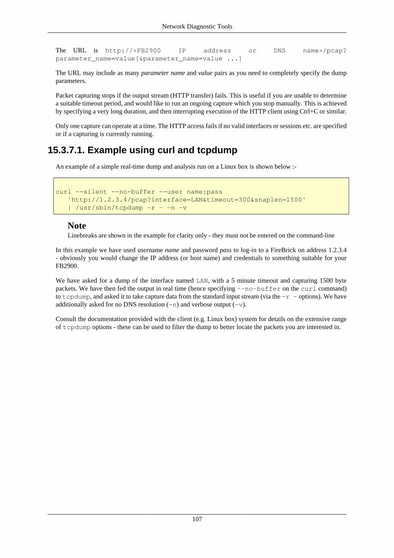
Network Diagnostic Tools
107
The URL is http://<FB2900 IP address or DNS name>/pcap?parameter_name=value[¶meter_name=value ...]
The URL may include as many parameter name and value pairs as you need to completely specify the dumpparameters.
Packet capturing stops if the output stream (HTTP transfer) fails. This is useful if you are unable to determinea suitable timeout period, and would like to run an ongoing capture which you stop manually. This is achievedby specifying a very long duration, and then interrupting execution of the HTTP client using Ctrl+C or similar.
Only one capture can operate at a time. The HTTP access fails if no valid interfaces or sessions etc. are specifiedor if a capturing is currently running.
15.3.7.1. Example using curl and tcpdump
An example of a simple real-time dump and analysis run on a Linux box is shown below :-
curl --silent --no-buffer --user name:pass 'http://1.2.3.4/pcap?interface=LAN&timeout=300&snaplen=1500' | /usr/sbin/tcpdump -r - -n -v
NoteLinebreaks are shown in the example for clarity only - they must not be entered on the command-line
In this example we have used username name and password pass to log-in to a FireBrick on address 1.2.3.4- obviously you would change the IP address (or host name) and credentials to something suitable for yourFB2900.
We have asked for a dump of the interface named LAN, with a 5 minute timeout and capturing 1500 bytepackets. We have then fed the output in real time (hence specifying --no-buffer on the curl command)to tcpdump, and asked it to take capture data from the standard input stream (via the -r - options). We haveadditionally asked for no DNS resolution (-n) and verbose output (-v).
Consult the documentation provided with the client (e.g. Linux box) system for details on the extensive rangeof tcpdump options - these can be used to filter the dump to better locate the packets you are interested in.

108
Chapter 16. VRRPThe FB2900 supports VRRP (Virtual Router Redundancy Protocol), which is a system that provides routingredundancy, by enabling more than one hardware device on a network to act as a gateway for routing traffic.Hardware redundancy means VRRP can provide resilience in the event of device failure, by allowing a backupdevice to automatically assume the role of actively routing traffic.
16.1. Virtual RoutersVRRP abstracts a group of routers using the concept of a virtual router, which has a virtual IP address. The IPaddress is virtual in the sense that it is associated with more than one hardware device, and can 'move' betweendevices automatically.
The virtual IP address normally differs from the real IP address of any of the group members, but it can be thereal address of the master router if you prefer (e.g. if short of IP addresses).
You can have multiple virtual routers on the same LAN at the same time, so there is a Virtual Router Identifier(VRID) that is used to distinguish them. The default VRID used by the FB2900 is 42. You must set all devicesthat are part of the same group (virtual router) to the same VRID, and this VRID must differ from that usedby any other virtual routers on the same LAN. Typically you would only have one virtual router on any givenLAN, so the default of 42 does not normally need changing.
NoteYou can use the same VRID on different port groups without a clash in any way in the FB2900.However, you cannot use the same VRID on different VLANs on the same port group, as the internalswitch in the FB2900 will only track the MAC address to one port at a time. You may also findsome switches and some operatings systems do not work well and get confused about the same MACappearing on different interfaces and VLANs. As such it is generally a good idea to avoid doing thisunless you are sure your network will cope. i.e. use different VRIDs on different VLANs.
At any one time, one physical device is the master and is handling all the traffic sent to the virtual IP address.If the master fails, a backup takes over, and this process is transparent to other devices, which do not need tobe aware of the change.
The members of the group communicate with each other using multicast IP packets.
The transparency to device failure is implemented by having group members all capable of receiving trafficaddressed to the same single MAC address. A special MAC address is used, 00-00-5E-00-01-XX, whereXX is the VRID or VRRPv2, and 00-00-5E-00-02-XX for VRRPv3.
The master device will reply with this MAC address when an ARP request is sent for the virtual router's IPaddress.
Since the MAC address associated with the virtual IP address does not change, ARP cache entries in otherdevices remain valid throughout the master / backup switch-over, and other devices are not even aware that theswitch has happened, apart from a short 'black-hole' period until the backup starts routing.
When there is a switch-over, the VRRP packets that are multicast are sent from this special MAC, sonetwork switches will automatically modify internal MAC forwarding tables, and start switching traffic to theappropriate physical ports for the physical router that is taking up the active routing role.
Note
You can disable the use of the special MAC if you wish, and use a normal FireBrick MAC. However,this can lead to problems in some cases.

VRRP
109
16.2. Configuring VRRPVRRP operates within a layer 2 broadcast domain, so VRRP configuration on the FB2900 comes under thescope of an interface definition. As such, to set-up your FB2900 to participate in a Virtual Router group,you need to create a vrrp object, as a child object of the interface that is in the layer 2 domain wherethe VRRP operates.
16.2.1. Advertisement Interval
A master indicates that it still 'alive' by periodically sending an advertisement multicast packet to the groupmembers. A failure to receive a multicast packet from the master router for a period longer than three times theadvertisement interval timer causes the backup routers to assume that the master router is down.
The interval is specified in multiples of 10ms, so a value of 100 represents one second. The default value, if notspecified, is one second. If you set lower than one second then VRRP3 is used by default (see below). VRRP2only does whole seconds, and must have the same interval for all devices. VRRP3 can have different intervalson different devices, but typically you would set them all the same.
The shorter the advertisement interval, the shorter the 'black hole' period, but there will be more (multicast)traffic in the network.
Note
For IPv6 VRRP3 is used by default, whereas for IPv4 VRRP2 is used by default. Devices have tobe using the same version. IPv4 and IPv6 can co-exist with one using VRRP2 and the other VRRP3.Setting the same config (apart from priority) on all devices ensures they have the same version.
16.2.2. Priority
Each device is assigned a priority, which determines which device becomes the master, and which devicesremain as backups. The (working) device with the highest priority becomes the master.
If using the real IP of the master, then the master should have priority 255. Otherwise pick priorities from 1to 254. It is usually sensible to space these out, e.g. using 100 and 200. We suggest not setting priority 1 (seeprofiles and test, below).
16.3. Using a virtual routerA virtual router is used by another device simply by specifying the virtual-router's virtual IP address as thegateway in a route, rather than using a router's real IP address. From an IP point-of-view, the upstream device iscompletely unaware that the IP address is associated with a group of physical devices, and will forward trafficto the virtual IP address as required, exactly as it would with a single physical gateway.
16.4. VRRP versions
16.4.1. VRRP version 2
VRRP version 2 works with IPv4 addresses only (i.e. does not support IPv6) and whole second advertisementintervals only. The normal interval is one second - since the timeout is three times that, this means the fastest abackup can take over is just over 3 seconds. You should configure all devices in a VRRP group with the samesettings (apart from their priority).

VRRP
110
16.4.2. VRRP version 3VRRP version 3 works in much the same way, but allows the advertisement interval to be any multiple of 10ms(1/100th of a second). The default interval is still 1 second, but it can now be set much faster - so although thetimeout is still 3 times the interval, this means the backup could take over in as little as 30ms.
VRRP3 also works with IPv6. Whilst IPv4 and IPv6 VRRP are completely independent, you can configureboth at once in a single vrrp object by listing one or more IPv4 addresses and one or more IPv6 addresses.
VRRP3 is used by default for any IPv6 addresses or where an interval of below one second is selected. It canalso be specifically set in the config by setting the attribute version3 to the value "true".
Caution
If you have devices that are meant to work together as VRRP but one is version 2 and one is version 3then they will typically not see each other and both become master. The FB2900's VRRP Status pageshows if VRRP2 or VRRP3 is in use, and whether the FireBrick is master or not.
16.5. CompatibilityVRRP2 and VRRP3 are standard protocols and so the FB2900 can work alongside other devices that supportVRRP2 or VRRP3.
Note that the FB2900 has non-standard support for some specific packets sent to the VRRP virtual addresses.This includes answering pings (configurable) and handling DNS traffic. Other VRRP devices may not operatein the same way and so may not work in the same way if they take over from the FireBrick.

111
Chapter 17. VoIP
17.1. What is VoIP?Voice over IP (VoIP) is simply a means of carrying voice (telephone calls) over Internet Protocol (the Internet).Instead of using pairs of wires to carry the signal electrically, the sound is sampled and converted to a sequenceof bytes. This is normally what is done in the telephone exchange before the data is sent over the telephonenetwork. The key difference with VoIP is that the bytes are placed in packets, typically 20ms long, and theseare sent via Internet Protocol. Unlike the telephone network, IP can cause packets to be delayed, lost or evencopied. It is the job of the receiving end to cope with this and produce the audio again for the recipient to hear.
The end result is that telephone calls can be made over the Internet. This can cause confusion as this is oftenseen simply as free calls. Apart from costs for Internet traffic, this is indeed true where calls do not involve thetraditional telephone network and you control both ends, but typically you will need to subscribe to a carrierwho can route calls to and from the traditional telephone network.
The FB2900's role in this it to handle the IP packets used for VoIP. It does not get involved in convertingsound to, or from, packets of data, but in passing those packets of data between VoIP devices and carriers. Theprotocol involves complex sequences of messages for control and authentication which the FB2900 handles.
17.2. Registration and ProxiesOne of the common confusions with SIP/VoIP is the way registrations work.
17.2.1. Registrar
A SIP device can register with a service, e.g. with the FB2900, or with a SIP carrier. This is like logging inand means that incoming calls are then sent to the device. The device will renew the registration periodicallyto stay logged in, and if it fails to do this then incoming calls will fail.
This process uses a username and password for security. Obviously you also have to say where to register, theproxy specifies IP address or host name of the SIP service with which you are registering, and the registrardefines the hostname to use in the registration.
This process works well if the service does not have a fixed idea of where you are, which is normally the casefor SIP handsets. Even on a local network the IP of the handset will normally be dynamically allocated withDHCP, and for a SIP carrier the IP could be anywhere in the world.
NoteIt is possible to have a VoIP carrier that does have a pre-set idea of where calls are to be sent, andsends the calls without registration. In this case there is no registration process but the handset/devicehas to be able to accept calls from the carrier. Again, a username and password are used for security,but this time it is the device checking the credentials of the carrier.
17.2.2. Proxy
To make an outgoing call via a SIP carrier you have to send the call details to a proxy. In the case of the FB2900acting as the carrier, the same address is used for registrar and proxy.
The process uses a username and password in much the same way as registration, and they are usually thesame details. This checks that the device is allowed to make the calls, and allows the right person to be billedfor the call.
VoIP
112
TipYou can have a case of incoming calls working and not outgoing, which means registration has workedbut somehow you have incorrect proxy details. The other way around, where outgoing calls work andincoming do not would mean the registration is not working, but the proxy details are correct. Thelogging options can be very useful to help diagnose problems.
17.3. Home/office phone systemThe FB2900 can be used as an office phone system (PABX) which allows you to connect a number of handsets(telephones) in your office, and make and receive calls from the telephone number using a subscription to acarrier over the Internet.
Traditionally a PABX would connect to one or more telephone lines, whether analogue or ISDN, and to anumber of telephone handsets. The PABX would allow internal calls (handset to handset) and external calls toand from the external phone lines. It would have features like busy lamp fields and hunt groups.
The FB2900 does the same job as a traditional PABX, but using IP.
• Instead of phone lines or ISDN, the external calls are handled via an Internet Provider (ISP) and a VoIPcarrier. This can allow many calls and phone numbers to be used, and is generally a lot more scalable andflexible than traditional phone lines.
• Instead of internal phone wiring to connect telephone handsets, the FB2900 connects to handsets via theoffice LAN network. This can be the same network as used for PCs, or separate, or segregated using VLANs.
• Instead of analogue phones, or special system phones for a PABX, the FB2900 works with any standard SIPVoIP phones. There are a wide range of phones available in a range of price brackets. The FireBrick hasbeen tested well with snom phones, including features such as busy lamp field lights and buttons.
• The FB2900 scales well to support hundreds of phones in an office without needing extra FireBrick hardware.This makes the FireBrick a much more scaleable and economical PABX solution than traditional systems.
• It is possible to configure remote handsets, e.g. for home workers, connecting over the Internet.
The FB2900 can work with trunk carriers where one login/connection is used to carry many calls to differentnumbers, or it can appear to the carrier(s) as multiple separate VoIP devices, or any combination. This allowsthe FB2900 to be used with almost any VoIP carrier.
17.4. Network Address TranslationNetwork Addres Translation (NAT) is common on many Internet connections in homes and offices. It meansthat the office uses private IP addresses (e.g. 192.168.1.1) and these are mapped (translated) to one externaladdress.
NAT is known to cause a lot of problems with a wide variety of applications and protocols. One of those thatsuffers a lot from the problems of NAT is VoIP. There are, sometimes, ways of making this work, but it usuallya compromise of some sort and prone to problems.
The FB2900 provides some key ways to tackle the issues of NAT.
• An FB2500/FB2700 can be used as a gateway device in a home or office - using PPPoE to connect to theInternet. This means the FireBrick has a real external IP address without NAT. The FireBrick can thenconnect to SIP handsets on the LAN using private IP addresses. The FireBrick provides a gateway for VoIPwith no NAT implications.
NoteSome ISPs may use Carrier Grade NAT (CGNAT), and so a real IP address may involve additionalcost.

VoIP
113
• The FireBrick can make use of the current Internet Protcol (IPv6). At present there are few carriers andhandsets that work with IPv6, but this is improving all of the time. IPv6 avoids the need for NAT. TheFireBrick acts as a media gateway which makes firewalling rules simple even when using IPv6, and allowsIPv4 and IPv6 devices to interwork with no problems.
• The FireBrick, when acting as a call server outside of any NAT connected telephones, can handle cases wheredevices are behind a simple port mapping NAT which has a timeout of at least 60 seconds. It recognisesREGISTER and INVITE requests that appear to be behind NAT and will treat the requester IP/port as thecontact rather than the stated contact in the message. At RTP level it will send all audio to the same IP andport from which it is received rather than the endpoint defined in the SDP. Registrations that seem to be fromNAT connections will receive a null UDP packet at approximately 60 second intervals to keep the controlsession open on the NAT router. This is not foolproof but works in most cases with simple NAT gateways(including where a FireBrick is doing the NAT). It obviously also works where a NAT device is doing fullALG and changing the control messages and RTP accordingly.
17.5. Number planWhen setting up an office phone system you need to consider extension numbers. These are short numbers,typically 2, 3, or 4 digits used to call other telephones on the same system. You can use these numbers to callother extensions and, importantly, use them in configuration of hunt groups and so on, making the config easierto understand.
In addition to an extension number you would normally set a ddi (Direct Dial In) full phone number for eachtelephone. This is not a requirement and you can just use internal numbers for phones if you prefer.
It is a good idea to make a clear plan for how you will allocate the internal numbers, especially if you havea corresponding block of real phone numbers. Consider which are nice numbers you may want to publishfor some reason, and which could be obvious mis-dials. Maybe group extensions by department, etc. Alwaysassume you will need more numbers later so make a plan that allows for expansion.
TipIt is a good idea to get a block of telephone numbers from your carrier, and use extension numbersthat are the last 2 or 3 digits from that block. That means everyone knows the full phone number forany extension. Most carriers can provide a block of numbers. You can then configure these as the DDI(Direct Dial In) numbers for each telephone.
NoteExtension numbers can be any length you like. They should be kept short so they are not confusedwith local telephone numbers and are easy to dial. There is no need to dial 9 for an outside line asVoIP phones send the whole number when you dial. The only special cases are emergency numbers(112 and 999 by default) which cannot be used as extension numbers.
NoteDDI (Direct Dial In) telephone numbers must be entered in the full international format. This isa plus (+) then the country code, and area code, and number. e.g. +441234567890 which iscountry code 44 for UK, area code 1234 and local number 567890. In the UK you would dialthis as 01234567890. Note that UK numbers have no 0 in front of the area code when quoted ininternational format.
17.6. Telephone handsetsAny VoIP handset which supports SIP will normally work with the FB2900. Most makes of handset actuallyallow multiple identities on the handset so it can appear as multiple handsets to one or more phone systems,but a typical installation will not normally need more than on identity per handset.
VoIP
114
On the handset you will need to set a registrar and/or proxy which is usually either a host name or an IP address.This will need to refer to the FB2900's address.
The handset will also have some form of login or username and a password. Typically you would use theextension number or DDI as the username, but in an office PABX you may want people's names as the username.
On the FB2900 you add a telephone configuration object (VoIP users) for each telephone, specifying a usernameand password. If the handset will need to connect from somewhere that is not on the local network (LAN) thenyou also need to set local-only to false.
NoteThe telephone is identified by the name field matching the SIP request. However, if this is not matchedand the telephone has sent a pre-challenge Authorization header to indicate the username itis using then this will be matched instead.
You also need to set the extn and ddi for the phone. Also, in order to make external calls you need to selecta carrier to use.
TipThere are a number of other settings which can be useful. The display-name will show the caller nameon internal calls. You can also limit the number of concurrent calls. Some other features are describedin corresponding sections below.
The VoIP status page shows the active registrations from handsets.
TipThe log-register and log-register-debug settings can provide a lot of information aboutregistrations and help diagnose any problems.
17.7. VoIP call carriersA VoIP carrier is a service provider that can accept outgoing calls, and route incoming calls. Typically a VoIPcarrier is expecting a handset to register with the carrier, and will then send calls to the registered device. It isalso possible for a VoIP carrier to send calls to the FB2900 using a fixed pre-set configuration.
To set up a VoIP carrier where the FB2900 registers with the carrier you need to specify the registrarattribute. This can be a host name or IP address. You also need to specify the username and password. Forincoming calls you need to specify the extn that is logically dialled when a call comes in from this carrier -this can be the extension number of a telephone or hunt group.
To set up a VoIP carrier for outgoing calls you need to specify the proxy. This can be a host name or IPaddress. You also need to specify the username and password.
You can define the carrer to use for outgoing calls on a per telephone basis, and also for hunt groups (where thegroup calls an external number). You can also define a default carrier if none is otherwise specified. A backupcarrier can also be defined which is used if the call fails via the selected carrier.
For a carrier that sends calls to the FB2900 without registration, you will need to know how the FireBrickrecognises the call is from a carrier.
For a start, all carriers considered have the allow attribute, if present, checked agasint the source IP, and ifnot allowed the carrier is excluded from any consideration.
Also, if there is an Authorization header with a username, only carriers with a matching user name or nousername set will match.
Then the following tests are done to find a carrier match, finding the first.

VoIP
115
• The request is unauthorized, and has a SIP target or To header of a registered contact from an outgoingregistration from the carrier (can be from any allowed IP).
• The SIP target matches exactly one of the to entries in a carrier, or if a blank to attribute and theAuthorization username matches the username.
• The SIP target, or if that has no host part, the To header host part, prefixed with @, matches one of the toentries in a carrier.
Once a carrier is picked, if it has a password (and was not to a registered contact), the password must match,after sending a challenge if necessary.
NoteThe carrier may send a pre-challenge Authorization header to indicate the username it is using- in such case the carrier selection will only match entries that have that username set and can matchentries with no to attribute defined. When a FireBrick attempts an authenticated call it can send sucha pre-challenge Authorization header.
An incoming carrier will usually relate to a specific extn which is what is called when a call comes in. Youcan leave this unset and route based on called ddi or you can set the extn including X characters in placeof the digits sent with the call as the dialled number. These are taken from the right hand end of the diallednumber, so if 0134567890 is what was called, 1XX would be extn 190. This makes it easy to define a trunkcarrier for incoming calls.
17.8. Hunt groupsThe basic idea of a hunt group is simple: It has a number, which when called causes a number of extensionsto be rung, perhaps in order, to hunt for someone to take the calls. In practice there are a number of optionsas to how the hunt group works.
Creating a hunt group involves picking an extension number. In the same way as a telephone user is set up,you can also set a display name and DDI number.
The main set of numbers that the hunt group will call is specified in the ring attribute. By default this causesall of the numbers listed to be rung at once.
TipYou can list internal extension numbers for ring and overflow lists, or you can include full DDIsor even external phone numbers to be included.
TipIt is possible to set a wrap up time on a phone (a per-telephone setting), which stops group calls ringingthe phone for a period of time after the call ends. This is to allow notes to be made, etc, after the call.
17.8.1. Ring TypeYou can specify a different type of ringing rather than just ringing all phones at once:
Table 17.1. Ring Type
Type Operation
all Ring all phones at once
cascade Ring phones in a sequence, but do not stop ringing existing phones when startingto ring the next one

VoIP
116
sequence Ring phones in a sequence, ringing one phone at a time
You can set the timing used for calls to progress through the list of phones.
17.8.2. Ring orderWhen not ringing all phones at once, you can control the order they are rung:
Table 17.2. Ring Order
Order Operation
strict Use the order you have listed the phones, starting from the first phone each timethe hunt group is called
random Use a random order
cyclic Ring in order that you have listed, but continue that pattern on the next call ratherthan starting again
oldest Consider how recently a phone has been in use, and ring the oldest first. This onlyworks with internal phones, not external numbers which are always rung last
17.8.3. OverflowYou can specify an overflow set of phone numbers to be rung if the call has been ringing too long. You canconfigure how long is too long. When you get to overflow time all phones are rung including the overflow list.
17.8.4. Out of hoursYou can set a profile on the hunt group, which is typically a time and day based profile. When the profileis off the hunt group does not work, or you can set an alternative ring group to apply when out of profile. Thiscan cascade through out of profile groups. You can, instead, set an alternative ring list to use when out ofhours number.
TipThe ring list and overflow list cannot use the numbers of other hunt groups, but the out of hours numbercan be another hunt group number.
17.9. Call pickup/stealBy default it is possible to pick-up a ringing call to a telephone or hunt group by dialling a prefix (default *)and the extension number of the telephone or hunt group. This stops the call ringing the phone or hunt groupand connects it to the phone that dialled the pick up code.
TipYou can restrict which phones are allowed to pick up or steal a call in the telephone and hunt groupconfiguration.
Using the same code you can also steal an active call from a telephone. This hangs up the telephone and movesthe call to the phone that dialled the code.
TipCall stealing is useful as a sort of reverse call transfer which works well in an open office. Someonecan say "I have a call for you on 406" and you can dial *406 to steal the call from them. This isquicker, saves them asking your extension number, and avoids putting the caller on hold. It is muchlike key and lamp systems where someone might say "There is a call for you on line 3".

VoIP
117
17.10. Busy lamp fieldBusy lamp fields are normally a light and button on a phone. The snom phones can have BLF enabled.
In your handset you set up BLF by specifying an extension number of a handset to be monitored. The busylight will typically be on solidly when in a call, or flashing when there is an incoming call ringing.
You can also subscribe to a hunt group using its extension number, this shows flashing when the hunt grouphas a ringing call.
TipPressing a button next to the busy light will usually call that extension. You can configure themonitored extension prefixed with the call pick up code (default *) to make the button a pickup/stealbutton. This is ideal to pick up a ringing call for a telephone or hunt group when the light is flashing.
NoteYou can restrict who is allowed to subscribe to a phone or hunt group in the configuration.
17.11. Using RADIUSRADIUS can be used to allow new handsets to be registered dynamically without individual configurationby using RADIUS authentication to an external RADIUS server. RADIUS is also used to make call routingdecisions.
RADIUS accounting can be used to log calls as they start and end to an external RADIUS server.
NoteRADIUS for VoIP is only available on a fully-loaded model.
TipYou have to configure each of the radius functions in the VoIP config - leaving the radius setting unsetwill disable use of RADIUS for that feature. There are separate configuration settings for register,call and cdr.
17.11.1. RADIUS accountingRADIUS accounting logs each call leg, so a typical call has an incoming and outgoing leg.
• A RADIUS START message is sent when the call leg is created.
• A RADIUS INTERIM update is sent if/when the call connects (i.e. status 200).
• A RADIUS STOP message is sent when the call ends, even if it did not connect.
An interim update includes a call duration which is the time spent ringing. A final (stop) message contains acall duration which is the time from the connection of the call.
17.11.2. RADIUS authenticationRADIUS authentication is used for any requests with Authorization header, such as REGISTER, INVITE,REFER, SUBSCRIBE, OPTIONS etc. The Digest-Method is always included to indicate a VoIP request andidentify the type of request.
You can have a RADIUS authentication before the FireBrick challenges the requestor setting the radius-challenge settings, allowing a RADIUS challenge response to customise the challenge. This also happens

VoIP
118
for a non local request where the user is not recognised as a local telephone user. Otherwise the FB2900 willsend a challenge automatically and only send a RADIUS authentication when the authenticated message isreceived. This also happens if an Authorization header is presented without a response value.
TipFor an unauthenticated request you can respond with an Access Challenge including the paramatersto challenge, but any attributes you omit will be completed automatically, so you can simply respondwith an empty challenge to confirm the FB2900 is to go ahead and do the challenge itself.
For REGISTER an accept response can include a Called-Station-Id attribute to define the registered connectionas a tel:number URI for call routing. Without this, the registration is not logged on the FB2900 and it isassumed the RADIUS server will record where to send calls based on the registration. The SIP-AOR AVP inthe access request provides the Contact URI, and can be used in the reply to cause a 302 redirect response toa specified contact.
• An access request is sent to approve any SIP request such as REGISTER, SUBSCRIBE, OPTIONS, etc.
• An access request is sent to make call routing decision for INVITE and REFER.
• An access request is sent to make a call routing decision when a 3xx response is received from a connectionbeing made to a telephone. Acct-Terminate-Cause specifies the redirect code, e.g. 301, 302.
Access requests are made even when the request is coming from an locally configured telephone. In such casesthe telephone must also pass validation against a locally configured password (if present). To identify suchrequests, the User-Name is the configured name (or extn or ddi) of the telephone user, and the Chargeable-User-Identity attribute is set based on the configured CUI.
Access requests are made even when from a recognised carrier. In such case the carrier is validated by theFireBrick directly, and then the access request is made to decide call routing. To identify such requests, theUser-Name is the configured name of the carrier prefixed with an @ character.
NoteIn the case of a telephone user, any @ charaters at the start of the name are removed so that it cannotbe confused with a carrier.
NoteA call can come from anywhere. An unknown request from a non local IP will send a RADIUS requestbefore challenging the requestor so that the RADIUS server can decide if it is to be challenged or not.An Access reject with no message attribute will not send any error to a non local IP requestor - adda message to force this.
17.11.2.1. Call routing by RADIUS
To understand how call routing works you need to understand how call legs work. A call leg is a connection to orfrom the FB2900 to another SIP device. It could be a SIP carrier or a telephone. Typically there is an incomingcall leg from a carrier or a phone, which needs to be authenticated, and then a call routing decision is made.
An Access Accept response can then contain the call routing attributes. This causes one or more outgoing calllegs to be created. These would typically be ringing telephones. Once one of these legs answers the others arecancelled and the two legs are connected together to form a call. The purpose of the routing attributes is tocreate these outgoing call legs, and to set up attributes such as CDRs and call recording.
Each call leg has a CLI (calling number), a Dialled number, a display Name, a number of CDR records (eachof which have CDR and Dialled as well), and finally a number of email addresses for call recording.
The response attributes are processed in order. Initially the last call leg is the originating call. When a newoutgoing leg is added, that becomes the current call leg.

VoIP
119
Table 17.3. Access-Accept
AVP No. Usage
Calling-Station-Id 31 Replaces CLI of current call leg.
Called-Station-Id 30 Replaces Dialled number of current call leg.
User-Name 1 Replaces the Name of the current call leg.
Filter-Id 11 Adds a call recording email address to the current call leg.
Chargeable-User-Identity
89 Adds a CDR record with this CUI, and current CLI and Dialled attributes tothe current call leg.
SIP-AOR 121 Creates a new outgoing call leg. See below for formats
An outgoing call leg is created for each SIP-AOR entry, and it can be in one of the following formats. Each ofthese can also include a number of digits and a + symbol at the start which specifies a delay before attemptingto connect the outgoing leg.
• number@carrier which causes a call via a known carrier. The part after the @ is the name of the carrier inthe config. The Dialled number is set to the number specified, and the CLI is set from the originating call.
• tel:number which causes a call via a registered telephone. The Dialled number is set to the number specified,and the CLI is set from the originating call.
• sip:uri which causes a call via a an arbitrary SIP URI. The Dialled number and CLI are set from the originatingcall. This format allows sip:number@host and sip:user:pass@host and also sip:user:pass@host/number.This final version makes a call using the sip:number@host target but authenticates using user and pass.
• NNN a custom response code, such as 404, 500, etc, can be provided to indicate that the call is actually tobe rejected.
• 3NN:URL A 3NN response code can be used, where 3NN is then replaced by sip: in the contact in theresponse. This feature is somewhat experimental.
TipIf the originating call leg is incoming and not get been connected, a single SIP-AOR response can beprovided in the format of a 3 digit response code, or 3xx:uri where 3xx is the response code (e.g. 302)and is replaced by sip: and used as a Contact header in a 3xx response. Redirect only works on somecarriers/phones and serves to redirect the incoming call away from the FB2900.
17.12. Call recordingThe FB2900 supports call recording by teeing off the two way audio from a call leg and sending to a SIPendpoint. The SIP endpoint will then record the call and handle it in any way you wish.
The recording is controlled by setting an email address on a call leg. This can be configured for telephone usersand set to automatically record incoming one, outgoing only, or all calls. You can also set this on a hunt groupto record all incoming calls to the hunt group (attaching the recording to the calling leg).
The recording server can be any SIP endpoint, such as an asterisk box. A linux based call recording app isavailable to FireBrick customers for this purpose, and some VOIP carriers may offer this as a service.
TipIf the SIP endpoint supports stereo A-law then the recording is made in stereo with each side of theconversation on a channel. The supplied call recording app makes stereo A-law WAV files, and canbe configured to send these by email as each call ends.

VoIP
120
17.13. Voicemail and IVR servicesVoicemail is still in development. The FB2900 will simply pass the call to a voicemail server via SIP. Thiscould be a local device on the network, or a service provided by a carrier. We will include a software packageto run on a linux box that will save the recording.
TipMost VoIP carriers provide voicemail
17.14. Call Data RecordsA Call Data Record (CDR) is a record that is used for charging for a call. It consists of the following whichare shown in a comma separated list.
• Start time when call connected (UTC with milliseconds), or if not connected then when call created
• Duration of ringing (seconds and milliseconds)
• Duration of call (seconds and milliseconds), or minus and call status if call not connected
• Call Record Data
Where the CDR is created based on the presence of a cui setting in the configuration, the Call Record Dataconsists of the following fields. Where RADIUS is used the Call Record Data is simply the data provided byRADIUS.
• Chargeable User Identiy (the content of the cui setting)
• Dialled number
• Calling Line Identity
The CUI is just a string of characters. It can be set on a telephone user, but defaults to ddi, exten or name, ifnot set. It is typically the telephone number that should pay for the call being made.
In a simple example of a telephone calling an external number, the call comes in (inbound leg) and an outgoingcall is made to the carrier (outbound leg). A CDR record is attached to the outbound leg with the telephone'sCUI, and the corresponding CLI and dialled number used. When the call connects the start time is set on theCDR. At the end of the call the CDR record is written out. CDR records can be logged (e.g. syslog) and sendby RADIUS accounting. RADIUS accounting also carries details of each call leg (start, interim and stop), andthe CDR records are contained in the final RADIUS STOP message for the call, so only in one record.
There are more complex examples, such as A calls B, and B diverts to C. When a call is diverted or transferred,the CDR for that outbound leg is moved to the new outbound leg along with any CDR for that outbound leg.This means that, in this example, you get two final CDRs, one for A to B, and one for B to C, each startingwhen the call connected and having the same duration.
For a transfer, e.g. A calls B, B places on hold and calls C, then B transfers call, you have the same situation,but the start times and duration of the two parts are not the same.
This stacking of CDRs is important for call billing. In these examples A only expects to pay for a call to B(which may even be free if an internal call). But B expects to pay for the call to C because they diverted ortransferred the calls.
A CDR can be associated with an incoming call leg, this is normally set by RADIUS, or by giving a carrier acui setting. This is sticky and stays with the calling leg, and is logged when the calling leg ends even if the calldid not connect. Otherwise the CDR is only logged if it connects.

VoIP
121
NoteRADIUS CDR are only available on a fully-loaded model. Log (e.g. syslog) CDRs are available onall models.
17.15. Technical detailsThe FireBrick operates according to well established technical standards within specific design constraintswhich allow it to operate efficiently handling thousands of calls.
• SIP/2.0 UDP control messages using IPv4 or IPv6 are supported up to approximately 1900 bytes (fragmentedif necessary).
• The FireBrick always acts as an audio media endpoint, i.e. it is always in the media path. This minimises callrouting and firewalling issues. The FireBrick uses the same IP for media and control messages on each call.
• The FireBrick always acts as a SIP protocol endpoint and not as a relaying proxy. This minimisesincompatibility between end devices being a party to a call as they do not see each others protocol messages.
• Only RTP audio using A-law 20ms is supported. This is generally compatible with all carriers and devicesand provides high quality audio.
• Out of band DTMF is accepted using SIP INFO or RFC2833. DMTF can be sent using RFC2833 or generated-law in-band audio.
• Error responses to REGISTER/INVITE from non local devices are not normally sent - this is against the SIPprotocols but avoids issues with port scanning systems looking for VoIP platforms. This can make diagnosisof incorrect settings harder.
The design is intended to work with all common VoIP handsets and carriers. If you experience any difficultywith a carrier or a VoIP device, please contact the FireBrick support team, ideally with a full debug log.
TipIt is possible to set different source IP addresses to be used per carrier - obviously, to work, thesehave to be IP addresses that the FireBrick has, but it can be useful to force registration via specificaddresses. It is also possible to define a default IPv4 and IPv6 source address to be used for messagesthat can be authenticated, thus allowing different source addresses to be used for messages to which achallenge must be sent and those that do not expect a challenge. This can be useful when dealing withremote boxes that have to decide on a challenge based on source address.
17.16. Custom tonesThe configuration also allows customised tones to be generated. You can replace these with your own versions.
The format for a tone is either a single tone or a series of duration@tone sections. In a sequence you canuse duration for a period of silence. A duration is a number and then ms and a tone is a frequency orfrequency+frequency for mixing two tones. Each frequency is a number of Hz and can have a volume suffixwhich is - and a number if dB. The tone can be followed by ^ if you want it to be shaped (rise at start andfall at end).
Whilst internally only the basic tones for silence, progress, ring, queue, hold, wait, you can configure the useof tones for various cases when no audio is present and calling a specific carrier.
Table 17.4. Default tones
Tone Plan
silence 100ms

VoIP
122
progress 1000ms 1000ms@400Hz-3dB+450Hz-3dB 1000ms
ring 1000ms 400ms@400Hz-3dB+450Hz-3dB 200ms 400ms@400Hz-3dB+450Hz-3dB1000ms
queue 700ms 400ms@400Hz-3dB+450Hz-3dB 200ms 400ms@400Hz-3dB+450Hz-3dB 200ms400ms@400Hz-3dB+450Hz-3dB 700ms
busy 375ms@400Hz 375ms
hold 100ms@400Hz-3dB+450Hz-3dB 200ms 100ms@400Hz-3dB+450Hz-3dB 2600ms
wait 2600ms 100ms@400Hz-3dB+450Hz-3dB 200ms 100ms@400Hz-3dB+450Hz-3dB
close-encounter 1000ms 300ms@588Hz^ 300ms@654Hz^ 400ms@524Hz^ 600ms@262Hz^1000ms@392Hz^ 1000ms
bbc 50ms 345ms@122Hz 35ms 300ms@525Hz 2000ms
1000Hz 1000Hz
beep 200ms 200ms@800Hz 200ms
pi 350Hz-3dB+440Hz-3dB
spi 750ms@350Hz-3dB+440Hz-3dB 750ms@440Hz-3dB
pet 400ms@400Hz-6dB 350ms 225ms@400Hz 525ms
sct 200ms@400Hz 300ms@1004Hz
cnai 100ms@400Hz
sit 330ms@950Hz 5ms 330ms@1400Hz 5ms 330ms@1800Hz
cwi 100ms@400Hz 5000ms
scwi 30ms@400Hz 10ms 30ms@400Hz 6000ms
pt 125ms@400Hz 125ms
ct 20000ms@1400Hz
st 200ms@400Hz 400ms 2000ms@400Hz 400ms
TipAccessing a url on the FireBrick of /voip/ring.wav serves a WAV format of the tone. You cantest tones using a URL like /voip/tone.wav?100ms@1000Hz+200ms@2000Hz but ensureyou URL escape the query string.

123
Chapter 18. BGP18.1. What is BGP?
BGP (Border Gateway Protocol) is the protocol used between ISPs to advise peers of routes that are available.Each ISP tells its peers the routes it can see, being the routes it knows itself and those that it has been advisedby other peers.
In an ideal world everyone would tell everyone else the routes they can see; there would be almost noconfiguration needed; all packets would find the best route accross the Internet automatically. To some extentthis is what happens between major transit providers in the Internet backbone.
In practice things are not that simple and you will have some specific relationships with peers when using BGP.For most people there will be transit providers with which you peer. The FB2900 cannot take a full table (mapof the whole Internet) from a transit provider so you would typically have a default route to them. You canadvise the transit provider of your own routes for your own network so that they can route to you, and they telltheir peers that they can route to you via that provider. This only works if you have IP address space of yourown that you can announce to the world - unless you are an ISP then this is not commonly the case.
Even though IPv4 address space has already run out, it is possible to obtain IPv6 PI address space and an ASnumber to announce your own IPv6 addresses to multiple providers for extra resilience.
You can use BGP purely as an internal routing protocol to ensure parts of your network know how to route toother parts of your network, and can dynamically reroute via other links when necessary.
In most cases, unless you are an ISP of somesort, you are not likely to need BGP.
18.2. BGP Setup
18.2.1. OverviewThe FB2900 series router provides BGP routing capabilities. The FB2900 cannot handle a full table. The aimof the design is to make configurationm simple for a small ISP or corporate BGP user - defining key types ofBGP peer with pre-set rules to minimise mistakes.
CautionMisconfiguring BGP can have a serious impact on the Internet as a whole. In most cases your transitproviders will have necessary filtering in place to protect from mistakes, but that is not always the case.If you are an ISP and connect to peering points you can cause havoc locally, or even internationally,by misconfiguring your BGP. Take care and get professional advice if you are unsure.
18.2.2. StandardsThe key features supported are:-
• Simple pre-set configurations for typical ISP/corporate setup
• RFC4271 Standard BGP capable of handling multiple full internet routing tables
• RFC4893 32 bit AS number handling
• RFC2858 Multi protocol handling of IPv6
• RFC1997 Community tagging, with in-build support of well-known communities

BGP
124
• RFC2385 TCP MD5 protection
• RFC2796 Route reflector peers
• RFC3392 Capabilities negotiation
• RFC3065 Confederation peers
• RFC5082 TTL Security
• Multiple independent routing tables allowing independent BGP operations
• Multiple AS operation
18.2.3. Simple example setupA typical installation may have transit connections from which a complete internet routing table is received,peers which provide their own routes only, internal peers making an IBGP mesh, customers to which transitis provided and customer routes may be accepted. To make this set up simple the <peer> definition contains atype attribute. This allows simple BGP configuration such as:-
<bgp as="12345"> <peer as="666" name="transit1" type="transit" ip="1.2.3.4"/> <peer as="777" name="transit2" type="transit" ip="2.3.4.5 2.3.4.6"/\> <peer type="internal" ip="5.6.7.8"/\></bgp>
This example has two transit providers, the second of which is actually two peer IP addresses, and one internalconnection. Note that the peer AS is optional and unnecessary on internal type as it has to match ours.
The exact elements that apply are defined in the XML/XSD documentation for your software release.
18.2.4. Peer typeThe type attribute controls some of the behaviour of the session and some of the default settings as follows.
Table 18.1. Peer types
Type Meaning
normal Normal mode, no special treatment. Follows normal BGP rules.
transit Used when talking to a transit provider, or a peer that provides more than just their ownroutes. Peers only with different AS. The community no-export is added to imported routesunless explicitly de-tagged
peer Used when talking to a peer providing only their own routes. Peers only with different AS.The community no-export is added to imported routes unless explicitly de-tagged allow-only-their-as defaults to true
customer Used when talking to customers routers, expecting transit feed and providing their ownroutes Peers only with different AS allow-only-their-as defaults to true allow-exportdefaults to true The community no-export is added to exported routes unless explicitly de-tagged
internal For IBGP links. Peers only with same AS allow-own-as defaults to true
reflector For IBGP links that are a route-reflector. Route reflector rules apply Peers only with sameAS allow-own-as defaults to true

BGP
125
confederate For EBGP that is part of a confederation. Confederation rules apply Peers only with differentAS
ixp Must be EBGP, and sets default of no-fib and not add-own-as. Routes from this peer aremarked as IXP routes which affects filtering on route announcements. Only announced onEBGP not IBGP.
18.2.5. Route filteringEach peer has a set of import and export rules which are applied to routes that are imported or exported fromthe peer. There are also named bgp-filter which can be used as import-filters or export-filters.
The objects import and export work in exactly the same way, checking the routes imported or exported against aset of rules and then possibly making changes to the attributes of the routes or even choosing to discard the route.
Each of these objects contain:-
• Cosmetic attributes such as name, comment, and source.
• Route matching attributes allowing specific routes to be selected
• Action attributes defining changes to the route
• A continuation attribute stop defining if the matching stops at this rule (default) or continues to check furtherrules
The rules are considered in order. The first rule to match all of the matching attributes is used. If no rules matchthen the default actions from the import/export object are used.
In addition, the top level import/export has a prefix list. If present then this will limit the prefixes processed ata top level, dropping any that do not match the list without even considering the rules.
18.2.5.1. Matching attributes
The actual attributes are listed in the XML/XSD documentation for the software version. The main ones are:-
• A list of prefixes filters defining which prefixes to match
• There will be community tag checking and AS path checking in future
You can have a rule with no matching attribute which will always be applied, but this is generally pointless as nolater rules will be considered. If you want to define defaults then set them in the top level import/export object.
18.2.5.2. Action attributes
The actual attributes are listed in the XML/XSD documentation for the software version. The main ones are:-
• Adding specific community tags
• Removing specific community tags, including defaults added by the peer type.
• Dropping the route completely
• Changing the MED
• Changing the localpref
The logic works by creating a set of actions that are applied, and these are based on top level settings in thepeer (such as set-med) followed by the list of import or export named filters from which one matching actionis picked, and then followed by the peers indivdiual import and export rules from which one mathcing action
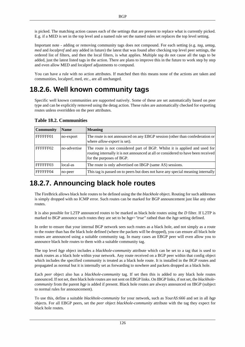
BGP
126
is picked. The matching action causes each of the settings that are present to replace what is currently picked.E.g. if a MED is set in the top level and a named rule set the named rules set replaces the top level setting.
Important note - adding or removing community tags does not compound. For each setting (e.g. tag, untag,med and localpref and any added in future) the latest that was found after checking top level peer settings, theordered list of filters, and then the local filters, is what applies. Multiple tag do not cause all the tags to beadded, just the latest listed tags in the action. There are plans to improve this in the future to work step by stepand even allow MED and localpref adjustments to compund.
You can have a rule with no action attributes. If matched then this means none of the actions are taken andcommunities, localpref, med, etc., are all unchanged.
18.2.6. Well known community tagsSpecific well known communities are supported natively. Some of these are set automatically based on peertype and can be explicitly removed using the detag action. These rules are automatically checked for exportingroutes unless overridden on the peer attributes.
Table 18.2. Communities
Community Name Meaning
FFFFFF01 no-export The route is not announced on any EBGP session (other than confederation orwhere allow-export is set).
FFFFFF02 no-advertise The route is not considered part of BGP. Whilst it is applied and used forrouting internally it is not announced at all or considered to have been receivedfor the purposes of BGP.
FFFFFF03 local-as The route is only advertised on IBGP (same AS) sessions.
FFFFFF04 no-peer This tag is passed on to peers but does not have any special meaning internally
18.2.7. Announcing black hole routesThe FireBrick allows black hole routes to be defined using the the blackhole object. Routing for such addressesis simply dropped with no ICMP error. Such routes can be marked for BGP announcement just like any otherroutes.
It is also possible for L2TP announced routes to be marked as black hole routes using the D filter. If L2TP ismarked to BGP announce such routes they are set to be bgp="true" rathed than the bgp setting defined.
In order to ensure that your internal BGP network sees such routes as a black hole, and not simply as a routeto the router than has the black hole defined (where the packets will be dropped), you can ensure all black holeroutes are announced using a suitable community tag. In many cases an EBGP peer will even allow you toannounce black hole routes to them with a suitable community tag.
The top level bgp object includes a blackhole-community attribute which can be set to a tag that is used tomark routes as a black hole within your network. Any route received on a BGP peer within that config objectwhich includes the specified community is treated as a black hole route. It is installed in the BGP routes andpropagated as normal but it is internally set as forwarding to nowhere and packets dropped as a black hole.
Each peer object also has a blackhole-community tag. If set then this is added to any black hole routesannounced. If not set, then black hole routes are not sent on EBGP links. On IBGP links, if not set, the blackhole-community from the parent bgp is added if present. Black hole routes are always announced on IBGP (subjectto normal rules for announcement).
To use this, define a suitable blackhole-community for your network, such as YourAS:666 and set in all bgpobjects. For all EBGP peers, set the peer object blackhole-community attribute with the tag they expect forblack hole routes.

BGP
127
It is unlikely you would want to announce a black hole route to an EBGP peer without an agreed tag as youwill be drawing traffic from them only to be discarded. If you want to do this, you have to specify a blackhole-community to add, but this could simply be your own community tag for black holes.
18.2.8. Grey holesSometimes you may want to inject a blackhole route in to your network, but not actually blackhole within yournetwork, simply ensuring that the routes propagete via BGP until edge routers where they are announced totransit/peering as blackhole community tagged routes (as above).
For thsi reason, blackhole route objects can be tagged no-fib which creates the routing in the routing table butdoes not impact packet forwarding. By defining a greyhole-community on your bgp settings, this will be usedfor IBGP to pass the route around as a blackhole route but with no-fib set.
This is useful where injecting a black hole is needed, but you want to ensure internal routing to externallyblackholed routes.
18.2.9. Announcing dead end routesThe top level bgp object includes a dead-end-community attribute which can be set to a tag that is used to markroutes as a dead end within your network. Any route received on a BGP peer within that config object whichincludes the specified community is treated as a dead end route. It is installed in the BGP routes and propagatedas normal but it is internally set as forwarding to nowhere and icmp errors generated (rate limited as usual).Any route installed as network are announced with this community. Note, this is not set automatically on anowhere route, allowing a route to be announced to get to this FireBrick to be propagated via IBGP.
The effect of this is that your network can include one (or more) source of top level network routes which,within your network, are installed as dead ends at each point. Without this these would be announced to yourinternal network so traffic is sent to the originating router and it has to handle all dead end traffic. Using thissystem you can ensure dead end traffic is handled at your borders instead.
18.2.10. Bad optional path attributesThe BGP specification is clear that receipt of a path attribute that we understand but is in some way wrongshould cause the BGP session to be shut down. This has a problem if the attribute is one that is not known tointermediate routers in the internet which means a bad content is propagated to multiple routers on the internetand they will drop their session. This can cause a major problem in the internet.
To work around this have, by default, ignore-bad-optional-partial set to true. The effect is that if a path attributewe understand is wrong, and it is optional, and trhe router that sent it to us did not understand or check it (partialbit is set), we ignore the specific route rather than dropping the whole BGP session.
18.2.11. <network> elementThe network element defines a prefix that is to be announced by BGP by default, and tagged with any dead-end-community, but otherwise treated the same as a nowhere route.
Table 18.3. Network attributes
Attribute Meaning
ip One or more prefixes to be announced
as-path Optional AS path to be used as if we had received this prefix from another AS with this path
localpref Applicable localpref to announce
bgp The bgp mode, one of the well known community tags or true (the default) which isannounced by BGP with no extra tags

BGP
128
18.2.12. <route>, <subnet> and other elementsSubnet and route elements used for normal set-up of internal routing can be announced by BGP using the bgpattribute with the same values as the well known community tags, please true meaning simply announce withno tags, and false meaning the same as no-advertise.
Many other objects in the configuration which can cause routes to be inserted have a bgp attribute which canbe set to control whether the routes are announced, or not.
18.2.13. Route feasibility testingThe FB2900 has an aggressive route feasibility test that confirms not only routability of each next-hop but alsothat it is answering ARP/ND requests. Whenever a next-hop is infeasible then all routes using that next-hop areremoved. When it becomes feasible the routes are re-applied. This goes beyond the normal BGP specificationand minimises any risk of announcing a black hole route.
NoteThere is an option relating to imported routes reduce-recursion which, when set, changes anyreceived next hop to the peer address unless the next hop relates to a locally connected Ethernet subnet.This helps reduce the recursion involved, and is important in some cases for route reflectors if theypass recursive routes on to routers that do not handle BGP recursive routes properly (such as BIRD).
18.2.14. DiagnosticsThe web control pages have diagnostics allowing routing to be show, either for a specific target IP (findingthe most specific route which applies), or for a specified prefix. This lists the routes that exist in order, andindicates if they are supressed (e.g. route feasibility has removed the route). There are command line operationto show routing as well.
It is also possible, using the command line, to confirm what routes are imported from or exported to any peer.
The diagnostics also allow ping and traceroute which can be useful to confirm correct routing.
18.2.15. Router shutdownOn router shutdown/reboot (e.g. for software load) all established BGP sessions are closed cleanly. Before thesessions are closed all outgoing routes are announced with a lower priority (high MED, low localpref, prefixstuffed) and then a delay allows these to propagate. This is a configurable option per peer and the maximumdelay of all active peers is used as the delay. Setting to zero will not do the low priority announcement. Aspecial case of setting this delay to a negative value on a peer causes routes to be specifically withdrawn beforethe delay rather than announced low priority.
18.2.16. TTL securityThe FireBrick supports RFC5082 standard TTL security. Simply setting ttl-security="1" on the peer settingscauses all of the BGP control packets to have a TTL of 255 and expects all received packets to be TTL 255as well.
You can configure multiple hops as well, setting ttl-security="2" for example still sends TTL 255 but accepts254 or 255. This works up to 127.
You can also configure a non standard forced TTL mode by setting a negative TTL security (-1 to -128)which forces a specific TTL on sending packets but does not check received packets. For example, setting ttl-security="-1" causes a TTL of 1 on outgoing packets. This simulates the behaviour of some other routers inIBGP mode. Using -2, -3, etc, will simulate the behaviour of such routers in EBGP multi-hop mode. This isnon standard as RFCs recommend a much higher TTL and BGP does not require TTLs to be set differently.

BGP
129
Without ttl-security set (or set to 0) the RFC recommended default TTL us used on all sent packets and notchecked on received packets.

130
Chapter 19. OSPF19.1. What is OSPF?
OSPF is an interior gatway protocol that allows devices connected together in a network to learn the routesthat each other has. It works out the best path across a network of routers and links automatically, and handlesfailures of links and re-routing traffic another way automatically.
The key feature of OSPF is that it is automatic - it allows you to connect routers up in arbitrary ways, eachconnected to Ethernet subnets and they find each other and distribute routes. It is very simple to use.
It is also useful for connecting to OSPF aware switches, which can help create a network to which FireBricksare also connected.
NoteOSPF can also be used to create very large networks with multiple areas. Whilst the FireBrick can bea part of such a network, it does not act as an area gateway router. The FireBrick can, however, feedroutes from OSPF in to BGP routing and so act as an AS-Border gateway rouetr.
19.2. OSPF Setup
19.2.1. OverviewTo enable OSPF on all Ethernet interfaces, simply create the OSPF configuration object. With no settings itwill operate OSPF (unauthenticated) on all Ethernet interfaces as the backbone (0.0.0.0) area.
More complex configurations allow use of OSPF within a specific area, and authentication of OSPFv2 (for IPv4)using a password. It is also possible to configure various system timers to fit in with other devices configuration,but the defaults will match in most cases.
Most networking configuration settings, e.g. network, static routes, subnets, etc, allow an ospf setting to bedefined which causes the routes for the configuration to be included in ospf. This is default for many thingssuch as subnets, and means that once you connect to an OSPF network you tell all other devices all of thesubnets you have available for routing.
It is however possible to lock down OSPF to work only on some interfaces. You can also make multiple OSPFconfigurations so that different interfaces have different settings.
19.2.2. StandardsThe key features supported are:-
• Internal OSPF router (passing routes within one OSPF area)
• OSPFv2 (IPv4) and OSPFv3 (IPv6)
• AS-Border OSPF router (passing routes from routing table to OSPF, and allowing OSPF routes to go to BGP)
NoteNote that this does not operate as an inter-area router.
NoteNote that this does not yet provide equal cost multi-path routing.

OSPF
131
NoteNote that this does not yet offer OSPF via interfaces (e.g. tunnels) other than Ethernet.
19.2.3. Simple example setup
<ospf/>
Yes, that is all you need for an unauthenticated OSPF set up working on all Ethernet interfaces and announcingall connected subnets!
19.2.4. <ospf> configelement
Table 19.1. OSPF config attributes
Attribute Meaning
area-id Area ID (default is backbone area 0.0.0.0)
router-id Router ID (default is an IP address)
table You need different OSPF entries for each routing table.
interfaces You can lock a config to specific interfaces - the first matching config is used so you canhave multiple configurations for different interfaces and even a final default if you wish.
priority Router priority setting - impacts choice of designated router on a network.
instance OSPFv3 instance value.
password OSPFv2 MD5 based password or simple authentication.
key-id OSPFv2 MD5 key-id (or -1 for simple auth instead of MD5).
localpref Base localpref for OSPF routes, to which a type 2 external value can be added (up to16777216).
spi The SPI to use for AH/ESP for OSPFv3 authentication
bgp If OSPF routes are announced in to BGP (and what community tag applies).
Other settings define timeouts and logging, etc.
NoteFor OSPFv3 authentication a manual keyed IPsec configuration much be defined for transport mode.

132
Chapter 20. Internet Service ProvidersThe FireBrick can be used by Internet Service Providers (ISPs) to provide Internet connectivity by acting asa gateway between a carrier network (e.g. Broadband or mobile carrier) and the Internet. This chapter coversthe ISP use of a FireBrick including L2TP , and PPPoE.
L2TP can also be used on a smaller scale to create point to point tunnels.
20.1. Background
20.1.1. How it all beganOnce upon a time end users would use a computer and a modem to dial a provider. The provider would havea modem connected to a server and this would allow simple text access to a computer system. This was thenused to provide bulletin boards.
This moved on, and providers started to allow direct Internet Protocol (IP) access to end users. The modemwould connect and the computer would authenticate and pass IP packets using protocols such as SLIP and PPP.This allowed the computer to authenticate and be allocated an IP address.
20.1.2. Point to Point ProtocolPoint to Point Protocol (PPP) worked well and is still in use today in broaband access networks. The modemat the provider would connect to the providers network and the Internet. Typically there would be one device,an Access Concentrator which connected IP on one side and modems on the other. The IPs would be fixedfor each modem (so dynamic for the end user as depends which port they hit) and routing could be static toeach Access Concentrator.
PPP is quite a simple protocol that allows packets to be marked with their type, but it also provides negotiationprotcols for Link Control (LCP), authentication (CHAP and PAP), and IP level negotiations (IPCP andIPV6CP). Once negotiation is complete then IP packets can be passed using PPP.
As networks became more complex a separation of the Access Concentrator in to a L2TP Access Concentrator(LAC) which has the modems, and the L2TP Network Server (LNS) was sensible. The LAC accepted the callon the modem and established a Layer 2 Tunnelling Protocol (L2TP) connection to the LNS. This allowed PPPto be passed from the end user computer to the LNS. The LNS is responsible for the PPP negotiations andpassing IP packets to and from the Internet.
20.1.3. L2TPL2TP provides a simple means for PPP packets to be passed over an IP network. It uses a small header andUDP to pass packets between the LAC and LNS.
Some times it because sensible for the LAC to decide to which LNS it should connect by some means. Agood example is where a carrier with LACs will route connections to wholesale customers LNSs. This wouldallow ISPs to make use of providers that have modems. This is actually the way it works on broadband accessNetworks. For example, BT, O2, and TalkTalk have LACs in their network which pass L2TP to their ISPcustomers.
To achieve this, the LAC does some of the initial PPP negotiations. It handles the LCP and starts theauthentication. It then establishes the L2TP connection passing these proxy details on to the LNS. The choiceof LNS is done using the username, which is why it has to start the authentication. Typically a realm is includedin the user name, using an @ and a string at the end of the username to steer the connection to the right LNS.
Internet Service Providers
133
20.1.4. BroadbandIn a typical broadband network we don't have dialup modems in the same. The modems are jumpered to thephone line at the exchanged and are part of an Access Node, usually called a DSLAM or MSAN. This thenpasses PPP packets on to a Remote Access Server, usually called a BRAS. The link from DSLAM to BRAS istypically PPPoE. The BRAS acts as the LAC and connects to an ISPs LNSs.
PPPoE is PPP over Ethernet. Some access networks use DSL to carry PPP packets directly (PPPoA), and someuse the ADSL as an Ethernet Bridge (PPPoE). There are access networks which provide Ethernet by somemeans to the end user equipment which then commincations via PPPoE to the BRAS. All of these work inmuch the same way at the BRAS as it sees PPPoE connections.
Typically the BRAS provides the initial proxy negotiation and then establishes an L2TP connection, after whichit is no longer involved in any negotiation, but just passes on PPP packets each way.
20.1.5. RADIUSRemote Access Dial Up Server is a system that allows the authentication decisions and allocation of IP addressesto be passed on to separate servers rather than being configured in to the various equipment. RADIUS usesUDP to send a request to a server and send a reply back.
RADIUS is used within carrier networks so that the BRAS can check to where it is to send an L2TP connection.The RADIUS response can contain the tunnel details it needs, including the authentication within L2TP.
RADIUS is also used between carrier and an ISP. The carrier will send a RADIUS request to the ISP askingthe ISP for details of the LNS to which the connection is to be sent. This allows the ISP to steer sessions asthey need.
Once the LNS gets the L2TP connection, RADIUS is used to obtain the IP address details to be assigned tothe specific connection.
RADIUS is also used for accounting, to provide details of connections in progress and volumes of datatransferred.
Appendix G provides details of the specific AVPs used with RADIUS for L2TP.
20.1.6. BGPOnce a connection is made to an LNS, the end user is assigned IP addresses. Obviously there is a need to ensurethat the IP addresses are routed within the ISPs network to the correct LNS. OSPF and BGP are the main routingprotocols used for this (though, back in dialup days, RIP and RIP2 were often used, and a bits slow). OSPF isnot ideal for this as it means the whole OSPF network tracking every connection of every user. The FireBricksupports use of BGP to announce connected IP addresses in to an ISPs internal network as connections aremade via L2TP.
20.2. Incoming L2TP connectionsTo allow a connection to the FireBrick you have to decide on a hostname. This is not a DNS hostname andis more like a login or username. It can be anything you like. You can pre-agree with your carrier the hostnamethey will use and the IP address of your LNS. When the connection arrives the protocol includes the hostnameand a secret (i.e. a password. The hostname allows the FireBrick to check which connection details apply).The secret is used so that the FireBrick can confirm its identity, at present it is not checked on incomingconnections by the FireBrick. You should use allow or other means to ensure connections are valid if needed.
The FireBrick can be configured with many hostnames, which would typically be used for different carriersto connect. You can also use the hostname to separate different types of connection - for example, in the UK,BT have 20CN IPStream, and 21CN WBC connections which typically need separate monitoring and traffic

Internet Service Providers
134
shaping. You could even use the hostname to separate different grades of service, or, if the ISP is providingwholesale connections, for different ISP customers.
The incoming connection configuration includes the password, and the RADIUS servers to use to validate theusers, and various defaults that apply to the PPP connections. Most of these defaults can be set by the RADIUSserver as well, but it can be useful to make the RADIUS configuration simple to hav defaults in the FireBrickconfig.
Taking one step back, the choice of LNS and hostname that the carrier uses when sending the connection tothe ISP can eitehr be pre-configured, or more usefully it can be based on a RADIUS request (sometimes calledplatform RADIUS). This allows the ISP to decide on a per-connection basis the tunnel endpoint details andsteer sessions. The FireBrick can act as a platform RADIUS server, answering all queries to steer sessions tothe correct LNS and hostname.
20.3. The importance of CQM graphsThe FireBrick has Constant Quality Monitoring. When used with the FireBrick acting as an LNS the CQMgraphs play an important role.
Per connection monitoring. Each connection is assigned a CQM graph name. This is normally set based on thecircuit ID passed by the carrier, or if not present, the username used. A long graph name (over 20 characters) isreduced to a hash. The name can also be set by RADIUS response (Chargeable User Identity attribute). Eachgraph shows the send and receive throughput for each 100 seconds. The graph also shows the loss and latencywith minimum, average, and maximum per 100 seconds. This is based on an LCP echo sent every second onevery connection. The interval can be configured to be lower if you wish (either in the config or by RADIUS).
The per connection graphs also have a downlink speed setting. This is set based on the connection speed fromL2TP connection. This can also be set in the RADIUS response. This limits the speed of traffic to the line. Thisis usually done so that the LNS is in control of the speed of the line as the FireBrick will drop larger packetsbefore smaller packets, which helps VoIP and many other protocols work well even on a full link. The speedcontrol can also be used to provide slower services.
In addition to the per-connection graphs, there is also an aggregate graph based on the incoming L2TPconnection settings - e.g. typically for a whole carrier. This tracks the overall throughput for all of the lines.This is useful simply for reporting and tracking, but the aggregate graph can also have a speed setting. Thisallows rate limiting to meet commit levels with carriers, which can be very important where, for example, thereis 100th percentile billing.
This also allows a damping setting to used. Where the aggregate is hitting the limit, all lines within that aggregateare reduced in their shaper settings by a percentage to damp the overall throughput. The continued hitting ofthe aggregate increaes the percentage level. Individual lines can be tagged high or low priority by RADIUSwhich affects the level of damping applied, and so allows three grades of service when an aggregate link is full.At each stage, aggregate and per line, the shaping still drops larger packets first making for a very effectiveway to manage overall traffic levels.
It is also possible to set a third level of aggregation, where each connection can be placed in a group which is,itself, another CQM graph. This can be useful for tracking and shaping at a per wholesale customer or customergrouping in some way.
20.4. AuthenticationNormally an incoming connection uses RADIUS to obtain details of the IP addresses to use. It is also possiblefor RADIUS to provide relay tunnel endpoint details to pass the connection on to another LNS.
In addition to RADIUS based authentication it is also possible to pre-set local authentication details based oncircuit ID and/or username and password. This bypasses RADIUS, and can be used to handle individual linesor patterns of login - e.g. use of a @realm to steer to another LNS for a wholesale customer.

Internet Service Providers
135
In an ISP scenario this is typically used for special cases, test lines, etc. The main use of this feature is for acorporate LNS handling direct point to point tunnels, e.g. from other offices or roaming users.
20.5. AccountingRADIUS can also be used for accounting. This involves a RADIUS message at start and end of each connection,and also interim accounting updates.
Interim accounting is done on a snapshot basis. Normally this is hourly. On the hour, within a second, thedetails are recorded and then sent by RADIUS. The RADIUS updates may take many minutes to be sent andconfirmed by a RADIUS server, but the timestamp on the messages is the hourly snapshot. This is useful wherean ISP is charging differently at different times of day.
Interim updates can also be sent based on reaching a pre-set time or data usage level defines in the authenticationRADIUS response.
20.6. RADIUS Control messagesThe FireBrick also supports RADIUS control messages. These can be used to disconnect a connection, or toupdate the details of the connection including line speed, time or data limits, and routing (apart from the PPPendpoint and DNS).
The update can also include change of routing table. This can be useful to move an active connection in to awalled garden and back without ever dropping the PPP connection itself. This can be useful for credit controlsystems.
20.7. PPPoEIn addition to working as a conventional LNS, the FireBrick can also be configured to operate as a PPPoEendpoint as a BRAS. The PPPoE connections appear as if they has arrived via L2TP, so can have local IPtermination or relay via L2TP to another LNS.
The FireBrick supports baby jumbo frame negotiation to allow full 1500 byte MTU operation.
If an interface is configured to work in PPPoE BRAS mode, then it can accept packets with an additional VLANtag. This is passed as the NAS_PORT on RADIUS requests relating to the connection. The reply packets havethe same VLAN tag added. Where the interface is set up on VLAN 0 (untagged) then the additional VLAN tagis only processed where there is not an interface or ppp setting for that specific VLAN configured.
NoteThe FireBrick identifies TR-101 Agent Remote ID and Agent Circuit Id as called and calling identities.It also picks up Downstream line rate. These are standard in BT GEA FTTC/FTTP services.
20.8. Typical configurationThe FB2900 is very felxible, but a typical configuration for L2TP as an ISP connected to a carrier generallyfollows a standard set up. Some carriers need specific extra settings, and the FireBrick support team can provideexamples if you require.
20.8.1. Interlink subnetA carrier will normally have an interlink - this could be a dedicated port on the FB2900 or a VLAN perhapsvia a suitable switch. In any case this is an interface in the configuration. Some carriers use a /30 IPv4interlink per LNS, and some use a larger subnet covering several LNSs.

Internet Service Providers
136
20.8.2. BGP with carrier
This interlink is usually ised soley for the purpose of a BGP link to the carrier, and all other IPs used by the ISPor carrier are announced via that BGP connection. You may want to configure filters on the BGP connectionto limit the prefixes accepted from the carrier or announced to the carrier.
An alternative approach is to configure the interlink interface on a separate routing table. The FB2900 can haveseparate routing tables which act as completely separate internets. Using a separate table means you do nothave to worry about what prefixes are announced on the BGP link as they will only apply to that routing table.
Whilst we would recommend using a BGP connection like this, if the carrier does not handle BGP then youwill need static routes. Using a separate routing table can make this much simpler as you can set a default routeto the carrier gateway on the interlink subnet.
If using a separate routing table, you have to take care to correctly configure the routing table on the interface,BGP, RADIUS, L2TP and loopback configuration elements.
20.8.3. RADIUS session steering
We recommend using RADIUS session steering with the carrier, if they support it. Session steering meansthat the carrier sends a RADIUS request to the ISP before connecting each session by L2TP. The reply steersthe connection to a specific LNS. The connection details include the target (IP address) which will be one ofthe FireBrick's address, and a pre-agreed hostname which identifies the tunnel level connection, along with asecret to authentication the connection. Obviously these details have to match what the FireBrick is expectingin its L2TP configuration. Session steering gives a lot of control to the ISP, and is ideal if you operate bondingconnections where multiple links need to use the same LNS.
The carrier will typically expect you to have two RADIUS endpoints to which they can send requests. Onefor master and one for backup. Whilst the FB2900 will answer RADIUS on any of its IP addresses, we knowsome carriers have issues using the interlink IP addresses. We recommend you create two additional loopbackaddresses for session steering RADIUS.
These addresses are configured as a BGP announced loopback address. You can use MEDs to steer which IP ison which LNSs. If you have more than two LNSs you can ensure that the same IPs are announced from morethan one LNS, and let BGP decide which LNS gets the RADIUS requests. RADIUS is a simple question andanswer protocol so it does not matter which LNS gets the request.
The session steering configuration (Platform RADIUS) is very flexible. We suggest you use the sameconfiguration on each LNS so that the replies are consistent regardless of where the request goes. The replysays where to connect the session (as well as hostname and password to use). The reply can be a single LNSor can be more than one reply with a priority tagging if the carrier supports this. The FB2900 can pick an LNSrandomly from a set, or pick one based on a hash of the username, part of the username, or circuit ID. This canbe useful when multiple lines are in a bonded arrangement where using the same prefix on a username ensuresall of the connections are steered to the same LNS for bonding.
If you have a lot of LNSs we recommend an N+1 arrangement. E.g. if you have 4 LNSs you may set yourRADIUS session steering to reply with one of three active LNSs as the first choice (perhaps ussing a hash)and the 4th (backup) LNS as a second choice. This keeps one LNS as a hot standby for failure and also allowsmaintenance on it, such as s/w updates. You can then change which of the there LNSs are active and either waitfor lines to move when the reconnect or clear lines on the new backup LNS. This makes it easy to do rollingupgrades on s/w or other maintenance.
Session steering also allows specific configurations to be based on username, and circuit and so on, so allowingdifferent responses for different carriers and different end users to be customised if necessary. It is also possibleto send a copy of the session steering RADIUS to your own RADIUS server for logging.

Internet Service Providers
137
20.8.4. L2TP endpointsThe FB2900 will accept L2TP connections on any of its IP addresses, but again we recommend allocating aloopback address or using the address from the LAN rather than the interlink address as we know some carrierscannot handle that.
Unlike RADIUS where any request can go to any LNS, the L2TP connections have a state, and so you willwant the address to stay with the particular LNS. Do not have a loopback that floats between LNSs via BGP asthis would mean existin connections trying to talk to another LNS. It is better for the a failure to cause a cleantimeout on the failed LNS and reconnect (via RADIUS session steering) than to have active sessions traffic goto a different LNS where the session IDs could match and existing session (unlikely, but possible).
The L2TP connection is matched to an incoming L2TP configuration. The RADIUS session steering can be usedto specify the hostname and password that is sent so that the correct incoming configuration can be matched.This can the select specific RADIUS servers to use at the ISP for authorising the connection (though typicallya single set of RADIUS servers is used for all connections). It can also specify defaults for DNS, PPP endpointaddresses and so on.
20.8.5. ISP RADIUSOnce the L2TP connection arrives you can use RADIUS in your own network to control the connection,accepting it or rejecting it, and defining IP addressing, DNS, traffic speeds, routing table, and much more.Appendix G provides details of the specific AVPs used with RADIUS for L2TP.
You would normally have more than one RADIUS server. You can set these in a priority order, a set of mainservers and a set of backup. The FB2900 will find a config line for RADIUS based on the named RADIUSserver in the L2TP incoming configuration, or pick any if this is not set. It checks these in order. Each RADIUSconfiguration can have multiple servers. Only if all of the services in a configuration entry are blacklisted willlater configuration entries be considered.
Having picked a RADIUS configuration entry, the servers listed are considered based on their previous responsetime and reliability. The requests are then sent to serves in order, allowing enough time for a response basedon previous performance. There are settings to fine tune these timings. Once a response is received then theL2TP connection can proceed.
The same process is followed for RADIUS accounting. Each config can say if it is used for authentication oraccounting or both.
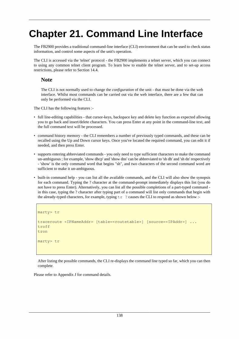
138
Chapter 21. Command Line InterfaceThe FB2900 provides a traditional command-line interface (CLI) environment that can be used to check statusinformation, and control some aspects of the unit's operation.
The CLI is accessed via the 'telnet' protocol - the FB2900 implements a telnet server, which you can connectto using any common telnet client program. To learn how to enable the telnet server, and to set-up accessrestrictions, please refer to Section 14.4.
Note
The CLI is not normally used to change the configuration of the unit - that must be done via the webinterface. Whilst most commands can be carried out via the web interface, there are a few that canonly be performed via the CLI.
The CLI has the following features :-
• full line-editing capabilities - that cursor-keys, backspace key and delete key function as expected allowingyou to go back and insert/delete characters. You can press Enter at any point in the command-line text, andthe full command text will be processed.
• command history memory - the CLI remembers a number of previously typed commands, and these can berecalled using the Up and Down cursor keys. Once you've located the required command, you can edit it ifneeded, and then press Enter.
• supports entering abbreviated commands - you only need to type sufficient characters to make the commandun-ambiguous ; for example, 'show dhcp' and 'show dns' can be abbreviated to 'sh dh' and 'sh dn' respectively- 'show' is the only command word that begins "sh", and two characters of the second command word aresufficient to make it un-ambiguous.
• built-in command help - you can list all the available commands, and the CLI will also show the synopsisfor each command. Typing the ? character at the command-prompt immediately displays this list (you donot have to press Enter). Alternatively, you can list all the possible completions of a part-typed command -in this case, typing the ? character after typing part of a command will list only commands that begin withthe already-typed characters, for example, typing tr ? causes the CLI to respond as shown below :-
marty> tr
traceroute <IPNameAddr> [table=<routetable>] [source=<IPAddr>] ...trofftron
marty> tr
After listing the possible commands, the CLI re-displays the command line typed so far, which you can thencomplete.
Please refer to Appendix J for command details.

139
Appendix A. Factory Reset ProcedureThe FireBrick has a simple factory reset process to erase the configuration allowing you to reconnect using thedefault IP addresses described in Chapter 2. This process can be very useful if you ever make an error in theconfiguration that stops you having access to the FireBrick for any reason, or any other situation where it isappropriate to start from scratch.
Only the first 4 ports are involved in the factory reset procedure, the 5th is not shown in these diagrams.
• Disconnect all network and power leads :-
• Connect lead between far left and far right ports (ports 1 and 4) :-
• Connect power and wait a few seconds for all port LEDs to be on steadily. Power LED blinks :-
• Disconnect loop, leave power connected. LEDs cycle and power LED blinks :-
Note
There is a timeout of 20 seconds in this process - if the loop is present for longer than 20 seconds,the power LED will stop flashing and the factory reset will be aborted

Factory Reset Procedure
140
• Connect network to left hand port. Power LED comes on solidly.
This process will start the FireBrick in a factory reset mode temporarily - the configuration stored in flashmemory has not yet been altered or deleted at this stage. If you disconnect the power then the config will revertto the previous state and no longer be reset, so it is important to connect your laptop, etc, to the FB2900 afterremoving the looped cable and not power cycle in-between.
If you do not save a new configuration at this stage, then the FB2900 will revert to the existing savedconfiguration when next powered up or restarted.
It is also possible to recover the configuration stored in flash memory, if you know an administrative usernameand password for it - this gives you an opportunity to correct a configuration, such as where you had made achange that prevented you from accessing the FB2900.
A.1. Other types of resetTo factory reset permanently follow the same process but with ports 1 and 2 looped - this will overwrite theconfiguration stored in flash memory, so use this reset method with caution.
To temporarily revert the configuration to the last-but-one saved config, follow the same process with ports 1and 3. Again, if the FB2900 if reset before saving a new config, it will revert to the last saved config again.

141
Appendix B. CIDR and CIDR NotationClassless Inter-Domain Routing (CIDR) is a strategy for IP address assignment originally specified in 1993that had the aims of "conserving the address space and limiting the growth rate of global routing state". Thecurrent specification for CIDR is in RFC4632 [http://tools.ietf.org/html/rfc4632].
The pre-CIDR eraCIDR replaced the original class-based organisation of the IP address space, which had become wasteful ofaddress space, and did not permit aggregation of routing information.
In the original scheme, only three sizes of network were possible :
• Class A : 128 possible networks each with 16,777,216 addresses
• Class B : 16384 possible networks each with 65,536 addresses
• Class C : 2097152 possible networks each with 256 addresses
Every network, including any of the large number of possible Class C networks, required an entry in globalrouting tables - those used by core Internet routers - since it was not possible to aggregate entries that had thesame routing information. The inability to aggregate routes meant global routing table size was growing fast,which meant performance issues at core routers.
The position and size of the network ID and host ID bitfields were implied by the bit pattern of some of themost significant address bits, which segmented the 32-bit IPv4 address space into three main blocks, one foreach class of network.
CIDRThe prefix notation introduced by CIDR was, in the simplest sense, "to make explicit which bits in a 32-bitIPv4 address are interpreted as the network number (or prefix) associated with a site and which are the usedto number individual end systems within the site". In this sense, the 'prefix' is the N most significant bits thatcomprise the network ID bitfield.
CIDR notation is written as :-
IPv4 : Traditional IPv4 'dotted-quad' number, followed by the "/" (slash) character, followed by a decimalprefix-length value between 0 and 32 (inclusive)
IPv6 : IPv6 address, followed by the "/" (slash) character, followed by a decimal prefix-length value between0 and 128 (inclusive)
Where formerly only three network sizes were available, CIDR prefixes may be defined to describe any powerof two-sized block of between one and 2^32 end system addresses, that begins at an address that is a multipleof the block size. This provides for far less wasteful allocation of IP address space. The size of the range isgiven by 2^M, where M = 32 - prefix_length
Routing destinationsAs well as being used to define a network (subnet), the CIDR notation is used to define the destination ina routing table entry, which may encompass multiple networks (with longer prefixes) that are reachable byusing the associated routing information. This, therefore, provides the ability to create aggregated routing tableentries.
For example, a routing table entry with a destination of 10.1.2.0/23 specifies the address range 10.1.2.0to 10.1.3.255 inclusive. As an example, it might be that in practice two /24 subnets are reachable via this

CIDR and CIDR Notation
142
routing table entry - 10.1.2.0/24 and 10.1.3.0/24 - routing table entries for these subnets would appear in adownstream router.
Note that in either a network/subnet or routing destination specification, the address will be the starting addressof the IP address range being expressed, such that there will be M least significant bits of the address set tozero, where M = 32 - prefix_length
Combined interface IP address and subnet definitionsAnother common use of the CIDR notation is to combine the definition of a network with the specification ofthe IP address of an end system on that network - this form is used in subnet definitions on the FB2900, andin many popular operating systems.
For example, the default IPv4 subnet on the LAN interface after factory reset is 10.0.0.1/24 - the addressof the FB2900 on this subnet is therefore 10.0.0.1, and the prefix length is 24 bits, leaving 8 bits for hostaddresses on the subnet. The subnet address range is therefore 10.0.0.0 to 10.0.0.255
A prefix-length of 32 is possible, and specifies a block size of just one address, equivalent to a plain IP addressspecification with no prefix notation. This is not the same as a combined subnet and interface-IP-addressdefinition, as it only specifies a single IP address.
General IP address range specificationsCIDR notation can also be used in the FB2900 to express general IP address ranges, such as in session-rules,trusted IP lists, access control lists etc. In these cases, the notation is the same as for routing destinations orsubnets, i.e. the address specified is the starting address of the range, and the prefix-length determines the sizeof the range.

143
Appendix C. MAC Addresses usageEthernet networks use 48 bit MAC addresses. These are globally unique and allocated by the equipmentmanufacturer from a pool of addresses that is defined by the first three octets (bytes), which identify theorganization, and are known as the Organizationally Unique Identifier (OUI). OUIs are issued by the IEEE -more information, and a searchable database of existing OUIs are available at http://standards.ieee.org/develop/regauth/oui/
MAC addresses are commonly written as six groups of two hexadecimal digits, separated by colons or hyphens.
FB2900s currently ship with an OUI value of 00:03:97.
In principle the FireBrick could have a single MAC address for all operations. However, practical experiencehas led to the use of multiple MAC addresses on the FireBrick. A unique block of addresses is assigned to eachFireBrick, with the size of the block dependent on the model.
Most of the time, FB2900 users do not need to know what MAC addresses the product uses. However, thereare occasions where this information is useful, such as when trying to identify what IP address a DHCP serverhas allocated to a specific FB2900. The subnet status page shows the MAC addresses currently in use on theEthernet interfaces.
C.1. Multiple MAC addresses?A MAC address does have to be unique on an Ethernet LAN segment, but typically a device will have oneMAC address, or one for each physical interface, preset by the network card in use. However, the FireBrickmakes use of multiple MAC addresses. There are two key reasons for this.
• The FireBrick can operate as a DHCP client device multiple times on the same LAN segment, obtainingseveral separate IP addresses. This is useful on some cable modem type installations where multiple IPsare only available if the FireBrick appears to be multiple devices at once. Whilst DHCP theoretically doesnot need separate MAC addresses, experience suggests this is by far the most practical approach. If youhave more than one DHCP client subnets in your configuration they will automatically get separate MACaddresses.
• In theory the scope of a MAC address is a single LAN segment. The fact that they are globally uniqueis simply to avoid any clashes on a LAN segment. However, once again, practical experience shows thatsome network devices and some network switches do not handle the concept of the same MAC addressappearing on different ports or VLANs within the network. This can lead to broken networks or traffic leaksbetween VLANs, neither of which is good. For this reason the FireBrick uses distinct MAC addresses oneach interface.
C.1. Using the same MAC addressThere are cases where it is sensible or requires to use the same MAC address for more than one thing. For astart, the FireBrick does not have unlimited MAC addresses, but there are other reasons, for example:-
• Distinct subnets on the same LAN segment do not cause any switch/MAC issues as the FireBrick appearsto simply be one device on the LAN segment with multiple IPs. This is quite a normal configuration fornetwork devices. In these cases the FireBrick can use the same MAC address for multiple IPs on the sameLAN segment.
• There can be MAC restrictions on some devices - this is mainly at the ISP level where peering points andnetwork connections may be set up with limited MAC addresses. In such cases any packet with a differentMAC address seen on a port can cause the port to shut down, or the additional MAC addresses to be blocked.For this reason there are cases where multiple subnets need to be restricted to exactly one MAC address.

MAC Addresses usage
144
TipThe interface settings in the configuration have a restrict-mac setting which, when set totrue causes the same MAC to be used for all subnets and operations on that specific interface(port group / VLAN combination).
C.2. Changing MAC addressThere is no reason for any network device to maintain the same MAC address for ever. It is normal for theMAC address to change if the network card is changed on a PC, for example.
However, it is inconvenient if MAC addresses change simply because a device is power cycled or a newconfiguration is loaded. This can cause delays accessing the device if other devices have the MAC cached. Itis also a serious problem for ISP links as above where ports are locked to only accept one MAC.
The way the FireBrick manages MAC addresses is designed to be a bit sticky so that a config change will notusually cause a MAC address assigned to a subnet or interface to change.
C.2. How the FireBrick allocates MACaddresses
To meet these requirements the FireBrick allocates MAC addresses so specific aspects of the configurationwhen it is loaded, and stores this separately in persistent data. If the config is then changed, such as changingthe order of interface definitions, then the allocated MAC stays with the config object based on some key aspect(such as port group and VLAN tag for interfaces, or IP for subnets).
C.2.1. InterfaceEach interface object is allocated a MAC, keyed by the port group and VLAN tag of the interface. This is usedfor dynamic IPv6 allocation on the interface using router announcements (RA) as well as OSPF and any otherinterface specific uses that are not relates to a subnet.
C.2.2. SubnetEach subnet object is allocated a MAC, which is used for all of the IPs listed in that subnet object. This allowsmany IPs to have the same MAC by listing them in the same subnet object. The MAC allocation is keyed onthe port group and VLAN tag and the first listed IP address in the subnet. If a later subnet has the same first IPlisted then this is allocated a separate MAC (i.e. the key for the MAC is also based on which instance of thisspecific first IP it is, 1st, 2nd, 3rd, within the interface).
DCHP client subnets work in much the same way - they are based on the port group and VLAN tag and whichinstance of DHCP client they are (1st, 2nd, 3rd, etc) within the interface. The special case for DHCP clients isthat the first of these within an interface is given the same MAC as the interface itself.
C.2.3. PPPoEEach PPPoE object is given a MAC. This is keyed on the port group and VLAN and works in the same wayas if it was a DHCP client subnet in a corresponding interface. i.e. where there is an interface with same portgroup and VLAN the PPPoE object gets the interface MAC.
C.2.4. Base MACThe factory default config has interfaces listed left to right, and a DHCP client in the first interface. This meansthe base MAC address of the FireBrick is allocated to the left hand interface and DHCP client on that interface.This is the same MAC address used by the boot loader which transmits on the left most port on power up.

MAC Addresses usage
145
C.2.5. Running out of MACsThe allocations are recorded in persistent data, so if an object is removed from the config and later put backit should get the same MAC address. If however there are not enough MAC addresses when loading a config,then previous assignments are re-used. If there are too many interface, subnet and ppp objects within the configto allocate MAC addresses (even reusing old allocations) then an error is given and the config cannot be loaded.
TipUsing restrict-mac on an interfaces restricts that interface (port group/VLAN) to only use oneMAC and not one per subnet.
C.3. MAC address on labelThe label attached to the bottom of the FB2900 shows what MAC address range that unit uses, using a compactnotation, as highlighted in Figure C.1 :-
Figure C.1. Product label showing MAC address range
The X in the MAC address shows that that point could be any value 0 to F.
C.4. Using with a DHCP serverIf your DHCP server shows the name of the client (FB2900) that issued the DHCP request, then you willsee a value that depends on whether the system name is set on the FB2900, as shown in Table C.1. Refer toSection 4.2.1 for details on setting the system name.
Table C.1. DHCP client names used
System name Client name used
not set (e.g. factory reset configuration) FB2900
set Main application software running
If the FB2900's system name is set, and your DHCP server shows client names, then this is likely to be thepreferred way to locate the relevant DHCP allocation in a list, rather than trying to locate it by MAC address.If the FB2900 is in a factory-reset state, then the system name will not be set, and you will have to locate itby MAC address.

146
Appendix D. Scripted accessThe web interface for the FireBrick is mainly intended to be used by use of a web browser, however, there area number of cases where the use from scripts or tools can be useful. This appendix covers some of the ways theFireBrick web interface can be used. Some of these are already mentioned in other sections, such as customisedCQM archiving URLs, and so not repeated here. We also do not cover loading and saving a new config.
D.1. ToolsThere are a great many tools for accessing web pages, in a variety of languages. Please feel free to use whichevertools you are happy with.
In this section we suggest the use of the linux command line tool curl, and all of the examples are based on this.
D.2. Access controlYou will need to consider access control carefully if using scripts to access the FireBrick. In particular youneed to ensure that someone that has access to the scripts, or simply a copy of the script, could gain unfetteredaccess to your FireBrick(s).
D.2.1. Username and passwordYou will probably want to create a separate user for the script access, with a separate password. You can thenmake use of this with a command like curl using the --user= argument in the script.
NoteWe do not recommend simply hard coding the password, and it may be better to have passwords stotedin a database of some sort. This will depend on your own security procedures.
D.2.2. OTPYou could, if you have the tools to manage OTP codes, make use of an OTP seed for your script user.Remember that the authentication system allows the OTP code to be pre-pended to the password, e.g. --user=name:123456password. This is recommended if using http access which can be snooped upon.
D.2.3. Allow listWe strongly recommend you have additional allow list access controls on your script user to lock down tomachines which will be accessing the FireBrick. You may even want different users for different scripts,machines running scripts, and FireBricks depending on your own security policies.
D.2.4. Allowed accessIt is likely that scripts, as described in this appendix, will not need to access or change the configuration onyour FireBricks, and so you can lock down access for the user to restrict access to the config.
NoteIf you do have scripts that update configuration, you may want this to user a different user for securityreasons.
D.3. XML data for common functionsWhen using the web interface you will encounter a number of cases where there is an XML link shown. Forexample, in Status/Subnets. This has an XML link to /status/subnets/xml.

Scripted access
147
This is an example of one of the many places that an XML version of some user data can be accessed. We havenot listed all of these in the manual as you can see them in the web pages that include the XML link.
D.4. XML data from diagnostics and testsMany of the diagnostic tools also include an XML link or check box, for example the Diagnostics/Ping.
D.4.1. Cross site scripting securityWhen using the web page, the page expects that you will post back a special code that was included as a hiddenfield. This is to prevent the use of cross site scripting where a form on a separate web page will attempt to postto your FireBrick with arguments that do something on your FireBrick, hoping you happen to be logged in tothe FireBrick still on your browser.
However, where an Authentication header is used, such as the --user= option on curl this requirement isdropped, and so you can make scripts work with a single curl command with authentication and arguments.
D.4.2. Arguments to scriptsMost tools (e.g. ping) require some arguments. The simplest way to identify these is to see what is in the formon the web site. In some cases the field name sare actually taken from the command line, which means that insome cases the field name is just a number. For example, ping needs 1 as a field with the IP address to ping,and count as the ping count. Typically all arguments are in fact optional, so do not need to be included.
The arguments need to be supplied as if sent from a form. In most cases these can be passed as a query stringstyle, or as posted form data.
For example:-
curl http://my.firebrick.uk/diag/ping/p --user adrian:237426 --data 1=8.8.8.8 --data xml
The result being:-
<?xml version="1.0" encoding="UTF-8"?><status xmlns="http://firebrick.ltd.uk/xml/statusv1" xmlns:xsi="http://www.w3.org/2001/XMLSchema-instance" xsi:schemaLocation="http://firebrick.ltd.uk/xml/statusv1 http://firebrick.ltd.uk/xml/statusv1.xsd" firmware-version="TEST Yorick+ (V1.46.189A2 2018-03-09T15:56:05)" generated="2018-03-10T13:50:10Z"><note>Pinging 8.8.8.8 from 90.155.42.98</note><ping><ping number='1' time='3.848' ip='8.8.8.8' note='Reply' name='google-public-dns-a.google.com'/><ping number='2' time='3.985' ip='8.8.8.8' note='Reply' name='google-public-dns-a.google.com'/><ping number='3' time='3.724' ip='8.8.8.8' note='Reply' name='google-public-dns-a.google.com'/><ping number='4' time='3.848' ip='8.8.8.8' note='Reply' name='google-public-dns-a.google.com'/><ping number='5' time='3.911' ip='8.8.8.8' note='Reply' name='google-public-dns-a.google.com'/><ping number='6' time='4.298' ip='8.8.8.8' note='Reply' name='google-public-dns-a.google.com'/><ping number='7' time='3.839' ip='8.8.8.8' note='Reply' name='google-public-dns-a.google.com'/><ping number='8' time='3.748' ip='8.8.8.8' note='Reply' name='google-public-dns-a.google.com'/><ping number='9' time='3.796' ip='8.8.8.8' note='Reply' name='google-public-dns-a.google.com'/><ping number='10' time='3.722' ip='8.8.8.8' note='Reply' name='google-public-dns-a.google.com'/><summary sent='10' received='10' loss='0.00' minimum='3.722' average='3.871' maximum='4.298'/></ping>

Scripted access
148
</status>
NoteThe form will typically include an XML check box, hence the use of --data xml in the exampleso as to include this as a field that is sent in teh query string.
D.5. Special URLsA number of special URLs exist purely for script use, as follows.
Table D.1. Special URLs
URL Type Function
reboot HTML Simple reboot
reboot-when-free HTML Reboot when free
reboot-cancel HTML Cancel the reboot when free ifpossible
reboot-hard HTML Forced hard reboot now
capability HTML Return XML capability
schema HTML Return XML that is the internalformat config edit schema
timestamp Text Timestamp of config
ip Text Your IP address as seen by theFireBrick
version Text Current software version
et Text Current software version, or anHTTP level error with textexplaining why, such as Upgraderequired.
D.6. Web socketsThere are some web socket feeds available, generally these are used internally for config edit, status page, andlogging, etc. However, we may add additional specific URLs for script use in due course. The general principleis that the websocket feed provides a stream of JSON objects in real time.

149
Appendix E. VLANs : A primerAn Ethernet (Layer 2) broadcast domain consists of a group of Ethernet devices that are interconnected,typically via switches, such that an Ethernet broadcast packet (which specifies a reserved broadcast address asthe destination Ethernet address of the packet) sent by one of the devices is always received by all the otherdevices in the group. A broadcast domain defines the boundaries of a single 'Local Area Network'.
When Virtual LANs (VLANs) are not in use, a broadcast domain consist of devices (such as PCs and routers),physical cables, switches (or hubs) and possibly bridges. In this case, creating a distinct Layer 2 broadcastdomain requires a distinct set of switch/hub/bridge hardware, not physically interconnected with switch/hub/bridge hardware in any other domain.
A network using Virtual LANs is capable of implementing multiple distinct Layer 2 broadcast domains withshared physical switch hardware. The switch(es) used must support VLANs, and this is now common in cost-effective commodity Ethernet switches. Inter-working of VLAN switch hardware requires that all hardwaresupport the same VLAN standard, the dominant standard being IEEE 802.1Q.
Such switches can seggregate physical switch ports into user-defined groups - with one VLAN associated witheach group. Switching of traffic only occurs between the physical ports in a group, thus isolating each groupfrom the others. Where more than one switch is used, with an 'uplink' connection between switches, VLANtagging is used to multiplex packets from different VLANs across these single physical connections.
A IEEE 802.1Q VLAN tag is a small header prefixed to the normal Ethernet packet payload, includes a 12-bitnumber (range 1-4095) that identifies the tagged packet as belonging to a specific VLAN.
When a tagged packet arrives at another switch, the tag specifies which VLAN it is in, and switching to theappropriate physical port(s) occurs.
In addition to VLAN support in switches, some end devices incorporate VLAN support, allowing them to sendand receive tagged packets from VLAN switch infrastructure, and use the VLAN ID to map packets to multiplelogical interfaces, whilst only using a single physical interface. Such VLAN support is typically present indevices that are able to be multi-homed (have more than one IP interface), such as routers and firewalls, andgeneral purpose network-capable operating systems such as Linux.
The FB2900 supports IEEE 802.1Q VLANs, and will accept (and send) packets with 802.1Q VLAN tags. It cantherefore work with any Ethernet switch (or other) equipment that also supports 802.1Q VLANs, and thereforeallows multiple logical interfaces to be implemented on a single physical port.
VLAN tagged switching is now also used in Wide-Area Layer 2 Ethernet networks, where a Layer 2 'circuit'is provided by a carrier over shared physical infrastructure. The conventional concept of a LAN occupying asmall geographic area is thus no longer necessarily true.

150
Appendix F. Supported L2TPAttribute/Value Pairs
This appendix details the L2TP protocol messages supported, and the attribute/value pairs (AVPs) which aresent and expected for each message.
F.1. Start-Control-Connection-Request
Table F.1. SCCRQ
AVP No. Incoming Outgoing
Message Type 0 Value 1 Value 1
Protocol Version 2 Mandatory, value 1 expected Value 1
Framing Capabilities 3 Ignored Value 3
Bearer Capabilities 4 Ignored Not sent
Tie Breaker 5 Ignored as FireBrick only acceptsconnections for inbound calls
Not sent
Firmware Revision 6 Ignored FireBrick s/w version string
Host Name 7 Used to select which incoming L2TPconfiguration applies.
As per config/RADIUS request
Vendor Name 8 Ignored FireBrick Ltd
Assigned Tunnel ID 9 Mandatory Mandatory, our tunnel ID
Receive Window Size 10 Accepted, assumed 4 if not present orless than 4 is specified
Value 4
Challenge 11 Accepted if a configured secret isdefined, a response is sent in theSCCRP
Not sent at present
F.2. Start-Control-Connection-Reply
Table F.2. SCCRP
AVP No. Incoming Outgoing
Message Type 0 Value 2 Value 2
Protocol Version 2 Value 1 expected Value 1
Framing Capabilities 3 Ignored Value 3
Bearer Capabilities 4 Ignored Not sent
Firmware Revision 6 Ignored FireBrick s/w ID number
Host Name 7 Logged as hostname for tunnel Configured hostname, if defined
Vendor Name 8 Ignored FireBrick Ltd
Assigned Tunnel ID 9 Expected as far end ID Mandatory, our tunnel ID
Receive Window Size 10 Accepted, assimed 4 if not present orless than 4
Not sent, assume 4

Supported L2TPAttribute/Value Pairs
151
Challenge 11 Accepted if a configured secret isdefined, a response is sent in theSCCCN
Not sent at present
Challenge Response 13 Not expected at present Sent if SCCRQ contained a challengeand we have a secret defined
F.3. Start-Control-Connection-ConnectedTable F.3. SCCCN
AVP No. Incoming Outgoing
Message Type 0 Value 3 Value 3
Challenge Response 13 Not expected Sent if was challenged
F.4. Stop-Control-Connection-NotificationTable F.4. StopCCN
AVP No. Incoming Outgoing
Message Type 0 Value 4 Value 4
Result Code 1 Ignored (logged) Sent as appropriate for tunnel close
Assigned Tunnel ID 9 Expected, see note Sent if a tunnel has been allocated
Note that a StopCCN may not have a zero tunnel ID in the header. If this is the case the source IP, port andassigned tunnel are used to identify the tunnel.
If an unknown tunnel ID is received on any any incoming packet a StopCCN is generated (once per 10 seconds)with header tunnel ID 0 and specified assigned tunnel ID.
F.5. HelloTable F.5. HELLO
AVP No. Incoming Outgoing
Message Type 0 Value 6 Value 6
Always responded to. Sent periodically if no other messages sent.
F.6. Incoming-Call-RequestTable F.6. ICRQ
AVP No. Incoming Outgoing
Message Type 0 Value 10 Value 10
Assigned Session ID 14 Mandatory Mandatory, our session ID
Call Serial Number 15 Accepted and passed on if relaying Passed on incoming value
Bearer Type 18 Ignored Not sent
Called Number 21 Accepted, used in RADIUS and passedon if relaying
Passed on incoming value
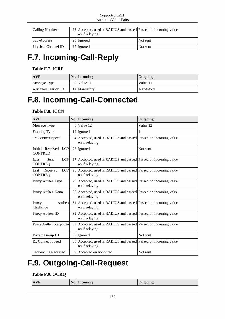
Supported L2TPAttribute/Value Pairs
152
Calling Number 22 Accepted, used in RADIUS and passedon if relaying
Passed on incoming value
Sub-Address 23 Ignored Not sent
Physical Channel ID 25 Ignored Not sent
F.7. Incoming-Call-ReplyTable F.7. ICRP
AVP No. Incoming Outgoing
Message Type 0 Value 11 Value 11
Assigned Session ID 14 Mandatory Mandatory
F.8. Incoming-Call-ConnectedTable F.8. ICCN
AVP No. Incoming Outgoing
Message Type 0 Value 12 Value 12
Framing Type 19 Ignored 1
Tx Connect Speed 24 Accepted, used in RADIUS and passedon if relaying
Passed on incoming value
Initial Received LCPCONFREQ
26 Ignored Not sent
Last Sent LCPCONFREQ
27 Accepted, used in RADIUS and passedon if relaying
Passed on incoming value
Last Received LCPCONFREQ
28 Accepted, used in RADIUS and passedon if relaying
Passed on incoming value
Proxy Authen Type 29 Accepted, used in RADIUS and passedon if relaying
Passed on incoming value
Proxy Authen Name 30 Accepted, used in RADIUS and passedon if relaying
Passed on incoming value
Proxy AuthenChallenge
31 Accepted, used in RADIUS and passedon if relaying
Passed on incoming value
Proxy Authen ID 32 Accepted, used in RADIUS and passedon if relaying
Passed on incoming value
Proxy Authen Response 33 Accepted, used in RADIUS and passedon if relaying
Passed on incoming value
Private Group ID 37 Ignored Not sent
Rx Connect Speed 38 Accepted, used in RADIUS and passedon if relaying
Passed on incoming value
Sequencing Required 39 Accepted on honoured Not sent
F.9. Outgoing-Call-RequestTable F.9. OCRQ
AVP No. Incoming Outgoing

Supported L2TPAttribute/Value Pairs
153
Message Type 0 Value 7 Value 7
Not supported, ignored.
F.10. Outgoing-Call-ReplyTable F.10. OCRP
AVP No. Incoming Outgoing
Message Type 0 Value 8 Value 8
Not supported, ignored.
F.11. Outgoing-Call-ConnectedTable F.11. OCCN
AVP No. Incoming Outgoing
Message Type 0 Value 9 Value 9
Not supported, ignored.
F.12. Call-Disconnect-NotifyTable F.12. CDN
AVP No. Incoming Outgoing
Message Type 0 Value 14 Value 14
Result Code 1 Ignored (logged) Sent as appropriate for tunnel close
Q.931 Cause Code 12 Ignored Not sent
Assigned Session ID 14 Expected, see note Sent if assigned
Note that a CDN may have a zero session ID in the header. If this is the case the tunnel ID and assigned sessionID are used to identify the session.
If an unknown session ID on a known tunnel ID is received on any any incoming packet a CDN is generatedwith header session ID 0 and specified assigned session ID.
F.13. WAN-Error-NotifyTable F.13. WEN
AVP No. Incoming Outgoing
Message Type 0 Value 15 Value 15
Not supported, ignored.
F.14. Set-Link-InfoTable F.14. SLI
AVP No. Incoming Outgoing

Supported L2TPAttribute/Value Pairs
154
Message Type 0 Value 16 Value 16
Not supported, ignored.
F.15. Notes
F.15.1. BT specific notesThe L2TP and PPP specifications are clear that the HDLC framing bytes are not sent or received within theL2TP packet. However, BT send type bytes (FF03) on the start of all PPP frames. This is silently discarded.Also, BT will not process packets if these type bytes are not included in outgoing packets. Sending the HDLCframing can be controlled in the config and on a per session basis using a Filter-Id in RADIUS authenticationresponse.
BT sometimes negotiate incorrect MRUs on behalf of the LNS. Where the L2TP proxy details indicate andincorrect MRU has been negotiated then LCP negotiation is restarted and the correct MRU negotiates. Thishelps avoid various issues with fragmentation on some services on the internet when the broadband fullysupports 1500 byte MTU. This is also relevant where the FB6000 is deliberately configured to use a smallerMRU for example when the L2TP connection is remote via a 1500 MTU link.
There are options using Filter-Id from RADIUS to force LCP restart. However this does confuse some pppimplementations as it is after authentication is complete. This can be useful where BT have provided anincorrect MRU for the end user (another bug). There is also an option to forward 1500 byte packets rather thanfragmenting them. When enabled ICMP is still generated for DF and IPv6.
F.15.2. IP over LCPIP over LCP is a non standard coding of PPP packets for IPv4 and IPv6. The coding uses the LCP code (C021)instead of the IPv4 (0021) or IPv6 (0057) code. The first byte which would normally be the LCP type is 0x4X(IPv4) or 0x6X (IPv6). The FireBrick assumes any such LCP codes are IPv4/IPv6 when received, and using aRADIUS response can send IP packets using LCP. This is specifically to bypass any carrier IP specific shapingor DPI.

155
Appendix G. Supported RADIUSAttribute/Value Pairs for L2TPoperation
RADIUS is used for authentication and accounting of L2TP connections. If no authentication servers areconfigured then authentication is not performed. If no accounting servers are configured then no accountingis generated. Multiple servers can be configured and they are processed in order. Each can have multiple IPaddresses. The IP addresses are tried based on the previous performance (response time, etc). If a server doesnot respond a number of times as configured then it is blacklisted for a configurable period.
It is possible to configure local configurations which are checked before any RADIUS authentication.
It is possible to configure L2TP so that RADIUS accounting must respond, and if not then the sessions aredisconnected.
G.1. Authentication requestTable G.1. Access-request
AVP No. Usage
Message-Authenticator
80 Message signature as per RFC2869
User-Name 1 Username from authentication (PAP/CHAP) or proxy authentication receivedon L2TP
Called-Station-Id 30 Called number as received on L2TP
Calling-Station-Id 31 Calling number as received on L2TP
Acct-Session-Id 44 Unique ID for session as used on all following accounting records
NAS-Identifier 32 Configured hostname of FireBrick
NAS-IP-Address 4 NAS IPv4 address if using IPv4
NAS-IPv6-Address 95 NAS IPv6 address if using IPv6
NAS-Port 5 L2TP session ID
NAS-Port-Id 87 For PPPoE "port{:vlan}/MAC"
Service-Type 6 Framed
Framed-Protocol 7 PPP
CHAP-Password 3 CHAP ID and response
CHAP-Challenge 60 CHAP challenge (only present if not the same as RADIUS authenticator)
Framed-MTU 12 MTU requested by PPP, if one was requested (even if 1500)
Connect-Info 77 Text Tx speed/Rx speed from L2TP connection if known
Tunnel-Client-Endpoint
66 Indicates the L2TP tunnel configured name attribute, allowing connections viadifferent L2TP incoming configurations to be identified
Proxy-State 33 Added to session steering RADIUS requests (i.e. previous RADIUS returnedtype S tunnel)
Note that the NAS-IP-Address is normally the local end of the L2TP connection for the incoming connection.However, there is a configuration option to pass the remote end of the L2TP as the NAS-IP-Address as this isoften more useful. If the remote Ip is used the NAS-Port is set to the far end L2TP session ID rather than the

Supported RADIUS Attribute/Value Pairs for L2TP operation
156
local end session ID. The NAS-Identified remains the name of the FB6000. This option is separately availablefor accounting messages.
Note that the Calling-Station-Id is included even if not present in L2TP connection if a cache platform RADIUSrequest matched the L2TP connection and had a Calling-Station-Id.
G.2. Authentication response
G.2.1. Accepted authentication
Table G.2. Access-Accept
AVP No. Usage
Reply-Message 18 Reply message sent on PPP authentication response
MS-Primary-DNS-Server
311/28 Primary DNS address used in PPP IPCP (Vendor 311 specific)
MS-Secondary-DNS-Server
311/29 Secondary DNS address used in PPP IPCP (Vendor 311 specific)
Framed-Interface-ID 96 Peer IPv6 Interface ID expected in PPP IPV6CP
Framed-IP-Address 8 Peer IPv4 address expected in PPP IPCP (does not support 255.255.255.255or 255.255.255.254 yet). Maximum localpref used.
NAS-IP-Address 4 Our end IPv4 address to in IPCP negotiation. Does not add loopback route.This is non standard.
Framed-Route 22 May appear more than once. Text format is IPv4-Address/Bits 0.0.0.0 metric.The target IP is ignored but must be valid IPv4 syntax. The metric is used aslocalpref in routing.
Delegated-IPv6-Prefix
123 IPv6 prefix to be routed to line. Maximum localpref used.
Framed-IPv6-Prefix 97 IPv6 prefix to be routed to line. Maximum localpref used.
Framed-IPv6-Route 99 May appear more than once. Text format is IPv6-Address/Bits :: metric. Thetarget IP is ignored but must be valid IPv6 syntax. The metric is used aslocalpref in routing. Alternative format IPv6/Bits IPv4-Address metric definesthat prefix is to be protocol 41 IPv4 tunneled to specified target via this link.
Framed-IPv6-Address 168 Adds a /128 IPv6 route.
User-Name 1 Username may be specified - this replaces the username already present andis then used on accounting start and relay L2TP.
CHAP-Challenge 60 Overwrite relay details: If no length then forces PAP, else forces CHAP andsets challenge. Send before CHAP-Password or User-Password in packet.
CHAP-Password 3 Overwrite relay details: This replaces the CHAP ID and CHAP response
User-Password 2 Overwrite relay details: (not, plain text, not encoded). If CHAP, sets a responsebased on this, else forces PAP using this password.
Called-Station-Id 30 Called number may be specified - this replaces the number already present
Calling-Station-Id 31 Calling number may be specified - this replaces the number already present
Chargeable-User-Identity
89 This is used as the preferred CQM graph name.
Class 25 Secondary CQM graph name to group sessions allowing group logging orshaping.
Session-Timeout 27 Absolute limit on session, in seconds

Supported RADIUS Attribute/Value Pairs for L2TP operation
157
Filter-Id 11 See filter ID section
Framed-MTU 12 Set MTU for session
Connect-Info 77 Text tx/rx speed limit to apply to session (see below)
Tunnel-Type 64 If specified must be 3 (L2TP), L2TP is assumed. Also allows special 'R' and'S' types, see below.
Tunnel-Medium-Type 65 If specified must be 1 (IPv4) or 2 (IPv6), syntax of endpoint is used if this isnot specified
Tunnel-Server-Endpoint
67 Text IPv4 or IPv6 address of endpoint (FQDN is not accepted)
Tunnel-Client-Auth-ID
90 Hostname to quote on outgoing tunnel, if omitted then configured FireBrickhostname is used
Tunnel-Password 69 Shared secret to use on outgoing tunnel (encrypted), if omitted then assumedno secret
Tunnel-Assignment-ID
81 Name of outgoing tunnel shaper/graph. Also groups sessions together in atunnel as per RFC. Only use valid text graph names.
Tunnel-Preference 83 Specifies preference order when multiple tagged endpoints sent
Note that whilst a RADIUS response is normally relatively small in can get larger when multiple tunnelendpoints are included. Fragmented responses are handled but there is an internal limit to the size of responsethat can be processed - as such we recommend keeping the response to a single un-fragmented packet of up to1500 bytes. You can use tag 0 for common settings such as Tunnel-Client-Auth-ID or Tunnel-Password whenusing multiple endpoints in order to reduce the size of the response.
The Tunnel-Type can be special, non-RFC values: 'R' (0x52)or 'S' (0x53) to indicate that the Tunnel-Server-EndPoint is the name or IP of a further RADIUS server to be interrorgated. For 'R' this may respond with anyvalid authentication response. For 'S' the response will have all IP assignments filtered, and also not allow aTunnel-Type 'S' response. Only one, tag 0 (untagged), RADIUS referral response will be accepted. The endpointspecified is server name or IP, and can have a number of numeric values appended (#port, >mintimeout,<maxtimeout, *scale, ?maxqueue).
The Connect-Info response can be a simple number (bits/second) tx rate, or a number followed by a % wherethis sets a speed based on a percentage of connection line speed. This can be followed by a slash (/) and thesame for rx rate if required (default is rx is not limited). It is also possible to set long term shapers where aChargeable-User-Identity is also included, this involves a number of additional parameters in the string prefixedwith characters: > min, < max, _ minburst, and \ step.
Some of the response fields are somewhat unconventional, such as User-Name and User-Password, allowingexisting entries to be overwritten. These impact any details passed in a RADIUS accounting start and alsoimpact relayed L2TP connections. Note that these can also impact if a secondary RADIUS request is done (e.g.if far end sends a new CHAP response, for example).
G.2.1.1. Prefix Delegation
The RADIUS authentication response can include Delegated-IPv6-Prefix, Framed-IPv6-Prefix, and Framed-IPv6-Route in order to route native IPv6 prefixes to the line. If there are any native IPv6 routes, or the Framed-IPv6-Interface attribute was specified, then IPV6CP negotiation is started. Framed-IPv6-Route can also be usedto added IPv4 tunneled routes to the line. The FE80::/10 link local address negotiated with IPV6CP is not addedto the routing for the line.
The client can send a Router solicitation to which the FireBrick will reply advising to use DHCPv6 foraddressing. Once a router solicitation is sent, periodic Router Advertisements will then be sent on the connectionby the Firebrick.
The client can use DHCPv6 to request an IA_NA (/128 link address), IA_TA (/128 temp link address), IA_PD(Prefic delegation) and DNS servers. Prefixes are delegated based on the order in the DHCPv6 request and the

Supported RADIUS Attribute/Value Pairs for L2TP operation
158
order of Delegated-IPv6-Prefix, Framed-IPv6-Prefix, and then Framed-IPv6-Route, with multiple such entriesin the order that they appeared in the RADIUS response. Such prefixes are not split up if a smaller prefix isrequested, but the first part of a prefix is delegated.
As you can see, it is possible to send back CHAP-Challenge and CHAP-Password or User-Password to overridethose received by proxy or negotiation. This is mainly used when relaying the L2TP onwards and changes theproxy authentication field sent. This also overrides the Last LCP Tx proxy setting to show PAP/CHAP or noauthentication as having been negotiated.
G.2.2. Rejected authentication
Table G.3. Access-Reject
AVP No. Usage
Reply-Message 18 Reply message sent on PPP authentication response
Note that an authentication reject will normally cause the reply message to be sent as an authentication rejectmessage. The reply "Try another" causes the L2TP session to be closed with result/error 2/7 (Try another)without sending an authentication reply on PPP.
G.3. Accounting StartTable G.4. Accounting-Start
AVP No. Usage
Acct-Status-Type 40 1 Start
User-Name 1 Username from authentication (PAP/CHAP) or proxy authentication receivedon L2TP or received in authentication response
Class 25 From authentication response if present
Chargeable-User-Identity
89 Graph name that applies, sanitised to comply with CQM graph name rules..
Called-Station-Id 30 Called number as received on L2TP
Calling-Station-Id 31 Calling number as received on L2TP
Service-Type 6 Framed
Framed-Protocol 7 PPP
Framed-MTU 12 Final MTU being used for session
Filter-Id 11 Filters in use
Session-Timeout 27 Absolute limit on session, in seconds, if specified in authentication reply
Framed-Interface-ID 96 Peer IPv6 Interface ID from PPP IPV6CP
Framed-IP-Address 8 Peer IPv4 address negotiated in PPP (normally from authentication response)
Connect-Info 77 Text Tx speed/Rx speed in use
Acct-Delay-Time 41 Seconds since session started
Acct-Event-Timestamp
55 Session start time (unix timestamp)
Acct-Session-Id 44 Unique ID for session
NAS-Identifier 32 Configured hostname of FireBrick
NAS-IP-Address 4 NAS IPv4 address if using IPv4
NAS-IPv6-Address 95 NAS IPv6 address if using IPv6

Supported RADIUS Attribute/Value Pairs for L2TP operation
159
NAS-Port 5 L2TP session ID
Tunnel-Type 64 Present for relayed L2TP sessions, L2TP
Tunnel-Medium-Type 65 Present for relayed L2TP, 1 (IPv4) or 2 (IPv6)
Tunnel-Client-Endpoint
66 Present for relayed L2TP, text IPv4 or IPv6 address of our address on theoutbound tunnel
Tunnel-Server-Endpoint
67 Present for relayed L2TP, text IPv4 or IPv6 address of the far end address ofthe outbound tunnel
Tunnel-Assignment-ID
82 Present for relayed L2TP, text local L2TP tunnel ID
Tunnel-Client-Auth-ID
90 Present for relayed L2TP, local end hostname quoted by outgoing tunnel
Tunnel-Server-Auth-ID
91 Present for relayed L2TP, far end hostname quoted by outgoing tunnel
Note that most parameters are not included in interim and stop accounting records. The acct-session-id shouldbe used by accounting servers to correlate interim and stop records with the start record. The graph name couldbe used, but is only available where there is a graph. If too many different graphs then that is not present. Someexceptions apply as they can be changed by a change of authorisation RADIUS request, such as Connect-Info.
G.4. Accounting InterimTable G.5. Accounting-Interim
AVP No. Usage
Acct-Status-Type 40 3 Interim-Update
Acct-Delay-Time 41 Seconds since accounting data collected
Acct-Event-Timestamp
55 Data collected time (unix timestamp)
Acct-Session-Id 44 Unique ID for session
Chargeable-User-Identity
89 Graph name that applies, sanitised to comply with CQM graph name rules..
Connect-Info 77 Text Tx speed/Rx speed in use
NAS-Identifier 32 Configured hostname of FireBrick
NAS-IP-Address 4 NAS IPv4 address if using IPv4
NAS-IPv6-Address 95 NAS IPv6 address if using IPv6
NAS-Port 5 L2TP session ID
Acct-Input-Octets 42 Rx byte count
Acct-Input-Gigawords
52 Rx byte count (high 4 bytes)
Acct-Output-Octets 43 Tx byte count
Acct-Output-Gigawords
53 Tx byte count (high 4 bytes)
Acct-Input-Packets 47 Rx packet count
Acct-Output-Packets 48 Tx packet count
Tunnel-Type 64 Present for relayed L2TP sessions, L2TP
Tunnel-Medium-Type 65 Present for relayed L2TP, 1 (IPv4) or 2 (IPv6)

Supported RADIUS Attribute/Value Pairs for L2TP operation
160
Tunnel-Client-Endpoint
66 Present for relayed L2TP, text IPv4 or IPv6 address of our address on theoutbound tunnel
Tunnel-Server-Endpoint
67 Present for relayed L2TP, text IPv4 or IPv6 address of the far end address ofthe outbound tunnel
Tunnel-Assignment-ID
82 Present for relayed L2TP, text local L2TP tunnel ID
Tunnel-Client-Auth-ID
90 Present for relayed L2TP, local end hostname quoted by outgoing tunnel
Tunnel-Server-Auth-ID
91 Present for relayed L2TP, far end hostname quoted by outgoing tunnel
G.5. Accounting StopAs accounting interim update plus
Table G.6. Accounting-Stop
AVP No. Usage
Acct-Terminate-Cause
49 Cause code as appropriate
Cause codes of note are 2(Lost-Carrier) which is sent if LCP echos do not reply for several seconds, and 14(Port-Suspended) which is sent if the dos-limit is exceeded on a session. For DOS handling is is recommended thatsubsequent authentication requests are rejected for several minutes or a fake accept is and session-timeout isused as DOS attacks usually continue until the customer is off-line.
G.6. DisconnectA disconnect message is accepted as per RFC5176, if the session can be disconnected, and ACK is sent, elsea NAK
Table G.7. Disconnect
AVP No. Usage
Acct-Session-Id 44 Unique ID for session
Chargeable-User-Identity
89 This is used as CQM graph name.
Acct-Terminate-Cause
49 Cause code as appropriate to be used in accounting stop message
The session is identified by Acct-Session-Id if present, else by Chargeable-User-Identity. No otheridentification parameters are supported. If sent then they are ignored.
G.7. Change of AuthorisationA change of authorisation message is accepted as per RFC5176
Table G.8. Change-of-Authorisation
AVP No. Usage
Acct-Session-Id 44 Unique ID for session

Supported RADIUS Attribute/Value Pairs for L2TP operation
161
Chargeable-User-Identity
89 This is used as CQM graph name.
Framed-Route 22 May appear more than once. Text format is IPv4-Address/Bits 0.0.0.0 metric.The target IP is ignored but must be valid IPv4 syntax. The metric is used aslocalpref in routing.
Delegated-IPv6-Prefix
123 IPv6 prefix to be routed to line. Maximum localpref used.
Framed-IPv6-Prefix 97 IPv6 prefix to be routed to line. Maximum locapref used.
Framed-IPv6-Route 99 May appear more than once. Text format is IPv6-Address/Bits :: metric. Thetarget IP is ignored but must be valid IPv6 syntax. The metric is used aslocalpref in routing. Alternative format IPv6/Bits IPv4-Address metric definesthat prefix is to be protocol 41 IPv4 tunneled to specified target via this link.
Session-Timeout 27 Absolute limit on session, in seconds
Terminate-Action 29 If not specified, or 0, then terminate on Session-Timeout or Quota reached,else send RADIUS Interim accounting update (not an Access Request)
Connect-Info 77 Text tx speed limit to apply to session (see below)
Filter-Id 11 See filter ID section
The session is identified by Acct-Session-Id if present, else by Chargeable-User-Identity. No otheridentification parameters are supported. If sent then they are ignored.
Parameters are left unchanged if not specified.
• If any route entries (IPv4 or IPv6) are present then the existing routing (apart from the PPP endpoint address)are all removed and replaced with what has been sent. To clear all routes send a framed route with a blankstring. The Framed-IP-Addreess cannot be changed.
• To clear the session timeout send a value of 0.
• To clear remove shaping send a Connect-Info of "0".
No other parameters are supported, and if sent then they are ignored
The Connect-Info response can be a simple number (bits/second) tx rate, or a number followed by a % wherethis sets a speed based on a percentage of current line speed. It is also possible to set long term shapers where aChargeable-User-Identity is also included, this involves a number of additional parameters in the string prefixedwith characters: > min, < max, _ minburst, and \ step.
G.8. Filter IDThe Filter-ID can be set in authentication response and change of authorisation. There can be many records.Each can have many filters. Each filter is of the form of a letter possibly followed by number digits. Theaccounting start lists relevant filters that have been set, each in a separate filter-id AVP. Unknown filters areignored.
Table G.9. Filter-ID
Filter meaning
Tn Set routing table for payload traffic. This can be used for private routing, and for walled garden /credit control
An Specify this connection is a member of a closed user group n (1-32767) but has normal IP accessas well. This connection is not filtered by traffic can go to/from connections that are filtered in thesame CUG

Supported RADIUS Attribute/Value Pairs for L2TP operation
162
Rn Specify this connection is a member of a closed user group n (1-32767) and is restricted to sendingtraffic to/from connections in the same CUG.
H Sets the connection to send HDLC framing headers on all PPP packets. This adds 2 extra byte tothe packet. This is the default setting.
h Sets the connection not to send HDLC framing headers on all PPP packets. This is in accordancewith the L2TP/PPP RFCs. This does not work on BT 21CN BRASs.
F Sets TCP MTU fix flag which causes the MTU option in TCP SYN to be adjusted if necessary tofit MTU.
f Sets no TCP MTU fix
M Sets the connection to ignore the MRU. Actually, the MRU is used to generate ICMP errors forIPv6 and IPv4 with DF set, but otherwise full size packets are sent on the connection even if a lowerMRU was advised. This is in accordance with the PPP RFC but breaks some routers that do notaccept 1500 byte packets (e.g. PPPoE)
m Sets the connection to fragment IPv4 packets with DF not set that are too big for the advised MRU.This is teh default
L This is not a filter and not confirmed back on accounting start and not valid on Change ofAuthorisation. It forces a restart of LCP negotiation. This is useful when BRASs lie about negotiatedLCP (such as BTs 21CN BRASs)
l This is not a filter and not confirmed back on accounting start and not valid on Change ofAuthorisation. It stops an LCP negotiation restart that may be planned, e.g. due to an MRU mismatch.
X Pad packets to 74 bytes if length fields appears to be less - needed to work around bug in BT 20CNBRAS for IPv6 in IP over LCP mode
C Send all IPv4 and IPv6 using the LCP type code (only works if FireBrick doing PPP at far end)
I Mark session isolated from other L2TP sessions (no direct packets from other L2TP sessionsallowed)
J Mark session for latency adjust on bonding (adds half round trip latency to bonding calculations)
O Mark session as low-priority (see shaper and damping)
P Mark session as premium (see shaper and damping)
D Mark session as blackhole (Normal IPv4/IPv6 routes are announced as black hole routes, and anyBGP is not restricted to local-as, etc. Does not apply to 6over4 routes)
d Mark session as not blackhole
b Disable anti-spoofing source filtering
Sn Set LCP echo rate to n seconds (default 1)
sn Set LCP timeout rate to n seconds (default 10)
q[+]n Specify [or add to] quota for tx bytes. Use either q or Q. Action depends on Terminate-Action.
Q[+]n Specify [or add to] quota for total (tx+rx) bytes.
For change of authorisation the absence of a filter has no effect. To set normal routing table 0 zero, send T0.To set not a member of a CUG send A0.
G.9. Notes
G.9.1. L2TP relayL2TP relay means that an incoming call (ICRQ) is relayed to another L2TP endpoint. The decision of whichcalls to relay to what endpoint can be made in one of two ways:-
• Configured pattern match based on calling number, called number, or login.

Supported RADIUS Attribute/Value Pairs for L2TP operation
163
• RADIUS response to initial authentication request advising new endpoint for connection.
A test is made against the config on the initial connection based on known data. This is calling number (ifpresent), called number (if present) and login (proxy_auth_name if present). If a match is found the call isrelayed with no additional PPP packets exchanged.
If there is no proxy LCP provided, or the provided negotiation conflicts with the configuration, then LCPnegotiation is completed.
If there is no proxy authentication, PPP authentication is start until a response/login is received from the peer(assuming authentication is required in the config).
At this point a further check is made for a configured relay which can now be based on a login if one wasnot present before.
RADIUS authentication is completed, and if the response indicates a relay then the call is relayed.
The relayed call includes the incoming call parameters, and any LCP and authentication parameters that mayhave been negotiated at that point.
The Filter ID T which would normally set the payload table when terminating traffic is instead used to set therouting table for the outgoing relay tunnel.
G.9.2. LCP echo and CQM graphs
Each session gets a CQM graph which uses one second LCP requests and produces detailed loss/latency graphsfor the session. The graph name is picked based on the first available of :-
• Chargeable-User-Identity sent in the RADIUS authentication response.
• Calling-Station-Id from L2TP.
• User-name in RADIUS athentication response.
• Proxy-Auth-Name from L2TP.
• Negotiated user name from PAP/CHAP.
If a second session starts with the same graph name as an existing session then the existing session is clearedwith cause 13(Preempted). It is recommended that a unique circuit ID is passed as the Chargeable-User-Identityin the authentication response to allow simple location of graphs.
Normally the FireBrick sends regular LCP echos and generates a loss/latency graph. Where this is not enabled(LCP Rate 0 or no graph set at all) then graphs are created but with no loss/latency. On a relayed L2TPconnection the LCP echos are normally generated by the far ends and passed through by the FireBrick. However,if a RADIUS reply sets the LCP rate/timeout and provides tunnel relay, then the incoming side of the relayedconnection will use LCP echos from the FireBrick in the middle of the connection and not pass these through- this means on the o/g connection the FireBrick answers LCP echos from the relayed LNS.
G.9.3. IP over LCP
IP over LCP is a non standard coding of PPP packets for IPv4 and IPv6. The coding uses the LCP code (C021)instead of the IPv4 (0021) or IPv6 (0057) code. The first byte which would normally be the LCP type is 0x4X(IPv4) or 0x6X (IPv6). The FireBrick assumes any such LCP codes are IPv4/IPv6 when received, and using aRADIUS response can send IP packets using LCP. This is specifically to bypass any carrier IP specific shapingor DPI.

Supported RADIUS Attribute/Value Pairs for L2TP operation
164
G.9.4. Closed User GroupEach session can have a CUG defined (1-32768) which may be allow or restrict. Interfaces (port/VLAN) mayalso be defined in the same way. A packet from an interface/session with a CUG is tagged with that packet. Ifthe source is restricted that packet can only leave via an interface/session with the same CUG. Similarly if thetarget interface/session is restricted than only a packet tagged with the same CUG can be sent to it.
G.9.5. Routing tableThe FireBrick operates independent routing cores allowing a totally independent routing table to be used forL2TP wrapper traffic and payload traffic. It is also possible to set the payload table in use on a per session basisfrom RADIUS thus allowing a walled garden to be set up, or a private network, or simple an unusable session.

165
Appendix H. Supported RADIUSAttribute/Value Pairs for VoIPoperation
RADIUS is used to authenticate REGISTRATION requests allowing registration of telephones. It is also usedto authenticate INVITE requests and provide call routing information.
RADIUS Accounting is used to provide details of calls in progress.
H.1. Authentication requestAuthentication requests are used for SIP requests where the request is to be challenged, e.g. REGISTER,INVITE, REFER, SUBSCRIBE, OPTIONS, etc.
The format mostly follows RFC5090. There is an option (radius-challenge) to send the RADIUS authenticationrequest before receiving authentication data from the requestor, which allows progress without authenticationcredentials, but more likely to be used to send a ACCESS_CHALLENGE response to customise the challengesent to the requestor.
Table H.1. Access-request
AVP No. Usage
User-Name 1 Name of locally configured telephone user, or @ and locally configured carriername
Chargeable-User-Identity
89 If request relates to locally configured telephone user or carrier
Message-Authenticator
80 Message signature as per RFC2869
Called-Station-Id 30 Local part of To: header
Calling-Station-Id 31 Local part of From: header
NAS-Identifier 32 Configured hostname of FireBrick
NAS-IP-Address 4 Requestor IPv4 address if using IPv4
NAS-IPv6-Address 95 Requestor IPv6 address if using IPv6
NAS-Port 5 Requestor UDP port
NAS-Port-Type 61 Send with value 5 (virtual) if NAT detected
Class 25 User Agent string
Acct-Multi-Session-Id
50 Call-ID from request
Digest-Response 103 Digest Response
Digest-Realm 104 Digest Realm
Digest-Nonce 105 Digest Nonce
Digest-Method 108 Digest Method
Digest-URI 109 Digest URI, or URI from request if no Authorization digest present
Digest-QOP 110 Digest QOP
Digest-Algorithm 111 Digest Algorithm

Supported RADIUS Attribute/Value Pairs for VoIP operation
166
Digest-CNonce 113 Digest CNonce
Digest-Nonce-Count 114 Digest Nonce Count (NC)
Digest-Username 115 Digest Username
Digest-Opaque 116 Digest Opaque
SIP-AOR 121 Contact URI
Session-Timeout 27 Time from Expires header
Acct-Terminate-Cause
49 Only sent for a redirect call routing, the redirect code, e.g. 301/302
H.2. Authentication response
H.2.1. Challenge authentication
Table H.2. Access-Challenge
AVP No. Usage
Digest-Realm 104 Digest Realm
Digest-Nonce 105 Digest Nonce
Digest-QOP 110 Digest QOP
Digest-Algorithm 111 Digest Algorithm
Digest-Opaque 116 Digest Opaque
Digest-Stale 120 Digest Stale
H.2.2. Accepted authentication (registration)
Table H.3. Access-Accept
AVP No. Usage
Calling-Station-Id 31 Calling number to be set up for tel:number routing to this registration, ifomitted then the registration is not recorded
Session-Timeout 27 Time to send in reply Expires header
SIP-AOR 121 SIP URI Contact for 302 redirect response.
H.2.3. Accepted authentication (invite)Note that this section is not yet complete
Table H.4. Access-Accept
AVP No. Usage
Chargeable-User-Identity
89 Identity to be used on accounting records
Called-Station-Id 30 Overrides Dialled number of this call.
Calling-Station-Id 31 Overrides CLI to use on this call, Anonymous will flag as withheld CLI,Allowed to force allow CLI, and username@hostname for new from address.
User-Name 1 Replaces the Name of the this call.

Supported RADIUS Attribute/Value Pairs for VoIP operation
167
Filter-Id 11 Adds a call recording email address to this call.
SIP-AOR 121 Creates a new outgoing call leg.
See Section 17.11.2.1 for details of call routing.
H.2.4. Rejected authentication
Table H.5. Access-Reject
AVP No. Usage
Reply-Message 18 Reply message sent in SIP response
The reply message is included in a Warning heading.
H.3. Accounting StartTable H.6. Accounting-Start
AVP No. Usage
User-Name 1 SIP URI for our end of the call leg
Callback-ID 20 SIP URI for other end of the call leg
Called-Station-Id 30 Dialled number as received
Calling-Station-Id 31 Calling number as received
Acct-Status-Type 40 1 Start
Acct-Session-Id 44 Unique ID for call leg
Acct-Multi-Session-Id
50 SIP Call ID for call leg
Acct-Event-Timestamp
55 Time call started trying
NAS-Identifier 32 Configured hostname of FireBrick
NAS-IP-Address 4 Far end IPv4 address for SIP if using IPv4
NAS-IPv6-Address 95 Far end IPv6 address for SIP if using IPv6
NAS-Port 5 Far end UDP port for SIP
H.4. Accounting InterimTable H.7. Accounting-Interim
AVP No. Usage
User-Name 1 SIP URI for our end of the call leg
Callback-ID 20 SIP URI for other end of the call leg
Called-Station-Id 30 Dialled number as received
Calling-Station-Id 31 Calling number as received
Acct-Status-Type 40 3 Interim
Acct-Session-Id 44 Unique ID for session
Acct-Multi-Session-Id
50 SIP Call ID for call leg, and second instance is Session-Id of linked call

Supported RADIUS Attribute/Value Pairs for VoIP operation
168
Acct-Event-Timestamp
55 Time call answered
NAS-Identifier 32 Configured hostname of FireBrick
NAS-IP-Address 4 Far end IPv4 address for SIP if using IPv4
NAS-IPv6-Address 95 Far end IPv6 address for SIP if using IPv6
NAS-Port 5 Far end UDP port for SIP
NoteIf the call is connected to another call leg then a second Acct-Session-Id is included with details ofthe linked call leg.
H.5. Accounting StopAs accounting interim update plus
Table H.8. Accounting-Stop
AVP No. Usage
User-Name 1 SIP URI for our end of the call leg
Callback-ID 20 SIP URI for other end of the call leg
Called-Station-Id 30 Dialled number as received
Calling-Station-Id 31 Calling number as received
Acct-Status-Type 40 2 Stop
Acct-Session-Id 44 Unique ID for session
Acct-Multi-Session-Id
50 SIP Call ID for call leg
Acct-Terminate-Cause
49 Cause code as appropriate
Acct-Event-Timestamp
55 Time call ended
Chargeable-User-Identity
89 CUI for this call
NAS-Identifier 32 Configured hostname of FireBrick
NAS-IP-Address 4 Far end IPv4 address for SIP if using IPv4
NAS-IPv6-Address 95 Far end IPv6 address for SIP if using IPv6
NAS-Port 5 Far end UDP port for SIP
H.6. DisconnectA disconnect message is accepted as per RFC5176, if the session can be disconnected, and ACK is sent, elsea NAK
Table H.9. Disconnect
AVP No. Usage
Acct-Session-Id 44 Unique ID for session
Acct-Terminate-Cause
49 SIP response code

Supported RADIUS Attribute/Value Pairs for VoIP operation
169
H.7. Change of AuthorisationA change of authorisation message is accepted as per RFC5176
Table H.10. Change-of-Authorisation
AVP No. Usage
Acct-Session-Id 44 Unique ID for session
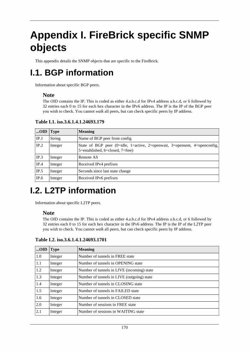
170
Appendix I. FireBrick specific SNMPobjects
This appendix details the SNMP objects that are specific to the FireBrick.
I.1. BGP informationInformation about specific BGP peers.
NoteThe OID contains the IP. This is coded as either 4.a.b.c.d for IPv4 address a.b.c.d, or 6 followed by32 entries each 0 to 15 for each hex character in the IPv6 address. The IP is the IP of the BGP peeryou wish to check. You cannot walk all peers, but can check specific peers by IP address.
Table I.1. iso.3.6.1.4.1.24693.179
...OID Type Meaning
IP.1 String Name of BGP peer from config
IP.2 Integer State of BGP peer (0=idle, 1=active, 2=openwait, 3=opensent, 4=openconfig,5=established, 6=closed, 7=free)
IP.3 Integer Remote AS
IP.4 Integer Received IPv4 prefixes
IP.5 Integer Seconds since last state change
IP.6 Integer Received IPv6 prefixes
I.2. L2TP informationInformation about specific L2TP peers.
NoteThe OID contains the IP. This is coded as either 4.a.b.c.d for IPv4 address a.b.c.d, or 6 followed by32 entries each 0 to 15 for each hex character in the IPv6 address. The IP is the IP of the L2TP peeryou wish to check. You cannot walk all peers, but can check specific peers by IP address.
Table I.2. iso.3.6.1.4.1.24693.1701
...OID Type Meaning
1.0 Integer Number of tunnels in FREE state
1.1 Integer Number of tunnels in OPENING state
1.2 Integer Number of tunnels in LIVE (incoming) state
1.3 Integer Number of tunnels in LIVE (outgoing) state
1.4 Integer Number of tunnels in CLOSING state
1.5 Integer Number of tunnels in FAILED state
1.6 Integer Number of tunnels in CLOSED state
2.0 Integer Number of sessions in FREE state
2.1 Integer Number of sessions in WAITING state

FireBrick specific SNMP objects
171
2.2 Integer Number of sessions in OPENING state
2.3 Integer Number of sessions in NEGOTIATING state
2.4 Integer Number of sessions in AUTH-PENDING state
2.5 Integer Number of sessions in STARTED state
2.6 Integer Number of sessions in LIVE state
2.7 Integer Number of sessions in ACCT-PENDING state
2.8 Integer Number of sessions in CLOSING state
2.9 Integer Number of sessions in CLOSED state
2.10 Integer Number of session negotiation slots free
IP.1 String The login name
IP.2 String The host name
IP.3 Integer Number of incoming tunnels
IP.4 Integer Number of outgoing tunnels
IP.5 Integer Seconds since oldest live tunnel connected
IP.6 Integer Number of live tunnels
IP.7 Integer Number of sessions
I.3. VoIP informationVoice over IP services information.
Table I.3. iso.3.6.1.4.1.24693.5060
...OID Type Meaning
1 Integer Number of active call legs
2 Integer Number of RADIUS based incoming registrations
3.n.1 String Name of carrier n
3.n.2 Integer Number of call legs for carrier n
3.n.3 Integer Number of connected call legs for carrier n
4.n.1 String Name of telephone n
4.n.2 Integer Number of call legs for telephone n
4.n.3 Integer Number of connected call legs for telephone n

172
Appendix J. Command line referenceJ.1. General commands
J.1.1. Trace off
troff
Stop interactive logging to this CLI session, lasts until logout or tron.
J.1.2. Trace on
tron
Restart interactive logging to this CLI session. Some types of logging can be set to log to console which showson the CLI.
J.1.3. Uptime
uptimeshow uptime
Shows how long since the FB2900 restarted.
J.1.4. General status
show status
Shows general status information, including uptime, who owns the FireBrick, etc. This is the same as the Statuson the web control pages.
J.1.5. Memory usage
show memory
Shows memory usage summary.
J.1.6. Process/task usage
show tasks
Shows internal task list. This is mainly for diagnostics purposes.
J.1.7. Login
login
Normally when you connect you are prompted for a username and password. If this is incorrect you can usethe login to try again.

Command line reference
173
J.1.8. Logout
logoutquitexit
You can also use Ctrl-D to exit, or close the connection (if using telnet)
J.1.9. See XML configuration
show runshow configuration
Dumps the full XML configuration to the screen
J.1.10. Load XML configuration
import configuration
You then send the XML configuration, ending with a blank line. You would not normally import a configurationusing this command, as you can use the web interface, and tools like curl to load configtations. This commandis provided as a last resort for emergency use, so use with care.
J.1.11. Show profile status
show profiles
Shows profiles and current status.
J.1.12. Enable profile control switch
enable profile <string>
Turns a named profile control switch on.
J.1.13. Disable profile control switch
disable profile <string>
Turns a named profile control switch off.
J.1.14. Show RADIUS servers
show radiusshow radius <IPAddr>
Shows details of RADIUS servers currently in use
J.1.15. Show DNS resolvers
show dns

Command line reference
174
Shows current DNS resolver list and status.
J.2. Networking commands
J.2.1. Subnets
show subnetsshow subnet <integer>
You can list all current subnets, or details of a specific subnet. This shows the same information as the webstatus pages for subnets.
J.2.2. Ping and trace
ping <IPNameAddr> [table=<routetable>] [source=<IPAddr>] [gateway=<IPAddr>] [flow=<unsignedShort>] [count=<positiveInteger>] [ttl=<unsignedByte>] [size=<unsignedShort>] [xml=<boolean>]traceroute <IPNameAddr> [table=<routetable>] [source=<IPAddr>] [gateway=<IPAddr>] [flow=<unsignedShort>] [count=<positiveInteger>] [ttl=<unsignedByte>] [size=<unsignedShort>] [xml=<boolean>]
This sends a series of ICMP echo requests (ping) to a specified destination and confirms a response is receivedand the round trip time. For the traceroute variant, the TTL/Hopcount is increased by one each time to showa series of response hops. There are a number of controls allowing you to fine tune what is sent. Obviouslyyou should only send from a source address that will return to the FB2900 correctly. You can also ask for theresults to be presented in an XML format.
Where possible, the reverse DNS name is shown next to replies, but there is (deliberately) no delay waitingfor DNS responses, so you may find it useful to run a trace a second time as results from the first attempt willbe cached.
J.2.3. Show a route from the routing table
show route <IPPrefix> [table=<routetable>]
Shows details of a route in the routing table. Where an individual IP is used, the route that would be used isshown, but if a specifiy prefix is used then that specific route is shown even if there may be more specificroutes in use.
J.2.4. List routes
show routes [<IPFilter>] [table=<routetable>]
Lists routes in the routing table, limited to those that match the filter if specified.
J.2.5. List routing next hops
show route nexthop [<IPAddr>]
List the next hop addresses currently in use and their status.

Command line reference
175
J.2.6. See DHCP allocations
show dhcp [<IP4Addr>] [table=<routetable>]
Shows DHCP allocations, with option to show details for specific allocation.
J.2.7. Clear DHCP allocations
clear dhcp [ip=<IP4Range>] [table=<routetable>]
Allows you to remove one or more DHCP allocations.
J.2.8. Lock DHCP allocations
lock dhcp ip=<IP4Addr> [table=<routetable>]
Locks a DHCP allocation. This stops the allocation being used for any other MAC address even if long expired.
J.2.9. Unlock DHCP allocations
unlock dhcp ip=<IP4Addr> [table=<routetable>]
Unlocks a DHCP allocation, allowing the address to be re-used if the expired.
J.2.10. Name DHCP allocations
name dhcp ip=<IP4Addr> [name=<string>] [table=<routetable>]
Allows you to set a name for a DHCP allocation, overridding the clientname that was sent.
J.2.11. Show ARP/ND status
show arpshow arp <IPAddr>
Shows details of ARP and Neighbour discovery cache.
J.2.12. Show VRRP status
show vrrp
Lists all VRRP in use and current status.
J.2.13. Send Wake-on-LAN packet
wol interface=<string> mac=<hexBinary>
Send a wake-on-LAN packet to a specific interface.

Command line reference
176
J.3. Firewalling commands
J.3.1. Check access to services
check access <IPAddr> [table=<routetable>]
Reports access control checks for a source address to various internal services. This is separate from anyfirewalling.
J.3.2. Check firewall logic
check firewall source-ip=<IPAddr> target-ip=<IPAddr>protocol=<unsignedByte> [source-port=<unsignedShort>][target-port=<unsignedShort>] [source-route-ip=<IPAddr>][table=<routetable>] [evil=<boolean>] [cug=<unsignedShort>]
Allows a detailed check of rule-sets and rules. This reports the rule-sets and rules that matched and the actionstaken.
J.4. USB/dongle commands
J.4.1. Show dongle connectoons
show dongleshow dongle <string>
Lists dongle data connections in use or shows details of a specific connection.
J.4.2. Reset USB interface and all attached devices
clear usb
Resets USB port and attached devices. This is useful if a device has locked up somehow.
J.4.3. Reset PPP/Dongle data connection
clear dongle <string>
Resets the data connection on a specified dongle. The dongle will then restart connection automatically.
J.5. L2TP commandsNoteThis command summary is not yet complete, please see www.firebrick.co.uk for details
J.6. BGP commandsNoteThis command summary is not yet complete, please see www.firebrick.co.uk for details

Command line reference
177
J.7. OSPF commandsNoteThis command summary is not yet complete, please see www.firebrick.co.uk for details
J.8. PPPoE commandsNoteThis command summary is not yet complete, please see www.firebrick.co.uk for details
J.9. VoIP commandsNoteThis command summary is not yet complete, please see www.firebrick.co.uk for details
J.10. Dongle/USB commandsNoteThis command summary is not yet complete, please see www.firebrick.co.uk for details
J.11. Advanced commandsSome commands are only available when logged in as a user set with DEBUG level access.
J.11.1. Panic
panic [<string>] [confirm=<string>]
This causes the FB2900 to crash, causing a panic event with a specified message. You need to specifyconfirm=yes for the command to work. This can be useful to test fallback scenarios by simulating a fatal error.Note that panic crash logs are emailed to the FireBrick support by default, so please use a meaningful string.e.g. panic "testing fallback" confirm=yes
J.11.2. Reboot
reboot [<unsignedInt>] [hard] [confirm=<string>]
A reboot is a more controlled shutdown and restart, unlike the panic command. The first argument is a blocknumber (see show flash contents) and forces reboot to run a specific software stored in flash. Normally thereboot will run the latest valid code. The hard option forces the reboot to clear the Ethernet ports and otherhardware so takes a couple of seconds. You must specify confirm=yes for this to work.
J.11.3. Screen width
set command screen width <unsignedInt>
This allows you to set the screen width.

Command line reference
178
J.11.4. Make outbound command session
start command session <IPAddr> [port=<unsignedShort>] [table=<routetable>]
This allows a reverse telnet connection to be made. A TCP connection is made to the IP address (and port)where a user can login. This can be useful where a firewall policy prevents incoming access to allow someoneto have access from outside, e.g. the FireBrick support team.
J.11.5. Show command sessions
show command sessions
The FB2900 can have multiple telnet connections at the same time. This lists all of the current connections.
J.11.6. Kill command session
kill command session <IPAddr>
You can kill a command session by IP address. This is useful if you know you have left a telnet connectedfrom somewhere else. Telnet sessions usually have a timeout, but this can be overridden in the configurationfor each user.
J.11.7. Flash memory list
show flash contents
Lists the content of flash memory - this includes various files such as software releases, configuration, andso on. Multiple copies are usually stored allowing you to delete a later version if needed, and roll-back to anolder version.
J.11.8. Delete block from flash
delete config <unsignedInt> [confirm=<string>]delete data <unsignedInt> [confirm=<string>]delete image <unsignedInt> [confirm=<string>]
Delete a block from flash memory. This cannot be undone. You have to specify the correct type of block, andspecify confirm=yes for the command to work.
J.11.9. Boot log
show boot log [<unsignedInt>]
Show log of recent boots. You can specify the number of bytes of recent log to show.
J.11.10. Flash log
show flash log [<unsignedInt>]
The logging system can log to flash for a permanent record. This is done automatically for some system eventsand when booting. You can specify the number of bytes of recent log to show..

179
Appendix K. Constant QualityMonitoring - technical details
The FireBrick provides constant quality monitoring. The main purpose of this is to provide a graphicalrepresentation of the performance of an interface or traffic shaper - typically used for broadband lines on L2TP.
• 100 second interval statistics available graphically as svg or png and in text as csv covering at least the last25 hours (one day)
• Loss latency stats where available (e.g. LCP echos on L2TP broadband lines) including minimum, average,and maximum latency for the 100 second sample, and percentage packet loss.
• Throughput stats where available (e.g. interfaces, shapers , L2TP broadband lines ) including average tx andrx rate for 100 second sample
Graphs can be loss/latency or throughput of both. A ping only system would only have loss/latency. An L2TPbroadband line has both. An interface or shaper normally has only throughput data.
K.1. Broadband back-haul providersWhen using the FB2900 as an LNS the CQM graphs are invaluable for diagnosing line faults. They are usefulto the ISP but also useful to the back-haul provider which is often a separate company (e.g. BT or Be). Werecommend that you consider providing access to graphs for live circuits and archived data to your back-haul provider when discussing faults with them. FireBrick are working with several ISPs to ensure back-haulproviders are aware of the CQM graphs and how to use them to assist in diagnosis.
K.2. Access to graphs and csvsGraphs can be accessed by http using the normal web management interface. This can be used as a direct linkfrom a web browser, or using common tools such as curl and wget.
The web management interface (services/http) define the port, and allowed user list and also a trusted IP accesslist. The CQM config defines a secret which is used to authorise untrusted access using an SHA1 hash in theURL.
All CQM URLs are in the /cqm/ path.
K.2.1. Trusted accessTo access a graph you simply need to request the URL that is the graph name, followed by the file extension.E.g. http://host:port/cqm/circuit.png.
Table K.1. File types
Extn Format
svg SVG image
png PNG image
csv COMMA separated values list
tsv TAB separated values list
txt SPACE separated values list
xml XML data

Constant Quality Monitoring- technical details
180
K.2.2. Dated informationWithout any date the data returned is the latest. This includes the last 24 to 25 hours.
You can display data for a specific date. This only makes sense for today, and during the first couple of hoursof the day you can get yesterday in full.
The syntax is that of a date first in the form YYYY-MM-DD/, e.g. http://host:port/cqm/YYYY-MM-DD/circuit.png.
K.2.3. Authenticated accessAuthenticate access requires a prefix of a hex sha1 string. e.g. http://host:port/cqm/longhexsha1/circuit.png orhttp://host:port/cqm/longhexsha1/YYYY-MM-DD/circuit.png.
The SHA1 is 40 character hex of the SHA1 hash made from the graph name, the date, and the http-secret. Thedate is in the form YYYY-MM-DD, and is today's date for undated access (based on local time).
This means a graph URL can be composed that is valid for a specific graph name for a specific day.
Note that an MD5 can also be used instead but the SHA1 is the preferred method.
K.3. Graph display optionsThe graphs can have a number of options which define the colours, text and layout. These are defined as httpform get attributes on the URL, e.g. http://host:port/cqm/circuit.png?H=a+heading.
Note that they can also be included in the path before the graph name, e.g. http://host:port/cqm/H=a+heading/circuit.png in which case they can be separated by / rather than &.
The attributes are processed in order.
NoteThese attributes apply to both png and svg output, however it is also possible to override the svg styleand use a css style sheet from a URL instead. In such cases none of the colour settings from the configor the graph URL will apply. See an actual svg output for classes that are used in the graphs.
K.3.1. Scaleable Vector GraphicsThe graphs are available in PNG and SVG. We recommend using SVG graphs.
The SVG version is usually a lot quicker to load, and has a lot more detail. T works well on high resolutionmonitors and devices that allow scaling (such as mobile phones).
The SVG is designed to allow some post processing or manipulation with specific paths for each part of thegraph, such as "tx", "rx", "min", "ave", "max", etc. These data paths are also presented using a fixed scale,and then scaled and cropepd by a wrapping group. This allows tools to merge graphs from difference sourcesand maintain scales, or allow scales to be changed later. If you actually want access to the raw data, then youshould use the XML output.
There is an option for an external CSS to be referenced, rather than local style based on the config settings.This allows even more control and flexability for display.
There is also an option to include an overlay providing tool tip (title) information for each 100 second sample.This makes for much larger files though.

Constant Quality Monitoring- technical details
181
K.3.2. Data pointsThe data point controls can be included as either fieldname or fieldname=colour. To make a valid URL eitherescape the # prefix or omit it. If any of these are included, then only those that are included are shown. If justfieldname is specified then the default colour is applied. The text on the right shows what fields are includedand their colour key.
Table K.2. Colours
Key Colour
M Defines colour for minimum latency
A Defines colour for average latency
X Defines colour for max latency
U Defines colour for upload rate
D Defines colour for download rate
S Defines colour for sent echos
J Defines colour for rejected echos
F Defines colour for failed (no response) echos
O Defines colour for off-line
K.3.3. Additional textAdditional text is shown on the graph based on the values in the configuration if not specified. There are 4 lineson the top left in small text and two heading lines top right in large text.
Table K.3. Text
Key Text
z Clean output, clears all additional text fields
Z Clean and clear, as z but also sets inside background and off-line colours to transparent so graphsare easy to merge with those other LNSs
C Line 1 top left text, default if not set in config is system name
c Line 2 top left text
N Line 3 top left text
n Line 4 top left text
H Main heading text, default if not set in config is graph name
h Sub heading text
Note that Z and z do not normally have any arguments, but if they do, then it sets the SVG CSS to use, e.g.z(mystyle.css) but an empty string, e.g. z(), will use the standard config based style. Setting Z forcesno style and no css so parent document can set styles.
K.3.4. Other colours and spacingColours can be in the form of RGB, RRGGBB, RGBA, RRGGBBAA defining red/green/blue/alpha, or somesimple colour names.
Table K.4. Text
Key Meaning

Constant Quality Monitoring- technical details
182
L Defines a number of pixels to be provided on the left of the graph. Bandwidth and scale axis shownbased on space provided left and right.
R Defines a number of pixels to be provided on the right of the graph. Bandwidth and scale axis isshown based on space provided left and right.
T Defines a number of pixels to be provided on the top of the graph. Time axes is show based onspace at top and bottom.
B Defines a number of pixels to be provided on the bottom of the graph. Time axes is show basedon space at top and bottom.
Y Defines Y bandwidth scale starting point (0 is lowest, 1 is next, etc).
y Defines Y ms scale max level (in ms).
I Defines colour for graticule
i Defines colour for axis lines
g Defines colour for background within axis
G Defines colour for background outside axis
W Defines colour for writing (text)
E Mouseover title text in svg (depending on browser, this may only work if you embed the svg in apage rather than as img tag)
e No mouseover title text in svg
K.4. Overnight archivingThe system is designed to make it easy to archive all graphs or svg, png, xml, etc files over night. The graphshold 1000 data points, which is 27 hours 46 minutes. This means you can access a full day's data for the previousday in the first 3 hours 46 minutes of the new day (2 hours 46 or 4 hours 46 when clocks change in previousday). As such it is recommended that over night archiving is done of the previous day just after midnight.
The recommended command to run just after midnight is wget --quiet --no-parent --mirrorhttp://host:port/cqm/`date +%F -dyesterday`/z/ as this will create a directory for theserver, cqm, date, and z, and then the files. The use of z clears text off the graphs to make them clean. UsingZ does SVG with no style included, so expecting to be used with a separate style sheet when presented.
K.4.1. Full URL formatThe full URL format allows several variations. These are mainly to allow sensible directory structures inovernight archiving.
Table K.5. URL formats
URL Meaning
/cqm/ All CQM URLs start with this
32-hex-characters/
Optional authentication string needed for untrusted access. Can be used with trusted accessto test the authentication is right
YYYY-MM-DD/
Optional date to restrict output. Can also be in the form YYYY/MM/DD, YYYY-MM/DD,YYYY/MM-DD if preferred. Can also have /HH or -HH on the end to get data for justone hour, and /HH-HH, or -HH-HH on the end for a specific range of hours. Can end /HH:MM:SS or -MM:MM:SS for data for one hour from a specific time.
options/ Optional graph colour control options. Useful when extracting a list of images as the all musthave the same options as the list is just graphname.png as a relative link thereby ensuring allgraphs appear in this directory. The options list can include / separators rather & separatorsto make apparent subdirectories.

Constant Quality Monitoring- technical details
183
ext/ The file extension can be included on the end of the options, this is used only for makingthe index of all graphs for that type (see below)
graphname Graph name. For XML this can be just * to produce one XML file with all graphs.
.ext Extension for file type required
?options Options can alternatively be included as a html form get field list
Where no graph name or ext are provided, i.e. the index page of a directory then an html page is served. Anext/ can be included after any options to make a list of files of that type. Otherwise the index is an html pageexplaining the options.
A blank graph is available by accessing simply .png (i.e. no graph name).
An xml list of all graphs is available as .xml.
A csv list of graph name and score is available as .csv and similarly for txt and tsv.
A special case exists for extracting the xml files for all graphs in one request, using the name *.xml.
K.4.2. load handlingThe graphs and csv files are generated on the fly, and only one is generated at a time. Connection requestsare queued. As part of the normal web management system, the trusted IPs queue is always processed firstso constant access from untrusted sources will not stop access from trusted sources. If the queue is full theconnection is not accepted. The most load applies when archiving, but tools like wget fetch one linked file ata time which is ideal.
K.5. Graph scoresGraphs are scored based on settings in the config. Each 100 second sample has a score which is included inthe csv and xml lists for any graph. The score is also totalled for a graph as a whole and included in the csvand xml list of all graphs. This total is done by multiplying the last score by 864, the previous by 863, and soon for the previous 24 hours.
K.6. Creating graphs, and graph namesGraph names are text and up to 20 characters. Only letters, numbers, @, -, and . are allowed. All other charactersare removed. It is recommended that names complying with this are used. Any graph name that you try and usethat is too long will be replaced with one that uses part of the name and a hash to try and ensure a consistentunique graph name is applied.
Graphs can be defined in some configuration settings such as interface names.
Graphs can also be created dynamically in some cases, e.g. L2TP based graphs are made based on theChargeable-User-Id, Calling-Station-Id or User-Name for a connected line, and so can be defined from theRADIUS authentication response. It is recommended that the circuit ID is used where available, e.g. from BTplatform RADIUS.
Whilst the FB2900 can manage thousands of graphs, new graphs will not be created if memory is not available.

184
Appendix L. Hashed passwordsThe configuration XML includes passwords and OTP seeds encoded using hashes, this makes it impossible toextract the password from the config.
CautionIt is still important to keep the configuration hashes safe, as someone could use the hashes to trymillions of passwords off-line before trying to log in to a FireBrick. For this reason it is also importantto use good passwords that cannot be guessed, and are not simply made from normal dictionary words.
L.1. Password hashingThe user section of the configuration has a password field. You will note that is it mostly a lot ofhexadecimal data, the hash, as described below.
It is possible to put a new password in to the configuration directly in the password field and save the config.It will be hashed automatically so when you access the configuration you will see the hashed version in thepassword field. However, this is not possible if you also have an otp-seed defined, unless also setting anew otp-seed field or removing it. For this reason there is also a web page to allow a user to change theirpassword.
TipWe recommend you use the web page to change the password for a user, and in fact, that the userthemselves do this, so as the administrator does not know the password.
The FireBrick supports a number of hash functions for passwords, but on any successful login may changethe config to use the current preferred password hash function. This allows FireBrick to move to more securepassword hash functions in future whilst maintaining backward compatibility.
If making a configuration file independantly you can generate the hashes yourself in most cases. The supportedhash codings are as follows. For salted hashes, the salt is the additional bytes after the number of bytes forthe hash.
• FB105#[10 bytes of hex]: A legacy for the old FB105 password hashing, used by the FB105 conversion tool.
• MD5#[16 to 19 bytes of hex]: The first 16 bytes are an MD5 hash of the password appended with up to 3bytes of salt.
• SHA1#[20 to 31 bytes of hex]: The first 20 bytes are an SHA1 hash of the password appended with up to11 bytes of salt.
• SHA256#[32 to 47 bytes of hex]: The first 32 bytes are an SHA256 hash of the password appended withup to 15 bytes of salt.
The preferred hash is SHA256 with 15 bytes of salt. However, this may change in the future to more robustpassword functions.
L.1.1. SaltA hash function simply takes some data, and generates a hash from it - as a one-way process. This ensures that,given the hash, you cannot work out the original string (normally a password).
However, a particular string (e.g. password) always generates the same hash. As such it is possible for peopleto have huge tables of pre-calculated hashes for common passwords and dictionary words. This allows such(poor) passwords to simply be looked up from a hash.

Hashed passwords
185
There is also the problem that two people using the same password end up with the same hash, and so can seethat the other person is using the same password.
To solve this, we use salt. Salt is simply a number of random bytes. These are appended to the end of theoriginal data before making a hash. This means the hash is not just of a password, but of a password and arandom string (the salt).
The salt is stored, along with the hash. This means it is possible to check a password by appending the salt andcalculating the hash and checking it matches the stored hash.
The password hashes all have an option of salt. If making your own password we recommend the latest hashmethod and as much salt as allowed. The salt should be random.
The OTP seed is scrambled using a separate salt on the same password, else the encryption would simply beusing the hash you see in the password field, which would not be very secure!
L.2. One Time Password seed hashingThe configuration also holds the OTP seed used for One Time Password authenticator codes. However, this isstored in an encrypted format so that the seed cannot be accessed. This is especially important as the OTP seedallows the OTP sequence to be generated, not simply checked (as is the case with a password hash).
The issue with encrypting the OTP seed is that the FireBrick has to be able to decrypt it so as to check the OTPsequence used. To ensure that no secret encryption key is embedded in the FireBrick firmware, the encryptionis done using the users password. Once again, this means that it is important to have a good password. Thissystem means that the password hash and encrypted OTP seed can be saved, and restored and even moved toanother FireBrick configuration if needed without ever having to know the seed or password itself.
CautionThis means that if someone knows (or finds out) the password and has access to the configuration filethen they could extract the OTP seed and use it to log in, even though they do not have the OTP device/app. For this reason it is important to keep the password and OTP seed data in the configuration safe.
You can enter a new OTP seed in to the otp-seed field in the config, if you wish. This should be a BASE32string (which is the common format for usch strings). If the seed is for 60 second periods not the default 30then append /60. If the seed is not for 6 digit codes, you can add a time (/30 or /60) and then /N where N is thenumber of digits (4-8). Once saved you will see the seed changes to a base64 coded string. If you do this youshould immediately test the authenticator by having the user log in. Until then, the seed is not encrypted in theconfiguration and could be recovered. Once you have logged in, if you normally save / archive the config, thiswould be a good time to ensure you have the encrypted version saved.
NoteThe old OTP system used this field (called just otp) as the serial number of a separately stored OTPseed that was not held in the config. This is no longer supported, but if you have such a configurationyou may see simply the serial number in this field until the user first logs in and it is replaced withthe encrypted OTP seed.
Once encoded the format is a # followed by base64 coding of a series of bytes. If making a configuration fileindependantly then you can generate the seed data directly if you wish. The format is as follows.
• 1 byte: total length of data including this byte
• 1 byte: seed type 0xDT where D=digits and T is time in 10 seconds, so 0x63 is normal for 6 digits every30 seconds.
• 1 byte: hash type, 0-15 means not encrypted but space for up to 15 bytes of salt. 32-47 means SHA256 hashencrypted with up to 15 bytes of salt.

Hashed passwords
186
• N bytes: The OTP seed XOR with the hash made from the password with salt appended. If seed is longerthan hash then only initial hash length bytes are XOR'd.
• S bytes: Seed bytes, should be random.
• 1 byte: 2's complement checksum making sum of all bytes 0x00.

187
Appendix M. Configuration ObjectsThis appendix defines the object definitions used in the FireBrick FB2900 configuration. Copyright © 2008-16FireBrick Ltd.
M.1. Top level
M.1.1. config: Top level configThe top level config element contains all of the FireBrick configuration data.
Table M.1. config: Attributes
Attribute Type Default Description
ip IPAddr - Config store IP address
patch integer - Internal use, for s/w updates that changeconfig syntax
serial string - Serial number
timestamp dateTime - Config store time, set automatically whenconfig is saved
version string - Code version
who string - Config store username
Table M.2. config: Elements
Element Type Instances Description
bgp bgp Optional, up to 100 BGP config
bgp-filter namedbgpmap Optional, unlimited Mapping and filtering rules for use withBGP peers
blackhole blackhole Optional, unlimited Black hole (dropped packets) networks
cqm cqm Optional Constant Quality Monitoring config
dhcp-relay dhcp-relay Optional, unlimited DHCP server settings for remote / relayedrequests
eap eap Optional, unlimited User access control via EAP
ethernet ethernet Optional, unlimited Ethernet port settings
etun etun Optional, unlimited Ether tunnel (RFC3378)
fb105 fb105 Optional, up to 255 FB105 tunnel settings
interface interface Optional, up to 8192 Ethernet interface (port-group/vlan) andsubnets
ip-group ip-group Optional, unlimited Named IP groups
ipsec-ike ipsec-ike Optional IPsec connection settings
l2tp l2tp Optional L2TP settings
link-activity link-activity Optional, unlimited Port LED activity settings
log log Optional, up to 50 Log target controls
loopback loopback Optional, unlimited Extra local addresses

Configuration Objects
188
network network Optional, unlimited Locally originated networks
nowhere blackhole Optional, unlimited Dead end (icmp error) networks
ospf ospf Optional, unlimited OSPF config
ping ping Optional, up to 100 Base ping graph settings
port portdef Optional, up to 8 Port grouping and naming
ppp pppoe Optional, up to 10 PPPoE settings
profile profile Optional, unlimited Control profiles
route route Optional, unlimited Static routes
route-override route-override Optional, unlimited Routing override rules
rule-set rule-set Optional, unlimited Firewall/mapping rules
sampling sampling Optional Sampling parameters
services services Optional General system services
shaper shaper Optional, unlimited Named traffic shapers
system system Optional System settings
usb usb Optional USB and 3G/dongle settings
user user Optional, unlimited Admin users
voip voip Optional VoIP config
M.2. Objects
M.2.1. system: System settingsThe system settings are the top level attributes of the system which apply globally.
Table M.3. system: Attributes
Attribute Type Default Description
acme-directory string https://acme-v02.api.letsencrypt.org/directory
ACME server directory
acme-hostname List of string - Public hostname(s) for FireBrick for https
acme-keygen boolean true Automatically obtain private keys asneeded
acme-renew positiveInteger 30 Renewal before expiry (days)
acme-terms-agreed-email
string - Put your email if you agree CA terms
busy-threshold unsignedInt 200 Max non-idle time before damping eth rx(millisec)
comment string - Comment
contact string - Contact name
cpu-int-reserved (unsignedByte0-100) percentage
90 Min percentage of CPU earmarked for intprocessing
email string - Contact email
eth-rx-qsize unsignedInt 256 Size of eth driver Rx queue
eth-tx-qsize unsignedInt 512 Size of eth driver Tx queue

Configuration Objects
189
home-status boolean true Port status on home page
intro string - Home page text
location string - Location description
log NMTOKEN Web/console Log system events
log-acme NMTOKEN - Log ACME
log-acme-debug NMTOKEN - Log ACME debug
log-acme-error NMTOKEN - Log ACME errors
log-config NMTOKEN Web/Flash/console Log config load
log-debug NMTOKEN Not logging Log system debug messages
log-error NMTOKEN Web/Flash/console Log system errors
log-eth NMTOKEN Web/console Log Ethernet messages
log-eth-debug NMTOKEN Not logging Log Ethernet debug
log-eth-error NMTOKEN Web/Flash/console Log Ethernet errors
log-panic NMTOKEN Web logs Log system panic messages
log-route-nexthop NMTOKEN Not logged Log next hop changes
log-stats NMTOKEN Not logging Log one second stats
log-tcp-debug NMTOKEN Not logging Log TCP stack debug messages
mirror-led-brightness
(unsignedByte0-100) percentage
100 Brightness of mirror side LEDs
name string - System hostname
nat64 IP6Prefix - IPv6 NAT6/4 mapping prefix (deprecated,use firewall rules)
nat64-source IP4Addr - IPv6 NAT6/4 return IPv4 (deprecated, usefirewall rules)
port-led-brightness (unsignedByte0-100) percentage
100 Brightness of port side LEDs
port-status boolean true Live port LEDs on status
pre-reboot-url string - URL to GET prior to s/w reboot (typicallyto warn nagios)
soft-watchdog boolean false Debug - use only if advised; do not use onan unattended FireBrick
source string - Source of data, used in automated configmanagement
status-led-colour Colour green Default status LED colour
sw-update autoloadtype factory Load new software automatically
sw-update-profile NMTOKEN - Profile name for when to load new s/w
table (unsignedByte 0-99)routetable
0 Routing table number for system functions(s/w updates, etc)
Table M.4. system: Elements
Element Type Instances Description
link link Optional, unlimited Home page links

Configuration Objects
190
M.2.2. link: Web linksLinks to other web pages
Table M.5. link: Attributes
Attribute Type Default Description
comment string - Comment
name string - Link name
profile NMTOKEN - Profile name
source string - Source of data, used in automated configmanagement
text string - Link text
url string - Link address
M.2.3. user: Admin usersUser names, passwords and abilities for admin users
Table M.6. user: Attributes
Attribute Type Default Description
allow List ofIPNameRange
- Restrict logins to be from specific IPaddresses
comment string - Comment
config config-access full Config access level
full-name string - Full name
level user-level ADMIN Login level
name (NMTOKEN)username
Not optional User name
otp-seed OTP - OTP seed (do not edit by hand)
password Password Not optional User password
profile NMTOKEN - Profile name
source string - Source of data, used in automated configmanagement
table (unsignedByte 0-99)routetable
0 Restrict login to specific routing table
timeout duration 5:00 Login idle timeout (zero to stay logged in)
M.2.4. eap: User access controlled by EAPIdentities, passwords and access methods for access controlled with EAP
Table M.7. eap: Attributes
Attribute Type Default Description
comment string - Comment
full-name string - Full name
methods Set of eap-method Not optional Allowed methods

Configuration Objects
191
name string Not optional User or account name
password Secret Not optional User password
profile NMTOKEN - Profile name
source string - Source of data, used in automated configmanagement
subsystem eap-subsystem Not optional Access controlled subsystem
M.2.5. log: Log target controlsNamed logging target
Table M.8. log: Attributes
Attribute Type Default Description
colour Colour - Colour used in web display
comment string - Comment
console boolean - Log immediately to console
flash boolean - Log immediately to slow flash memory(use with care)
jtag boolean - Log immediately jtag (development useonly)
name NMTOKEN Not optional Log target name
profile NMTOKEN - Profile name
source string - Source of data, used in automated configmanagement
Table M.9. log: Elements
Element Type Instances Description
email log-email Optional, unlimited Email settings
syslog log-syslog Optional, unlimited Syslog settings
M.2.6. log-syslog: Syslog logger settingsLogging to a syslog server
Table M.10. log-syslog: Attributes
Attribute Type Default Description
comment string - Comment
facility syslog-facility LOCAL0 Facility setting
port unsignedShort 514 Server port
profile NMTOKEN - Profile name
server IPNameAddr Not optional Syslog server
severity syslog-severity NOTICE Severity setting
source string - Source of data, used in automated configmanagement
source-ip IPAddr - Use specific source IP
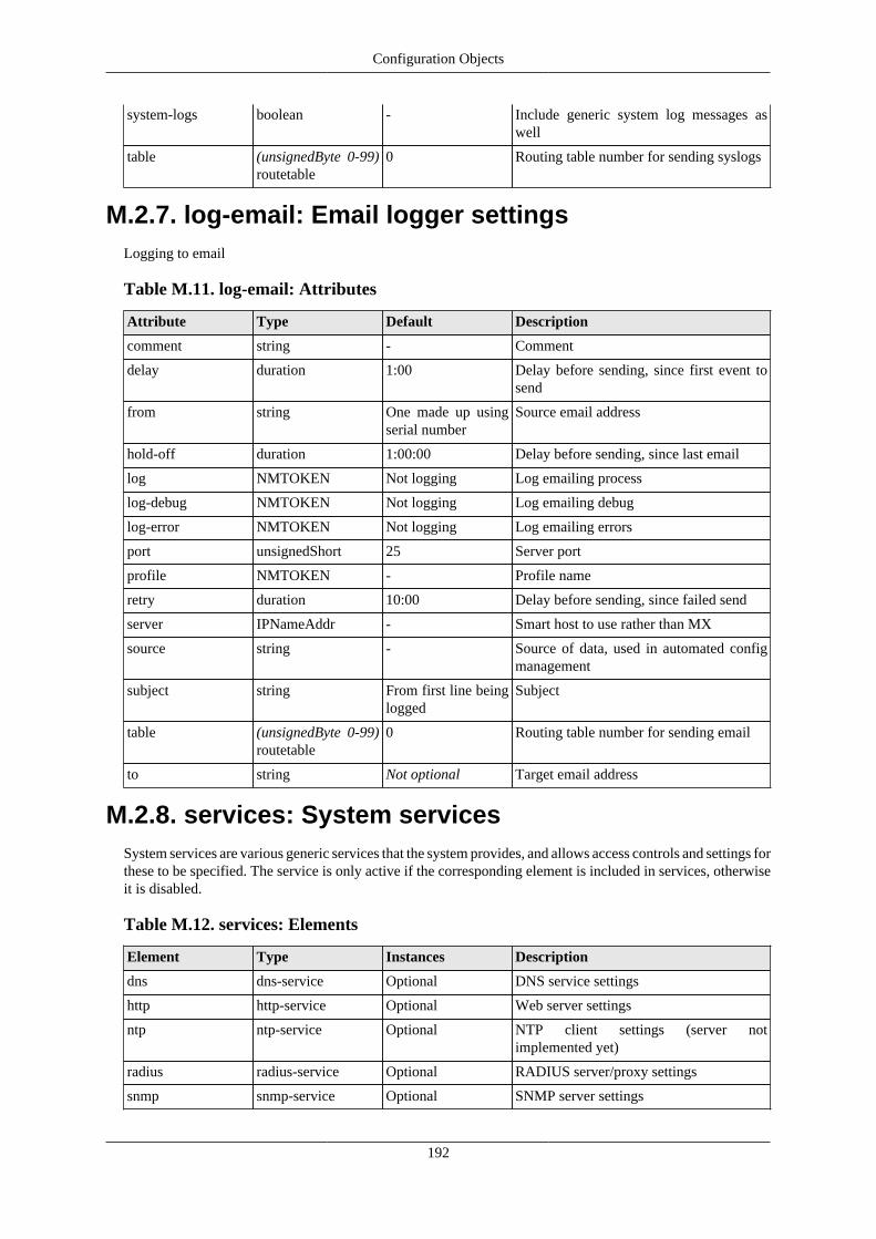
Configuration Objects
192
system-logs boolean - Include generic system log messages aswell
table (unsignedByte 0-99)routetable
0 Routing table number for sending syslogs
M.2.7. log-email: Email logger settingsLogging to email
Table M.11. log-email: Attributes
Attribute Type Default Description
comment string - Comment
delay duration 1:00 Delay before sending, since first event tosend
from string One made up usingserial number
Source email address
hold-off duration 1:00:00 Delay before sending, since last email
log NMTOKEN Not logging Log emailing process
log-debug NMTOKEN Not logging Log emailing debug
log-error NMTOKEN Not logging Log emailing errors
port unsignedShort 25 Server port
profile NMTOKEN - Profile name
retry duration 10:00 Delay before sending, since failed send
server IPNameAddr - Smart host to use rather than MX
source string - Source of data, used in automated configmanagement
subject string From first line beinglogged
Subject
table (unsignedByte 0-99)routetable
0 Routing table number for sending email
to string Not optional Target email address
M.2.8. services: System servicesSystem services are various generic services that the system provides, and allows access controls and settings forthese to be specified. The service is only active if the corresponding element is included in services, otherwiseit is disabled.
Table M.12. services: Elements
Element Type Instances Description
dns dns-service Optional DNS service settings
http http-service Optional Web server settings
ntp ntp-service Optional NTP client settings (server notimplemented yet)
radius radius-service Optional RADIUS server/proxy settings
snmp snmp-service Optional SNMP server settings

Configuration Objects
193
telnet telnet-service Optional Telnet server settings
M.2.9. http-service: Web service settingsWeb management pages
Table M.13. http-service: Attributes
Attribute Type Default Description
access-control-allow-origin
string - Additional http header
allow List ofIPNameRange
Allow fromanywhere
List of IP ranges from which service can beaccessed
allow-acme boolean true Allow limited port 80 http access forACME during renewal
certlist List of NMTOKEN use any suitable Certificate(s) to be used for https sessions
comment string - Comment
content-security-policy
string - Additional http header
css-url string - Additional CSS for web control pages
https-port unsignedShort 443 Service port for https access
local-only boolean true Restrict access to locally connectedEthernet subnets only
log NMTOKEN Not logging Log events
log-debug NMTOKEN Not logging Log debug
log-error NMTOKEN Log as event Log errors
mode http-mode redirect-to-https-if-acme
Security mode
port unsignedShort 80 Service port for http access
profile NMTOKEN - Profile name
referrer-policy string no-referrer Additional http header
self-sign boolean true Create self signed certificate for https whennecessary
source string - Source of data, used in automated configmanagement
table (unsignedByte 0-99)routetable
0 Routing table number
trusted List ofIPNameRange
- List of allowed IP ranges from whichadditional access to certain functions isavailable
x-content-type-options
string nosniff Additional http header
x-frame-options string SAMEORIGIN Additional http header
x-xss-protection string 1; mode=block Additional http header
M.2.10. dns-service: DNS service settingsDNS forwarding resolver service

Configuration Objects
194
Table M.14. dns-service: Attributes
Attribute Type Default Description
allow List ofIPNameRange
Allow fromanywhere
List of IP ranges from which service can beaccessed
auto-dhcp boolean - Forward and reverse DNS for names inDHCP using this domain
caching boolean true Cache relayed DNS entries locally
comment string - Comment
domain string - Our domain
fallback boolean true For incoming requests, if no server inrequired table, relay to any DNS available
local-only boolean true Restrict access to locally connectedEthernet subnets only
log NMTOKEN Not logging Log events
log-debug NMTOKEN Not logging Log debug
log-error NMTOKEN Log as event Log errors
profile NMTOKEN - Profile name
resolvers List of IPAddr - Recursive DNS resolvers to use
resolvers-table (unsignedByte 0-99)routetable
as table / 0 Routing table for specified resolvers
source string - Source of data, used in automated configmanagement
table (unsignedByte 0-99)routetable
0 Routing table number
Table M.15. dns-service: Elements
Element Type Instances Description
block dns-block Optional, unlimited Fixed local DNS host blocks
host dns-host Optional, unlimited Fixed local DNS host entries
M.2.11. dns-host: Fixed local DNS host settingsDNS forwarding resolver service
Table M.16. dns-host: Attributes
Attribute Type Default Description
comment string - Comment
ip List of IPAddr Our IP IP addresses to serve (or our IP if omitted)
name List of string Not optional Host names (can use * as a part of a domain)
profile NMTOKEN - Profile name
restrict-interface List of NMTOKEN - Only apply on certain interface(s)
restrict-to List ofIPNameRange
- List of IP ranges to which this is served
reverse boolean - Map reverse DNS as well

Configuration Objects
195
source string - Source of data, used in automated configmanagement
table (unsignedByte 0-99)routetable
any Routing table applicable
ttl unsignedInt 60 Time to live
M.2.12. dns-block: Fixed local DNS blocksDNS forwarding resolver service
Table M.17. dns-block: Attributes
Attribute Type Default Description
comment string - Comment
name List of string Not optional Host names (can use * as a part of a domain)
profile NMTOKEN - Profile name
restrict-interface List of NMTOKEN - Only apply on certain interface(s)
restrict-to List ofIPNameRange
- List of IP ranges to which this is served
source string - Source of data, used in automated configmanagement
table (unsignedByte 0-99)routetable
any Routing table applicable
ttl unsignedInt 60 Time to live
M.2.13. radius-service: RADIUS service definitionRADIUS server and proxy definitions
Table M.18. radius-service: Attributes
Attribute Type Default Description
acct-port unsignedShort 1813 Accounting UDP port
auth-port unsignedShort 1812 Authentication UDP port
authenticator boolean - Require message authenticator
backup-ip List of IPNameAddr - Target IP(s) or hostname for backup L2TPconnection
class string - Class field to send
comment string - Comment
control-port unsignedShort 3799 Control UDP port (CoA/DM)
dummy-ip boolean true Send dummy framed IP response
erx-tunnel-switch-profile
string - Juniper attribute 91
erx-tunnel-virtual-router
string - Juniper attribute 8
erx-virtual-router-name
string - Juniper attribute 1 (Also SIN502 Context-Name)
log NMTOKEN Not logging Log events

Configuration Objects
196
log-debug NMTOKEN - Log debug
log-error NMTOKEN Log as event Log errors
nsn-conditional boolean - Only send NSN settings if username is notsame as calling station id
nsn-tunnel-override-username
unsignedByte - Additional response for GGSN usage
nsn-tunnel-user-auth-method
unsignedInt - Additional response for GGSN usage
order radiuspriority - Priority tagging of endpoints sent
profile NMTOKEN - Profile name
relay-ip List of IPAddr - Address to copy RADIUS request
relay-port unsignedShort 1812 Authentication UDP port for copyRADIUS request
relay-table (unsignedByte 0-99)routetable
- Routing table number for copy of RADIUSrequest
secret Secret - Shared secret for RADIUS requests(needed for replies)
source string - Source of data, used in automated configmanagement
tagged boolean - Tag all attributes that can be
target-hostname string - Hostname for L2TP connection
target-ip List of IPNameAddr - Target IP(s) or hostname for primary L2TPconnection
target-secret Secret - Shared secret for L2TP connection
test List of IPAddr - List of IPs that must have routing for thistarget to be valid (deprecated)
tunnel-assignment-id
string - Tunnel Assignment ID to send
tunnel-client-return boolean - Return tunnel client as radius IP
Table M.19. radius-service: Elements
Element Type Instances Description
match radius-service-match
Optional, unlimited Matching rules for specific responses
server radius-server Optional, unlimited RADIUS server settings
M.2.14. radius-service-match: Matching rules forRADIUS service
Rules for matching incoming RADIUS requests
Table M.20. radius-service-match: Attributes
Attribute Type Default Description
allow List ofIPNameRange
- Match source IP address of RADIUSrequest

Configuration Objects
197
authenticator boolean - Require message authenticator
backup-ip List of IPNameAddr - Target IP(s) or hostname for backup L2TPconnection
called-station-id List of string - One or more patterns to match called-station-id
calling-station-id List of string - One or more patterns to match calling-station-id
class string - Class field to send
comment string - Comment
dummy-ip boolean true Send dummy framed IP response
erx-tunnel-switch-profile
string - Juniper attribute 91
erx-tunnel-virtual-router
string - Juniper attribute 8
erx-virtual-router-name
string - Juniper attribute 1 (Also SIN502 Context-Name)
ip List ofIPNameRange
- Match target IP address of RADIUSrequest
name string - Name
nas-ip List ofIPNameRange
- Match NAS-IP address in RADIUS request
nsn-conditional boolean - Only send NSN settings if username is notsame as calling station id
nsn-tunnel-override-username
unsignedByte - Additional response for GGSN usage
nsn-tunnel-user-auth-method
unsignedInt - Additional response for GGSN usage
order radiuspriority - Priority tagging of endpoints sent
profile NMTOKEN - Profile name
relay-ip List of IPAddr - Address to copy RADIUS request
relay-port unsignedShort 1812 Authentication UDP port for copyRADIUS request
relay-table (unsignedByte 0-99)routetable
- Routing table number for copy of RADIUSrequest
secret Secret - Shared secret for RADIUS requests(needed for replies)
source string - Source of data, used in automated configmanagement
stop boolean true Stop checking if this matches
tagged boolean - Tag all attributes that can be
target-hostname string - Hostname for L2TP connection
target-ip List of IPNameAddr - Target IP(s) or hostname for primary L2TPconnection
target-secret Secret - Shared secret for L2TP connection
test List of IPAddr - List of IPs that must have routing for thistarget to be valid (deprecated)
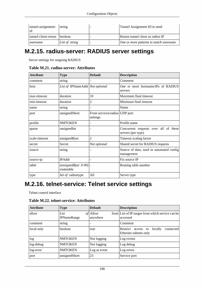
Configuration Objects
198
tunnel-assignment-id
string - Tunnel Assignment ID to send
tunnel-client-return boolean - Return tunnel client as radius IP
username List of string - One or more patterns to match username
M.2.15. radius-server: RADIUS server settingsServer settings for outgoing RADIUS
Table M.21. radius-server: Attributes
Attribute Type Default Description
comment string - Comment
host List of IPNameAddr Not optional One or more hostname/IPs of RADIUSservers
max-timeout duration 10 Maximum final timeout
min-timeout duration 2 Minimum final timeout
name string - Name
port unsignedShort From services/radiussettings
UDP port
profile NMTOKEN - Profile name
queue unsignedInt - Concurrent requests over all of theseservers (per type)
scale-timeout unsignedByte 2 Timeout scaling factor
secret Secret Not optional Shared secret for RADIUS requests
source string - Source of data, used in automated configmanagement
source-ip IPAddr - Fix source IP
table (unsignedByte 0-99)routetable
- Routing table number
type Set of radiustype All Server type
M.2.16. telnet-service: Telnet service settingsTelnet control interface
Table M.22. telnet-service: Attributes
Attribute Type Default Description
allow List ofIPNameRange
Allow fromanywhere
List of IP ranges from which service can beaccessed
comment string - Comment
local-only boolean true Restrict access to locally connectedEthernet subnets only
log NMTOKEN Not logging Log events
log-debug NMTOKEN Not logging Log debug
log-error NMTOKEN Log as event Log errors
port unsignedShort 23 Service port

Configuration Objects
199
profile NMTOKEN - Profile name
source string - Source of data, used in automated configmanagement
table (unsignedByte 0-99)routetable
0 Routing table number
M.2.17. snmp-service: SNMP service settingsThe SNMP service has general service settings and also specific attributes for SNMP such as community
Table M.23. snmp-service: Attributes
Attribute Type Default Description
allow List ofIPNameRange
Allow fromanywhere
List of IP ranges from which service can beaccessed
comment string - Comment
community string public Community string
local-only boolean false Restrict access to locally connectedEthernet subnets only
log NMTOKEN Not logging Log events
log-debug NMTOKEN Not logging Log debug
log-error NMTOKEN Log as event Log errors
port unsignedShort 161 Service port
profile NMTOKEN - Profile name
source string - Source of data, used in automated configmanagement
table (unsignedByte 0-99)routetable
0 Routing table number
M.2.18. ntp-service: NTP service settingsThe NTP settings define how the system clock is set, from what servers, and controls for daylight saving(summer time). The defaults are those that apply to the EU
Table M.24. ntp-service: Attributes
Attribute Type Default Description
allow List ofIPNameRange
Allow fromanywhere
List of IP ranges from which service can beaccessed
comment string - Comment
fast-retry boolean - Aggressive re-try until clock first set
local-only boolean true Restrict access to locally connectedEthernet subnets only
log NMTOKEN Not logging Log events
log-debug NMTOKEN Not logging Log debug
log-error NMTOKEN Log as event Log errors
ntpserver List of IPNameAddr ntp.firebrick.ltd.uk List of time servers (IP or hostname) fromwhich time may be set by ntp

Configuration Objects
200
poll duration 1:00:00 NTP poll rate
profile NMTOKEN - Profile name
source string - Source of data, used in automated configmanagement
table (unsignedByte 0-99)routetable
0 Routing table number
tz1-name string GMT Timezone 1 name
tz1-offset duration 0 Timezone 1 offset from UTC
tz12-date (unsignedByte 1-31)datenum
25 Timezone 1 to 2 earliest date in month
tz12-day day Sun Timezone 1 to 2 day of week of change
tz12-month month Mar Timezone 1 to 2 month
tz12-time time 01:00:00 Timezone 1 to 2 local time of change
tz2-name string BST Timezone 2 name
tz2-offset duration 1:00:00 Timezone 2 offset from UTC
tz21-date (unsignedByte 1-31)datenum
25 Timezone 2 to 1 earliest date in month
tz21-day day Sun Timezone 2 to 1 day of week of change
tz21-month month Oct Timezone 2 to 1 month
tz21-time time 02:00:00 Timezone 2 to 1 local time of change
M.2.19. ethernet: Physical port controlsPhysical port attributes
Table M.25. ethernet: Attributes
Attribute Type Default Description
autoneg boolean auto negotiate unlessmanual 10/100 speedand duplex are set
Perform link auto-negotiation
clocking LinkClock prefer-slave Gigabit clock setting
crossover Crossover auto Port crossover configuration
duplex LinkDuplex auto Duplex setting for this port
flow LinkFlow none Flow control setting
green LinkLED Link/Activity Green LED setting
lacp boolean Auto Sent LACP packets
lldp boolean true Sent LLDP packets
optimise boolean true enable PHY optimisations
orange LinkLED Link/Activity Orange LED setting
port port Not optional Physical port
power-saving LinkPower full enable PHY power saving
profile NMTOKEN - Profile name
send-fault LinkFault - Send fault status
speed LinkSpeed auto Speed setting for this port

Configuration Objects
201
yellow LinkLED Link/Activity Yellow LED setting
M.2.20. link-activity: LED link monitoringLED behaviour based on link status
Table M.26. link-activity: Attributes
Attribute Type Default Description
blink-rate LEDBlink Medium Blink rate
blink-speedmatch boolean false Only show activity if speed matched
collision boolean false Blink on collision (half-duplex)
colour LEDColour Not optional LED colour
full-duplex boolean false On when link up and full-duplex
half-duplex boolean false On when link up and half-duplex
rx-activity boolean green true, othersfalse
Blink on Rx
tx-activity boolean true Blink on Tx
up-100M boolean green true, othersfalse
On when link up at 100M
up-10M boolean green true, othersfalse
On when link up at 10M
up-1G boolean green true, othersfalse
On when link up at 1G
M.2.21. sampling: Packet sampling configurationPacket sampling configuration
Table M.27. sampling: Attributes
Attribute Type Default Description
agent-ip IPAddr use source-ip IP address used to identify this agent
collector-ip IPAddr Not optional IP address of collector
collector-port unsignedShort 6343 for sFlow,4739 for IPFIX
UDP port which collector listens on
comment string - Comment
mtu (unsignedShort576-2000) mtu
1500
name string - Name
profile NMTOKEN - Profile name
protocol sampling-protocol sflow Protocol used to export sampling data
sample-flush duration 1 sec for sFlow; 30for IPFIX
Sample max cache time
sample-rate (unsignedShort100-10000) sample-rate
1000 Sample rate (uniform random prob 1/N)

Configuration Objects
202
snap-length unsignedShort 64 Packet header snap length
source string - Source of data, used in automated configmanagement
source-ip IPAddr - Source IP address to use
source-port unsignedShort Use collector-port UDP source port
stats-interval duration 60 Stats export interval
table (unsignedByte 0-99)routetable
0 Routing table number for sample data
template-refresh duration 600 Template resend interval
M.2.22. portdef: Port grouping and namingPort grouping and naming
Table M.28. portdef: Attributes
Attribute Type Default Description
comment string - Comment
dongle NMTOKEN - USB dongle config name (for eth/4Gdongle)
name NMTOKEN Not optional Name
ports Set of port Not optional Physical port(s)
source string - Source of data, used in automated configmanagement
trunk trunk-mode false Trunk ports
M.2.23. interface: Port-group/VLAN interface settingsThe interface definition relates to a specific physical port group and VLAN. It includes subnets and VRRP thatapply to that interface.
Table M.29. interface: Attributes
Attribute Type Default Description
bgp bgpmode Not announced BGP announce mode for routes
comment string - Comment
cug (unsignedShort1-32767) cug
- Closed user group ID
cug-restrict boolean - Closed user group restricted traffic (only to/from same CUG ID)
dhcp-relay IP4Addr - Relay any unresolved requests to externalserver
graph (token) graphname - Graph name
link NMTOKEN - Interface to which this is linked at layer 2
log NMTOKEN Not logging Log events including DHCP and relatedevents
log-debug NMTOKEN Not logging Log debug
log-error NMTOKEN Log as event Log errors
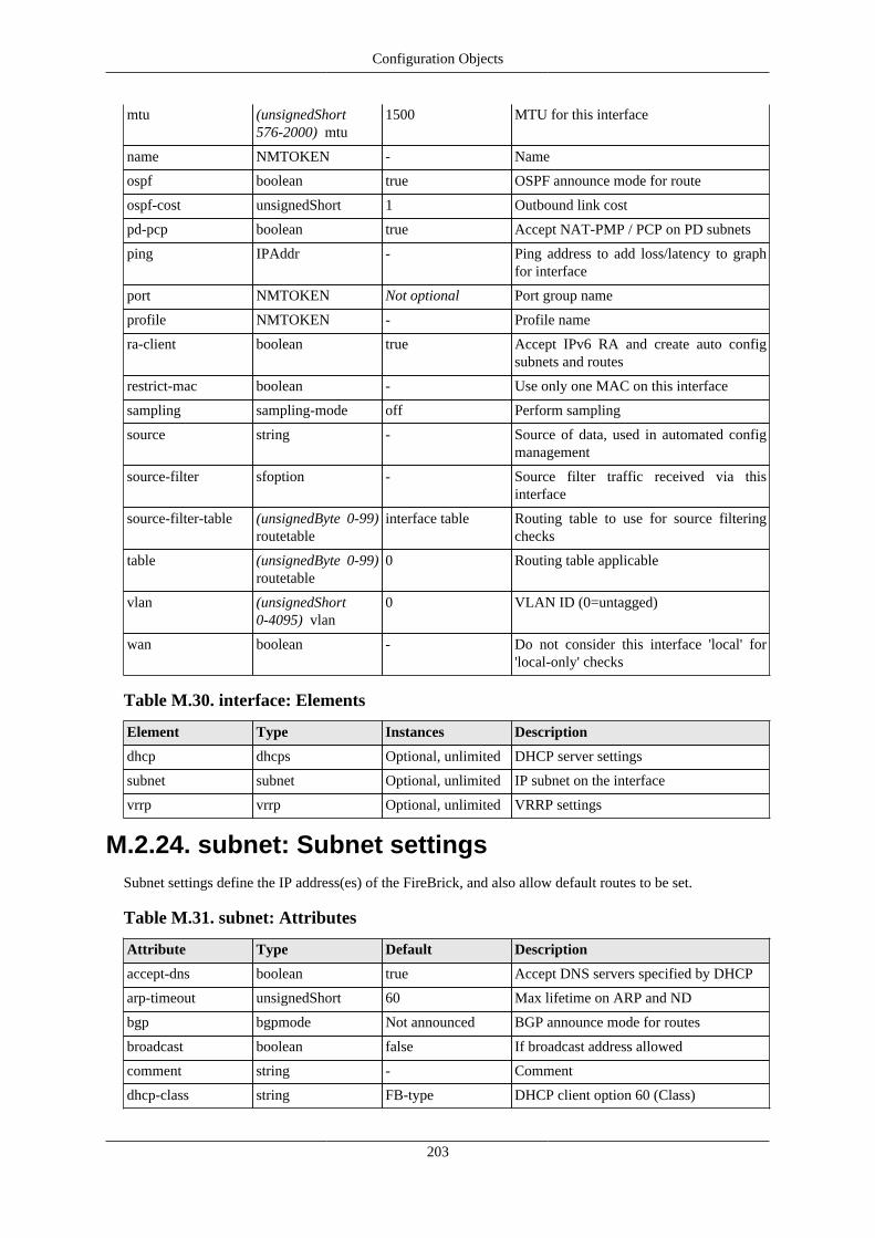
Configuration Objects
203
mtu (unsignedShort576-2000) mtu
1500 MTU for this interface
name NMTOKEN - Name
ospf boolean true OSPF announce mode for route
ospf-cost unsignedShort 1 Outbound link cost
pd-pcp boolean true Accept NAT-PMP / PCP on PD subnets
ping IPAddr - Ping address to add loss/latency to graphfor interface
port NMTOKEN Not optional Port group name
profile NMTOKEN - Profile name
ra-client boolean true Accept IPv6 RA and create auto configsubnets and routes
restrict-mac boolean - Use only one MAC on this interface
sampling sampling-mode off Perform sampling
source string - Source of data, used in automated configmanagement
source-filter sfoption - Source filter traffic received via thisinterface
source-filter-table (unsignedByte 0-99)routetable
interface table Routing table to use for source filteringchecks
table (unsignedByte 0-99)routetable
0 Routing table applicable
vlan (unsignedShort0-4095) vlan
0 VLAN ID (0=untagged)
wan boolean - Do not consider this interface 'local' for'local-only' checks
Table M.30. interface: Elements
Element Type Instances Description
dhcp dhcps Optional, unlimited DHCP server settings
subnet subnet Optional, unlimited IP subnet on the interface
vrrp vrrp Optional, unlimited VRRP settings
M.2.24. subnet: Subnet settingsSubnet settings define the IP address(es) of the FireBrick, and also allow default routes to be set.
Table M.31. subnet: Attributes
Attribute Type Default Description
accept-dns boolean true Accept DNS servers specified by DHCP
arp-timeout unsignedShort 60 Max lifetime on ARP and ND
bgp bgpmode Not announced BGP announce mode for routes
broadcast boolean false If broadcast address allowed
comment string - Comment
dhcp-class string FB-type DHCP client option 60 (Class)

Configuration Objects
204
dhcp-client-id string MAC DHCP client option 61 (Client-Identifier)
gateway List of IPAddr - One or more gateways to install
ip List of IPSubnet Automatic by DHCP One or more IP/len
localpref unsignedInt 4294967295 Localpref for subnet (highest wins)
mtu (unsignedShort576-2000) mtu
As interface MTU for subnet
name string - Name
nat boolean false Short cut to set nat default mode on all IPv4traffic from subnet (can be overridden byfirewall rules)
ospf boolean true OSPF announce mode for route
pcp boolean If nat Accept NAT-PMP / PCP
profile NMTOKEN - Profile name
proxy-arp boolean false Answer ARP/ND by proxy if we haverouting
ra ramode false If to announce IPv6 RA for this subnet
ra-dns List of IP6Addr - List of recursive DNS servers in routeannouncements
ra-managed dhcpv6control - RA 'M' (managed) flag
ra-max (unsignedShort4-1800) ra-max
600 Max RA send interval
ra-min (unsignedShort3-1350) ra-min
- Min RA send interval
ra-mtu unsignedShort As subnet MTU to use on RA
ra-other dhcpv6control - RA 'O' (other) flag
ra-profile NMTOKEN - Profile, if inactive then forces low priorityRA
source string - Source of data, used in automated configmanagement
test IPAddr - Test link state using ARP/ND for this IP
ttl unsignedByte 64 TTL for originating traffic via subnet
M.2.25. vrrp: VRRP settings
VRRP settings provide virtual router redundancy for the FireBrick. Profile inactive does not disable vrrp butforces vrrp low priority. Use different VRID on different VLANs.
Table M.32. vrrp: Attributes
Attribute Type Default Description
answer-ping boolean true Whether to answer PING to VRRP IPswhen master
comment string - Comment
delay unsignedInt 60 Delay after routing established beforepriority returns to normal
interval unsignedShort 100 Transit interval (centiseconds)

Configuration Objects
205
ip List of IPAddr Not optional One or more IP addresses to announce
log NMTOKEN Not logging Log events
log-error NMTOKEN log as event Log errors
low-priority unsignedByte 1 Lower priority applicable until routingestablished
name NMTOKEN - Name
preempt boolean true Whether pre-empt allowed
priority unsignedByte 100 Normal priority
profile NMTOKEN - Profile name
source string - Source of data, used in automated configmanagement
test List of IPAddr - List of IPs to which routing must exist elselow priority (deprecated)
use-vmac boolean true Whether to use the special VMAC or usenormal MAC
version3 boolean v2 for IPv4, v3 forIPv6
Use only version 3
vrid unsignedByte 42 VRID
M.2.26. dhcps: DHCP server settingsSettings for DHCP server
Table M.33. dhcps: Attributes
Attribute Type Default Description
boot IP4Addr - Next/boot server
boot-file string - Boot filename
class string - Vendor class match
client-name string - Client name match
comment string - Comment
dns List of IP4Addr Our IP DNS resolvers
domain string From system settings DNS domain
domain-search string - DNS domain search list (list will betruncated to fit one attribute)
force boolean - Send all options even if not requested
gateway IP4Subnet Our IP Gateway
ip List of IP4Range 0.0.0.0/0 Address pool
lease duration 2:00:00 Lease length
log NMTOKEN Not logging Log events (allocations)
mac List up to12 (hexBinary)macprefix
- Partial or full MAC addresses
name string - Name
ntp List of IP4Addr From system settings NTP server
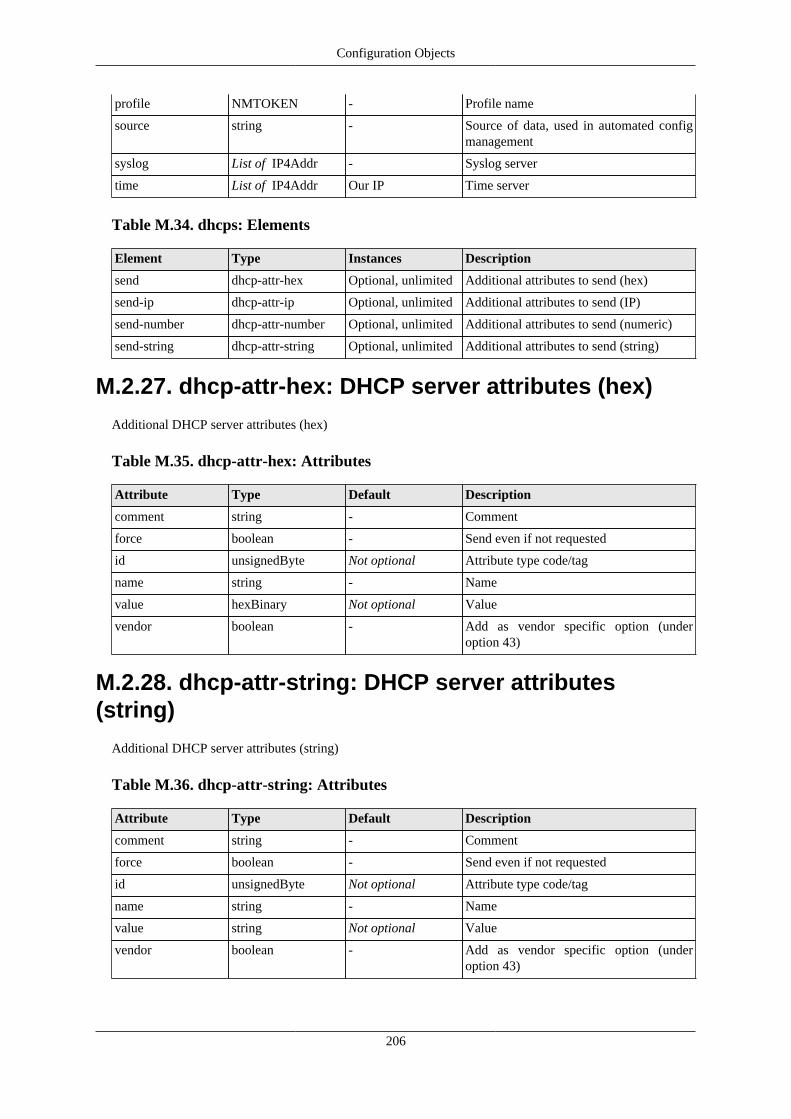
Configuration Objects
206
profile NMTOKEN - Profile name
source string - Source of data, used in automated configmanagement
syslog List of IP4Addr - Syslog server
time List of IP4Addr Our IP Time server
Table M.34. dhcps: Elements
Element Type Instances Description
send dhcp-attr-hex Optional, unlimited Additional attributes to send (hex)
send-ip dhcp-attr-ip Optional, unlimited Additional attributes to send (IP)
send-number dhcp-attr-number Optional, unlimited Additional attributes to send (numeric)
send-string dhcp-attr-string Optional, unlimited Additional attributes to send (string)
M.2.27. dhcp-attr-hex: DHCP server attributes (hex)
Additional DHCP server attributes (hex)
Table M.35. dhcp-attr-hex: Attributes
Attribute Type Default Description
comment string - Comment
force boolean - Send even if not requested
id unsignedByte Not optional Attribute type code/tag
name string - Name
value hexBinary Not optional Value
vendor boolean - Add as vendor specific option (underoption 43)
M.2.28. dhcp-attr-string: DHCP server attributes(string)
Additional DHCP server attributes (string)
Table M.36. dhcp-attr-string: Attributes
Attribute Type Default Description
comment string - Comment
force boolean - Send even if not requested
id unsignedByte Not optional Attribute type code/tag
name string - Name
value string Not optional Value
vendor boolean - Add as vendor specific option (underoption 43)

Configuration Objects
207
M.2.29. dhcp-attr-number: DHCP server attributes(numeric)
Additional DHCP server attributes (numeric)
Table M.37. dhcp-attr-number: Attributes
Attribute Type Default Description
comment string - Comment
force boolean - Send even if not requested
id unsignedByte Not optional Attribute type code/tag
name string - Name
value unsignedInt Not optional Value
vendor boolean - Add as vendor specific option (underoption 43)
M.2.30. dhcp-attr-ip: DHCP server attributes (IP)Additional DHCP server attributes (IP)
Table M.38. dhcp-attr-ip: Attributes
Attribute Type Default Description
comment string - Comment
force boolean - Send even if not requested
id unsignedByte Not optional Attribute type code/tag
name string - Name
value IP4Addr Not optional Value
vendor boolean - Add as vendor specific option (underoption 43)
M.2.31. pppoe: PPPoE settingsPPPoE endpoint settings
Table M.39. pppoe: Attributes
Attribute Type Default Description
ac-name string Any a/c name asclient, else same as'name'
Access concentrator name
accept-dns boolean true Accept DNS servers specified by far end
bgp bgpmode Not announced BGP announce mode for routes
calling-prefix string - Prefix on calling number (BRAS mode)
comment string - Comment
cug (unsignedShort1-32767) cug
- Closed user group ID
cug-restrict boolean - Closed user group restricted traffic (only to/from same CUG ID)

Configuration Objects
208
fast-retry boolean - Aggressive re-connect
graph (token) graphname - Graph name
ip-over-lcp boolean auto Sends all IP packets as LCP
lcp-rate unsignedByte 10 LCP interval (seconds)
lcp-timeout unsignedByte 61 LCP timeout (seconds)
local IP4Addr - Local IPv4 address
localpref unsignedInt 4294967295 Localpref for route (highest wins)
log NMTOKEN Not logging Log events
log-debug NMTOKEN Not logging Log debug
log-error NMTOKEN Not logging Log as events
mode pppoe-mode client PPPoE server/client mode
mtu (unsignedShort576-2000) mtu
1492 MTU for link
name NMTOKEN - Name
nat boolean false NAT IPv4 traffic to this link unlessotherwise set by rules
ospf boolean true OSPF announce mode for route
password Secret - User password
pd-interface List of NMTOKEN Auto Interfaces for IPv6 prefix delegation
port NMTOKEN - Port group name
profile NMTOKEN - Profile name
remote IP4Addr - Remote IPv4 address
rfc4638 boolean If over 1492 MTU Send RFC4638 PPP-Max-Payload
routes List of IPPrefix Default gateway Routes when link up
service string Any service Service name
source string - Source of data, used in automated configmanagement
speed unsignedInt - Default egress rate limit (b/s)
table (unsignedByte 0-99)routetable
- Routing table number for payload
tcp-mss-fix boolean true Adjust MSS option in TCP SYN to fixsession MSS
username string - User name
vlan (unsignedShort0-4095) vlan
0 VLAN ID (0=untagged)
Table M.40. pppoe: Elements
Element Type Instances Description
route ppp-route Optional, unlimited Routes to apply when ppp link is up
M.2.32. ppp-route: PPP routes
Routes that apply when link is up

Configuration Objects
209
Table M.41. ppp-route: Attributes
Attribute Type Default Description
bgp bgpmode Not announced BGP announce mode for routes
comment string - Comment
ip List of IPPrefix Not optional One or more network prefixes
localpref unsignedInt 4294967295 Localpref of network (highest wins)
name string - Name
ospf boolean true OSPF announce mode for route
profile NMTOKEN - Profile name
source string - Source of data, used in automated configmanagement
M.2.33. usb: USB 3G/dongle settingsUSB config settings including 3G data
Table M.42. usb: Attributes
Attribute Type Default Description
log NMTOKEN Web/console Log events
log-debug NMTOKEN Not logged Log errors
log-error NMTOKEN Web/Flash/console Log errors
profile NMTOKEN - Profile name
Table M.43. usb: Elements
Element Type Instances Description
dongle dongle Optional, up to 10 USB 3G/dongle settings
M.2.34. dongle: 3G/dongle settings3G/dongle config settings
Table M.44. dongle: Attributes
Attribute Type Default Description
accept-dns boolean true Accept DNS servers specified by far end
apn string From SIM Mobile access point name
bgp bgpmode Not announced BGP announce mode for routes
comment string - Comment
context pdp-context-type ip Type of connection to make
cug (unsignedShort1-32767) cug
- Closed user group ID
cug-restrict boolean - Closed user group restricted traffic (only to/from same CUG ID)
dial-string string ATV1 ATE0 AT+CFUN=1AT&D2&C1S0=0S7=60
Space separated AT command stringswhich can include [apn] and [context]

Configuration Objects
210
AT+CGDCONT=1,"[context]","[apn]"ATDT*99#
graph (token) graphname - Graph name
local IP4Addr - Local IPv4 address
localpref unsignedInt 4294967295 Localpref for route (highest wins)
log NMTOKEN Log as specified inparent usb config
Log events
log-debug NMTOKEN Log as specified inparent usb config
Log debug
log-error NMTOKEN Log as specified inparent usb config
Log errors
modeswitch string standard switching Mode switch mechanism
mtu (unsignedShort576-2000) mtu
1500 MTU for link
name NMTOKEN - Name
nat boolean true NAT IPv4 traffic to this link unlessotherwise set in rules
ospf boolean true OSPF announce mode for route
password Secret - User password
product hexBinary - Product ID - used to match a configurationwith specific device vendor
profile NMTOKEN - Profile name
remote IP4Addr - Remote IPv4 address
routes List of IPPrefix Default gateway Routes when link up
socket string - What USB socket ID should this configapply to
source string - Source of data, used in automated configmanagement
speed unsignedInt - Default egress rate limit (b/s)
table (unsignedByte 0-99)routetable
From interface Routing table number for payload
tcp-mss-fix boolean true Adjust MSS option in TCP SYN to fixsession MSS
username string - User name
vendor hexBinary - Vendor ID - used to match a configurationwith specific device vendor
Table M.45. dongle: Elements
Element Type Instances Description
route ppp-route Optional, unlimited Routes to apply when link is up
M.2.35. route: Static routesStatic routes define prefixes which are permanently in the routing table, and whether these should be announcedby routing protocols or not.

Configuration Objects
211
Table M.46. route: Attributes
Attribute Type Default Description
bgp bgpmode Not announced BGP announce mode for routes
comment string - Comment
gateway List of IPAddr Not optional One or more target gateway IPs
graph (token) graphname - Graph name
ip List of IPPrefix Not optional One or more network prefixes
localpref unsignedInt 4294967295 Localpref of network (highest wins)
name string - Name
ospf boolean true OSPF announce mode for route
profile NMTOKEN - Profile name
source string - Source of data, used in automated configmanagement
speed unsignedInt - Egress rate limit (b/s)
table (unsignedByte 0-99)routetable
0 Routing table number
M.2.36. network: Locally originated networksNetwork blocks that are announced but not actually added to internal routes - note that blackhole and nowhereobjects can also announce but add routing.
Table M.47. network: Attributes
Attribute Type Default Description
as-path List up to 10unsignedInt
- Custom AS path as if network received
bgp bgpmode true BGP announce mode for routes
comment string - Comment
ip List of IPPrefix Not optional One or more network prefixes
localpref unsignedInt 4294967295 Localpref of network (highest wins)
name string - Name
ospf boolean true OSPF announce mode for route
profile NMTOKEN - Profile name
source string - Source of data, used in automated configmanagement
table (unsignedByte 0-99)routetable
0 Routing table number
tag List of Community - List of community tags
M.2.37. blackhole: Dead end networksNetworks that go nowhere
Table M.48. blackhole: Attributes
Attribute Type Default Description

Configuration Objects
212
as-path List up to 10unsignedInt
- Custom AS path as if network received
bgp bgpmode false BGP announce mode for routes
comment string - Comment
ip List of IPPrefix Not optional One or more network prefixes
localpref unsignedInt 4294967295 Localpref of network (highest wins)
name string - Name
no-fib boolean - Route not in forwarding, only for EBGP
ospf boolean - OSPF announce mode for route
profile NMTOKEN - Profile name
source string - Source of data, used in automated configmanagement
table (unsignedByte 0-99)routetable
0 Routing table number
tag List of Community - List of community tags
M.2.38. loopback: Locally originated networks
Loopback addresses define local IP addresses
Table M.49. loopback: Attributes
Attribute Type Default Description
as-path List up to 10unsignedInt
- Custom AS path as if network received
bgp bgpmode Not announced BGP announce mode for routes
comment string - Comment
ip List of IPAddr Not optional One or more local network addresses
localpref unsignedInt 4294967295 Localpref of network (highest wins)
name string - Name
ospf boolean true OSPF announce mode for route
profile NMTOKEN - Profile name
source string - Source of data, used in automated configmanagement
table (unsignedByte 0-99)routetable
0 Routing table number
tag List of Community - List of community tags
M.2.39. ospf: Overall OSPF settings
The OSPF element defines general OSPF settings. Where interfaces/table specified, first matching OSPF configis applied. Only provides OSPF internal and AS-border router functionality.
Table M.50. ospf: Attributes
Attribute Type Default Description

Configuration Objects
213
area-id IP4Addr 0.0.0.0 Area ID
auth-algorithm ipsec-auth-algorithm AES-XCBC Authentication algorithm for OSPFv3
auth-key hexBinary - Key for OSPFv3 authentication
bgp bgpmode - BGP announce mode for routes
comment string - Comment
crypt-algorithm ipsec-crypt-algorithm
null Encryption algorithm for OSPFv3
crypt-key hexBinary - Key for OSPFv3 encryption
dead-interval duration 45 Default router dead interval
hello-interval duration 9 Default hello interval
instance unsignedByte - Instance ID for OSPFv3
interfaces List of NMTOKEN All Ethernet interfaces to which this OSPFconfig applies
ipsec-type ipsec-type ESP Encapsulation type for OSPFv3 security
key-id integer 1 Key ID for OSPFv2 MD5 authentication(-1 for simple auth)
localpref unsignedInt - Base localpref (highest wins)
log NMTOKEN Not logging Log calls
log-debug NMTOKEN Not logging Log debug and SIP messages
log-error NMTOKEN Log as event Log errors
name string - Name
password Secret - Secret for OSPFv2 MD5 authentication
priority unsignedByte 1 Default priority
profile NMTOKEN - Profile name
router-id IP4Addr - Router ID
rxmt-interval duration 3 Default router retransmit interval
source string - Source of data, used in automated configmanagement
spi (unsignedInt256-4294967295)ipsec-spi
- SPI for OSPFv3 security (unset for nosecurity)
stub boolean - Stub area
table (unsignedByte 0-99)routetable
0 Routing table
M.2.40. namedbgpmap: Mapping and filtering rules ofBGP prefixes
This defines a set of named rules for mapping and filtering of prefixes to/from a BGP peer.
Table M.51. namedbgpmap: Attributes
Attribute Type Default Description
comment string - Comment
name NMTOKEN Not optional Name

Configuration Objects
214
source string - Source of data, used in automated configmanagement
Table M.52. namedbgpmap: Elements
Element Type Instances Description
match bgprule Optional, unlimited List rules, in order of checking
M.2.41. bgprule: Individual mapping/filtering ruleAn individual rule for BGP mapping/filtering
Table M.53. bgprule: Attributes
Attribute Type Default Description
comment string - Comment
community Community - Community that must be present to match
detag List of Community - List of community tags to remove
drop boolean - Do not import/export this prefix
localpref unsignedInt - Set localpref (highest wins)
med unsignedInt - Set MED
name string - Name
no-community Community - Community that must not be present tomatch
pad unsignedByte - Pad (prefix stuff) our AS on export by thismany, can be zero to not send our AS
prefix List of IPFilter - Prefixes that this rule applies to
source string - Source of data, used in automated configmanagement
tag List of Community - List of community tags to add
M.2.42. bgp: Overall BGP settingsThe BGP element defines general BGP settings and a list of peer definitions for the individual BGP peers.
Table M.54. bgp: Attributes
Attribute Type Default Description
as unsignedInt - Our AS
blackhole-community
Community - Community tag to mark black hole routes
cluster-id IP4Addr - Our cluster ID
comment string - Comment
dead-end-community
Community - Community tag to mark dead end routes
greyhole-community
Community - Community tag to mark black hole routeswith no-fib
id IP4Addr - Our router ID
log NMTOKEN Not logging Log events

Configuration Objects
215
name string - Name
source string - Source of data, used in automated configmanagement
table (unsignedByte 0-99)routetable
0 Routing table number
Table M.55. bgp: Elements
Element Type Instances Description
peer bgppeer Optional, up to 50 List of peers/neighbours
M.2.43. bgppeer: BGP peer definitionsThe peer definition specifies the attributes of an individual peer. Multiple IP addresses can be specified,typically for IPv4 and IPv6 addresses for the same peer, but this can be used for a group of similar peers.
Table M.56. bgppeer: Attributes
Attribute Type Default Description
add-own-as boolean - Add our AS on exported routes
allow-export boolean true for customer Ignore no-export community and exportanyway
allow-only-their-as boolean - Only accept routes that are solely the peersAS
allow-own-as boolean - Allow our AS inbound
as unsignedInt - Peer AS
blackhole-community
Community Not announcedon EBGP, ourblackhole-community if IBGP
Egress community tag to mark black holeroutes
capability-as4 boolean true If supporting AS4
capability-graceful-restart
boolean true If supporting Graceful Restart
capability-mpe-ipv4 boolean true If supporting MPE for IPv4
capability-mpe-ipv6 boolean true If supporting MPE for IPv6
capability-route-refresh
boolean true If supporting Route Refresh
clean-shutdown-wait
duration - Send peers low priority and delay onshutdown
comment string - Comment
drop-default boolean false Ignore default route received
export-filters List of NMTOKEN - Named export filters to apply
export-med unsignedInt - Set MED on exported routes (unless exportfilter sets it)
holdtime unsignedInt 30 Hold time
ignore-bad-optional-partial
boolean true Ignore routes with a recognised badlyformed optional that is flagged partial
import-filters List of NMTOKEN - Named import filters to apply

Configuration Objects
216
import-localpref unsignedInt - Set localpref on imported routes (unlessimport filter sets it)
import-tag List of Community - List of community tags to add in additionto any import filters
in-soft boolean - Mark received routes as soft
ip List of IPAddr - One or more IPs of neighbours (omit toallow incoming)
log-debug NMTOKEN Not logging Log debug
max-prefix (unsignedInt1-10000) bgp-prefix-limit
10000 Limit prefixes (IPv4+IPv6)
md5 Secret - MD5 signing secret
name string - Name
next-hop-self boolean false Force us as next hop outbound
no-fib boolean - Don't include received routes in packetforwarding
pad unsignedByte - Pad (prefix stuff) our AS on export by thismany
profile NMTOKEN - Profile name
reduce-recursion boolean false Override incoming next hop if not localsubnet
same-ip-type boolean true Only accept/send IPv4 routes to IPv4 peersand IPv6 routes to IPv6 peers
send-default boolean false Send a default route to this peer
send-no-routes boolean false Don't send any normal routes
shutdown boolean - Shutdown this neighbour (deprecated, useprofile)
source string - Source of data, used in automated configmanagement
timer-idle unsignedInt 60 Idle time after error
timer-openwait unsignedInt 10 Time to wait for OPEN on connection
timer-retry unsignedInt 10 Time to retry the neighbour
ttl-security byte - Enable RFC5082 TTL security (if +ve, 1to 127), i.e. 1 for adjacent router. If -ve (-1to -128) set forced sending TTL, i.e. -1 forTTL of 1 sending, and not checking.
type peertype normal Type of neighbour (affects some defaults)
use-vrrp-as-self boolean true if customer/transit type
Use VRRP address as self if possible
Table M.57. bgppeer: Elements
Element Type Instances Description
export bgpmap Optional Mapping and filtering rules of announcingprefixes to peer
import bgpmap Optional Mapping and filtering rules of acceptingprefixes from peer

Configuration Objects
217
M.2.44. bgpmap: Mapping and filtering rules of BGPprefixes
This defines the rules for mapping and filtering of prefixes to/from a BGP peer.
Table M.58. bgpmap: Attributes
Attribute Type Default Description
comment string - Comment
detag List of Community - List of community tags to remove
drop boolean - Do not import/export this prefix
localpref unsignedInt - Set localpref (highest wins)
med unsignedInt - Set MED
prefix List of IPFilter - Drop all that are not in this prefix list
source string - Source of data, used in automated configmanagement
tag List of Community - List of community tags to add
Table M.59. bgpmap: Elements
Element Type Instances Description
match bgprule Optional, unlimited List rules, in order of checking
M.2.45. cqm: Constant Quality Monitoring settingsConstant quality monitoring (graphs and data) have a number of settings. Most of the graphing settings can beoverridden when a graph is collected so these define the defaults in many cases.
Table M.60. cqm: Attributes
Attribute Type Default Description
ave Colour #08f Colour for average latency
axis Colour black Axis colour
background Colour white Background colour
bottom unsignedByte 11 Pixels space at bottom of graph
dateformat string %Y-%m-%d Date format
dayformat string %a Day format
fail Colour red Colour for failed (dropped) seconds
fail-level unsignedInt 1 Fail level not expected on low usage
fail-level1 unsignedByte 3 Loss level 1
fail-level2 unsignedByte 50 Loss level 2
fail-score unsignedByte 200 Score for fail and low usage
fail-score1 unsignedByte 100 Score for on/above level 1
fail-score2 unsignedByte 200 Score for on/above level 2
fail-usage unsignedInt 128000 Usage below which fail is not expected
fblogo Colour #bd1220 Colour for logo
graticule Colour grey Graticule colour

Configuration Objects
218
heading string - Heading of graph
hourformat string %H Hour format
key unsignedByte 90 Pixels space for key
label-ave string Ave Label for average latency
label-damp string Damp% Label for % shaper damping
label-fail string %Fail Label for seconds (%) failed
label-latency string Latency Label for latency
label-max string Max Label for maximum latency
label-min string Min Label for minimum latency
label-off string Off Label for off line seconds
label-period string Period Label for period
label-poll string Polls Label for polls
label-rej string %Reject Label for rejected seconds
label-rx string Rx Label for Rx traffic level
label-score string Score Label for score
label-sent string Sent Label for seconds polled
label-shaper string Shaper Label for shaper
label-time string Time Label for time
label-traffic string Traffic (bit/s) Label for traffic level
label-tx string Tx Label for Tx traffic level
latency-level unsignedInt 100000000 Latency level not expected on low usage
latency-level1 unsignedInt 100000000 Latency level 1 (ns)
latency-level2 unsignedInt 500000000 Latency level 2 (ns)
latency-score unsignedByte 200 Score for high latency and low usage
latency-score1 unsignedByte 10 Score for on/above level 1
latency-score2 unsignedByte 20 Score for on/above level 2
latency-usage unsignedInt 128000 Usage below which latency is not expected
left unsignedByte 0 Pixels space left of main graph
log NMTOKEN Not logging Log events
marker-width string - Marker + on tx/rx
max Colour green Colour for maximum latency
min Colour #008 Colour for minimum latency
ms-max positiveInteger 500 ms max height
off Colour #c8f Colour for off line seconds
outside Colour transparent Colour for outer border
ping-update duration 1:00:00 Interval for periodic updates
ping-url string - URL for ping list
rej Colour #f8c Colour for off line seconds
right unsignedByte 50 Pixels space right of main graph
rx Colour #800 Colour for Rx traffic level
secret Secret - Secret for MD5 coded URLs

Configuration Objects
219
sent Colour #ff8 Colour for polled seconds
share-interface NMTOKEN - Interface on which to broadcast data forshaper sharing
share-secret string - Secret to validate shaper sharing
stroke-width string - Stroke line tx/rx
subheading string - Subheading of graph
svg-css string - URL for SVG CSS instead of local stylesettings
svg-title boolean - Include mouseover title text on svg
text Colour black Colour for text
text1 string - Text line 1
text2 string - Text line 2
text3 string - Text line 3
text4 string - Text line 4
timeformat string %Y-%m-%d %H:%M:%S
Time format
top unsignedByte 4 Pixels space at top of graph
tx Colour #080 Colour for Tx traffic level
M.2.46. l2tp: L2TP settingsL2TP settings for incoming and outgoing L2TP connections
Table M.61. l2tp: Attributes
Attribute Type Default Description
accounting-interval duration 1:00:00 Periodic interim accounting interval
send-acct-delay boolean - Send Acct-Delay as well as Event-Timestamp on accounting
Table M.62. l2tp: Elements
Element Type Instances Description
incoming l2tp-incoming Optional, unlimited Incoming L2TP connections
outgoing l2tp-outgoing Optional, unlimited Outgoing L2TP connections
M.2.47. l2tp-outgoing: L2TP settings for outgoing L2TPconnections
L2TP tunnel settings for outgoing L2TP connections
Table M.63. l2tp-outgoing: Attributes
Attribute Type Default Description
accept-dns boolean true Accept DNS servers specified by far end
bgp bgpmode Not announced BGP announce mode for routes
called string - called-station-idi to send
calling string - calling-station-id to send

Configuration Objects
220
comment string - Comment
cug (unsignedShort1-32767) cug
- Closed user group ID
cug-restrict boolean - Closed user group restricted traffic (only to/from same CUG ID)
fail-lockout unsignedByte 1 Interval kept in failed state
graph string - Graph name
hdlc boolean true Send HDLC header (FF03) on all PPPframes
hello-interval unsignedByte 10 Interval between HELLO messages
hostname string System name The hostname we quote on tunnel connect
lcp-data-len unsignedByte - LCP echo data field length
lcp-rate unsignedByte 10 LCP interval (seconds)
lcp-timeout unsignedByte 61 LCP timeout (seconds)
local IP4Addr - Local IPv4 address
local-ip IPAddr - IP of our end
localpref unsignedInt 4294967295 Localpref for remote-ip/routes (highestwins)
log NMTOKEN Not logging Log events
log-debug NMTOKEN Not logging Log debug
log-error NMTOKEN Log as event Log errors
min-retry duration 10 Minimum session time before retryingconnection
mtu (unsignedShort576-2000) mtu
- Default MTU for sessions in this tunnel
name NMTOKEN - Name
nat boolean true NAT IPv4 traffic to this link unlessotherwise set in rules
open-timeout unsignedByte 10 Interval before OPEN considered failed
ospf boolean true OSPF announce mode for route
password Secret - Password for login
payload-table (unsignedByte 0-99)routetable
0 Routing table number for payload traffic
profile NMTOKEN - Profile name
receive-window unsignedShort Not sent Receive window to advise on connection
remote IP4Addr - Remote IPv4 address
retry-timeout unsignedByte 10 Interval to retry sending control messagesbefore fail
routes List of IPPrefix Default gateway Routes when link up
rx-speed unsignedInt - Send ingress rate (b/s)
secret Secret - Shared secret
server IPNameAddr Not optional IP/name of far end
source string - Source of data, used in automated configmanagement

Configuration Objects
221
table (unsignedByte 0-99)routetable
0 Routing table number for L2TP session
tcp-mss-fix boolean false Adjust MSS option in TCP SYN to fixsession MSS
tx-speed unsignedInt - Egress rate limit (b/s)
username string - User name for login
Table M.64. l2tp-outgoing: Elements
Element Type Instances Description
route ppp-route Optional, unlimited Routes to apply when link is up
M.2.48. l2tp-incoming: L2TP settings for incomingL2TP connections
L2TP tunnel settings for incoming L2TP connections
Table M.65. l2tp-incoming: Attributes
Attribute Type Default Description
allow List ofIPNameRange
- List of IP ranges from which connects canbe made
bgp bgpmode Not announced BGP announce mode for routes
comment string - Comment
damping boolean false Apply damping to sessions if limiting onshaper
dhcpv6dns List of IP6Addr - List of IPv6 DNS servers
dos-limit unsignedInt 10000 Per second per session tx packet drop limitfor DOS protection
fail-lockout unsignedByte 60 Interval kept in failed state
graph string - Graph name
hdlc boolean true Send HDLC header (FF03) on all PPPframes
hello-interval unsignedByte 60 Interval between HELLO messages
icmp-ppp boolean false Use PPP endpoint for ICMP
ipv6ep IP4Addr - Local end IPv4 for IPv6 tunnels
lcp-data-len unsignedByte - LCP data field length
lcp-mru-fix boolean false Restart LCP if RAS negotiated MRU is toohigh
lcp-rate unsignedByte 1 LCP interval (seconds)
lcp-timeout unsignedByte 10 LCP timeout (seconds)
local-hostname string System name Hostname quoted on reply
log NMTOKEN Not logging Log events
log-debug NMTOKEN Not logging Log debug
log-error NMTOKEN Log as event Log errors

Configuration Objects
222
mtu (unsignedShort576-2000) mtu
- Default MTU for sessions in this tunnel
name string - Name
open-timeout unsignedByte 60 Interval before OPEN considered failed
ospf boolean true OSPF announce mode for route
payload-table (unsignedByte 0-99)routetable
0 Routing table number for payload traffic
pppdns1 IP4Addr - PPP DNS1 IPv4 default
pppdns2 IP4Addr - PPP DNS2 IPv4 default
pppip IP4Addr - Local end PPP IPv4
profile NMTOKEN - Profile name
radius string - Name for RADIUS server config to use
radius-nas-ip radius-nas lac Pass remote (LAC) or local (LNS) asRADIUS NAS IP / port
receive-window unsignedShort Not sent Receive window to advise on connection
remote-hostname string - Hostname expected on connection
require-platform boolean false All sessions require a platform RADIUSfirst
require-radius-acct boolean - Close session if cannot do RADIUSaccounting
retry-timeout unsignedByte 60 Interval to retry sending control messagesbefore fail
secret Secret - Shared secret (for far end to check)
shutdown boolean false Refuse all new sessions or tunnels
source string - Source of data, used in automated configmanagement
source-ip IPAddr - IP of our end for relayed (on same table)
speed unsignedInt - Default egress rate limit (b/s)
table (unsignedByte 0-99)routetable
Any Routing table number for L2TP session
tcp-mss-fix boolean false Adjust MSS option in TCP SYN to fixsession MSS
test List of IPAddr - List of IPs to which routing must exist elsetunnel dropped (deprecated)
Table M.66. l2tp-incoming: Elements
Element Type Instances Description
match l2tp-relay Optional, unlimited Rules for relaying connections and localauthentication
M.2.49. l2tp-relay: Relay and local authentication rulesfor L2TP
Rules for relaying L2TP or local authentication

Configuration Objects
223
Table M.67. l2tp-relay: Attributes
Attribute Type Default Description
called-station-id List of string - One or more patterns to match called-station-id
calling-station-id List of string - One or more patterns to match calling-station-id
comment string - Comment
graph (token) graphname - Graph name
ip-over-lcp boolean - Send IP over LCP (local auth)
lcp-echo-mim boolean - Handle LCP echos in the middle on relayedconnection
localpref unsignedInt 4294967295 Localpref for remote-ip/routes (highestwins)
name string - Name
password Secret - Password check
profile NMTOKEN - Profile name
relay-hostname string - Hostname for L2TP connection
relay-ip List of IPAddr - Target IP(s) for L2TP connection
relay-pick boolean - If set, try one of the relay IPs at random first
relay-secret Secret - Shared secret for L2TP connection
remote-ip IP4Addr - Remote end PPP IPv4 (local auth)
remote-netmask IP4Addr - Remote end PPP Netmask (local auth)
routes List of IPPrefix - Additional routes when link up (local auth)
source string - Source of data, used in automated configmanagement
test List of IPAddr - List of IPs that must have routing for thistarget to be valid (deprecated)
username List of string - One or more patterns to match username
M.2.50. fb105: FB105 tunnel definitionFB105 tunnel definition
Table M.68. fb105: Attributes
Attribute Type Default Description
bgp bgpmode Not announced BGP announce mode for routes
comment string - Comment
fast-udp boolean true Send UDP packets marked not to bereordered
graph (token) graphname - Graph name
internal-ip IP4Addr local-ip Internal IP for traffic originated and sentdown tunnel
ip IP4Addr dynamic tunnel Far end IP
keep-alive boolean true if ip set Constantly send keep alive packets

Configuration Objects
224
local-id unsignedByte Not optional Unique local end tunnel ID
local-ip IP4Addr - Force specific local end IP
localpref unsignedInt 4294967295 Localpref for route (highest wins)
log NMTOKEN Not logging Log events
log-error NMTOKEN Log as event Log errors
mtu unsignedShort 1500 MTU for wrapped packets
name NMTOKEN - Name
obfuscate (hexBinary) hex32 - Scramble (not encrypt) data
ospf boolean true OSPF announce mode for route
payload-table (unsignedByte 0-99)routetable
0 Routing table number for payload traffic
port unsignedShort 1 UDP port to use
profile NMTOKEN - Profile name
remote-id unsignedByte Not optional Unique remote end tunnel ID
reorder boolean false Reorder incoming tunnel packets
reorder-maxq (unsignedInt 1-100)fb105-reorder-maxq
32 Max queue length for out of order packets
reorder-timeout (unsignedInt10-5000) fb105-reorder-timeout
100 Max time to delay out of order packet (ms)
routes List of IPPrefix None Routes when link up
satellite boolean - Mark links that are high speed and latencyfor split latency bonding (experimental)
secret Secret Unsigned Shared secret for tunnel
set unsignedByte - Set ID for reorder ID tagging (create a setof tunnels together)
sign-all boolean false All packets must be signed, not justkeepalives
source string - Source of data, used in automated configmanagement
speed unsignedInt no shaping Egress rate limit used (b/s)
table (unsignedByte 0-99)routetable
0 Routing table number for tunnel wrappers
tcp-mss-fix boolean true Adjust MSS option in TCP SYN to fixsession MSS
Table M.69. fb105: Elements
Element Type Instances Description
route fb105-route Optional, unlimited Routes to apply to tunnel when up
M.2.51. fb105-route: FB105 routes
Routes for prefixes that are sent to the FB105 tunnel when up

Configuration Objects
225
Table M.70. fb105-route: Attributes
Attribute Type Default Description
bgp bgpmode Not announced BGP announce mode for routes
comment string - Comment
ip List of IPPrefix Not optional One or more network prefixes
localpref unsignedInt 4294967295 Localpref of network (highest wins)
name string - Name
ospf boolean true OSPF announce mode for route
profile NMTOKEN - Profile name
source string - Source of data, used in automated configmanagement
M.2.52. ipsec-ike: IPsec configuration (IKEv2)
IPsec IKE and manually-keyed connection details
Table M.71. ipsec-ike: Attributes
Attribute Type Default Description
allow List ofIPNameRange
Allow fromanywhere
List of IP ranges from which IKEconnections are allowed
force-NAT List ofIPNameRange
- List of IP ranges of peers requiring forcedNAT-T
log NMTOKEN Not logging Log events
log-debug NMTOKEN Not logging Log debug
log-error NMTOKEN Log as event Log errors
trusted List ofIPNameRange
- List of IP ranges given higher priority whenestablshing new connections
comment string - Comment
source string - Source of data, used in automated configmanagement
Table M.72. ipsec-ike: Elements
Element Type Instances Description
IKE-proposal ike-proposal Optional, unlimited Proposals for IKE security association
IPsec-proposal ipsec-proposal Optional, unlimited Proposals for IPsec AH/ESP securityassociation
connection (ipsec-connection-common) ike-connection
Optional, unlimited IKE connections
manually-keyed (ipsec-connection-common) ipsec-manual
Optional, unlimited IPsec manually-keyed connections (notrecommended)
roaming ike-roaming Optional, unlimited IKE roaming IP pools

Configuration Objects
226
M.2.53. ike-connection: connection configurationIPsec IKE connection settings
Table M.73. ike-connection: Attributes
Attribute Type Default Description
bgp bgpmode Not announced BGP announce mode for routes
comment string - Comment
graph (token) graphname - Graph name
internal-ipv4 IP4Addr local-ip Internal IPv4 for traffic originated on theFireBrick and sent down tunnel
internal-ipv6 IP6Addr local-ip Internal IPv6 for traffic originated on theFireBrick and sent down tunnel
local-ip IPAddr - Local IP
localpref unsignedInt 4294967295 Localpref for route (highest wins)
log NMTOKEN Not logging Log events
log-debug NMTOKEN Not logging Log debug
log-error NMTOKEN Log as event Log errors
mtu unsignedShort 1500 MTU for wrapped packets
name NMTOKEN - Name
ospf boolean true OSPF announce mode for route
payload-table (unsignedByte 0-99)routetable
0 Routing table number for payload traffic
peer-ips List ofIPNameRange
Accept fromanywhere
peer's IP or range
profile NMTOKEN - Profile name
routes List of IPPrefix - Routes when link up
source string - Source of data, used in automated configmanagement
speed unsignedInt no shaping Egress rate limit used (b/s)
table (unsignedByte 0-99)routetable
0 Routing table number for IKE traffic andtunnel wrappers
tcp-mss-fix boolean true Adjust MSS option in TCP SYN to fixsession MSS
type ipsec-type ESP Encapsulation type
auth-method ike-authmethod Not optional method for authenticating self to peer
blackhole boolean false Blackhole routed traffic when tunnel is notup
certlist List of NMTOKEN use any suitable Certificate(s) to be used to authenticate self
dead-peer-detect duration 30 check peer is alive at least this often - 0 toinhibit
ike-proposals List of NMTOKEN use built-in defaultproposals
IKE proposal list
ipsec-proposals List of NMTOKEN use built-in defaultproposals
IPsec proposal list

Configuration Objects
227
lifetime duration 1:00:00 max lifetime before renegotiation
local-ID string - Local IKE ID
local-ts List of IPRange Allow any Valid outgoing-source/incoming-destination IPs for tunnelled traffic
mode ike-mode Wait ike connection setup mode
peer-ID string - Peer IKE ID
peer-auth-method ike-authmethod Use auth-method method for authenticating peer
peer-certlist List of NMTOKEN accept any suitable Certificate trust anchor(s) acceptable forauthenticating peer
peer-secret Secret use secret shared secret used to authenticate peer
peer-ts List of IPRange Allow any Valid outgoing-destination/incoming-source IPs for tunnelled traffic
peer-ts-from-routes boolean false Send traffic selector based on routing
query-eap-id boolean true Query client for EAP identity
roaming-pool NMTOKEN - IKE roaming IP pool
secret Secret - shared secret used to authenticate self topeer
Table M.74. ike-connection: Elements
Element Type Instances Description
route ipsec-route Optional, unlimited Routes to apply to tunnel when up
M.2.54. ipsec-route: IPsec tunnel routesRoutes for prefixes that are sent to the IPsec tunnel
Table M.75. ipsec-route: Attributes
Attribute Type Default Description
bgp bgpmode Not announced BGP announce mode for routes
comment string - Comment
ip List of IPPrefix Not optional One or more network prefixes
localpref unsignedInt 4294967295 Localpref of network (highest wins)
name string - Name
ospf boolean true OSPF announce mode for route
profile NMTOKEN - Profile name
source string - Source of data, used in automated configmanagement
M.2.55. ike-roaming: IKE roaming IP poolsPool of IP addresses and associated DNS/NBNS servers for dynamic IP allocation
Table M.76. ike-roaming: Attributes
Attribute Type Default Description

Configuration Objects
228
DNS List of IPAddr - List of DNS servers available to clients
NBNS List of IPAddr - List of NetBios name servers available toclients
comment string - Comment
ip List of IPRange Not optional List of IP ranges for allocation to road-warrior clients
name NMTOKEN Not optional Name
nat boolean false NAT incoming IPv4 traffic unless setotherwise in rules
source string - Source of data, used in automated configmanagement
M.2.56. ike-proposal: IKE security proposalProposal for establishing the IKE security association
Table M.77. ike-proposal: Attributes
Attribute Type Default Description
DHset Set of ike-DH Accept anysupported group
Diffie-Hellman group for IKE negotiation
PRFset Set of ike-PRF Accept anysupported function
Pseudo-Random function for keygeneration
authset Set of ipsec-auth-algorithm
Accept anysupported algorithm
Integrity check algorithm for IKE messages
cryptset Set of ipsec-crypt-algorithm
Accept anysupported algorithm
Encryption algorithm for IKE messages
name NMTOKEN Not optional Name
M.2.57. ipsec-proposal: IPsec AH/ESP proposalProposal for establishing the IPsec AH/ESP keying information
Table M.78. ipsec-proposal: Attributes
Attribute Type Default Description
DHset Set of ike-DH Accept anysupported group
Diffie-Hellman group for IPsec keynegotiation
ESN Set of ike-ESN Accept ESN or shortSN
Support for extended sequence numbers
authset Set of ipsec-auth-algorithm
Accept anysupported algorithm
Integrity check algorithm for IPsec traffic
cryptset Set of ipsec-crypt-algorithm
Accept anysupported algorithm
Encryption algorithm for IPsec traffic
name NMTOKEN Not optional Name
M.2.58. ipsec-manual: peer configurationIPsec manually keyed connection settings (not recommended, use IKEv2 and secrets instead)
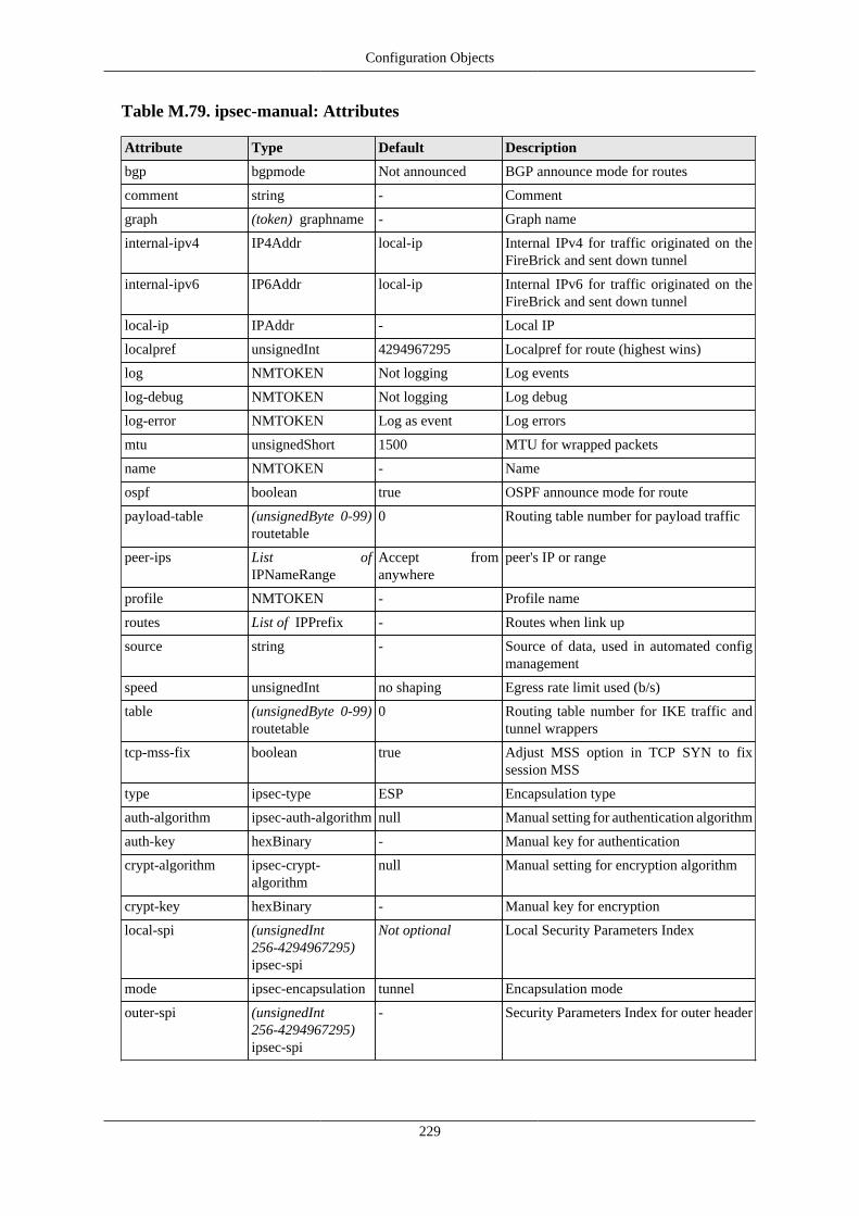
Configuration Objects
229
Table M.79. ipsec-manual: Attributes
Attribute Type Default Description
bgp bgpmode Not announced BGP announce mode for routes
comment string - Comment
graph (token) graphname - Graph name
internal-ipv4 IP4Addr local-ip Internal IPv4 for traffic originated on theFireBrick and sent down tunnel
internal-ipv6 IP6Addr local-ip Internal IPv6 for traffic originated on theFireBrick and sent down tunnel
local-ip IPAddr - Local IP
localpref unsignedInt 4294967295 Localpref for route (highest wins)
log NMTOKEN Not logging Log events
log-debug NMTOKEN Not logging Log debug
log-error NMTOKEN Log as event Log errors
mtu unsignedShort 1500 MTU for wrapped packets
name NMTOKEN - Name
ospf boolean true OSPF announce mode for route
payload-table (unsignedByte 0-99)routetable
0 Routing table number for payload traffic
peer-ips List ofIPNameRange
Accept fromanywhere
peer's IP or range
profile NMTOKEN - Profile name
routes List of IPPrefix - Routes when link up
source string - Source of data, used in automated configmanagement
speed unsignedInt no shaping Egress rate limit used (b/s)
table (unsignedByte 0-99)routetable
0 Routing table number for IKE traffic andtunnel wrappers
tcp-mss-fix boolean true Adjust MSS option in TCP SYN to fixsession MSS
type ipsec-type ESP Encapsulation type
auth-algorithm ipsec-auth-algorithm null Manual setting for authentication algorithm
auth-key hexBinary - Manual key for authentication
crypt-algorithm ipsec-crypt-algorithm
null Manual setting for encryption algorithm
crypt-key hexBinary - Manual key for encryption
local-spi (unsignedInt256-4294967295)ipsec-spi
Not optional Local Security Parameters Index
mode ipsec-encapsulation tunnel Encapsulation mode
outer-spi (unsignedInt256-4294967295)ipsec-spi
- Security Parameters Index for outer header

Configuration Objects
230
remote-spi (unsignedInt256-4294967295)ipsec-spi
Not optional Peer Security Parameters Index
Table M.80. ipsec-manual: Elements
Element Type Instances Description
route ipsec-route Optional, unlimited Routes to apply to tunnel when up
M.2.59. ping: Ping/graph definitionBase ping config - additional ping targets set via web API or other means
Table M.81. ping: Attributes
Attribute Type Default Description
comment string - Comment
graph (token) graphname Not optional Graph name
ip IPNameAddr Not optional Far end IP
name string - Name
profile NMTOKEN - Profile name
size (unsignedInt0-1472) ping-size
0 Payload size
slow boolean Auto Slow polling
source string - Source of data, used in automated configmanagement
table (unsignedByte 0-99)routetable
0 Routing table number for sending pings
M.2.60. profile: Control profileGeneral on/off control profile used in various places in the config.
Table M.82. profile: Attributes
Attribute Type Default Description
and List of NMTOKEN - Active if all specified profiles are activeas well as all other tests passing, including'not'
comment string - Comment
control-switch-users List of NMTOKEN Any users Restrict users that have access to controlswitch
dongle List of NMTOKEN - 3G Dongle state (any of these are ppp up)
expect boolean none Defines state considered 'Good' and showngreen on status page
fb105 List of NMTOKEN - FB105 tunnel state (any of these active)
initial boolean true Defines state at system startup if not usingset, or initial state of a new control switch
interval duration 1 Time between tests

Configuration Objects
231
invert boolean - Invert final result of testing
l2tp List of NMTOKEN - Outgoing L2TP link state (any of these areup)
led Colour - LED colour when active (or not expectedstate, if expect is set)
log NMTOKEN Not logging Log target
log-debug NMTOKEN Not logging Log additional information
name NMTOKEN Not optional Profile name
not NMTOKEN - Active if specified profile is inactive as wellas all other tests passing, including 'and'
or List of NMTOKEN - Active if any of these other profiles areactive regardless of other tests (including'not' or 'and')
ports Set of port - Test passes if any of these physical portsare up
ppp List of NMTOKEN - PPP link state (any of these are up)
recover duration 1 Time before recover (i.e. how long test hasbeen passing)
route List of IPAddr - Test passes if all specified addresses arerouteable
set switch - Manual override. Test settings ignored;Control switches can use and/or/not/invert
source string - Source of data, used in automated configmanagement
table (unsignedByte 0-99)routetable
- Routing table for ping/route
timeout duration 10 Time before timeout (i.e. how long test hasbeen failing)
vrrp List of NMTOKEN - VRRP state (any of these is master)
Table M.83. profile: Elements
Element Type Instances Description
date profile-date Optional, unlimited Test passes if within any date rangespecified
ping profile-ping Optional Test passes if address is answering pings
time profile-time Optional, unlimited Test passes if within any time rangespecified
M.2.61. profile-date: Test passes if within any of thetime ranges specified
Time range test in profiles
Table M.84. profile-date: Attributes
Attribute Type Default Description
comment string - Comment

Configuration Objects
232
source string - Source of data, used in automated configmanagement
start dateTime - Start (YYYY-MM-DDTHH:MM:SS)
stop dateTime - End (YYYY-MM-DDTHH:MM:SS)
M.2.62. profile-time: Test passes if within any of thedate/time ranges specified
Time range test in profiles
Table M.85. profile-time: Attributes
Attribute Type Default Description
comment string - Comment
days Set of day - Which days of week apply, default all
source string - Source of data, used in automated configmanagement
start time - Start (HH:MM:SS)
stop time - End (HH:MM:SS)
M.2.63. profile-ping: Test passes if any addresses arepingable
Ping targets
Table M.86. profile-ping: Attributes
Attribute Type Default Description
comment string - Comment
flow unsignedShort - Flow label (IPv6)
gateway IPAddr - Ping via specific gateway (bypasses sessiontracking if set)
ip IPAddr Not optional Target IP
source string - Source of data, used in automated configmanagement
source-ip IPAddr - Source IP
ttl unsignedByte - Time to live / Hop limit
M.2.64. shaper: Traffic shaperSettings for a named traffic shaper
Table M.87. shaper: Attributes
Attribute Type Default Description
comment string - Comment
name (token) graphname Not optional Graph name

Configuration Objects
233
rx unsignedInt - Rx rate limit/target (b/s)
rx-max unsignedInt - Rx rate limit max
rx-min unsignedInt - Rx rate limit min
rx-min-burst duration - Rx minimum allowed burst time
rx-step unsignedInt - Rx rate reduction per hour
share boolean - If shaper is shared with other devices
source string - Source of data, used in automated configmanagement
tx unsignedInt - Tx rate limit/target (b/s)
tx-max unsignedInt - Tx rate limit max
tx-min unsignedInt - Tx rate limit min
tx-min-burst duration - Tx minimum allowed burst time
tx-step unsignedInt - Tx rate reduction per hour
Table M.88. shaper: Elements
Element Type Instances Description
override shaper-override Optional, unlimited Profile specific variations on main settings
M.2.65. shaper-override: Traffic shaper override basedon profile
Settings for a named traffic shaper
Table M.89. shaper-override: Attributes
Attribute Type Default Description
comment string - Comment
profile NMTOKEN Not optional Profile name
rx unsignedInt - Rx rate limit/target (b/s)
rx-max unsignedInt - Rx rate limit max
rx-min unsignedInt - Rx rate limit min
rx-min-burst duration - Rx minimum allowed burst time
rx-step unsignedInt - Rx rate reduction per hour
source string - Source of data, used in automated configmanagement
tx unsignedInt - Tx rate limit/target (b/s)
tx-max unsignedInt - Tx rate limit max
tx-min unsignedInt - Tx rate limit min
tx-min-burst duration - Tx minimum allowed burst time
tx-step unsignedInt - Tx rate reduction per hour
M.2.66. ip-group: IP GroupNamed IP group

Configuration Objects
234
Table M.90. ip-group: Attributes
Attribute Type Default Description
comment string - Comment
ip List of IPRange - One or more IP ranges or IP/len
name string Not optional Name
source string - Source of data, used in automated configmanagement
users List of NMTOKEN - Include IP of (time limited) logged in webusers
M.2.67. route-override: Routing override rulesRouting override rules
Table M.91. route-override: Attributes
Attribute Type Default Description
comment string - Comment
name string - Name
source string - Source of data, used in automated configmanagement
table (unsignedByte 0-99)routetable
0 Applicable routing table
Table M.92. route-override: Elements
Element Type Instances Description
rule session-route-rule Optional, unlimited Individual rules, first match applies
M.2.68. session-route-rule: Routing override ruleRouting override rule
Table M.93. session-route-rule: Attributes
Attribute Type Default Description
comment string - Comment
cug List of PortRange - Closed user group ID(s)
hash boolean - Use hash of IPs for load sharing
name string - Name
profile NMTOKEN - Profile name
protocol List of unsignedByte - Protocol(s) [1=ICMP, 6=TCP, 17=UDP]
set-gateway IPAddr - New gateway
set-graph string - Graph name for shaping/logging (if not setby rule-set)
set-nat boolean - Changed source IP and port to local forNAT

Configuration Objects
235
source string - Source of data, used in automated configmanagement
source-interface List of NMTOKEN - Source interface(s)
source-ip List ofIPNameRange
- Source IP address range(s)
source-port List of PortRange - Source port(s)
target-interface List of NMTOKEN - Target interface(s)
target-ip List ofIPNameRange
- Target IP address range(s)
target-port List of PortRange - Target port(s)
Table M.94. session-route-rule: Elements
Element Type Instances Description
share session-route-share Optional, unlimited Load shared actions
M.2.69. session-route-share: Route override loadsharing
Route override setting for load sharing
Table M.95. session-route-share: Attributes
Attribute Type Default Description
comment string - Comment
profile NMTOKEN - Profile name
set-gateway IPAddr - New gateway
set-graph string - Graph name for shaping/logging (if not setby rule-set)
set-nat boolean - Changed source IP and port to local forNAT
weight positiveInteger 1 Weighting of load share
M.2.70. rule-set: Firewall/mapping rule setFirewalling rule set with entry criteria and default actions
Table M.96. rule-set: Attributes
Attribute Type Default Description
comment string - Comment
cug List of PortRange - Closed user group ID(s)
interface List of NMTOKEN - Source or target interface(s)
ip List ofIPNameRange
- Source or target IP address range(s)
log NMTOKEN Not logging Log session start
log-end NMTOKEN Not logging Log session end

Configuration Objects
236
log-no-match NMTOKEN log-start Log if no match
name string - Name
no-match-action firewall-action Not optional Default if no rule matches
profile NMTOKEN - Profile name
protocol List of unsignedByte - Protocol(s) [1=ICMP, 6=TCP, 17=UDP]
source string - Source of data, used in automated configmanagement
source-interface List of NMTOKEN - Source interface(s)
source-ip List ofIPNameRange
- Source IP address range(s)
source-port List of PortRange - Source port(s)
startup-delay duration 1:00 Startup interval to use ignore instead ofreject/drop
table (unsignedByte 0-99)routetable
0 Applicable routing table
target-interface List of NMTOKEN - Target interface(s)
target-ip List ofIPNameRange
- Target IP address range(s)
target-port List of PortRange - Target port(s)
Table M.97. rule-set: Elements
Element Type Instances Description
ip-group ip-group Optional, unlimited Named IP groups
rule session-rule Optional, unlimited Individual rules, first match applies
M.2.71. session-rule: Firewall rulesFirewall rule
The individual firewall rules are checked in order within the rule-set, and the first match applied. The defaultaction for a rule is continue, so once matched the next rule-set is considered.
Table M.98. session-rule: Attributes
Attribute Type Default Description
action firewall-action continue Action taken on match
comment string - Comment
cug List of PortRange - Closed user group ID(s)
hash boolean - Use hash of IPs for load sharing
interface List of NMTOKEN - Source or target interface(s)
ip List ofIPNameRange
- Source or target IP address range(s)
log NMTOKEN As rule-set Log session start
log-end NMTOKEN As rule-set Log session end
name string - Name
pcp boolean - If mapped by NAT-PMP / PCP

Configuration Objects
237
profile NMTOKEN - Profile name
protocol List of unsignedByte - Protocol(s) [1=ICMP, 6=TCP, 17=UDP]
set-gateway IPAddr - New gateway
set-graph string - Graph name for shaping/logging
set-graph-dynamic dynamic-graph - Dynamically create graph
set-initial-timeout duration - Initial time-out
set-nat boolean - Changed source IP and port to local forNAT
set-ongoing-timeout duration - Ongoing time-out
set-reverse-graph string - Graph name for shaping/logging (far sideof session)
set-source-ip IPRange - New source IP
set-source-port unsignedShort - New source port
set-table (unsignedByte 0-99)routetable
- Set new routing table
set-target-ip IPRange - New target IP
set-target-port unsignedShort - New target port
source string - Source of data, used in automated configmanagement
source-interface List of NMTOKEN - Source interface(s)
source-ip List ofIPNameRange
- Source IP address range(s)
source-mac List up to12 (hexBinary)macprefix
- Source MAC check if from Ethernet
source-port List of PortRange - Source port(s)
target-interface List of NMTOKEN - Target interface(s)
target-ip List ofIPNameRange
- Target IP address range(s)
target-port List of PortRange - Target port(s)
Table M.99. session-rule: Elements
Element Type Instances Description
share session-share Optional, unlimited Load shared actions
M.2.72. session-share: Firewall load sharingFirewall actions for load sharing
Table M.100. session-share: Attributes
Attribute Type Default Description
comment string - Comment
profile NMTOKEN - Profile name
set-gateway IPAddr - New gateway

Configuration Objects
238
set-graph string - Graph name for shaping/logging
set-nat boolean - Changed source IP and port to local forNAT
set-reverse-graph string - Graph name for shaping/logging (far sideof session)
set-source-ip IPRange - New source IP
set-source-port unsignedShort - New source port
set-table (unsignedByte 0-99)routetable
- Set new routing table
set-target-ip IPRange - New target IP
set-target-port unsignedShort - New target port
weight positiveInteger 1 Weighting of load share
M.2.73. voip: Voice over IP configVoice over IP config
Table M.101. voip: Attributes
Attribute Type Default Description
area-code string - Local area code (without national prefix)
auth-source-ip4 IP4Addr - Default IPv4 source address to use whensending authenticated messages
auth-source-ip6 IP6Addr - Default IPv6 source address to use whensending authenticated messages
backup-carrier NMTOKEN - Backup carrier to use for external calls
call-progress boolean true Send call progress at 3 seconds
comment string - Comment
country string 44 Local country code
default-carrier NMTOKEN - Default carrier to use for external calls
domain string - Domain to use for us on outgoing SIPconnections
emergency List of string 112 999 Emergency numbers
emergency-uri string Use outbound carrier SIP URI for emergency calls
international string 00 International dialling prefix
local-digits string 23456789 Local numbers start with these digits
local-min-len unsignedByte 5 Local numbers min length
log NMTOKEN Not logging Log calls
log-cdr NMTOKEN Not logged Log CDR records
log-debug NMTOKEN Not logging Log debug and SIP messages
log-error NMTOKEN Log as event Log errors
log-sip-blf NMTOKEN Not logged SUBSCRIBE, NOTIFY, PUBLISH
log-sip-call NMTOKEN Not logged INVITE, ACK, CANCEL, BYE, REFER
log-sip-other NMTOKEN Not logged OPTIONS, INFO, etc
log-sip-register NMTOKEN Not logged REGISTER

Configuration Objects
239
long-headers boolean false Send long SIP headers
max-ring duration 5:00 Max time limit on call setup
national string 0 National dialling prefix
pabx boolean true Operate as office PABX
pickup string * Call pickup/steal prefix
radius-call string - Name for RADIUS server config to use callrouting
radius-cdr string - Name for RADIUS server config to use forCDRs
radius-challenge boolean - Send RADIUS auth to get challengeresponse
radius-register string - Name for RADIUS server config to use forregistrations
realm string FireBrick Default realm
record-beep record-beep-option true Send beep at start of recording
record-mandatory boolean - Drop call if recording fails
record-server string - Call recording server hostname or address
release string 1470 CLI release prefix
security-replies boolean true Don't challenge or error reply tounrecognised non local IP request
send-pre-auth boolean true Send Auth header with username beforereceiving challenge
source string - Source of data, used in automated configmanagement
source-ip4 IP4Addr - Default IPv4 source address to use whensending messages
source-ip6 IP6Addr - Default IPv6 source address to use whensending messages
user-agent string Version specific User-Agent to send
withhold string 141 CLI withhold prefix
wrap-headers boolean true Wrap long SIP header lines
Table M.102. voip: Elements
Element Type Instances Description
carrier carrier Optional, up to 250 VoIP carriers
group ringgroup Optional, up to 50 Ring groups
telephone telephone Optional, up to 250 VoIP users
tone tone Optional, up to 25 Defined tones
M.2.74. carrier: VoIP carrier detailsVoIP carrier details
Table M.103. carrier: Attributes
Attribute Type Default Description

Configuration Objects
240
allow List ofIPNameRange
Allow fromanywhere
List of IP ranges from which inviteaccepted
cli-format voip-format national CLI number format for outgoing calls
comment string - Comment
cui string - Chargeable user identity for call accountingof incoming calls
display-name string - Text name to use
expires duration 1:00:00 Registration expiry time
extn string - Local number assumed for incoming call,use X for digits from end of called numbers
force-dtmf boolean - Always send DTMF in-band
from string - From SIP address for outbound registrationand invites
hold-tone boolean true Send hold tones to carrier
incoming-format voip-format national Dialled number format for incoming calls
map-404 (unsignedShort400-699) sip-error
- Map SIP error 404 to an alternative
max-calls unsignedInt - Maximum simultaneous calls allowed
name NMTOKEN Not optional Carrier name
outgoing-format voip-format national Dialled number format for outgoing calls
password Secret - Carrier password for outbound registrationor inbound authenticated calls
profile NMTOKEN - Profile name
proxy string - Carrier proxy hostname or address forregistration and calls
registrar string - Carrier hostname for registration
send-hold boolean true Pass hold state to carrier
send-pre-auth boolean As general config Send Auth header with username beforereceiving challenge
source string - Source of data, used in automated configmanagement
source-ip IPAddr - Source IP to use
table (unsignedByte 0-99)routetable
0 Routing table number
to List of string - To SIP request address for inbound invites,may be @domain for any at a domain
tone-hold string - Name of tone to generate for hold with nomedia
tone-progress string - Name of tone to generate for progress withno media
tone-queue string - Name of tone to generate for queue with nomedia
tone-ring string - Name of tone to generate for ring with nomedia

Configuration Objects
241
tone-wait string - Name of tone to generate for wait with nomedia
trust-cli boolean true Trust inbound calling line identity
username string - Carrier username for outbound registrationor inbound authenticated calls
withhold string - Mark withheld outbound calls using thisdial prefix and send CLI in remote party id
M.2.75. telephone: VoIP telephone authentication userdetails
VoIP telephone details
Table M.104. telephone: Attributes
Attribute Type Default Description
allow List ofIPNameRange
Allow fromanywhere
List of IP ranges from which registrationaccepted
allow-pickup List of string Allow all if PABXmode
Only allow pickup from these extensions
allow-subscribe List of string - Only allow subscribe (Busy Lamp Field)from these extensions
anon-numeric boolean - Mark anonymous calls just using withholdprefix, and leave display name
area-code string - Local area code (without national prefix)for use from this phone
carrier NMTOKEN - Carrier to use for outbound calls
cli-format voip-format auto CLI number format passed to telephone
comment string - Comment
cui string - Chargeable user identity for call accounting
ddi string - Full telephone number (internationalformat starting +)
display-name string - Text name to use
email string - Email address (sent to call recordingserver)
expires duration 1:00:00 Registration expiry time
extn string - Local extension number
force-dtmf boolean - Always send DTMF in-band
local-only boolean true Restrict access to registrations fromEthernet subnets only
max-calls unsignedInt - Maximum simultaneous calls allowed
name NMTOKEN Not optional User name (local part of 'from')
password Secret - Authentication password
profile NMTOKEN - Profile name
realm string - Realm
record recordoption - Automatically record calls

Configuration Objects
242
source string - Source of data, used in automated configmanagement
table (unsignedByte 0-99)routetable
0 Routing table number
uk-cli-text uknumberformat Auto Send display name as UK formattednumber
uri string - Direct URI for extn
username string - Authentication username
wrap-up duration - Wrap up time before new call
M.2.76. tone: Tone definitionsDefinition of tones used
Table M.105. tone: Attributes
Attribute Type Default Description
name NMTOKEN Not optional Tone name
plan string Not optional Plan for frequency and duration, e.g.400ms@400Hz-3dB+450Hz-3dB
M.2.77. ringgroup: Ring groupsRing groups
Table M.106. ringgroup: Attributes
Attribute Type Default Description
allow-pickup List of string - Only allow pickup from these extensions
allow-subscribe List of string - Only allow subscribe (Busy Lamp Field)from these extensions
answer-time duration 30 Answer caller if ringing this long
carrier NMTOKEN - Carrier to use for external calls
comment string - Comment
cui string - Chargeable user identity for call accounting
ddi List of string - Full telephone number (internationalformat starting +)
display-name string - Text name to use
email string - Email address (sent to call recordingserver)
extn List of string - Local extension number
initial-time duration - Don't progress to second number until thistime
limit unsignedByte - Number allowed to queue
name NMTOKEN Not optional Group name
order ring-group-order strict Order of ring
out-of-hours-group NMTOKEN - Alternative group if this is out of profile(cascades)

Configuration Objects
243
out-of-hours-ring List of string - Numbers to ring if out of profile and no out-of-hours-group set
overflow List of string - Numbers to ring when more than one callin queue
overflow-time duration 30 Include overflow after this time at head ofqueue
profile NMTOKEN - Profile name
progress-time duration 6 Time between each target called
redirect boolean - Allow calls to be diverted before ringing
ring List of string - Numbers to ring
ringall-time duration - Switch to ring all after this time at head ofqueue
source string - Source of data, used in automated configmanagement
type ring-group-type all Type of ring when one call in queue
M.2.78. etun: Ether tunnel
Ether tunnel
Table M.107. etun: Attributes
Attribute Type Default Description
eth-port NMTOKEN Not optional Port group name
ip IPAddr Not optional Far end IP address
log NMTOKEN Not logging Log events
log-debug NMTOKEN Not logging Log debug
log-error NMTOKEN Log as event Log errors
name string - Name
profile NMTOKEN - Profile name
source-ip IPAddr - Our IP address
table (unsignedByte 0-99)routetable
0 Routing table number
M.2.79. dhcp-relay: DHCP server settings for remote /relayed requests
Settings for DHCP server for relayed connections
Table M.108. dhcp-relay: Attributes
Attribute Type Default Description
allocation-table (unsignedByte 0-99)routetable
Allocate same asrequest table
Routing table for allocations - suggestusing separate tables for remote DHCP
allow List ofIPNameRange
Allow fromanywhere
IPs allowed (e.g. allocated IPs for renewal)

Configuration Objects
244
relay List ofIPNameRange
Any relay Relay server IP(s)
table (unsignedByte 0-99)routetable
Allow any Routing table applicable
Table M.109. dhcp-relay: Elements
Element Type Instances Description
dhcp dhcps Optional, unlimited DHCP server settings
M.3. Data types
M.3.1. autoloadtype: Type of s/w auto load
Table M.110. autoloadtype: Type of s/w auto load
Value Description
false Do no auto load
factory Load factory releases
beta Load beta test releases
alpha Load test releases
M.3.2. config-access: Type of access user has toconfig
Table M.111. config-access: Type of access user has to config
Value Description
none No access unless explicitly listed
view View only access (no passwords)
read Read only access (with passwords)
full Full view and edit access
M.3.3. user-level: User login level
User login level - commands available are restricted according to assigned level.
Table M.112. user-level: User login level
Value Description
NOBODY Unknown or not logged in user
GUEST Guest user
USER Normal unprivileged user
ADMIN System administrator
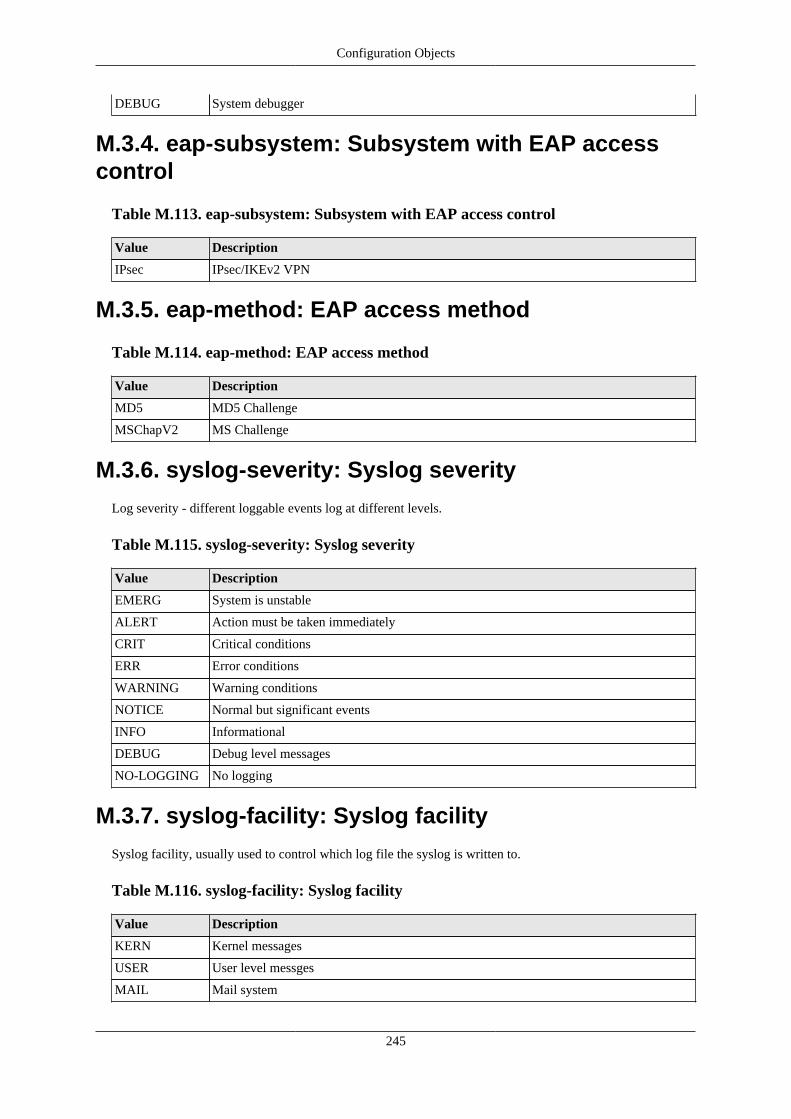
Configuration Objects
245
DEBUG System debugger
M.3.4. eap-subsystem: Subsystem with EAP accesscontrol
Table M.113. eap-subsystem: Subsystem with EAP access control
Value Description
IPsec IPsec/IKEv2 VPN
M.3.5. eap-method: EAP access method
Table M.114. eap-method: EAP access method
Value Description
MD5 MD5 Challenge
MSChapV2 MS Challenge
M.3.6. syslog-severity: Syslog severity
Log severity - different loggable events log at different levels.
Table M.115. syslog-severity: Syslog severity
Value Description
EMERG System is unstable
ALERT Action must be taken immediately
CRIT Critical conditions
ERR Error conditions
WARNING Warning conditions
NOTICE Normal but significant events
INFO Informational
DEBUG Debug level messages
NO-LOGGING No logging
M.3.7. syslog-facility: Syslog facility
Syslog facility, usually used to control which log file the syslog is written to.
Table M.116. syslog-facility: Syslog facility
Value Description
KERN Kernel messages
USER User level messges
MAIL Mail system

Configuration Objects
246
DAEMON System Daemons
AUTH Security/auth
SYSLOG Internal to syslogd
LPR Printer
NEWS News
UUCP UUCP
CRON Cron deamon
AUTHPRIV private security/auth
FTP File transfer
12 Unused
13 Unused
14 Unused
15 Unused
LOCAL0 Local 0
LOCAL1 Local 1
LOCAL2 Local 2
LOCAL3 Local 3
LOCAL4 Local 4
LOCAL5 Local 5
LOCAL6 Local 6
LOCAL7 Local 7
M.3.8. http-mode: HTTP/HTTPS security mode
Table M.117. http-mode: HTTP/HTTPS security mode
Value Description
http-only No HTTPS access
http+https Both HTTP and HTTPS access
https-only No HTTP access
redirect-to-https HTTP accesses are redirected to use HTTPS
redirect-to-https-if-acme
HTTP accesses are redirected to use HTTPS if ACME set up for hostname
redirect-to-https-except-trusted
HTTP accesses are redirected to use HTTPS (except trusted IPs)
M.3.9. radiuspriority: Options for controlling platformRADIUS response priority tagging
Table M.118. radiuspriority: Options for controlling platform RADIUS responsepriority tagging
Value Description
equal All the same priority
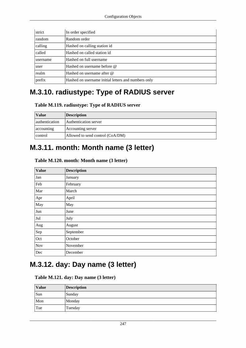
Configuration Objects
247
strict In order specified
random Random order
calling Hashed on calling station id
called Hashed on called station id
username Hashed on full username
user Hashed on username before @
realm Hashed on username after @
prefix Hashed on username initial letters and numbers only
M.3.10. radiustype: Type of RADIUS server
Table M.119. radiustype: Type of RADIUS server
Value Description
authentication Authentication server
accounting Accounting server
control Allowed to send control (CoA/DM)
M.3.11. month: Month name (3 letter)
Table M.120. month: Month name (3 letter)
Value Description
Jan January
Feb February
Mar March
Apr April
May May
Jun June
Jul July
Aug August
Sep September
Oct October
Nov November
Dec December
M.3.12. day: Day name (3 letter)
Table M.121. day: Day name (3 letter)
Value Description
Sun Sunday
Mon Monday
Tue Tuesday

Configuration Objects
248
Wed Wednesday
Thu Thursday
Fri Friday
Sat Saturday
M.3.13. port: Physical port
Table M.122. port: Physical port
Value Description
0 Port 0 (not valid) (deprecated)
1 Port 1
2 Port 2
3 Port 3
4 Port 4
5 Port 5
M.3.14. Crossover: Crossover configuration
Physical port crossover configuration.
Table M.123. Crossover: Crossover configuration
Value Description
auto Crossover is determined automatically
MDI Force no crossover
M.3.15. LinkSpeed: Physical port speed
Table M.124. LinkSpeed: Physical port speed
Value Description
10M 10Mbit/sec
100M 100Mbit/sec
1G 1Gbit/sec
auto Speed determined by autonegotiation
M.3.16. LinkDuplex: Physical port duplex setting
Table M.125. LinkDuplex: Physical port duplex setting
Value Description
half Half-duplex
full Full-duplex
auto Duplex determined by autonegotiation

Configuration Objects
249
M.3.17. LinkFlow: Physical port flow control setting
Table M.126. LinkFlow: Physical port flow control setting
Value Description
none No flow control
symmetric Can support two-way flow control
send-pauses Can send pauses but does not support pause reception
any Can receive pauses and may send pauses if required
M.3.18. LinkClock: Physical port Gigabit clock master/slave setting
Table M.127. LinkClock: Physical port Gigabit clock master/slave setting
Value Description
prefer-master Master status negotiated; preference for master
prefer-slave Master status negotiated; preference for slave
force-master Master status forced
force-slave Slave status forced
M.3.19. LinkLED: LED settings
Table M.128. LinkLED: LED settings
Value Description
Link/Activity Use settings from link-activity item
Off Permanently off
On Permanently on
Flash Flash
M.3.20. LinkPower: PHY power saving options
Table M.129. LinkPower: PHY power saving options
Value Description
none No power saving
full Full power saving
M.3.21. LinkFault: Link fault type to send
Table M.130. LinkFault: Link fault type to send
Value Description
false No fault
true Send fault
off-line Send offline fault (1G)

Configuration Objects
250
ane Send ANE fault (1G)
M.3.22. LEDColour: Which colour LED
Table M.131. LEDColour: Which colour LED
Value Description
orange
green
yellow
M.3.23. LEDBlink: LED blink speed
Table M.132. LEDBlink: LED blink speed
Value Description
Slow 2Hz
Medium 4Hz
Fast 8Hz
Linkspeed 10M=2Hz,100M=4Hz,1G=8Hz
M.3.24. sampling-protocol: Sampling protocol
Table M.133. sampling-protocol: Sampling protocol
Value Description
sflow Use sFlow protocol
ipfix-psamp Use IPFIX/PSAMP protocol
ipfix-legacy Use legacy (Cisco-style) IPFIX
M.3.25. trunk-mode: Trunk port mode
Table M.134. trunk-mode: Trunk port mode
Value Description
false Not trunking
random Random trunking
l2-hash L2 hashed trunking
l23-hash L2 and L3 hashed trunking
l3-hash L3 hashed trunking
M.3.26. ramode: IPv6 route announce levelIPv6 route announcement mode and level
Table M.135. ramode: IPv6 route announce level
Value Description
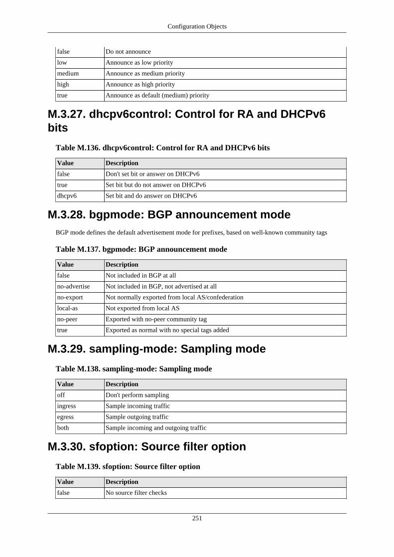
Configuration Objects
251
false Do not announce
low Announce as low priority
medium Announce as medium priority
high Announce as high priority
true Announce as default (medium) priority
M.3.27. dhcpv6control: Control for RA and DHCPv6bits
Table M.136. dhcpv6control: Control for RA and DHCPv6 bits
Value Description
false Don't set bit or answer on DHCPv6
true Set bit but do not answer on DHCPv6
dhcpv6 Set bit and do answer on DHCPv6
M.3.28. bgpmode: BGP announcement modeBGP mode defines the default advertisement mode for prefixes, based on well-known community tags
Table M.137. bgpmode: BGP announcement mode
Value Description
false Not included in BGP at all
no-advertise Not included in BGP, not advertised at all
no-export Not normally exported from local AS/confederation
local-as Not exported from local AS
no-peer Exported with no-peer community tag
true Exported as normal with no special tags added
M.3.29. sampling-mode: Sampling mode
Table M.138. sampling-mode: Sampling mode
Value Description
off Don't perform sampling
ingress Sample incoming traffic
egress Sample outgoing traffic
both Sample incoming and outgoing traffic
M.3.30. sfoption: Source filter option
Table M.139. sfoption: Source filter option
Value Description
false No source filter checks
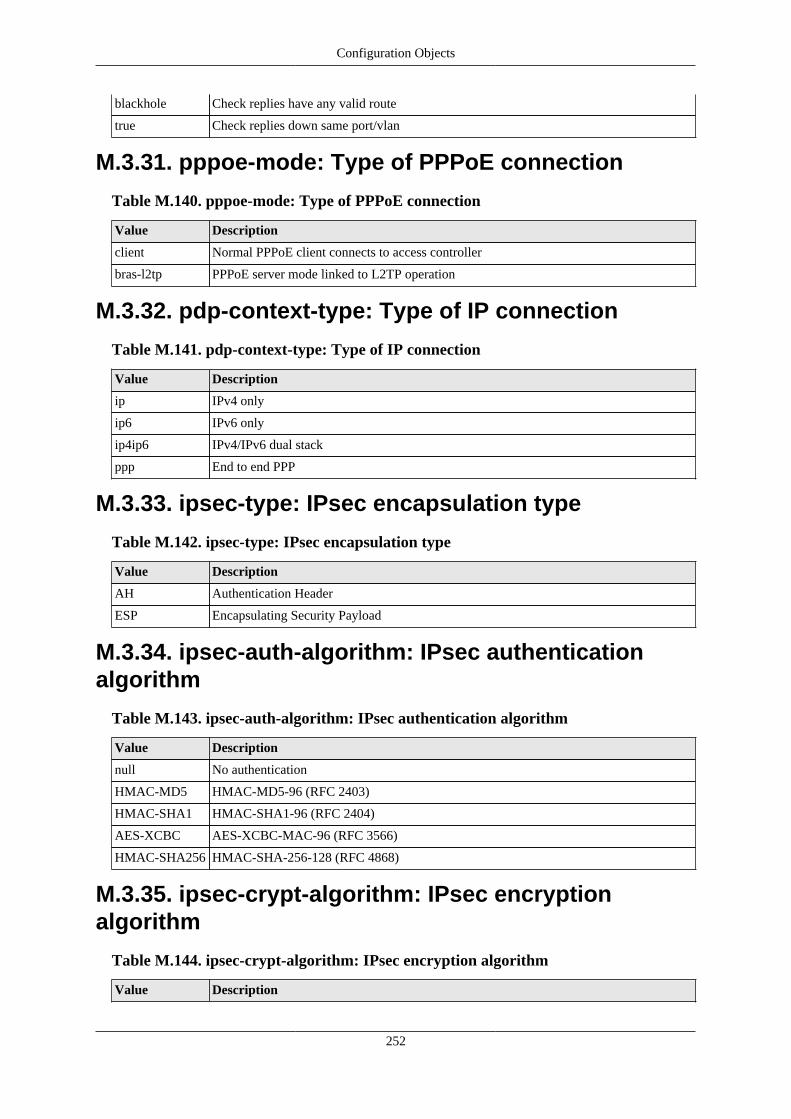
Configuration Objects
252
blackhole Check replies have any valid route
true Check replies down same port/vlan
M.3.31. pppoe-mode: Type of PPPoE connection
Table M.140. pppoe-mode: Type of PPPoE connection
Value Description
client Normal PPPoE client connects to access controller
bras-l2tp PPPoE server mode linked to L2TP operation
M.3.32. pdp-context-type: Type of IP connection
Table M.141. pdp-context-type: Type of IP connection
Value Description
ip IPv4 only
ip6 IPv6 only
ip4ip6 IPv4/IPv6 dual stack
ppp End to end PPP
M.3.33. ipsec-type: IPsec encapsulation type
Table M.142. ipsec-type: IPsec encapsulation type
Value Description
AH Authentication Header
ESP Encapsulating Security Payload
M.3.34. ipsec-auth-algorithm: IPsec authenticationalgorithm
Table M.143. ipsec-auth-algorithm: IPsec authentication algorithm
Value Description
null No authentication
HMAC-MD5 HMAC-MD5-96 (RFC 2403)
HMAC-SHA1 HMAC-SHA1-96 (RFC 2404)
AES-XCBC AES-XCBC-MAC-96 (RFC 3566)
HMAC-SHA256 HMAC-SHA-256-128 (RFC 4868)
M.3.35. ipsec-crypt-algorithm: IPsec encryptionalgorithm
Table M.144. ipsec-crypt-algorithm: IPsec encryption algorithm
Value Description

Configuration Objects
253
null No encryption (RFC 2410)
3DES-CBC 3DES-CBC (RFC 2451)
blowfish Blowfish CBC (RFC 2451) with 16-byte key
blowfish-192 Blowfish CBC (RFC 2451) with 24-byte key
blowfish-256 Blowfish CBC (RFC 2451) with 32-byte key
AES-CBC AES-CBC (Rijndael) (RFC 3602) with 16-byte key
AES-192-CBC AES-CBC (Rijndael) (RFC 3602) with 24-byte key
AES-256-CBC AES-CBC (Rijndael) (RFC 3602) with 32-byte key
M.3.36. peertype: BGP peer typePeer type controls many of the defaults for a peer setting. It allows typical settings to be defined with oneattribute that reflects the type of peer.
Table M.145. peertype: BGP peer type
Value Description
normal Normal BGP operation
transit EBGP Mark received as no-export
peer EBGP Mark received as no-export, only accept peer AS
customer EBGP Allow export as if confederate, only accept peer AS
internal IBGP allowing own AS
reflector IBGP allowing own AS and working in route reflector mode
confederate EBGP confederate
ixp Internet exchange point peer on route server, soft routes EBGP only
M.3.37. radius-nas: NAS IP to report
Table M.146. radius-nas: NAS IP to report
Value Description
false Local LNS IP (deprecated)
lns Local LNS IP
both Send NAS IP twice (LAC then LNS)
lac Remote LAC IP
true Remote LAC IP (deprecated)
M.3.38. ike-authmethod: authentication method
Table M.147. ike-authmethod: authentication method
Value Description
Secret Shared Secret
Certificate X.509 certificate
EAP Use EAP for authentication

Configuration Objects
254
M.3.39. ike-mode: connection setup mode
Table M.148. ike-mode: connection setup mode
Value Description
Wait Wait for peer to initiate the connection
On-demand Bring up when needed for traffic
Immediate Always attempt to bring up connection
M.3.40. ike-PRF: IKE Pseudo-Random Function
Table M.149. ike-PRF: IKE Pseudo-Random Function
Value Description
HMAC-MD5 HMAC-MD5
HMAC-SHA1 HMAC-SHA1
AES-XCBC-128 AES-XCBC with 128-bit key
HMAC-SHA256 PRF-HMAC-SHA-256 (rfc4868)
M.3.41. ike-DH: IKE Diffie-Hellman group
Table M.150. ike-DH: IKE Diffie-Hellman group
Value Description
none No D-H negotiation (only used with AH/ESP)
MODP-1024 1024-bit Sophie Germain Prime MODP Group
MODP-2048 2048-bit Sophie Germain Prime MODP Group
M.3.42. ike-ESN: IKE Sequence Number support
Table M.151. ike-ESN: IKE Sequence Number support
Value Description
ALLOW-ESN Allow Extended Sequence Numbers (64 bits)
ALLOW-SHORT-SN
Allow short sequence numbers (32 bits)
M.3.43. ipsec-encapsulation: Manually keyed IPsecencapsulation mode
Table M.152. ipsec-encapsulation: Manually keyed IPsec encapsulation mode
Value Description
tunnel IPsec tunnel
transport IPsec transport

Configuration Objects
255
M.3.44. switch: Profile manual settingManual setting control for profile
Table M.153. switch: Profile manual setting
Value Description
false Profile set to OFF
true Profile set to ON
control-switch Profile set based on control switch on home page
M.3.45. dynamic-graph: Type of dynamic graph
Table M.154. dynamic-graph: Type of dynamic graph
Value Description
false No dynamic graph
ip Use source IP address
mac Use source MAC address
M.3.46. firewall-action: Firewall action
Table M.155. firewall-action: Firewall action
Value Description
continue Continue rule-set checking
accept Allow but no more rule-set checking
reject End all rule checking now and set to send ICMP reject
drop End all rule checking now and set to drop
ignore End all rule checking and ignore (drop) just this packet, not making a session
M.3.47. voip-format: Number presentation format
Table M.156. voip-format: Number presentation format
Value Description
international Full international number
int-no-plus International without leading plus
national With nat/int prefix
local Local number/extension
transparent Unchanged
block Do not use for calls
M.3.48. uknumberformat: Number formatting option
Table M.157. uknumberformat: Number formatting option
Value Description

Configuration Objects
256
false Don't format numbers for display
true Format numbers for display with spacing
replace-zero Format numbers for display with spacing and replacing zeros - may look clearer on someCLI devices
M.3.49. recordoption: Recording option
Table M.158. recordoption: Recording option
Value Description
false Don't automatically record calls
in-only Automatically record incoming calls
out-only Automatically record outgoing calls
true Automatically record all calls
M.3.50. ring-group-order: Order of ring
Table M.159. ring-group-order: Order of ring
Value Description
strict Order in config
random Random order
cyclic Cycling from last call
oldest Oldest used phone first
M.3.51. ring-group-type: Type of ring when one call inqueue
Table M.160. ring-group-type: Type of ring when one call in queue
Value Description
all All phones
cascade Increasing number of phones
sequence One phone at a time
M.3.52. record-beep-option: Record beep option
Table M.161. record-beep-option: Record beep option
Value Description
false No beep
button Beep on record button press
true Beep on start of record

Configuration Objects
257
M.4. Basic typesTable M.162. Basic data types
Type Description
string text string
token text string
hexBinary hex coded binary data
integer integer (-2147483648-2147483647)
positiveInteger positive integer (1-4294967295)
unsignedInt unsigned integer (0-4294967295)
unsignedShort unsigned short integer (0-65535)
byte byte integer (-128-127)
unsignedByte unsigned byte integer (0-255)
boolean Boolean
dateTime YYYY-MM-DDTHH:MM:SS date/time
time HH:MM:SS time
NMTOKEN String with no spaces
void Internal use
IPAddr IP address
IPNameAddr IP address or name
IP4Addr IPv4 address
IP6Addr IPv6 address
IPPrefix IP address / bitlen
IPRange IP address / bitlen or range
IPNameRange IP address / bitlen or range or name
IP4Range IPv4 address / bitlen or range
IP4Prefix IPv4 address / bitlen
IP6Prefix IPv6 address / bitlen
IPSubnet IP address / bitlen
IP4Subnet IPv4 address / bitlen
IPFilter Route filter
Password Password
OTP OTP
Community xxx:xxx community
PortRange xxx-xxx port range
Colour #rgb #rrggbb #rgba #rrggbbaa colour
Secret Secret/passphrase
duration Period [[HH:]MM:]SS
percentage Percentage (0 .. 100) (0-100) (unsignedByte)
stringlist List of strings (string)
routetable Route table number (0-99) (unsignedByte)

Configuration Objects
258
username Login name (NMTOKEN)
ipnamerangelist List of IPranges or ip groups (IPNameRange)
nmtokenlist List of NMTOKEN (NMTOKEN)
iplist List of IP addresses (IPAddr)
ipnamelist List of IP addresses or domain names (IPNameAddr)
datenum Day number in month (1-31) (unsignedByte)
sample-rate Sampling rate (100-10000) (unsignedShort)
mtu Max transmission unit (576-2000) (unsignedShort)
subnetlist List of subnets (IPSubnet)
ra-max Route announcement max interval (seconds) (4-1800) (unsignedShort)
ra-min Route announcement min interval (seconds) (3-1350) (unsignedShort)
ip6list List of IPv6 addresses (IP6Addr)
vlan VLAN ID (0=untagged) (0-4095) (unsignedShort)
ip4rangelist List of IP4ranges (IP4Range)
macprefixlist List of strings (macprefix)
macprefix MAC prefix (hexBinary)
ip4list List of IPv4 addresses (IP4Addr)
graphname Graph name (token)
cug CUG ID (1-32767) (unsignedShort)
prefixlist List of IP Prefixes (IPPrefix)
aslist List of AS numbers (unsignedIntList)
unsignedIntList List of integers (unsignedInt)
communitylist List of BGP communities (Community)
ipsec-spi IPsec Security Parameters Index (256-4294967295) (unsignedInt)
filterlist List of IP Prefix filters (IPFilter)
bgp-prefix-limit Maximum prefixes accepted on BGP session (1-10000) (unsignedInt)
fb105-reorder-timeout
Maximum time to queue out of order packet (ms) (10-5000) (unsignedInt)
fb105-reorder-maxq Maximum size of out of order packet queue (1-100) (unsignedInt)
hex32 Hex value up to 32 bits (4 bytes) (hexBinary)
iprangelist List of IPranges (IPRange)
ping-size Data payload size to be sent in ping packet (0-1472) (unsignedInt)
portlist List of protocol port ranges (PortRange)
protolist List of IP protocols (unsignedByte)
sip-error SIP error code (400-699) (unsignedShort)
userlist List of user names (username)
prefix4list List of IPv4 Prefixes (IP4Prefix)
routetableset Set of routetables (routetable)
vlan-nz VLAN ID (1-4095) (unsignedShort)
dates Set of dates (datenum)
tun-id Local tunnel ID (1-100) (unsignedShort)

Configuration Objects
259
ses-id Local session ID (1-500) (unsignedShort)
hostname Host name (NMTOKEN)

260
IndexSymbols3G
USB dongle configuration, 95
BBGP
overview, 123Boot process, 31Breadcrumbs, 15
CConfiguration
backing up and restoring, 19categories (user interface), 16Data types in config, 11methods, 11overview, 10overview of using XML, 19transferring using HTTP client, 22using web user interface, 14
Configuration Basic data types , 256Configuration Data types , 244Configuration Field definitions , 187
DDHCP
configuring server, 41configuring subnet with DHCP client, 41Relay Agent, 44
DiagnosticsAccess check, 104Firewalling check, 103Packet dumping, 104
DNSconfiguring resolver(s) to use, 99
EEther tunnel
overview, 94Ethernet Ports
configuring LED indication modes, 44configuring speed and/or duplex modes, 44defining port groups, 39relationship with interfaces, 38sequenced flashing of LEDs, 32
Event loggingexternal logging, 34overview, 33viewing logs, 36
FFirewall
definition of, 48Firewalling
recommended method, 54
GGlobal LED control, 31Graphs, 69
HHostname
setting, 27HTTP service
configuration, 97
IInterfaces
defining, 39Ethernet, 38relationship with physical ports, 38
Internet Service Providersoverview, 132
LLEDs
Status LED - indications, 31Log targets, 33Logging (see Event logging)
NNAT
Using, 58Navigation buttons
in user interface, 18NTP (Network Time Protocol)
configuring time servers to use, 100
OObject Hierarchy
overview, 10Object Model
definition of, 10formal definition, 11
OSPFoverview, 130
PPacket dumping, 104
Example using curl and tcpdump, 107PPPoE
configuring, 73overview, 72
Profilesdefining, 66overview, 66

Index
261
viewing current state, 66
RRADIUS
configuring service, 101Route
definition of, 62Router
definition of, 48Routing
route targets, 63Rule-Sets
defining, 53
SSession Rules
defining, 53overview, 49processing flow, 50processing flow-chart, 51
Session Table, 48Session Tracking
changes to session traffic, 55configuring time-outs, 56load balancing, 57NAT-PMP / PCP, 57overview, 48time-outs, 49
Shapers, 70SNMP
configuring service, 100Software
identifying current version, 29Software upgrades
breakpoint releases, 28controlling auto-upgrade behaviour, 30overview, 28software release types, 28
System name (see Hostname)System services
checking access to, 104configuring, 96definition of, 96list of, 96
TTelnet service
configuration, 99Time-out
login sessions, 25Traffic shaping
overview, 69Tunnels
bonding (FB105), 93FB105, 91viewing status (FB105), 92
UUSB
"socket" identification value, 953G dongle configuration, 95overview, 95subsystem, configuration, 95
User Interfacecustomising layout, 15general layout, 14navigation, 18overview, 14
Userscreating / configuring, 24login level, 24restricting logins by IP address, 25
VVirtual Router Redundancy Protocol (VRRP), 108
virtual router, definition of, 108VRRP versions, 109
VLANsintroduction to, 149
VoIPbasics, 111CDR, 120NAT, 112overview, 111registration, 111technical, 121
XXML
introduction to, 19XML Schema Document (XSD) file, 11