iv. university research
TRANSCRIPT

iv. universitY reseArch
FY 2007 Progress Report 27� Advanced Combustion Engine Technologies

Advanced Combustion Engine Technologies 27� FY 2007 Progress Report

IV.1 Consortium on Low-Temperature Combustion for High-Efficiency, Ultra-Low Emission Engines
Dennis Assanis University of Michigan (UM) Mechanical Engineering 2045 W.E.Lay Auto. Lab. 1231 Beal Avenue Ann Arbor, MI 48109-2133
DOE Technology Development Manager: Gurpreet Singh
NETL Project Manager: Samuel Taylor
Subcontractors: • Massachusetts Institute of Technology (MIT),
Cambridge, MA • Stanford University (SU), Stanford, CA • University of California, Berkeley (UCB), Berkeley, CA
Objectives
• Investigate the fundamental processes that determine the practical boundaries of low-temperature combustion (LTC) engines.
• Develop methods to extend LTC boundaries to improve the fuel economy of homogeneous charge compression ignition (HCCI) engines fueled on gasoline and alternative blends, while operating with ultra low emissions.
• Investigate alternate fuels, ignition and after-treatment for premixed compression ignition (PCI) engines.
Accomplishments
• Multi-cylinder supercharged engine operation for high-load limit extension has been demonstrated using port fuel injection. Initial experiments up to 1.7 bar intake pressure have shown proportional load increases. Combustion control is provided by an intake air cooler/flow splitter arrangement.
• Single-cylinder experiments have achieved low-load extension by fuel injection during negative valve overlap (NVO). Further, varying the timing of the injection affects the combustion phasing and shows promise as a control tool.
• Different valve timing strategies for achieving HCCI have been explored using an engine simulation based on GT-Power® and enhanced with user-derived HCCI combustion and heat transfer models. Studies indicate that load limits are strongly affected
by complex interactions between sensible residual gas heat, effective compression ratio associated with the particular valve strategy employed, and cycle-tocycle feedback of residual gas.
• Spark assist has been shown to have an effect in stabilizing and controlling HCCI combustion under limit conditions. To investigate this effect, the interaction of a laminar flame and auto igniting gas has been modeled using HCT, a one dimensional transient reacting gas code. The results are consistent with the experimental findings, and by demonstrating the independence of the flame and autoignition process, point to relatively simple computational fluid dynamics (CFD) models of spark-assisted HCCI to be developed.
• Rapid compression ignition studies of several isomers of the biofuel component methyl-butanoate have been carried out. The results have been used to update a detailed kinetic model by Westbrook et al. at Lawrence Livermore National Laboratory (LLNL).
• An after-treatment model has been developed for PCI combustion products which successfully describes the performance of a production-type low-temperature diesel oxidation catalyst (DOC) under PCI and normal diesel operation.
Future Directions
• Carry out single- and multi-cylinder experimental investigations of upper and lower load combustion limits with supercharging/turbocharging and fast thermal management of intake temperature.
• Explore valve actuation and supercharging/ turbocharging implementations with the GT-Power®
system model and evaluate performance and fuel economy benefits.
• Develop model of spark-assisted HCCI and explore potential benefits of the technology from the point of view of control and range extension.
• Adapt after-treatment model to gasoline conditions and apply to HCCI system studies.
G G G G G
introduction
LTC is a new technology for internal combustion engines which promises to provide improved fuel economy with low emissions. With this technology, the engine is operated lean and cool enough to drastically
FY 2007 Progress Report 277 Advanced Combustion Engine Technologies

IV. University Research Assanis – University of Michigan
reduce NOx emissions and reduce particulate matter. In addition, operating lean allows high compression ratios for gasoline and reduces particulate emissions in diesels. The overall effect is to increase fuel economy for gasoline applications by up to 25%, and in the case of diesel engines, provide the means of satisfying the new, more stringent emissions regulations.
Because LTC implies operation at temperatures near the limit of flame propagation, reliable combustion must be initiated by auto-ignition which requires successful management of the thermal history of the engine and the gas charge. In principle, this can be achieved with adequate thermal management; control and various methods have been suggested for accomplishing this. However, as shown in Figure 1, full use of LTC has been limited at both high and low loads and threatens to reduce the ultimate fuel economy benefit that can be achieved in a vehicle system. At low load there is not enough heat in the charge to keep combustion healthy, while at high load the combustion is too rapid and may damage the engine structure. The focus of this consortium is to investigate the limit phenomena and to propose methods of extending the limits.
Approach
Our research project, in its second year, combines experiments and modeling at four university research centers in order to acquire the knowledge and technology to develop methods to extend the load range of LTC engines. To accomplish this, both single-cylinder and multi-cylinder engine experiments are investigating direct fuel injection strategies, turbocharging/
12
10
8
6
4
2
0
-2
0 2000 4000 6000
LTC
MAX. LOAD (W.O.T.)
FTP MAP
RANGE EXTENSION
RPM
FiGure 1. Performance map showing limited current achievable LTC range relative to a typical automotive range for maximum load over the FTP driving cycle.
BM
EP
(bar
) supercharging, and fast thermal management as possible approaches. Other tasks concentrate on spark-assisted LTC, and possible roles of alternate fuels. Recognizing the role of emission constraints particularly in the context of transient vehicle operation, studies of after-treatment devices are underway with specific application to the LTC environment both for HCCI and for PCI systems.
An array of modeling tools are being developed and refined, and brought to bear on the specific limit problems of importance. These models cover a range of detail from system models for engines and after-treatment devices, through detailed and reduced chemical mechanisms, to fully coupled CFD/kinetic models. Our intent is to take advantage of the broad range of capabilities of the university partners and the collaborative relationships among them.
results
HCCI Results
Engine Experiments on HCCI Limit Extension - Experiments at UCB with a four-cylinder engine have shown supercharged operation up to manifold absolute pressure of 1.7 bar. Initial results from this study are shown in Figure 2 for both gasoline and ethanol fuel, where indicated mean effective pressure (IMEP) is shown as a function of 50% burned combustion phasing (CA50) varied by adjusting the intake temperature with an intake flow splitter arrangement. The expected increase in load with manifold pressure is observed along with the characteristic fall off in IMEP with retarded combustion phasing. These tests were carried out at a constant equivalence ratio of 0.3. Future work
FiGure 2. Experimental timing sweeps measured on the UCB four-cylinder supercharged HCCI engine showing increased IMEP at higher manifold pressure. Tests carried out for both gasoline and ethanol fuel at an equivalence ratio of 0.3.
Advanced Combustion Engine Technologies 27� FY 2007 Progress Report

5 .21
E F K
01
7
01
9
EF K xON
Assanis – University of Michigan IV. University Research
will work towards higher equivalence ratios and load and will exercise the rapid thermal management flow system in real time.
Last year, experiments at Stanford University found that fuel injection during NVO has the potential to extend the low-load limit of HCCI operation to approximately 1 bar of net mean effective pressure (NMEP). The experiments were carried out on a variable valve actuation single-cylinder engine. It was found that when fuel is injected during this overlap period the ignition is advanced so that lower loads can be obtained. The mechanism for this enhancement is the partial release of energy due to pre-reaction of the injected fuel prior to the main intake and power stroke. This advances combustion and extends the lean limit. This year the studies have determined that the phasing of the injection is important and that earlier injection results in earlier combustion. The effect is greatest at
The model has been used to explore the load limits of several valve timing strategies for internal exhaust gas recirculation. Figure 3 shows the limit behavior of two strategies for providing residual gas fraction control: the first employs recompression or negative valve overlap; the second uses rebreathing enabled by a second exhaust valve event, open during the normal intake stroke. The
(a) RECOMPRESSION 7
6 1 leufgm81188 mmgg ffuuee ll FFEE KK NOx
1 5.51155..555
1122..55 MF/U 4
low equivalence ratios where there is an abundance of excess oxygen to support the pre-reaction. It is hoped that these findings will lead to improved combustion control at light load.
A third test facility is now in operation at MIT. N
MEP
(bar
) N
MEP
(bar
)
3
1100
772
5.4 This approach uses a computer-controlled turbocharger 1 4 5.44.5.5emulator to simulate a multi-cylinder application on
M B/FMM F/BQF/BQ
a single-cylinder engine. Experiments are just getting underway at that facility.
Modeling and Simulation Tools for HCCI - Last year we reported on a parametric study at UM of HCCI combustion carried out with a fully coupled CFD/ kinetic model. Extensive data was gathered from over 400 simulations for variables such as engine speed, equivalence ratio, turbulence level, wall temperature, and piston shape. The focus was on understanding the combustion broadening effect of the in-cylinder temperature distribution caused by heat transfer from the cylinder walls.
This year the CFD-generated results were used to develop a correlation of combustion burn rates and combustion efficiency that we have applied to a system study of HCCI limit behavior. This novel correlation is unique in that it includes not only the effect of main operating variables such as ignition timing, RPM, and equivalence ratio on burn rate variables, but also
0 -5 0 5 10 15 20
CA50 (deg ATC)
(b) REBREATHING 7
1 l eufgm8118 mg fuel8 mg fuel FFE KE K NN OxOx6
1 5.5115.55.55
4 MF/U
1 5.2112.52.5
11003
992 M QB/FMM F/BQF/BQ
includes the physically plausible finding that combustion efficiency is primarily a function of peak cylinder temperature. Ignition is described by a suitable auto-ignition integral developed earlier.
The combustion correlation was incorporated into a GT-Power®-based engine model and combines in a computationally efficient way, the chemically determined combustion limits, as well as the engine features which determine the thermodynamics. A knock model and a NOx model were also added to the engine system model to account for roughness and emission constraints.
1
0 -5 0 10 205 15
CA50 (deg ATC)
FiGure 3. Calculated NMEP timing sweeps for two valve strategies: (a) recompression, and (b) rebreathing, for different fueling levels using UM combustion correlation. Constraints for fuel economy (FE), knock (K), NOx, misfire/unstable (MF/U), and misfire/bulk quench (MF/BQ) define the region of viable operation for each strategy.
FY 2007 Progress Report 27� Advanced Combustion Engine Technologies
25
25

IV. University Research Assanis – University of Michigan
figure shows NMEP phasing sweeps for a number of fueling levels at 2,000 rpm.
Superposed on the NMEP curves are a number of limit lines. The line labeled FE denotes the phasing for best fuel economy for the particular fueling employed. The knock and NOx constraint lines are labeled K and NOx, respectively. In general, these limit the maximum upper load achieved. At any given condition as the combustion is retarded, misfire eventually develops. At higher loads this appears first as unstable operation in which the cycles oscillate between strong and weak combustion. Eventually full misfire develops. This misfire unstable limit is denoted by the dashed line labeled MF/U. At low loads the unstable behavior does not appear before misfire and bulk quench occurs. This solid line is indicated by MF/BQ. Together these lines define the regions for viable HCCI operation, shown shaded.
Figure 3 shows that in this case, the upper limits are similar for the two strategies while the lower limits are much reduced for the rebreathing strategy due to the excessive heat losses sustained by the re-inducted exhaust gas which is in contact with the exhaust port and pipe walls. Based on studies of other valve strategies, these results are not general and are sensitive to the details of the valve strategy such as effective compression ratio, pumping work, and heat transfer. Currently, additional strategies are being evaluated.
As reported last year, optical engine experiments at UM have demonstrated the beneficial effects of spark assist in extending the low-load stability limit of HCCI. Under certain conditions a spark produces a turbulent flame structure which precedes and advances the general bulk autoignition of the rest of the charge. In order to better understand these processes, the unsteady, one-dimensional reacting flow code HCT was used to simulate the interaction between a laminar flame and the autoignition process. The simulations were conducted with a detailed 179 species, 996 reaction, kinetic mechanism for propane fuel obtained from LLNL. Conditions were chosen to match those in the optical engine experiments. Pressure was 15.5 bar, unburned temperature was 932 K, and equivalence ratio was 0.45. The simulation was carried out at constant pressure in order to focus on the diffusion effects rather than the well understood compression heating effects occurring due to the flame heat release in a constant volume situation.
The results are shown in Figure 4 where temperature profiles are shown as a function of the integrated mass coordinate with origin at an adiabatic wall on the left hand side. The flame moves in a steady fashion from right to left up to about 5 ms, when the first temperature rise is seen ahead of the flame due to autoignition. Combustion is complete by 5.7 ms. The flat temperature
Tem
pera
ture
(K)
2200
1800
1400
1000
600
t = 5 ms t = 3 ms t = 1 ms
t = 5.5 ms
t = 5.7 ms
t = 5.6 ms
0.000 0.001 0.002 0.003
Mass per Unit Area (g/cm2)
FiGure 4. Simulation of a laminar flame moving leftward into constant pressure, auto-igniting gas using the HCT one-dimensional unsteady flame code. Temperature plotted vs. integrated mass coordinate. The autoignition process is relatively unaffected by the presence of the flame, while the flame can be seen to accelerate as the unburned temperature rises.
profiles ahead of the flame indicate that the flame travel has minimal effect on the autoignition event. However, the autoignition event appears to have an effect on the flame speed which approximately doubles between 3 and 5.5 ms from 60 to 120 cm/s due to the pre-reactions occurring upstream of the flame.
These findings mean that spark-assisted HCCI may be described by a combination of relatively independent autoignition and flame propagation processes, for which models exist. The next phase of modeling work will be aimed at adapting an existing Coherent Flamelet Model CFD code to include the appropriate interaction between flame and autoignition.
PCI Results
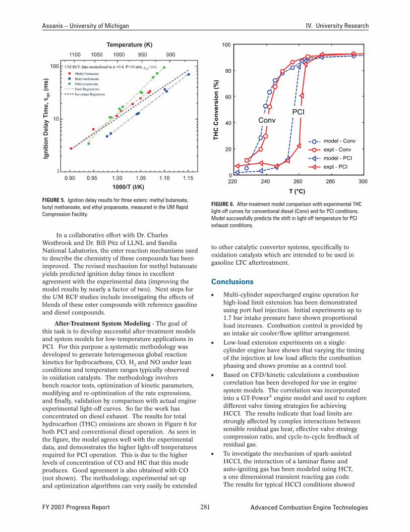
Kinetics and Alternate Fuels - During this year, the investigation of biofuel surrogate autoignition chemistry in the UM Rapid Compression Facility (RCF) has been expanded to include additional C5 esters, beyond work reported last year on methyl butanoate. These studies have quantified the effects of chemical structure on the ignition properties of isomers of methyl butanoate: butyl methanoate and ethyl propanoate. The ignition delay times of these ester/air mixtures were measured at moderate temperatures ~900-1,100 K and pressures (~10 atm) relevant to low-temperature combustion strategies. These data are the first of their kind to quantify the reactivity of these important reference compounds of oxygenated hydrocarbons at conditions important to advanced engine technologies. Figure 5 shows ignition delay results for the three esters along with data for isooctane.
Advanced Combustion Engine Technologies 2�0 FY 2007 Progress Report
Assanis – University of Michigan IV. University Research
FiGure 5. Ignition delay results for three esters: methyl butanoate, butyl methanoate, and ethyl propanoate, measured in the UM Rapid Compression Facility.
In a collaborative effort with Dr. Charles Westbrook and Dr. Bill Pitz of LLNL and Sandia National Labatories, the ester reaction mechanisms used to describe the chemistry of these compounds has been improved. The revised mechanism for methyl butanoate yields predicted ignition delay times in excellent agreement with the experimental data (improving the model results by nearly a factor of two). Next steps for the UM RCF studies include investigating the effects of blends of these ester compounds with reference gasoline and diesel compounds.
After-Treatment System Modeling - The goal of this task is to develop successful after-treatment models and system models for low-temperature applications in PCI. For this purpose a systematic methodology was developed to generate heterogeneous global reaction kinetics for hydrocarbons, CO, H and NO under lean 2
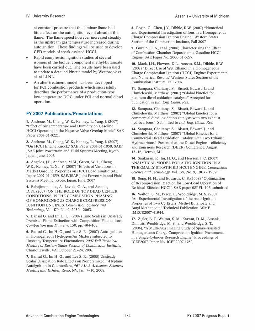
conditions and temperature ranges typically observed in oxidation catalysts. The methodology involves bench reactor tests, optimization of kinetic parameters, modifying and re-optimization of the rate expressions, and finally, validation by comparison with actual engine experimental light-off curves. So far the work has concentrated on diesel exhaust. The results for total hydrocarbon (THC) emissions are shown in Figure 6 for both PCI and conventional diesel operation. As seen in the figure, the model agrees well with the experimental data, and demonstrates the higher light-off temperatures required for PCI operation. This is due to the higher levels of concentration of CO and HC that this mode produces. Good agreement is also obtained with CO (not shown). The methodology, experimental set-up and optimization algorithms can very easily be extended
100
THC
Con
vers
ion
(%)
80
60
40
20
0 220 240 260 280 300
model - Conv expt - Conv model - PCI expt - PCI
Conv PCI
T (°C)
FiGure 6. After-treatment model comparison with experimental THC light-off curves for conventional diesel (Conv) and for PCI conditions. Model successfully predicts the shift in light-off temperature for PCI exhaust conditions.
to other catalytic converter systems, specifically to oxidation catalysts which are intended to be used in gasoline LTC aftertreatment.
conclusions
• Multi-cylinder supercharged engine operation for high-load limit extension has been demonstrated using port fuel injection. Initial experiments up to 1.7 bar intake pressure have shown proportional load increases. Combustion control is provided by an intake air cooler/flow splitter arrangement.
• Low-load extension experiments on a single-cylinder engine have shown that varying the timing of the injection at low load affects the combustion phasing and shows promise as a control tool.
• Based on CFD/kinetic calculations a combustion correlation has been developed for use in engine system models. The correlation was incorporated into a GT-Power® engine model and used to explore different valve timing strategies for achieving HCCI. The results indicate that load limits are strongly affected by complex interactions between sensible residual gas heat, effective valve strategy compression ratio, and cycle-to-cycle feedback of residual gas.
• To investigate the mechanism of spark-assisted HCCI, the interaction of a laminar flame and auto-igniting gas has been modeled using HCT, a one dimensional transient reacting gas code. The results for typical HCCI conditions showed
FY 2007 Progress Report 2�� Advanced Combustion Engine Technologies
IV. University Research Assanis – University of Michigan
at constant pressure that the laminar flame had little effect on the autoignition event ahead of the flame. The flame speed however increased steadily as the upstream gas temperature increased during autoignition. These findings will be used to develop CFD models of spark assisted HCCI.
• Rapid compression ignition studies of several isomers of the biofuel component methyl-butanoate have been carried out. The results have been used to update a detailed kinetic model by Westbrook et al. at LLNL.
• An after-treatment model has been developed for PCI combustion products which successfully describes the performance of a production-type low-temperature DOC under PCI and normal diesel operation.
FY 2007 publications/presentations
1. Andreae, M., Cheng, W. K., Kenney, T., Yang, J. (2007) “Effect of Air Temperature and Humidity on Gasoline HCCI Operating in the Negative-Valve-Overlap Mode,” SAE Paper 2007-01-0221.
2. Andreae, M., Cheng, W. K., Kenney, T., Yang, J. (2007) “On HCCI Engine Knock,” SAE Paper 2007-01-1858, SAE/ JSAE Joint Powertrain and Fluid Systems Meeting, Kyoto, Japan, June, 2007.
3. Angelos, J.P., Andreae, M.M., Green, W.H., Cheng, W.K., Kenney, T., Xu, Y. (2007) “Effects of Variations in Market Gasoline Properties on HCCI Load Limits,” SAE Paper 2007-01-1859, SAE/JSAE Joint Powertrain and Fluid Systems Meeting, Kyoto, Japan, June, 2007.
4. Babajimopoulos, A., Lavoie, G. A., and Assanis, D. N. (2007) ON THE ROLE OF TOP DEAD CENTER CONDITIONS IN THE COMBUSTION PHASING OF HOMOGENEOUS CHARGE COMPRESSION IGNITION ENGINES. Combustion Science and Technology, Vol. 179, No. 9, 2039 - 2063.
5. Bansal G. and Im H. G., (2007) Time Scales in Unsteady Premixed Flame Extinction with Composition Fluctuations, Combustion and Flame, v. 150, pp. 404-408.
6. Bansal G., Im H. G., and Lee S. R., (2007) Auto-ignition in Homogeneous Hydrogen/Air Mixture subjected to Unsteady Temperature Fluctuations, 2007 Fall Technical Meeting of Eastern States Section of Combustion Institute, Charlottesville, VA, October 21–24, 2007.
7. Bansal G., Im H. G., and Lee S. R., (2008) Unsteady Scalar Dissipation Rate Effects on Nonpremixed n-Heptane Autoignition in Counterflow, 46th AIAA Aerospace Sciences Meeting and Exhibit, Reno, NV, Jan. 7–10, 2008.
8. Bogin, G., Chen, J.Y., Dibble, R.W. (2007) “Numerical and Experimental Investigation of Ions in a Homogeneous Charge Compression Ignition Engine,” Western States Section of the Combustion Institute, Fall 2007.
9. Guralp, O. A., et al. (2006) Characterizing the Effect of Combustion Chamber Deposits on a Gasoline HCCI Engine. SAE Paper No. 2006-01-3277.
10. Mack, J.H., Flowers, D.L., Aceves, S.M., Dibble, R.W. (2007) “Direct Use of Wet Ethanol in a Homogeneous Charge Compression Ignition (HCCI) Engine: Experimental and Numerical Results,” Western States Section of the Combustion Institute, Fall 2007.
11. Sampara, Chaitanya S., Bissett, Edward J., and Chmielewski, Matthew (2007) “Global kinetics for platinum diesel oxidation catalysts” Accepted for publication in Ind. Eng. Chem. Res.
12. Sampara, Chaitanya S., Bissett, Edward J., and Chmielewski, Matthew (2007) “Global kinetics for a commercial diesel oxidation catalysts with two exhaust hydrocarbons” Submitted to Ind. Eng. Chem. Res.
13. Sampara, Chaitanya S., Bissett, Edward J., and Chmielewski, Matthew (2007) “Global Kinetics for a Commercial Diesel Oxidation Catalyst with Two Exhaust Hydrocarbons”, Presented at the Diesel Engine – efficiency and Emissions Research (DEER) Conference, August 13–16, Detroit, MI
14. Sankaran, R., Im, H. G., and Hewson, J. C. (2007) ANALYTICAL MODEL FOR AUTO-IGNITION IN A THERMALLY STRATIFIED HCCI ENGINE. Combustion Science and Technology, Vol. 179, No. 9, 1963 - 1989.
15. Song, H. H., and Edwards, C. F.,(2008) “Optimization of Recompression Reaction for Low-Load Operation of Residual-Effected HCCI”, SAE paper 08PFL-406, submitted
16. Walton, S. M., Perez, C., Wooldridge, M. S. (2007) “An Experimental Investigation of the Auto-Ignition Properties of Two C5 Esters: Methyl Butanoate and Butyl Methanoate,” Technical Publication ASME IMECE2007-41944.
17. Zigler, B. T., Walton, S. M., Karwat, D. M., Assanis, Dimitris, Wooldridge, M. S., and Wooldridge, S. T., (2006), “A Multi-Axis Imaging Study of Spark-Assisted Homogeneous Charge Compression Ignition Phenomena in a Single-Cylinder Research Engine” Proceedings of ICEF2007, Paper No. ICEF2007-1762.
Advanced Combustion Engine Technologies 2�2 FY 2007 Progress Report

IV.2 Optimization of Low-Temperature Diesel Combustion
Profs. Rolf Reitz (Primary Contact), Pat Farrell, Dave Foster, Jaal Ghandhi, Scott Sanders, Chris RutlandEngine Research Center (ERC)University of Wisconsin-Madison 1500 Engineering Drive Madison, WI 53706
DOE Technology Development Manager: Gurpreet Singh
NETL Project Manager: Samuel Taylor
Objectives
• Develop methods to optimize and control low-temperature combustion diesel technologies (LTC-D) that offers the potential of nearly eliminating engine nitrogen oxides (NOx) and particulate emissions at reduced cost over traditional methods by controlling pollutant emissions in-cylinder.
• Use single and multi-cylinder engine experiments and detailed modeling to study factors that influence combustion phasing, and particulate, nitric oxide (NO), unburned hydrocarbon (HC) and carbon monoxide (CO) emissions.
• Recommend improved combustion chamber geometries matched to injection sprays.
• Investigate role of fuel-air mixing, fuel characteristics, fuel spray/wall impingement and heat transfer on LTC-D engine control.
• Provide criteria for transition to other engine operation regimes (e.g., standard diesel and low-temperature combustion).
Approach
• Use fully-instrumented engines with prototype fuel injection systems and combustion sensors to map and define HCCI combustion regimes, and apply optimization techniques to discover low emission operation methodologies.
• Develop and apply modeling tools, including multidimensional codes (e.g., KIVA with state-of-the-art turbulent combustion and detailed and reduced chemistry models) to reveal combustion mechanisms.
• Use advanced fuel injection strategies, and manipulation of fuel characteristics to explore approaches to achieve optimal low temperature combustion operation.
• Use fast response diagnostics to formulate transient engine operation strategies during load and speed changes to extend LTC-D engine operating limits.
Accomplishments
• Combustion models and reaction mechanisms have been formulated and applied to analyze and optimize low emissions diesel engine operation.
• In-cylinder optical diagnostics have been developed for H2O species, temperature and turbulence dissipation measurements for use in chemistry and turbulence model validation.
• A two-stage combustion strategy has been formulated and demonstrated with modeling and experiments to achieve 2010 emissions levels with low-temperature combustion operation.
• Engine experiments have revealed that relatively small diesel fuel composition modifications have a significant influence on low-temperature combustion and emissions.
• Advanced large eddy simulation (LES) turbulence models have been applied to reveal more detailed flow information than standard Reynolds averaged Navier Stokes (RANS) models.
• Analysis tools have been developed for development of engine control algorithms, and strategies for thermal and load changes and mode transitions have been explored.
G G G G G
Introduction
This project was initiated in response to a Department of Energy solicitation for research and development on homogeneous charge compression ignition (HCCI) diesel-fueled engines under the “FreedomCAR and Vehicle Technologies Program Solicitation for University Research and Graduate Automotive Technology Education Centers of Excellence.” The program is in response to the fact that the engine industry is currently facing severe emissions mandates. Pollutant emissions from mobile sources are a major source of concern. For example, U.S. Environmental Protection Agency (EPA) mandates require emissions of particulate and NOx from heavy-duty diesel engine exhaust to drop at least 90 percent between 1998 and 2010. Effective analysis of the combustion process is required to guide the selection of technologies for future development since exhaust after-treatment solutions are not currently available that can meet the required emission reduction goals. The goal
FY 2007 Progress Report 283 Advanced Combustion Engine Technologies

IV. University Research Reitz – University of Wisconsin-Madison
of this project is to develop methods to optimize and control LTC-D technologies that offer the potential of nearly eliminating engine NOx and particulate emissions at reduced cost over traditional methods by controlling pollutant emissions in-cylinder. The work is divided into five tasks, featuring experimental and modeling components:
1. Fundamental understanding of LTC-D and advanced model development
2. Experimental investigation of LTC-D combustion control concepts
3. Application of models for optimization of LTC-D combustion and emissions
4. Impact of heat transfer and spray impingement on LTC-D combustion
5. Transient engine control with mixed-mode combustion
Outcomes from the research include providing guidelines to the engine and energy industries for achieving optimal low-temperature combustion operation, and low emissions engine design concepts will be proposed and evaluated.
results
Task 1 - Fundamental Understanding of LTC-D and Advanced Model Development
Homogeneous or partially premixed charge compression ignition combustion is considered to be an attractive alternative to traditional internal combustion engine operation because of its extremely low levels of pollutant emissions. However, since the start-of-combustion timing is controlled by chemistry, kinetic models for diesel combustion are needed for engine analysis. The goal is to reduce available detailed chemistry mechanisms to a manageable size (ideally less than 60 species and 100 reactions) for use in multidimensional simulations. Validation of the mechanism predictions is being done by comparing measured and simulated in-cylinder gas compositions, under LTC conditions. Hyperspectral absorption spectroscopy is being explored for temperature and species concentration measurements. An H2O gas thermometer has been developed that allows temperature measurements to be made in the engine at 3.5 kHz (1 crank angle degree at 600 rev/min) with an unprecedented 0.1% (2 K at 2,000 K) root mean square precision. Sample results are shown in Figure 1. In addition, a new methodology based on Fourier transform infrared spectroscopy has been implemented that will allow ready access to numerous species of interest including H2O, CO2, CO, C2H2, and CH4. Additional information about the diagnostic tools is available at
FiGure 1. Temperature and H2O content measured by hyperspectral H2O absorption spectroscopy for five consecutive engine cycles. The temperature precision exhibits an unprecedented precision of 0.1% (2 K at 2,000 K).
www.erc.wisc.edu (click on “optical diagnostics”), and a patent application has been made [1].
Methodologies for the reduction of kinetic mechanisms are being formulated. As an example, a detailed kinetic reaction mechanism for methyl butanoate (mb) with over 264 species and 1,219 reactions has been reduced and combined with a skeletal mechanism for n-heptane oxidation. The combined mechanism, ERC-bio, contains 55 species and 156 reactions and it has been validated against the detailed mechanism in constant volume simulations. A combined mb/n-heptane mechanism has been applied in KIVA/CHEMKIN engine simulations and compared to biodiesel-fueled engine experiments. The mechanism successfully predicted ignition timing in the simulated engine over a wide range of engine loads.
Task 2 – Experimental Investigation of LTC-D Combustion Control Concepts
An advanced two-stage or dual mode combustion strategy for simultaneous reductions of HC, CO, and NOx has been tested on the ERC’s Caterpillar 3401 SCOTE heavy-duty diesel engine. In this case, a low pressure Bosch gasoline direct injection injector (10 MPa injection pressure) is used together with a high pressure Bosch common rail injector (150 MPa injection pressure), as depicted in Figure 2. The tests were conducted at a high-speed (1,737 rev/min), 57% load operation condition, with a maximum boost pressure of 238 kPa. The optimized pilot low-pressure start of injection (SOI) timing was –145° crank angle (CA) after top dead center (ATDC), and the main high-pressure
Advanced Combustion Engine Technologies 2�� FY 2007 Progress Report

Reitz – University of Wisconsin-Madison IV. University Research
VGS LTC Dual Mode Combustion
160 0.1
Pres
sure
[bar
] 0.075 120
0.05 80
0.025
40 0
0 -0.025 -60 -40 -20 0 20 40 60
C A [ A TD C ]
NA
HR
R
Smooth_Pressure(BAR) NAHRR
FiGure 2. Variable Geometry Spray (VGS) Arrangement with High and Low Pressure Injectors (Left), and Two-Stage Combustion Results (Right).
SOI timing was 15° CA ATDC. Limited by mechanical constraints of the engine, fuel amount tests showed that 70% of the fuel should undergo premixed combustion from the early injection, while the remaining 30% participates in the late injection diffusion burn.
The low-pressure narrow cone angle injector geometry (six-hole 90° cone angle, 168 µm nozzle hole diameter) was found to reduce wall impingement significantly, as well as the associated HC and PM emissions that can result from premixed charge compression ignition (PCCI) fuel preparation with a traditional high pressure diesel injector. The two-stage combustion results produced HC emissions of 1.5 g/kWhr, CO of 12 g/kW-hr, with NOx near the EPA mandate levels of 0.27 g/kW-hr. Late intake valve closure (IVC) of -85° CA ATDC combined with moderate exhaust gas recirculation rates (30%) adequately phased the premixed combustion event while limiting pressure rise rates, as shown in Figure 2. Ongoing experiments are concentrating on optimizing the injector geometries and fuel delivery characteristics to study their effect on spray targeting and PM emissions, and a patent application has been filed that describes the use of a single injector with low and high injection pressures for two-stage combustion [2,3].
The potential of achieving LTC-D operation with wide spray angle direct injection in a high-speed direct injection automotive diesel engine was also explored. In addition to studying spray and mixing parameters, the work explored whether the low-temperature combustion operating range can be expanded with modifications to fuel volatility and cetane number. The work is a collaborative effort between the ERC, GM Research and Development and BP. Tests have included a typical U.S. ultra-low sulfur diesel (ULSD) fuel supplied by BP, a narrow cut U.S. No.2 diesel from ExxonMobil, and
European ECD-1 diesel fuel. A fuel test matrix which varies cetane number, volatility, and total aromatic content has been designed and several fuels have already been blended and delivered by BP. A high cetane number (Fuel E) has been tested at baseline conditions for comparison with the European and U.S. fuels, as shown in Figure 3. As can be seen in the heat release rate plots, differences in cetane number clearly affect ignition delay and combustion phasing, and CO emissions are significantly affected by relatively small differences in fuel composition.
Task 3 – Application of Detailed Models for Optimization of LTC-D Combustion and Emissions
Optimization tools have been used to recommend low-emission engine combustion chamber designs, including non-axi-symmetric piston bowls that could provide better matching with spray plume geometries for enhanced mixing. By coupling genetic algorithm with KIVA-CFD codes, and also utilizing automated grid generation technology, multi-objective optimizations with goals of low emissions and fuel economy have been achieved [4].
In addition, computations have been made using advanced turbulence models. The new KIVA-LES model has been used to study the effect of variable valve actuation on engine-out NOx emissions in the Caterpillar 3401 engine. The simulation results have been compared with experimental measurements [5] and standard KIVA-RANS results. The simulations were based on the experimental data where the original or ‘stock’ IVC timing of 217o ATDC is compared to late IVC timing of 275o ATDC. Combustion is simulated using detailed chemistry for n-heptane with the CHEMKIN solver [6]. NOx emissions are simulated by a reduced
FY 2007 Progress Report 2�� Advanced Combustion Engine Technologies

IV. University Research Reitz – University of Wisconsin-Madison
J/C
A (d
eg)
CO
(g/k
g-Fl
) 250
200
150
100
50
0 -44 -42 -40 -38 -36 -34 -32 -30 -28 -26 -24 -22 -20
Start of Command (deg ATDC) ECD-1 US_ULSD_BP Fuel E
90 HRR comparison at -33 deg ATDC
80
70
60
50
40
30
20
10
0 -30 -25 -20 -15 -10 -5 0 5 10 15 20-10
Crank Angle (deg)
ECD-1 US_ULSD_BP Fuel E
FiGure 3. Measured engine-out CO emissions with European, U.S. and high cetane number (Fuel E=60 cetane number) fuels (top). Fuel effect on heat release rate (bottom).
mechanism with four additional species (N, NO, NO2, N2O) and nine reactions. In the engine experiments, NOx was reduced for the late IVC case. The LES results predicted this trend but did not show as large a reduction as seen in the experimental results. In contrast, the RANS results showed an increase, rather than a decrease in NOx for the late IVC case. Some of the change in NOx is due to different temperature distributions in the cylinder, as seen in Figure 4. In comparing the two IVC cases, the LES results show a smaller region of high temperature gases for the late IVC case while the RANS results show a larger region.
Task 4 – Impact of Heat Transfer and Spray Impingement on LTC-D Combustion
Coupled CFD and thermal analysis codes are being applied to consider heat transfer augmentation by fuel films from spray wall impingement and tested
Temperature(k) LES
Stock IVC Case Late IVC Case
Temperature(k) RANS
FiGure 4. Comparison of LES and RANS In-Cylinder Temperature Contours for Stock and Late IVC Cases at CA = 357° ATDC
against experimental data. Wall films are predicted for early injection cases and this leads to increased NOx emissions due to locally high fuel concentrations. A radiation model based on the discrete ordinates method (DOM) is included in the study.
To validate the soot radiation submodel, comparisons of simulated results to experimental two-color thermometry data from a Sandia optical engine has been conducted. The soot radiation signal between the engine results and the KIVA-CHEMKIN-DOM predictions are being compared. In addition, a new surface grid generator has been developed for use with the wall film model that can be specified independently of the structured KIVA grid. This is needed because unphysical film accumulation has been observed at grid boundaries and this effect is mitigated with the new model. The model is being applied to compute the operation of the Caterpillar SCOTE engine for validation with experimental data. A linkage system has been developed to allow piston surface temperature and heat flux measurements during low temperature diesel combustion.
Task 5 – Transient Engine Control with Mixed-Mode Combustion
The objective of the research is to incorporate and evaluate LTC-D techniques developed as part of the other tasks into the multi-cylinder engine, operating under transient conditions. In addition to the transient operation we are exploring approaches to transition between normal and LTC operation. The engine experiments use the 4-cylinder GM 1.9L engine, and system level tools have been developed for modeling the engine. Single and multi-zone external cylinder models have been implemented in the most recent version of the commercial cycle simulation code GT-Power, together with incorporation of an improved heat transfer
Advanced Combustion Engine Technologies 2�� FY 2007 Progress Report

3
4
5
6
7
Reitz – University of Wisconsin-Madison IV. University Research
10 6. Kong, S.C., Sun, Y. and Reitz, R.D. (2007), “Modeling
9 Diesel Spray Flame Lift-Off, Sooting Tendency and NOX
8 Emissions with Phenomenological Soot Model,” ASME
7 Journal of Gas Turbines and Power, Vol. 129, pp. 245-251,
CA
50 [d
eg A
TDC
]
2007.
IMEP target IMEP actual CA50 target CA50 actual
6
5
IMEP
[bar
]
4 FY 2007 publications/presentations 3 1. UW DOE HCCI Working Group Presentation Meetings:
February and October 2007. 2
1
2 0 0.6 0.8 1 1.2 1.4 1.6 1.8 2 2.2
Time [sec]
FiGure 5. Load transient using 1.9L high-speed direct injection diesel engine model in GT-Power. Combustion phasing (indicated by CA50) is controlled using variable intake valve closing timing.
correlation, and application of transient load control strategies and simulation.
The single zone external cylinder model has been applied to explore early injection diesel HCCI operating conditions. The model allows exploration of engine transients spanning multiple cycles with reasonable computational times. The external cylinder models incorporate sub-models for vaporization, detailed chemistry calculations (CHEMKIN), heat transfer, and species conservation. No mixing effects are considered and the fuel droplets are dispersed as point sources. The research has shown that control of diesel HCCI operation can be accomplished by a range of actuators. Currently, two closed-loop controllers are used to actuate injected fuel quantity and IVC. In this way indicated mean effective pressure (IMEP) and CA50 are regulated to target values, as shown in Figure 5.
references
1. Sanders, S. T.,“Multiplexed-wavelength lasers based on dispersion mode-locking,” UW WARF Patent Application P07171, 5/15/2007.
2. Sun, Y., and Reitz, R.D., “Adaptive Injection Strategy (AIS) for Diesel Engines,” UW WARF Patent Application P07342US, May, 2007.
3. Sun, Y., Kokjohn, S., Weninger, E., and Reitz, R.D., “Adaptive Injection Strategies for Ultra-Low Emissions Diesel Engines,” 13th Diesel Engine Emission Reduction Conference, Detroit, MI, August 24, 2006.
4. Shi, Y and Reitz, R. D., “Assessment of Optimization Methodologies to Study the Effects of Bowl Geometry, Spray Targeting and Swirl Ratio for a Heavy-Duty Diesel Engine Operated at High-load”, SAE 08PFL-126.
5. Nevin, R.M. “PCCI Investigation Using Variable Intake Valve Closing in a Heavy Duty Diesel Engine,” M.S. Thesis, University of Wisconsin–Madison, 2006.
2. Sun, Y., Kokjohn, S., Weninger, E., and Reitz, R.D., “Adaptive Injection Strategies for Ultra-Low Emissions Diesel Engines,” 13th Diesel Engine Emission Reduction Conference, Detroit, MI, August 24, 2006.
3. Abani, N., and Reitz, R.D., “A Model to Predict Spray-tip Penetration for Time-varying Injection Profiles,” Proceedings of ILASS Americas, 20th Annual Conference on Liquid Atomization and Spray Systems, Chicago, IL, May 16, 2007.
4. Sun, Y., and Reitz, R.D., “Modeling Low-Pressure Injections in Diesel HCCI Engines,” Proceedings of ILASS Americas, 20th Annual Conference on Liquid Atomization and Spray Systems, Chicago, IL, May 16, 2007.
5. Park, S.W., Reitz, R.D., Modeling the effect of injector nozzle-hole layout on diesel engine fuel consumption and emissions, Submitted to ASME Journal of Gas Turbines and Power, 2007.
6. Park, S.W., Reitz, R.D., Optimization of fuel/air mixture formation for stoichiometric diesel combustion using a 2spray-angle group-hole nozzle, Submitted Combust. Theory & Model, 2007.
7. Park, S.W., and Reitz, R.D., “Numerical Study on the Low Emission Window of Homogeneous Charge Compression Ignition Diesel Combustion” Combustion Science and Technology, Vol. 179:11, pp. 2279-2307, 2007.
7. Hu, B., Jhavar, R., Singh, S., Reitz, R.D., and Rutland, C.J., “Combustion Modeling of Diesel Combustion with Partially Premixed Conditions,” SAE 2007-01-0163, 2007.
8. Nevin, R.M., Sun, Y., Gonzalez, M.A., and Reitz, R.D., “PCCI Investigation Using Variable Intake Valve Closing in Heavy Duty Diesel Engine,” SAE 2007-01-0903, 2007.
9. Tamagna, D., Ra, Y., and Reitz, R.D., “Multidimensional Simulation of PCCI Combustion Using Gasoline/Dual-fuel Direct Injection and Detailed Chemical Kinetics,” SAE 2007-01-0190, 2007.
10. Singh, S., Wickman, D., Stanton, D., Tan, Z., and Reitz, R.D., “Development and Validation of a hybrid, auto-ignition/flame-propagation model against engine experiments and flame lift off,” SAE 2007-01-0171, 2007.
11. Genzale, C., Wickman, D., and Reitz, R.D., “A Computational Investigation into the Effects of Spray Targeting, Swirl Ratio and Bowl Geometry for Low-Temperature Combustion in a Heavy-Duty Diesel Engine” SAE 2007-01-0119, 2007.
FY 2007 Progress Report 2�7 Advanced Combustion Engine Technologies
IV. University Research Reitz – University of Wisconsin-Madison
12. Hagen, C.L. and Sanders, S.T., “Toward hyperspectral sensing in practical devices: measurements of fuel, H2O, and gas temperature in a metal HCCI engine,” J. Near Infrared Spectroscopy, 2007.
13. Kraetschmer, T., Lan, C., and Sanders, S.T., “Custom multiwavelength frequency-division-multiplexed laser based on dispersion mode locking” IEEE Photo. Tech. Letters, in press, 2007.
14. Kranendonk, L.A., Caswell ,A.W. and Sanders, S.T.,”Robust Method for Calculating Temperature, Pressure and Absorber Mole Fraction from Broadband Spectra,” Appl. Opt., 2007.
15. Hagen, C.L. and Sanders, S.T., “Investigation of Multi-species (H2O2 and H2O) Sensing and Thermometry in an HCCI Engine by Wavelength-Agile Absorption Spectroscopy,” Measurement Sci. Tech., in press, 2007.
16. Opat, R., et al., “Investigation of Mixing and Temperature Effects on HC/CO Emissions for Highly Dilute Low Temperature Combustion in a Light Duty Diesel Engine,” SAE paper 2007-01-0193, 2007.
Advanced Combustion Engine Technologies 2�� FY 2007 Progress Report

IV.3 Low-Temperature Combustion with Thermo-Chemical Recuperation to Maximize In-Use Engine Efficiency
Nigel N. Clark (Primary Contact), Francisco Posada, Clint Bedick Center for Alternative Fuels, Engines & Emissions (CAFEE) Department of Mechanical and Aerospace Engineering West Virginia University PO Box 6106 Morgantown, WV 26506-6106
DOE Technology Development Manager: Gurpreet Singh
NETL Project Manager: Aaron Yocum
Subcontractors: • Gas Technology Institute (GTI), Des Plaines, IL
(John Pratapas, Lead Investigator) • Atkinson LLC, Morgantown, WV
(Christopher Atkinson, Lead Investigator)
Objectives
• To substantially improve (10% fuel use reduction) the efficiency of compression ignition engines for both light-duty and heavy-duty use while meeting or exceeding the ultra-low NOx emission requirements for the 2010 engine model year.
• To utilize alternative combustion modes, coupled with thermo-chemical reforming of fuel to recover exhaust waste heat, with an optimization of the mean effective pressure versus displacement tradeoff.
• To develop technology under this project that will enable engine prototype development by 2012.
Accomplishments
• Simple models for low-temperature combustion (LTC) and diesel engines were implemented to obtain the pressure and temperature data required for the evaluation of efficiency for each type of engine.
• Values of energy losses in the LTC engine were compared with energy losses of a diesel engine with half the displacement of the LTC engine. Energy losses assessed in this model include friction, auxiliaries and heat transfer.
• A model to evaluate the total cooling burden was developed and to assess the impact of the energy
losses in the fan energy requirements, which is also powered by the engine.
• Model results showed that the total cooling burden on a LTC engine with higher displacement and lower power density was 15.6% lower than the diesel engine for the same amount of energy addition in the case of high load (43.57 mg fuel/cycle).
• A steam/fuel reforming bench was designed, built and tested by GTI. n-Heptane was employed as a surrogate fuel, in order to analyze the impact on H2
and CO production due to changes in reforming temperature, fuel flow rate, steam/n-heptane mole ratio and heat addition to the reformer.
• Laboratory results, at a steam/carbon mole ratio less than 2:1, confirm that reforming reactions, in the temperature range of 550 K to 650 K, can produce 10-30% hydrogen (by volume, wet) in the product stream.
Future Directions
The project, based on the original objectives, included three phases, which included experimental verification of the “two fuels” approach to LTC, which provided for integration of a reformer with an engine, and which provided for system controls development. Although Phase 1 results suggest that the LTC/thermochemical recuperation (TCR) combination is attractive, DOE funding constraints have dictated a more austere project, directed at (1) modeling to demonstrate the “two fuels” approach benefits in managing in-cylinder combustion, (2) determination of the optimal use of pre-and post-turbocharger heat from a system perspective, (3) design of the integrated heat exchanger and reformer, and (4) addressing the complete system design and control through modeling.
G G G G G
introduction
LTC is a broad concept that involves combustion systems where the in-cylinder temperature is kept below temperatures that promote substantial NOx and soot formation [1]. Although LTC combustion has emerged as an alternative to spark ignition and compression ignition direct injection (CIDI) combustion due to decrease in exhaust emissions and improvement in fuel economy, it is difficult to maintain LTC combustion over the entire operational engine load range. The control over ignition timing and the rate of heat release are the
FY 2007 Progress Report 2�� Advanced Combustion Engine Technologies

IV. University Research Clark – West Virginia University
primary parameters affected by the nature of this kind of combustion process. The control of LTC is the most challenging issue for commercial applications of LTC.
In general, two directions have been investigated to extend the operational range of LTC and provide the required control: modifying air/fuel mixture properties and modifying engine operation and design parameters [2]. The final purpose of each of these strategies is to modify the composition and/or temperature of the in-cylinder charge. The research presented in this report examines the feasibility of using TCR technologies to produce the secondary fuel stream in an on-board reforming reactor as a reformed product of the primary fuel in the tank. In parallel, an optimization of the mean effective pressure versus displacement tradeoff was studied to address the need for broad operating range in LTC operation.
Approach
It is proposed in this research to accept the mean effective pressure (MEP) values at which LTC has been shown to work successfully, and increasing cylinder displacement to reach the typical power output of a CIDI engine. Initial modeling was performed to determine the differences in MEP, heat loss, friction and auxiliary losses, and efficiency between a diesel CIDI engine and a LTC engine. The diesel CIDI cylinder basic geometry was taken from a Cummins B-series 5.9 liter engine and the LTC cylinder was modeled with double the displacement of the CIDI while keeping the same compression ratio. The results from LTC modeling were applied to TCR experimental results to determine the feasibility of combining the two systems to extend the operational range of LTC. Throughout initial modeling and experimental research, n-heptane was used as an alternative to diesel fuel, but future research and a final LTC/TCR system would implement diesel. This report presents results from LTC modeling and TCR experimental work in order to show that the overall system is feasible and has the potential to increase engine efficiency and extend the actual operational range of LTC engines.
results
Comparison Between Diesel Engine and LTC Engine: Heat Transfer, Friction and Auxiliaries Losses
The authors have argued that the lower power density of LTC might be accepted by increasing displacement without altering the engine lower end design. A comparison was considered for an LTC engine with twice the displacement of the diesel engine,
modeled using a 0.98 liter displacement for one cylinder and the LTC engine was modeled at double (1.96 liter) this displacement. The bore and stroke were varied in two different ways to represent a 1.96 liter displacement engine. In the first case the face area of the piston was doubled and the stroke remained unchanged. In the second case the volume was doubled but the aspect ratio of the cylinder was kept the same (bore/stroke=1).
Typical pressure and temperature curves for the LTC and CIDI engines are shown in Figure 1. The peak pressure values obtained in the LTC model were higher than those obtained for the CIDI model, although the general trend showed a lower pressure for the LTC engine as should be expected from a higher cylinder face area. Intake temperatures for LTC were higher than those used for CIDI simulation due to auto-ignition requirements of the LTC case. It should be noticed that although the peak temperature in the LTC case was similar to the maximum temperature obtained in the CIDI case, the LTC peak temperature value was overshot with respect to typical experimental homogeneous charge compression ignition data and the general trend showed a lower cylinder temperature for the LTC case as expected from higher expansion ratios.
Heat Transfer Losses
The cumulative heat loss was compared for two different engines, a LTC engine and a CIDI engine, operating at the same amount of fuel per cycle. Two different load cases were applied: a low load of 21.89 mg of fuel per cycle and a high load of 43.57 mg of fuel per cycle. Figures 2a and 2b show the cumulative heat loss in both cases. At low load the total amount of heat loss was slightly higher (1.2%) for the CIDI engine because
but approximately half of the indicated mean effective pressure (IMEP). In this way, the output of the engines FiGure 1. Pressure and Temperature Trends for LTC and CIDI at the could be similar. Therefore, the CIDI engine was Same Amount of Fuel Per Cycle (43.57 mg)
Advanced Combustion Engine Technologies 2�0 FY 2007 Progress Report
Clark – West Virginia University IV. University Research
(a) (b)
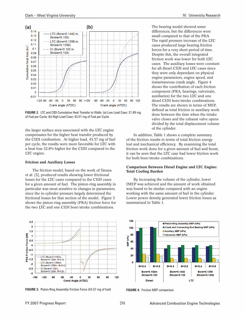
FiGure 2. LTC and CIDI Cumulative Heat Transfer to Walls: (a) Low Load Case: 21.89 mg of Fuel per Cycle; (b) High Load Case: 43.57 mg of Fuel per Cycle
the larger surface area associated with the LTC engine compensates for the higher heat transfer produced by the CIDI combustion. At higher load, 43.57 mg of fuel per cycle, the results were more favorable for LTC with a heat loss 32.8% higher for the CIDI compared to the LTC engine.
Friction and Auxiliary Losses
The friction model, based on the work of Taraza et al. [3], produced results showing lower frictional losses for the LTC cases compared to the CIDI cases for a given amount of fuel. The piston-ring assembly in particular was most sensitive to changes in parameters, since the in-cylinder pressure largely determined the frictional losses for that section of the model. Figure 3 shows the piston-ring assembly (PRA) friction force for the two LTC and one CIDI bore/stroke combinations.
The bearing model showed some differences, but the differences were small compared to that of the PRA. The rapid pressure increase of the LTC cases produced large bearing friction forces for a very short period of time. Despite this, the overall integrated friction work was lower for both LTC cases. The auxiliary losses were constant for all diesel CIDI and LTC cases since they were only dependant on physical engine parameters, engine speed, and instantaneous crank angle. Figure 4 shows the contribution of each friction component (PRA, bearings, valvetrain, auxiliaries) for the two LTC and one diesel CIDI bore/stroke combinations. The results are shown in terms of MEP, defined as total friction or auxiliary work done between the time when the intake valve closes and the exhaust valve opens divided by the total displacement volume of the cylinder.
In addition, Table 1 shows a complete summary of the friction results in terms of total friction energy lost and mechanical efficiency. By examining the total friction work done for a given amount of fuel and boost, it can be seen that the LTC case had lower friction work for both bore/stroke combinations.
Comparison Between Diesel Engine and LTC Engine: Total Cooling Burden
By increasing the volume of the cylinder, lower IMEP was achieved and the amount of work obtained was found to be similar compared with an engine working with the same amount of fuel in the cylinder. Lower power density generated lower friction losses as summarized in Table 1.
FiGure 3. Piston-Ring Assembly Friction Force (43.57 mg of fuel) FiGure 4. Friction MEP comparison
FY 2007 Progress Report 2�� Advanced Combustion Engine Technologies

IV. University Research Clark – West Virginia University
Table 1. Summary of Conditions, Friction Losses, Heat Transfer and Work During One Cycle
A comparative evaluation of the fan load showed that although the absolute values were not representative, the relative values were highly favorable for the LTC engine. At light loads the benefit was 14.3% and at higher loads the benefit was more substantial, reaching 44.23% when compared to the CIDI results. The total cooling burden values obtained for LTC were approximately the same at lower loads compared with the CIDI engine. At higher loads the benefit was more noticeable, with 15.5% lower cooling burden for the LTC compared to the CIDI engine. The amount of work produced per cycle showed a slightly benefit in the case of the LTC engine (double displacement) when it was compared at the same amount of fuel per cycle, which increases its thermal and mechanical efficiency respect to the CIDI engine. The calculated efficiency benefit of the LTC was more evident at higher loads where the actual experimental results are limited by knock phenomena.
n-Heptane Steam Reforming Experimental Results
A TCR system was developed by GTI for implementation on a LTC engine. Initial modeling of n-heptane steam reforming was performed by GTI using equilibrium reactions and HYSYS software. Validation of modeling results was performed based on typical exhaust flow and temperatures of the LTC engine. The reformer, presented in Figure 5, was tested in order to estimate the reforming rate and process efficiency for non-catalytic and catalyzed reforming.
Experimental data, including reformer gas composition and hydrogen yield, was produced for a range of reformer temperatures. In addition, a comparison to modeling results was performed to validate the model. Figure 6 shows the main components of the reformed fuel composition (measured wet) for a steam/carbon molar ratio of 2:1 with catalyst. There was up to 45% H2 and 18% CO (by volume,
FiGure 5. Experimental Setup for n-Heptane/Steam Reforming
FiGure 6. Reformed Gas Composition with Catalyst (Steam/Carbon Molar Ratio 2:1)
wet) in the reformed fuel at a relatively low reforming temperature (≈700 K)
To characterize the process efficiency for hydrogen production, hydrogen yield was estimated as the weight ratio of hydrogen produced to n-heptane fed into the reformer. The hydrogen yield varied from zero to near 20% almost linearly with the temperature varying from 570 K to 700 K. Inferior values of hydrogen yield were obtained without catalyst even when the reforming temperature was increased up to at 850 K. Process
Advanced Combustion Engine Technologies 2�2 FY 2007 Progress Report

Clark – West Virginia University IV. University Research
completeness was used as a parameter to describe the reforming process, defined by actual conversion amount as a percentage of theoretical equilibrium conversion amounts. The experimental reformer could provide close to 100% process completeness at 690 K for catalytic reforming and 860 K for non-catalytic reforming. Approximately the same process completeness was achieved for catalytic and non-catalytic reforming at temperatures 550 K-650 K, suggesting that those temperatures are low for the catalyst.
Synergy Between LTC and TCR
The well known sensitivity of the LTC mode to temperature and charge composition has been proved with a simple two-step chemical kinetics model. The strong influence of intake temperature, equivalence ratio and exhaust gas recirculation on the ignition event shows that the LTC engine requires additional sources of control to obtain the desired benefits regarding emissions and thermal efficiency of this technology. Based on the results obtained from the LTC model, values of exhaust temperature were calculated to examine the operational range of the TCR system. The resulting values of exhaust temperatures based on a model of adiabatic expansion of ideal gas mixture (at 100 kPa) match the operational range where the catalyst is more effective and where the process completeness is higher than 60%. Moreover, the LTC mode has demonstrated good behavior in the low power requirement, range where TCR would not be required and where the available reforming temperature from exhaust gases was low and therefore low reforming process completeness was obtained. It should be noticed that the temperature of the gases obtained from the adiabatic expansion model may be higher than those obtained from a real prototype where heat transfer losses are involved in the process, but the exhaust area can be configured to minimize heat loss if the intent is to optimize waste heat recovery.
conclusions
Modeling results demonstrated that the LTC engine with double the displacement of the CIDI engine shows a higher overall efficiency, with lower cooling burden and friction losses for a given amount of fuel per cycle when compared to CIDI diesel combustion.
1. Values of heat loss at different load conditions were evaluated for both the CIDI engine and the LTC engine and the results showed that the amount of heat transfer was significant at higher load. In this case the heat transfer at 43.57 mg of fuel per cycle was 32.8% higher for the CIDI engine than for the LTC engine.
2. Slight differences were found in the final value of friction losses for both the CIDI engine and the LTC engine operating at the same amount of energy input.
3. The total balance of cooling burden, including heat transfer and frictional losses was favorable for the proposed LTC engine at double displacement when it was compared to the diesel engine under the same energy input base.
4. Mechanical efficiencies at low load were similar between the CIDI and the LTC engine. At high load the calculated difference is 4.4% higher for the LTC engine.
Experimental results showed that TCR could produce a hydrogen-rich reformer fuel at various exhaust temperatures by steam reforming of liquid n-heptane.
1. For steam/n-heptane mole ratio of 15, complete n-heptane conversion was expected for temperatures slightly above 700 K.
2. Steam/n-heptane ratio could be optimized in order to maximize n-heptane conversion.
3. Appropriate catalysts should be selected for higher n-heptane conversion at low temperature.
4. Additionally, LTC modeling has proven that the LTC exhaust temperature was within the range of significant hydrogen production.
references
1. Kook S., Bae C., Miles P.C., Choi D., Pickett L.M., “The Influence of Charge Dilution and Injection Timing on Low-Temperature Diesel Combustion and Emissions,” SAE Paper 2005-01-3837, 2005.
2. Milovanovic N., and Chen R.., “A review of experimental and simulation studies on controlled auto-ignition combustion,” SAE Paper 2001-01-1890, 2001.
3. Taraza, D., Henein, N., Bryzik, W., “Friction Losses in Multi-Cylinder Diesel Engines,” SAE Paper 2000-01-0921, 2000.
FY 2007 publications and presentations
1. Posada F., Bedick C., Clark N., Kozlov A., Linck M., Boulanov D., Pratapas J., “Low Temperat ure Combustion with Thermo-chemical Recuperation,” SAE Paper 2007-014074, 2007.
2. Diesel Engine-Efficiency and Emissions Research (DEER) conference poster presentation: Enabling Low Temperature Combustion Trough Thermo Chemical Recuperation. Detroit, MI, 2007.
FY 2007 Progress Report 2�� Advanced Combustion Engine Technologies

IV.4 Kinetic and Performance Studies of the Regeneration Phase of Model Pt/Ba/Rh NOx Traps for Design and Optimization
Michael P. Harold (Primary Contact) and Vemuri Balakotaiah University of Houston Department of Chemical and Biomolecular Engineering S222 Engineering Building 1 Houston, TX 77204-4004
DOE Technology Development Manager: Ken Howden
NETL Project Manager: Aaron Yocum
Objectives
• Carry out studies of regeneration kinetics on lean NOx trap (LNT) catalysts.
• Evaluate and compare the effect of different reductants on LNT performance.
• Incorporate the kinetics findings and develop and analyze a first-principles based predictive LNT model for design and optimization.
• Test the new LNT designs in a heavy-duty diesel vehicle dynamometer facility.
Accomplishments
• Carried out a comprehensive experimental study of the steady-state behavior of the NO/H and2
NO/H2/O2 reaction systems on model Pt and Pt/Ba monolith catalysts. Integral conversion and selectivity data were obtained over a range of temperatures, feed compositions, and catalyst loadings (Pt, BaO). The analytical system was upgraded to include a mass spectrometer, enabling the measurement of N and H in addition to the2 2
remaining species measured by Fourier transform infrared (FTIR) spectroscopy. The kinetics of several underlying chemistries was also studied, including NO reduction by ammonia, ammonia oxidation by O , and ammonia decomposition.2
These data are being used to develop a predictive microkinetic model. The anaerobic data will appear in a combined experimental-modeling paper in Applied Catalysis B. Environmental. The aerobic data are the basis for a second publication in the same journal.
• Carried out a comprehensive study of the performance of model Pt/Ba catalysts under simulated cycling with H2 as the reductant. Detailed performance data on instantaneous and cycle-
averaged product distributions were obtained. Several key findings were obtained of the transient product distribution. A series of varied-length experiments elucidated the role of ammonia as both a byproduct and reductant. A manuscript will be submitted to Applied Catalysis on this work.
• Carried out transient kinetics studies of model Pt catalysts with the temporal analysis of products (TAP) reactor. Sequential pulsing of NO and NO/ H2 pump/probe experiments on Pt catalysts revealed a complex dependence on temperature, pulse timing, and NO/H2 feed ratio. The data helped to elucidate the mechanistic sequence describing the production of N2, N2O, and NH3.
• Developed a mathematical model to simulate the NO decomposition and NO/H2 reaction system in the TAP reactor. An algorithm has been developed to estimate kinetic parameters using this model.
• Developed a predictive microkinetic model for the NO/H2 on Pt reaction system. A monolith reactor model incorporating the microkinetic model and transport processes predicted all of the main features of steady-state data over a wide range of temperature and feed composition.
Future Directions
During the third year of the project we will focus our efforts on the following activities (with more detailed plans to follow):
• Conduct bench-scale experiments on the role of Rh and CeO2 on the performance of the LNT.
• Focus on the effect of Pt/Ba interfacial coupling through bench-scale and TAP reactor experiments that quantify the effect of Pt/Ba interfacial perimeter on the activity and product distribution.
• Carry out selected TAP experiments using monolith catalysts, enabling a direct comparison of bench-scale and TAP data.
• Estimate unknown kinetic parameters through simulation of TAP experiments with monolith catalysts.
• Extend the LNT modeling through continued upgrades of the microkinetics. Focus efforts on the simulation of transient data.
• Utilize the LNT model with the microkinetics to investigate different NOx trap operating strategies and designs.
G G G G G
Advanced Combustion Engine Technologies 2�� FY 2007 Progress Report

Harold – University of Houston IV. University Research
introduction
During the second year of the project we have made very good progress in integrating experimental and theoretical efforts spanning bench-scale reactor studies, TAP reactor studies, microkinetic modeling, and reactor modeling. Our efforts have focused on mechanistic studies in TAP reactor, bench-scale studies of NOx trap using synthetic feeds and model NOx storage and reduction (NSR) catalysts, and development of first-principles NOx trap reactor model comprising a microkinetic description of the storage and reduction chemistry. Our activities involved elucidating steady-state and transient studies of several underlying chemistries in the bench-scale and TAP reactors, in formulating a predictive microkinetic model, and incorporating the chemistry knowledge into monolith reactor models. The experiments to date have considered Pt, and Pt/Ba catalysts using H2
as the reductant. A family of model catalysts has been provided to us during the past year by BASF Catalysts LLC; these contain additional components including Rh and CeO2.
Approach
We utilize a combination of experimental and theoretical tools to advance the LNT technology. Fundamental kinetics studies are carried out of model Pt/Rh/Ba NSR powder and monolith catalysts with reductants H and CO in the TAP reactor. The TAP 2
reactor provides transient data under well-characterized conditions, enabling both the identification of key reaction pathways and estimation of the corresponding kinetic parameters. The performance of model NSR monolith catalysts are evaluated in a bench-scale NOx trap using synthetic exhaust, with attention placed on the effect of the pulse timing and composition on the instantaneous and cycle-averaged product distributions. From these measurements we formulate a mechanistic-based microkinetic model that incorporates a detailed understanding of the chemistry, and incorporate the kinetic model into a LNT model. The NOx trap model is used to determine its ability to simulate bench-scale data and ultimately to evaluate alternative LNT designs and operating strategies.
results
During the second year we continued mechanistic studies of NO uptake (storage) and NO reduction by H2
on Pt/Al2O3 and Pt/Ba/Al2O3 powder catalysts (provided by BASF Catalysts LLC). This work involves both TAP reactor experimental and modeling studies and is the doctoral thesis of one of the graduate students. Up to this point in the project we have primarily used the TAP experiments to elucidate certain features of
the NO/H2 transient uptake and catalytic chemistry. NO pulsing experiments provide information about the adsorption and decomposition while NO/H2 pump-probe experiments provide detailed information about the reaction pathways to products N2, N2O, and NH3. The principle effort involved the completion of NO/H2
pump-probe experiments on the Pt and Pt/Ba catalysts over a range of temperature (150-350oC). This has been important for guiding our efforts in elucidating bench-scale reactor performance data and for constructing a microkinetic model.
We made considerable progress in forming a comprehensive database for steady-state and cyclic bench-scale monolith reactor experiments. This task is conducted by a doctoral student who is partially supported by DOE. We utilize a monolith reactor system comprising a simulated exhaust feed system, flow through reactor, and dedicated analytical system. During the last quarter we added a quadrupole mass spectrometer to the system to provide critical capability for measuring non-infrared active species including N2
and H2. Up to this point, both of these species were estimated by overall N and H balances, respectively. Coupled with the FTIR, this gives us the ability to conduct more detailed experiments.
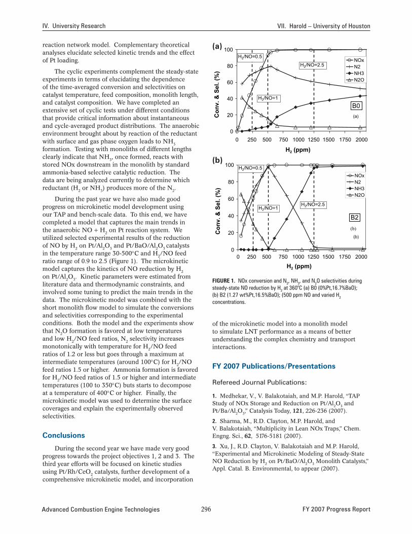
Comprehensive steady-state experiments on the selective catalytic reduction of NO on a series of Pt, Pt/BaO, and BaO monolithic catalysts were carried out to evaluate the light-off, NOx conversion and product distribution features as a function of the feed composition, temperature and catalyst composition. The reaction between NO and H2 produces a mixture containing N2O, NH3, and N2, the composition of which is a function of the catalyst temperature and NO/H2
ratio in the feed. NO strongly inhibits the reaction at low temperatures. NOx conversions were found to be complete at space velocities below 90,000 hr-1 and above 100oC for Pt loadings exceeding 1.27%. Particular attention focused on the production and consumption of ammonia, a problematic byproduct during NSR. NH3
is a key product in O2 deficient conditions typical of the rich pulse in NSR, while N2 and N2O are the main products at higher O2 concentrations (lean conditions). NH3 oxidation ignites on Pt catalysts at 180-200oC; in the ignited state a mixture of N2, NO, NO2 and N2O is produced, the composition of which is sensitive to the NH3/O2 feed ratio and temperature. The decomposition of NH3 is observed above 360oC and is inhibited by small amounts of H2. Experiments involving a feed containing H2, NH3, and NO reveal that H2 is a much more effective reductant. A comparison of the three catalysts reveals similar steady-state behavior between the Pt and Pt/BaO catalysts. The BaO catalyst exhibited a non-negligible but lower activity and a different product distribution than the Pt and Pt/BaO catalysts. The data are interpreted with a phenomenological
FY 2007 Progress Report 2�� Advanced Combustion Engine Technologies
IV. University Research VII. Harold – University of Houston
reaction network model. Complementary theoretical (a) 100analyses elucidate selected kinetic trends and the effect of Pt loading.
80 NOx N2 NH3 N2O
H2/NO=2.5
H2/NO=0.5
B0 H2/NO=1
(a)
The cyclic experiments complement the steady-state experiments in terms of elucidating the dependence of the time-averaged conversion and selectivities on catalyst temperature, feed composition, monolith length, and catalyst composition. We have completed an extensive set of cyclic tests under different conditions that provide critical information about instantaneous and cycle-averaged product distributions. The anaerobic
Con
v. &
Sel
. (%
)
60
40
20
environment brought about by reaction of the reductant 0
with surface and gas phase oxygen leads to NH 0 250 500 750 1000 1250 1500 1750 20003
formation. Testing with monoliths of different lengths H2 (ppm) clearly indicate that NH3, once formed, reacts with (b)stored NOx downstream in the monolith by standard 100 ammonia-based selective catalytic reduction. The data are being analyzed currently to determine which 80
NOx N2 NH3 N2O
H2/NO=2.5
H2/NO=0.5
B2 H2/NO=1
(b)
(b)
reductant (H2 or NH3) produces more of the N2.
During the past year we have also made good progress on microkinetic model development using our TAP and bench-scale data. To this end, we have completed a model that captures the main trends in the anaerobic NO + H2 on Pt reaction system. We C
onv.
& S
el. (
%)
60
40
20 utilized selected experimental results of the reduction of NO by H2 on Pt/Al2O3 and Pt/BaO/Al2O3 catalysts in the temperature range 30-500°C and H2/NO feed ratio range of 0.9 to 2.5 (Figure 1). The microkinetic model captures the kinetics of NO reduction by H2
on Pt/Al2O3. Kinetic parameters were estimated from literature data and thermodynamic constraints, and involved some tuning to predict the main trends in the data. The microkinetic model was combined with the short monolith flow model to simulate the conversions and selectivities corresponding to the experimental conditions. Both the model and the experiments show that N2O formation is favored at low temperatures and low H2/NO feed ratios, N2 selectivity increases monotonically with temperature for H2/NO feed ratios of 1.2 or less but goes through a maximum at intermediate temperatures (around 100°C) for H2/NO feed ratios 1.5 or higher. Ammonia formation is favored for H2/NO feed ratios of 1.5 or higher and intermediate temperatures (100 to 350°C) buts starts to decompose at a temperature of 400°C or higher. Finally, the microkinetic model was used to determine the surface coverages and explain the experimentally observed selectivities.
conclusions
During the second year we have made very good progress towards the project objectives 1, 2 and 3. The third year efforts will be focused on kinetic studies using Pt/Rh/CeO2 catalysts, further development of a comprehensive microkinetic model, and incorporation
0 0 250 500 750 1000 1250 1500 1750 2000
H2 (ppm)
FiGure 1. NOx conversion and N2, NH3, and N2O selectivities during steady-state NO reduction by H2 at 360oC (a) B0 (0%Pt,16.7%BaO); (b) B2 (1.27 wt%Pt,16.5%BaO); (500 ppm NO and varied H2
concentrations.
of the microkinetic model into a monolith model to simulate LNT performance as a means of better understanding the complex chemistry and transport interactions.
FY 2007 publications/presentations
Refereed Journal Publications:
1. Medhekar, V., V. Balakotaiah, and M.P. Harold, “TAP Study of NOx Storage and Reduction on Pt/Al2O3 and Pt/Ba/Al2O3,” Catalysis Today, 121, 226-236 (2007).
2. Sharma, M., R.D. Clayton, M.P. Harold, and V. Balakotaiah, “Multiplicity in Lean NOx Traps,” Chem. Engng. Sci., 62, 5176-5181 (2007).
3. Xu, J., R.D. Clayton, V. Balakotaiah and M.P. Harold, “Experimental and Microkinetic Modeling of Steady-State NO Reduction by H2 on Pt/BaO/Al2O3 Monolith Catalysts,” Appl. Catal. B. Environmental, to appear (2007).
Advanced Combustion Engine Technologies 2�� FY 2007 Progress Report

Harold – University of Houston IV. University Research
4. Clayton, R.D., M.P. Harold, and V. Balakotaiah, “Selective Catalytic Reduction of NO by H2 in O2 on Pt/BaO/Al2O3 Monolith NOx Storage Catalysts,” Appl. Catal. B. Environmental, accepted with minor revisions (2007).
Conference Presentations: (during second year)
1. “Modeling and Experimental TAP Studies on the Kinetics of NOx Storage and Reduction over Pt/Al2O3 and Pt/BaO/Al2O3 Catalysts,” presented at the AIChE National Meeting, San Francisco, CA, 11/06 (M. Harold,V. Medhekar and V. Balakotaiah).
2. “Steady State and Dynamic Studies of NOx Storage and Reduction with H2 on Pt/BaO/Al2O3 Monoliths,” presented at the AIChE National Meeting, San Francisco, CA, 11/06 (R. Clayton, M. Harold, and V. Balakotaiah).
3. “Modeling of NOx Storage and Reduction in Catalytic Monolith Reactors,” presented at the AIChE National Meeting, San Francisco, CA, 11/06 (J. Xu, M. Harold, and V. Balakotaiah).
4. “Ammonia Formation During Steady-State and Cyclic Operation of the NOx Trap with H2 as the Reductant,” Clayton, R., V. Balakotaiah, and M. Harold, NASCRE 2, Houston, TX, 2/07 (R. Clayton, M. Harold, and V. Balakotaiah).
5. “Determination of the Microkinetics of NOx Storage and Reduction on Pt/BaO/Al2O3 Catalysts Using TAP,” NASCRE 2, Houston, TX, 2/07 (A. Kumar, V. Medhekar, V. Balakotaiah, and M. Harold).
6. “Ammonia and Nitrous Oxide Formation during NOx Storage and Reduction on Pt/Ba Monolith Catalysts,” poster presented at North American Catalysis Society Conference, Houston, Texas, 6/07 (R.Clayton, M. Harold, and V. Balakotaiah).
7. “Microkinetic Model Development of NOx Storage and Reduction over Pt/BaO/Al2O3 Catalyst using Temporal Analysis of Product Reactor,” poster presented at North American Catalysis Society Conference, Houston, Texas, 6/07 (A. Kumar, V. Medhekar, M. Harold and V. Balakotaiah).
FY 2007 Progress Report 2�7 Advanced Combustion Engine Technologies

IV.5 Investigation of Aging Mechanisms in Lean NOx Traps
Mark Crocker (Primary Contact), Yaying Ji, Vence Easterling University of Kentucky Center for Applied Energy Research 2540 Research Park Drive Lexington, KY 40511
DOE Technology Development Manager: Ken Howden
NETL Project Manager: Aaron Yocum
Subcontractor:Oak Ridge National Laboratory, Oak Ridge, TN
Partners: • Ford Motor Co., Dearborn, MI (Bob McCabe) • Umicore Autocat USA, Inc., Auburn Hills, MI
(Owen Bailey)
Objectives
• Examine the effect of washcoat composition on lean NOx trap (LNT) catalyst aging characteristics. To this end, prepare model Pt/Rh/CeO2(-ZrO2)/BaO/ Al2O3 catalysts with systematic variation of the main component concentrations.
• Study the physical and chemical properties of the model catalysts in the fresh state and after aging.
• Investigate transient phenomena in the fresh and aged catalysts during lean-rich cycling using spatially resolved capillary inlet mass spectrometry (SpaciMS).
• Investigate the kinetics and mechanism of desulfation in fresh and aged catalysts using chemical ionization mass spectrometry for the simultaneous analysis of evolved sulfur species.
• Correlate evolution of catalyst microstructure to NOx storage and reduction characteristics.
Accomplishments
• Bench reactor tests were performed on a series of model monolith catalysts, in which the concentrations of the four main active components, Pt, Rh, CeO2 (or CeO2-ZrO2) and BaO were systematically varied. From the resulting data, catalyst activity-composition (and in some cases selectivity-composition) correlations were derived.
• An automated catalyst aging cycle has been implemented for the accelerated aging of model monolithic catalysts.
• SpaciMS was applied to the study of transient catalyst response in the model monolithic catalysts. Under lean-rich cycling conditions, ceria was found to exert significant effects on the intra-catalyst chemistry, as demonstrated by the analysis of rich phase intra-catalyst H2 concentration profiles.
• Desulfation experiments were performed on the model monolith LNTs, revealing a dependence of desulfation efficiency on catalyst ceria content and precious metal loading.
Future Directions
• Complete accelerated aging of model monolithic catalysts (repeated sulfation/desulfation cycles).
• Characterize aged catalysts using standard physicochemical techniques, in tandem with bench reactor tests, in order to correlate catalyst aging characteristics with washcoat composition.
• Perform in situ diffuse reflectance infrared fourier transform spectroscopy (DRIFTS) and on-line mass spectrometry measurements on model powder catalysts in order to gain improved insights into the chemistry of catalyst desulfation.
G G G G G
introduction
LNTs represent a promising technology for the abatement of NOx under lean conditions. Although LNTs are starting to find commercial application, the issue of catalyst durability remains problematic. LNT susceptibility to sulfur poisoning is the single most important factor determining effective catalyst lifetime. The NOx storage element of the catalyst has a greater affinity for SO3 than it does for NO2, and the resulting sulfate is more stable than the stored nitrate. Although this sulfate can be removed from the catalyst by means of high temperature treatment under rich conditions, the required conditions give rise to deactivation mechanisms such as precious metal sintering, total surface area loss, and solid state reactions between the various oxides present. The principle objective of this project is to improve understanding of the mechanisms of LNT aging, and to understand the effect of washcoat composition on catalyst aging characteristics.
Approach
The approach utilized makes use of detailed characterization of model catalysts prior to and after aging, in tandem with measurement of catalyst
Advanced Combustion Engine Technologies 2�� FY 2007 Progress Report

Crocker – University of Kentucky IV. University Research
performance in NOx storage and reduction. In this manner, NOx storage and reduction characteristics can be correlated with the evolution of catalyst microstructure upon aging. The effect of washcoat composition on catalyst aging characteristics is studied by systematic variation of the concentration of the four main active components, Pt, Rh, CeO2 (or CeO2-ZrO2) and BaO (supported on alumina). In addition to the use of standard physico-chemical analytical techniques for studying the fresh and aged model catalysts, use is made of advanced analytical tools for characterizing their NOx storage/reduction and sulfation/desulfation characteristics, such as SpaciMS and in situ DRIFTS.
results
Composition-Activity Relationships in Model LNT Catalysts
The NOx storage and release properties of a series of fresh (de-greened) model monolith catalysts were assessed on a bench reactor under steady-state cycling conditions in the range 150-450°C. In order to illustrate the effect of ceria content on catalyst performance, results for four catalysts are compared in Figure 1, viz.: catalyst 30-0 (containing 30 g BaO and 0 g CeO2 per liter of catalyst), 30-50 (30 g BaO/L and 50 g CeO2/L), 30-100 (30 g BaO/L and 100 g CeO2/L) and 30-100Z (containing 30 g BaO/L and 100 g CeO2-ZrO2/L, the latter corresponding to 70 mol% CeO2 and 30 mol% ZrO2). In all cases the BaO was present as 20 wt% BaO supported on alumina, while fixed Pt and Rh loadings were used (3.5 g/L and 0.7 g/L, respectively).
From the data collected, several trends emerge:
(i) Under the cycling conditions employed (60 s lean/ 5 s rich), NOx storage efficiency in the temperature range 150-350°C was improved upon addition of ceria to the base Pt/BaO/Al2O3 formulation. At 150°C each of the catalysts displayed lean phase NO2 slip, indicating that NO oxidation was not rate limiting; rather, NOx storage at this temperature appears to be limited by the inability to remove nitrates and nitrites during the regeneration phase.
(ii) High rich-phase NOx slip was observed for all of the catalysts at 150°C, resulting from an imbalance in the rates of nitrate decomposition and NOx reduction. Although the ceria-containing catalysts showed increased NOx slip during the regeneration phase, the overall NOx conversion increased with ceria loading at 150°C. Further, the presence of ceria was found to be beneficial for NOx conversion across the temperature range 150-350°C.
(iii) N2O was the major NOx reduction product at 150°C over all of the catalysts, although low NOx conversion levels limited the N2O yield. At higher temperatures N2 was the main product
Sele
ctiv
ity to
N2 (
%)
NOx
conv
ersi
on (%
)
120
100
80
60
40
20
0
14
25 35
22
94 100
99 97 96 100
99 97
67
86
64 68 30-0 30-50 30-100 30-100Z
150 250 350 450
Temperature (°C)
120
100
80
60
40
20
0
18
38
21
38 32
73 77 79
66
90 96 97
91 95 97
67 30-0 30-50 30-100 30-100Z
150 250 350 450
Temperature (°C)
FiGure 1. Cycle Averaged NOx Conversion (top) and Selectivity to N2 (bottom) Conditions: lean (60 s): 300 ppm NOx 10% O2, 5% CO2, 5% H2O; rich (5 s): 1.575% H2, 2.625% CO, 5% CO2, 5% H2O, with N2 as balance, GHSV = 30,000 h-1
of NOx reduction, although NH3 formation was also observed. Selectivity to NH3 decreased with increasing ceria loading, which is rationalized on the basis that NH3, formed as a primary reduction product [1], is consumed by reaction with stored oxygen (and residual stored NOx) as the reaction front propagates along the length of the catalyst.
In the next stage of this work, the monolith catalysts will be subjected to a program of accelerated aging, in order to enable catalyst aging characteristics to be correlated with washcoat composition. An automated bench reactor has been constructed for this purpose.
Effect of Ceria Loading on Intra-Catalyst H2 Concentration during Rich Purging
Ceria has the ability to both catalyze the production of H2 in situ via the water-gas shift reaction (CO + H2O → H2 + CO2), and contribute to the consumption of reductants via their reaction with stored oxygen. In order to better understand this apparent trade-off, we have studied the measurement of intra-catalyst hydrogen
FY 2007 Progress Report 2�� Advanced Combustion Engine Technologies

IV. University Research Crocker – University of Kentucky
concentrations during NOx reduction. Figure 2 shows the results obtained for catalysts 30-0, 30-100 and 30100Z under steady-state NOx storage-reduction cycling at 350°C, the H2 concentrations being measured at (i) the catalyst inlet (“In Cat”), (ii) one quarter of the way along the catalyst length (“0.25 Cat”), (iii) halfway along the catalyst length (“0.5 Cat”), and (iv) at the catalyst outlet (“Out Cat”).
For catalyst 30-0, a slight increase in the H2
concentration is observed along the length of the catalyst during rich phase operation, resulting from the water-gas shift reaction. In the case of 30-100, high concentrations of H2 (up to 3%) are measured at the positions one-quarter and halfway into the catalyst (from the inlet), indicative of high water-gas shift activity. This can be attributed to the presence of the Pt/CeO2 component, which is known to be a highly active catalyst for this reaction. However, the H2 concentration measured at the catalyst outlet is very low (<0.5%), suggesting that the H2 formed is subsequently consumed by reaction with oxygen stored in the rear of the catalyst. It can be inferred that towards the rear of the catalyst most of the CO in the feed gas has been consumed, such that the rate of H2 production from the water-gas shift reaction no longer exceeds the rate of H2 consumption. Fourier transform infrared data are consistent with this notion; as shown in Figure 3, for catalyst 30-50 the rich phase outlet CO concentration measured during lean-rich cycling does not exceed 0.1% (as compared to the inlet CO concentration of 2.625%), while that for catalyst 30100 is even lower (maximum of 132 ppm).
For catalyst 30-100Z very different behavior is observed, resulting from the high oxygen storage capacity of the ceria-zirconia component. The H2
concentration in the catalyst falls off rapidly from the inlet value (Figure 2), such that no H2 is detected at the mid-point or in the rear of the catalyst. Coupled with this, the CO concentration measured at the catalyst outlet is found to be near zero for the duration of the rich purge (Figure 3), consistent with rapid depletion of the CO and H2 reductants via reaction with stored oxygen. This result underscores the need to balance the oxygen storage capacity in LNT catalysts [2].
Desulfation Studies
Given that LNT thermal degradation can in principle be minimized by the application of low desulfation temperatures, the relationship between catalyst composition and ease of sulfur removal during desulfation is of particular interest. To this end, experiments were performed using an on-line chemical ionization mass spectrometer to monitor the evolution of sulfur species during desulfation of the de-greened model monolith LNTs. Catalyst samples were first sulfated by exposure to lean gas containing SO2 at 350°C for a fixed period (1 h); subsequently, desulfation was
H2 (%
) H
2 (%
)H
2 (%
)
3.0
2.0
1.0
0.0 12 16 20 24
30-0 In Cat 0.25 Cat 0.50 Cat Out Cat
Time (s)
3.0
2.0
1.0
0.0 12 16 20 24
30-100 In Cat 0.25 Cat 0.50 Cat Out Cat
Time (s)
3.0
2.0
1.0
0.0
30-100Z
41 45 49 53 Time (s)
In Cat 0.25 Cat 0.50 Cat Out Cat
FiGure 2. H2 Concentration Profiles Measured along Catalyst Length During Rich Purge (T = 350°C)
performed under constant rich conditions at different temperatures for 10 min. Shown in Figure 4 is the percent sulfur removed for selected catalysts during desulfation at 650, 675 and 700°C. Comparing the results for the series of catalysts varying in ceria loading, viz., 30-0, 30-50 and 30-100, it is apparent that at the relatively low desulfation temperatures of 650 and 675°C, the effectiveness of desulfation increases with the ceria loading of the catalyst. Also of note are the results obtained for catalysts Pt-50 and Pt-100; these contain the same BaO and CeO2 loadings as catalyst 30-50 but contain half the Rh loading (10 g/ft3 versus 20 g/ft3) and either the same Pt loading (100 g/ft3, hence the notation Pt-100) or half the loading (50 g/ft3; hence the notation Pt-50). At 675°C the percent sulfur removed follows the order 30-50 > Pt-100 > Pt-50, suggesting that reducing
Advanced Combustion Engine Technologies �00 FY 2007 Progress Report

Crocker – University of Kentucky IV. University Research
5000 conclusions
• Lean-rich cycling experiments performed on model 4000
0 40 80 120
Time (s)
30-0 30-50 30-100 30-100Z
monolith LNT catalysts have identified significant effects associated with the presence of ceria; these include increased NOx storage (particularly at low temperatures), resulting in improved NOx conversion levels, and superior selectivity to N2
during reduction of stored NOx (at fixed reductant
Out
let C
O (p
pm)
3000
2000
1000
0
FiGure 3. Outlet CO Concentration Measured During Rich Purge
concentration).
• Transient response studies have shown that the introduction of ceria into LNT catalysts results in increased water-gas shift activity. However, the use of high OSC ceria-based oxides can result in rapid depletion of the CO and H2 reductants along the length of the catalyst, due to reaction with stored oxygen. This finding underscores the need to balance the oxygen storage capacity in LNT
(T = 350°C). catalysts.
• Bench reactor experiments have confirmed that the presence of ceria is beneficial for lowering the required desulfation temperature of barium-based100 LNT catalysts; the precious metal loading is also indicated to be of importance.95
% S
ulfu
r rem
oved references
1. L. Cumaranatunge, S.S. Mulla, A. Yezerets, N.W. Currier, W.N. Delgass, F.H. Ribeiro, J. Catal. 2246 (200007) 299.46 (2 7) 2
2. J. Theis, J. Ura, C. Goralski Jr., H. Jen, E. Thanasiu, Y. Graves, A. Takami, H. Yamada, S. Miyoshi, Society of Automotive Engineers 2003-01-1160.
FY 2007 publications/presentations
1. Y. Ji, T.J. Toops, J.-S. Choi, M. Crocker, “The Effect of CeO2 on the Performance of Lean NO x Trap Catalysts”, 10th
Cross-Cut Lean Exhaust Emissions Reduction Simulation
90
85
80
75
70 650°C 675°C 700°C
Desulfation temperature
30-0
30-50
30-100
Pt-50
Pt-100
FiGure 4. Percentage of Stored Sulfur Removed from Selected
(CLEERS) Workshop, Dearborn, MI, May 1-3, 2007.
2. Y. Ji, T.J. Toops, J.-S. Choi, M. Crocker, “Investigation of Aging Mechanisms in Lean NOx Trap Catalysts”, 1st Annual DOE Semi-Mega Merit Review Meeting, Crystal City, VA, June 18-19, 2007.Catalysts during Desulfation 3. Y. Ji, T.J. Toops, J.-S. Choi, M. Crocker, “Effect of CeO2
on the Storage and Regeneration Behavior of Lean NOx
Traps”, 20th North American Catalysis Society Meeting, Houston, TX, June 17-22, 2007, paper O-S4-41.
4. Y. Ji, T.J. Toops, J.-S. Choi, M. Crocker, “Composition-Activity Relationships in Lean NOx Trap Catalysts”, Europacat VIII, Turku, Finland, August 26-30, 2007, paper P14-9.
precious metal content adversely affects catalyst desulfation. This is consistent with the involvement of precious metal sites in the desulfation process. It can be hypothesized that, analogous to catalyst denitrification (i.e., rich phase regeneration), desulfation proceeds via the dissociative adsorption of H2 on Pt and Rh sites, the resulting ad-H atoms spilling over onto the sulfated oxides present and inducing decomposition of the sulfate groups. Further studies are planned in order to investigate this hypothesis.
FY 2007 Progress Report �0� Advanced Combustion Engine Technologies

IV.6 Improved Engine Design Concepts Using the Second Law of Thermodynamics: Reducing Irreversibilities and Increasing Efficiencies
Jerald A. Caton Texas A&M University Department of Mechanical Engineering TAMU 3123 College Station, TX 77843–3123
DOE Technology Development Manager: Gurpreet Singh
NETL Project Manager: John (Jason) Conley
Objectives
• Complete a study of the effects of compression ratio and expansion ratio on engine performance and second law parameters.
• Initiate studies of diesel engine operation – using experimental data for calibration.
• Upgrade the exhaust gas recirculation (EGR) sub-model to reflect combustion termination for high (>20%) levels of EGR for spark ignition (SI) engines.
• Complete studies of “reversible” combustion for a reciprocating device using Professor Keenan’s concept.
Accomplishments
• The engine cycle simulation was used to determine the effects of compression ratio and expansion ratio on engine performance and second law performance. The results showed that increases of compression ratio beyond about 10:1 do not provide significant thermodynamic gains. The use of a greater expansion stroke compared to the compression stroke (“Atkinson cycle”) was most effective for wide-open-throttle conditions. The use of a greater expansion stroke had modest effects on the second law parameters.
• The simulation was modified to be able to consider diesel engine operations. Preliminary results were obtained and compared to experimental results for a 1.7 liter, direct-injection, Isuzu engine.
• The EGR sub-model was improved to reflect the termination of combustion as EGR levels increase. The improved EGR sub-model was then used in a series of computations to complete a parametric study.
• An examination of hypothetical “reversible” combustion at high temperatures and pressures was completed. This concept was based on the proposal by Professor Keenan from the 1940s. The results indicate possible scenarios where the availability destruction can be zero by preselecting the reactant composition such that at the end of compression the species are in equilibrium. Although the availability is preserved, most of the availability remains in the exhaust gases and the engine efficiency is typically low.
Future Directions
• Continue to use the engine cycle simulation to study diesel engines.
• Initiate studies to examine novel engines such as the “iso-engine” (which uses an isothermal compression process).
• Complete the on-going study of EGR for SI engines.
G G G G G
introduction
This work has been using comprehensive thermodynamic evaluations to better understand the details of engine operation with the goals of defining operating conditions and design parameters which provide the highest possible efficiencies with minimal emissions. The use of the second law of thermodynamics is central to this effort. The second law of thermodynamics provides a rich and significant insight concerning the proper use of energy and its conversion to mechanical shaft power. The second law allows this feature to be quantified using the thermodynamic property of availability (also known as exergy).
Traditionally, the first law has been used to provide basic understandings of engine operation, but the use of the second law of thermodynamics has not been as widely used. The work conducted as part of this project was directed to help provide a deeper understanding of these results. To date, this work has included a number of detailed studies which have included reciprocating engines, and simple (e.g., constant pressure or volume) systems. A number of fuels have been used in these evaluations. Examples of this work have included detailed examinations of the use of EGR for spark ignition engines, the use of oxygen enriched inlet gases,
Advanced Combustion Engine Technologies �02 FY 2007 Progress Report

Caton – Texas A&M University IV. University Research
comparisons of hydrogen and isooctane for the same engine, and the effects of compression ratio and greater expansion ratios (for the same compression ratio) on performance and second law parameters.
Approach
The main feature of this project is the use of a comprehensive engine cycle simulation which is based on consistent and rigorous thermodynamics, and includes new features such as the use of the second law of thermodynamics. The engine cycle simulation has been described in numerous previous publications [1-3]. In summary, this simulation is largely based on thermodynamic formulations, and is a complete representation of the four-stroke cycle including the intake, compression, combustion, expansion and exhaust processes. The simulation uses detailed thermodynamic gas properties including equilibrium composition for the burned gases. The cylinder heat transfer is based on a correlation from the literature, and the combustion process is based on a mass fraction burn relation.
Figure 1 is a schematic of the thermodynamic system for the simulation. For the combustion processes, three zones (each spatially homogeneous) are used. The three zones are: the unburned zone, the adiabatic core burned zone, and the boundary layer burned zone. The adiabatic core and boundary layer zones together comprise the burned zone. The use of an adiabatic core zone is critical for correct nitric oxide formation rates. The flow rates are determined from quasi-steady, one-dimensional flow equations, and the intake and exhaust manifolds are assumed to be infinite plenums containing gases at constant temperature and pressure.
FiGure 1. Schematic of the Engine Cylinder Depicting the Three Zones During Combustion
results
A few of the results from the studies of the overexpanded (Atkinson cycle) engine will be reported here. Other results are available elsewhere. For this study, a conventional, automotive V-8, SI engine is used as the framework for this work [1-3]. The simulation has been modified for these studies to permit a longer expansion stroke than compression stroke. Details on the modifications are included in [3].
The first example of results for the Atkinson cycle is based on a compression ratio of 15 and an expansion ratio of 20. Figure 2 shows the instantaneous cylinder volume as a function of crank angle for this configuration, and for reference, also shows the cylinder volume for the conventional case where the compression ratio and expansion ratio are the same (and equal to 15). To the right of the figure is a schematic of the cylinder arrangement with the two stroke dimensions indicated. The cylinder volume decreases during the compression stroke from intake valve closing (IVC) to top dead center (TDC) at 0.0º crankangle (CA), then increases to a maximum volume during the expansion stroke from TDC to 180º after top dead center (ATDC). Although two expressions were used for the volume computation, the transition appears smooth on this scale.
Part Load: Figure 3 shows the computed brake thermal efficiency as functions of expansion ratio for three compression ratios (6, 10 and 15) for the base case part load engine conditions. For these computations, the brake mean effective pressure BMEP was constant (= 325 kPa) – so as the brake efficiency increased, the inlet pressure was reduced. For each compression ratio case, as the expansion ratio increases the thermal efficiency first increases, reaches a maximum, and then decreases. The expansion ratio for the highest efficiency appears to be equal to about the compression ratio plus three. The use of this expansion ratio provides a thermal efficiency increase of about 1% (e.g., from 24% to 25%). These results are examined more fully in the following.
To better understand the results of Figure 3, the intake and exhaust flow rates as functions of crank angle for the different cases were examined. The most significant difference is the lower flow rates during the blow-down portion of the exhaust flow for the overexpanded cases. This is because of the greater expansion which results in a lower cylinder pressure at the time of exhaust valve opening. This is compensated by the greater flow rates during the exhaust displacement phase of the exhaust process. This less effective exhaust process for the higher expansion ratios is one reason why the efficiency decreases for the higher expansion ratios. Another important reason for this decrease is the increase in the heat losses for the larger expansion ratios due to the increase in surface area.
FY 2007 Progress Report �0� Advanced Combustion Engine Technologies

IV. University Research Caton – Texas A&M University
case with a compression ratio of 6, the percentage of availability destroyed was nearly constant, and ranged between 21.74% and 21.79% for expansion ratios between 6 and 14. One of the major reasons for this negligible difference is the modest changes of the combustion gas temperatures as the expansion ratio increased.
Full Load: In addition to the above results for a part load condition, results were obtained for the use of greater expansion ratios for the case of wide-open-throttle (WOT). Figure 4 shows the brake thermal efficiency as functions of the expansion ratio for three compression ratios (6, 10 and 15). For each compression ratio, the thermal efficiency first increases, reaches a maximum, and then decreases. The expansion ratio for the highest thermal efficiency is about 19, 29, and 44 for the compression ratios of 6, 10 and 15, respectively. The use of these expansion ratios resulted in an increase of the thermal efficiency of about 10%. For example, for a compression ratio of 6, the brake thermal
efficiency increased from about 30% to slightly over 40% as the expansion ratio increases from 6 to about 19. Compared to the previous part load cases, the WOT cases result in much greater improvements with greater values of expansion ratios. Of course, these high expansion ratios are probably not practical, but they do illustrate the important potential thermodynamic gains. The following will discuss some aspects of these results.
Figure 5 shows the log of the cylinder pressure as a function of the log of the cylinder volume for the WOT case with the highest brake thermal efficiency (of the cases examined) which was for a compression ratio of 15 and an expansion ratio of 44 (solid line). For comparison, Figure 5 also shows (dashed line) the results for the WOT case for a compression ratio of 15 and an expansion ratio of 15 (standard engine configuration). The pressures during the compression stroke are the same for both configurations, but the pressures during the expansion are different, and of course, for the overexpanded configuration, the expansion proceeds to a much greater volume. The additional area within the pressure-volume diagram associated with the overexpanded configuration is indicative of the additional work (power) obtained with the greater expansion. The pressures for the exhaust stroke are generally higher for the over-expanded configuration, but the pressures during the intake stroke are nearly the same.
Finally, for these part load cases, the destruction For completeness, Figure 6 shows that the of availability during the combustion process as a availability destroyed due to combustion increases function of expansion ratio was examined. For the slightly (from about 20.2% to 21.0%) as the expansion
Advanced Combustion Engine Technologies �0� FY 2007 Progress Report
FiGure 2. Cylinder Volume as a Function of Crank Angle for a Compression Ratio of 15 and for Expansion Ratios of 15 (dashed lines) and 20 (solid lines) (Schematic of engine cylinder shown on right side.)
FiGure 3. Brake Thermal Efficiency as Function of the Expansion Ratio for the Base Case for Three Compression Ratios

Caton – Texas A&M University IV. University Research
FiGure 4. Brake Thermal Efficiency as a Function of Expansion Ratio for Compression Ratios of 6, 10 and 15 for an Engine Speed of 1400 RPM and an inlet manifold pressure of 95 kPa (WOT).
FiGure 5. Log of Cylinder Pressure as a Function of Log of Cylinder Volume for a Compression Ratio of 15 and Expansion Ratios of 15 and 44 for an Engine Speed of 1400 RPM and an Inlet Manifold Pressure of 95 kPa (WOT)
FiGure 6. Availability Destruction Due to Combustion as a Function of the Expansion Ratio for a Compression Ratio of 15 for an Engine Speed of 1400 RPM and an Inlet Manifold Pressure of 95 kPa (WOT)
ratio increases from 15 to 55 for a compression ratio of 15 for the WOT case. This slight increase is due to the lower combustion temperatures associated with the higher expansion cases. Since the work output increases for the higher expansion ratios, the gas temperatures decrease slightly which is a major cause of availability destruction during the combustion process.
One final consideration was the mechanical friction. For an over-expanded configuration, the mechanical friction would be expected to be higher due to the additional mechanism and the longer stroke. This can not be quantified without some knowledge of the specific design and experimental information.
conclusions
• The study included expansion ratios up to four (4) times the compression ratio. For most cases, the thermal efficiency first increased as expansion ratio increased, then attained a maximum efficiency, and then decreased. The decrease in efficiency after the maximum value was shown to be due to increased heat losses, increased friction, and in-effective exhaust processes (due to the reduced cylinder pressure at the time of exhaust valve opening).
FY 2007 Progress Report �0� Advanced Combustion Engine Technologies

IV. University Research Caton – Texas A&M University
• For the part load cases, the higher expansion ratio provided only modest gains due to increased pumping losses associated with the constant load requirement.
• For the wide open throttle cases, however, the higher expansion ratios provided significant gains. For example, for a compression ratio of 10, expansion ratios of 10 and 30 provided brake thermal efficiencies of about 34% and 43%, respectively. Although the net thermodynamic gains are significant, large expansion ratios such as 30 may not be practical for most applications.
• For the wide open throttle cases, for a compression ratio of 15, the availability destroyed due to the combustion process increased slightly from about 20.2% to 21.0% as the expansion ratio increased from 15 to 55.
References
1. J. A. Caton, “Utilizing a Cycle Simulation to Examine the Use of EGR for a Spark-Ignition Engine Including the Second Law of Thermodynamics,” in proceedings of the 2006 Fall Conference of the ASME Internal Combustion Engine Division, Sacramento, CA, 5–8 November 2006.
2. J. A. Caton, “First and Second Law Analyses of a Spark-Ignition Engine Using Either Isooctane or Hydrogen,” in the proceedings of the 2006 Fall Conference of the ASME Internal Combustion Engine Division, Sacramento, CA, 5–8 November 2006.
3. J. A. Caton, “The Effects of Compression Ratio and Expansion Ratio on Engine Performance Including the Second Law of Thermodynamics: Results from a Cycle Simulation,” accepted for the proceedings of the 2007 Fall Conference of the ASME Internal Combustion Engine Division, Charleston, SC, 14–17 October 2007.
FY 2007 Publications/Presentations
1. J. A. Caton, “Utilizing a Cycle Simulation to Examine the Use of EGR for a Spark-Ignition Engine Including the Second Law of Thermodynamics,” in proceedings of the 2006 Fall Conference of the ASME Internal Combustion Engine Division, Sacramento, CA, 5–8 November 2006.
2. J. A. Caton, “First and Second Law Analyses of a Spark-Ignition Engine Using Either Isooctane or Hydrogen,” in the proceedings of the 2006 Fall Conference of the ASME Internal Combustion Engine Division, Sacramento, CA, 5–8 November 2006.
3. J. A. Caton, “Improved Engine Design Concepts Using the Second Law of Thermodynamics: Reducing Irreversibilities and Increasing Efficiencies,” poster presentation at the FreedomCAR Program Semi-Mega Review (SMMR), U. S. Department of Energy, Crystal City Marriott Hotel, Arlington, VA, 18–19 June 2007.
4. J. A. Caton, “The Effects of Compression Ratio and Expansion Ratio on Engine Performance Including the Second Law of Thermodynamics: Results from a Cycle Simulation,” accepted for the proceedings of the 2007 Fall Conference of the ASME Internal Combustion Engine Division, Charleston, SC, 14–17 October 2007.
5. H. Sivadas and J. A. Caton, “Effects of Exhaust Gas Recirculation on the Availability Destroyed due to Combustion for a Range of Conditions and Fuels,” accepted by the International Journal of Energy Research, October 2007.
Advanced Combustion Engine Technologies 306 FY 2007 Progress Report

IV.7 High-Compression-Ratio Atkinson-Cycle Engine Using Low-Pressure Direct Injection and Pneumatic-Electronic Valve Actuation Enabled by Ionization Current and Forward-Backward Mass Air Flow Sensor Feedback
Harold Schock (Primary Contact), Farhad Jaberi, Ahmed Naguib and George ZhuMichigan State University (MSU)
East Lansing, MI 48864
DOE Technology Development Manager: Roland Gravel
NETL Project Manager: Samuel Taylor
Subcontractor: Visteon (David Hung), Dearborn, MI
Objectives
• Demonstrate an advanced high efficiency controlled combustion (HECC) engine which includes a 15% improvement in fuel economy over the baseline 5.4L production engine.
• Demonstrate the benefits of advanced technology developed on this project including infinitely variable valve actuators (timing and lift), ionization flame detection for engine control, low pressure direct injection and a cycle resolved mass air flow sensor.
Accomplishments
• A fluidic rectifier with area ratio (AR) of 8, length (L) of 5 mm and extension of 5 mm was fabricated and integrated into a forward/backward mass air flow sensor (FBMAFS) prototype and was characterized in the unsteady air intake flow facility and tested with robust, automotive hotwires.
• High-speed visualization of fuel air mixing and in-cylinder flame distribution was achieved to reveal the spray distribution, flame propagation, and fuel impingement in the optical engine.
• A novel and affordable high fidelity mathematical/ computational methodology has been developed for detailed simulation of realistic combustion systems employing an efficient two-phase Lagrangian-Eulerian-Lagrangian large eddy simulation (LES) with a two-phase probability density function-based sub-grid gas-liquid combustion model.
• Work is in progress to develop experimental data for controlled, well-defined flow conditions for model validation. Three test cases are considered,
one with geometrical features very close to MSU’s 3-valve engine. These cases are being simulated via our LES models.
• The development of our Opal-RT based prototype engine controller has been completed. It has been validated in both our engine hardware-in-the-loop (HIL) simulation and in engine dynamometer experiments.
Future Directions
• Correction of oscillation tracking deficiency in present automotive hotwire technology for improved frequency compensation methods through development of new, fast-response, yet robust sensor technology.
• Completion of LES model validation.
• Complete performance testing of the HECC engine.
G G G G G
introduction
The goal of this project is to demonstrate an improvement in the fuel economy of light-duty vehicles by increasing the cycle efficiency of Otto cycle engines. Otto cycle engines have been shown to be of excellent value in cost per kilowatt, meet strict emission standards, and billions of dollars have been invested in the facilities to manufacture these engines and their associated components. Thus, technologies that offer improvements in current engines provide a good value proposition for both the consumer and the manufacturer. As mentioned prior, our goal is to demonstrate an advanced low pressure direct injected engine which has a 15% improvement in road-load fuel economy over a baseline 5.4L production engine.
Approach
There are four technologies that we have been investigating to meet the goals of this project. They include a low pressure direct injector which will increase volumetric efficiency and facilitate aggressive deceleration fuel cutoff. The second is an electronic-pneumatic valve actuator which will enable variable compression ratio control and valve deactivation. The third is a FBMAFS which allows for cycle-resolved measurement of the inducted fresh air charge so that fueling can be accurately maintained. Fourth, a
FY 2007 Progress Report �07 Advanced Combustion Engine Technologies

IV. University Research Schock – Michigan State University
key aspect needed to achieve these engine efficiency improvements is the ability to detect information associated with combustion events and in this application we have focused on the ability to use a measure of the ionization current associated with these events. The technical highlights of these developments are discussed in the next section.
results
Development of a FBMAFS
A custom experimental setup was constructed to conduct the transient response tests. In particular, the tests were conducted by placing a single fluidic rectifier in an air jet that was turned on/off using a rotating chopper. The rectifier was oriented relative to the flow such that it operated in the flow-suppression regime. The bottom plot in Figure 1 displays the chopper signal indicating the on/off jet flow state. The top plot in the same figure shows the associated hotwire output with (blue) and without (red) the nozzle/diffuser. The comparison of the “flat” portion of these response curves clearly shows the suppression of the velocity when the nozzle/diffuser is in place relative to the case when the hotwire is free. However, it appears that during the transient towards the steady-state, the fluidic rectifier response experiences some oscillations. This suggests that high-frequency oscillations may be inherent to the transient response of the fluidic rectifier. Further experiments are needed to clarify this issue further.
In-Cylinder Fuel Mixture Visualization and Fuel Impingement Analysis
Figure 2 shows the comparison of two fuel injector spray patterns on the fuel distribution and fuel impingement on the cylinder wall. For an existing configuration of injector mounting orientation and cylinder geometry in this engine, a wider spray angle directed the fuel towards the center of the cylinder
FiGure 1. Sample Transient-Response Results: Hotwire Signals (Top) and Jet-Flow State (Bottom)
FiGure 2. Fuel Distribution and Wall Impingement of Two Spray Injector Patterns (Left: 80° Spray Angle/10° Offset Angle; Right: 40° Spray Angle/0° Offset Angle)
to form a more homogeneous fuel distribution with less wall impingement. Image processing algorithms have been developed to measure the semi-quantitative information of the magnitude of fuel spray impingement on cylinder wall. A fuel impingement index on the cylinder wall was defined based upon the illumination intensity of the location (pixel) on the image near the cylinder wall. This index was used to track and analyze the extent of fuel impingement at each crank angle degree over the injection cycle. The sequence and the duration of the fuel impingement of different spray patterns were revealed. Based upon the optical engine visualization, fuel injector with special nozzle was optimized to further improve the fuel distribution in the cylinder.
Large Eddy Simulation of In-Cylinder Flow
Flow around a poppet valve - As a first test case, the LES ability to capture these fluid motions was tested by simulating the flow in a sudden expansion geometry with a fixed popper valve. The results confirm the generation of two large-scale vortical structures behind the valve. To make a quantitative comparison with the experimental data, the “mean” axial velocity and the root mean square (RMS) values of the axial velocity at 20 and 70 mm from cylinder head are calculated and are compared with the experimental data. The mean axial velocity is in good agreement with the experimental data. The RMS of axial velocity also compares reasonably well with the Laser Doppler Anemometry laboratory data. The differences can be partly attributed to the uncertainty in measurements and the averaging process. Good prediction of mean and RMS values of the axial velocity demonstrate the ability of our LES model in predicting the highly unsteady and turbulent flows that are similar to those observed in a realistic engine.
Simple engine with one intake/exhaust valve - As a second test case, the in-cylinder flow filed in a piston-cylinder assembly is simulated via LES. Here, we have simulated the flow in this idealized flow configuration
Advanced Combustion Engine Technologies �0� FY 2007 Progress Report

Schock – Michigan State University IV. University Research
for further validation of the LES flow solver and sub-grid scale models. Because the piston and therefore the grids are moving, mean (time-averaged) velocity and RMS are obtained by averaging in the azimuthal direction over several cycles. Both the mean axial velocity and the RMS values are found to be in good agreement with the experimental data. These test cases have some geometrical and flow features of realistic engines and are simulated here to assess the capabilities of our LES flow solver and its moving mesh technique. It is clear that the LES method is indeed able to predict the flow in these configurations. This gives us enough confidence to apply the model to more complex and more realistic engines.
MSU’s three-valve engine - Within the past several months, the computational fluid dynamics group have worked on the grid generation and large eddy simulation of nonreacting flows in realistic engine configuration with moving valves. To have a high quality grid for a moving piston, complex cylinder head and moving valves, a unique multi-block grid system was developed for MSU’s 3-valve laboratory engine. The final grid system is made of 18 blocks. Like the previous case with flat cylinder head, simulations of the new case are started when the piston is at top dead center and free stream boundary condition is applied at the inlet section of the manifolds. Inside the cylinder, the velocity is initially zero and the thermodynamic variables are at standard atmospheric conditions. Examples of our LES model flow field predictions in the 3-valve engine are demonstrated in Figures 3 and 4.
Model Based Predictive Control of Electro-Pneumatic Exhaust Valve
Variable intake valve timing and lift can be used to optimize engine performance over a wide operating range, for instance, to reduce engine pumping losses, deactivate selected cylinder(s), and control flame speed by manipulating in-cylinder turbulence. Exhaust valve timing and lift control makes it possible to vary the amount of residual gas recirculation (RGR) and control valve overlap when combined with intake valve control. Variable valve timing and lift control is also a key technology for homogeneous charge compression ignition combustion control.
The electro-pneumatic valve actuator (EPVA) utilizes the supplied air pressure to actuate either the intake or exhaust valve by electronically controlling solenoids that control the motion of the actuator’s piston. The EPVA system is able to provide either a multiple stepping or a continuously changing valve timing phase shift.
Unlike the intake valve, the exhaust valve opens against an in-cylinder pressure that varies as a function of the engine operational conditions with cycle-to-cycle
FiGure 3. Isosurface Plots of Pressure (Top), Temperature (Middle) and Vorticity (Bottom) at 90° (Left) and 130° (Right) After Top Dead Center
combustion variations. This pressure disturbance slows down the valve actuator response and as a result, it increases the variation of valve opening delay. In fact, this disturbance makes it difficult to maintain repeatable valve opening timing and lift. As a result, unrepeatable valve lift affects the closing timing control which is critical for RGR control. Therefore, this work addresses exhaust valve lift control.
A mathematical in-cylinder pressure model at exhaust opening was developed and integrated with the exhaust valve model for control development. The thermodynamic data was obtained using WAVETM
simulation. The WAVETM model was calibrated and validated using experimental in-cylinder pressure data. The mathematical in-cylinder pressure model is then used to develop the model-based predictive control scheme for exhaust valve lift. The controller consists of two parts: feedforward and closed-loop controls. The feedforward control is used to provide a nominal lift control based upon the predicted valve opening trajectory, while the closed-loop controller is used to minimize the mean control error. The closed-loop control strategy was developed and verified in simulation using the combined mathematical model of exhaust valve and in-cylinder pressure.
FY 2007 Progress Report �0� Advanced Combustion Engine Technologies

IV. University Research Schock – Michigan State University
FiGure 4. Cross-Section with Temperature Contours During Intake (Top) and Exhaust (Bottom)
A level two model which simplifies the system dynamics used for the nonlinear level one model analysis is shown in Figure 5.
Decentralized Engine and EPVA Control Development
Communication between Opal-RT engine and EPVA controllers has been established and validated. The basic control principle is that the Opal-RT engine controller sends the crank synchronized desired valve lift, opening and closing signals to the EPVA Opal-RT controller; the EPVA controller conducts the valve lift, opening and closing timing control, based upon the reference signals from the engine controller, in a closed-loop.
Both engine and EPVA controllers have been validated using our engine HIL simulation station and EPVA test bench (see diagram in Figure 6). EPVA valve
FiGure 5. Valve Lift Profile with Solenoid Command Chart
FiGure 6. Decentralized Engine and EPVA Control Architecture
control strategy is under development using this setup. Dynamometer validation tests of both engine and EPVA control strategies are the last task to be completed.
summary
The remaining component issue is validation of the performance of the pneumatic actuator for the HECC engine concept. Specifically, the closed-loop control system requires that a valve position sensor be capable of providing reliable feedback to the control system. Upon completion of this validated system engine performance can be ascertained. All other subsystems which were
Advanced Combustion Engine Technologies ��0 FY 2007 Progress Report
Schock – Michigan State University IV. University Research
part of this project are operational and have been experimentally validated. Final testing of the project is expected to be completed by the end of 2007.
FY 2007 publications/presentations
1. Ma, J., Stuecken, T., Schock, H., Zhu, G., Winkelman, J, “Model reference adaptive control of a pneumatic valve actuator for infinitely variable valve timing and lift,” 2007 SAE World Congress (SAE 2007-01-1297), Detroit, MI, April, 2007.
2. Ma, J., Zhu, G., Schock, H., Winkelman, J., “Adaptive control of a pneumatic valve actuator for an internal combustion engine,” 2007 American Control Conference, New York, NY, July, 2007.
3. Hung, D.L.S., Zhu, G., Winkelman, J., Stuecken, T., Schock, H., and Fedewa, A., “A High Speed Flow Visualization Study of Fuel Spray Pattern Effect on a Low Pressure Direct Injection Gasoline Engine,” SAE Technical Paper No. 2007-01-1411, 2007.
4. Zhang, Y., Schock, H, and Hung, D.L.S., “Numerical Study of the Mixture Preparation Process in a 5.4L V8 GDI Engine,” ILASS-Americas, 20th Annual Conference on Liquid Atomization and Spray Systems, Chicago, IL, 2007.
FY 2007 Progress Report ��� Advanced Combustion Engine Technologies

IV.8 On-Board Engine Exhaust Particulate Matter Sensor for HCCI and Conventional Diesel Engines
Matthew Hall (Primary Contact) and Ronald Matthews The University of Texas (UT) at Austin 1 University Station, C2200 Austin, TX 78712-0292
DOE Technology Development Manager: Roland Gravel
NETL Project Manager: Ralph Nine
Subcontractor:Cummins Engine Co., Columbus, IN
Objectives
• The primary goal of the research is to refine and complete development of an on-board particulate matter (PM) sensor, bringing it to a point where it can be commercialized and marketed. The work will be performed through a joint effort between the UT and the Cummins Engine Company. The research is to be completed in two phases.
• The objective of Phase 1 is to refine the current PM sensor system, adapting it to account for the velocity dependence of the PM sensor signal response, and to further improve and verify the accuracy, durability, and sensitivity of the sensor.
• The objectives of Phase 2 are to determine whether the sensor can be successfully used for diesel homogeneous charge compression ignition (HCCI) engines, including the diesel particulate filter (DPF) and determine if the sensor has the potential to provide useful sensing for individual cylinder control of HCCI engines. The sensor will also be tested upstream and downstream of a DPF to determine whether it would be useful as a diagnostic of the need for DPF regeneration and DPF failure.
Accomplishments
We have just completed the first year of this three-year and three-month project.
• The diesel engine and dynamometer rig for testing the particulate matter sensors was designed and set up in the UT Engine Combustion Laboratory.
• A particulate filter measurements system was designed and assembled to allow the sensors to be calibrated for non-volatile mass emissions of particulate matter. Using this system, the engine’s
PM emissions were determined as a function of engine operating condition.
• New sensor designs were developed, tested, and calibrated. A new air purged sensor design was created and evaluated. This design has led to much improved sensor durability. The lifetime of the first sensor of this type was in excess of 15 hours of operation, over an order of magnitude improvement over earlier designs. An hour-long test showed not change in sensor sensitivity.
• The response of the sensor to PM emissions created during engine transients has been assessed. The response time of the sensor was found to be less than 20 ms.
• We have established a relationship with an industrial partner to commercialize our PM sensor technology. The company is Emisense, Inc. a division of Ceramatec, Inc. We are currently pursuing joint development of the technology and are in the process of completing a licensing agreement for commercialization.
Future Directions
• Evaluate new sensor designs to further improve sensor durability
• Complete our analysis of the effects of exhaust gas velocity on sensor output
• Begin testing the sensor in a model-year 2007 6.7-liter Cummins diesel engine that we plan to install in the UT Combustion Laboratory
G G G G G
Introduction
In view of the tightening restrictions on engine emissions of particulate matter there has been increased interest in developing a fast, inexpensive sensor for measuring PM concentrations in engine exhaust flows. Numerous applications can be envisioned for diesel, HCCI, and direct-injection gasoline engines. These include: feedback for control of engine operating parameters, failure detection of DPFs, and as an indicator of the need for DPF regeneration.
Approach
The first 15 months of the project comprise Phase 1. A major focus has been the design and construction new sensor types, and testing them using our single-cylinder
Advanced Combustion Engine Technologies 312 FY 2007 Progress Report

Hall – The University of Texas at Austin IV. University Research
diesel engine test rig to gain a better understanding of the sensor characteristics. Of particular interest is the sensitivity of the sensor, its response time, its accuracy, durability, and sensitivity to exhaust flow velocity. A procedure to calibrate the sensors for quantitative measurements has been established. We have built into the exhaust system a by-pass loop that allows us to direct a variable portion of the exhaust flow through to assess the velocity dependence of the sensor response. In addition an exhaust opacity meter system has been designed, constructed, and used as a metric against which to compare the PM sensor response.
results
Eight tasks comprise the first budget period. In the first quarter of the research work was begun on Tasks 1.1–1.3. These tasks are listed below.
• Task 1.1. Assemble new PM sensors and sensor electronics and configure data acquisition.
• Task 1.2. Design external flow channel, order parts and materials, and order pitot tube system.
• Task 1.3. Complete set-up and instrumentation of existing single-cylinder diesel engine test stand.
In the second quarter of the research Tasks 1.1–1.3 were completed and progress was made on Task 1.4, given below.
• Task 1.4. Build external by-pass flow channel and test different blower/evacuation configurations with the single-cylinder diesel engine.
Also in the second quarter, an opportunity arose to work closely with a possible commercialization partner. This is Task 2.1 of the project (given below).
• Task 2.1. Identify qualified sensor commercialization partner.
This was not scheduled to occur until the second budget period, but we felt this task should be pursued
sensor response. These are mentioned below as part of the work we have done toward completion of Task 1.6.
• Task 1.6. Measure and document time-response, sensitivity, dynamic range, and durability of the best PM sensor system (from Tasks 1.4 and 1.5) in the exhaust of a single-cylinder engine, evaluating different sensor designs.
Figure 1 is an example of sensor response. It shows simultaneous measurements from two PM sensors located in the exhaust. The sensors show their response to momentary increases in fuel delivery known as tip-in events. The interesting aspect is the correlation between the outputs of the two sensors. Most of our measurements have since been done using two sensors because by observing two sensors it becomes much easier to distinguish between actual changes in PM concentration and noise artifacts in the signal. The strong correlation between the features in the signals is clear.
The analysis of these tip-in events were found important to quantifying sensor response and effects of exhaust velocity. Figure 2 shows the responses of two sensors to a pair of typical tip-in events. While the responses of the two sensors were qualitatively similar, features of the responses raised many interesting questions.
• The sensor response to the transient had a curious double hump; the signal envelope first rose and then decreased before rising again and finally falling to the baseline level.
• Pronounced spikes in the signal were evident which were especially large in the first hump.
The spikes seen in Figure 2 have a period of 7080 ms, equal to the duration of one engine cycle.
3000 5 Long duration increase in fuel quantityrpm
now to take advantage of the opportunity presented to 2500 PM2 4 us since we feel it may help speed both the development PM1
and commercialization of the sensor system. 2000
PM Sensor O
utputs
3 Short duration increase in
mpr 1500In the third and fourth quarters progress was made
fuel quantityon tasks 1.5 and 1.6. 1000
• Task 1.5. Evaluate the performance of the pitot tube velocity measurement system in the single-cylinder 500 1
diesel engine. 0 0
346 348 350 352 354 356 358 360 362We discovered that a pitot tube does not have
sufficient response-time to follow the rapid changes in Time (sec)
velocity associated with the pulsating flow of a single- FiGure 1. Simultaneous Measurements with Two PM Sensors During cylinder engine. Fortunately we have found other Two Short and One Long Engine Transient, Along with Engine Speed methods of evaluating the effects of flow velocity on
FY 2007 Progress Report ��� Advanced Combustion Engine Technologies
2

0
0.5
1
1.5
2
1.5
2
2.5
IV. University Research Hall – The University of Texas at Austin
2.5 4 3 PM1PM2 PM1
2
Sens
or vo
ltage
: PM1
and
PM2 (
V)
Sens
or vo
ltage
: PM1
(V)
0
-2 1
Opacity 0.5 -4
Opacity meter output (V)
0 -0.5 -0.5 0 0.5 1 1.5
-1 -0.5 0 0.5 1 1.5 2 2.5 Time (s)Time (s)
FiGure 3. Response of Sensor PM1 and Opacity Sensor to a Pair of
FiGure 2. Response of Sensors PM1 and PM2 to a Double Tip-In Event Tip-In Events
An especially curious aspect is that the first hump appeared to occur simultaneously in the two signals, but there is a time lag between the second humps of the two sensors.
We measured the time-resolved exhaust gas opacity while simultaneously measuring the PM sensor signal. The two signals were recorded on the oscilloscope for the same type tip-in events as above. An example of one set of results for a pair of tip-in events is shown in Figure 3.
These results were especially elucidating. The upper trace is the PM sensor output while the lower trace is the opacity signal. The opacity signal decreases as the light intensity reaching the detector drops due to attenuation by soot particles in the optical path.
• The most important observation is that the opacity signal begins to fall at the same moment the PM sensor signal begins its rise at the beginning of the tip-in. This demonstrates that the first hump in the PM sensor signal is indeed a reaction to the presence of particulate matter and is not a spurious signal.
• The second important observation is that the high PM concentration flow reached the two measurement locations very fast, on the order of 10 ms. At an engine speed of 1,500 rpm the duration of the exhaust stroke from bottom dead center to top dead center is 20 ms.
The data suggest that the first three engine or four cycles during a tip-in event receive large amounts of fuel and have very strong blow-down events. These blow-down events are strong enough to eject a portion of the cylinder contents more than 2 meters downstream of the exhaust port in a time shorter than the duration of the exhaust stroke. The PM in the second hump move through the exhaust at a velocity close to the time-averaged exhaust flow velocity.
As a test of sensor durability and signal stability, the engine was run for about one hour. No change in sensitivity was observed.
conclusions
Development of the UT electronic particulate matter sensor is proceeding on schedule. New, more durable sensors having a longer life by at least an order of magnitude have been designed, built, calibrated, and tested. The sensor has a response time of less then 20 ms. Long-duration testing has demonstrated a stable baseline output for the sensor is possible. The use of a pitot tube in a by-pass line in the exhaust to measure velocity was found not to be practical due to the strongly pulsating exhaust flow. It was found that the effect of velocity on sensor sensitivity can be studied from engine transient. The velocity sensitivity can also be studied by comparing sensors located in sections of the exhaust pipe having different internal diameters. Over a range of a few m/s the velocity sensitivity is very small, but can be considerable for velocities on the order of 100 m/s. This velocity sensitivity, while complicating calibration, may have advantages for such applications as individual cylinder control of engines during HCCI operation.
In summary, the UT PM sensor is fast, portable, inexpensive to build, and shows promise for use in closed-loop control of particulate emissions from diesel and HCCI engines. Future work will refine its design and test its operation in a modern, heavy-duty diesel engine of an order of magnitude larger displacement.
FY 2007 publications/presentations
1. Diller, T.T., Hall, M.J., and Matthew, R.D. “Further Development of an Electronic Particulate Matter Sensor and Its Application to Diesel Engine Transients,” Society of Automotive Engineers Paper 08PFL-401, submitted for the 2008 SAE Congress and Exposition, April, 2008.
Advanced Combustion Engine Technologies ��� FY 2007 Progress Report

Hall – The University of Texas at Austin IV. University Research
2. Hall, M.J., poster presentation, U.S. DOE Merit Review Meeting, Washington, D.C., June 19, 2007.
special recognitions & Awards/patents issued
Patent Pending: 2443 - A Sensor to Measure Time-Resolved Particulate (soot) Exhaust Emissions from Internal Combustion Engines has been patented with coverage in the US in the form of a PCT that was nationalized in the US.
Provisional: 7/19/2002
PCT conversion: 7/18/2003
Nationalization in the US: 1/19/2005
FY 2007 Progress Report ��� Advanced Combustion Engine Technologies

Advanced Combustion Engine Technologies ��� FY 2007 Progress Report