izt c6000 rf link emulator - hv technologies inc. · 2019-05-01 · representing transmitter,...
TRANSCRIPT
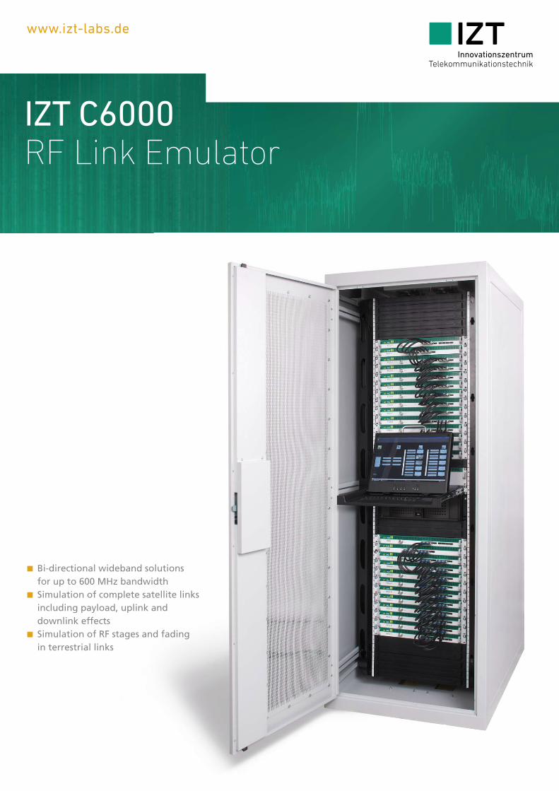
Bi-directional wideband solutions for up to 600 MHz bandwidth Simulation of complete satellite links including payload, uplink and downlink effects Simulation of RF stages and fading in terrestrial links
www.izt-labs.de
IZT C6000RF Link Emulator
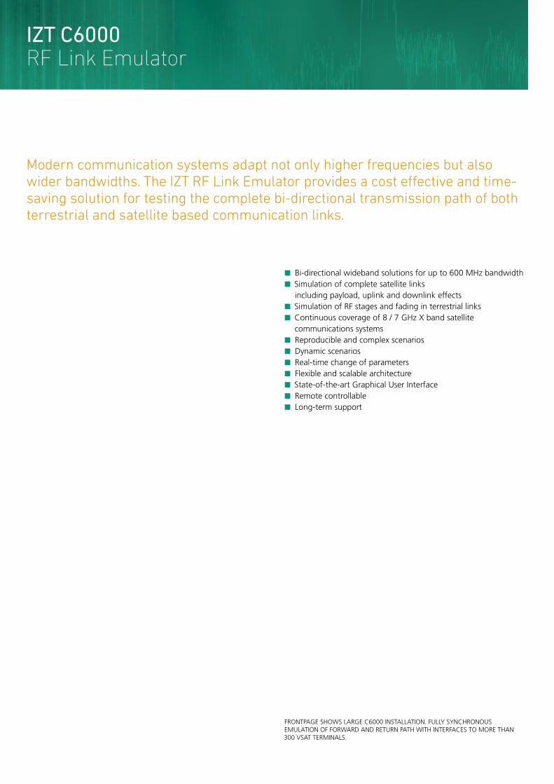
Modern communication systems adapt not only higher frequencies but also wider bandwidths. The IZT RF Link Emulator provides a cost eff ective and time-saving solution for testing the complete bi-directional transmission path of both terrestrial and satellite based communication links.
FRONTPAGE SHOWS LARGE C6000 INSTALLATION. FULLY SYNCHRONOUS EMULATION OF FORWARD AND RETURN PATH WITH INTERFACES TO MORE THAN 300 VSAT TERMINALS.
Bi-directional wideband solutions for up to 600 MHz bandwidth Simulation of complete satellite links including payload, uplink and downlink effects Simulation of RF stages and fading in terrestrial links Continuous coverage of 8 / 7 GHz X band satellite communications systems Reproducible and complex scenarios Dynamic scenarios Real-time change of parameters Flexible and scalable architecture State-of-the-art Graphical User Interface Remote controllable Long-term support
IZT C6000RF Link Emulator
IZT C6000 2 | 3
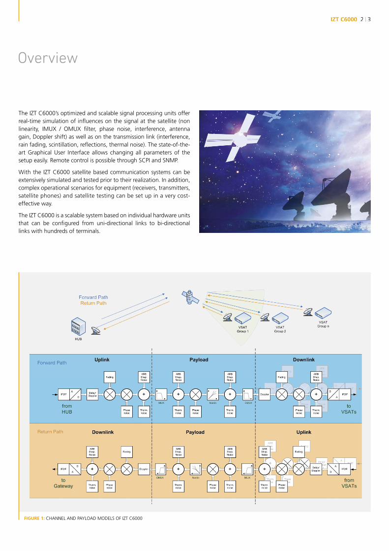
The IZT C6000’s optimized and scalable signal processing units offer real-time simulation of infl uences on the signal at the satellite (non linearity, IMUX / OMUX fi lter, phase noise, interference, antenna gain, Doppler shift) as well as on the transmission link (interference, rain fading, scintillation, refl ections, thermal noise). The state-of-the-art Graphical User Interface allows changing all parameters of the setup easily. Remote control is possible through SCPI and SNMP.
With the IZT C6000 satellite based communication systems can be extensively simulated and tested prior to their realization. In addition, complex operational scenarios for equipment (receivers, transmitters, satellite phones) and satellite testing can be set up in a very cost-effective way.
The IZT C6000 is a scalable system based on individual hardware units that can be confi gured from uni-directional links to bi-directional links with hundreds of terminals.
FIGURE 1: CHANNEL AND PAYLOAD MODELS OF IZT C6000
Overview

UPLINK
PAYLOAD
DOWNLINK
Thermal Noise
Thermal Noise
Phase Noise
Phase Noise
Phase Noise
Interferer
Interferer 1
Interferer 2
InterfererGain
Gain
IMUX OMUXNONLIN
Gain
Doppler
FrequencyOffset
InbandNoise
DopplerRain Fade Rain Fade
a INGRAPH
INGRAPH
INGRAPH
OUTGRAPH
OUTGRAPH
OUTGRAPHa
ALC
UPLINK
PAYLOAD
DOWNLINK
Thermal Noise
Thermal Noise
Phase Noise
Phase Noise
Phase Noise
Interferer
Interferer 1
Interferer 2
InterfererGain
Gain
IMUX OMUXNONLIN
Gain
Doppler
FrequencyOffset
InbandNoise
DopplerRain Fade Rain Fade
a INGRAPH
INGRAPH
INGRAPH
OUTGRAPH
OUTGRAPH
OUTGRAPHa
ALC
FIGURE 2: EXAMPLE OF A RAIN FADE PROFILE
FIGURE 3: BLOCKDIAGRAM OF UPLINK EFFECTS
FIGURE 4: BLOCKDIAGRAM OF DOWNLINK EFFECTS
Channel Eff ects
DELAY
The IZT C6000 can simulate a variable link delay of up to 800 ms in each direction. Additionally, its variation is tied to the Doppler simulation of the link. It is continuously variable to simulate actual movement of the payload. Variations will resemble a linear change of distance between transmitter and receiver.
DOPPLER
The IZT C6000 provides the ability to simulate time-variant, phase continuous Doppler frequency profi les. The profi les can either be based on math functions or on time indexed orbit description (ECEF) and ground site descriptions for transmitters and receivers. The Doppler simulation covers up to 24 hours of satellite movement.
RAIN FADE
To simulate rain fade, the IZT C6000 has the capability to apply time-varying attenuation profi les. Uplink Power Control (UPC) effects can be included in rain fade simulations by defi ning clear sky EIRP and maximum EIRP. The IZT C6000 provides a profi le depth of up to 24 hours at a 1 millisecond time resolution.
FIXED ATTENUATION
Fixed offsets in attenuation representative of static clear sky condi-tions can be applied.
INTERFERENCE
The C6000 facilitates several instances of interference signal gen-erators to emulate for example in-band adjacent beam co-channel interference.The interference waveform generator supports AWGN, CW, and sev-eral types of PSK and QAM modes. Bandwidth and center frequency of the interference are variable and user controllable. The interfer-ence signal level is settable relative to the carrier signal level.Every instance of the arbitrary waveform generator holds up to 3.5 GB of data.
THERMAL NOISE
AWGN generators in both uplink and downlink provide the means to emulate channel AWGN to refl ect constant noise such as antenna and receiver noise temperature. The AWGN signal level is settable relative to the carrier signal level.

IZT C6000 4 | 5UPLINK
PAYLOAD
DOWNLINK
Thermal Noise
Thermal Noise
Phase Noise
Phase Noise
Phase Noise
Interferer
Interferer 1
Interferer 2
InterfererGain
Gain
IMUX OMUXNONLIN
Gain
Doppler
FrequencyOffset
InbandNoise
DopplerRain Fade Rain Fade
a INGRAPH
INGRAPH
INGRAPH
OUTGRAPH
OUTGRAPH
OUTGRAPHa
ALC
Specifi ed phase noise mask:
Satellite Payload Eff ects
LINEAR FILTER DISTORTION (IMUX/OMUX)
The IZT C6000 provides two digital fi lters on either end of the payload simulation to mimic the satellite’s IMUX and OMUX fi l-ter amplitude and group delay response. The user may either specify the fi lter coeffi cients directly or provide a complex fre-quency response, which will be transformed into a FIR fi lter by the IZT C6000 control software. IMUX and OMUX fi lters are independent.
PHASE NOISE
The IZT C6000 supports an accurate phase noise simulation with up to 37.5 MHz bandwidth. The user can specify a desired frequency response or mask (noise power density versus frequency).Phase noise can be emulated at various stages of the IZT C6000, representing transmitter, receiver and satellite phase noise perfor-mance.As an example, the phase noise profi le for “DVB-S2 typical“ is shown in fi gure 5. The total (RMS) phase modulation is adjustable during the simulation. The exceptional underlying phase noise performance of the IZT C6000 allows simulating phase noise introduced by typical payload frequency conversion stages.
FIGURE 5: SIMULATED PHASE NOISE “DVB-S2 TYPICAL”
FIGURE 6: BLOCKDIAGRAM OF PAYLOAD EFFECTS
-25 dBc/Hz @ 100 Hz; -50 dBc/Hz @ 1 kHz; -73 dBc/Hz @ 10 kHz; -93 dBc/Hz @ 100 kHz; -103 dBc/Hz @ 1 MHz; -114 dBc/Hz @ >10 MHz
AUTOMATIC LEVEL CONTROL (ALC)
The IZT C6000 provides automatic level control (ALC) simulation. This is emulating the effect of additional payload noise due to the ALC loop increasing the forward payload gain to compensate for the de-creased signal strength at the satellite’s input for example caused by rain fade.
LTWTA NONLINEARITY
The IZT C6000 emulates the nonlinear response of the payload LTWTA by providing AM/AM and Phase versus IBO modeling. The user can either use any of the generic models or use his own actual measured AM/AM and Phase versus IBO data to emulate the LTWTA nonlinear response.Real-time measurements of the signal amplitude statistics at the input and output of the nonlinearity simulation provide the user with valuable feedback about the current operating point of the non-linearity.The current operating point of the LTWTA is confi gured dynamically by setting the IBO via the Graphical User Interface.
THERMAL NOISE AND IN-BAND NOISE
Two AWGN generators provide the means to emulate thermal noise effects at the input of the payload and in-band noise to represent the LTWTA noise. The AWGN signal level is settable relative to the carrier signal level.
INTERFERENCE
Two independent interference signal generators provide the capabil-ity to add interference induced by transponder loading. The inter-ferers can be added both before and after the LTWTA nonlinearity emulation.
OTHER EFFECTS
The IZT C6000 can emulate fi xed frequency offsets representative of transponder frequency translation offsets and fi xed attenuation offsets representative of static variations in payload gain.
PAYLOAD PRESET
The payload preset dialog allows the user to quickly confi gure the payload IMUX, OMUX, phase noise and nonlinearity based on the satellite channel in one single step.
Control Software
NONLINEARITY DISPLAY
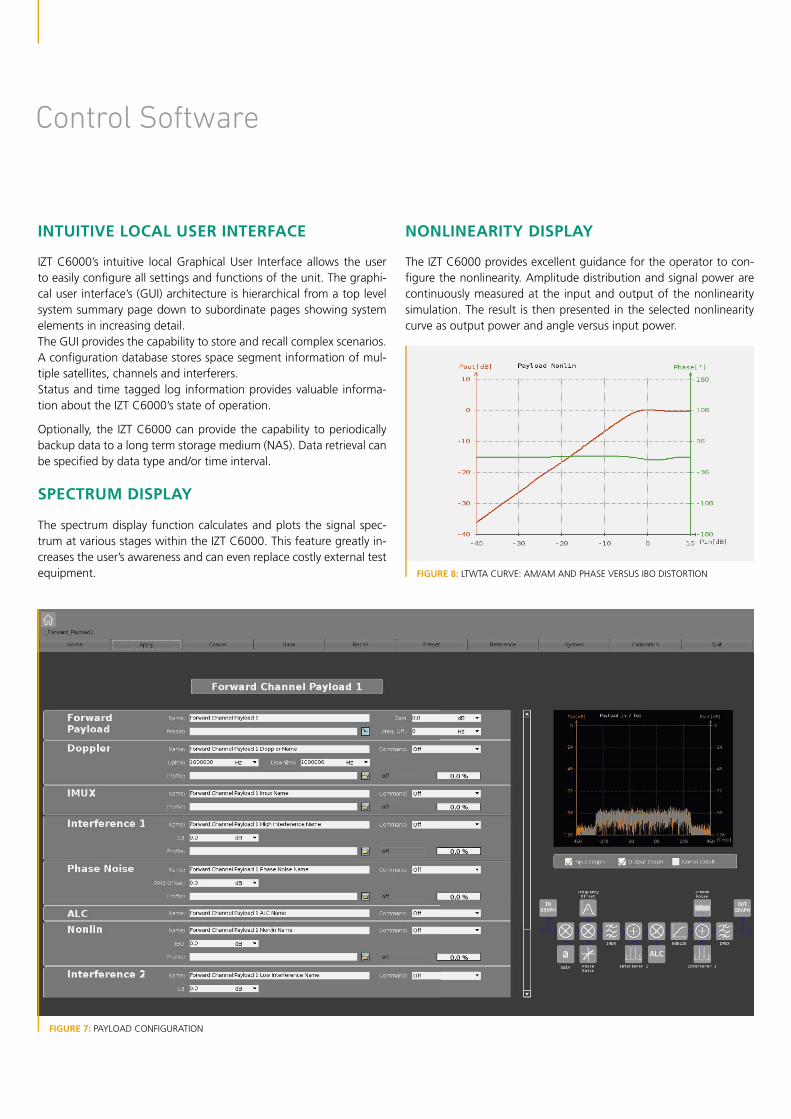
The IZT C6000 provides excellent guidance for the operator to con-fi gure the nonlinearity. Amplitude distribution and signal power are continuously measured at the input and output of the nonlinearity simulation. The result is then presented in the selected nonlinearity curve as output power and angle versus input power.
INTUITIVE LOCAL USER INTERFACE
IZT C6000’s intuitive local Graphical User Interface allows the user to easily confi gure all settings and functions of the unit. The graphi-cal user interface’s (GUI) architecture is hierarchical from a top level system summary page down to subordinate pages showing system elements in increasing detail.The GUI provides the capability to store and recall complex scenarios. A confi guration database stores space segment information of mul-tiple satellites, channels and interferers.Status and time tagged log information provides valuable informa-tion about the IZT C6000’s state of operation.
Optionally, the IZT C6000 can provide the capability to periodically backup data to a long term storage medium (NAS). Data retrieval can be specifi ed by data type and/or time interval.
SPECTRUM DISPLAY
The spectrum display function calculates and plots the signal spec-trum at various stages within the IZT C6000. This feature greatly in-creases the user’s awareness and can even replace costly external test equipment. FIGURE 8: LTWTA CURVE: AM/AM AND PHASE VERSUS IBO DISTORTION
FIGURE 7: PAYLOAD CONFIGURATION
IZT C6000 6 | 7
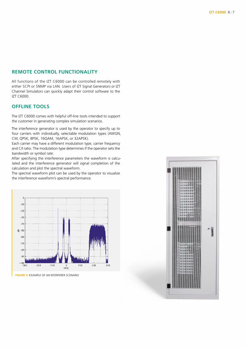
FIGURE 9: EXAMPLE OF AN INTERFERER SCENARIO
REMOTE CONTROL FUNCTIONALITY
All functions of the IZT C6000 can be controlled remotely with either SCPI or SNMP via LAN. Users of IZT Signal Generators or IZT Channel Simulators can quickly adapt their control software to the IZT C6000.
OFFLINE TOOLS
The IZT C6000 comes with helpful off-line tools intended to support the customer in generating complex simulation scenarios.
The interference generator is used by the operator to specify up to four carriers with individually, selectable modulation types (AWGN, CW, QPSK, 8PSK, 16QAM, 16APSK, or 32APSK). Each carrier may have a different modulation type, carrier frequency and C/I ratio. The modulation type determines if the operator sets the bandwidth or symbol rate. After specifying the interference parameters the waveform is calcu-lated and the interference generator will signal completion of the calculation and plot the spectral waveform. The spectral waveform plot can be used by the operator to visualize the interference waveform’s spectral performance.

Architecture and System Scalability
HUB
UPLINKDOWNLINK
UPLINKDOW
NLINK
UPLINK
DOW
NLINK
UPLIN
KD
OW
NLIN
K
UPLIN
K
DOW
NLINK
PAYLOADPAYLOAD
VSATGROUP 1
VSATGROUP 2
VSATGROUP 3
VSATGROUP 4
FIGURE 10: EXAMPLE BI-DIRECTIONAL SYSTEM
Individual RF and signal processing units can be interconnected to scale the IZT C6000 to the customer specifi c application.

IZT C6000 8 | 9
OPTION IZT C6000-UPL UPLINK
Uplink unit: RF downconversion stages, A/D conversion and digital signal processing of the uplink path. Multiple independent uplink units can be combined to provide an aggregated signal to the payload.
OPTION IZT C6000-PLD PAYLOAD
Payload unit: digital signal processing of payload effects.
OPTION IZT C6000-DNL DOWNLINK
Downlink unit: digital signal processing, D/A conversion and RF upconversion of the downlink path. Multiple independent downlink units can be connected to the payload.
OPTION IZT C6000-CSU CENTRAL SYNCHRONIZATION UNIT
A central synchronization unit provides trigger and clock signals to all hardware units. This ensures sample synchronized data processing and coherent emulation of both forward and return paths.The IZT C6000-CSU provides calibration for the complete IZT C6000 system, reducing required maintenance to a minimum.
OPTION IZT C6000-NAS NETWORK ATTACHED STORAGE
An optional Network Attached Storage (NAS) with 3 TB provides a long term data backup, for example for disaster recovery. All simulation relevant data such as confi gurations, profi les or interferer data is automatically stored on a regular basis for later retrieval.
OPTION IZT C6000-SVR SERVER
The monitor and control server hosts the Graphical User Interface, the remote control interface and confi gures the individual uplink, payload and downlink units.
OPTION IZT C6000-DSPL DISPLAY
An integrated high performance, 19 inch rackmount display and key-board unit. The 17” TFT Wide LCD display provides a resolution of 1920 x 1200.
CONFIGURATION EXAMPLES
Example 1:
A basic uni-directional system can be confi gured by using one uplink (IZT C6000-UPL), one payload (IZT C6000-PLD) and one downlink (IZT C6000-DNL).
Example 2:
A bi-directional system with one hub, one payload and four indepen-dent VSAT terminal groups is emulated by using fi ve uplink units (IZT C6000-UPL), two payload units (IZT C6000-PLD) and fi ve downlink units (IZT C6000-DNL) as shown in fi gure 10.
FIGURE 11: RACK INSTALLATION CONSISTING OF 11x UPLINKS,
12x DOWNLINKS AND 3x PAYLOADS

Specifications IZT C6000
Effects
Delay range 10 μs to 800 ms
Delay resolution 1 ns
Delay accuracy 1 ns
Doppler shift range ±1 MHz (phase continuous)
Doppler shift resolution 1 Hz
Doppler shift accuracy 0.1 Hz
Doppler shift change rate 100 updates/s
Fixed frequency offset range ±1 MHz
Fixed frequency offset resolution 1 Hz
Fixed frequency offset accuracy < 0.1 Hz
Fading attenuation range 70 dB
Fading attenuation resolution 0.1 dB
Fading attenuation accuracy < 0.1 dB
Fading attenuation change rate 1000 updates/s
Fixed attenuation range -10 to +10 dB
Fixed attenuation resolution 0.1 dB
Interferer type CW, AWGN, QPSK, 8PSK, 16QAM, 16APSK, 32APSK (up to four interferers simultaneously)
Interferer bandwidth Variable
Interferer center frequency Variable within the 600 MHz system bandwidth
Interferer signal level Adjustable relative to input carrier signal level (C/I)
Interferer accuracy < ±0.5 dB from commanded level
Thermal noise signal level Adjustable relative to input carrier signal level (C/N0)
Thermal noise resolution 0.1 dB
Thermal noise accuracy < ±0.5 dB/Hz from commanded level
Phase noise Emulates filter responses
Phase noise accuracy < ±0.5 dB from commanded filter response
Linear filter distortion (IMUX, OMUX) Up to 1024 complex FIR coefficients
Linear filter distortion amplitude accuracy < ±0.5 dB amplitude ripple error
Linear filter distortion group delay accuracy < 1 ns group delay error
Nonlinearity AM/AM distortion versus IBO < ±0.1 dB
Nonlinearity phase distortion versus IBO < ±0.5°
Nonlinearity dynamic range 60 dB

IZT C6000 10 | 11
RF performance
RF input frequency range 450 MHz or 1250 MHz IF(RF frequencies on request)
RF output frequency range 450 MHz or 1250 MHz IF(RF frequencies on request)
Amplitude response < ±0.5 dB, typical
Group delay < ±1 ns, typical
Bandwidth 600 MHz
RF input level +10 dBm, max
RF output level +10 dBm, max
Input VSWR < 1.2 : 1
Output VSWR < 1.2 : 1
Impedance 50 Ω
RF environmental
Nominal operating temperature 18°C to 25°C
Max operating temperature 0°C to 40°C
Storage temperature -10°C to +60°C
Humidity 10% to 90%, non condensing
Altitude 1000 m, AMSL
Power supply 100 V to 240 V (AC), 50 Hz to 60 Hz
Ordering Guide
IZT C6000 Hardware options
IZT C6000-PLD Payload emulation unit
IZT C6000-UPL Uplink emulation unit
IZT C6000-DNL Downlink emulation unit
IZT C6000-SVR Monitor and control server, switch
IZT C6000-DSPL Keyboard and display, 19 inch rackmount
IZT C6000-NAS 3 TB network attached storage for data backup
IZT C6000-CSU Central synchronization unit
IZT C6000 Software options
IZT C6000-101 Delay
IZT C6000-104P IMUX/OMUX fi lter, payload
IZT C6000-106P True Doppler simulation, up/downlink
IZT C6000-107U Thermal noise, uplink
IZT C6000-107P In-band noise, payload
IZT C6000-107D Thermal noise, downlink
IZT C6000-109U Phase noise simulation, uplink
IZT C6000-109P Phase noise simulation, payload
IZT C6000-109D Phase noise simulation, downlink
IZT C6000-110P Nonlinearity simulation, payload
IZT C6000-111U Rain fade (attenuation profi les), uplink
IZT C6000-111D Rain fade (attenuation profi les), downlink
IZT C6000-112U ARB incl interferer generator, uplink
IZT C6000-112P ARB incl interferer generator, payload
IZT C6000-112D ARB incl interferer generator, downlink
IZT C6000-114 Spectrum display
SPECIFICATION SUBJECT TO CHANGE WITHOUT FURTHER NOTICE.
8526 Virginia Meadows Drive Manassas, VA 20109 Ph: (703) 365-2330 www.hvtechnologies.com [email protected]
North America Sales, Service & Support:

IZT C6000RF Link Emulator
About IZT The Innovationszentrum fuer Telekommunikations technik GmbH IZT specializes in the most advanced digital signal processing and fi eld programmable gate array (FPGA) designs in combination with high frequency and microwave technology.
The product portfolio includes equipment for signal generation, receivers for signal monitoring and recording, transmitters for digital broadcast, digital radio systems, and channel simulators. IZT offers powerful platforms and customized solutions for high signal bandwidth and real-time signal processing applications. The product and project business is managed from the principal offi ce located in Erlangen/Germany. IZT distributes its products worldwide together with its international strategic partners.The IZT quality management system is ISO 9001:2000 certifi ed.
INNOVATIONSZENTRUM FÜR TELEKOMMUNIKATIONSTECHNIK GMBH IZT AM WEICHSELGARTEN 5 · 91058 ERLANGEN, GERMANY GENERAL MANAGER: RAINER PERTHOLD · TEL: +49 (0)9131 9162-0 · FAX: -190 · [email protected] · WWW.IZT-LABS.DE
8526 Virginia Meadows Drive Manassas, VA 20109 Ph: (703) 365-2330 www.hvtechnologies.com [email protected]
North America Sales, Service & Support: