j. electrical systems x-x (xxx): x-xxjournal.esrgroups.org/jes/papers/6_1_2.pdf · electric...
TRANSCRIPT

Corresponding author : M. Rachek Département d’Electrotechnique, Université Mouloud Mammeri, BP 17 RP 15000, Tizi-Ouzou – Algérie [email protected] Copyright © JES 2009 on-line : journal.esrgroups.org/jes
M. Rachek B. Moussaoui Y. Nekmouche S. NaitLarbi T. Merzouki
J. Electrical Systems x-x (xxx): x-xx
Regular paper
Two-axis Magnetically Coupled Electric Circuits for Modeling of Dual-
Stator Induction Machines Under Healthy and Electric Failures
The aims of this paper is to present an accurate two-axis model for the analysis and diagnosis of dual-stator induction machine under healthy and windings electrical faults conditions. While incorporating the stator and rotor windings functions, the developed model is based on the magnetically coupled electric circuits equations expressed in two different coordinate systems, and combined with the mechanical equations through the electromagnetic torque. The obtained time-differential state equations system is implemented under Matlab environment and numerically solved using the fourth order Rung-Kutta method with variable step time corrected at each rotor displacement. The computer simulation model can be used under unbalanced parameters or asymmetries operating conditions due to faults. A dual stator induction machine is simulated under healthy operating, and faults due to stator electrical inter-turns short-circuits, or stator and rotor broken phases conditions. The studied faults impact is analyzed while focusing on the currents, electromagnetic torque and rotor speed behaviors.
Keywords: Dual stator induction machine, electric circuits magnetically coupled model, inter-turn short circuits, stator phases breakdown, broken rotor bars.
1. Nomenclature
21 , ss are respectively the indexes of the first star and second star of the stator windings. r is related to the rotor index.
fss
cba lL ,,, are respectively the self and leakage inductances of the stator windings
frr lL , are respectively the self and leakage inductances of the rotor windings
rs RR , are respectively the resistance of the stator/rotor
srm is the mutual inductance between stator and rotor windings.
21ssm is the mutual inductance between stator windings.
rr θω , are the rotor speed and the angular position.
loadem C,C are respectively the electromagnetic and load torque.
f,J are respectively the shaft inertia and the friction coefficient scc
scc iu , are respectively the voltage and current of short-circuits winding.
so
so iu , are respectively the voltage and current of broken winding.
2. Introduction
Multiphases electrical machines are finding favor in some variable-speed drive and specialized critical applications where high reliability and security is demanded such as electric/hybrid vehicles, aerospace applications, ship propulsion, and high power applications. They possess several advantageous over conventional three-phases drives

2
counterparts such as: reducing the amplitude and increasing the frequency of pulsating torques, reducing the rotor harmonic currents and the stator per phase currents without increasing the voltages per phases and the power in same frame [1-2].
Among of the multiphases machines, the most used are the Dual-Stator Induction Machines (DSIM) offering power segmentation are very attractive for high power applications, since they allow the use of lower rating power electronic devices able to function at a high switching frequency. Nonetheless, failures can appear, so we have to monitor the process or the multiphase machines and there (DSIM) type in order to limit the dangerousness of the defective process and to limit the coast of the maintenance drives in many branches of the industry. As a consequence of electrical or mechanical faults, which may arise during the operation period, many electrical machines are operating at asymmetrical conditions. The basis of reliable diagnosis is an understanding of the electric, magnetic and mechanical behavior of the machine in healthy and under fault conditions [3-4].
In general, condition monitoring schemes have concentrated on sensing specific failures modes in one of three induction motors components: the stator, the rotor, or the bearings. Even though thermal and vibration monitoring have been utilized for decades, most of the recent research has been directed toward electrical monitoring of the motor with emphasis on inspecting the stator current of the motor. All of the presently available techniques require the user to have some degree of expertise in order to distinguish a normal operating condition from a potential failure mode [4-6].
The aims of the present paper, is to develop an accurate transient model of Dual-Star Induction Machines (DSIM) under healthy and windings faults conditions operations. The proposed original phase axes model is based on a coupled magnetic circuits approach. The original phases axes model equations is based on the expression of elementary electric equations of each stator and rotor windings, respectively in the fixed coordinate system, and the rotating coordinate one. Both equations are associated to the mechanical equations through the torque, and then a differential equations system model is obtained.
The model establishes a relation between a state vector formed by the windings currents, the speed, the angular displacement, and the external rated voltages through the mechanical parameters, the constant resistances and self-inductances matrices, and particularly the mutual inductance-angular displacement dependence matrices. The model can be used when the windings parameters of the phases are not balanced with very few restrictive assumptions. The cases of (DSIM) under healthy, stator windings inter-turns short circuits, stator phase breakdown, and broken bars are studied.
3. Healthy Model of Dual-Stator-IM
Consider a (DSIM) in which the two stator stars windings connection are spatially displaced by a fixed electrical angle α , classically shifted to be equal to 30°. A (DSIM) has two three-phase stator windings sets, which will be referred as “stators” throughout this paper for conciseness. The windings are modelled as a serials resistance and electromotives forces, such as showed by the “Fig.1”. The assumptions made concern the infinite permeability of iron, uniform air gap, stator windings identical, negligible slotting effect [7],
In general the servo-motor is controlled in the synchronously rotating reference frame to obtain the couplings between the motor current and the torque. In the case of the control without position sensor, the servo-motor do not possess any information on the position θ.

3
In that case the α−β axis are supposed to replace the d-q axis in the control. Supposing that the axis α is necessarily non adjusted with the axis d, the rotor angle θ is defined as the angle between the axis α and the phase U of the motor.
The control is achieved by the estimation of the rotor position θ.
Fig. 1: Windings configuration of the Dual-Stator Induction Machine.
3.1 Native Mathematical Model
According to basic circuit theory of the Kirchoff’s laws and the classical assumptions, the (DSIM) original phase axes model can be expressed as follows :
[ ] [ ] [ ][ ] [ ] [ ][ ] [ ]φ
φφ
dtdIR
dtd
II
RR
uuu r
s
r
s
rr
ssr
s+=
⎥⎥⎦
⎤
⎢⎢⎣
⎡+
⎥⎥⎦
⎤
⎢⎢⎣
⎡⎟⎟⎠
⎞⎜⎜⎝
⎛=
⎥⎥⎦
⎤
⎢⎢⎣
⎡=
××
××
3363
36660
0 (1)
[ ][ ] ( )[ ]
( )[ ] [ ] [ ][ ]ILII
LM
MLr
s
rrtr
SR
SRssr
s=
⎥⎥⎦
⎤
⎢⎢⎣
⎡⎟⎟⎠
⎞⎜⎜⎝
⎛=
⎥⎥⎦
⎤
⎢⎢⎣
⎡=
××
××
3363
6366θ
θ
φφφ (2)
Where the elementary vector voltage and current are defined, such as:
[ ]trsc
sb
sa
sc
sb
sa
s uuuuuuu222111
,,,,,= [ ]trrC
rB
rA
r uuuu ,,=
[ ]trsc
sb
sa
sc
sb
sa
s IIIIIII222111
,,,,,= [ ]trrC
rB
rA
r IIII ,,=
The matrices resistance, self-inductance of the stator and the rotor windings, and their mutual inductances matrix are respectively : [ ]ssR , [ ]ssL , [ ]rrR , [ ]rrL and ( )[ ]θSRM .

4
Since the windings resistance values for the stator and the rotor are not necessarily equal, the stator and rotors resistances matrices are given such as:
[ ]
⎥⎥⎥⎥⎥⎥⎥⎥
⎦
⎤
⎢⎢⎢⎢⎢⎢⎢⎢
⎣
⎡
=×
sc
sbb
sa
sc
sb
sa
ss
RR
RR
RR
R
2
2
2
1
1
1
66
000000000000000000000000000000
[ ]⎥⎥⎥
⎦
⎤
⎢⎢⎢
⎣
⎡=×
3
2
1
3300
0000
r
r
r
rrR
RR
R (3.a)
Let us defined the angle 32πβ = between the two rotor windings, and the two stator windings of each stars 1 or 2. The stator and rotor self and mutual inductance matrices are written as:
[ ]
( ) ( ) ( ) ( ) ( )( ) ( ) ( ) ( ) ( )( ) ( ) ( ) ( ) ( )( ) ( ) ( ) ( ) ( )
( ) ( ) ( ) ( ) ( )( ) ( ) ( ) ( ) ( )
⎥⎥⎥⎥⎥⎥⎥⎥
⎦
⎤
⎢⎢⎢⎢⎢⎢⎢⎢
⎣
⎡
+
⎥⎥⎥⎥⎥⎥⎥⎥
⎦
⎤
⎢⎢⎢⎢⎢⎢⎢⎢
⎣
⎡
−+−−−+
−+−−+−
+−−−+−
=×
sc
sb
sa
sc
sb
sa
ssss
LL
LL
LL
mL
2
2
2
1
1
1
2166
000000000000000000000000000000
1coscoscoscoscoscos1coscoscoscos
coscos1coscoscoscoscoscos1coscos
coscoscoscos1coscoscoscoscoscos1
ββαβαβαβββααβαβββαβαααβαβαβββααβαβββαβααββ
(3.b)
( )[ ]( ) ( ) ( )
( ) ( ) ( )( ) ( ) ( )( ) ( )( ) ( )( )
( )( ) ( ) ( )( )( )( ) ( )( ) ( ) ⎥
⎥⎥
⎦
⎤
−−−+−+−−−−−−+−−
⎢⎢⎢
⎣
⎡
+−−++−
=×
αθβαθβαθβαθαθβαθβαθβαθαθ
θβθβθβθθβθβθβθθ
θ
rrr
rrr
rrr
rrr
rrr
rrr
srrSR mM
coscoscoscoscoscoscoscoscos
.
.
.
coscoscoscoscoscoscoscoscos
63 (3.c)
[ ]( ) ( )
( ) ( )( ) ( ) ⎥
⎥⎥
⎦
⎤
⎢⎢⎢
⎣
⎡+
⎥⎥⎥
⎦
⎤
⎢⎢⎢
⎣
⎡
−−
−=×
3
2
1
3300
0000
1coscoscos1cos
coscos1
r
r
r
rrrrL
LL
mLββ
ββββ
(3.d)
To the set of (1) and (2) equations, one must add the mechanical equations of the shaft:
( )rloademr fCC
Jdtd
ωω
−−=1 (4)

5
rr
dtd
ωθ
= (5)
With rr θω , denote the rotor speed and the angular position, loadem C,C are
respectively the electromagnetic and load torque, and f,J are respectively the shaft inertia and the friction coefficient
The electromagnetic torque emC is obtained from the magnetic stored co-energy coW .
[ ] ( )[ ]( )[ ] [ ] ⎥
⎦
⎤⎢⎣
⎡⎥⎦
⎤⎢⎣
⎡⋅⎥
⎦
⎤⎢⎣
⎡=
r
s
rrtr
rSR
rSRsstr
r
sco I
ILM
MLII
Wθ
θ21 (6)
[ ] [ ][ ] [ ] [ ][ ] [ ] ( )[ ][ ]
[ ] ( )[ ] [ ]str
rSRtr
r
rrSRtr
srrrtr
rssstr
sco
IMI
IMIILIILIW
θ
θ
21
21
21
21
+++=
It is obvious that the self inductance matrices [ ]ssL and [ ]rrL contain only constant
elements, and if P denote the number of motor poles it is clear that any inductance which is a function of angular displacement undergoes 2P complete cycles as rmθ varies from
0 to π2 . Hence the electrical displacement in electrical radians is ( )2Prmr θθ = .Since emC is a scalar, each of the two terms comprising emC must be a
scalar and equal to each others. In terms of rθ the torque is finally given as:
[ ] ( )[ ] [ ]rr
rSRtrs
r
co
rm
coem I
MIPWPW
C ⎟⎟⎠
⎞⎜⎜⎝
⎛∂
∂=⎟⎟
⎠
⎞⎜⎜⎝
⎛∂∂
=∂∂
=θθ
θθ 22 (7)
3.1 Magnetically Coupled Electric Circuits State Model Incorporating flux equation (2) in voltages equations (1) and electromagnetic torque
expression (7) in the mechanical equation (4), we can write the differential equations system which governs the behavior of the dual stator induction machines.
[ ] ( )[ ] [ ] ( )[ ] [ ] ( )[ ] [ ]uLILd
dRLIdtd
rrr
rr11 −− +⎟⎟
⎠
⎞⎜⎜⎝
⎛+= θθ
θωθ (8)
[ ] ( )[ ] [ ] loadrrr
trr CJJ
fILd
dIJ
Pdt
d 12
−−⎭⎬⎫
⎩⎨⎧
= ωθθ
ω (9)
At this stage a special attention is paid to the greatly dependence between the angular rotor displacement and the inductance and derivative inductance inverse matrices which their accuracy calculations deicide of the accuracy and effectiveness of the magnetically electric circuits coupled model.

6
Equations (4)-(8) and (9) can be written as a differential algebraic state system which governs the induction machine’s:
[ ] [ ] [ ] [ ][ ] [ ] [ ] [ ]
[ ] [ ][ ] [ ]
[ ] ( )[ ] [ ] [ ]
( )[ ] [ ] [ ] [ ]
[ ] [ ][ ] [ ]
⎥⎥⎥⎥⎥
⎦
⎤
⎢⎢⎢⎢⎢
⎣
⎡
⎥⎥⎥⎥⎥⎥⎥
⎦
⎤
⎢⎢⎢⎢⎢⎢⎢
⎣
⎡
−
+
⎥⎥⎥⎥⎥
⎦
⎤
⎢⎢⎢⎢⎢
⎣
⎡
⎥⎥⎥⎥
⎦
⎤
⎢⎢⎢⎢
⎣
⎡
−
=⎟⎟⎟
⎠
⎞
⎜⎜⎜
⎝
⎛−
r
r
r
s
rs
rrr
trrSR
r
r
rSRrss
r
r
r
s
rrtr
rSR
rSRss
load
II
dtd
fCC
Rd
Mdd
MdR
II
JLM
ML
Cu
θωθ
θω
θθ
ω
θω
θθ
01000
00
00
100000000)(00)(
0
(10)
To facilitate the equations treatments and their generalization for each multi-phases machines, the inductance matrices and re-written such as:
-The mutual inductance between the stator and rotor windings is expressed as:
( )[ ]⎥⎥⎥⎥
⎦
⎤
⎢⎢⎢⎢
⎣
⎡
=ssssss
ssssss
ssssss
srSR
ffffff
ffffff
ffffff
mM
132132
213213
321321
111
222111
222111
θ (11.a)
where, ( )( )1cos1 −+= if rs
i βθ and ( )( )1cos2 −+−= if rs
i βαθ 3,2,1=i
- The derivative angular of the previous mutual inductance is expressed as:
( )[ ]
⎥⎥⎥⎥
⎦
⎤
⎢⎢⎢⎢
⎣
⎡
=⎥⎦
⎤⎢⎣
⎡
ssssss
ssssss
ssssss
srr
rSRr
gggggg
gggggg
gggggg
md
Md
132132
213213
321321
111
222111
222111
θθω (11.b)
Where ⎟⎠⎞⎜
⎝⎛= 11 s
ir
si f
ddgθ
and ( )22 si
r
si f
ddgθ
= 3,2,1=i
And the related mechanical elements [ ]sC and [ ]rC are calculated as follows:
[ ] [ ] [ ]rtrsrs IHm
C ⋅⎟⎠
⎞⎜⎝
⎛=
2 (11.c)

7
[ ] [ ] [ ]ssrr IHm
C ⋅⎟⎠
⎞⎜⎝
⎛=
2 (11.d)
Where the electromechanical coupling matrix is given such as:
[ ]⎟⎟⎟⎟⎟
⎠
⎞
⎜⎜⎜⎜⎜
⎝
⎛
=222111
222111
222111
123123
312312
231231
ssssss
ssssss
ssssss
hhhhhh
hhhhhh
hhhhhh
H (11.e)
Where ( )( )1sin1 −+= ih rsi βθ and ( )( )1sin1 −+−= ih r
si βαθ 3,2,1=i
The differential equations system (10) is solved using the Rung-Kutta algorithm with variable step time correction at each rotor displacement. This permit an accuracy calculation for the model with reducing the computation cost.
4. (DSIM) Models Under Stator Inter-Turn Short Circuits And Broken Bars
4.1. (DSIM) model with broken bars
There is no need to explicitly change the topology of the equivalent circuit of the stator
or rotor to take into account the phase breakdown or broken bars respectively. Inserting a higher resistance in the injured phase in the generalized model (10) during the simulation is sufficient. Generally, high power induction motors have squirrel-cage rotor, in the present work the rotor initially containing bN bars of bR resistance is considered as a secondary phase system composed with three windings circuits (phases). Each circuit is considered as
3bN resistance connected in parallel. Thus the normal rotor phase resistance is expressed as:
⎟⎠⎞
⎜⎝⎛
=
3NR
R br (12)
When bn defective bars induced ( ) bb nN −3 bars in parallel, the equivalent resistance is equal to:
bb
bdefectr
nN
RR
−⎟⎠
⎞⎜⎝
⎛=
3
(13)
Consequently, the increasing value of the rotor resistance is given by the difference between the health and defective resistance, explained such as:
8
bb
brr
defectr nN
nRRRR
33
−=−=Δ (14)
The rotor matrix resistance with broken bars become:
[ ]⎥⎥⎥
⎦
⎤
⎢⎢⎢
⎣
⎡ Δ+=×
3
2
1
3300
0000
r
r
r
rrR
RRR
R (15)
When one stator phase is breakdown the voltage sou appear, the fault condition is take
into account through increasing of the injured phase resistance until a zero current soi is
obtained. 4.2. (DSIM) under stator inter-turn short circuits
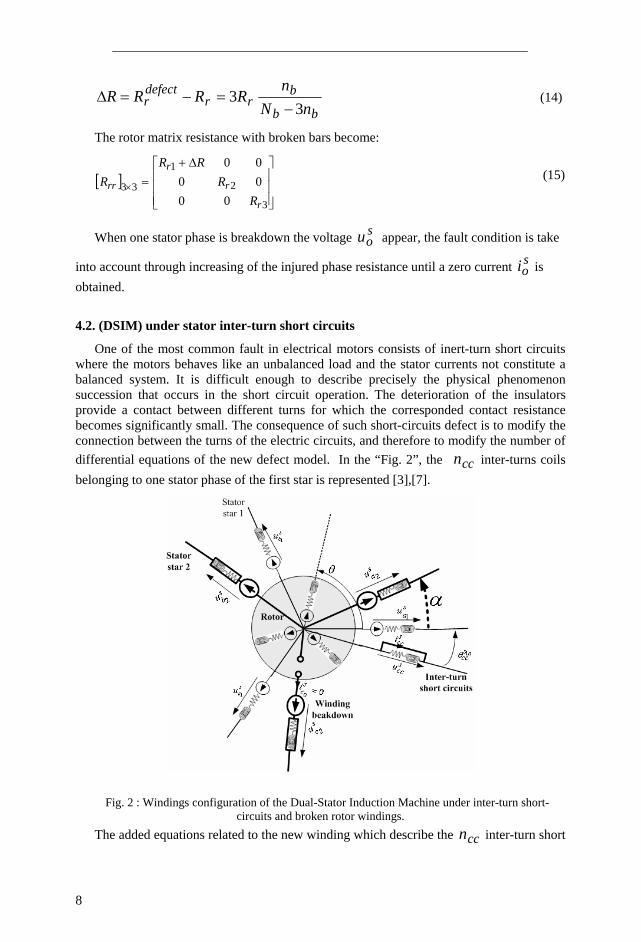
One of the most common fault in electrical motors consists of inert-turn short circuits where the motors behaves like an unbalanced load and the stator currents not constitute a balanced system. It is difficult enough to describe precisely the physical phenomenon succession that occurs in the short circuit operation. The deterioration of the insulators provide a contact between different turns for which the corresponded contact resistance becomes significantly small. The consequence of such short-circuits defect is to modify the connection between the turns of the electric circuits, and therefore to modify the number of differential equations of the new defect model. In the “Fig. 2”, the ccn inter-turns coils belonging to one stator phase of the first star is represented [3],[7].
Fig. 2 : Windings configuration of the Dual-Stator Induction Machine under inter-turn short-circuits and broken rotor windings.
The added equations related to the new winding which describe the ccn inter-turn short

9
circuits fed by sccu voltage and s
cci current of short-circuits coils of one stator phase
containing sn turn are:
[ ]ccccccscc dt
dIRu φ+⋅= (16)
[ ] [ ] ( )[ ] ( )[ ]( )( )[ ] [ ] ( )[ ]( ) ⎟
⎟⎟⎟
⎠
⎞
⎜⎜⎜⎜
⎝
⎛
⎟⎟
⎠
⎞
⎜⎜
⎝
⎛=
×××
×××
scc
r
s
rccrrr
trrSR
sccccrSRss
III
MLM
MML
133363
166366
θθ
θθφ (17)
[ ] ( )[ ]( ) ( )[ ]( ) [ ]⎟⎟⎟⎟
⎠
⎞
⎜⎜⎜⎜
⎝
⎛
⎥⎦⎤
⎢⎣⎡= ×××
scc
r
s
cctrr
ccrtrs
ccccccIII
LMM 111316 θθφ (18)
The additional elements of the resistances and inductances matrices dues to the short circuits percent ccη are given as follows:
[ ] sacccc RR 1⋅=η (19.a)
[ ] ( ) ( )sacccc LL 1
211 ⋅=× η (19.b)
( )[ ] ( )
( )( )( )( )
( )( )
coscos
coscoscos
cos
21
⎥⎥⎥⎥⎥⎥⎥⎥
⎦
⎤
⎢⎢⎢⎢⎢⎢⎢⎢
⎣
⎡
−−+−
−−+
⋅=
βαθβαθ
αθβθβθ
θ
ηθ
cc
cc
cc
cc
cc
cc
ssccscccc mM (19.c)
( )[ ] ( )( )
( )( )⎥
⎥⎥
⎦
⎤
⎢⎢⎢
⎣
⎡
−−+−
−⋅⋅=
βθθβθθ
θθηθ
rcc
rcc
rcc
srccrccr mM
coscos
cos (19.d)
( )[ ] ( )[ ]( )[ ] ⎥
⎥⎦
⎤
⎢⎢⎣
⎡⋅= r
ccr
sccccrs
ccrM
MM
θ
θθ / (19.e)

10
Where s
cccc n
n=η is percent of inter-turn short circuit and the injured phase is
associated with the ccθ angle [7].
Incorporating flux equations (17), (18) in the voltages equations (1), (16), and electromagnetic torque expression (7) including implicitly the short circuit effect through the currents in the mechanical equation (4), we can write the differential equations system which governs the behaviour of the dual stator induction machines.
( )[ ] ( )[ ]( )[ ] [ ]
( )[ ] ( )[ ]( )[ ] [ ]
[ ] ( )( )
( )[ ] ( )[ ]( )[ ] [ ]
⎥⎦
⎤⎢⎣
⎡⎟⎟⎟
⎠
⎞
⎜⎜⎜
⎝
⎛
⎥⎥⎦
⎤
⎢⎢⎣
⎡+
⎥⎥⎦
⎤
⎢⎢⎣
⎡
−−
−−
×⎥⎥⎦
⎤
⎢⎢⎣
⎡
+⎥⎦
⎤⎢⎣
⎡×
⎥⎥⎦
⎤
⎢⎢⎣
⎡=⎥
⎦
⎤⎢⎣
⎡
−
−
scccc
rscc
trr
rsccrr
rr
ccccsa
ccsa
ccrs
cctr
r
rsccrr
scccc
rscc
trr
rsccrr
scc
II
LM
MLd
dRRR
RRR
LM
ML
uu
LM
MLII
dtd
/
/
1
1
1
/
/
1
/
/
θ
θθθ
ω
θ
θθ
θ
θθ
(20)
( )[ ] ( )[ ]( )[ ] [ ]
loadrscccc
srcc
trr
srccrr
r
tr
scc
r CJJ
fII
LM
MLd
dII
JP
dtd 1
2−−⎥
⎦
⎤⎢⎣
⎡
⎪⎭
⎪⎬⎫
⎪⎩
⎪⎨⎧
⎥⎥⎦
⎤
⎢⎢⎣
⎡⎥⎦
⎤⎢⎣
⎡= ω
θ
θθθ
ω
(21) Equations (20), (21) and (9) can be written as a differential algebraic state system which
governs the dual stator induction machine’s under one phase stator inter-turn short circuits:
[ ] ( )[ ] ( )[ ] [ ] [ ]( )[ ] [ ] ( )[ ] [ ] [ ]
( )[ ]( ) ( )[ ]( ) [ ] [ ] [ ][ ] [ ] [ ][ ] [ ] [ ]
[ ] ( )[ ]( ) [ ] [ ] [ ]
( )[ ]( ) [ ] ( )[ ]( ) [ ] [ ]
[ ] ( )[ ]( ) [ ] [ ] [ ]
[ ] [ ] [ ][ ] [ ] [ ]
⎥⎥⎥⎥⎥⎥
⎦
⎤
⎢⎢⎢⎢⎢⎢
⎣
⎡
⎥⎥⎥⎥⎥⎥⎥⎥⎥⎥
⎦
⎤
⎢⎢⎢⎢⎢⎢⎢⎢⎢⎢
⎣
⎡
−
+
⎥⎥⎥⎥⎥⎥
⎦
⎤
⎢⎢⎢⎢⎢⎢
⎣
⎡
⎥⎥⎥⎥⎥⎥⎥
⎦
⎤
⎢⎢⎢⎢⎢⎢⎢
⎣
⎡
−
=
⎟⎟⎟⎟⎟⎟⎟⎟⎟⎟
⎠
⎞
⎜⎜⎜⎜⎜⎜⎜⎜⎜⎜
⎝
⎛
−⎥⎥⎥⎥
⎦
⎤
⎢⎢⎢⎢
⎣
⎡
r
r
scc
r
s
rs
cctrr
ccrr
r
rccr
rrrr
trrSR
rr
rSRr
rss
r
r
scc
r
s
cctrr
ccrtrs
cccc
rccrrr
trrSR
sccccrSRss
load
scc
r
s
III
dtd
fCC
RMd
d
Md
dRMd
d
Md
dR
III
JLMM
MLMMML
Cuuu
θωθ
θω
θθ
ωθθ
ω
θθ
ω
θω
θθ
θθ
θθ
0100000
000
00
000
10000000000
0000
0
(22)

11
The combination of the equations (1)-(2), and (3)-(5) with the short circuits equations (11)-(17), leads to the final reduced multi-turn state formulation model (19) of the (DSIM) under short-circuit turns of one stator star. The differential equations system (20) is solved using the fourth order Rung-Kutta method while the step time is chosen at each time as the inverse of the maximal eigen values of the state matrix.
5. Simulations Results and Discusions
To simulate the (DSIM) model, a native open computer program implemented under Matlab is used to perform calculation of inductances matrices and to simulate transient and steady state behavior of the (DSIM) were the main state formulation of the differential equations systems (10 ) and (19) are solved using the fourth order Rung-Kutta method.
The induction motor parameters are detailed in the appendix. The simulation results of the transient and steady state behaviour of the motor are obtained after numerically solving the differential algebraic equations system (10). The model program implemented under Matlab environment is open for interfaced with commercial softwares. The stator windings studied defects are different number of turn-to-turn short circuits. The analysed quantities are the speed, torque and the stator/rotor currents.
5.1. Stator Inter-turn shorts circuits faults Consider a case of inter-turn short circuits of one star of the stator phases. It mean that
5% turns of the phase “a” are shorted. The motor operate at its nominal state with a load torque imposed at st 8.0= . While the loaded motor steady state operation is achieved, a short-circuit of 5% turns is imposed at st 25.1= .
The obtained results for simulated operating modes, healthy no-load, healthy load and inter-turns short circuits with loaded (DSIM) are given by the following "Figs. 3-12". The results concern the studied quantities: speed, torque, stator and rotor phase currents.
Fig. 3: Speed under healthy and 5% inter-turns short-circuits of the loaded (DSIM).

12
Fig. 4: Torque under healthy and 5% inter-turns short-circuits of the loaded (DSIM).
Fig. 5: Current of the first star phase Sa1 current under healthy and 5% inter-turns short-circuits.

13
Fig.6: Current of first star phase Sb1 under healthy and 5% inter-turns short-circuits.
Fig. 7: Current of first star phase Sc1 under healthy and 5% inter-turns short-circuits.

14
Fig. 8: Current of second star phase Sa2 under healthy and 5% inter-turns short-circuits.
Fig. 9: Current of second star phase Sb2 under healthy and 5% inter-turns short-circuits.

15
Fig.10: Current of second star phase Sc2 under healthy and 5% inter-turns short-circuits.
Fig. 11: Current of rotor phase Ra under healthy and 5% inter-turns short-circuits.

16
Fig. 12: Current of rotor phase Rb under healthy and 5% inter-turns short-circuits.
Fig. 13: Current of rotor phase Rc under healthy and 5% inter-turns short-circuits.
Figs. 3, and 14, and Fig.4, show that the magnitude of the speed and torque signals increased at every inter-turn short circuits. From the Fig.5 to Fig.10 of the stator currents, we can see that the current of the phases ‘a’ and ‘b’ related to the two stars increased, the opposite effect is observed on the current of the phases ‘c’ where their decreasing behavior can cause a great unbalance on the currents system and as we have above mentioned a torque and speed oscillations become more important.
Fig. 11, 12 and 13 show the rotor phases currents from which we observe important increasing values combined to significant modulation.
The steady state speed and stator currents results for different inter-turns short-circuits percent are summarized in the "Fig. 14," and "Fig. 15,".

17
Fig. 14: Steady state speed of the loaded (DSIM) under different percent of inter-turns short-circuits.
Fig. 15: Steady state stator phases current of the loaded (DSIM) under different percent of inter-turns short-circuits.
From the steady state currents given by the Fig.15 for different inter-turns short circuits percent, the tendency is an increase of the currents, this indicate that the current flowing into the short circuit rises to an extremely values, and multiplying the risk of further degradation or even a motor deterioration.
5.2. Stator phase breakdown fault Consider a case of one stator broken phase inter-turn short circuits of one star of the
stator phases. It mean that the resistance of the injured first star phase “a” is increased
(average saR 120 ⋅ ) until obtained an zero current. The motor operate at its nominal state
with a load torque imposed at st 75.0= , and the related fault imposed at st 25.1= . The obtained results with loaded (DSIM) concerning the torque, stator and rotor phase currents are given by the following "Figs. 19-20".

18
Fig. 16: Electromagnetic torque under stator phase breakdown.
Fig. 17: First star of stator currents under stator phase breakdown.
Fig. 18: Second star of stator currents under stator phase breakdown.

19
Fig. 19: Rotor currents under stator phase breakdown.
Fig. 16 show that the magnitude of the torque increase slightly but important oscillation
appears. From the Fig.17 and Fig.18 of the stator currents, we can see that the current of the phases ‘b1,c1,a2,b2’ related to the two stars increase significantly, but the opposite effect is observed on the current of the phases ‘c2’ where the currant is unchanged.
5.3. Rotor broken bars
The last studied fault concern the broken of two rotor bars corresponding to increase the rotor phase resistance about Ω=Δ 9.0R . The motor operate at same previous conditions but with the fault imposed at st 25.1= . The obtained results with loaded (DSIM) are given by the following "Figs. 20-24". The results concern the studied quantities: speed, torque, stator and rotor phase currents.
Fig. 20: (DSIM) speed at healthy and broken rotor bars.

20
Fig. 21: (DSIM) electromagnetic torque at healthy and broken rotor bars.
Fig. 22: (DSIM) currents first stator star phases at healthy and broken rotor bars.
Fig. 23: (DSIM) currents of the second stator star phases at healthy and broken rotor bars.
21
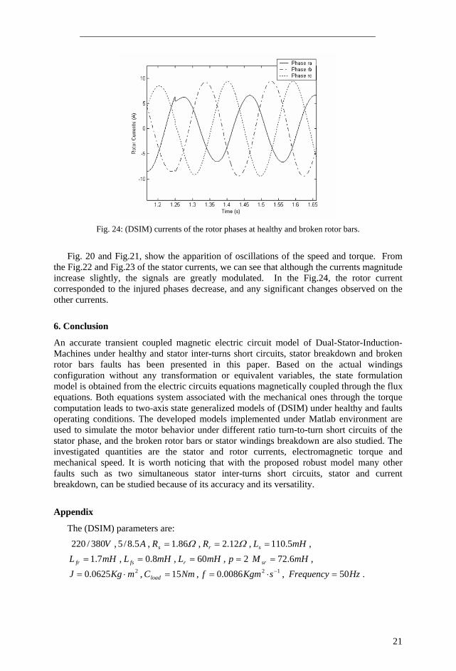
Fig. 24: (DSIM) currents of the rotor phases at healthy and broken rotor bars.
Fig. 20 and Fig.21, show the apparition of oscillations of the speed and torque. From
the Fig.22 and Fig.23 of the stator currents, we can see that although the currents magnitude increase slightly, the signals are greatly modulated. In the Fig.24, the rotor current corresponded to the injured phases decrease, and any significant changes observed on the other currents.
6. Conclusion
An accurate transient coupled magnetic electric circuit model of Dual-Stator-Induction-Machines under healthy and stator inter-turns short circuits, stator breakdown and broken rotor bars faults has been presented in this paper. Based on the actual windings configuration without any transformation or equivalent variables, the state formulation model is obtained from the electric circuits equations magnetically coupled through the flux equations. Both equations system associated with the mechanical ones through the torque computation leads to two-axis state generalized models of (DSIM) under healthy and faults operating conditions. The developed models implemented under Matlab environment are used to simulate the motor behavior under different ratio turn-to-turn short circuits of the stator phase, and the broken rotor bars or stator windings breakdown are also studied. The investigated quantities are the stator and rotor currents, electromagnetic torque and mechanical speed. It is worth noticing that with the proposed robust model many other faults such as two simultaneous stator inter-turns short circuits, stator and current breakdown, can be studied because of its accuracy and its versatility.
Appendix
The (DSIM) parameters are: V380/220 , A5.8/5 , Ω86.1=sR , Ω12.2=rR , mHLs 5.110= ,
mHL fr 7.1= , mHL fs 8.0= , mHLr 60= , 2=p mHM sr 6.72= , 20625.0 mKgJ ⋅= , NmCload 15= , 120086.0 −⋅= sKgmf , HzFrequency 50= .
22
References [1] G.K. Singh, "Multi-phase induction machine drive research – a survey", Elsevier, Electric
Power Systems Research, Vol. 61, pp. 139-147, 2002. [2] D. Hadiouche, H. Razik, A. Rezzoug, "Design of Novel Windings Configurations for VSI Fed
Dual-Stator Inductions Machines", Proceeding of the Electrimacs Conferences, August 18-21, 2002.
[3] S. Nandi, H. A. Toliyat, and X. Li, "Condition monitoring and fault diagnosis of electrical motors- E review", IEEE Transaction On Energy Conversion, vol. 20, No.4, pp. 719-730, December 2005.
[4] M.E.H. Benbouzid, "A review of induction motors signature analysis as a medium for fault detection", IEEE Transaction On Industrial Electronics, vol. 47, No.5, pp. 984-993, October 2000.
[5] H. Hammache, D. Moussaoui, K. Marouani and T. Hamdouche, "Magnetic properties in double star induction machines", Proceedings of the 2008 International Conference on Electrical Machines (ICEM ), Paper ID 1148, Portugal 2008.
[6] S. Hamdani, O. Touhami and R. Ibtiouen, "A generalized two axis model of s squirrel-cage induction motor for rotor fault diagnosis", Serbian journal of electrical engineering, vol. 5, No.1, pp. 155-170, May 2008.
[7] M. Rachek, Y. Méssaoudi and B. Oukacine, "Accurate Coupled magnetic Multi-turns Model of Induction Motors Under Turn-to-Turn stator short Circuits", International Conference On Electrical Engineering Design and Technologies (ICEEDT), Hammamet Tunisia, November 8-10, 2008.